


Abstract
Sandwich materials are increasingly used due to the possibility of improving their combined properties. However, some manufacturing operations become more complex, such as drilling, where it is more difficult to determine the optimal cutting conditions that provide the appropriate hole quality. In this context, the quality of the drilled holes of the carbon fiber plates with a foamed polyvinyl chloride core, a material used in marine environments at very low temperatures, among others, is analyzed. Due to the importance of surface quality in operations prior to the assembly of plates and the influence of delamination on the in-service behavior of materials, the objective is to determine the diameter deviation (∆D), circularity (CIR), and delamination (FD) at the entrance and exit of the hole after drilling plates of this material. This sandwich material has been drilled at low temperatures (−15, 0, and 15 °C) using compressed air as cooler. Different cutting conditions have been used regarding rotation speed and feed. An experimental and statistical study, including a response surface optimization for FD, and multiple response surface optimization for ∆D and CIR were used. Several ranges of suitable cutting conditions can be identified for each temperature.
1. Introduction
Carbon fiber reinforced composite materials continue to be studied due to their great versatility; an increasingly common use is their application in sandwich materials. The good behavior of carbon fiber at extremely low temperatures has led to the use of this material in satellites. The carbon fiber reinforced polymer (CFRP) and its sandwich materials have been increasing their use and expanding their applications [1]. As an innermost layer, a foam core is commonly used where lightweight materials are required, such as in wind turbine blades and in the marine and construction industries [2]. A material used as a core between two face-sheets is polyvinyl chloride (PVC). Considering that carbon fiber is a thermally stable material, while PVC can degrade at high temperatures [2] and, in cold climates, the degradation process of polymer matrices is weaker than in tropical or subtropical climates [3], a sandwich material composed of two CFRP sheets and a PVC core is suitable for use at low temperatures. These sandwich structures, due to their ability to absorb high energy, are used in infrastructure requiring protection against explosions; for example, ships, buildings, automobiles, and aircraft. Therefore, studies, such as material modeling [4,5,6], are being conducted to understand its behavior, especially in marine applications at very low temperatures [7,8]. Modeling and experimental studies encounter difficulties in generalizing the results, revealing the need to limit the results to specific environmental conditions and tools [9,10]. This can be extended to the results of manufacturing processes such as machining.
Drilling is a particularly complex process in sandwich materials because each material may require different cutting conditions and influence the quality of the holes. The size of the drilled holes, their circularity, and the delamination around the drilled surfaces are variables that can determine the feasibility of the operation or the need for additional operations. The deviation in the dimensions of the diameters, the circularity, also known as roundness, of the holes, and the delamination must be analyzed after a drilling operation to avoid poor adjustments in service. Vibrations of the drill bit during machining can cause diameter deviations, which could result in holes outside of tolerances. Due to the relevance of these variables to material behavior, they are commonly studied in plate or tube drilling, as well as delamination [11,12].
Delamination is one of the problems that can occur in structural composite materials by causing possible misalignments in riveted joints. According to Fard et al. [13], delamination analysis on the drill bit entry surface is important because this phenomenon can affect the structural integrity and surface quality, and it is important on the drill bit exit surface because it can affect the mechanical properties of the material.
Analyses of drilling CFRP [13,14,15,16] or sandwich materials with carbon fiber plates and foamed polyvinyl chloride [7] and aluminum honeycomb [17] cores using different cutting conditions and environmental temperatures can be found with disparate results. There does not seem to be unanimity regarding the influence of spindle speed and feed rate. The many applications of these materials necessitate the analysis of various combinations of materials, thicknesses, cutting conditions, and temperatures, among other factors. For this reason, it is not easy to find systematic patterns of behavior during drilling, and further testing and studies are still required.
Khan and Tan [18] find that at arctic temperatures (between −70 and −30 °C), this sandwich material (CFRP-PVC) sustains less impact damage than at room temperature. Also, with cryogenic cooling during CFRP drilling, adequate quality has been achieved [4,15], accomplishing strict tolerances. As can be observed, the behavior of this sandwich material under different situations is affected by temperature. However, it is not always necessary to lower the temperature to cryogenic environments, with compressed air cooling by vortex tube being an alternative. With this method, temperatures below 0 °C can be achieved.
With all the above considerations, and in view of possible maintenance operations in low-temperature areas and as a possible cooling method in manufacturing plants, compressed air using a vortex tube can be explored for its possibilities, shown in other materials. The aim is to evaluate the possibilities of overcoming the difficulties of drilling in materials of carbon fiber sandwich sheets with inner foam core, in particular with foamed polyvinyl chloride. This involves finding the appropriate cutting conditions by each layer that makes up the material to obtain the required quality within a specific temperature range. Due to the importance of surface quality in operations prior to the assembly of plates and the influence of the dimensions of the holes after drilling within tolerances and the delamination on service behavior of materials [17], the objective of this paper is to determine the diameter deviation taking tolerances into account, as well as the circularity and the delamination at the entrance and exit of the hole, after drilling plates of this material at temperatures close to 0 °C as yet another application of carbon fiber.
2. Materials and Methods
This section has been divided into two subsections. The first explains the materials, equipment, and procedures used experimentally. The second details the statistical procedures applied.
2.1. Experimental Methodology
CFRP sandwich sheets with an inner foam core were drilled. The carbon fibers presented a bidirectional 90°/0° orientation. Each CFRP sheet consisted of four layers with twill fabric and density of 1600 kg/m3. The binder used between the layers was epoxy resin. The core consisted of foamed polyvinyl chloride (PVC) with a density of 60 kg/m3. The thickness of the two CFRP sheets was 1 mm, and the core was 10 mm.
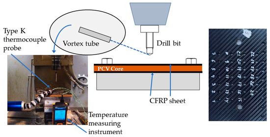
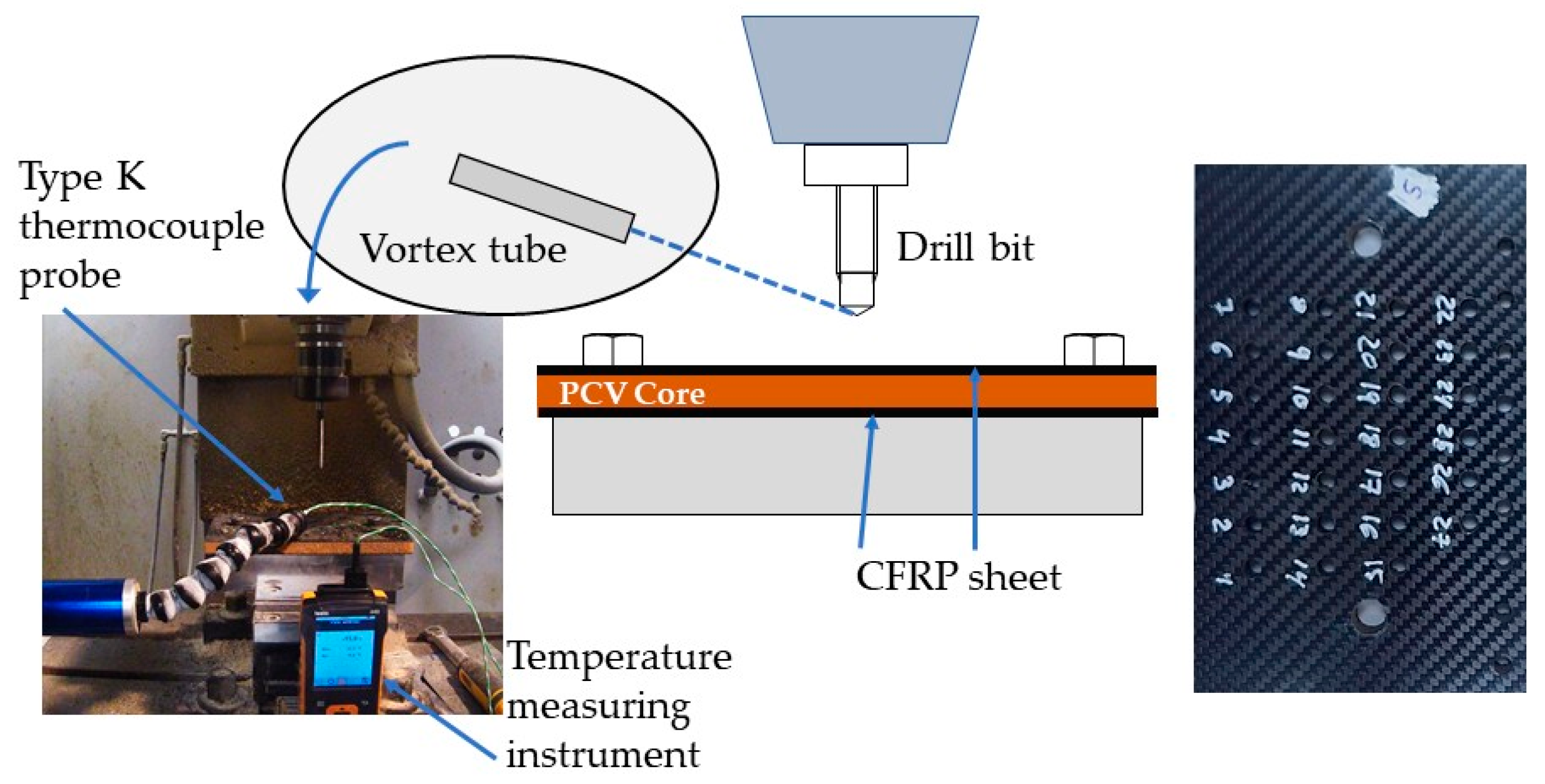
This sandwich material has been drilled in different environments at three temperatures, at room temperature, 15 °C, at 0 °C, and at −15 °C in a Manga Tongtai TMV-510 machining center (Tong-tai Machine & Tool Co., Ltd., Kaohsiung Hsien, Taiwan), using compressed air as a cooler to lower the temperature. Cooling was achieved by a Ranque–Hilsch vortex tube Vortec 610 (Vortec, Cincinnati, OH, USA) with a cold fluid outlet. The tests were carried out on three different days to avoid any potential impact from temperature changes [19]. This method has yielded good results in the machining of materials such as reinforced polyether-ether-ketone [20] or metals [21,22]. The temperature was measured by a Testo 440 instrument using a Type K thermocouple probe (Testo SE & Co. KGaA, Titisee-Neustadt, Germany), maintaining continuous monitoring (see Figure 1). The air directly impacted the tool at a pressure of 0.8 MPa and at approximately 30 mm, and temperatures were kept constant throughout each test, within a range of ±0.2 °C. To reach the target temperatures of 0 and −15 °C, the airflow was directed onto the drill bit tip for 9 and 12 min, respectively. The plates were cooled for the same number of minutes as the drill bit to assess the influence of environments at different temperatures.
Figure 1.
Assembly at the machining center and one of the drilled plates.
A 6.3 mm diameter Garant drill bit with two flutes was used (Hoffmann Iberia Quality Tools S.L, Madrid, Spain); this drill bit was designed for use in fiber reinforced polymers, using as material tungsten carbide WC with a polycrystalline diamond (PCD) coating; this coating is recognized as a good option to achieve adequate quality in the performed holes [23] in CFRP. Its geometric main characteristics are: 90° point angle, 35° helix angle, 2 mm web thickness, 0.22 mm margin, and 0.16 mm body clearance. Different cutting conditions have been used regarding rotation speed and feed rate (see Table 1). The cutting conditions were set based on previous tests aimed for high performance (high feed rate) to increase production speed, as well as studies from the literature. The rotation speed is also high compared to that used in other studies [1,15] and is comparable to that used for this same sandwich material drilled at other temperatures [7] to determine the results in extreme situations. The tests were repeated three times, performing a total of 81 tests using nine drill bits, three for each temperature, to avoid tool wear.
Table 1.
Environmental and cutting conditions.
The variables to be studied to define the diameter deviation, circularity, and delamination factor were measured at the drill bit entry point on the top surface of the plates and at the drill bit exit point on the bottom surface of the plates. They were: inlet diameter (Di), outlet diameter (Do), inlet and outlet radius (Ri and Ro), inlet delamination diameter (Ddi), and outlet delamination diameter (Ddo). The delamination diameter is always the maximum damaged diameter.
To measure circularity maximum delamination diameter under an optical magnification 20×, a three-dimensional measurement device with a TESA VISIO optical sensor (TESA SA, Renens, Switzerland) was used. Alicona Infinity Focus (Bruker Alicona GmbH, Graz, Austria) was used as an optical measurement instrument to measure the deviation diameter. Note that contact measurements have been avoided because touching a loose fiber could lead to errors in the measurement reading. Diameters and radii were measured according to ISO 4291 [24]. Of the four proposed methods (Minimum Zone Circle, Least Squares Circles, Maximum Inscribed Circle, and Minimum Circumscribed Circle), the Least Squares Circles method has been selected because it is robust [25] and widely used in manufacturing environments [26]. The diameter deviation (∆D) was determined by subtracting the actual drill bit diameter from the least square circle measured for each hole. The circularity (CIR) was determined by calculating the radius of the minimum circumscribed circle and the radius of the maximum inscribed circle, measured from the center of the least square circle. The values of each point were found by measuring the values of radii and diameters every 15° along the hole, which is acceptable in manufacturing environments [15,20].
The delamination is assessed through the delamination factor (FD) as the ratio of maximum delamination diameter (Dd) to drill nominal diameter (Dnom), using Equation (1):
FD = Dd/Dnom,
Note that the Dd measurement assumes that a single damage, even if isolated, would generate a high FD.
2.2. Statistical Methodology
From a statistical perspective, an experimental design was performed, specifically a 3-level factorial, 33, resulting in a total of 27 experiments. The factors and levels can be observed in Table 1; the factors were temperature, feed rate, and rotational velocity, while the levels were the three values defined for each of them (see Table 1); finally, the responses were the variables analyzed (∆Di, ∆Do, CIRi, CIRo, FDi, and FDo). After, a second-order model was defined for the factors N, F, and T; this model allows a good fit to find a relationship between the variables, factors, and parameters analyzed. ANOVA studies and optimization of results were also performed; in the ANOVA results and for each variable, factors and interactions with a p-value less than 0.05 were considered significant at a confidence interval of 95%, as is usually in the literature [27].
Finally, an optimization process was carried out. The strategy was defined as follows: maintain the diameter deviation (∆Di and ∆Do) and circularity (CIRi and CIRo) at zero and maintain the delamination (FDi and FDo) factor at 1.
Moreover, a study based on Multiple Response Surface Optimization was carried out to try to find the optimal cutting conditions at the entrance and exit of the drilled holes. For this purpose, the desirability function, di, ref. [28] was calculated, according to Equations (2) and (3):
where di(ŷi) is a function that takes values between 0 and 1, ŷi is ith estimated response of the variable (∆Di, ∆Do, CIRi, CIRo, FDi, and FD), TAi is the target, Li is the lower acceptable value, Ui is the upper acceptable value, s and t are the weight, ri is the impact value, and, finally, D is the global desirability. The values of TAi, Li, and Ui were taken from experimental data, while the values of s, t, and ri could be defined by the user.
The steps followed from the design of experiments to a multiple optimization are detailed in Montgomery et al. [29]. All calculations were performed using Statgraphics Plus 5.0 software (Statpoint Technologies, Inc., Warrenton, VA, USA) [30].
3. Results
3.1. Experimental Results
Detailed outcomes can be seen in Table 2; these are the result of the average of the three values measured for each variable. The phenomenon of diameter contraction after drilling can be observed in holes from tests 1, 2, 19, and 20 at the entrance of the drill bit and in holes from tests 1, 5, 11, 15, 23, and 24 at the exit of the drill bit. This contraction occurs at all temperatures (15 °C, 0 °C, and −15 °C) because it is independent of the environment. This phenomenon was explained by Weinert et al. [31] when identifying a relaxation of the laminate in carbon fiber/epoxy plates during drilling. Firstly, it is observed for all variables that considering the measurements at the entrance and exit of the hole makes it difficult to find optimal conditions.
Table 2.
Outcomes under different environmental and cutting conditions.
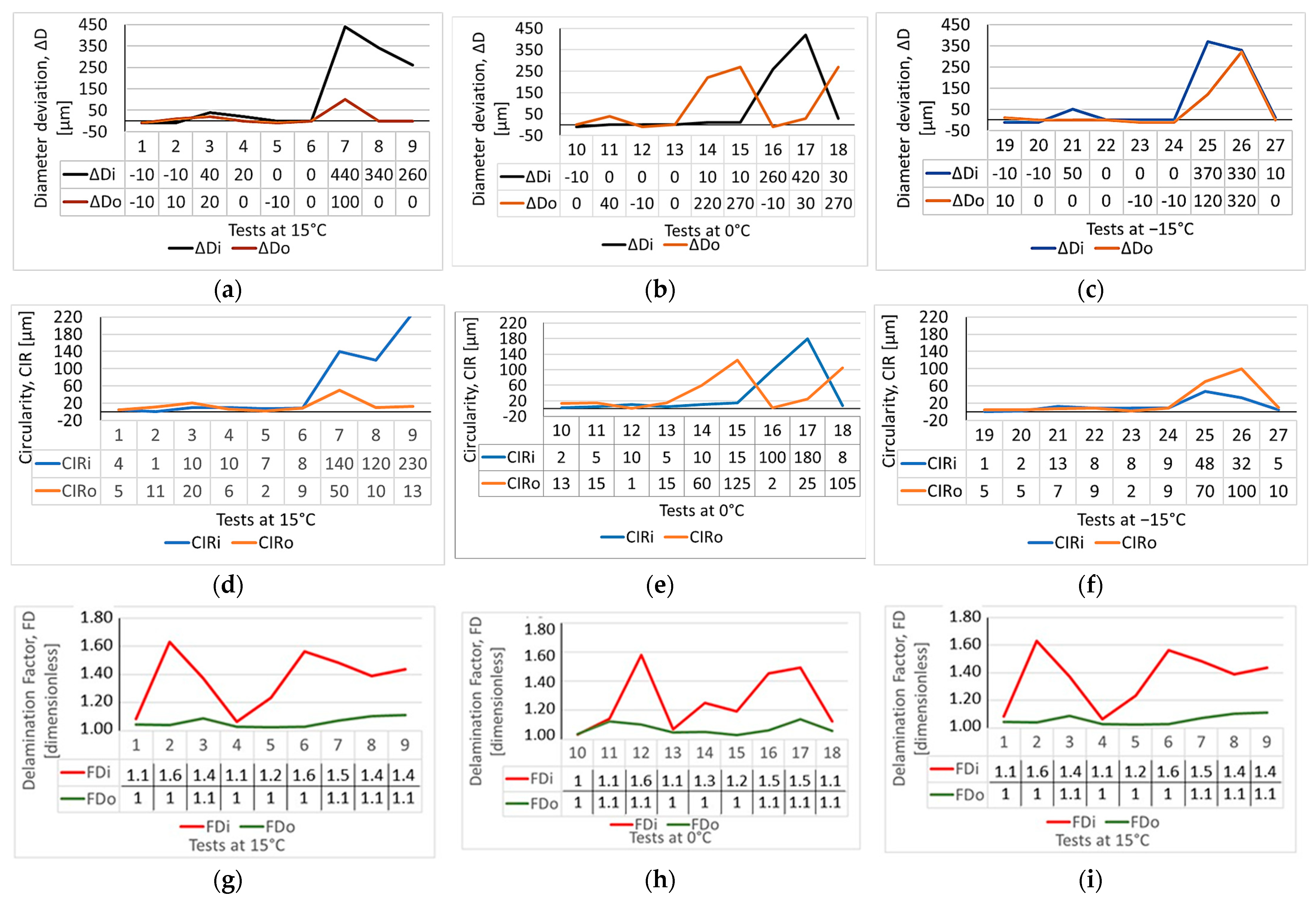
The results show very different data considering the cutting conditions and the environmental conditions. Figure 2 shows the ∆D, CIR, and FD values considering the different temperatures. In the diameter deviations, it is observed that the holes have very different tolerances, from H1 (tolerance of 1 µm) to H15 (tolerance of 0.58 mm), according to the ISO 286-2 standard designation [32] and excluding undersized holes. According to the data in Table 2 and Figure 2a–c, and including only the inlet and outlet oversizing holes, holes meeting tolerances of less than 0.36 mm, H9, can be found (holes form tests 8, 10, 16, 22, 26, and 31). These tolerances are typical of the aerospace sector and are considered strict [33]. This indicates the difficulty of systematizing the results.
Figure 2.
Diameter deviation, circularity and delamination factor at inlet and outlet of drill bit: (a) ∆D at 15 °C; (b) ∆D at 0 °C; (c) ∆D at −15 °C; (d) CIR at 15 °C; (e) CIR at 0 °C; (f) CIR at −15 °C; (g) FD at 15 °C; (h) FD at 0 °C; (i) FD at −15 °C.
Regarding circularity, differences are also observed between the CIRi and CIRo values in Table 2 and Figure 2d–f. The minimum value found is 1 µm for both cases. CIR reaches low values for both low and very high cutting conditions, which can indicate that the relationship between F and N can influence it. For high N values, lower circularity values are observed at −15 °C.
The delamination factor shows large differences between the values at the inlet and outlet of the drill bits can also be seen in Table 2 and Figure 2g–i. A similar phenomenon has been observed in CFRP plates [15]. This phenomenon is alike at all temperatures probably because the heating produced during drilling balances the environmental conditions, even though the heating is much lower than in alloys; however, at room temperatures, FD at the entrance and exit is similar to that found in other studies [34]. At the entrance of the drill bit, Fard et al. [13] have found values in plates of CFRP of 7 mm thickness between 1.015 and 1.30. Note that these values require careful analysis because, as mentioned above, delamination at the drill bit entry can affect the structural integrity and surface quality.
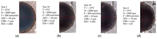
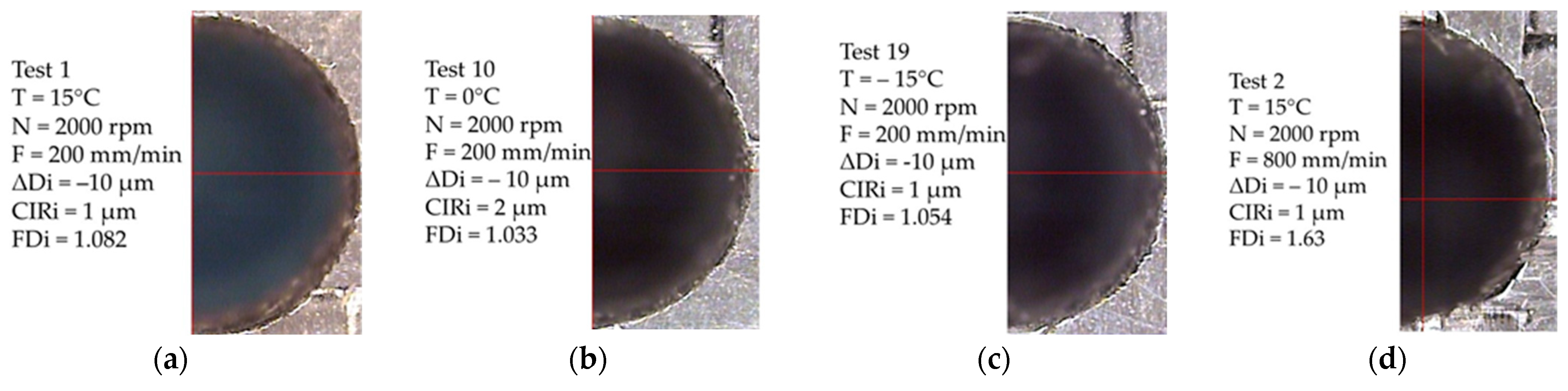
FD at the drill bit exit has lower values than at the entrance; these values range from 1.02 to 1.13, and they are lower than others found in the literature in CFRP drilling [15]. Details of the delamination can be observed in Figure 3. Figure 3a–c show, at the hole entrance, the delamination achieved with low cutting conditions and at each of the temperatures. These holes have similar values in the variables, and no delamination defects are observed; hole 10 is the one with the least delamination at the entrance (Figure 3b). In Figure 3d, the hole with maximum delamination at the drill bit entry is observed, as well as a slight peeling, probably due to an increase in temperature because under the same cutting conditions and at lower temperatures, FD is lower (see Figure 2g–i).
Figure 3.
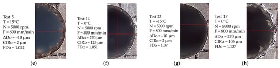
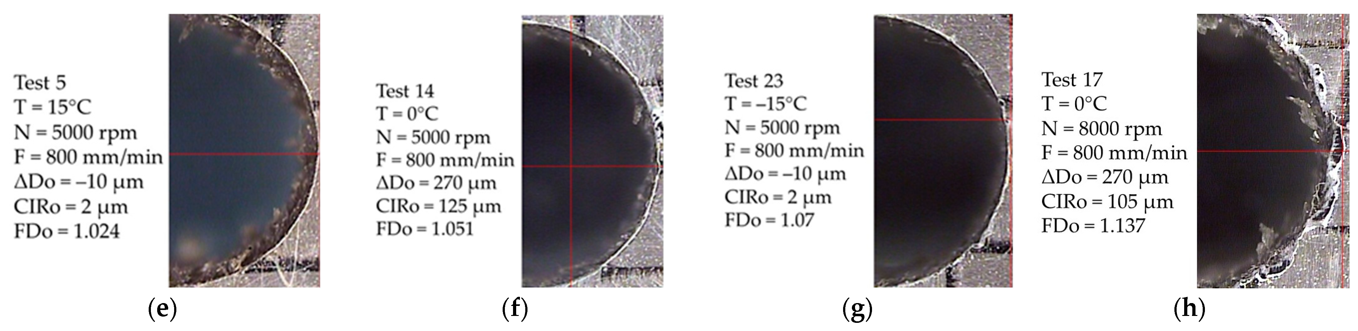
Effects of delamination: (a) Inlet delamination diameter at 15°C, 2000 rpm, and 200 mm/min, hole 1; (b) Inlet delamination diameter at 0°C, 2000 rpm, and 200 mm/min, hole 10; (c) Inlet delamination diameter at −15°C, 2000 rpm, and 200 mm/min, hole 19; (d) Inlet delamination diameter at 15°C, 2000 rpm, and 800 mm/min, hole 2; (e) Outlet delamination diameter at 15°C, 5000 rpm, and 800 mm/min, hole 5; (f) Outlet delamination diameter at 0°C, 5000 rpm, and 800 mm/min, hole 14; (g) Outlet delamination diameter at −15°C, 5000 rpm, and 800 mm/min, hole 23; (h) Outlet delamination diameter at 0°C, 8000 rpm, and 800 mm/min, hole 17.
Similarly, Figure 3e–g show delamination at the drill bit exit, at different temperatures and under the same cutting conditions. Furthermore, the hole shown in Figure 3e has the least delamination found, and the hole shown in Figure 3h has the most delamination found. In the latter, damage caused by spalling is observed, which has also resulted in high circularity and a high deviation in diameter.
3.2. Statistical Analysis
3.2.1. Analysis of Variance
This analysis of variance can be seen in Table 3. From an ANOVA result, p-values equal to 1 are obtained in ∆Do (for N2), FDi (for T, F × T and N × T) and FDo (for T, F × T and N × T). These elements have no influence on the outcomes.
Table 3.
Analysis of variance for ∆Di, and ∆Do, CIRi, CIRo, FDi, and FDo.
N, F × N, and N2 have been found to be significant factors for ∆Di, at 95%, with a total contribution of 78.85%. The influence of N on the results of the diameter deviation at the entrance is clear. In ∆Do, there are no factors significant at 95%, although as can be seen in Table 3, if the confidence interval is widened, N and F2 are significant at 90%.
Regarding CIRi, N, T, N2, and N × T are observed as significant factors, which represents a contribution of 71.92%; whereas in CIRo, only N is significant.
With respect to FD (FDi and FDo), temperature is not a significant factor, either as a main factor or in its interactions. For FDi, F, F × N, and N2 are significant with a total contribution of 73.70%. In the case of FDo, the results are very different since only F2 is significant with a contribution of 15.82%.
3.2.2. Optimization
The optimization process carried out has shown very different results in the variables, as can be seen in Table 4. For ∆Di and ∆Do, the optimum is reached with similar cutting conditions, with N close to 5000 rpm and F close to 1400 mm/min, although the temperature differs.
Table 4.
Optimal conditions.
CIRi reaches its optimal value (CIRi = 0) under low cutting conditions (see Table 4). Conversely, an optimal CIRo (CIRo = 0) is found at a temperature of 15 °C and high cutting conditions.
Although mathematical optimization has found the best value at a temperature of 0 °C (FDi = 1 and FDo = 1.04), as seen in the ANOVA study, temperature is not a significant factor for delamination.
3.2.3. Multiple Response Surface Optimization
To find the cutting and environmental conditions that can optimize the values of each variable at the inlet and outlet of the hole, a multiple response surface optimization has been performed for ∆D and CIR. FD has been excluded because it has not been possible to optimize the input and output values simultaneously. Table 5 shows the limit values of the variables, the values of the weights, and the impact taken. As TA is the target, its value is zero for all variables (∆Di, ∆Do, CIRi, and CIRo). Regarding Li and Ui, they represent the minimum and the maximum experimental values obtained (see Table 2). Li takes values from tests 1, 2, 10, 19, and 20 for ΔDi (value −10 μm), from tests 1, 5, 11, 15, 23, and 24 for ΔDo (value −10 μm), from tests 2 and 19 for CIRi (value 1 μm), and from test 11 for CIRo (value 1 μm). Ui takes values from test 7 for ΔDi (value 440 μm), from test 26 for ΔDo (value 320 μm), from test 9 for CIRi (value 230 μm), and from test 14 for CIRo (value 125 μm). Finally, s, t, and r are values given by user and constrained by the software; in this case, Statgraphics allows values between 1 and 10 for s and t, and between 1 and 5 for r. It should be noted that variations in these latter values do not alter the results obtained.
Table 5.
Values considered in the desirability function.
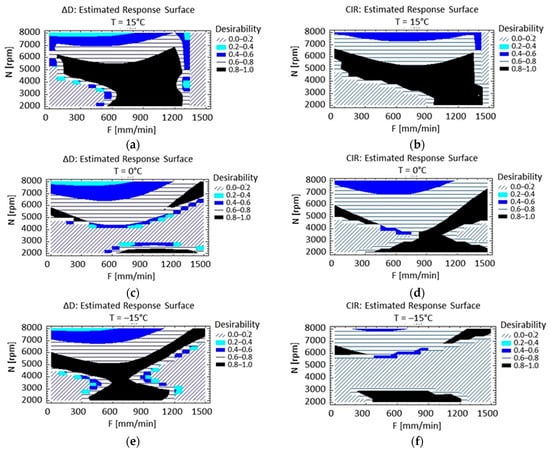
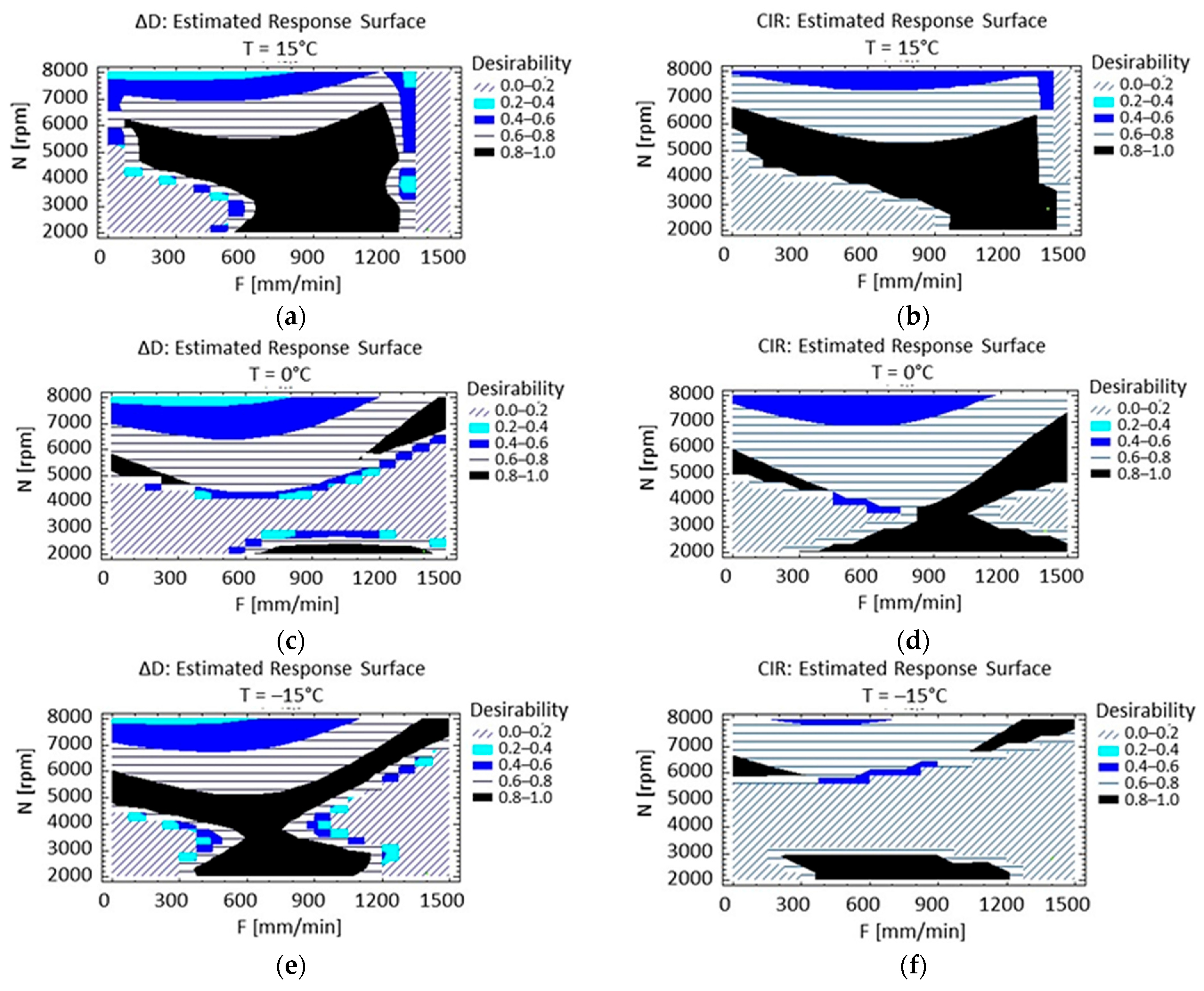
Figure 4 shows the optimal values for ∆D and CIR, which are those that achieve a desirability close to 1. Despite the very different results found according to the cutting conditions, high desirability values have been found: 0.99 for ∆D and 0.97 for CIR. Applying Equation (3), an overall desirability, D, of 0.98 is obtained. Figure 4 shows the results for all temperatures, revealing common areas across all of them, despite the different results.
Figure 4.
Contours of estimated response surface for diameter deviation (∆Di and ∆Do) and circularity (CIRi and CIRo): (a) ∆D at 15 °C; (b) CIR at 15 °C; (c) ∆D at 0 °C; (d) CIR at 0 °C; (e) ∆D at −15 °C; (f) CIR at −15 °C.
Figure 4a,b show the suitable cutting conditions at a temperature of 15 °C, revealing common areas across a wide range, where a combination of different N and F leads to obtaining acceptable deviations in diameters and circularity, although in general high values of N and especially F should be excluded. This is even more pronounced at 0 °C (Figure 4c,d) and −15 °C (Figure 4e,f); they clearly show the influence of the interactions between F and N by identifying opposing areas as acceptable. In the diameter deviation, the maximum desirability, 0.97, was found for N = 2813 rpm, F = 1400 mm/min, and T = 15 °C, with values of ∆Di = 9.1 µm and ∆Do = 1 µm. In the case of circularity, the maximum desirability, 0.99, was found for N = 2110 rpm, F = 1400 mm/min, and T = −6 °C, with values of CIRi = 7.7 µm and CIRo = 4.8 µm. Comparing it with the values obtained in the individual optimization (see Table 4), the diameter deviation requires a similar F (1400 mm/min) but a lower N, although for high values of N and F it can also be optimized (see Figure 4a,c,e) at lower temperatures. This may mean that mitigating the heat generated by the rotational speed during drilling is beneficial for hole quality. Concerning circularity, the differences are greater between individual optimization (see Table 4) and common optimization (see Figure 4b,d,f). The results obtained for FD should also be taken into account; although its optimum for FDi and FDo has been reached at 0 °C, the temperature is not significant (see Table 3). Therefore, several ranges of suitable cutting conditions can be identified for each temperature.
3.3. Validation of Results
To validate the conditions given in the optimization, additional tests have been carried out, prepared in the same way as explained in the Section 2.1. Table 6 displays the comparison between the optimal and experimental results; it includes the previously found optimal values for FD. The previously found optimal values for FD have been included in this calculation. The results, although with some deviation, can validate the optimization.
Table 6.
Comparison of results.
4. Discussion
The results in the holes at the entry and exit of the drill bit of the variables studied are very different. This is corroborated by the significant factors found for each variable, and this occurs at room temperature and at lower temperatures obtained by cooling using the Ranque–Hilsch vortex tube, as well as in sandwich materials and in CFRP materials only.
In the case of the difference in diameters, deviations are influenced by diameter contraction. Shrinkage has been identified in cryogenic drilling of CFRP [31]; in the sandwich material studied in this article with two different thicknesses in the core [7], the possible contraction appears in the prediction of deviations based on experimental data. On the other hand, differences between the ∆Di and ∆Do values were also identified in CFRP plates in other studies [33].
Regarding the CIR variable, the significant N × T interaction can explain the experimental results, where at temperatures of −15 °C, CIR is lower for high N.
As mentioned in Section 3, FD shows large differences between the values at the inlet and outlet of the drill bits, as can also be seen in CFRP [13] at all temperatures. In the drill bit outlet area, FD has lower values than in the inlet area, so the core of the plates does not hinder chip removal while the feed rate (significant factor) decisively influences the entry area; besides, they are lower than others found in other studies in CFRP drilling at room temperature [15].
The delamination factor and the diameter deviations at the inlet are lower at room temperature than at cryogenic temperatures in CFRP plates [16].
As with ∆D and CIR, the very different significant factors for FD are evidenced by the behavior of the material, although multiple response surface methodology has allowed for clarifying the appropriate conditions. Compressed air cooling using a Ranque–Hilsch vortex tube is a viable and very low-cost option.
5. Conclusions
The following conclusions can be drawn from the study carried out on drilling in Carbon Fiber Plates with Foamed Polyvinyl Chloride Core at low temperatures:
- The feasibility of drilling Carbon Fiber Plates with Foamed Polyvinyl Chloride Core at low temperatures has been demonstrated.
- A diameter contraction after drilling occurs at all temperatures (15 °C, 0 °C, and −15 °C) because it is independent of the environment because relaxation of the laminate in carbon fiber/epoxy plates occurs during drilling.
- Large differences were found between the values of the variables (∆D, CIR, and CIR) at the inlet and outlet of the holes. The different significant factors identified in the ANOVA study corroborate this.
- N is a significant factor for the variables ∆Di, CIRi, and CIRo, while F is significant for FDi. Temperature is only significant for CIRi and therefore does not influence FD. All this indicates the difficulty of unifying cutting conditions to optimize hole quality; for this reason, it remains a topic of research.
- The difficult simultaneous optimization for ∆D, CIR, and FD can be found around N close to 2000 rpm and 1300 mm/min and 7000 rpm and an F close to 600–700 mm/min, at any low temperature.
As for future developments, given the potential of this material, further tests of different machining processes are planned, including using vortex tube cooling to take advantage of an effective and low-cost method. Environmental and cutting conditions could be analyzed to determine their influence on variables such as tool life and thus be able to establish a new theoretical model.
Author Contributions
Conceptualization, R.D. and M.M.M.; methodology, R.D., N.R.-P., A.G.-D. and M.M.M.; validation, N.R.-P. and A.G.-D.; formal analysis, R.D., A.G.-D. and M.M.M.; investigation, R.D. and N.R.-P.; resources, R.D., A.G.-D. and M.M.M.; data curation, N.R.-P. and A.G.-D.; writing—original draft preparation, R.D., N.R.-P., A.G.-D. and M.M.M.; writing—review and editing, R.D., N.R.-P., A.G.-D. and M.M.M.; supervision, R.D. and M.M.M.; funding acquisition, R.D. and M.M.M. All authors have read and agreed to the published version of the manuscript.
Funding
This research was funded by the Spanish Ministry of Science and Innovation, projects RTI2018-102215-B-I00 and PID2022-143329OA-I00.
Institutional Review Board Statement
Not applicable.
Informed Consent Statement
Not applicable.
Data Availability Statement
The original contributions presented in this study are included in the article. Further inquiries can be directed to the corresponding author.
Acknowledgments
Research Group on Industrial Production and Manufacturing Engineering (IPME) of UNED.
Conflicts of Interest
The authors declare no conflicts of interest.
References
- Zhu, Z.; Sun, X.; Guo, K.; Sun, J.; Li, J. Recent Advances in Drilling Tool Temperature: A State-of-the-Art Review. Chin. J. Mech. Eng. 2022, 35, 148. [Google Scholar] [CrossRef] [Scilit]
- Jang, W.C.; Roh, H.D. Sandwich Composites Manufacturing: A Review of Materials, Methods, Applications and Challenges. Int. J. Precis. Eng. Manuf. 2025, 26, 2093–2109. [Google Scholar] [CrossRef] [Scilit]
- Lebedev, M.P.; Startsev, O.V.; Kychkin, A.K.; Polyakov, V.V. Effects of cold climates on polymer composite material properties. Procedia Struct. Integr. 2020, 30, 76–81. [Google Scholar] [CrossRef] [Scilit]
- Feng, D.; Aymerich, F. Damage prediction in composite sandwich panels subjected to low-velocity impact. Compos. Part A-Appl. Sci. Manuf. 2013, 52, 12–22. [Google Scholar] [CrossRef] [Scilit]
- Alanbay, B.; Batra, R.C. Optimization of Blast Mitigating Sandwich Structures with Fiber-Reinforced Face Sheets and PVC Foam Layers as Core. Thin-Walled Struct. 2022, 179, 109721. [Google Scholar] [CrossRef] [Scilit]
- Wanchoo, P.; Shyamal, K.; Pandey, A.; Shukla, A. Advances in naval composite and sandwich structures for blast and implosion mitigations. J. Sandw. Struct. Mater. 2024, 26, 152–174. [Google Scholar] [CrossRef] [Scilit]
- Domingo, R.; Marín, M.M.; Rodríguez-Padial, N.; Álvarez-Fernández, R. Preassembly Cryogenic Drilling in Carbon Fiber Sandwich Sheets with Inner Foam Core. Appl. Sci. 2025, 15, 2719. [Google Scholar] [CrossRef] [Scilit]
- Bull, P.H.; Edgren, F. Compressive strength after impact of CFRP-foam core sandwich panels in marine applications. Compos. B Eng. 2004, 35, 535–541. [Google Scholar] [CrossRef] [Scilit]
- Osa-uwagboe, N.; Silberschimdt, V.V.; Aremi, A.; Demirci, E. Mechanical behaviour of fabric-reinforced plastic sandwich structures: A state of-the-art review. J. Sandw. Struct. Mater. 2023, 25, 591–622. [Google Scholar] [CrossRef] [Scilit]
- Sadiq, M.A.; Kovács, G. Optimization of Composite Sandwich Structures: A Review. Machines 2025, 13, 536. [Google Scholar] [CrossRef] [Scilit]
- Slamani, M.; Elhadi, A.; Amroune, S.; Arslane, M.; Jomaa, W.; Fouad, H.; Chatelain, J.F.; Jawaid, M. Investigating the impact of drill material on hole quality in jute/palm fiber reinforced hybrid composite drilling with uncertainty analysis. Heliyon 2024, 10, e36925. [Google Scholar] [CrossRef] [Scilit] [PubMed]
- Seif, A.; Sadoun, A.M.; Fathy, A.; Megahed, A.A. Evaluation of hole quality in drilling process of GF/Aluminum wire mesh reinforced epoxy composites. Alex. Eng. J. 2024, 94, 257–273. [Google Scholar] [CrossRef] [Scilit]
- Fard, M.G.; Baseri, H.; Azami, A.; Zolfaghari, A. Prediction of Delamination Defects in Drilling of Carbon Fiber Reinforced Polymers Using a Regression-Based Approach. Machines 2024, 12, 783. [Google Scholar] [CrossRef] [Scilit]
- Ameur, M.F.; Habak, M.; Kenane, M.; Aouici, H.; Cheikh, M. Machinability analysis of dry drilling of carbon/epoxy composites: Cases of exit delamination and cylindricity error. Int. J. Adv. Manuf. Technol. 2017, 88, 2557–2571. [Google Scholar] [CrossRef] [Scilit]
- Khanna, N.; Pusavec, F.; Agrawal, C.; Krolczyk, G.M. Measurement and evaluation of hole attributes for drilling CFRP composites using an indigenously developed cryogenic machining facility. Measurement 2020, 154, 107504. [Google Scholar] [CrossRef] [Scilit]
- Xia, T.; Kaynak, Y.; Arvin, C.; Jawahir, I.S. Cryogenic cooling-induced process performance and surface integrity in drilling CFRP composite material. Int. J. Adv. Manuf. Technol. 2016, 82, 605–616. [Google Scholar] [CrossRef] [Scilit]
- Ekici, E.; Uzun, G.; Altas, S. Evaluation of the effects of drilling parameters, tool geometry and core material thickness on thrust force and delamination in the drilling of sandwich composites. Surf. Rev. Lett. 2021, 28, 2150112. [Google Scholar] [CrossRef] [Scilit]
- Khan, M.H.; Tan, K.T. Post-impact flexural collapse modes of composite sandwich structures in Arctic conditions: Analytical prediction and experimental validation. Compos. Sci. Technol. 2020, 195, 108187. [Google Scholar] [CrossRef] [Scilit]
- Kichhannagari, S. Effects of Extreme Low Temperature on Composite Materials. Master’s Thesis, University of New Orleans, New Orleans, LA, USA, 2024. [Google Scholar]
- Domingo, R.; de Agustina, B.; Marín, M.M. Study of Drilling Process by Cooling Compressed Air in Reinforced Polyether-Ether-Ketone. Materials 2020, 13, 1965. [Google Scholar] [CrossRef] [Scilit]
- Singh, G.R.; Sharma, V.S. Analyzing machining parameters for commercially puretitanium (Grade 2), cooled using minimum quantity lubrication assisted by a Ranque-Hilsch vortex tube. Int. J. Adv. Manuf. Technol. 2017, 88, 2921–2928. [Google Scholar] [CrossRef] [Scilit]
- Mia, M.; Singh, G.R.; Gupta, K.M.; Sharma, V.S. Influence of Ranque-Hilsch vortex tube and nitrogen gas assisted MQL in precision turning of Al 6061-T6. Precis. Eng. 2018, 53, 289–299. [Google Scholar] [CrossRef] [Scilit]
- Binali, R.; Ribeiro da Silva, L.R.; Pimenov, D.Y.; Kuntoglu, M.; Machado, A.R.; Linul, E. A review on progress trends of machining of Carbon Fiber Reinforced Plastics. J. Mater. Res. Technol. 2024, 33, 4332–4359. [Google Scholar] [CrossRef] [Scilit]
- ISO 4291; Methods for the Assessment of Departure from Roundness. Measurement of Variations in Radius. International Organization for Standardization: Geneva, Switzerland, 1985.
- Sui, W.; Zhang, D. Four Methods for Roundness Evaluation. Phys. Procedia 2012, 24, 2159–2164. [Google Scholar] [CrossRef] [Scilit]
- Kotlapati, A.; Hiremath, S.S. Innovative Approach for Machining Twin Holes on Superalloy-Nimonic 263 Using μ-EDM. J. Mater. Eng. Perform. 2025, 34, 13881–13897. [Google Scholar] [CrossRef] [Scilit]
- Montgomery, D.C.; Runger, G.C. Applied Statistics and Probability for Engineers, 7th ed.; John Wiley & Sons, Inc.: Hoboken, NJ, USA, 2018. [Google Scholar]
- Derringer, G.; Suich, R. Simultaneous optimization of several response variables. J. Qual. Technol. 1980, 12, 214–219. [Google Scholar] [CrossRef] [Scilit]
- Montgomery, D.C.; Keats, J.B.; Perry, L.A.; Thompson, J.R.; Messina, W.S. Using statistically designed experiments for process development and improvement: An application in electronics manufacturing. Robot. Comput. Manuf. 2020, 16, 55–63. [Google Scholar] [CrossRef] [Scilit]
- Statgraphics. Available online: http://statgraphics.net (accessed on 30 June 2025).
- Weinert, K.; Brinkel, F.; Kempmann, C.; Pantke, K. The dependency of material properties and process conditions on the cutting temperatures when drilling polymers. Prod. Eng. 2007, 1, 381–387. [Google Scholar] [CrossRef] [Scilit]
- ISO 286-2; Geometrical Product Specifications (GPS)—ISO Code System for Tolerances on Linear Sizes—Part 2: Tables of Standard Tolerance Classes and Limit Deviations for Holes and Shafts. International Organization for Standardization (ISO): Geneve, Switzerland, 2010.
- Koklu, U.; Morkavuk, S.; Featherston, C.; Haddad, M.; Sanders, D.; Aamir, M.; Pimenov, D.Y.; Giasin, K. The effect of cryogenic machining of S2 glass fibre composite on the hole form and dimensional tolerances. Int. J. Adv. Manuf. Technol. 2021, 115, 125–140. [Google Scholar] [CrossRef] [Scilit]
- Domingo, R.; García, M.; Sánchez, A.; Gómez, R. A sustainable evaluation of drilling parameters for PEEK-GF30. Materials 2013, 6, 5907–5922. [Google Scholar] [CrossRef] [Scilit]

Disclaimer/Publisher’s Note: The statements, opinions and data contained in all publications are solely those of the individual author(s) and contributor(s) and not of MDPI and/or the editor(s). MDPI and/or the editor(s) disclaim responsibility for any injury to people or property resulting from any ideas, methods, instructions or products referred to in the content. |
© 2026 by the authors. Licensee MDPI, Basel, Switzerland. This article is an open access article distributed under the terms and conditions of the Creative Commons Attribution (CC BY) license.