


Abstract
This study investigates the quasi-static and fatigue strength of copper-brazed 316L stainless steel. Quasi-static and fatigue tests were conducted at room temperature (20 °C) using a Zwick/Roell Vibrophore 100 testing machine and specially designed copper-brazed specimens. Two types of specimens were prepared—tensile and shear specimens—to obtain the stress–strain relationships (σ–ε and τ–ε) and the fatigue life (S–N) curves. Based on the experimental results, the quasi-static and fatigue strengths of the copper-brazed joints under external tensile and shear loading were evaluated. The fatigue tests reveal that the shear fatigue strength is significantly lower than the tensile fatigue strength. Furthermore, a comprehensive investigation was conducted, focusing on the metallographic characterisation of the brazed joint and fractographic analyses of fracture surfaces obtained under quasi-static and fatigue loading, with particular emphasis on the shear strength of the investigated brazed joint. The experimental results obtained may be crucial for designing engineering structures (e.g., plate heat exchangers), where copper-brazed joints are the weakest members of the structure.
1. Introduction
Copper-brazed steel joints refer to constructional components or machine parts made from steel that have been joined using copper-based brazing filler metal [1,2,3]. The brazing process involves heating the base metal (i.e., steel) to a temperature below its melting point, allowing the molten copper filler to flow into the joint through capillary action [4,5]. Copper-brazed steel joints are widely used in different industrial applications due to their key advantages, including high shear strength, good thermal and electrical conductivity, corrosion resistance, and minimal distortion. Typical applications of copper-brazed steel joints are in the Automotive industry (oil coolers, fuel and hydraulic lines, transmission components with high wear resistance, etc. [6,7]), Aerospace and Defence industry (hydraulic system tubing [8,9]), Energy and Power systems (electrical switchgear and busbar connections, fuel gas distribution components, transformer cooling tubes, etc. [10,11]) and Manufacturing industry (cutting tools, brazed wear plates or liners, etc. [12]).
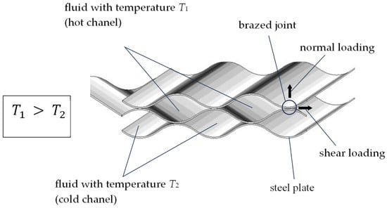
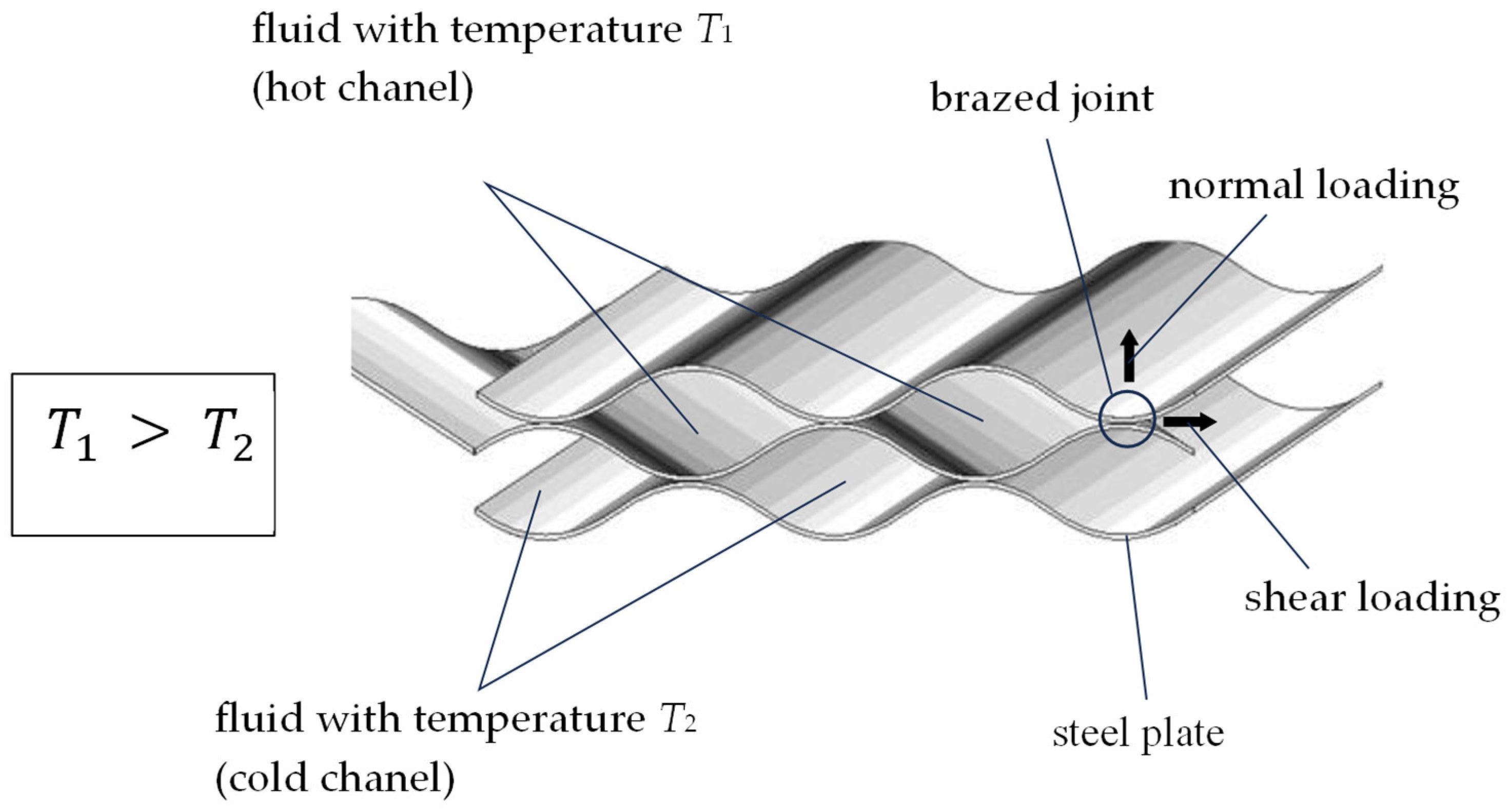
Copper is also widely adopted as a filler material for brazing stainless steel due to its favourable wetting behaviour [13,14] and capillary effect [15,16]. Typical applications of copper-brazed stainless steel are Plate Heat Exchangers (PHEs), which transfer heat between fluids at different temperatures without mixing them [17,18,19]. Such a PHE construction consists of multiple parallel plates that separate the hot and cold flow channels (see Figure 1). The number of plates and their thickness are primarily determined by the required thermal performance and operating conditions. From a structural integrity perspective, the internal fluid pressure induces membrane stresses and local bending in the plates, which are transferred to the brazed joints. Consequently, the joints are subjected to a complex stress state involving both normal (tensile) and shear components, which may significantly influence their static and fatigue performance.
Figure 1.
Schematic illustration of plate heat exchanger operation.
PHEs are often manufactured using vacuum brazing technology, which is a type of brazing process that involves heating components in a vacuum furnace. The key benefits of vacuum brazing include a spotless atmosphere (with no corrosive residue to clean), high joint strength and durability, excellent corrosion and temperature resistance (suitable for medical implants as well), and the ability to join complex or thin-walled components [20,21,22,23]. Furthermore, vacuum brazing is characterised by enhanced wettability, defined as the ability of a molten filler (copper) to spread over the base metal (stainless steel) [24]. Wettability is strongly influenced by process conditions: high vacuum, clean surfaces, and sufficient dwell time at brazing temperature promote good spreading and joint formation. Conversely, residual oxides or moisture, rapid heating (which limits oxide decomposition), and excessively thick filler layers (which inhibit capillary flow) can significantly reduce wetting and compromise joint quality [25,26]. When analysing the strength characteristics of copper-brazed components produced by vacuum brazing, the type of external loading (i.e., quasi-static or fatigue) should be considered. However, the external load may act in the normal direction (i.e., tensile loading) or tangential direction (i.e., shear loading) regarding the brazed joint. In recent years, there have been relatively few investigations of the strength characteristics of copper-brazed stainless steel, particularly under fatigue loading. Ghovanlou et al. [27] examined the quasi-static tensile and shear performance of copper-brazed joints in low-carbon steel, comparing two base materials with different yield strengths. Their findings indicated that an increase in the yield strength of the base metal leads to improved tensile strength of the joint, as it postpones the onset of significant plastic deformation in the copper filler to higher load levels. Min et al. [28] studied vacuum-brazed Mo/316L stainless steel joints using BNi-2 paste with a Cu interlayer and observed that the inclusion of the Cu interlayer significantly increases shear strength by quasi-static loading. Thermal cycling also confirmed that the joints exhibit excellent thermal shock resistance within the tested temperature range. Hayta et al. [29] investigated the fatigue behaviour of copper-brazed stainless-steel joints (steels 304 and 316L were considered) for plate heat exchangers. The strain-controlled fatigue tests demonstrated that Cu-brazed 316L outperforms 304L in terms of fatigue life. Furthermore, halving the brazing-foil thickness shortened the fatigue life more than replacing 316L with 304L. Li et al. [30] proposed an experimental research on the high-cycle fatigue behaviour of copper-brazed 304 stainless steel joint using pure copper as a filler metal. Their experimental results showed that the brazed joint exhibited significantly higher tensile strength and fatigue life when compared to pure copper. Furthermore, fractographic analysis showed that larger defects increase fatigue striation spacing, accelerating crack growth and reducing fatigue life.
Recently, the authors of this manuscript have conducted investigations into the quasi-static and fatigue behaviour of copper-brazed joints, with particular emphasis on Cu-brazed stainless steel joints. Kralj et al. [31] conducted an experimental study on a copper-brazed 316L stainless steel joint under pulsating loading (R = 0.1). The obtained S-N curve can be used in subsequent computational analyses of the fatigue behaviour of dynamically loaded copper-brazed stainless steel components. Hanželič et al. [32] continued this research, applying the obtained experimental results in a comprehensive computational analysis to determine the fatigue life of different plate heat exchanger structures. The computational results have shown that defects, such as non-brazed joints, significantly influence the stress distribution near these defects (i.e., increasing the stress field around the surrounding brazed joints) and, consequently, lead to a shorter fatigue life of the whole structure. In their recent research, Bončina et al. [33] conducted a comprehensive metallographic investigation of copper-brazed 316L stainless steel, focusing on the metallographic characterisation of the brazed joint and fractographic analyses of fractured surfaces under quasi-static and fatigue loading. These studies offer valuable insights into joint reliability and performance, which are crucial for optimising the design and service life of engineering components produced by vacuum brazing technology. However, the author’s previous studies, as mentioned above, focus exclusively on the tensile loading (quasi-static or fatigue) of the analysed brazed joint. Depending on the geometry of the structure and the type of external loading, shear loading of the brazed joint may also occur. Therefore, the present study conducts a comprehensive experimental investigation of copper-brazed stainless steel under shear loading. In this context, the main objectives of the study are: (i) to evaluate the metallographic analyses of the analysed brazed joint; (ii) to evaluate the quasi-static and fatigue strength of copper-brazed stainless steel under shear loading conditions and to compare the results with those obtained under tensile loading conditions; (iii) to perform a comprehensive fractographic analysis of quasi-static and fatigue shear specimens and compare the results with those obtained under tensile loading conditions; (iv) to assess the practical applicability of the results obtained within the framework of this study.
2. Materials and Methods
2.1. Specimen Preparation
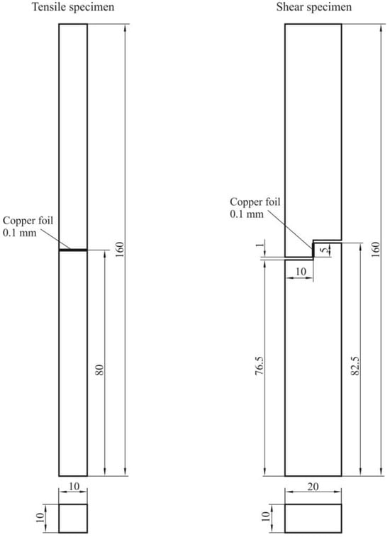
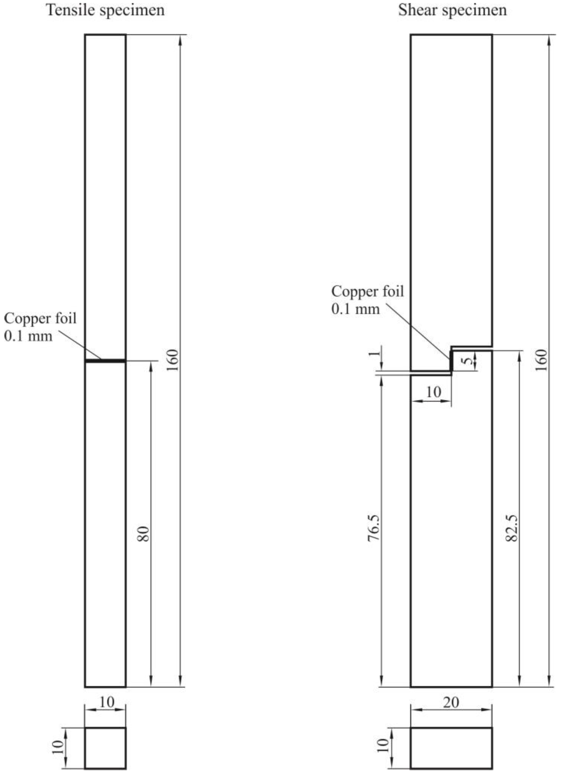
The tensile and shear specimens (see Figure 2) were prepared by milling from stainless steel 316L bars in the as-received condition. The chemical composition of the analysed steel (see Table 1) was determined using an Optical Emission Spectrometer (OES; Spectrolab LAS01, Spectro Analytical Instruments GmbH, Kleve, Germany) and a Carbon and Sulfur Analyser (Leco CS744, Leco Corporation, St. Joseph, Michigan). A pure copper (99.99%) foil, 0.1 mm thick, was used as the brazing material. The specimens were produced using vacuum brazing technology, employing a specially designed assembly. The complete procedure consisted of vacuuming, heating, melting, and cooling (see reference [33]). During the vacuum brazing process, the maximum temperature reached approximately 1140 °C, which is slightly above the melting temperature of copper.
Figure 2.
Tensile (left) and shear (right) specimen.
Table 1.
The chemical composition in wt.% of stainless steel 316L (1.4404).
2.2. Experimental Testing
Quasi-static and fatigue tests were conducted on a Vibrophore 100 (Zwick/Roell) testing machine at a room temperature of 20 °C. The quasi-static tensile and shear tests of the analysed brazed joints were performed using a mechanical extensometer at a displacement rate of 0.5 mm/min until final fracture of the specimen. In total, four quasi-static tensile tests and five quasi-static shear tests were carried out to establish the σ–ε and τ– ε diagrams.
For both tensile and shear loading, fatigue tests were performed under pulsating loading (load ratio R = 0.1) at approximately 98 Hz. The applied fatigue loading (i.e., stress amplitude) was selected so that all fatigue tests remained in the high-cycle fatigue (HCF) regime, meaning that the yield stress was not exceeded in any individual test. The final fracture of the specimen was defined as the failure criterion.
Based on these conditions, 24 tensile fatigue tests and 17 shear fatigue tests were conducted at different stress amplitudes (the runout limit was set at 107 loading cycles). The tensile stress amplitude σₐ varied between 60 and 90 MPa, while the shear stress amplitude τₐ varied between 20 and 50 MPa. The results were used to generate the σₐ–N (tensile loading) and τₐ–N (shear loading) curves for the analysed brazed joints.
2.3. Metallographic and Fractographic Investigations
Metallographic and fractographic investigations were carried out for brazed samples prior to quasi-static and fatigue testing, and brazed samples after dynamic testing (separate examinations were performed for the tensile and shear specimens). The samples were prepared by hot-mounting in a thermoplastic resin, followed by grinding with SiC abrasive paper and multi-stage polishing with diamond suspensions. Selected samples were chemically etched using a solution composed of 37 mL HCl, 6.3 g K2Cr2O7, and 12.5 mL distilled water. To reveal the microstructure of the austenite grains, colour etching was applied. The etchant consisted of 85 mL distilled water, 15 mL HCl, and 1 g K2S2O5. The etching time was 30 s.
The metallographically prepared specimens were examined using light microscopy (Olympus BX53M and SZ10 Olympus-Olympus, Tokyo, Japan) and scanning electron microscopy (SEM). SEM analyses were performed using Quanta 3D (FEI, Eindhoven, The Netherlands), and a JSM IT800 SHL (Jeol, Tokyo, Japan) equipped with an AZtecLive & Ultim Max (Oxford Analytical, Bicester, UK) EDS system. Imaging was conducted at 3 kV and 15 kV. Quantitative microstructural measurements were performed with PRECiV (Evident, Tokyo, Japan). The fracture surfaces of the quasi-static and fatigue-tested specimens were examined in detail using light microscopy and scanning electron microscopy.
3. Results and Discussions
3.1. Quasi-Static Tests
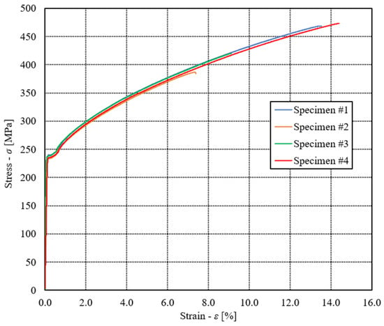
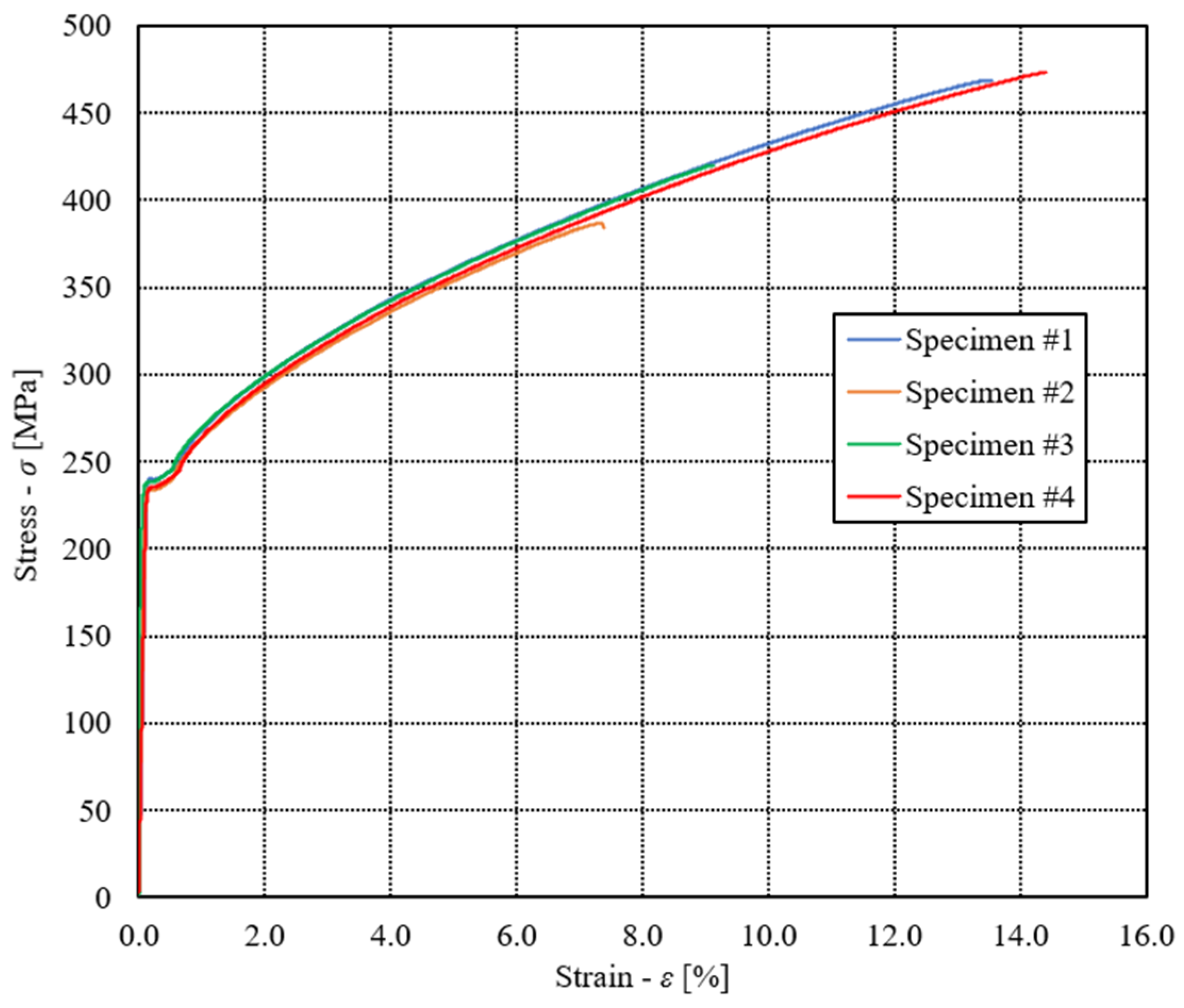
Figure 3 presents the σ–ε diagram for four quasi-static tensile tests. When interpreting these results, it should be noted that the total deformation of the tensile specimen arises from the combined deformation of the steel bar and the copper brazed joint. However, the volume of the copper layer is negligible compared with that of the surrounding steel, and its contribution to the overall deformation is therefore minimal. Consequently, the majority of the specimen’s elongation corresponds to deformation of the steel component. For this reason, the modulus of elasticity of the entire specimen is expected to be approximately equal to that of the base stainless steel (E ≈ 200 GPa; see Ref. [33] for the mechanical properties of the base material). This assumption does not apply to the yield stress and ultimate tensile strength. From Figure 3, the average yield stress is Re ≈ 237 MPa, which is higher than the yield stress of 316L stainless steel (≈202 MPa). Conversely, the average ultimate tensile strength of the analysed brazed joint, Rm ≈ 437 MPa, is lower than the ultimate tensile strength of the 316L steel (≈564 MPa). The experimental results indicate that vacuum brazing of 316L stainless steel with copper as the filler metal results in reductions in both strength and ductility. The brazed joint forms the weakest region of the specimen, and its average elongation at break (EL ≈ 11%) is significantly lower than that of the base 316L steel, which typically reaches about 56% [33].
Figure 3.
σ–ε diagram for four quasi-static tensile tests.
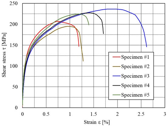
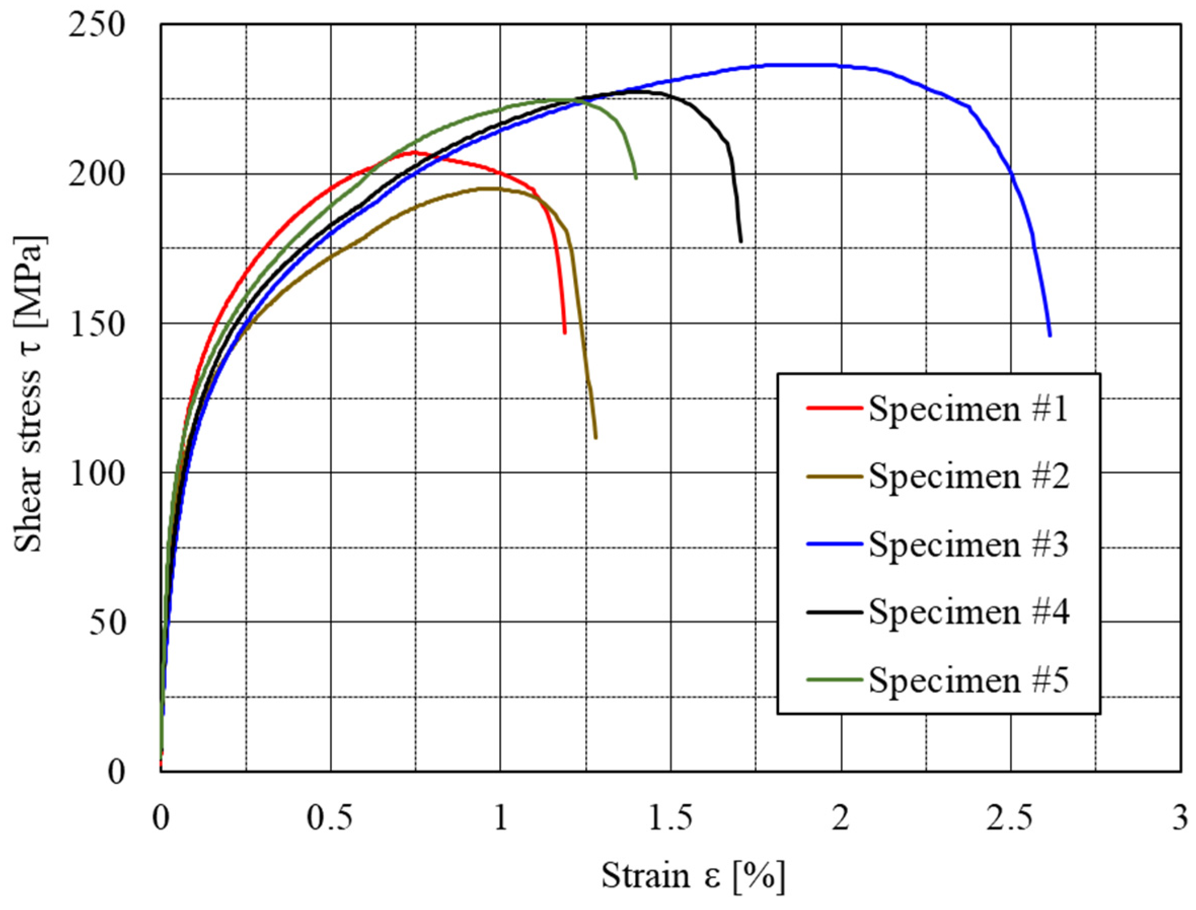
Figure 4 shows the t–ε diagram for five quasi-static shear tests. Here, it should be pointed out that the longitudinal normal strain e is presented against the shear stress t = F/A, obtained previously in regard to the external loading F and the brazed joint’s area A of the shear specimen (A = 5 × 10 = 50 mm2; see Figure 2 right). Although shear tests are commonly presented as τ–γ curves, a direct and reliable measurement of the shear strain γ in the brazed overlap region was not feasible in the present experimental configuration. Deformation is highly localised within the brazed joint, and the effective shear gauge length cannot be unambiguously defined. Furthermore, estimating γ from the crosshead displacement would be strongly influenced by the compliance of the loading train and the minor rotations inherent to the single-lap geometry, leading to an overestimation of the joint shear deformation and the introduction of bending contributions. Therefore, the longitudinal normal strain ε measured over the gauge length was adopted as the most robust and repeatable strain-related parameter. This approach provides a consistent basis for comparing the global deformation response and the onset of nonlinearity or damage among specimens, while the primary stress measure remains τ = F/A.
Figure 4.
t–ε diagram for five quasi-static shear tests.
Table 2 presents a comparison of the average mechanical properties of copper-brazed 316L stainless steel, as determined from tensile and shear tests. For reference, the mechanical properties of the base material (316L stainless steel) from our previous research [33] are also included. The brazing treatment can further homogenise and dissolve carbides in stainless steel, thereby increasing yield strength. The fracture of the brazed part occurred in the copper interlayer; thus, the tensile strength does not correspond to the properties of stainless steel but to those of the brazed joint, which represents the weakest region of the specimen. When comparing the tensile and shear ultimate strengths, it is evident that the latter is approximately half of the ultimate tensile strength. This ratio is, in a first-order sense, consistent with established ductile failure/yield criteria: under an idealised pure shear stress state, the Tresca criterion predicts τ ≈ σ/2, while the von Mises criterion predicts τ ≈ σ/√3. The present lap-shear configuration, however, does not generate a perfectly uniform pure shear field; stress concentrations at the overlap edges and secondary bending components due to load eccentricity lead to a mixed stress state. Consequently, failure initiates locally in the brazed joint—the weakest region—so the observed τu ≈ 0.5·σu should be interpreted as an effective joint-level relationship that remains broadly consistent with classical criteria, while also reflecting the non-uniform stress distribution inherent to the test geometry.
Table 2.
Average mechanical properties of copper-brazed stainless steel 316L obtained with quasi-static tensile test and shear test.
3.2. Fatigue Tests
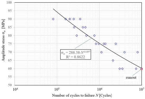
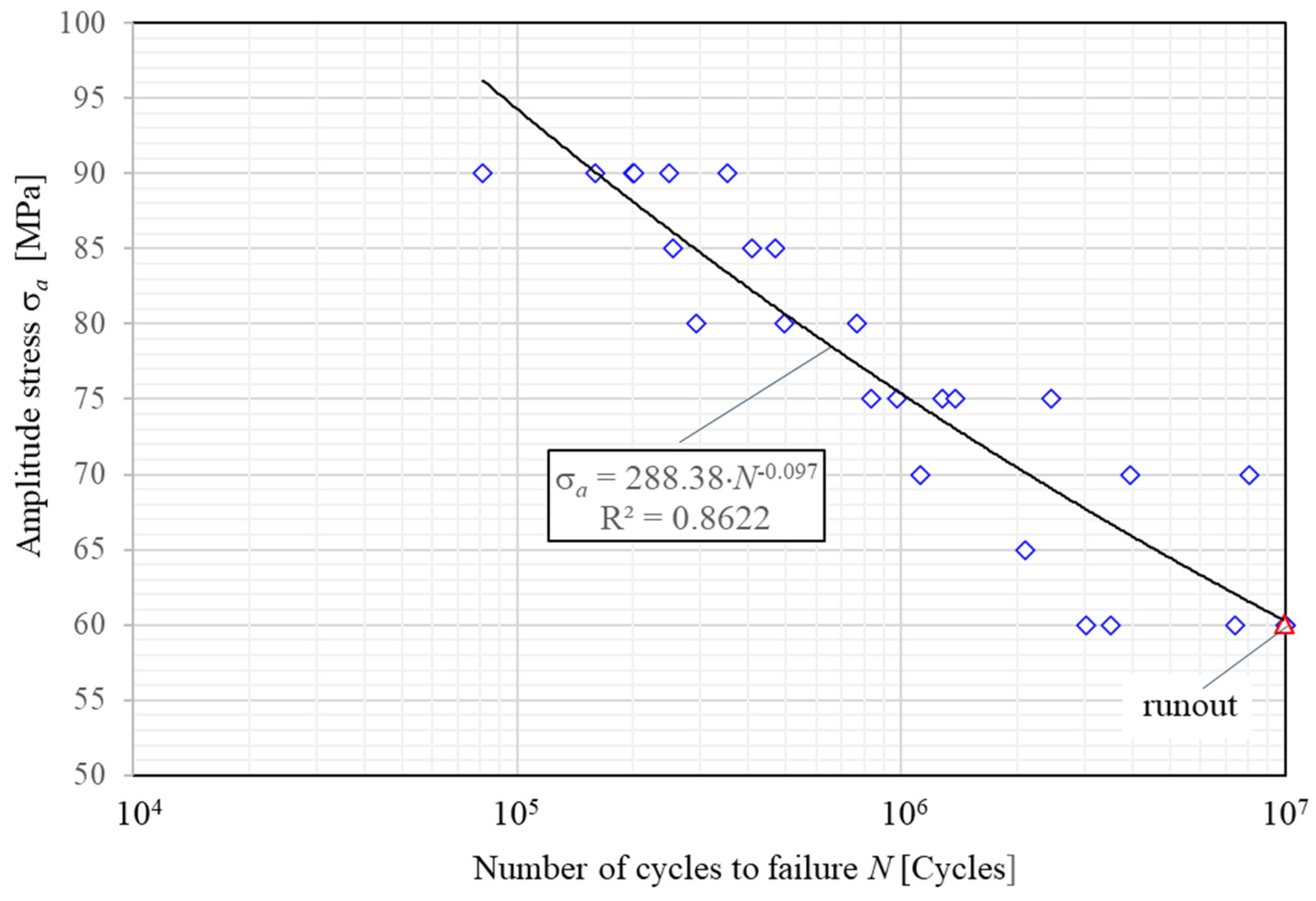
Figure 5 shows the σₐ–N plot (amplitude tensile stress σₐ versus number of cycles to failure N) for all 24 fatigue tests performed at stress amplitudes ranging from 60 to 90 MPa, while maintaining a constant load ratio of R = 0.1. The correlation line (black curve in Figure 5), representing the experimental results at a 50% probability of failure, can be expressed mathematically by the following equation:
where σf′ is the fatigue strength coefficient and b is the fatigue strength exponent. By comparing Equation (1) with the mathematical expression describing the fatigue life curve in Figure 5, the following material fatigue properties were obtained: σf′ = 288.38 MPa and b = −0.097.
Figure 5.
The diagram σₐ–N for tensile fatigue loading.
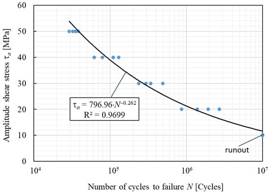
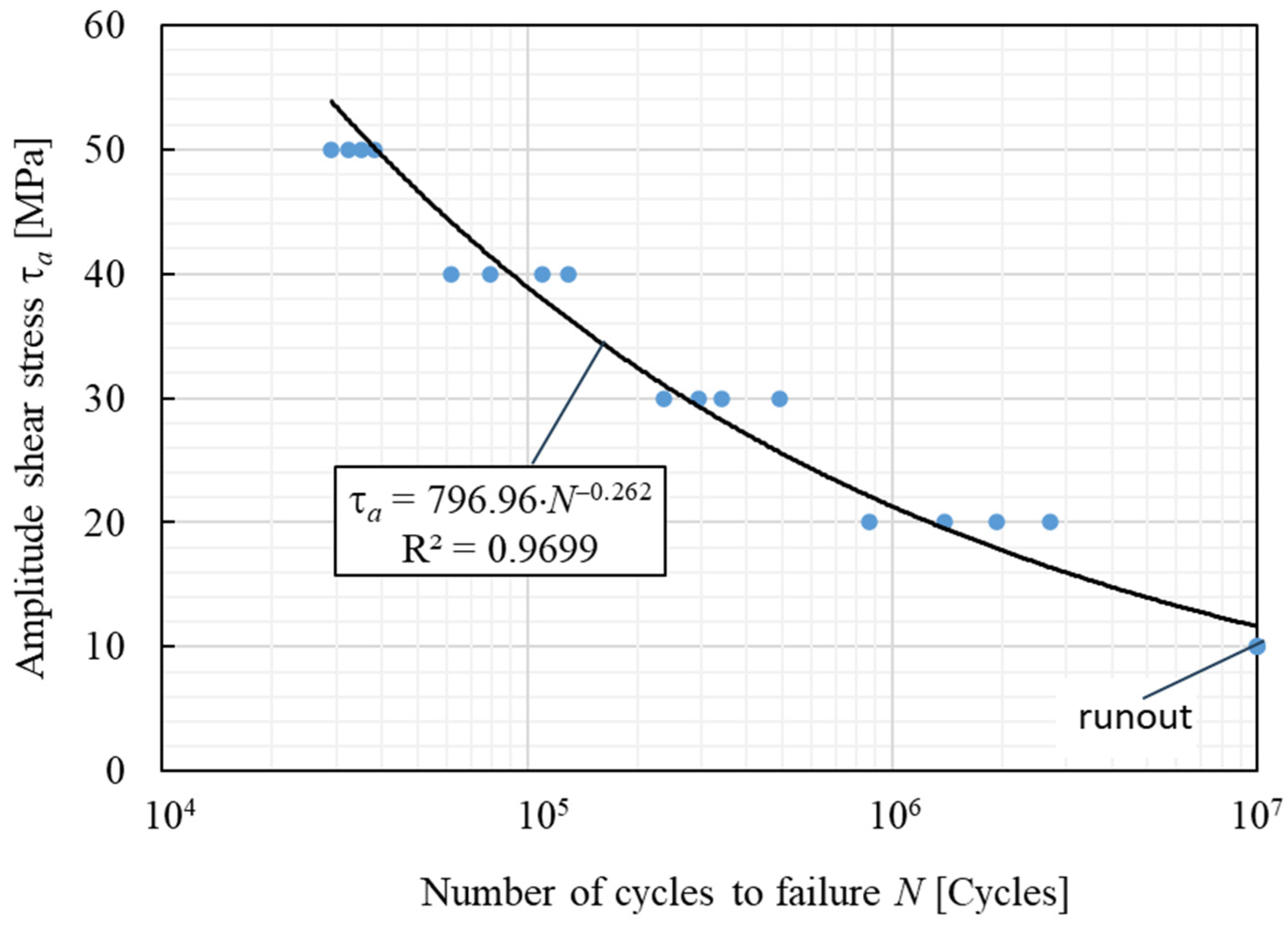
Figure 6 shows the τₐ–N plot (amplitude shear stress τₐ versus number of cycles to failure N) for all 17 fatigue tests performed at stress amplitudes ranging from 20 to 50 MPa, while maintaining a constant load ratio of R = 0.1. The correlation line (black curve in Figure 6), representing the experimental results at a 50% probability of failure, can be expressed mathematically by the following equation:
where τf′ is the shear fatigue strength coefficient and bs is the shear fatigue strength exponent. By comparing Equation (2) with the mathematical expression describing the fatigue life curve in Figure 6, the following material fatigue properties were obtained: τf′ = 796.96 MPa and bs = −0.262.
Figure 6.
The diagram τₐ–N for shear fatigue loading.
By comparing the σₐ–N (tensile loading) and τₐ–N (shear loading) fatigue life curves shown in Figure 5 and Figure 6, it can be concluded that the shear fatigue strength is significantly lower than the tensile fatigue strength. For example, at a prescribed fatigue life of N = 3 × 10⁵ cycles, the corresponding fatigue strength is approximately 85 MPa under tensile loading, whereas it is only about 30 MPa under shear loading. Furthermore, the steeper slope of the fatigue life curve under shear loading (bₛ = −0.262 for shear loading, compared to b = −0.097 for tensile loading) indicates a higher sensitivity to stress amplitude and a more pronounced reduction in fatigue life with increasing stress in shear. This behaviour is likely related to the formation of voids ahead of the main crack, which is more pronounced under shear loading (see Section 3.3). In addition, the thicker copper layer observed in the shear specimens may facilitate easier crack propagation at lower stress levels. However, the experimental results obtained for both tensile and shear fatigue strength can be applied to various practical applications when dimensioning dynamically loaded stainless-steel machine parts or structural elements, including copper-brazed joints.
3.3. Metallographic Investigation
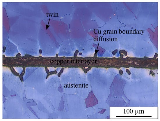
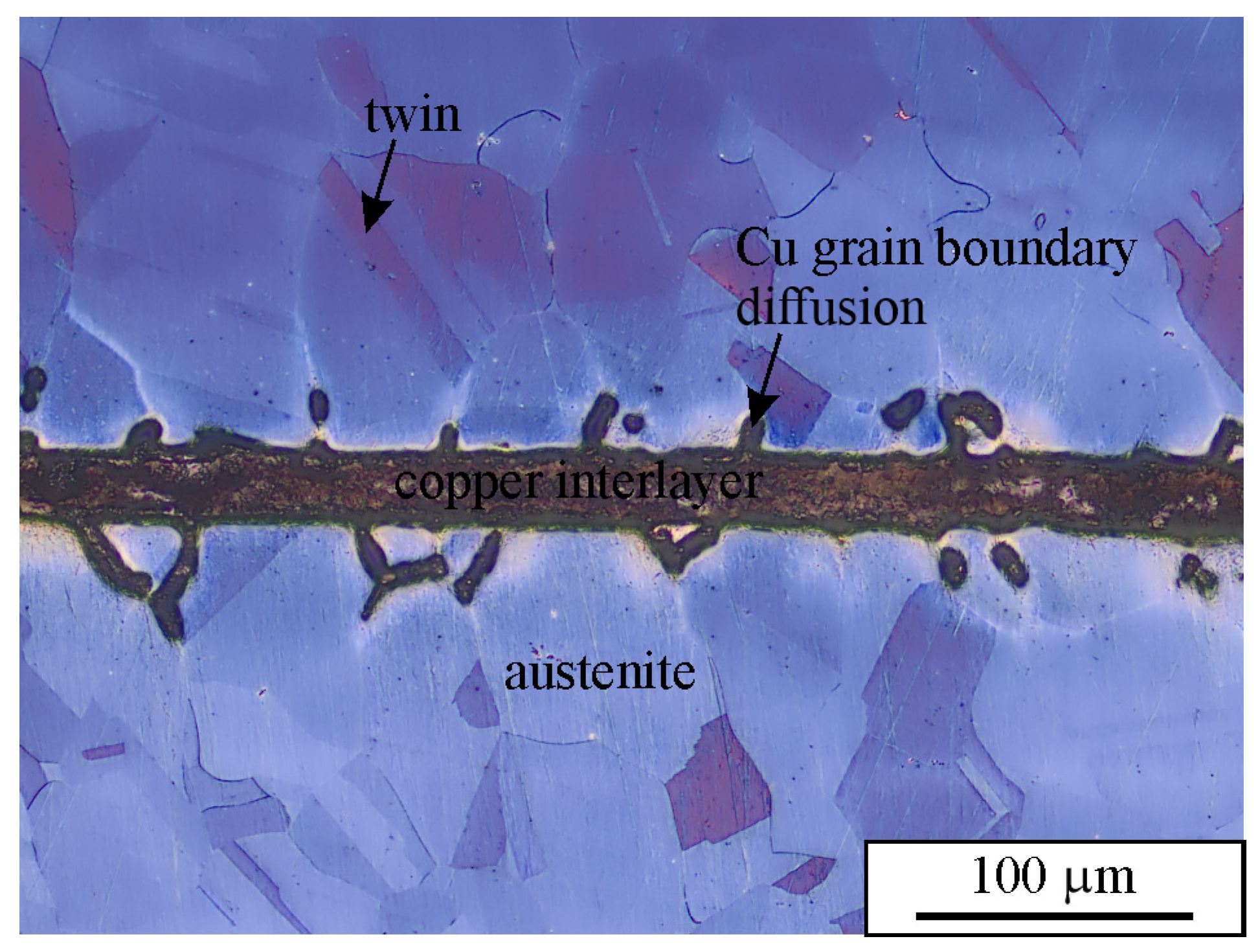
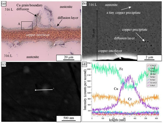
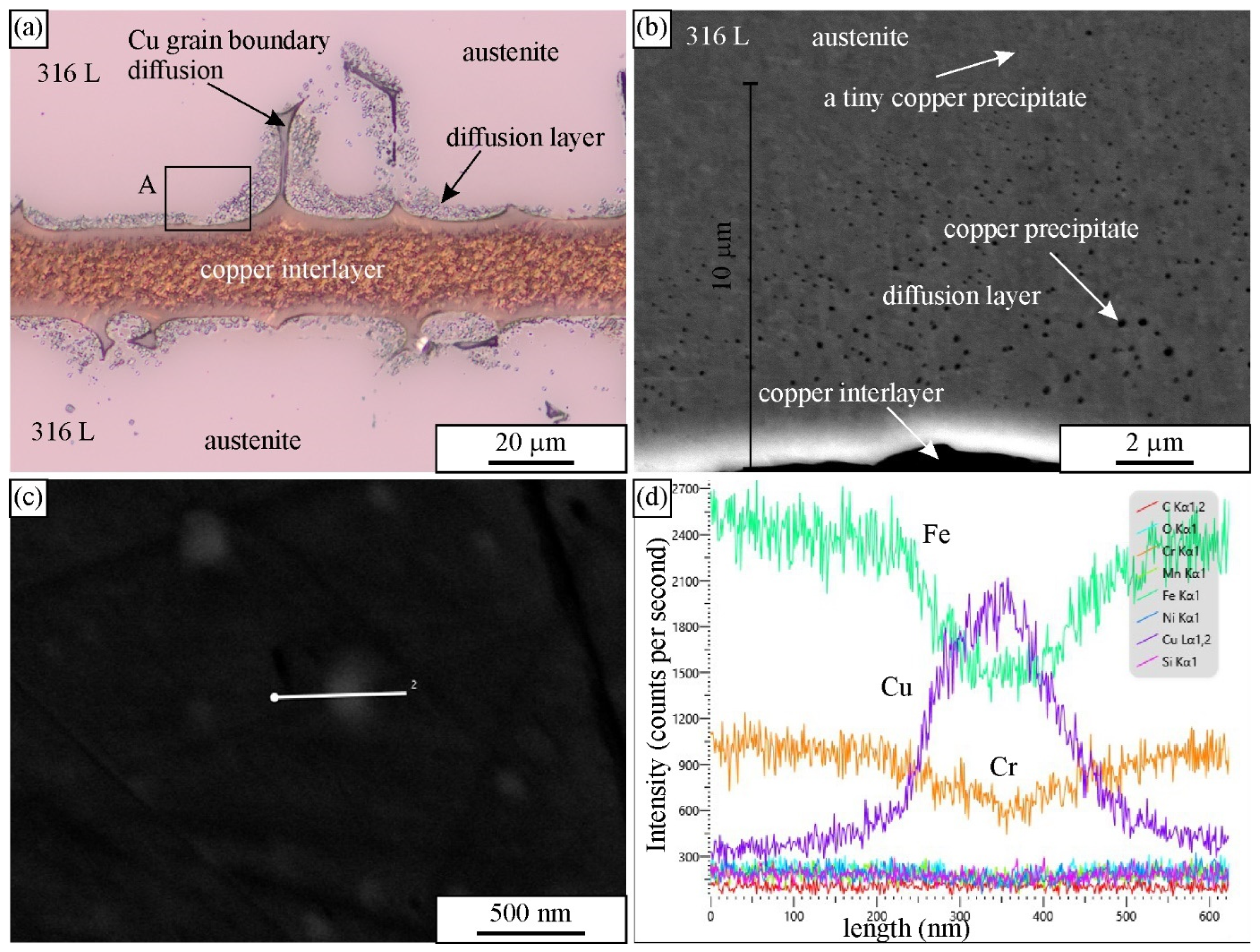
Figure 7 shows a typical brazed joint in a shear specimen, consisting of a copper interlayer, a diffusion zone, and the stainless-steel base material (316L). Prolonged exposure to elevated temperatures did not cause excessive growth of the austenite grains. Colour etching revealed several twins within the austenite grains. The thickness of the copper layer was uniform, and copper penetration into the steel along grain boundaries was observed. Colour etching caused the apparent thickness of the copper layer to appear greater than its actual value. Lighter etching revealed that the thickness of the copper interlayer was approximately 20–25 µm (Figure 8a).
Figure 7.
Light micrograph of the copper brazed joint, etched to reveal austenite grain boundaries.
Figure 8.
Microstructure of the brazed joint. (a) Light micrograph, (b) secondary electron micrograph (the micrograph corresponds to the area A in (a)), (c) line analysis of a single Cu precipitate (electron backscattered image), (d) elemental EDS line profile (different colours correspond to different elements in the legend).
In tensile specimens, the copper interlayer was approximately 8 µm thick, covering most of the contact region between the stainless steel components. Copper is fully liquid at the brazing temperature, whereas the stainless steel remains in the austenitic phase [34]. Thus, Fe and other alloying elements in steel dissolve into the molten copper, while copper simultaneously diffuses into the steel, both in the matrix as well as along grain boundaries. A copper diffusion layer was observed throughout, indicating that any oxide layers on the steel surface do not hinder copper diffusion into the steel. Copper diffuses into the substrate material up to 60 µm along grain boundaries. Diffusion also occurs into the crystal grains; the typical penetration depth is up to 10 µm (Figure 8b). Copper atoms are of similar size to iron atoms, so they form a substitutional solid solution. Copper atoms tend to attract vacancies, facilitating their movement through the steel lattice. However, the nickel atoms have even higher Ni-vacancy binding energy, which increases the migration barrier for copper, thereby reducing its diffusion rate [35]. The calculated penetration depth of Cu into bulk steel is about 6 mm, which is slightly less than the diffusion layer thickness. The diffusion coefficient of copper in austenite is 9.4 × 10⁻¹⁶ m2/s for the bulk diffusion [36]. The solubility of copper in austenite is estimated to be around 2 wt.%, and it decreases steeply with decreasing temperature [37]. This leads to the precipitation of copper-rich precipitates during cooling [38]. At the interface between the stainless steel and the Cu layer, there is an initial region approximately 1–2 µm thick that remains free of fine precipitates. Beyond this interface, a zone containing fine precipitates extended up to 10 µm into the stainless steel, with decreasing precipitate size. EDS analysis shows that only Cu is enriched in the precipitate (Figure 8c). The electron and characteristic X-ray volumes exceed the precipitate volume. Hence, a signal from the matrix is also present.
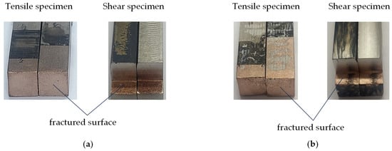
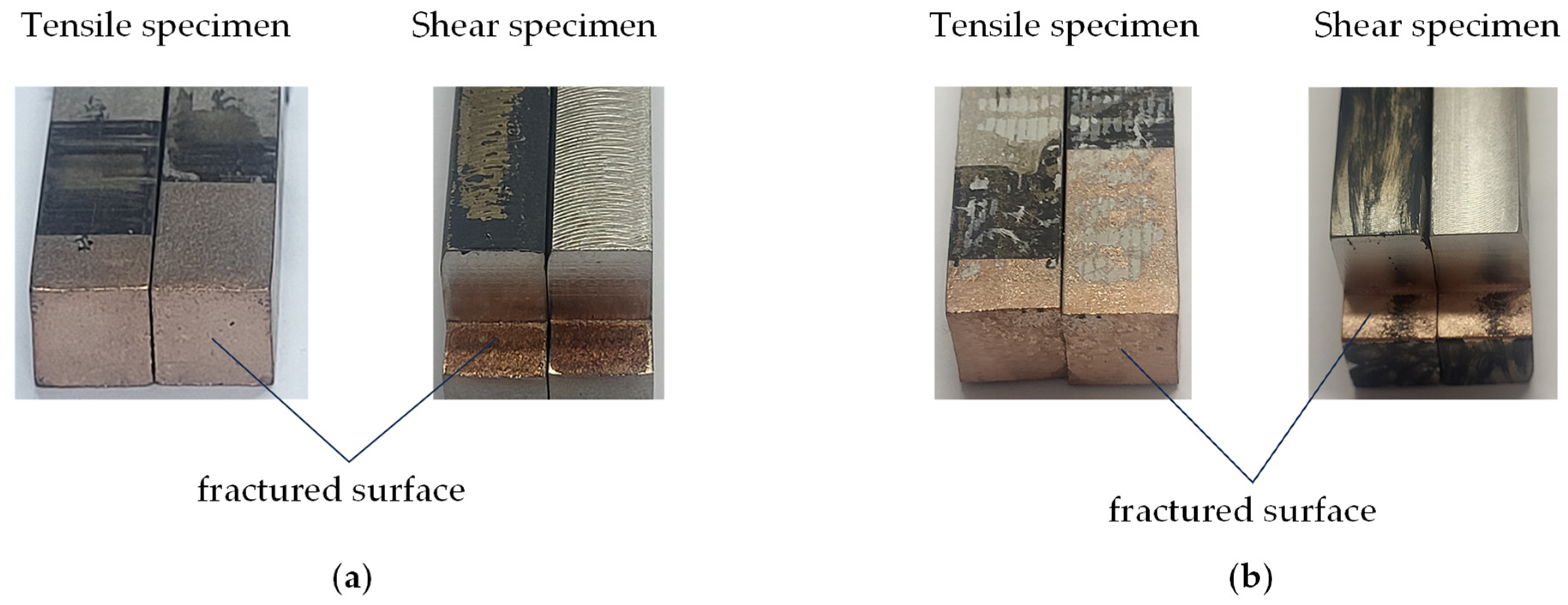
Figure 9 presents the macroscopic appearance of the fracture surfaces formed under quasi-static and fatigue loading. In all cases, the failure occurred predominantly within the copper layer of the brazed joint. A more detailed fractographic analysis of the joint is provided in the following sections.
Figure 9.
Macroscopic presentation of fractured surfaces by quasi-static loading (a) and fatigue loading (b).
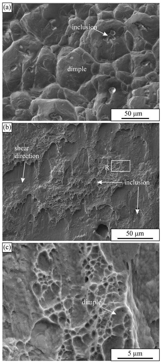
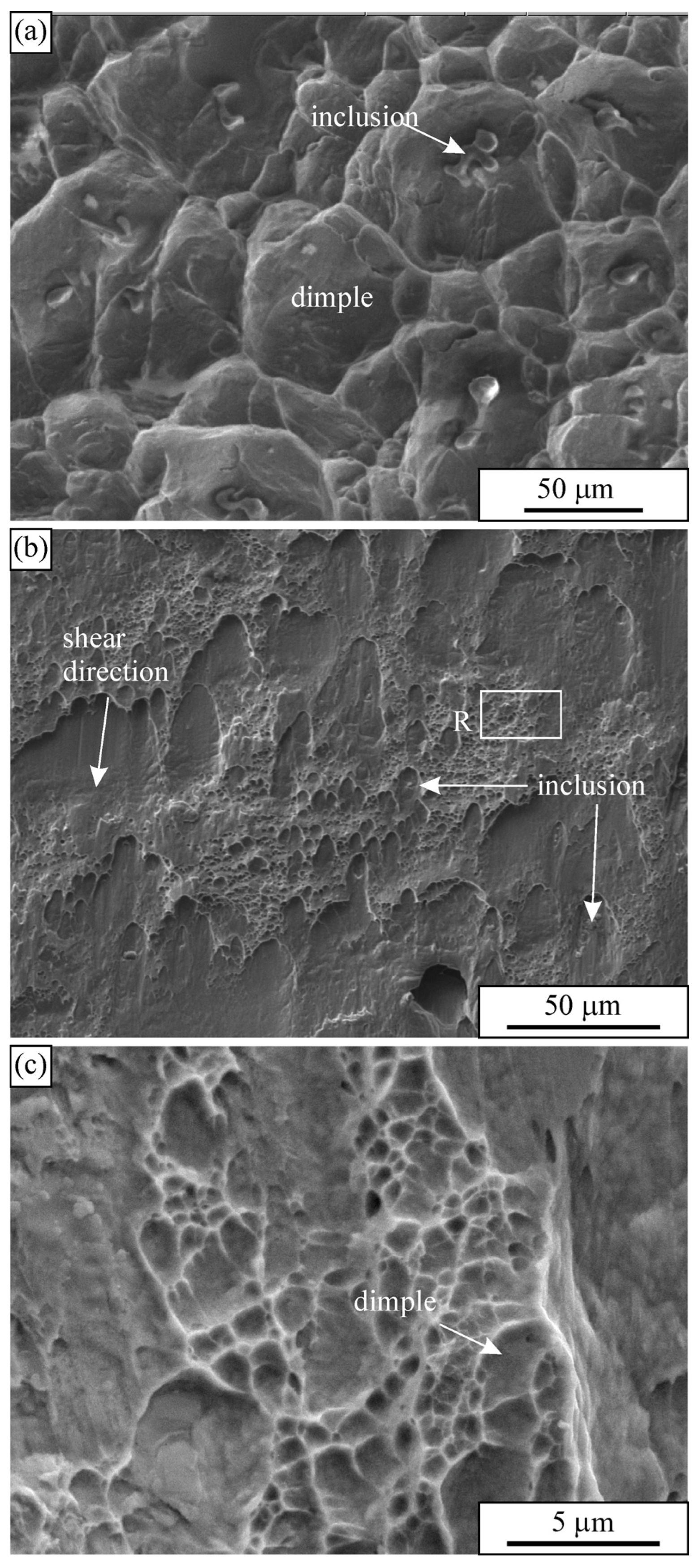
Figure 10a shows the fracture surface of a quasi-static tensile specimen. The fracture was ductile and lay entirely within the copper interlayer. The linear intercept length of dimples was about 16 mm. Typically, they formed at harder inclusions, and grew relatively uniformly in all directions. It should be stated that the dimples at the fracture surface of the bare stainless steel were much smaller (see reference [33]). On the other hand, the fracture surface of a shear specimen was characterised by long flat bands, oriented in the direction of shear stress (Figure 10b). At the onset of plastic deformation, voids formed at hard inclusions; however, their growth was not uniform in all directions but predominantly along the shear direction, resulting in ellipsoidal shapes. These voids continued to grow and eventually coalesced with neighbouring voids, producing a characteristic parabolic morphology on the fracture surface. Only in relatively thin regions between the bands (corresponding to the former ellipsoidal voids) were circular dimples observed, which likely formed during the final fracture of the specimen (Figure 10c).
Figure 10.
Secondary electron micrographs of fracture surfaces of quasi-static specimens. (a) Quasistatic-tensile specimen, (b) quasi-static shear specimen, and (c) region R in (b).
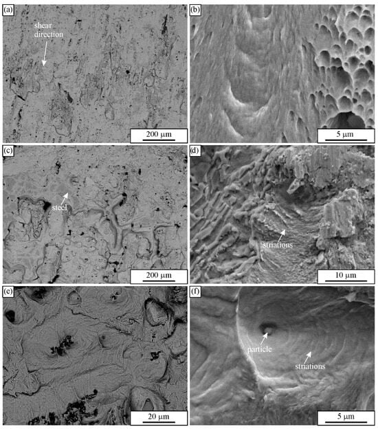
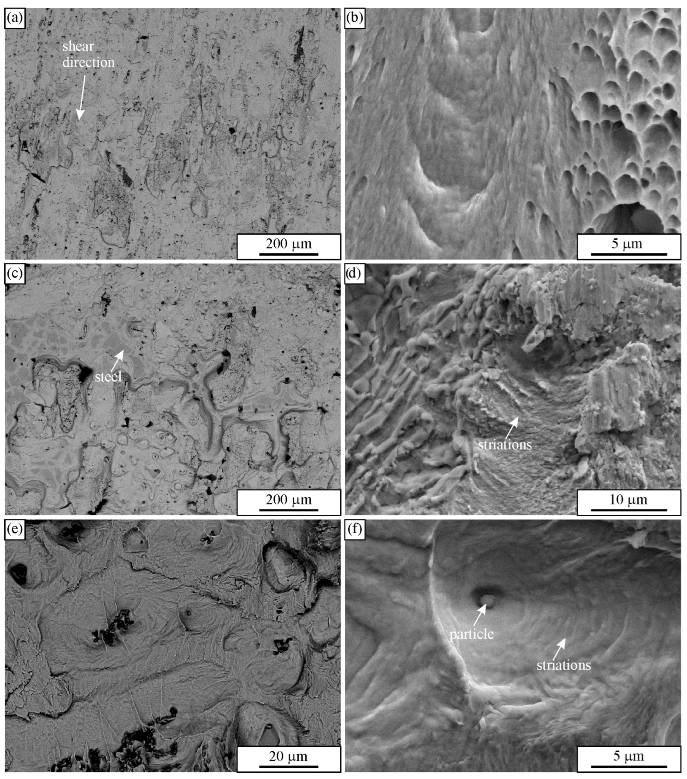
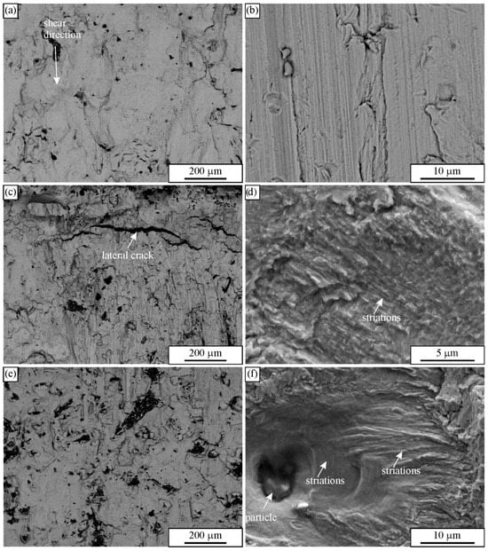
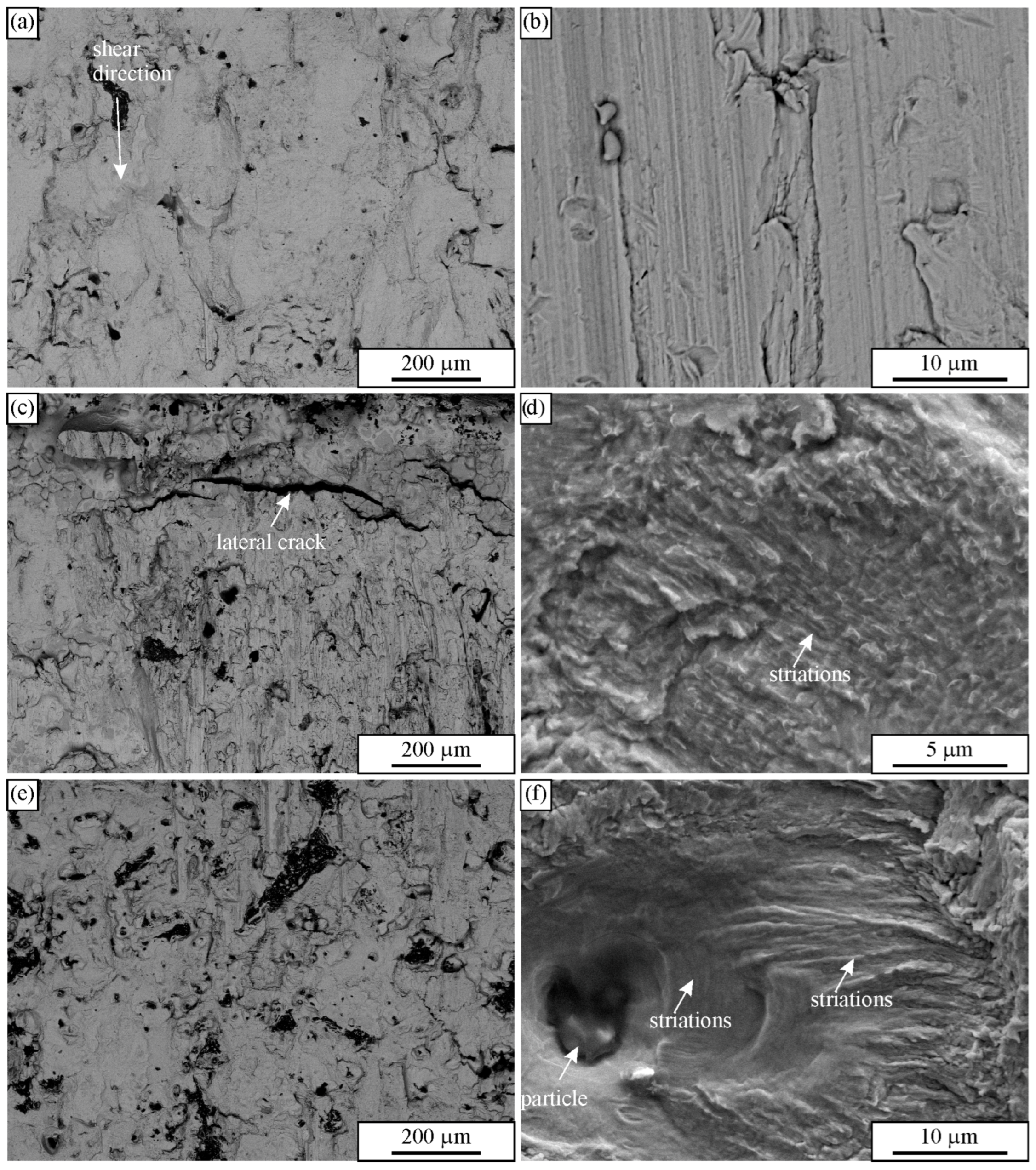
The fractography study was conducted for low-cycle fatigue (amplitude stress of 50 MPa) and the high-cycle fatigue regime (20 MPa). The micrographs were taken at 0.5 and 3 mm from the crack start, as well as in the region of forced fracture. The copper interlayer was thicker in shear specimens than in the tensile specimens. Correspondingly, the crack propagated mainly within the copper interlayer. On the other hand, the crack in tensile fatigue specimens often propagated through the diffusion layer as well [33]. Figure 11 and Figure 12 show the fracture surfaces of the shear fatigue specimens. The fracture started at an overlapping point between the two parts. The crack propagated in the shear direction. The fracture surfaces were relatively smooth at short distances from the crack start (Figure 11a,b and Figure 12a,b). They highly resemble the fracture surface of a quasi-static shear specimen, especially the specimen at the amplitude stress 50 MPa, where, between flat surfaces, dimples can be seen (Figure 11b). In the central part of the tensile fatigue specimens, striations were clearly observed since the crack tip was repeatedly opened and closed. However, there is no such opening and closing during shear loading, thus the striations were less pronounced. Nevertheless, there were some marks resembling the striations, indicating a crack propagation step in each cycle (Figure 11d and Figure 12d). There were some lateral cracks on the fracture surface at a lower stress amplitude (Figure 12c). In the regions of forced fracture, a higher stress amplitude led to unstable crack propagation. The fracture surface becomes rougher (Figure 11e,f and Figure 12e,f). In front of the advancing fatigue crack, voids formed around the hard defects and grew into circular shapes. In this area, there were not so many differences between tensile and shear fatigue specimens.
Figure 11.
Fracture surface of a fatigue shear specimen after low-cycle fracture (amplitude stress 50 MPa, fracture after 4 × 10⁴ cycles. (a,b) 0.5 mm from the crack start, (c,d) 3 mm from the crack start, and (e,f) in the area of the final forced fracture.
Figure 12.
Fracture surface of a fatigue shear specimen after high-cycle fracture (amplitude stress 20 MPa, fracture after 1.5 × 10⁶ cycles. (a,b) 0.5 mm from the crack start, (c,d) 3 mm from the crack start, and (e,f) in the area of the final forced fracture.
4. Conclusions
The present study investigates the quasi-static and fatigue strength of copper-brazed AISI 316L stainless steel. Two types of specimens (tensile and shear) were prepared to determine the stress–strain response and the corresponding fatigue life (S–N) curves. Based on the experimental results and a comprehensive metallographic investigation, the following conclusions can be drawn:
- (i)
- Metallographic analysis revealed the presence of inclusions, likely formed during the vacuum brazing process. Since the dimple size in the copper interlayer is influenced by the number and distribution of larger inclusions, a more detailed investigation of the brazed joint microstructure is recommended for future studies.
- (ii)
- Quasi-static tests indicate that vacuum brazing reduces the tensile strength of the base material, as the brazed joint represents the weakest region of the specimen. A comparison of the ultimate strengths shows that the ultimate shear strength is approximately half of the ultimate tensile strength. On the other hand, the brazing thermal cycle may promote carbide dissolution and microstructural homogenisation in the stainless steel, leading to an increase in yield strength. The fatigue tests reveal that the shear fatigue strength is significantly lower than the tensile fatigue strength.
- (iii)
- Fractographic analysis of both quasi-static and fatigue specimens revealed that crack propagation predominantly occurs within the copper interlayer. Therefore, the diffusion zone and the precipitate-free zone do not significantly influence the overall mechanical properties. Although the initial copper foil thickness was identical for both tensile and shear specimens, the resulting copper interlayer thickness after vacuum brazing differed, measuring approximately 20–25 µm in the shear specimens and about 8 µm in the tensile specimens. Fractographic analysis of quasi-static specimens indicates that shear fracture surfaces are characterised by long, flat bands oriented in the direction of the applied shear stress. Dimples are formed only in thin regions between these bands, whereas tensile specimens exhibit large dimples distributed over the entire fracture surface. Fractographic analysis of fatigue specimens shows that in shear fatigue specimens, fatigue cracks propagate predominantly within the copper interlayer. Crack initiation occurs at the overlap region between the joined parts, followed by propagation in the shear direction. Near the crack initiation site, the fracture surfaces are relatively smooth and closely resemble those observed in quasi-static shear specimens. In tensile fatigue specimens, well-defined striations are observed in the central region of the fracture surface. Due to the absence of crack opening and closing during shear loading, striations are less pronounced in shear fatigue specimens; however, some features resembling striations can still be identified, suggesting incremental crack growth during each loading cycle. In regions of final forced fracture, no significant differences are observed between tensile and shear fatigue specimens.
- (iv)
- Detailed metallographic analyses, together with quasi-static and fatigue tests, provide valuable input for the design and optimisation of copper-brazed structural components such as plate heat exchangers. Furthermore, the experimentally obtained tensile and shear fatigue data are relevant to practical engineering applications, particularly for the dimensioning of dynamically loaded stainless-steel machine parts and structural elements incorporating copper-brazed joints.
Author Contributions
Conceptualisation, S.G. and F.Z.; methodology, S.G. and F.Z.; software, T.B.; validation, S.G., F.Z. and T.B.; formal analysis, B.N. and Ž.D.; investigation, B.N. and Ž.D.; writing—original draft preparation, T.B., B.N. and Ž.D.; writing—review and editing, S.G. and F.Z.; supervision, S.G.; project administration, F.Z.; funding acquisition, S.G. and F.Z. All authors have read and agreed to the published version of the manuscript.
Funding
The authors acknowledge the financial support of the Research Core Funding (No. P2-0063, No. P2-0120 and I0-0029) and Basic Postdoc Research Project (No. Z2-50082) from the Slovenian Research and Innovation Agency.
Institutional Review Board Statement
Not applicable.
Data Availability Statement
The original contributions presented in the study are included in the article; further inquiries can be directed to the corresponding author.
Acknowledgments
The authors also acknowledge the use of research equipment, a “High-frequency pulsator”, a “Hardness, microhardness and indentation tester and “FEG SEM Jeol JSM IT800 SHL” within the project “Upgrading national research infrastructures—RIUM”, which was co-financed by the Republic of Slovenia, the Ministry of Education, Science and Sport and the European Union from the European Regional Development.
Conflicts of Interest
The authors declare no conflicts of interest.
References
- Swathi Kiranmayee, M.; Jha, A.K.; Manwatkar, S.K.; Sudhakar, D.P.; Ramesh Narayanan, P.; Sreekumar, K.; Sinha, P.P. Microstructural Characterisation of Copper-Stainless Steel Brazed Joint with Copper Based Filler Metal. Mater. Sci. Forum 2012, 710, 650–655. [Google Scholar] [CrossRef] [Scilit]
- Li, Y.; Parfitt, D.; Flewitt, P.E.J.; Hou, X.; Quinta de Fonseca, J.; Chen, B. Microstructural Considerations of Enhanced Tensile Strength and Mechanical Constraint in a Copper/Stainless Steel Brazed Joint. Mater. Sci. Eng. A 2020, 796, 139992. [Google Scholar] [CrossRef] [Scilit]
- Varanasi, D.; Koncz-Horvath, D.; Sycheva, A.; Baumli, P.; Kaptay, G. Cracking of Copper Brazed Steel Joints Due to Precipitation of MnS upon Cooling. J. Mater. Eng. Perform. 2020, 29, 8183–8193. [Google Scholar] [CrossRef] [Scilit]
- Roy, R.K.; Ghosh, M. Advancement of Brazing Filler Alloy: An Overview. In Joining Processes for Dissimilar and Advanced Materials; Elsevier: Amsterdam, The Netherlands, 2022; pp. 553–579. [Google Scholar]
- Luo, Q.; Xue, S.; Wu, J. Influences of Sn on Properties of Ag-Based and Cu-Based Brazing Filler Metals. Crystals 2021, 11, 1403. [Google Scholar] [CrossRef] [Scilit]
- Song, R.; Schroth, J.G.; Speer, J.G.; Matlock, D.K. Copper Brazing Response of Some Advanced High Strength Steel Grades. J. Mater. Process. Technol. 2009, 209, 70–76. [Google Scholar] [CrossRef] [Scilit]
- Siqueira, L.O.; da Silva, A.C.S.; Marques, I.J.; Gonzalez, C.H.; de Abreu Santos, T.F. Microstructural Evaluation of Copper Brazed Joints Using Silver-Based Filler Metal. Metallogr. Microstruct. Anal. 2021, 10, 174–183. [Google Scholar] [CrossRef] [Scilit]
- Remešová, M.; Klakurková, L.; Skalka, P.; Gejdoš, P.; Juliš, M.; Čelko, L. Failure Analysis of Copper Heating Blocks Designed for Brazing Sheets. Eng. Fail. Anal. 2025, 178, 109718. [Google Scholar] [CrossRef] [Scilit]
- Ravi Teja, J.B.; Pavan Kalyan, K.; Vaira Vignesh, R.; Govindaraju, M. Vacuum Brazing of Mild Steel Using Eutectic CuSil Brazing Alloy. Mater. Today Proc. 2021, 46, 4919–4924. [Google Scholar] [CrossRef] [Scilit]
- Mehdikhani, H.; Mostafapour, A.; Binesh, B. Mechanical Properties and Microstructure of the C70600 Copper-Nickel Alloy and C46500 Brass Joint Using Brazing Technique. J. Adv. Join. Process. 2025, 11, 100294. [Google Scholar] [CrossRef] [Scilit]
- Uhlig, T.; Fedorov, V.; Elßner, M.; Wagner, G.; Weis, S. Reduction of Liquid Metal Embrittlement in Copper-Brazed Stainless Steel Joints. IOP Conf. Ser. Mater. Sci. Eng. 2017, 181, 012032. [Google Scholar] [CrossRef] [Scilit]
- Habibi, F.; Mostafapour, A.; Heydarpour, K. Microstructural Evaluation and Mechanical Properties of WC-6%Co/AISI 1045 Steel Joints Brazed by Copper, Brass, and Ag-Based Filler Metals: Selection of the Filler Material. J. Adv. Join. Process. 2024, 9, 100212. [Google Scholar] [CrossRef] [Scilit]
- Silze, F.; Wiehl, G.; Kaban, I.; Wendrock, H.; Gemming, T.; Kühn, U.; Eckert, J.; Pauly, S. Wetting Behaviour of Cu–Ga Alloys on 304L Steel. Mater. Des. 2016, 91, 11–18. [Google Scholar] [CrossRef] [Scilit]
- Izaguirre, I.; de Prado, J.; Sánchez, M.; Ureña, A. Wettability and Microstructural Evolution of Copper Filler in W and EUROFER Brazed Joints. Int. J. Adv. Manuf. Technol. 2024, 131, 5905–5921. [Google Scholar] [CrossRef] [Scilit]
- Lemma, E.A.; Dias, J.M.S.; Bastos, A.; Mascate, B.; Horovistiz, A. Advances in Induction Brazing of Copper and Dissimilar Metals: Challenges and Emerging Trends. J. Adv. Join. Process. 2025, 11, 100302. [Google Scholar] [CrossRef] [Scilit]
- Pereira, A.B.; Dias, J.M.S.; Rios, J.P.; Silva, N.M.; Duraisamy, S.; Horovistiz, A. Brazing of Copper Pipes for Heat Pump and Refrigeration Applications. Metals 2024, 14, 171. [Google Scholar] [CrossRef] [Scilit]
- Zhang, J.; Zhu, X.; Mondejar, M.E.; Haglind, F. A Review of Heat Transfer Enhancement Techniques in Plate Heat Exchangers. Renew. Sustain. Energy Rev. 2019, 101, 305–328. [Google Scholar] [CrossRef] [Scilit]
- Abou Elmaaty, T.M.; Kabeel, A.E.; Mahgoub, M. Corrugated Plate Heat Exchanger Review. Renew. Sustain. Energy Rev. 2017, 70, 852–860. [Google Scholar] [CrossRef] [Scilit]
- Borjigin, S.; Zhao, W.; Fu, W.; Liang, W.; Bai, S.; Ma, J.; Meng, K.; Baoyin, H. Review of Plate Heat Exchanger Utilised for Gases Heat Exchange. Renew. Sustain. Energy Rev. 2025, 210, 115224. [Google Scholar] [CrossRef] [Scilit]
- Singh, R.; Pant, K.K.; Lal, S.; Yadav, D.P.; Garg, S.R.; Raghuvanshi, V.K.; Mundra, G. Vacuum Brazing of Accelerator Components. J. Phys. Conf. Ser. 2012, 390, 012025. [Google Scholar] [CrossRef] [Scilit]
- Vetrivendan, E.; Varghese, P.; Krishnan, R.; Mathews, T.; Ningshen, S. Vacuum Brazing of Copper and SS316L Using Ni–P Eutectic Alloy Filler for Nuclear Applications. Weld. World 2022, 66, 2041–2052. [Google Scholar] [CrossRef] [Scilit]
- Mangla, V.; Sharma, J.D.; Kumar, S.; Dinesh Kumar, P.; Agarwal, A. Joining of Stainless Steel (SS304) and OFE Copper by Vacuum Brazing. Mater. Today Proc. 2020, 26, 724–727. [Google Scholar] [CrossRef] [Scilit]
- Wang, Y.; Shang, Q.; Zeng, J.; Hou, A.; Wang, X.; Wang, Y. Vacuum Brazing and Performance Evaluation of T2 Copper Block and 316L Stainless Steel Tube. Metals 2023, 13, 1349. [Google Scholar] [CrossRef] [Scilit]
- Kozlova, O.; Voytovych, R.; Devismes, M.-F.; Eustathopoulos, N. Wetting and Brazing of Stainless Steels by Copper–Silver Eutectic. Mater. Sci. Eng. A 2008, 495, 96–101. [Google Scholar] [CrossRef] [Scilit]
- Lin, Q.; Ma, Z.; Sui, R. Wetting and Pressureless Infiltration Behavior of Cu/316L System at 1100 °C. Surf. Interfaces 2023, 42, 103462. [Google Scholar] [CrossRef] [Scilit]
- Shi, X.; Li, Y.; Bai, Y.; Zheng, X.; Yao, S.; Zhu, Z.; Chen, H. Effect of Ni in Pure Cu/304 Stainless Steel Induction Brazing Joints. Mater. Charact. 2021, 182, 111562. [Google Scholar] [CrossRef] [Scilit]
- Ghovanlou, M.K.; Jahed, H.; Khajepour, A. Mechanical Reliability Characterization of Low Carbon Steel Brazed Joints with Copper Filler Metal. Mater. Sci. Eng. A 2011, 528, 6146–6156. [Google Scholar] [CrossRef] [Scilit]
- Min, M.; Mao, Y.; Deng, Q.; Wang, G.; Wang, S. Vacuum Brazing of Mo to 316L Stainless Steel Using BNi-2 Paste and Cu Interlayer. Vacuum 2020, 175, 109282. [Google Scholar] [CrossRef] [Scilit]
- Hayta, Y.; Kandemir, S. Fatigue Assessment of Copper-Brazed Stainless-Steel Joints for Plate Heat Exchangers. Fatigue Fract. Eng. Mater. Struct. 2025, 48, 725–737. [Google Scholar] [CrossRef] [Scilit]
- Li, Y.; Zhang, X.; Parfitt, D.; Jones, S.; Chen, B. Characterisation of Microstructure, Defect and High-Cycle-Fatigue Behaviour in a Stainless Steel Joint Processed by Brazing. Mater. Charact. 2019, 151, 542–552. [Google Scholar] [CrossRef] [Scilit]
- Kralj, J.; Hanželič, B.; Glodež, S.; Kramberger, J.; Satošek, R.; Nečemer, B. Fatigue behaviour of copper-brazed 316L stainless steel. Mater. Tehnol. 2024, 58, 433–440. [Google Scholar] [CrossRef] [Scilit]
- Hanželič, B.; Kralj, J.; Bončina, T.; Nečemer, B.; Kramberger, J.; Satošek, R.; Glodež, S. Fatigue Behaviour of Brazed Joints for Heat Exchangers. Materials 2024, 17, 479. [Google Scholar] [CrossRef] [Scilit] [PubMed]
- Bončina, T.; Zupanič, F.; Nečemer, B.; Satošek, R.; Rihter, E.; Glodež, S. Fatigue and Fracture Characterisation of Copper-Brazed 316L Stainless Steel. Int. J. Fatigue 2026, 203, 109333. [Google Scholar] [CrossRef] [Scilit]
- William Gale, T.T. Smithells Metals Reference Book; Elsevier: Amsterdam, The Netherlands, 2003; ISBN 9780080480961. [Google Scholar]
- Mo, J.; Li, J.; Wu, P.; Feng, G. The Effects of Ni/Cr on Diffusion Behavior of Cu in 304 Stainless Steel. Vacuum 2024, 222, 112955. [Google Scholar] [CrossRef] [Scilit]
- Haubner, R.; Strobl, S.; Bichler, L.P.; Linhardt, P. Liquid Metal Embrittlement of Copper Brazed Plate Heat Exchangers. Key Eng. Mater. 2019, 809, 535–540. [Google Scholar] [CrossRef] [Scilit]
- Salje, G.; Feller-Kniepmeier, M. The Diffusion and Solubility of Copper in Iron. J. Appl. Phys. 1977, 48, 1833–1839. [Google Scholar] [CrossRef] [Scilit]
- Rivolta, B.; Gerosa, R. On the Non-Isothermal Precipitation of Copper-Rich Phase in 17-4 PH Stainless Steel Using Dilatometric Techniques. J. Therm. Anal. Calorim. 2010, 102, 857–862. [Google Scholar] [CrossRef] [Scilit]

Disclaimer/Publisher’s Note: The statements, opinions and data contained in all publications are solely those of the individual author(s) and contributor(s) and not of MDPI and/or the editor(s). MDPI and/or the editor(s) disclaim responsibility for any injury to people or property resulting from any ideas, methods, instructions or products referred to in the content. |
© 2026 by the authors. Licensee MDPI, Basel, Switzerland. This article is an open access article distributed under the terms and conditions of the Creative Commons Attribution (CC BY) license.