


Abstract
The bond–slip behavior between I-shaped steel and shotcrete crucially influences the cooperative deformation and overall bearing capacity of tunnel initial support. To clarify the bond–slip mechanism between the steel section and shotcrete, this study conducted push-out tests on five groups of stud-reinforced specimens, investigating the effects of stud geometry and arrangement. The tests revealed two primary failure modes—tensile and expansion failure—governed by stud quantity and strength. The typical bond–slip curve comprises four stages: non-slip, ascending, descending, and residual. The quantitative results highlight that stud arrangement and diameter significantly impact bearing capacity. The quincuncial layout achieved an ultimate load of 372.4 kN, which is 16.8% and 54.9% higher than that of the double-row (318.9 kN) and single-row (240.5 kN) parallel arrangements, respectively. Increasing the stud diameter from 13 mm to 16 mm boosted the ultimate load by 16.7% (from 240.5 kN to 280.7 kN). The residual load was approximately 62–87% of the ultimate load. Based on these findings, a bond–slip constitutive model was developed, showing high agreement with experimental data. This study provides theoretical support for optimizing steel–shotcrete support systems in tunnels, though generalizability is limited by sample size and the exclusion of long-term load effects.
1. Introduction
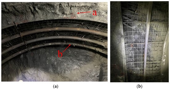
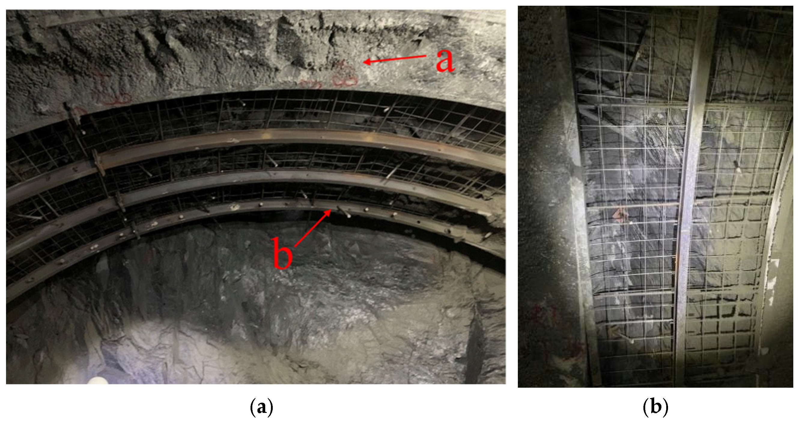
The initial support structure consisting of steel sets combined with shotcrete has been extensively adopted in tunnel engineering due to its convenient construction and rapid response characteristics, as shown in Figure 1 [1,2,3]. However, in areas with complex geological conditions, the conventional steel set–shotcrete composite support faces a critical limitation: the intrinsically smooth finish of steel components leads to weak mechanical interlock and limited inherent bond resistance between the steel and shotcrete, which is further reflected in deficient bond–slip performance at their interface [4,5,6].
Figure 1.
Steel–shotcrete initial support in tunnel (a—shotcrete; b—steel). (a) Tunnel support at vault. (b) Tunnel support at side walls.
When subjected to large surrounding rock loads, relative slippage tends to occur at the steel–shotcrete interface, which impairs the bonding effect and consequently leads to a significant reduction in the coordinated deformation capacity and combined load-bearing capacity of the initial support structure, thus making it difficult to achieve synchronous deformation and unified stress states [7,8].
Meanwhile, excessive interfacial slippage may further induce the cracking and local spalling of shotcrete, as well as the distortion of steel sets. These issues collectively weaken the overall load-bearing capacity of the initial support system and even induce instability and precipitate failure within the tunnel’s initial support system, thereby compromising the safety assurance of tunnel engineering projects [9,10,11]. Therefore, investigating strategies to enhance the bond–slip behavior between steel sets and shotcrete in tunnel support systems is of considerable importance.
In previous research, less attention was given to the construction with stud connections, which primarily focused on steel–concrete’s bonding behavior under natural bonding circumstances [12,13]. Corrugated steel plates, high-strength concrete, recycled concrete, and other materials were investigated by researchers to see how they affected bonding behavior [14,15,16]. Due to the benefits of their superior mechanical qualities, less resistance to reinforcing, and high construction quality, these materials have recently captured the interest of several academics, and research has been conducted on them. According to these experiments, the shear transfer was not significantly impacted by the studs on the steel section [17,18]. Xu et al. [19] and De Nardin et al. [20] suggested that shear connections may help to increase the bond resistance of steel tubes filled with concrete. According to their findings, the connections might significantly improve locally produced steel and concrete bonding capabilities. An experimental and numerical investigation of the bond–slip behavior of concrete and a corrugated steel plate with studs was conducted by Song et al. [21,22]. By examining specimens’ load–slip curve, bond strength, and interface damage energy dissipation, Dong et al. [23] derived the shear-bearing capacity equation and interface bond–slip constitutive relationship of studs under varied connections. By examining the stud connection’s failure mechanism and the UHPC–steel interface’s load–slip behavior, multiple investigations have developed analytical expressions for the shear resistance and corresponding load–slip response of embedded studs fabricated from ultra-high-performance concrete [24,25,26]. The push-out test performed by Wang et al. [27] considers the effect of screw position on bond–slip behavior, establishes a finite element model considering bond–slip interaction to characterize the interface behavior that cannot be measured in the push-out test, and further reveals the internal shear transfer mechanism. Zeng et al. investigated the push-out behavior of proband leister connectors (PBL connectors) in hybrid double-skin tubular members (DSTMs) and found that their shear-bearing capacity is mainly affected by concrete strength and the diameter of perforations [28,29].
In conclusion, studs can effectively characterize and enhance the bond behavior between in situ reinforcing steel and concrete, thereby promoting composite action. Therefore, this research recommends placing shear studs along the steel web within the main steel–shotcrete support system to enhance the overall load-bearing performance of the support structure. Nevertheless, prior investigations on stud connectors have largely focused on bridge and building structures using cast-in-place concrete, which typically include transverse reinforcements like stirrups [30,31,32]. However, the shotcrete used in tunnel initial support not only differs in mechanical properties (e.g., brittleness, early strength) from cast-in-place concrete, but the structure itself also lacks transverse reinforcement [33,34]. The presence of stirrups postpones the initiation and propagation of internal cracking within the specimen, confines the transverse deformation of the steel, and enhances the normal stress acting along the steel–concrete interface; collectively, these effects elevate the interfacial frictional resistance and thereby improve the overall bond strength. The existing bond–slip constitutive models for steel–concrete composites are mainly derived based on ordinary cast-in-place concrete and building structural scenarios, without considering the material properties of shotcrete and the mechanical characteristics of tunnel support structures. Therefore, these existing models cannot accurately describe the interfacial behavior of the shotcrete + steel + stud system.
To address the aforementioned research gaps and limitations of existing models, this work undertakes a systematic study of the bonding performance at the interface of the shotcrete–steel system used in primary tunnel support. The push-out test method was utilized to investigate the load–slip behavior of SRSC specimens, the failure modes of studs, the propagation patterns of shotcrete cracks, and the stress distribution within the studs. Additionally, the bond–slip characteristics at the steel-sprayed concrete interface were modeled using cohesive contact properties, with the simulation results validated against experimental data to ensure accuracy. Parametric analysis was also conducted to assess how variations in stud height, diameter, arrangement patterns, and other factors influence the binding performance and slip resistance of the specimens.
2. Materials and Methods
2.1. Experimental Specimens
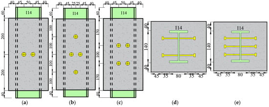
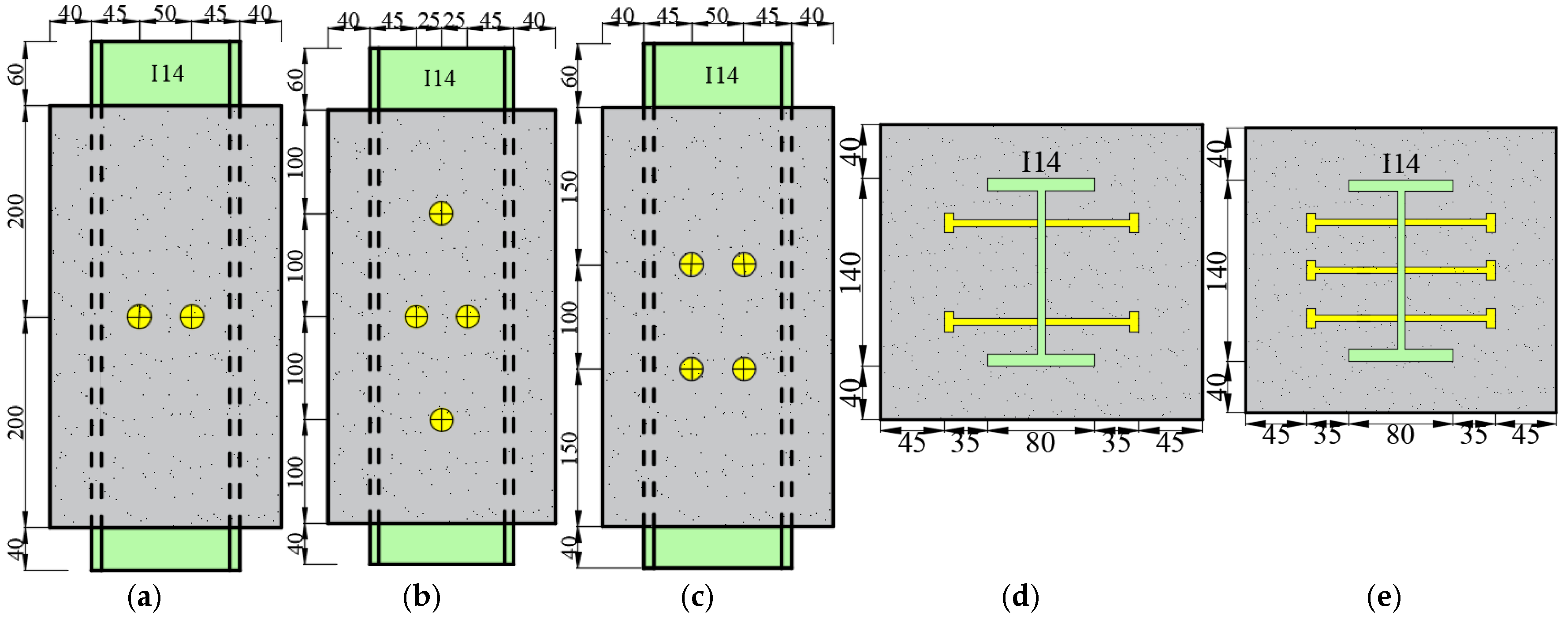
Considering the length, diameter, and arrangement of studs, five groups of push-out specimens of I-shaped steel-sprayed concrete short columns for tunnel support were designed: one group with the plum-shaped arrangement and four groups with the parallel arrangement. Three specimens were fabricated for each working condition. The section size of the specimen is 240 mm × 220 mm, the steel section is I14, the specification is 140 mm × 80 mm × 5.5 mm, the anchorage length is 400 mm, and the total height is 500 mm. The detailed design details of each specimen are shown in Table 1. According to the actual working conditions of tunnel support shown in Figure 2, the specimen does not consist of stirrups.
Table 1.
Specimen parameters.
Figure 2.
Configurations of test specimens (unit: mm). (a) Front view of single-row parallel arrangements. (b) Front view of plum-shaped arrangements. (c) Front view of double-row parallel arrangements. (d) Top view of parallel arrangements. (e) Top view of plum-shaped arrangements.
2.2. Material Properties
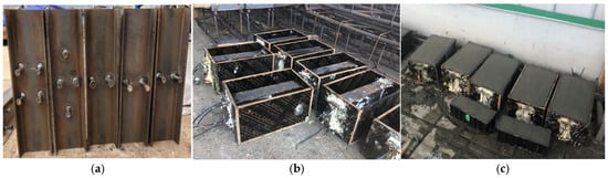
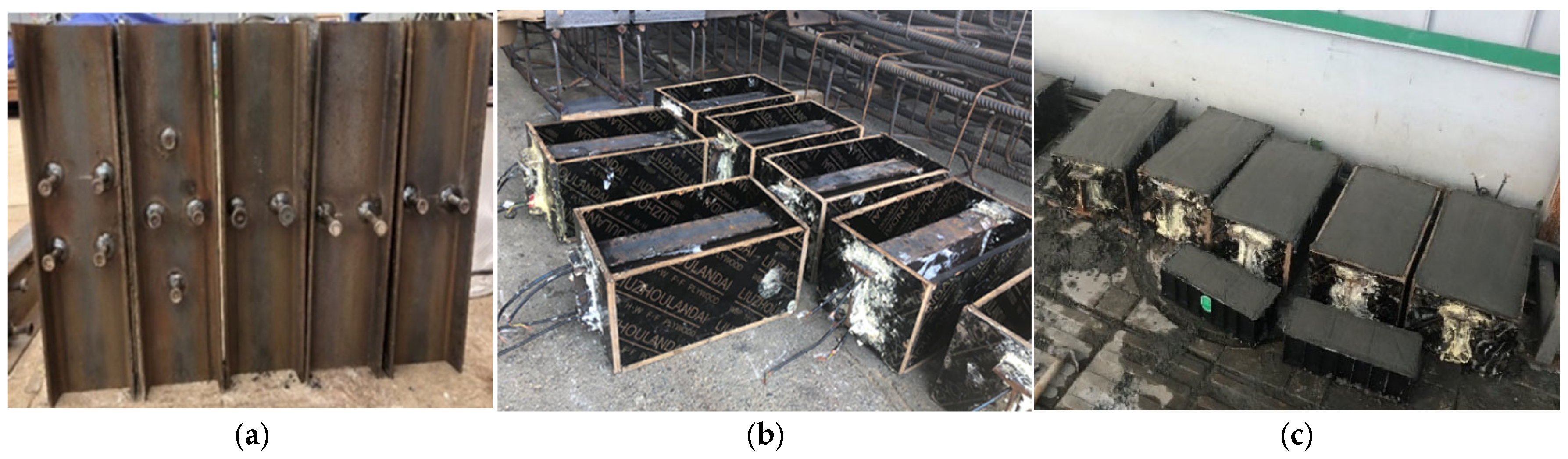
The production process of the specimen is shown in Figure 3. The steel is made according to the design parameters of the specimen. The stud shear connector is arranged in the design position of the steel web or flange by welding, and its material and welding process need to meet the corresponding standard. To prevent the external infiltration of concrete slurry, the grooves and gaps of the steel section are fully blocked by the foam sealant sealing material. During pouring, a vibrating rod is used for vibration, and the mold is knocked around to prevent air holes and bubbles. Finally, the surface is smoothed with a gray spoon. The specimens are cured in accordance with the specifications.
Figure 3.
Preparation of specimens. (a) Installation of studs. (b) Loading into mold. (c) Casting.
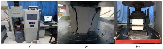
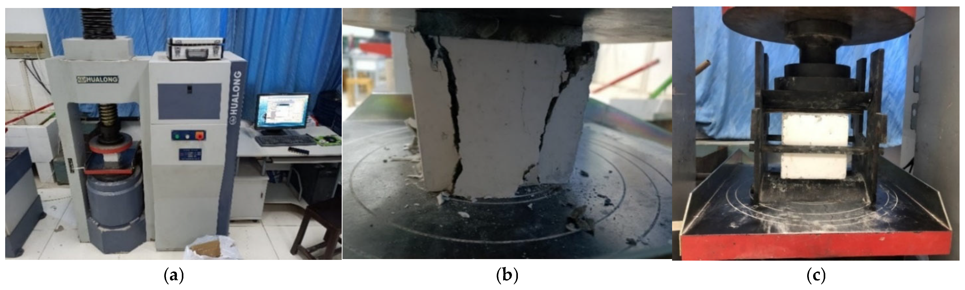
The mechanical property tests of shotcrete were carried out in accordance with Design of Concrete Structure (GB 50010-2010) [35]. For each batch, three 150 mm × 150 mm × 150 mm cubic specimens and three 150 mm × 150 mm × 300 mm prismatic specimens were prepared. Compressive strength and the elastic modulus were measured according to the standard requirements, and tensile strength was determined using the splitting method. The mechanical property test of shotcrete is shown in Figure 4.
Figure 4.
The mechanical property test of shotcrete. (a) Test machine. (b) Compressive strength test. (c) Splitting tensile strength test.
For the steel section, the web and flanges were first cut from the I-section and machined into standard steel coupons following Metallic Material-Tensile Testing at Ambient Temperature GB/T 228-2010 [36] and then subjected to tensile tests. The mechanical properties of the studs were determined following the procedures specified in GB/T 228-2010. The yield strength, ultimate tensile strength, and elastic modulus of the steel section and studs were provided by the manufacturer. The results are shown in Table 2 and Table 3.
Table 2.
Concrete material properties.
Table 3.
Yield stress, ultimate tensile resistance, and elastic modulus of steel and studs.
2.3. Test Setup and Instrumentation
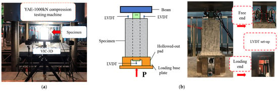
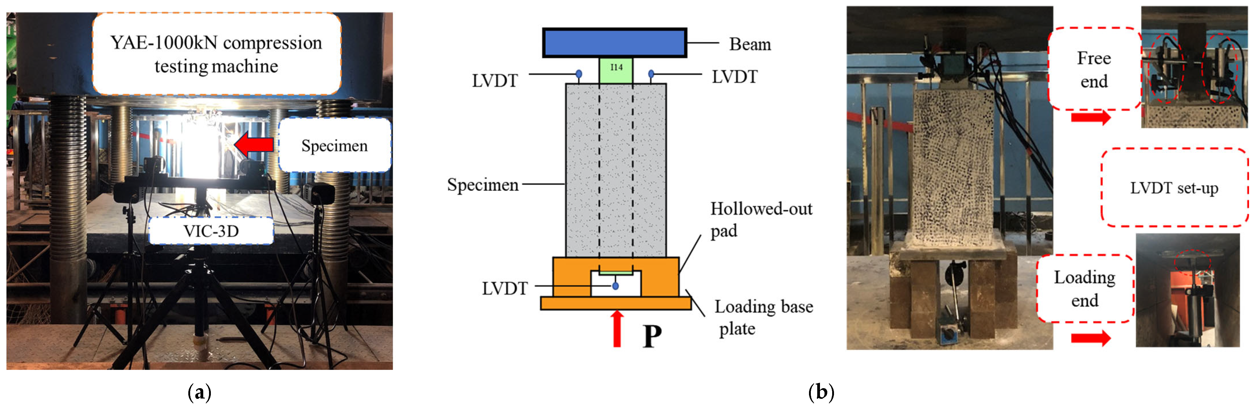
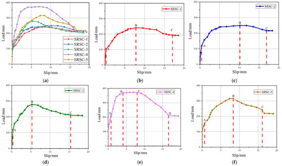
Figure 5 shows the design for the push-out test. The interfacial slip was quantified by means of linear variable differential transformers (LVDTs) positioned at the two ends of the specimen. In practice, the relative displacement between the loaded and unloaded ends was obtained from the difference in the corresponding LVDT readings, and this value was taken as the slip at the steel–shotcrete interface. The specific sensor arrangement is shown in Figure 5b.
Figure 5.
Experimental setup diagram. (a) Setup of push-out test. (b) Displacement measurement settings.
To gain deeper insight into the stress transfer and mechanical behavior of steel-reinforced shotcrete (SRSC) members under external loading, a visual image correlation–3D test system (VIC-3D) was employed in this study. This system enables the real-time monitoring of full-field deformation on the specimen surface, thereby accurately elucidating the mechanism by which the load is transferred from the shotcrete layer to the internal steel core.
During the experiments, the VIC-3D system utilized a high-speed camera operating at 500 frames per second to capture speckle images on the specimen surface. The acquired image sequence over the entire loading process was then processed to quantify the spatial distributions of the displacement and strain fields. This approach provides intuitive and reliable data for investigating complex mechanical phenomena such as crack propagation and stress concentration.
The external load is mainly transferred to the steel core via the shear resistance of the headed studs and the interfacial bond between the shotcrete layer and the steel element. To achieve full contact among the constituent parts, each specimen was subjected to a preliminary load corresponding to 5% of the predicted ultimate capacity before the formal test commenced. Thereafter, loading was imposed under displacement control at a constant rate of 0.5 mm/min. The test proceeded until the specimen’s slip resistance was fully degraded, and the load recorded at this point was defined as the ultimate slip-bearing capacity.
3. Experimental Results and Discussion
3.1. Load–Slip Curve
By introducing mathematical criteria for characteristic points, the boundaries between different stages of the bond–slip response are clearly defined as follows:
Initial slip point (Ss): This is defined as the point at which the load–slip curve starts to deviate from linear growth, i.e., the slip value corresponding to d2τ/dS2 = 0. For the specimens tested in this study, Ss = 0.08–0.12 mm.
Ultimate load point (Su): This is defined as the slip value corresponding to the maximum load Pu, determined by the first derivative condition dP/dS = 0.
Residual load point (Sr): This is defined as the slip value corresponding to a load equal to 0.85 Pu, by analogy with the definition of ductility in concrete structural design codes [36].
Drawing on the experimental observations and the delineated mechanical stages, the load–slip responses of both single-row and double-row parallel stud specimens can be partitioned into four characteristic phases:
(1) No-slip stage (0 ≤ S ≤ Ss, O-A): At this stage, the interfacial relative slip does not exceed Ss ≤ 0.1 mm, and the average bond stress τ increases linearly with slip, following τ = K·S, where K is the initial bond stiffness coefficient.
(2) Rising stage (Ss < S ≤ Su, A-B): The chemical bond gradually deteriorates, and the studs begin to provide the main shear resistance, so the curve exhibits a hyperbolic growth pattern. In the slip section, with the increase in load, the interface between steel and shotcrete begins to produce relative slip, and the studs have anti-slip properties.
(3) Descending stage (Sc < S ≤ Sr, B-C): Some studs yield, and/or shotcrete cracks, leading to a gradual reduction in load-carrying capacity. After the ultimate load is reached, the load–slip curve starts to descend. Pronounced relative sliding occurs between the steel section and shotcrete; the studs reach the yield strength and undergo ductile deformation, while cracks originating at the loading end propagate through the shotcrete along the specimen.
(4) Horizontal residual stage (S ≥ Sr): The residual bond resistance remains essentially stable, with p = pr. In this stable residual stage, the slip continues to increase, whereas the load remains approximately constant within a certain range (about 80%Pu) and no longer decreases significantly.
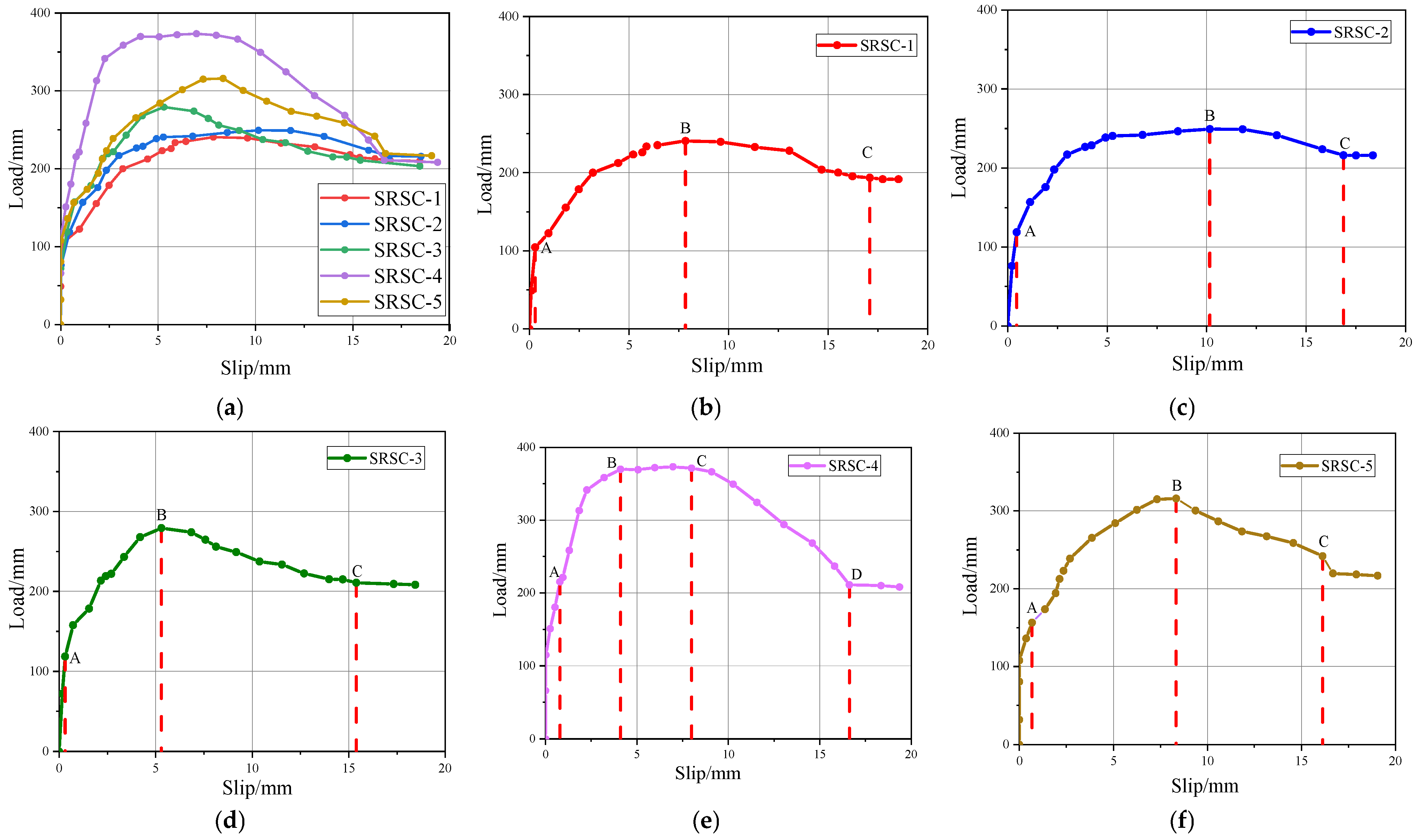
In contrast, for the specimens with staggered (plum blossom) stud arrangements, the load–slip curve includes an additional stage, as shown in Figure 6e.
Figure 6.
Load–slip curves of SRSC specimens. (a) Comparison chart. (b) SRSC-1. (c) SRSC-2. (d) SRSC-3. (e) SRSC-4. (f) SRSC-5.
(5) Load-stable stage (Su < S ≤ Sc, B-C): After the ultimate load is reached, the load remains approximately constant, with p = Pu, while the relative slip continues to increase. The load-stable section appears after the nonlinear load rising section; with the increase in load, the interfacial relative displacement follows a hyperbolic growth pattern with increasing load, until the attainment of the ultimate anti-sliding capacity. The limit slip resistance is then kept constant.
Unlike prior investigations, at the early stage of loading, a distinct turning point separates the non-slip stage from the slip stage; after debonding occurs at the interface, the slip response demonstrates ascending behavior rather than inclined progression. The smooth surface texture of shotcrete results in minimal chemical adhesion between I-steel and the concrete matrix; however, upper stud connectors enhance interfacial bonding, thereby influencing the load–slip mechanism. Additionally, the load–slip relationship lacks a residual plateau. The absence of transverse reinforcement in the tested I-shaped steel–concrete composites, combined with reduced cover thickness and insufficient lateral confinement, leads to specimen fracture and surface spalling, thus resulting in negligible residual horizontal capacity.
Table 4 summarizes the test results to evaluate the effectiveness of adding studs at the steel–concrete interface.
Table 4.
Experimental results in terms of ultimate load and residual load.
Comparing SRSC-1 (13 mm diameter) with SRSC-3 (16 mm diameter), under the same stud arrangement and quantity conditions, increasing the stud diameter from 13 mm to 16 mm results in a significant increase in ultimate load by 16.7% (from 240.5 kN to 280.7 kN), initial stiffness by 38.8% (from 42.3 kN/mm to 58.7 kN/mm), and ductility factor by 17.9% (from 2.8 to 3.3). This result demonstrates that enlarging the stud diameter can substantially improve the load-carrying capacity and stiffness of the composite system while simultaneously promoting more favorable ductile behavior.
Comparing SRSC-1 (50 mm length) with SRSC-2 (70 mm length), increasing the stud length from 50 mm to 70 mm only raises the ultimate load by 3.9% (from 240.5 kN to 249.9 kN) and initial stiffness by 7.8% (from 42.3 kN/mm to 45.6 kN/mm), while the residual strength ratio decreases by 5.7% (from 0.87 to 0.82). The results suggest that within the 50–70 mm range, stud length has a minor effect on the mechanical performance of the composite structure.
Under the same stud specification and quantity (both SRSC-4 and SRSC-5 use four rows of two studs of 13 × 50 mm), the quincunx stud arrangement increases the ultimate load by 16.8% (from 318.9 kN to 372.4 kN), initial stiffness by 21.0% (from 63.2 kN/mm to 76.5 kN/mm), and ductility factor by 18.4% (from 3.8 to 4.5) compared to the double-row parallel arrangement. This observation suggests that the quincunx configuration mobilizes the shear capacity of the studs more efficiently, thereby markedly improving the composite system’s mechanical behavior.
The load–slip curves of different stud configurations show obvious differences (Figure 6). The SRSC-4 specimen with a quincunx arrangement exhibits a distinct load stabilization stage after the ascending curve section, indicating more stable interface bond–slip performance, whereas specimens with parallel arrangements display the typical four-stage behavior: the non-slip, curve rising, curve descending, and horizontal residual slip stages. The ultimate load of SRSC-4 reaches 372.4 kN, which is 16.8% higher than that of the double-row parallel arrangement SRSC-5, thus confirming the advantage of the quincunx arrangement in improving interface bonding performance.
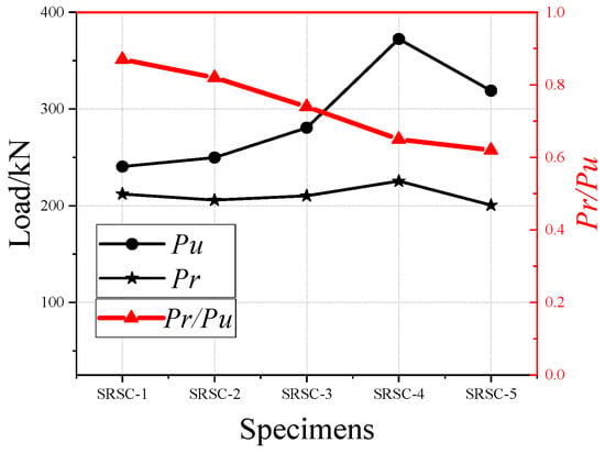
Figure 7 illustrates the bond capacity of specimens featuring diverse bolt configurations. The results reveal that the inclusion of studs significantly enhances the bond resistance at the steel–concrete interface of SRSC structures. Furthermore, studs are proven to be beneficial in improving the post-peak bonding characteristics, specifically regarding the residual load and slip. The residual loads of the SRSC1-5 series fall within the range of 172 to 225 kN, which demonstrates that studs can augment residual resistance by up to 80% of the ultimate load. This enhancement is attributed to the direct increase in interface shear stiffness provided by the stud’s locking mechanism. This study further identified that the geometric properties of the studs, including their height, diameter, and arrangement, exert a profound influence on the overall bond capacity. It was observed that as stud height and diameter increase, both the ultimate load (Pu) and residual load (Pr) exhibit a corresponding rise. In terms of anti-slip performance, specimens with a plum-shaped stud arrangement demonstrate the highest resistance, followed by those with a double-row configuration.
Figure 7.
Interfacial bond capacity of specimens.
3.2. Failure Process
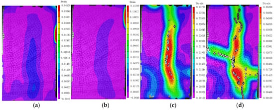
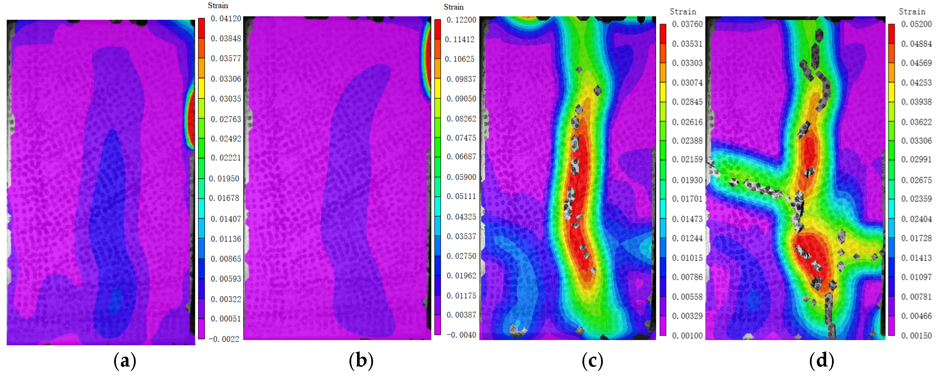
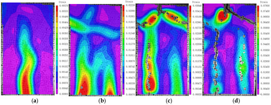
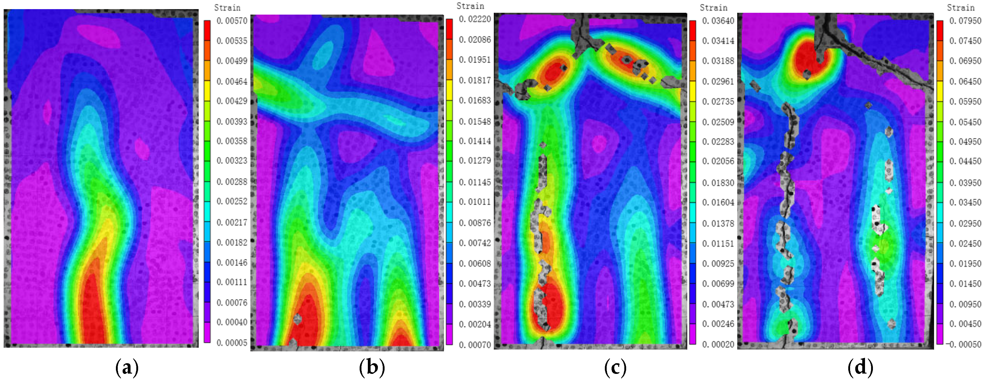
Both steel–concrete and plain concrete specimens demonstrated identical failure behaviors when subjected to stud constraints. Representative failure modes are illustrated in Figure 8.
Figure 8.
Evolution of maximum principal strain in SRSC-1. (a) P = 0.41 Pu. (b) P = 0.70 Pu. (c) P = P. (d) P = 0.88 Pu.
When the load is less than 0.48 Pu, there is no obvious crack on the surface of the SRSC-1 specimen, and the concrete is mainly compressed. When the load increases to 0.7 Pu, longitudinal cracks appear in the middle of the loading end. When the peak anti-sliding resistance (Pu) is attained, the crack propagates approximately along a 45° trajectory toward the boundary of the steel flange, and a new tensile crack is added at 1/4 of the transverse direction. When the load is reduced to 0.88 Pu, the concrete enters the tensile state, and the transverse tensile crack width expands significantly.
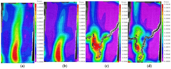
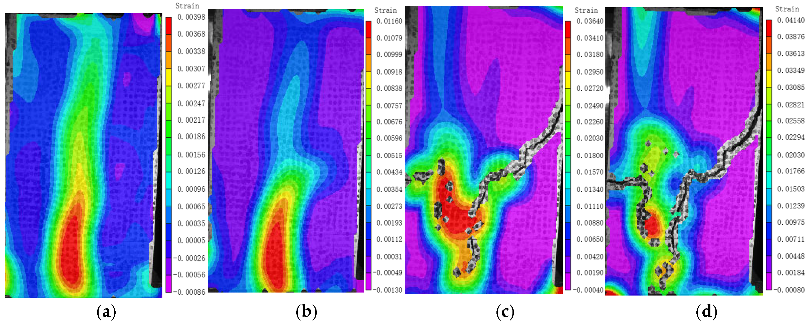
The surface strain evolution of the SRSC-2 specimen is shown in Figure 9. When the load is increased to 0.73 Pu, the crack quickly extends to the top. When the applied load attains the peak anti-sliding capacity (Pu), the concrete is predominantly subjected to tensile stresses. When the load is reduced to 0.85 Pu, the concrete is completely pulled. Due to the deformation of the stud, the width of the two longitudinal cracks increases sharply, and the specimen reaches the final failure.
Figure 9.
Evolution of maximum principal strain in SRSC-2. (a) P = 0.41 Pu. (b) P = 0.73 Pu. (c) P = Pu. (d) P = 0.85 Pu.
The failure process of specimen SRSC3 is shown in Figure 10. When the applied load remains below 0.43 Pu, an initial crack forms at the mid-span of the bottom surface near the loading end and then propagates in the longitudinal direction. When the load increases to 0.76 Pu, the shotcrete begins to be pulled, the interfacial chemical bonding force is completely destroyed, the longitudinal central crack develops to the left and right ends in the transverse middle, and two new expansion cracks are developed at 1/4 and 3/4 of the bottom end. When the load attains the ultimate anti-sliding capacity Pu, the cracks located at the left and right ends of the central transverse region coalesce. As the load subsequently decreases to 0.9 Pu, the longitudinal expansion crack on the shotcrete surface widens rapidly, and the specimen ultimately loses its anti-sliding resistance as a result of this expansion-induced failure.
Figure 10.
Evolution of maximum principal strain in SRSC-3. (a) P = 0.40 Pu. (b) P = 0.76 Pu. (c) P = Pu. (d) P = 0.86 Pu.
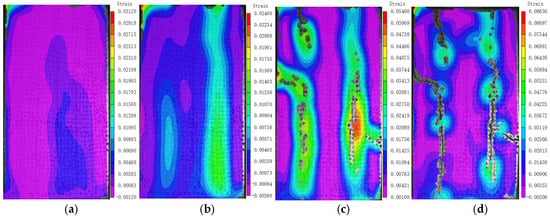
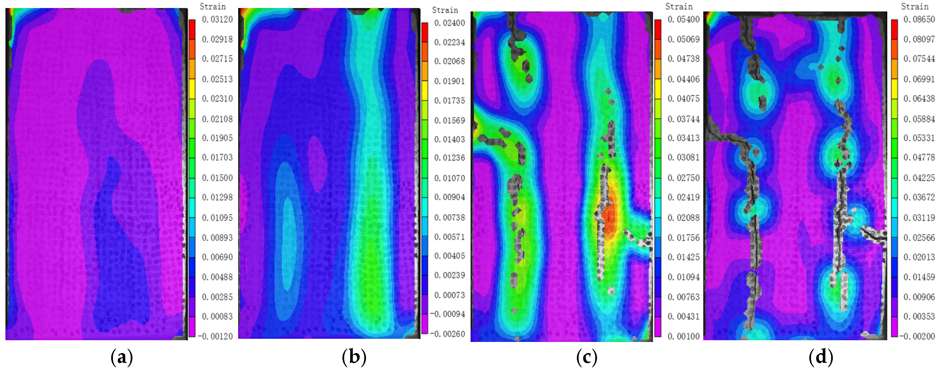
The surface strain evolution of the SRSC-4 specimen is shown in Figure 11. When the load is at 0.32 Pu, longitudinal cracks appear in the middle of the loading end. When the load increases to 0.8 Pu, cracks develop longitudinally at 1/4 and 3/4 of the bottom of the specimen, and transverse tensile cracks appear at 1/4 of the top. When the ultimate anti-sliding force Pu is reached, the crack in the middle of the top extends left and right along the longitudinal 45° and intersects with the transverse crack at the longitudinal 1/4. When the load is reduced to 0.85 Pu, the concrete is completely pulled, the longitudinal crack width increases sharply, the transverse crack changes little, and the specimen is destroyed.
Figure 11.
Evolution of maximum principal strain in SRSC-4. (a) P = 0.32 Pu. (b) P = 0.80 Pu. (c) P = Pu. (d) P = 0.85 Pu.
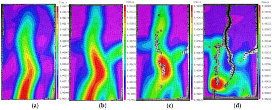
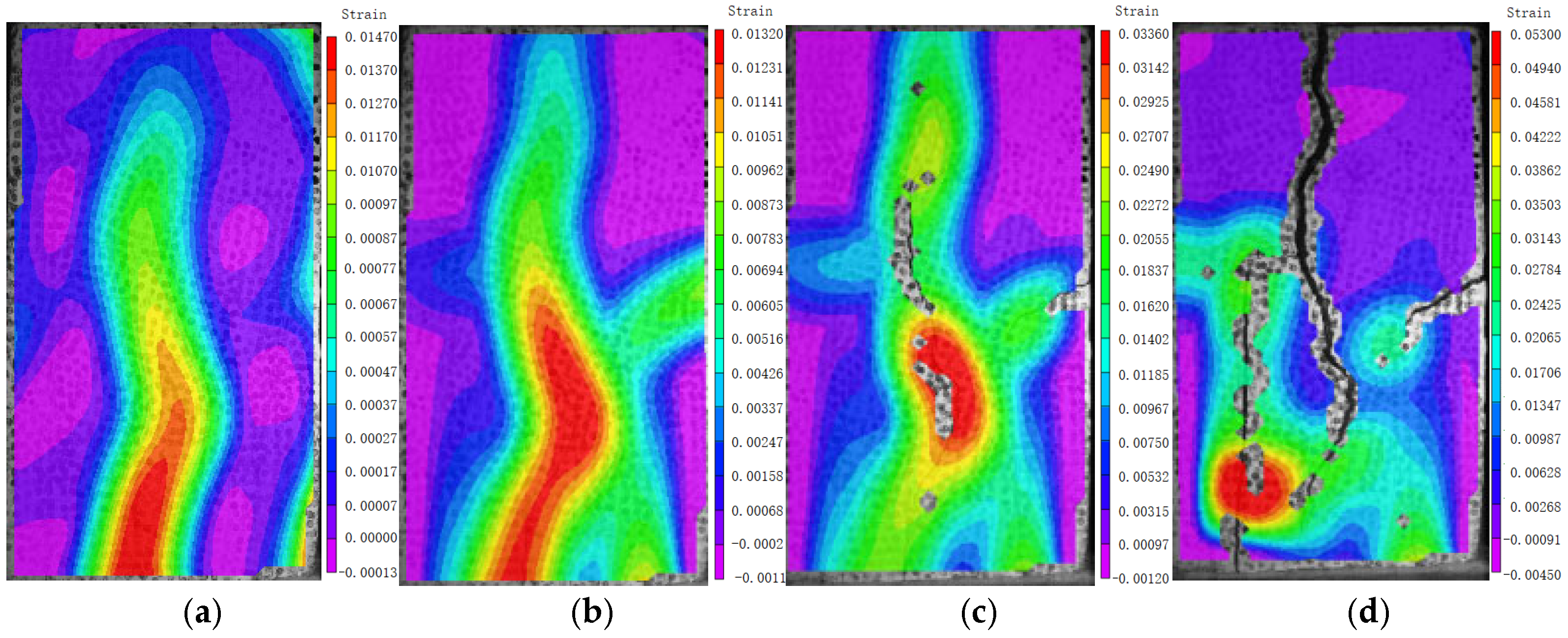
The progressive failure process of specimen SRSC5, as depicted in Figure 12, exhibits a series of well-defined stages as the applied load increases. At approximately 0.41 times the ultimate load-carrying capacity (Pu), an initial longitudinal crack initiates at the central region of the loading interface. As the load progresses to 0.77 Pu, two additional, distinct shear cracks emerge concurrently at the quarter and three-quarter points along the specimen’s height, rapidly propagating towards the top. Upon reaching the ultimate load Pu, the widths of these shear cracks significantly increase. Subsequently, at a load of 0.9 Pu, a catastrophic failure occurs as the longitudinal shear cracks penetrate the shotcrete surface, thus leading to the complete loss of the specimen’s shear resistance.
Figure 12.
Evolution of maximum principal strain in SRSC-5. (a) P = 0.41 Pu. (b) P = 0.77 Pu. (c) P = Pu. (d) P = 0.85 Pu.
3.3. Failure Modes
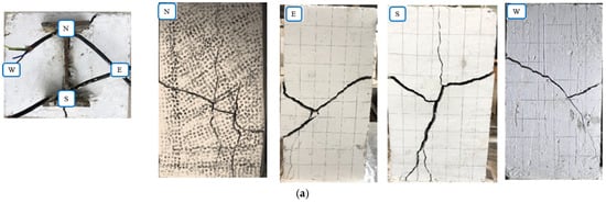
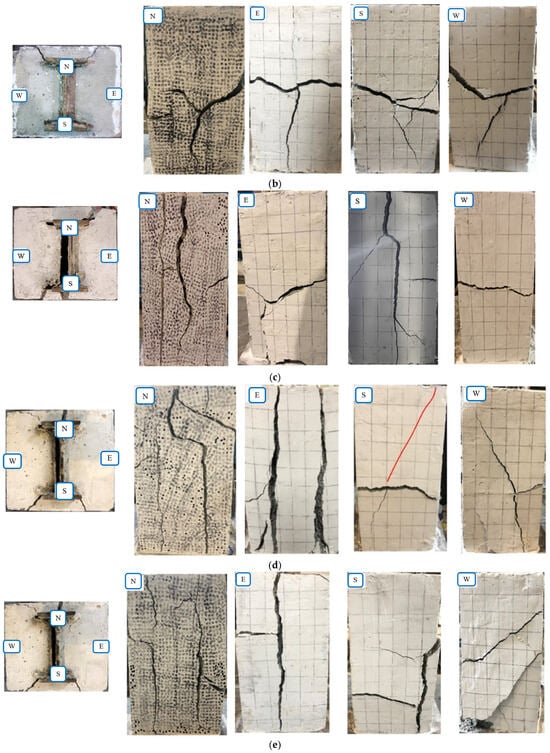
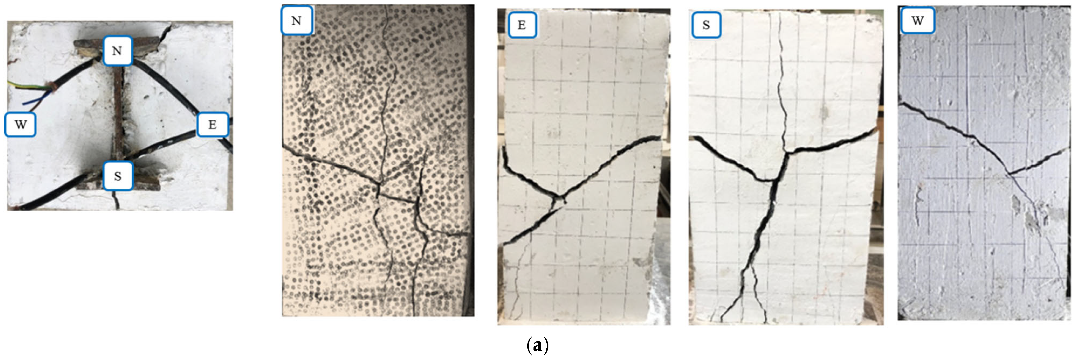
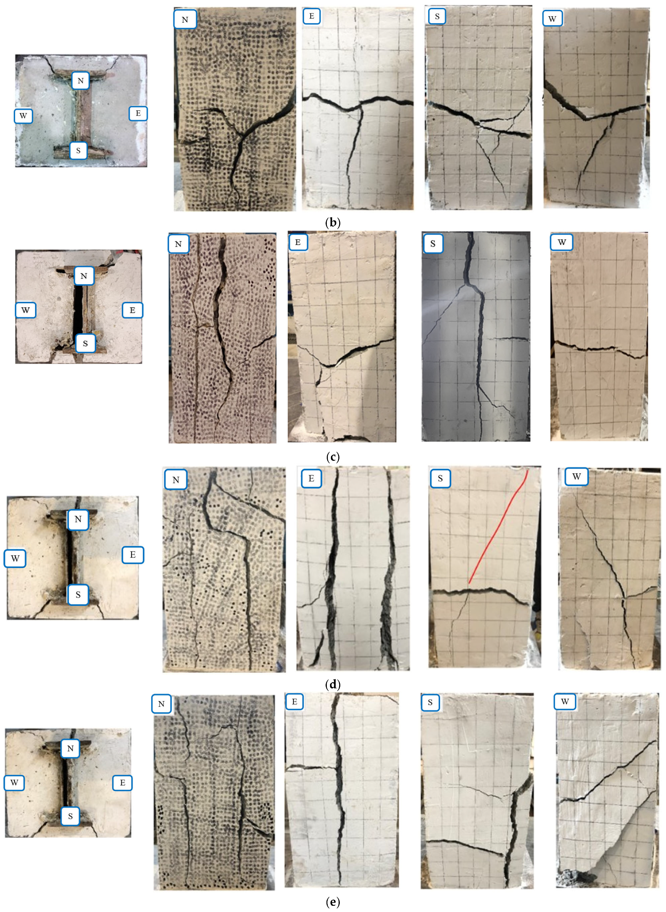
Figure 13a–e show the final failure modes of specimens SRSC-1 to SRSC-5 when reaching the ultimate bond–slip state, in which the shotcrete of each specimen exhibited characteristic cracking and failure, as detailed below:
Figure 13.
Failure modes of specimens. (a) Failure modes of SRSC1. (b) Failure modes of SRSC2. (c) Failure modes of SRSC3. (d) Failure modes of SRSC4. (e) Failure modes of SRSC5.
SRSC-1 experienced tensile splitting failure. Vertical shear cracks appeared at the positions corresponding to the steel flanges, and a 10–20° through transverse tensile crack formed in the mid-section of the specimen. The shear connectors on both sides of the steel web induced Y-shaped tensile cracks, which propagated transversely at 45°, while cracks perpendicular to the flange surfaces and 60° inclined cracks formed at the loading and free ends, respectively.
SRSC-2 also underwent tensile splitting failure. Tensile cracks at the transverse mid-section and vertical shear cracks perpendicular to the loading end in the lower-middle part sequentially formed and penetrated the shotcrete on the flange surfaces. Additionally, 20–45° through tensile cracks and 45° inclined vertical shear cracks were generated on both sides of the web. At both ends, cracks propagated at 45° along the flange tips or perpendicular to the flange surfaces.
SRSC-3 exhibited shotcrete splitting and expansion failure. Wide longitudinal splitting cracks formed on the flange surfaces, followed by a horizontal transverse through tensile crack in the mid-section. Transverse through-thickness tensile fractures were likewise identified on each side of the web. At both the loaded and free ends, these cracks were associated with shotcrete spalling propagating along the web direction.
SRSC-4 suffered from the longitudinal splitting and expansion failure of shotcrete. Two longitudinal splitting cracks and several transverse tensile cracks developed on the flange surfaces, with the entire surface showing an outward bulging tendency. Transverse through tensile cracks and 45° shear cracks propagating along the web surface formed on both sides of the web. At the loading end, cracks extended at 45° along the flange tips, parallel to the tips, and perpendicular to the flange surfaces; at the free end, cracks propagated at 45° along the flange tips and perpendicular to the back flange surface, with surrounding concrete tending to spall.
SRSC-5 also presented the longitudinal splitting and expansion failure of shotcrete. Through longitudinal splitting cracks formed on the flange surfaces, with a transverse tensile crack in the mid-section and an outward bulging trend on the entire surface. A through shear crack appeared at the left edge of the lower-middle part on the left web, while two 45° tensile cracks developed from bottom to top along the full cross-section on the right web. The left and right web surfaces showed distinct failure mode differences, possibly due to eccentric compression on the left side of the specimen. Cracks at both ends propagated at 45° along the flange tips and perpendicular to the flange surfaces, accompanied by concrete spalling, thus indicating final specimen failure.
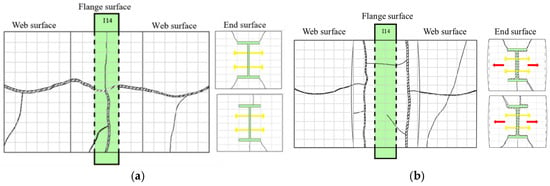
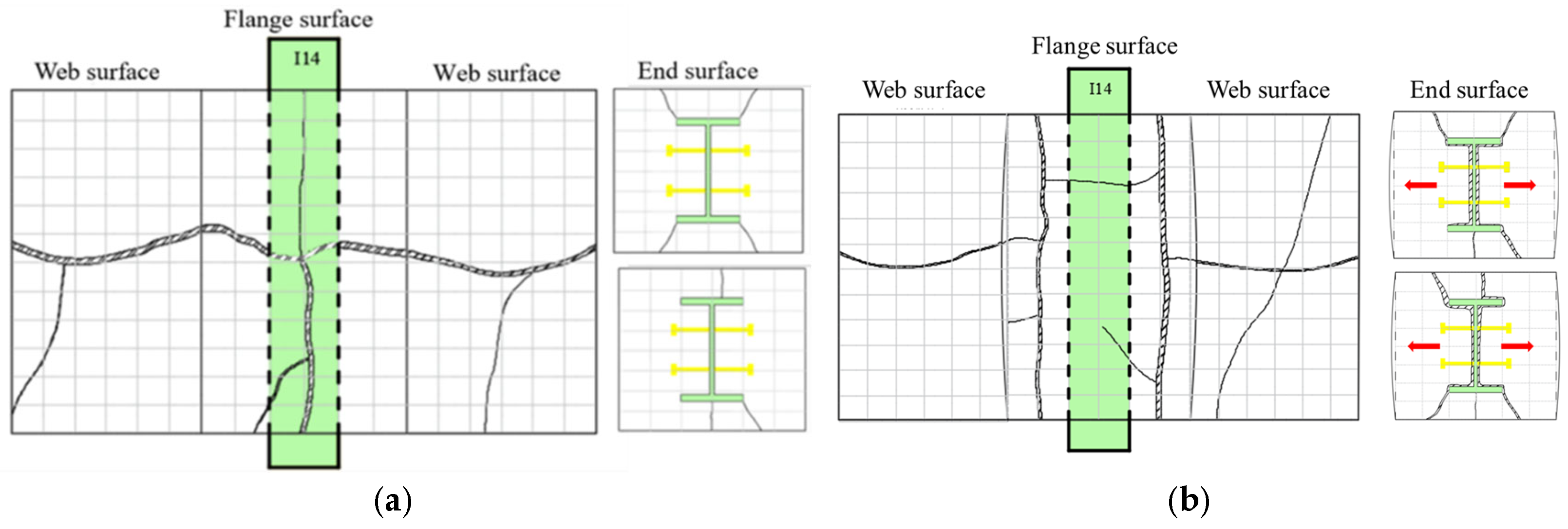
Figure 14 shows two typical failure modes of specimens: tensile failure and expansion failure. The difference is caused by the stud factor (quantity, arrangement). Specimens containing fewer shear studs (SRSC-1) or lower-capacity studs (SRSC-2) developed a failure mode characterized by tensile rupture. This was characterized by a longitudinal crack that traversed the sprayed concrete on both the front and back surfaces of the steel flange. Concurrently, tensile cracks of significant width developed along the transverse axis on the left and right faces of the web.
Figure 14.
Schematic pictures of concrete cracks. (a) Tensile failure. (b) Expansion failure.
As the stud strength is enhanced (SRSC-3), the layout is modified (SRSC-4), and the quantity is increased (SRSC-5). The dominant failure pattern of the specimen then transitions to an expansion-type failure. The shotcrete on the front and back of the steel flange forms two completely penetrating cracks along the longitudinal direction, and the width is large. At the same time, it bulges and peels along the direction of the web.
In this study, the distinction between tensile splitting and expansion failure is based on observed damage phenomena rather than a strict quantitative criterion. The two modes are identified mainly from crack orientation and distribution (such as vertical splitting along the flange, Y-shaped cracks around studs, and transverse through cracks), the location and extent of shotcrete spalling, and the post-peak load–slip response. Consequently, the classifications of “tensile splitting” and “expansion” failure adopted here should be understood as phenomenological descriptions of the observed global behavior, rather than mechanically rigorous failure criteria.
A comparative analysis of failure characteristics reveals significant differences between this study and the existing literature. The specimens investigated by Wang et al. exhibited a typical ductile failure mode, primarily attributed to the inclusion of stirrups (transverse reinforcement), which provided effective confinement. In contrast, the specimens in this study, which were characterized by a lack of transverse reinforcement, predominantly manifested brittle splitting or bursting failure. Similarly, the specimens reported by Ming et al. demonstrated progressive ductile failure, which can be credited to the superior crack control capabilities of High-Performance Fiber-Reinforced Concrete (HPFRC). Consequently, future research could explore the incorporation of fibers to mitigate the inherent brittleness of shotcrete or the addition of stirrups to enhance transverse confinement. Such modifications are expected to substantially optimize the interface bond performance and improve the overall load-bearing capacity of the support structure.
4. Analysis of Influencing Factors of Bond–Slip Between Steel and Shotcrete Interface
4.1. Finite Element Model and Validation
4.1.1. Modeling
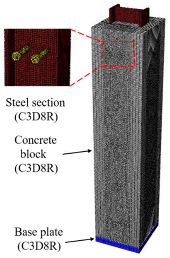
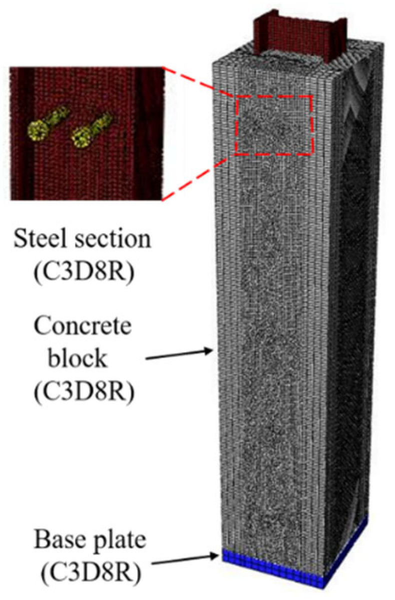
To conduct an in-depth and comprehensive investigation into the influencing factors of the bond–slip behavior at the steel section–shotcrete interface, complementary numerical analyses were carried out with the finite element package Abaqus. Figure 15 illustrates the element types and mesh configuration utilized in the finite element models. The contact interactions between the steel, studs, and shotcrete were defined through Boolean operations. A locally refined discretization with an element edge length of 5 mm was employed around the studs, whereas a coarser mesh with elements of 10–15 mm was assigned to zones remote from the studs. The mesh sensitivity study indicated that for element sizes below 8 mm, the change in the computed responses remained within 3%.
Figure 15.
Finite element representation of push-out experiment.
4.1.2. Material Constitutive Model and Properties
(1) Shotcrete: Shotcrete adopts the concrete plastic damage (CDP) model, which can reflect the development behavior of cracks, the change in damage degree, and the process of tensile softening. The change in failure surface is represented by the equivalent plastic strain of tension and compression and . The damage factor is introduced to express and simulate the stiffness attenuation process. The compression and tensile damage factor, elastic strain, inelastic strain, and cracking strain of shotcrete are calculated using Equations (1)–(3):
Here, dc and dt denote the compressive and tensile damage parameters of the shotcrete, while and represent its compressive and tensile stresses, respectively. According to the indoor experimental results of shotcrete in Section 2, the damage model parameters and damage factor value of shotcrete are obtained by combining the above formulas.
(2) Steel and stud: This steel and stud constitutive model simulation uses a double-oblique model.
The elastic modulus , yield stress , and corresponding yield strain were obtained from the material tests reported in Section 2. Both the steel members and reinforcing bars were modeled as exhibiting elastic–perfectly plastic behavior. The parameter settings of concrete damage plasticity model are shown in Table 5.
Table 5.
Parameter setting for concrete damaged plasticity model.
4.1.3. Bond–Slip Constitutive Relationship and Setting
The average bond stress–relative slip relationship between interfaces can be simulated by the cohesive behavior in the interaction property.
(1) Cohesive contact properties
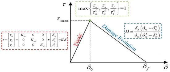
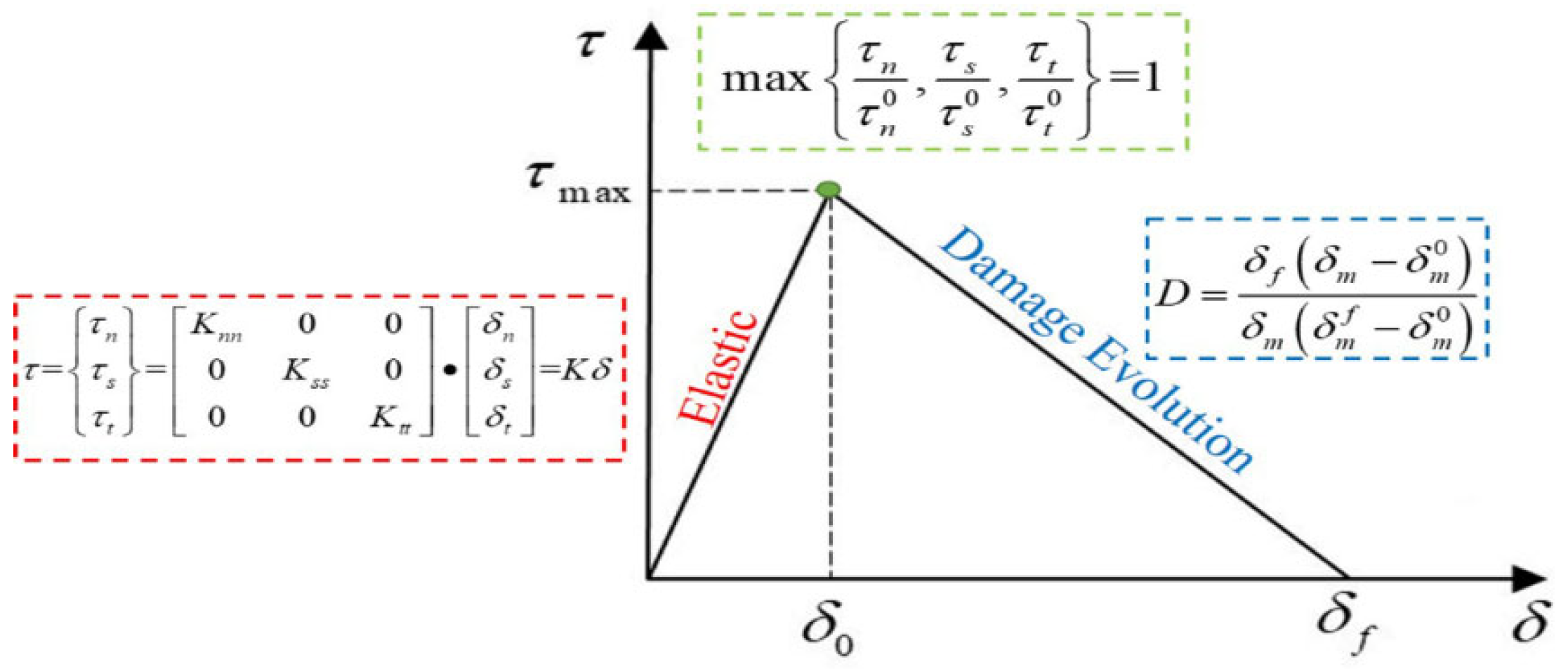
According to the results of the push-out experiment, the double-diagonal stress–separation displacement curve is consistent with the slip mode of the steel-sprayed interface, as shown in Figure 16. In the formula in this figure, , , and are interface normal bond stress and interface first and second tangential bond stress, respectively; , , and are the separation displacements corresponding to , , and , respectively; and K is the elastic bond stiffness in all directions. Additionally, is the displacement of the damage starting point, is the displacement when the damage is destroyed, and is the effective displacement in the loading process.
Figure 16.
Double-line stress–separation displacement curve.
(2) Parameters of constitutive relationship
The finite element simulations conducted in this study employ the double-diagonal model introduced in the preceding section as the bond–slip constitutive law. The determination of this model was mainly based on the following parameters: the slip stiffness coefficients; the normal, transverse, and tangential directions; the maximum bond force; the initial damage displacement value; and the total displacement value of complete failure. Assuming shotcrete is an isotropic material, the stiffness coefficients of the three directions are equal; that is, . The contact behavior parameters of adhesive force are as shown in Table 6. The cohesive parameters in Table are calibrated as follows: first, the initial parameter ranges are determined based on the recommended values in [23,27]; a trial-and-error approach is then used to optimize key parameters (such as the maximum bond strength and slip stiffness coefficient) so that the discrepancy between the simulated and experimental load–slip curves (especially for specimens SRSC1–SRSC3) in the ascending branch and at the peak load remains within 5%; and finally, the optimal parameter combination is obtained by comparing the simulation results under different parameter sets with the test data. Specifically, the slip stiffness coefficient K is back-calculated from the initial tangential stiffness of the interface; the maximum bond strength is taken as 28–32% of the splitting tensile strength of shotcrete; and the ratio of total displacement to initial damage displacement is determined from the slope of the descending branch of the experimental curves.
Table 6.
Contact behavior parameters of adhesive force.
4.1.4. Validation of FE Models
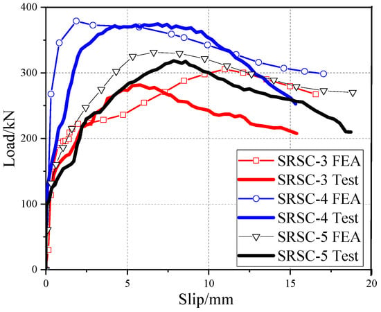
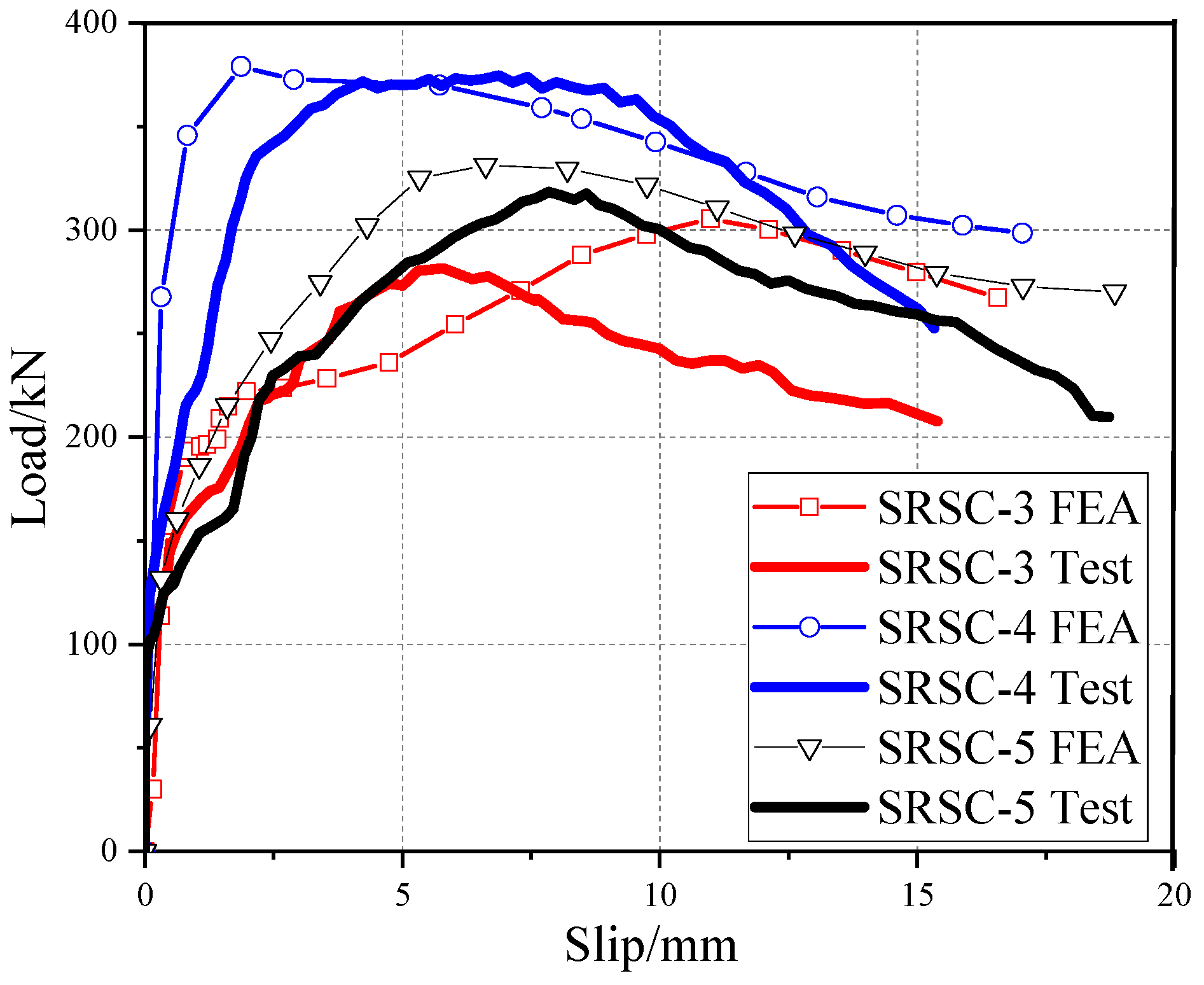
The experimental results of SRSC specimens are compared with the load–slip relationship of finite element analysis in Figure 17. The estimated results essentially agree with the experimental findings. Only the rising and residual parts of the curve exhibit some discrepancies in specimens with several row parallel stud arrangements. The established finite element model is reliable for studying the steel–concrete interface’s bond behavior and load transfer mechanism. The correlation analysis between finite element analysis results and test results is shown in Table 7.
Figure 17.
Comparison of finite element analysis predictions with experimental measurements.
Table 7.
Correlation analysis between FEA outcomes and experimental results.
4.2. Parametrical Study
The push-out test results show that the height, diameter, and arrangement of studs influence the bond behavior of SRSC. Therefore, this section uses the finite element model to analyze the above three factors. Because the variation in bond resistance along the longitudinal direction of the interface is neglected, the expression for the average bond stress is as given in Equation (4).
P is the external load applied to the specimen (kN); Cs denotes the perimeter of the steel cross-section, 590 mm; and La is the anchorage length of the steel within the shotcrete (mm), 400 mm.
4.2.1. Height of Stud
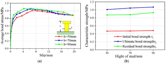
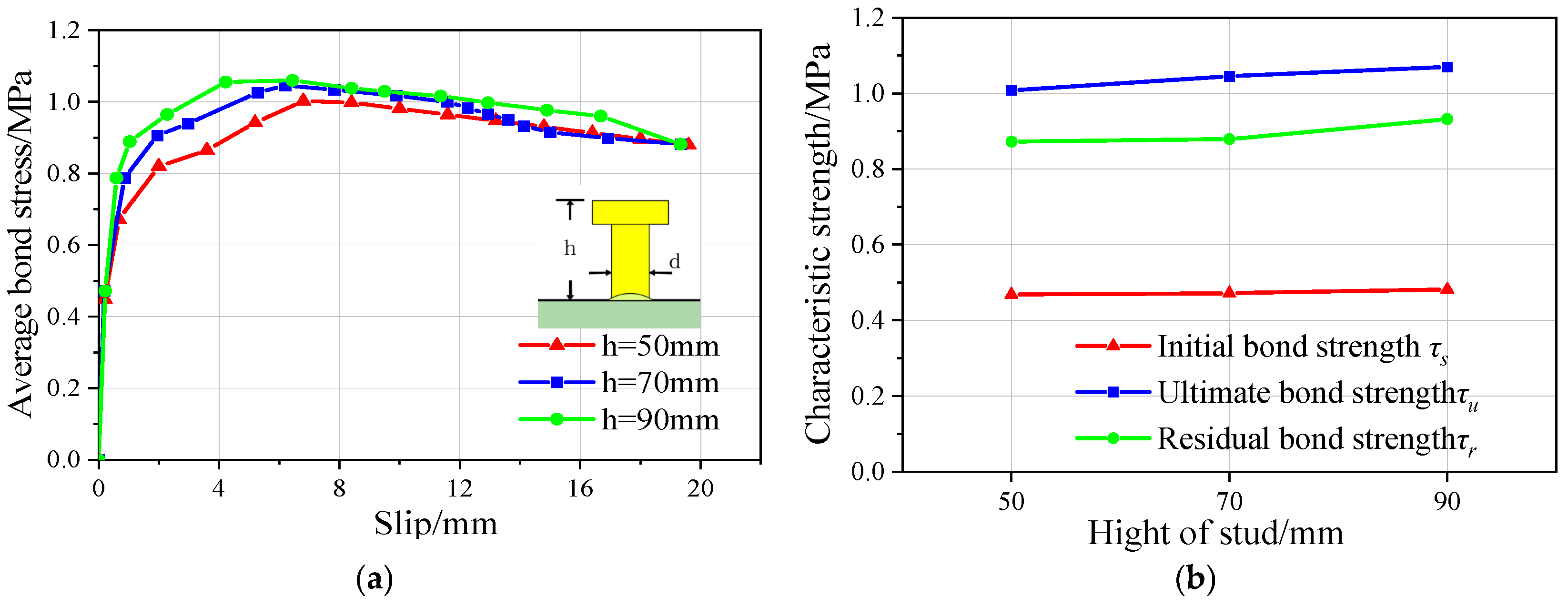
Figure 18 presents the average bond stress–slip and characteristic strength curves with different bolt heights. With the change in the height of the stud, the numerical variation curves of each characteristic strength point to the initial binding strength, ultimate bond strength, and residual bond strength, which are basically at the same level, and the corresponding relative slip of the interface is equal. This result is consistent with the experimental observations. Therefore, within the parameter range considered in this study, changing the stud height has only a minor effect on the shear–slip resistance of the steel–concrete composite interface.
Figure 18.
FEA results of specimens with different stud heights. (a) τ-S curves. (b) Characteristic curve.
4.2.2. Diameter of Stud
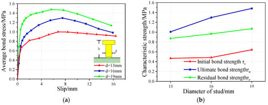
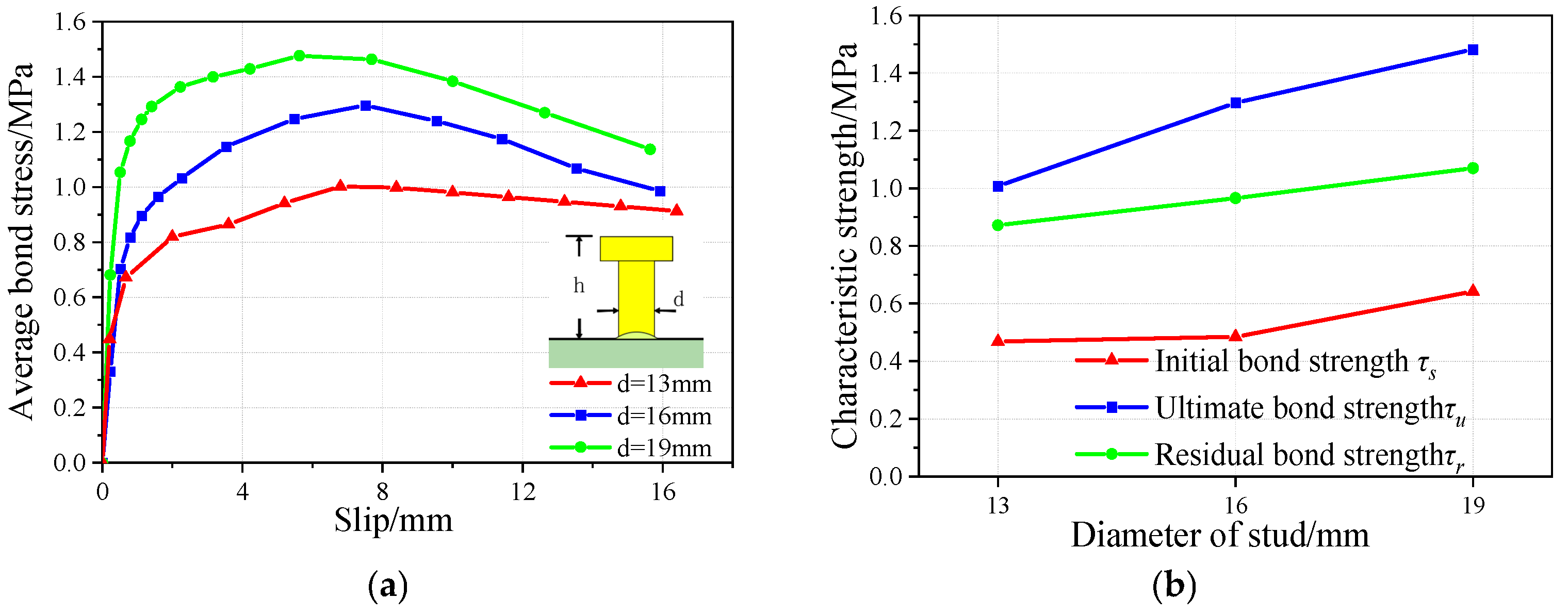
The influence of stud diameter on load–slip behavior and bond stress change is shown in Figure 19. The relationship between the average bond stress and slip for specimens incorporating studs of various diameters remains identical. However, the larger the diameter of the stud is, the greater the stiffness. In the case of varying stud diameters, the size of each characteristic strength value increases linearly with an increase in stud diameter. With an increase in bolt diameter, both rose by 3.5 and 24.4%, 22.3 and 12.5%, and 9.7 and 9.6%. As a result, bond ability increases as the stud diameter increases. Therefore, within the parameter range considered in this study, increasing the stud diameter can effectively enhance the interfacial bond capacity, and this is one of the most influential factors affecting the load-carrying capacity.
Figure 19.
FEA results of specimens with different stud diameters. (a) τ-S curves. (b) Characteristic curve.
4.2.3. Layout Form
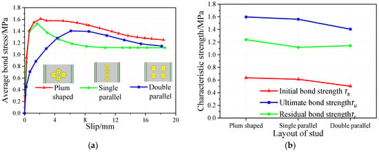
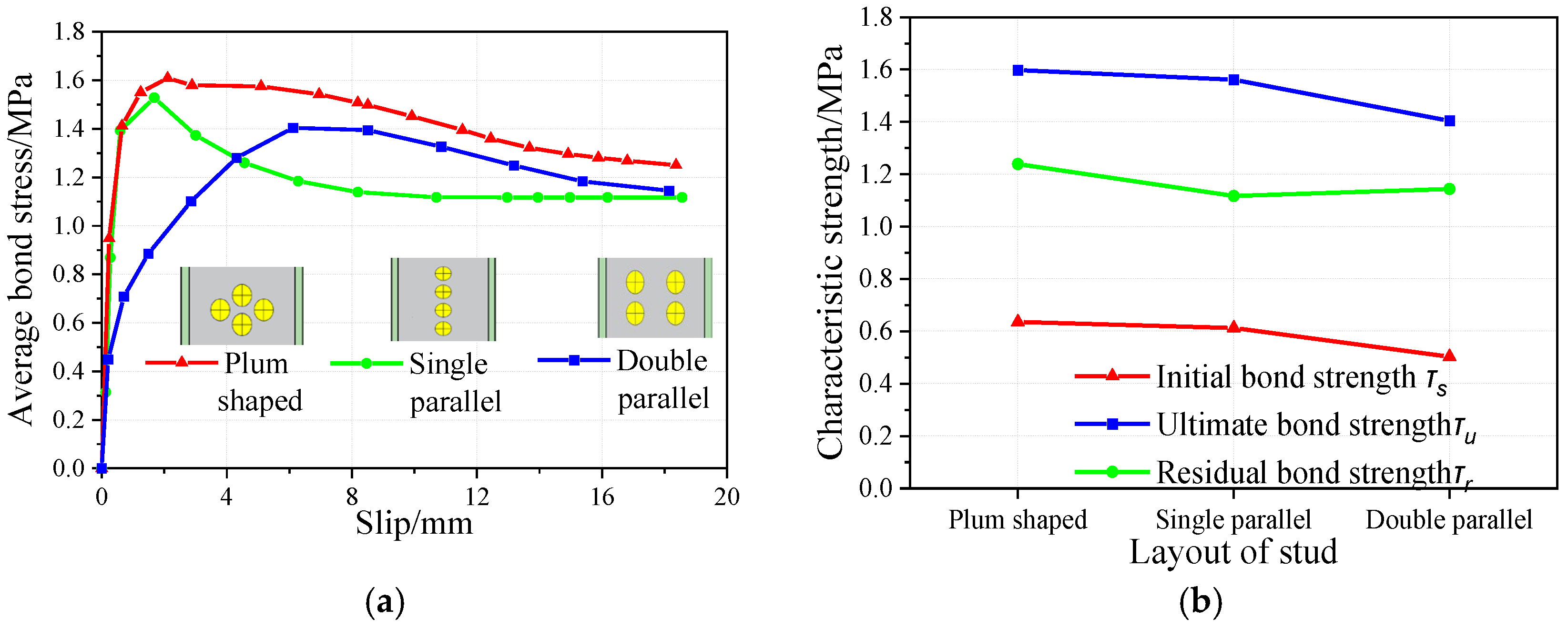
Figure 20 shows the numerical results of different arrangements of stud specimens. The curve of the plum-shaped and vertical parallel welded studs is steeper than that of the double-row parallel welded studs, thus indicating that the layout dramatically affects the interface bonding stiffness. Each characteristic strength value also varies when different arrangement types are used; the plum pattern arrangement has the largest value, and the double-row parallel arrangement has the smallest. The , and of the plum-shaped layout studs increase by 3.6% and 20.9%, 2.3% and 12.1%, and 9.8% and 7.7% compared with the other two layouts, respectively. Therefore, when the specifications of the studs are consistent, modifying the spatial configuration of the studs markedly affects the interfacial slip resistance of the SRSC, with the plum-shaped layout providing the most favorable performance. Therefore, within the parameter range considered in this study, changing the stud arrangement has a significant influence on the bonding performance of the SRSC interface, and it is shown that the staggered (staggered/two-row) arrangement performs the best and is one of the most influential factors affecting the load-carrying capacity.
Figure 20.
FEA results of specimens with different stud layouts. (a) τ-S curves. (b) Characteristic curve.
5. Bond–Slip Constitutive Relationship
5.1. Establishment of Constitutive Model
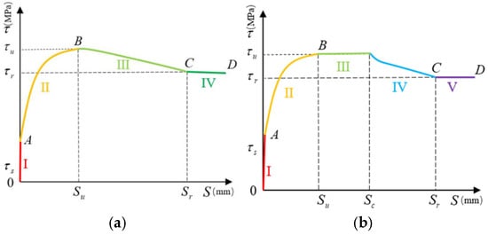
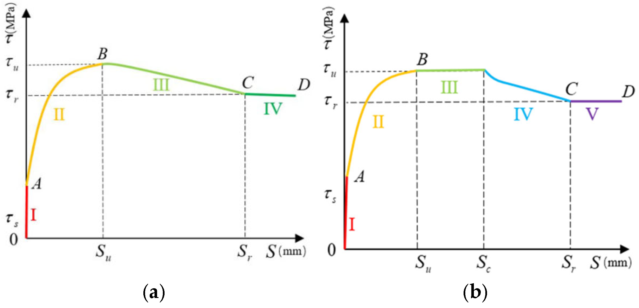
Based on the measured interface bond–slip responses and the analysis presented in Section 4, a mathematical representation of the τ–S relationship for specimens with natural bonding and those reinforced with welded studs is developed, as illustrated in Figure 21. In this τ–S curve, the characteristic points A, B, and C correspond to the initial bond strength τs, the peak bond strength τu, and the residual bond strength τr, respectively. Ps indicates the load for which the interface has just experienced slip, Pu the load that reaches the ultimate anti-sliding force, and Pr the final stable load. The corresponding relative slips are Ss, Su, and Sr, and Sc is the final slip amount corresponding to τu. The interfacial bond stiffness coefficient K represents the slope when the τ-S curve is linearly correlated.
Figure 21.
τ-S mathematic model. (a) Parallel layout. (b) Plum-shaped layout.
(1) Linear ascending segment:
(2) Curve rising segment: In this phase, the τ–S response exhibits a distinctly convex profile, with the tangent stiffness progressively diminishing and the curve gradually approaching a plateau.
The coefficient m in Equation (11) is obtained by performing a regression fit to the experimental data. By inserting the characteristic points A () and B (), which lie on the increasing portion of the curve, into the proposed expression, the following formulations for the parameters n and t are derived:
(3) Load-invariant section: For the specimen with a stud plum blossom arrangement, when the ultimate anti-sliding force is reached, the load remains unchanged, and the sliding increases:
(4) Descending stage: Once the peak load is attained, the specimen’s resistance to slip diminishes, while the relative displacement along the interface continues to grow. The gradient of the τ–S curve in this phase remains almost constant, resembling a mildly inclined straight line yet with a noticeable convex tendency. Accordingly, it is represented using a quadratic function of the following form:
By inserting the characteristic points B () and C () into Equation (10), which lie on the descending segment of the τ–S response curve, the coefficients α and β are yielded as follows:
(5) Horizontal residual stage: The interfacial shear resistance stabilizes at an approximately constant level, while the slip magnitude continues to grow.
In conclusion, the constitutive model describing the relationship between the average bond stress and slip for studs embedded in steel–shotcrete composite members can be formulated as follows:
5.2. Verification of Constitutive Relationship
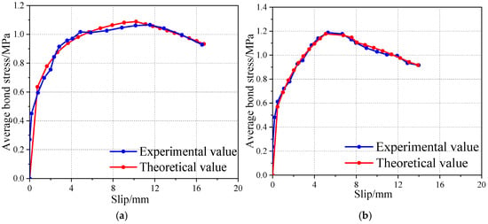
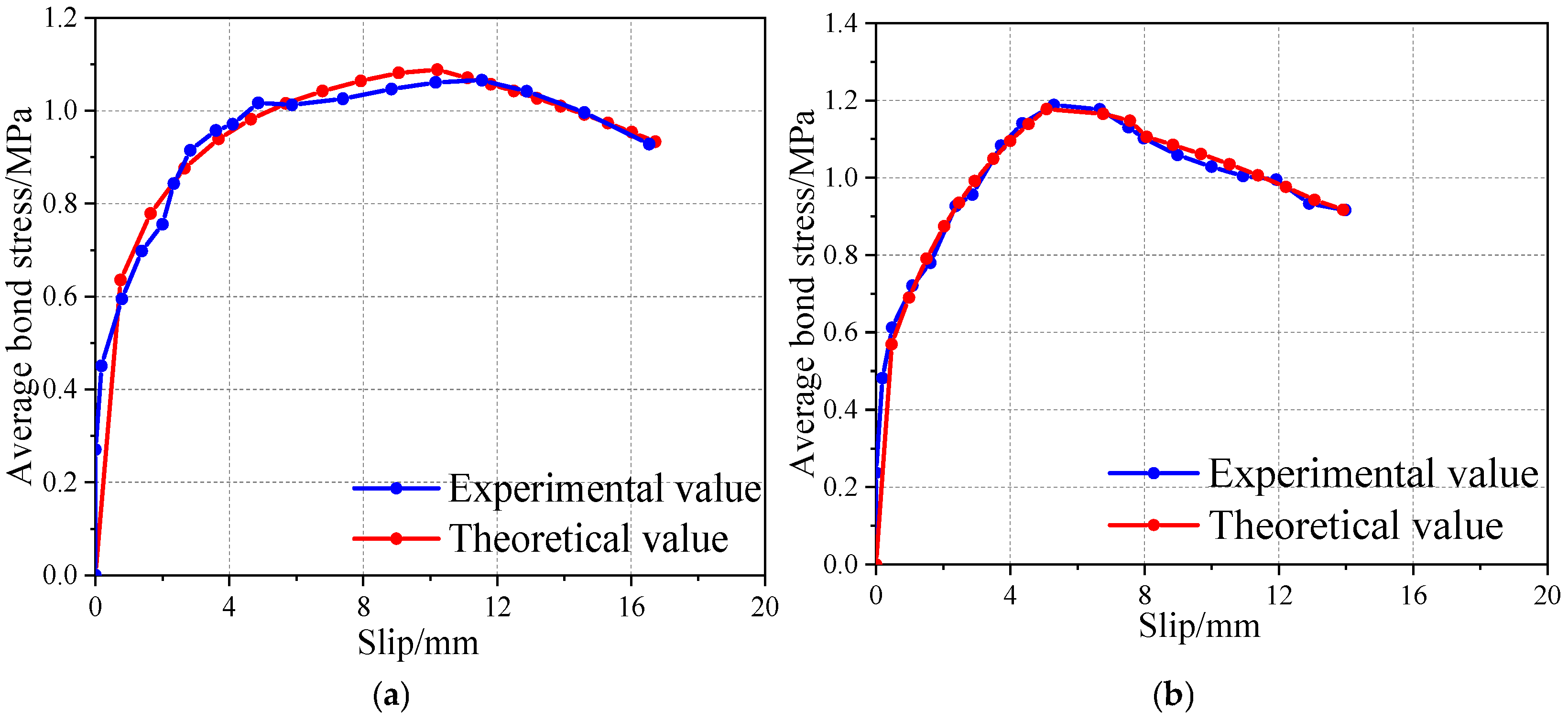
The comparison between the test curve and the constitutive model of SRC members with studs is shown in Figure 22. It is evident that the τ–S responses of specimens with parallel and plum blossom stud layouts closely match the corresponding stages of the model, thus indicating that the proposed constitutive formulation reliably captures the evolution of the average bond strength with relative slip for tunnel-supported I-shaped steel–shotcrete composite structures.
Figure 22.
Constitutive model and test curve comparison. (a) Parallel layout. (b) Plum-shaped layout.
In this study, the proposed bond–slip model was calibrated against the push-out responses of the SRSC specimens, and the measured load–slip curves were reproduced with good accuracy within the investigated range. Nevertheless, at this stage, the model should be regarded as primarily descriptive rather than fully predictive. The I-shaped steel–shotcrete stud-reinforced system considered here is a novel tunnel support configuration, and to the authors’ knowledge, no comparable test data are available for independent validation. Existing experimental studies on steel–concrete composites mainly concern cast-in-place members in buildings and bridges, with conventional reinforcement layouts and boundary conditions that differ fundamentally from those of tunnel shotcrete linings. Directly extrapolating the present model to such systems, or using models developed for cast-in-place composites to validate the steel–shotcrete–stud interface, would therefore be mechanically inconsistent and potentially misleading.
6. Conclusions
The bonding characteristics at the contact interface and the corresponding shear transfer mechanism were elucidated by means of push-out experiments combined with numerical analyses on SRSC specimens both incorporating studs and lacking studs. Based on these investigations, the following main conclusions are obtained:
- (1)
- Steel–shotcrete components featuring welded studs exhibit two primary failure mechanisms: splitting and expansion failures. Due to the absence of stirrups in the tested specimens, lateral confinement is insufficient, thus resulting in reduced shear resistance. Consequently, the studs undergo bending deformation without being severed upon failure.
- (2)
- The bond–slip relationship at the interface of steel-reinforced shotcrete structures incorporating studs comprises four distinct phases: an initial non-slip stage, a nonlinear ascending branch, a descending curve segment, and a horizontal residual portion. In specimens with plum-shaped stud configurations, a load stabilization phase emerges following the ascending curve segment.
- (3)
- The arrangement pattern and diameter of the studs have a significant impact on the ultimate load capacity: the specimen with a staggered arrangement (SRSC-4) reached an ultimate load of 372.4 kN, which is 16.8% and 54.9% higher than that of the specimens with a double-row parallel arrangement (SRSC-5, 318.9 kN) and single-row parallel arrangement (SRSC-1, 240.5 kN), respectively. The specimen with 16 mm diameter studs (SRSC-3) had an ultimate load of 280.7 kN, which corresponds to an increase of 16.7% compared to the 13 mm diameter specimen (SRSC-1, 240.5 kN), and its initial stiffness was significantly higher than that of the 13 mm diameter specimen.
- (4)
- Through experimental investigations, a bond–slip constitutive framework for steel–shotcrete specimens with stud connectors was developed, accompanied by analytical expressions for characteristic parameter determination. The validation outcomes demonstrate a very strong agreement between the proposed constitutive formulation and the corresponding experimental observations, with high accuracy in computational predictions, thereby offering a theoretical foundation for tunnel engineering applications.
- (5)
- Although this study reveals the bond–slip laws of the SRSC interface under specific test conditions, its universality remains to be expanded. Future research should focus on bridging the gap between laboratory results and practical engineering applications. To establish a more comprehensive and reliable design theoretical system, subsequent studies need to systematically investigate the coupling effects of multiple factors, such as size effect, concrete strength grade, and steel section surface condition. On this basis, advanced numerical simulation and artificial intelligence algorithms can be further integrated to develop an intelligent optimization method for stud arrangement, ultimately balancing the safety and economy of tunnel support structures and providing support for the refined design of engineering projects.
Author Contributions
Data curation, software, writing—original draft preparation, M.L. (Minhao Li); Validation, writing—review and editing, M.L. (Muyu Li); Conceptualization, funding acquisition, J.L. All authors have read and agreed to the published version of the manuscript.
Funding
This research was supported by the National Natural Science Foundation of China (Grant No. 51978088) and the State Key Laboratory of Geohazard Prevention and Geoenvironment Protection Independent Research Project (Grant No. SKLGP2021Z007).
Institutional Review Board Statement
Not applicable.
Informed Consent Statement
Not applicable.
Data Availability Statement
The original contributions presented in this study are included in this article. Further inquiries can be directed to the corresponding author.
Acknowledgments
The authors are grateful for the research support provided by the members of the State Key Laboratory of Geohazard Prevention and Geoenvironmental Protection.
Conflicts of Interest
The authors declare no conflicts of interest. The funder was not involved in the study design; the collection, analysis, or interpretation of data; the writing of this article; or the decision to submit it for publication.
References
- Elmy, M.H.; Nakamura, S. Static and seismic behaviors of innovative hybrid steel reinforced concrete bridge. J. Constr. Steel Res. 2017, 138, 701–713. [Google Scholar] [CrossRef] [Scilit]
- Liu, D.; Zuo, J.; Wang, J.; Zhang, T.; Liu, H. Large deformation mechanism and concrete-filled steel tubular support control technology of soft rock roadway-A case study. Eng. Fail. Anal. 2020, 116, 104721. [Google Scholar] [CrossRef] [Scilit]
- Ding, F.; Liu, J.; Liu, X.; Yu, Z.; Li, Y. Experimental investigation on hysteretic behavior of simply supported steel-concrete composite beam. J. Constr. Steel Res. 2018, 144, 153–165. [Google Scholar] [CrossRef] [Scilit]
- Ghorbani, M.; Shahriar, K.; Sharifzadeh, M.; Masoudi, R. A critical review on the developments of rock support systems in high stress ground conditions. Int. J. Min. Sci. Technol. 2020, 30, 555–572. [Google Scholar] [CrossRef] [Scilit]
- Wang, Z.; Xie, Y.; Lai, J.; Xie, Y.; Su, X.; Shi, Y.; Guo, C. Designing an innovative support system in loess tunnel. Geomech. Eng. 2021, 24, 253–266. [Google Scholar] [CrossRef]
- Xu, C.; Wang, K.; Gu, X. Study on bond behaviour of stainless steel reinforced concrete. Structures 2022, 44, 1454–1465. [Google Scholar] [CrossRef] [Scilit]
- Chiorean, C.G.; Buru, S.M. Practical nonlinear inelastic analysis method of composite steel-concrete beams with partial composite action. Eng. Struct. 2017, 134, 74–106. [Google Scholar] [CrossRef] [Scilit]
- Cao, R.; Cao, P.; Lin, H. Support technology of deep roadway under high stress and its application. Int. J. Min. Sci. Technol. 2016, 26, 787–793. [Google Scholar] [CrossRef] [Scilit]
- Zhou, Y.; Feng, S.; Li, J. Study on the failure mechanism of rock mass around a mined-out area above a highway tunnel-Similarity model test and numerical analysis. Tunn. Undergr. Space Technol. 2021, 118, 104182. [Google Scholar] [CrossRef] [Scilit]
- Zheng, Y.; He, S.; Yu, Y.; Zheng, J.; Zhu, Y.; Liu, T. Characteristics, challenges and countermeasures of giant karst cave: A case study of Yujingshan tunnel in high-speed railway. Tunn. Undergr. Space Technol. 2021, 114, 103988. [Google Scholar] [CrossRef] [Scilit]
- Li, W.; Yang, N.; Mei, Y.; Zhang, Y.; Wang, L.; Ma, H. Experimental investigation of the compression- bending property of the casing joints in a concrete-filled steel tubular supporting arch for tunnel engineering. Tunn. Space Technol. 2020, 96, 103184. [Google Scholar] [CrossRef] [Scilit]
- Roeder, C.W. Bond stress of embedded steel shapes in concrete. In Composite and Mixed Construction, Proc. of the US/Japan Joint Seminar; ASCE: New York, NY, USA, 1985; pp. 227–240. [Google Scholar]
- Roeder, C.W.; Chmielowski, R. Shear connector requirements for embedded steel sections. J. Struct. Eng. 1999, 125, 142–151. [Google Scholar] [CrossRef] [Scilit]
- Chen, L.; Dai, J.; Jin, Q.; Chen, L.; Liu, X. Refining bond-slip constitutive relationship between checkered steel tube and concrete. Constr. Build. Mater. 2015, 79, 153–164. [Google Scholar] [CrossRef] [Scilit]
- Wang, X.; Liu, Y.; Yang, F.; Lu, Y.; Li, X. Effect of concrete cover on the bond-slip behavior between steel section and concrete in SRC structures. Constr. Build. Mater. 2019, 229, 116855. [Google Scholar] [CrossRef] [Scilit]
- Zhang, L.; Wang, K.; Ling, Z.; Omar, A.; Guo, K. Bond-slip behavior between reactive powder concrete and H-shaped steel. J. Constr. Steel Res. 2023, 210, 108058. [Google Scholar] [CrossRef] [Scilit]
- Chen, L.; Wang, S.; Yin, C.; Li, S. Experimental study on the constitutive relationship between checkered steel and concrete. Constr. Build. Mater. 2019, 210, 483–498. [Google Scholar] [CrossRef] [Scilit]
- Ming, M.; Zheng, S.; Zhang, Y.; Zheng, Y.; Yang, S.; Song, M. Experimental study on the bond-slip behavior and stress transfer mechanism between shaped steel and high-performance fiber-reinforced concrete. Structures 2021, 34, 5013–5028. [Google Scholar] [CrossRef] [Scilit]
- Xu, F.; Song, S.; Lai, Z.; Chen, J. Mechanism of load introduction and transfer within steel-encased CFST members with shear connections. Eng. Struct. 2021, 242, 112576. [Google Scholar] [CrossRef] [Scilit]
- De Nardin, S.; El Debs, A.L.H.C. Shear transfer mechanism in connections involving concrete filled steel columns under shear forces. Steel Compos. Struct. 2018, 28, 449–460. [Google Scholar] [CrossRef]
- Song, J.; Wang, W.; Su, S.; Ding, X.; Luo, Q.; Quan, C. Experimental study on the bond-slip performance between concrete and a corrugated steel plate with studs. Eng. Struct. 2020, 224, 111195. [Google Scholar] [CrossRef] [Scilit]
- Song, J.; Wang, W.; Su, S.; Li, Y.; Lu, Z. Experimental investigation of the bond-slip behaviour between corrugated steel plates and concrete in CSRC structures. Constr. Build. Mater. 2021, 299, 124315. [Google Scholar] [CrossRef] [Scilit]
- Dong, H.; Zhao, Y.; Cao, W.; Chen, X.; Zhang, J. Interfacial bond-slip behaviour between reinforced high-strength concrete and built-in steel plate with studs. Eng. Struct. 2021, 226, 111317. [Google Scholar] [CrossRef] [Scilit]
- Huang, Y.; Chen, S.; Gu, P. Static and fatigue behavior of shear stud connection embedded in UHPC. Structures 2021, 34, 2777–2788. [Google Scholar] [CrossRef] [Scilit]
- Fang, Z.; Fang, H.; Huang, J.; Jiang, H.; Chen, G. Static behavior of grouped stud shear connectors in steel–precast UHPC composite structures containing thin full-depth slabs. Eng. Struct. 2022, 252, 113484. [Google Scholar] [CrossRef] [Scilit]
- Yang, H.; Zheng, Y.; Mo, S.; Lin, P. Push-out tests on studs with UHPC cover embedded in UHPC-NSC composite slab. Constr. Build. Mater. 2022, 331, 113484. [Google Scholar] [CrossRef] [Scilit]
- Wang, X.; Liu, Y.; Li, Y.; Lu, Y.; Li, X. Bond behavior and shear transfer of steel section-concrete interface with studs: Testing and modeling. Constr. Build. Mater. 2020, 264, 120251. [Google Scholar] [CrossRef] [Scilit]
- Liao, J.; Zeng, J.; Zi, H.; Zeng, W.; Zheng, Y.; Zhuge, Y. Push-out behavior and shear capacity prediction of PBL connectors in hybrid double-skin tubular members (DSTMs). Structures 2025, 74, 108629. [Google Scholar] [CrossRef] [Scilit]
- Zeng, J.; Sun, H.; Liao, J.; Zeng, W.; Zhuge, Y. Push-out tests on perfobond connectors in hybrid FRP-concrete-steel double-skin tubular members (DSTMs). Eng. Struct. 2025, 345, 121374. [Google Scholar] [CrossRef] [Scilit]
- Meng, H.; Wang, W.; Xu, R. Analytical model for the Load-Slip behavior of headed stud shear connectors. Eng. Struct. 2022, 252, 113631. [Google Scholar] [CrossRef] [Scilit]
- Ming, M.; Zheng, S.; Zhang, S.; Xu, Y.; Song, M. Experimental study on the constitutive relationship between shaped steel and HPFRC. Structures 2022, 38, 76–93. [Google Scholar] [CrossRef] [Scilit]
- Liu, C.; Lv, Z.; Bai, G.; Yin, Y. Experiment study on bond slip behavior between section steel and RAC in SRRC structures. Constr. Build. Mater. 2018, 175, 104–114. [Google Scholar] [CrossRef] [Scilit]
- Ren, R.; Qi, L.; Xue, J.; Zhang, X. Cyclic bond property of steel reinforced recycled concrete (SRRC) composite structure. Constr. Build. Mater. 2020, 245, 118435. [Google Scholar] [CrossRef] [Scilit]
- Xu, T.; Wang, Y.; Liang, C. The interfacial bond-slip behavior of I-section steel and reactive powder concrete at high temperatures. Constr. Build. Mater. 2022, 314, 125656. [Google Scholar] [CrossRef] [Scilit]
- GB/T50010-2010; Code for Design of Concrete Structures. China Architecture and Building Press: Beijing, China, 2010. (In Chinese)
- GB/T228.1-2010; Metallic Materials-Tensile Testing at Ambient Temperature. Standards Press of China: Beijing, China, 2011. (In Chinese)

Disclaimer/Publisher’s Note: The statements, opinions and data contained in all publications are solely those of the individual author(s) and contributor(s) and not of MDPI and/or the editor(s). MDPI and/or the editor(s) disclaim responsibility for any injury to people or property resulting from any ideas, methods, instructions or products referred to in the content. |
© 2026 by the authors. Licensee MDPI, Basel, Switzerland. This article is an open access article distributed under the terms and conditions of the Creative Commons Attribution (CC BY) license.