


Abstract
The high performance of optical components is contingent upon the quality of their optical surfaces, thereby imposing elevated standards on the methodologies employed for their fabrication. This study involved experimental research on freeform optical surface elements of polymethyl methacrylate with nano-surface roughness. In this study, the effects of machining parameters of ultra-precision slow tool servo turning on the surface roughness of different types of areas of freeform optical surfaces in the finishing stage were analysed. Based on the analysis of ultra-precision turning test results for freeform optical surfaces, a novel evaluation method for surface quality is proposed to assess the overall uniformity of surface quality across the entire freeform optical surface. Building upon this proposed evaluation method for overall surface quality uniformity, the processing method of high-quality freeform optical surfaces is studied. The results show that in the finishing stage, the radial feed rate exerts the greatest influence on the surface roughness of the freeform optical surface, especially the surface roughness of the concave surface area. This will exacerbate the surface quality inhomogeneity of the freeform optical surface. Based on the analysis results, optimal machining parameters were selected for processing trials. Concurrently, additional machining tests were conducted to further validate the influence of radial feed rate. Ultimately, a nano-scale PMMA freeform optical surface with uniform overall surface quality was achieved. The variation in surface roughness in different regions of the optical freeform is regulated to stabilise within 2 nm on the surface of polymethyl methacrylate. The overall uniformity of surface quality across the entire freeform optical surface was maintained at a high level.
1. Introduction
The demand for high-performance, lightweight optical systems in fields such as augmented reality, imaging, and lighting continues to grow, driving the development of optical components within optical equipment towards smaller form factors, higher integration, enhanced optical performance, and greater cost-effectiveness [1,2,3,4]. Freeform optical elements, distinguished by their flexible surface geometries and non-rotationally symmetric properties, provide exceptional design freedom for the optimisation of optical systems [5,6,7,8]. Polymethyl methacrylate (PMMA) has emerged as a key polymeric material for optical elements due to its outstanding transparency, favourable strength-to-weight ratio, and high cost-effectiveness [9]. The high-quality machined surface finish of freeform optical surfaces is fundamental to ensuring the optical performance of optical subsystems. Consequently, exploring machining methods to enhance the surface finish of freeform optical surfaces holds significant practical value.
Ultra-precision machining is widely used in the manufacture of optical components due to its ability to achieve submicron-level form accuracy and nanoscale surface roughness of freeform optical surfaces [10,11,12]. To achieve high-quality optical component fabrication, scholars have conducted extensive research on the factors affecting the surface quality of freeform surfaces in ultra-precision turning [13,14,15,16]. The surface quality of optical freeform parts is more sensitive to the factors that affect the surface quality of ultra-precision turning. First, the process parameters for ultra-precision slow tool servo turning are the main factors affecting the surface quality of freeform optical surfaces [17].
Zhou et al. studied the effects of radial, axial, and tangential vibrations on surface roughness in ultra-precision machining. It is proved that radial vibration has a greater influence on the surface topography than axial vibration and tangential vibration [18]. Cao et al. established a surface topography model affected by the parameters of ultra-precision turning process. The spatial frequency domain analysis of the turned surface was performed to determine the quantitative influence of conditional parameters on surface roughness [19]. Surfaces produced by SPDT typically depend on machining parameters and material properties [20]. The ultra-precision turning process is precise and stable, yet vibration is also inevitable during the machining process [21]. Lee et al. developed a dynamic model to evaluate vibration caused by changes in micro-cutting forces by studying the changes in micro-cutting forces caused by changes in the crystal orientation of the workpiece material. This model can predict local changes in the surface roughness of crystalline materials [22]. Wang et al. identified that high-frequency tip vibration is the most important factor affecting the surface roughness of single-point diamond turning. A surface topography prediction model considering tip vibration was established [23].
Scholars have conducted extensive research on tool paths for ultra-precision turning of freeform optical surfaces to obtain high-quality freeform surfaces. Based on the multi-body dynamics analysis principle of ultra-precision machine tools, Cheng et al. proposed a new tool path generation method for ultra-precision machining of freeform surfaces [24]. He et al. developed the STPGM-NURBS toolpath planning method, which can generate more uniform helical toolpaths for non-rotationally symmetric freeform surfaces, maintaining the tool residual height on the freeform surface within a very small range [25]. Prasad et al. established a process chain of tool path generation, cutting behaviour analysis, surface optimisation, and system integration to achieve high-precision manufacturing of single crystal germanium freeform optical devices [26]. The influence of diamond tools on the machined surface in ultra-precision machining has also been gradually paid attention to [27]. Especially for ultra-precision slow tool servo turning, due to the long machining time, tool wear and the resulting cutting vibration are inevitable during the machining process [18]. Li et al. integrated workpiece dimensions with tool vibration and wear, elucidating the mechanisms by which tool wear and workpiece diameter affect surface quality in ultra-precision turning [28].
Research dedicated to enhancing the surface quality of freeform optical surfaces focuses on factors such as the influence of ultra-precision turning process parameters and vibration on surface topography, alongside more precise toolpath planning for ultra-precision machining. However, the complex surface characteristics and non-rotationally symmetric nature of freeform optical surfaces heighten their sensitivity to process parameters, necessitating consideration of additional influencing factors when improving surface quality. Moreover, precise toolpath planning for ultra-precision machining necessitates analysis of the surface characteristics to balance surface quality across different regions of the freeform surface. However, limitations arise when dealing with freeform surfaces that defy straightforward mathematical description. Consequently, conducting qualitative and quantitative analyses of freeform surface quality, alongside developing efficient, high-quality machining methods, holds significant practical importance.
Methods for characterising machined surface quality primarily concern surface roughness, encompassing two-dimensional parameters such as Ra (arithmetic mean height), Rz (maximum height), and Rt (maximum cross-sectional height), alongside three-dimensional metrics including Sa (arithmetic mean height), Sz (maximum height), Sq (root mean square height), Sal (minimum autocorrelation length), and Str (aspect ratio of surface features), etc. [29,30]. For optical components such as lenses and laser mirrors, even a few nanometer-scale defects on the machined surface can lead to reduced imaging quality or laser efficiency [31]. Consequently, there are limitations in evaluating surface quality of freeform optical surfaces with two-dimensional roughness. Three-dimensional surface roughness offers advantages in this regard. However, the measurement accuracy of freeform surface roughness relies on optical measurement equipment. Moreover, the field of view of optical measurement devices is typically small, making it difficult to achieve comprehensive surface measurement and evaluation of the entire freeform optical surface. To overcome these challenges, this study quantitatively analysed the surface quality of different regions on the freeform optical surfaces. The influence of ultra-precision turning process parameters on the surface quality of distinct types of regions within the freeform optical surface was investigated. A novel surface quality evaluation method is proposed to assess the uniformity of surface quality across the entire freeform optical surface. These findings provide theoretical support for developing machining methods to produce high-quality freeform optical surfaces.
2. Evaluation of Surface Quality
Optical components demand exceptionally high machining quality, requiring not only assured optical performance but also complete mechanical characteristics. The properties of freeform optical surfaces are particularly complex. Therefore, this study employs both the three-dimensional roughness parameters Sa and Sq to analyse the machined surface quality of freeform optical surfaces, thereby ensuring their stable performance. The calculation method is as follows.
where z(x, y) represents the height information of the freeform surface. L and M are the size of the measurement area.
3. Experimental Setup and Equipment
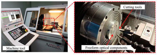
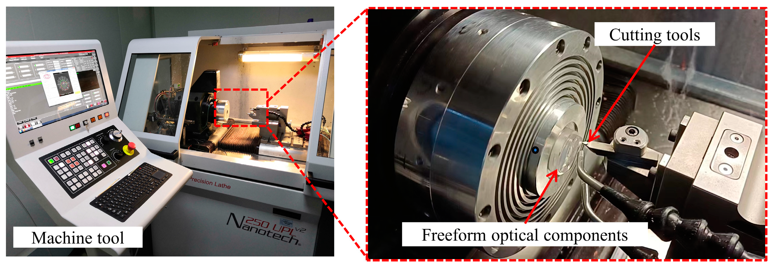
The machining equipment used in this study for the optical freeform ultra-precision machining test is the Moore Nanotech 250 UPLv2 ultra-precision machine tool (Moore Tools Inc., Bridgeport, CT, USA). As illustrated in Figure 1. The machine tool’s spindle (C-axis) is mounted on the X-axis feed. A vacuum chuck mounted on the spindle secured the workpiece, while the tool was positioned on the tool holder of the Z-axis feed. During machining, the servo motion axis (Z-axis) and the spindle’s rotational angle (C-axis) maintained strict synchronisation. The coordinated movement of the X, Z, and C-axes defined the machining trajectory, enabling low-frequency, large-stroke cutting operations.
Figure 1.
Ultra-Precision Machining test of freeform optical components.
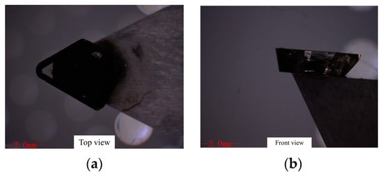
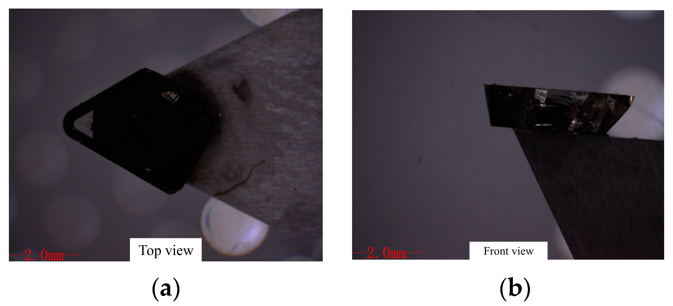
As illustrated by Figure 2, diamond cutting tools were employed in the machining experiments. In ultra-precision machining, the selection of tool parameters is of paramount importance. Due to the non-rotational nature of freeform surfaces and the complexity of their surfaces, it is necessary to analyse the freeform surface prior to machining to determine the range of tool parameters [32]. The tool arc radius of diamond cutting tools is 0.5 mm, with a rake angle of 45°. Owing to the extended duration of ultra-precision slow tool servo turning, prolonged continuous machining induces tool wear. Tool wear exerts a significant influence on both the ultra-precision turning process and the surface quality [20,27,28]. To mitigate the impact of tool wear on the surface quality of freeform surfaces during continuous machining, a new diamond tool was replaced every time when the machining test was completed.
Figure 2.
Diamond cutting tool: (a) Top view; (b) Front view.
4. Experiments and Discussion
The machining test was designed based on the Taguchi method to analyse the influence of ultra-precision turning parameters on the surface roughness of freeform surfaces. The controlling factors of the trial design include radial feed rate (μm/rev), angular increment (deg/ms), and depth of cut (μm). Based on prior research on freeform surface quality provides a reference for parameter selection [33,34]. Given the complexity of freeform surface curvature, the parameter range must encompass the critical zones affecting surface quality. Concurrently, the interval between parameter values must sufficiently reflect their impact on surface morphology and quality. The process parameters and their levels are shown in Table 1.
Table 1.
Processing parameters of ultra-precision machining.
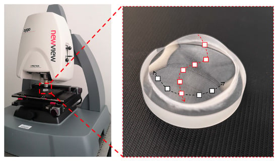
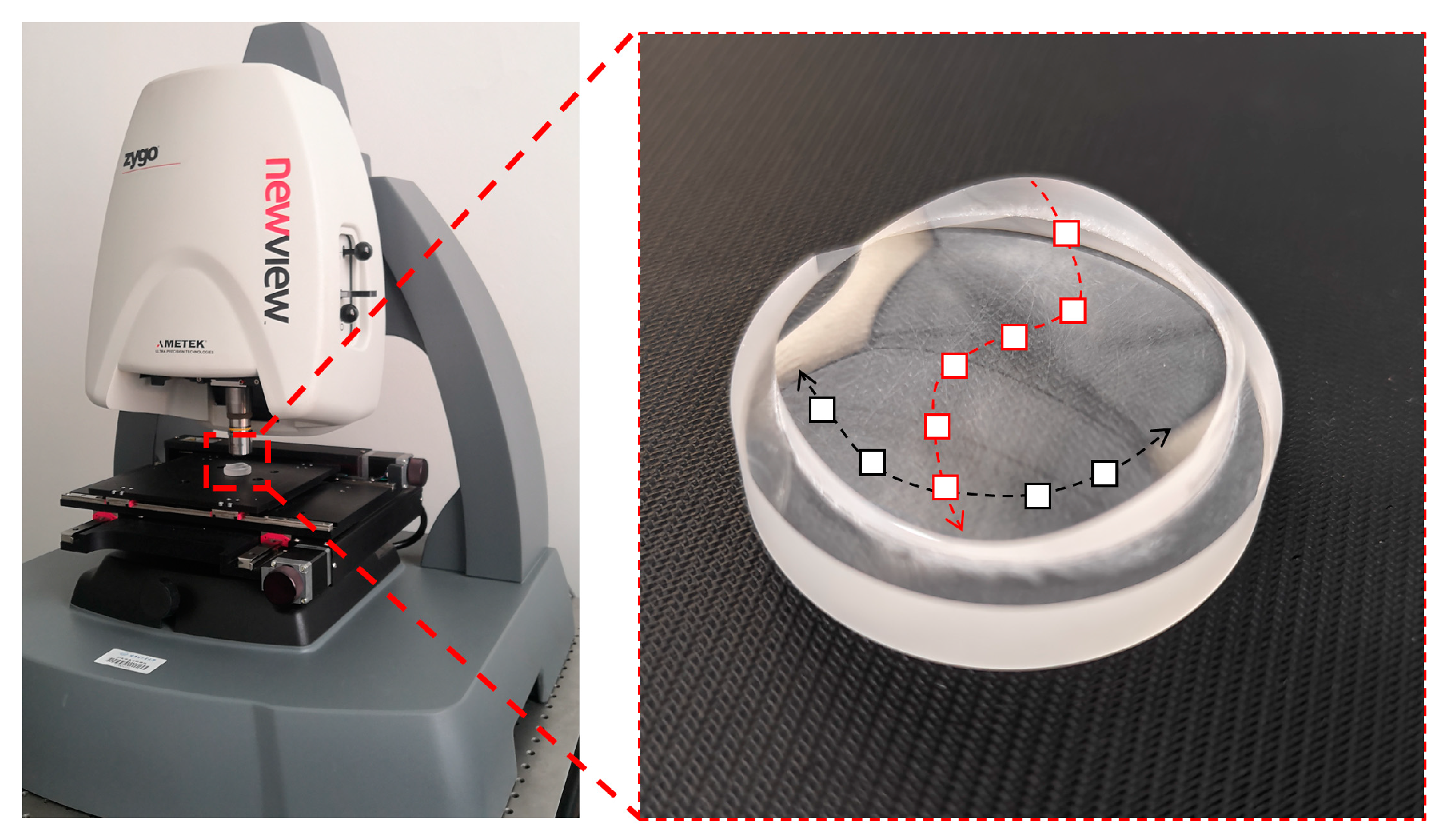
The white-light interferometer (Zygo NewView, Zygo, Middlefield, CT, USA) was employed to measure the surface quality of the machined surfaces on the freeform optical surfaces produced during machining trials. However, constrained by the measurement field of view of the white-light interferometer, it was impossible to perform a comprehensive measurement of the entire freeform surface; only a sampling measurement of the machined surfaces could be conducted. The results obtained through this measurement method inevitably contained measurement errors. Concurrently, the inherent complexity of freeform surfaces renders precise measurement across all regions challenging. To address these limitations, this study employs separate measurement protocols for concave and convex regions of the freeform optical surface. This approach aims to mitigate measurement uncertainty. As illustrated in Figure 3, the red and black paths are schematic diagrams of the measurement paths along the radial and axial directions of the machined surface, respectively.the measurement strategy for machined freeform surfaces involves equidistant sampling along radial and circumferential distributions of the machining path, ensuring coverage of regions with maximum curvature variation. Each region is measured three times to reduce sampling bias and random measurement error.
Figure 3.
The collection strategy of freeform surface measurement.
5. Results and Discussion
To investigate the influencing mechanisms on the surface quality of freeform optical surfaces and to elucidate the differences in surface roughness between concave and convex regions of such surfaces. Based on the results of ultra-precision turning machining experiments, the experimental results are presented in Table 2.
Table 2.
Experimental results of ultra-precision turning.
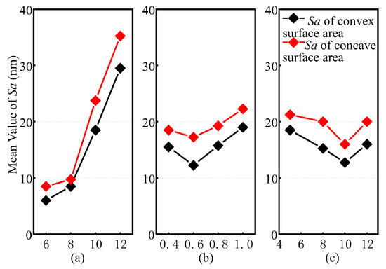
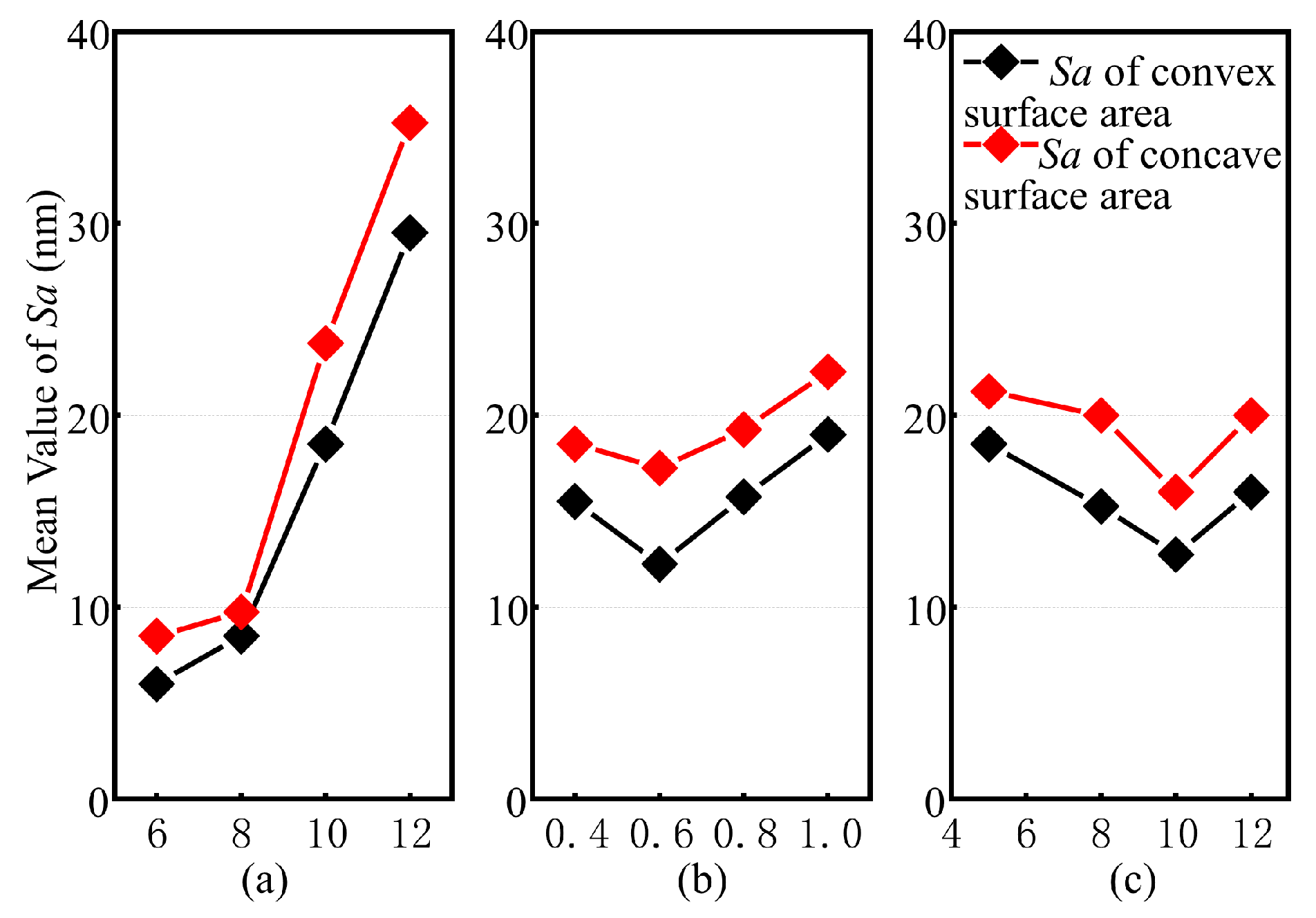
Figure 4 illustrates the variation in three-dimensional surface roughness Sa with respect to machining parameters. The main effect values in Figure 4 were calculated from the measured results of different regions on the freeform surface under various process parameters listed in Table 2. The calculation of the principal effect value is performed with the help of the software Minitab 19. Evidently, in the case of ultra-precision turning of freeform optical surfaces, a significant disparity exists in the three-dimensional surface roughness Sa between the concave and convex surface regions of the machined surface. However, the trend in Sa variation between these different regions is fundamentally consistent. Compared to other machining parameters, the radial feed rate exerts the most pronounced influence on Sa. The remaining two machining parameters exert relatively minor effects on Sa, and their influence on Sa is comparable.
Figure 4.
Main effects plot for Sa: (a) Radial feed rate; (b) Angular increment; (c) Cutting depth.
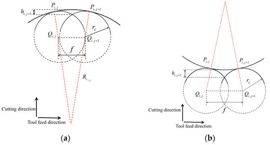
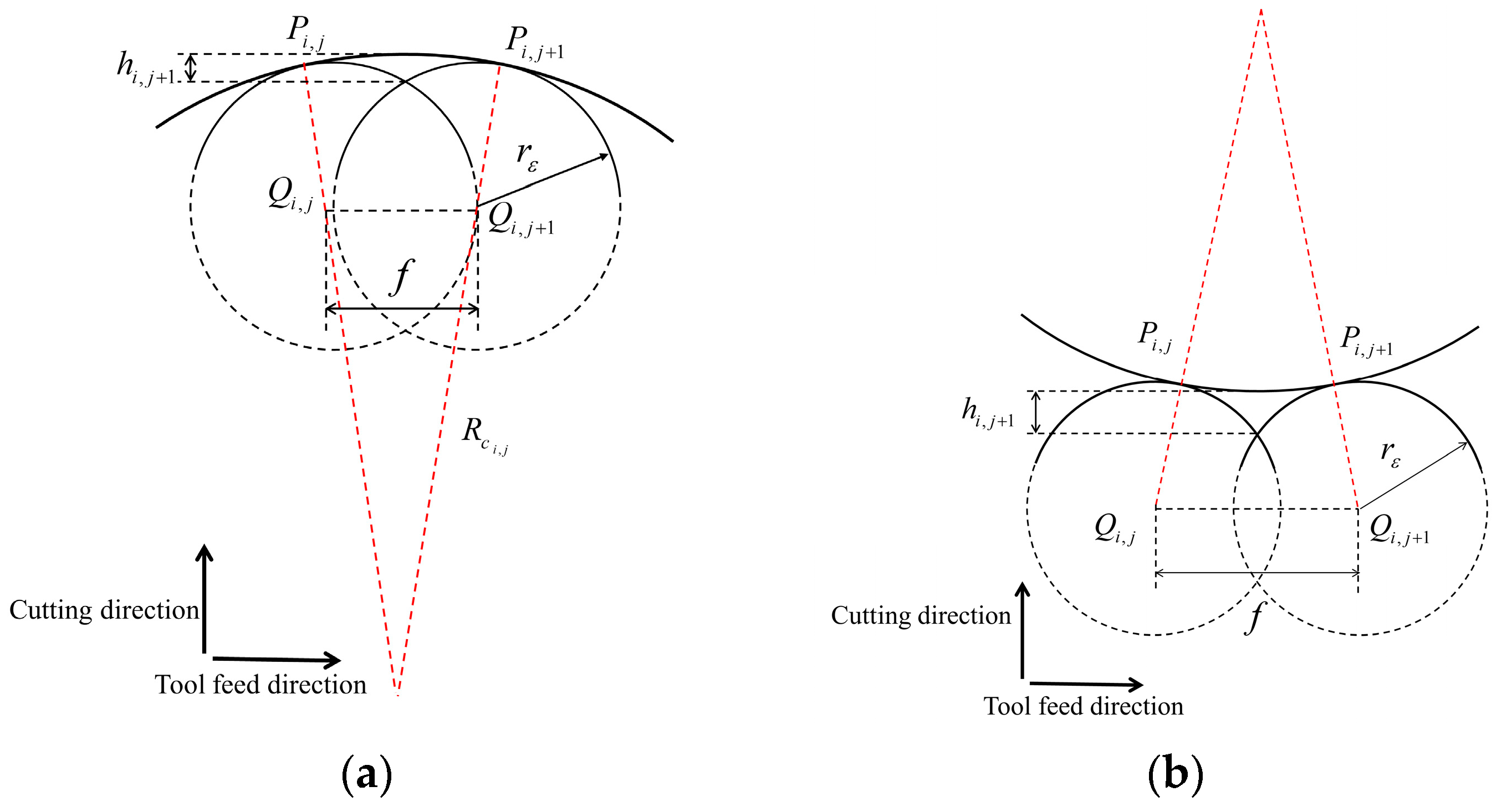
As illustrated by Figure 4a, when the radial feed rate increases from 6 μm/rev to 8 μm/rev, the value of Sa exhibits a gradual increase. However, as the radial feed rate increases beyond 8 μm/rev, the value of Sa rises sharply, with the rate of increase significantly exceeding that of the preceding phase. It is not possible to directly establish a relationship between three-dimensional surface roughness and ultra-precision turning parameters with Equations (1) and (2). Therefore, this paper introduces the parameter residual height (h) to analyse the experimental results. Residual height refers to the height remaining on the machined surface along the radial direction between adjacent tool cutting paths during ultra-precision turning, as illustrated in Figure 5. Figure 5a,b show the residual height between the adjacent tool cutting trajectories of the convex surface region and the concave surface region, respectively. The method for determining the convexity and concavity properties of free-form surfaces is detailed in Figure S1 of the Supplementary Materials. The mathematical relationship between residual height and ultra-precision turning parameters are shown as follows.
where represents the surface curvature (mm) of the contact point of the diamond tool in the convex or concave surface area, represents the tool nose radius (mm) of the diamond tool, and f represents the radial feed (μm).
Figure 5.
The schematic diagram of the residual height in the ultra-precision turning: (a) concave surface; (b) convex surface.
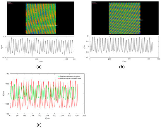
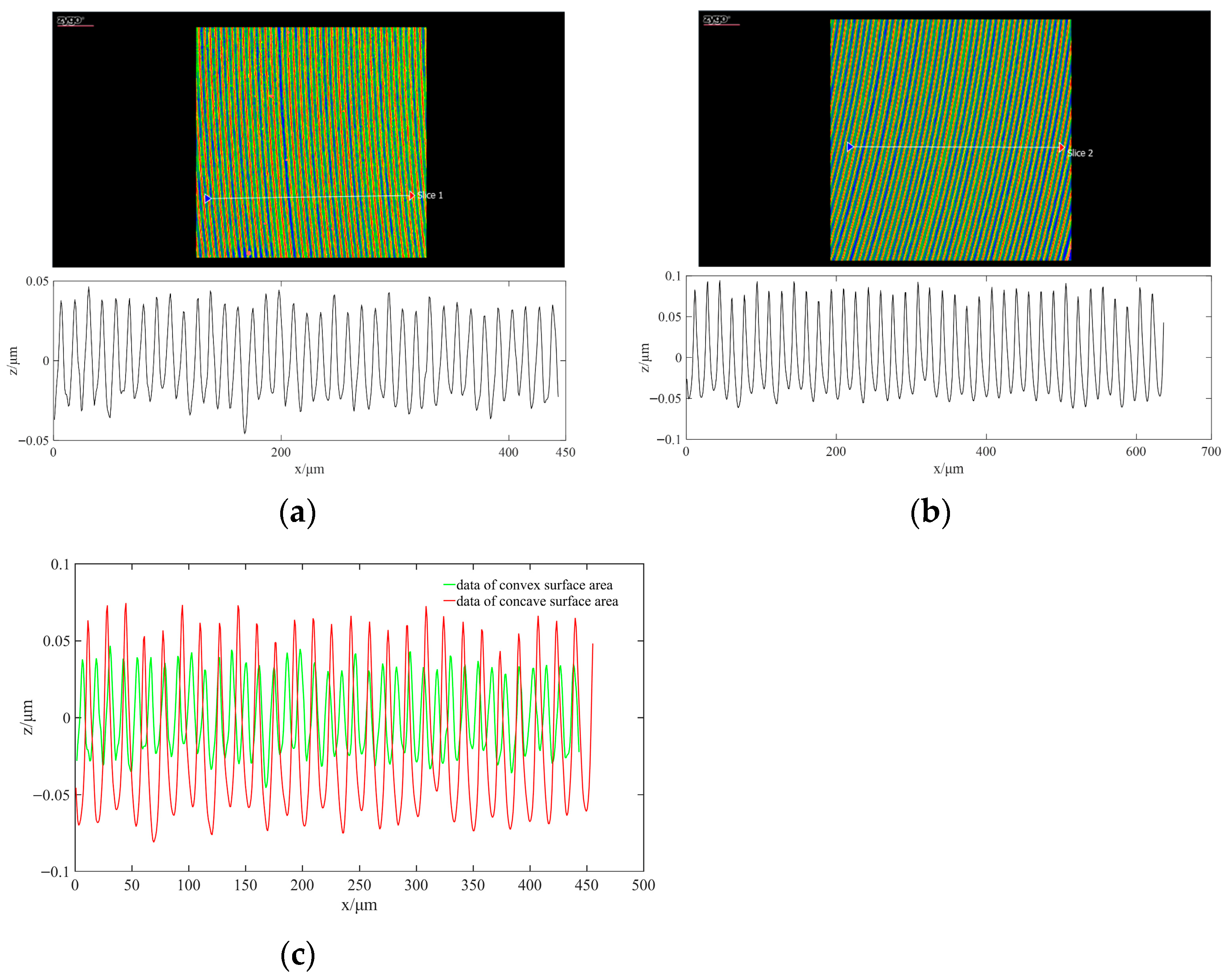
Combining Equations (3) and (4) for analysis, under ideal conditions, the significant difference between tool residual heights and in the concave and convex surface regions during ultra-precision turning arises from variations in surface curvature across different machining regions. Further measurements and analyses were conducted on distinct regions of the free-form surface. Measurements were taken on both the concave and convex surface areas of machined surface No. 16, with results presented in Figure 6. Figure 6a displays the measurement results for the convex surface area, Figure 6b for the concave surface area, and Figure 6c provides a comparative analysis of tool residual heights across different regions. Analysis of the tool residual height across cross-sections of the measured regions revealed variations in radial tool residual height, thereby validating the theoretical analysis. This elucidates the formation mechanism of residual height differences between distinct regions on ultra-precision turned surfaces under ideal conditions. However, the formation of surface topography in ultra-precision turning constitutes a complex process involving multiple coupled factors. Consequently, this analysis provides a qualitative examination of the surface topography in ultra-precision turning. Residual height exhibits a positive correlation with the machined surface topography. Consequently, a lower radial feed rate yields a higher quality machined surface. However, it is noteworthy that for ultra-precision slow-cutting servo turning, a reduced radial feed rate entails a longer machining duration, which diminishes machining efficiency. Conversely, an excessively prolonged machining time accelerates tool wear, thereby altering the material removal mechanism and degrading the quality of the freeform machined surface. As shown in Figure 4b, the three-dimensional surface roughness Sa attains its minimum value when the angular increment is 0.6 deg/ms. This sufficiently small angular increment enhances tool path resolution, thereby improving the surface quality of the machined surface. Continuously increasing spindle speed accelerates tool wear, altering the material removal mechanism and degrading machined surface quality. As shown in Figure 4c, the minimum three-dimensional surface roughness Sa is achieved at a cutting depth of 10 μm. When the cutting depth falls below this chip thickness, ploughing and extrusion effects between the tool cutting edge and workpiece compromise surface finish quality.
Figure 6.
Measurement results of different regions of the machined surface: (a) convex surface; (b) concave surface; (c) the comparison of tool residual heights.
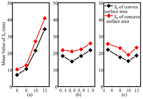
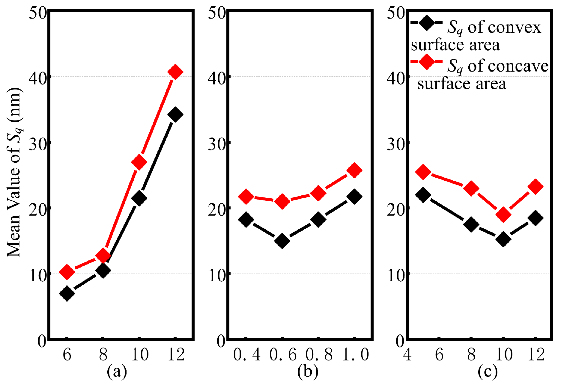
Figure 7 shows the variation in surface roughness Sq with processing parameters. Compared with Sa, the change trend of Sq under the same processing conditions is basically the same as that of Sa. Therefore, Sq can be further used to evaluate the surface quality of freeform optical surfaces.
Figure 7.
Main effects plot for Sq: (a) Radial feed rate; (b) Angular increment; (c) Cutting depth.
The stability and reliability of optical performance in freeform optical components depend upon the uniformity of surface quality. The intricate surface features of freeform surfaces can result in non-uniformity across the entire machined surface, which can degrade the optical performance of optical components. The analysis of orthogonal experimental data indicates a significant difference in surface roughness between concave and convex regions of freeform surfaces. This finding indicates that the surface quality of freeform surfaces is non-homogeneous. Such surface quality variations can adversely affect the optical performance of freeform optical components. To achieve stable manufacturing of freeform optical components, establishing appropriate evaluation parameters for quantitative analysis of freeform surface quality is crucial. Consequently, this paper proposes a novel method for quantifying the uniformity of surface quality. A new set of surface quality evaluation parameters, Sau and Squ, is introduced to perform quantitative analysis of the overall surface quality uniformity of machined freeform surfaces. The evaluation parameters Sau and Squ represent the difference in surface roughness between the concave and convex regions of the freeform surface. The calculation method is outlined below.
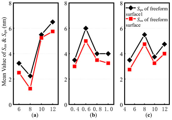
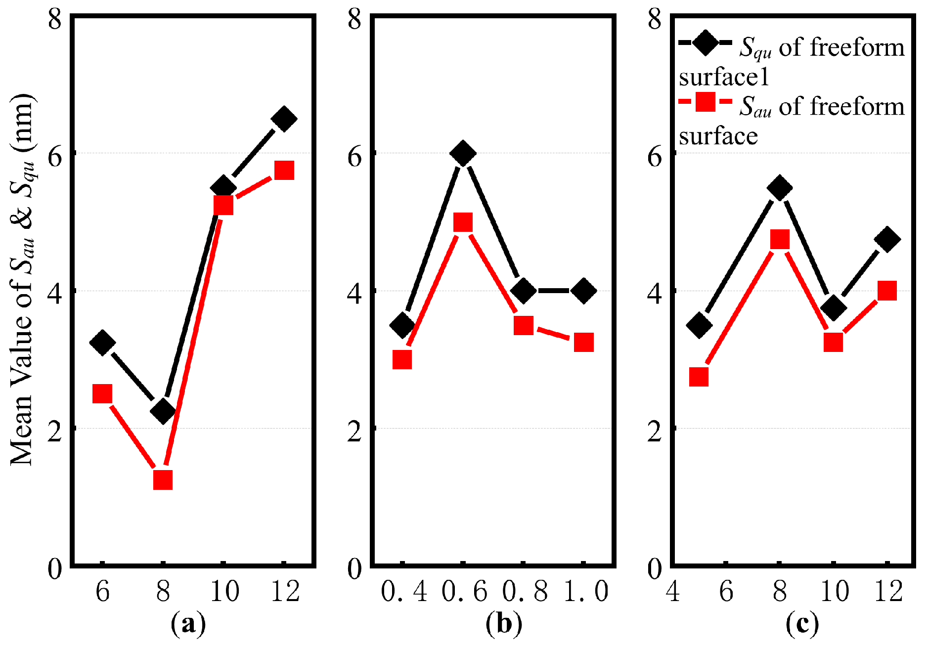
The results of the uniformity of surface roughness of freeform surface are shown in Figure 8. Compared with the findings from the preceding section, the differences in overall surface quality uniformity across the freeform surface are relatively minor for varying machining parameters. As shown in Figure 8a, the radial feed rate exerts the most significant influence on the uniformity of the freeform surface’s overall surface quality. Moreover, this uniformity exhibits considerable fluctuation as the radial feed rate increases. Optimal uniformity of the freeform surface element’s surface quality is achieved at a radial feed rate of 8 μm/rev. This indicates the most stable surface quality for freeform optical surface elements. As illustrated in Figure 8b, the difference in surface roughness remains within a narrow range for angular increments of both 0.4 deg/ms and 1 deg/ms. In Figure 8c, the difference in surface roughness reaches its minimum at a cutting depth of 5 μm. Both parameters exert a relatively stable influence on the uniformity of the freeform surface’s overall surface quality. Consequently, more efficient machining parameters may be explored during production to enhance processing efficiency.
Figure 8.
The uniformity of surface roughness of freeform surface: (a) Radial feed rate; (b) Angular increment; (c) Cutting depth.
Based on the evaluation method for the uniformity of surface quality in freeform optical surfaces, this study investigates machining techniques for achieving uniform surface quality in such surfaces. The significant contribution of ultra-precision turning parameters to the overall uniformity of surface quality in freeform surfaces can be evaluated by range analysis value. The range calculation method is as follows:
where Ri is the range of the i th factor, and kij is the average of the j level of the i th factor, i = (1, 2, 3); j = (1, 2, 3, 4). The results of the Range analysis are shown in Table 3 and Table 4.
Table 3.
Range analysis of the results of Sau.
Table 4.
Range analysis of the results of Squ.
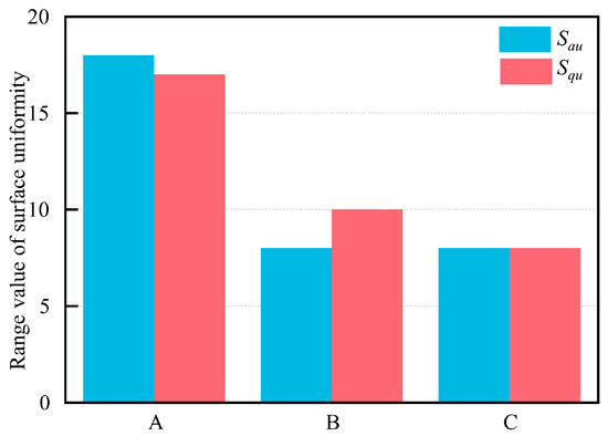
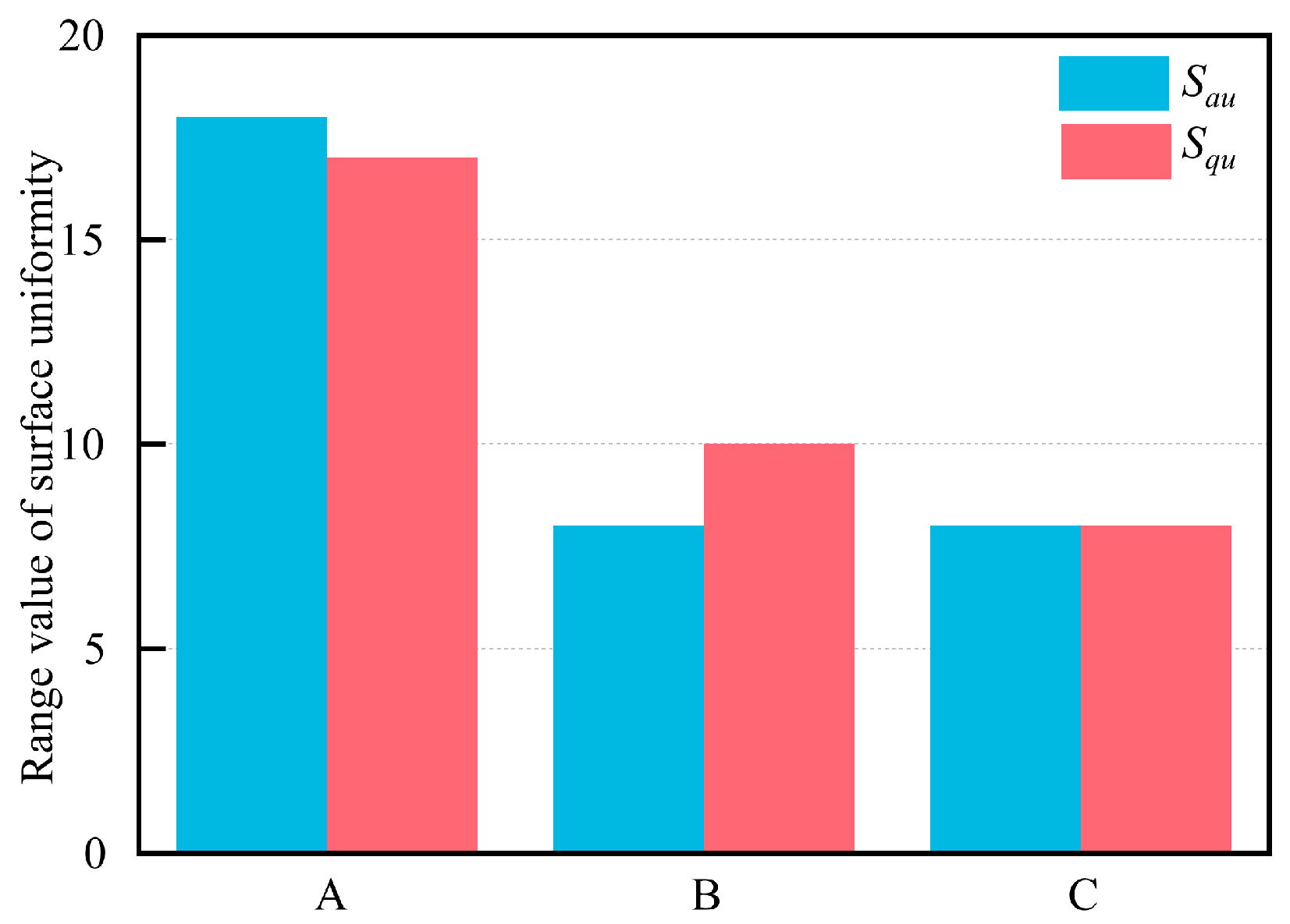
As illustrated in Figure 9, the significance of the influence of machining parameters on the uniformity of the overall surface quality of the freeform optical surface is radial feed rate > angular increment > cutting depth. And the radial feed rate is the primary factor causing non-uniformity in the surface quality of the freeform surface. The angular increment and cutting depth exert effects of comparable magnitude. This finding is consistent with the results of previous studies.
Figure 9.
Range analysis of the uniformity for freeform surface.
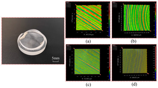
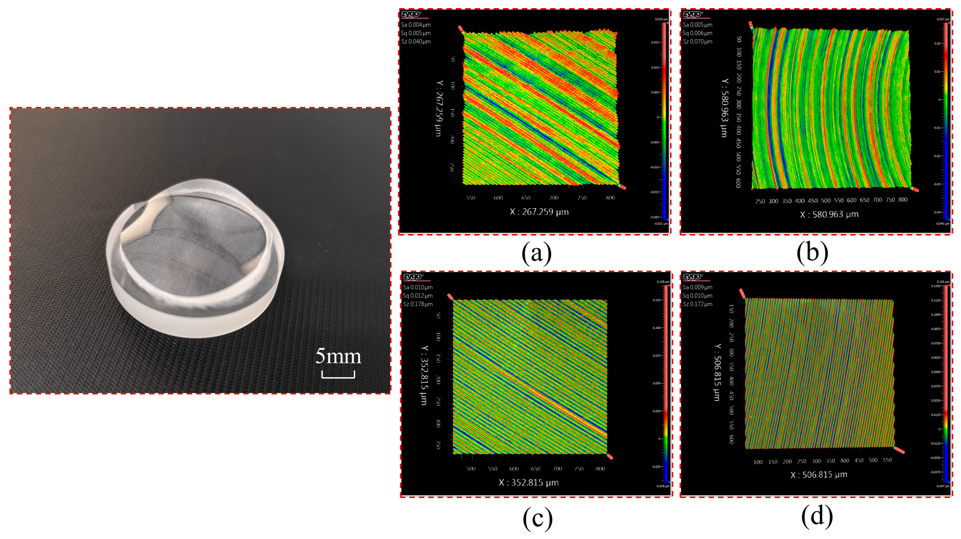
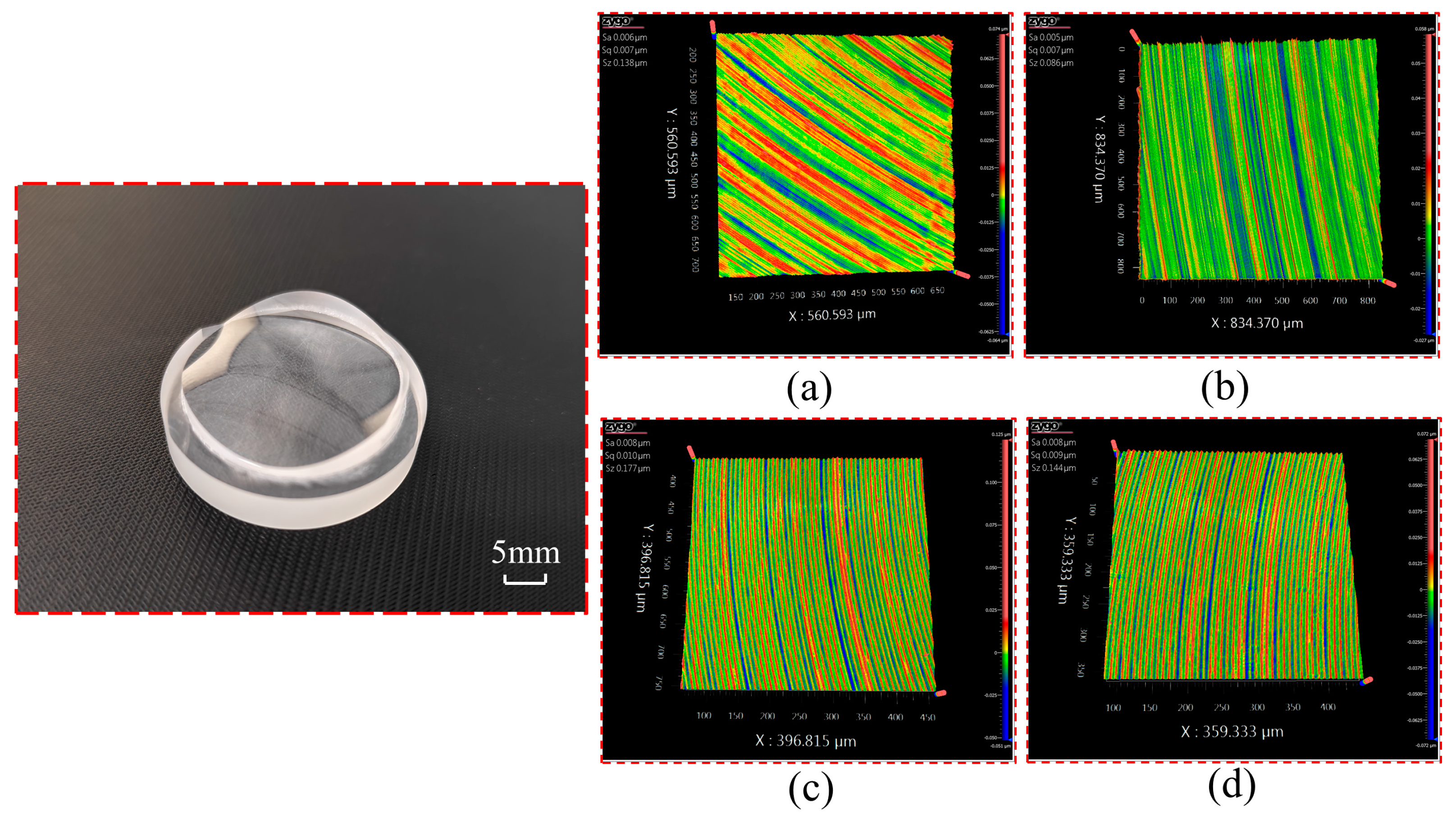
Based on the results of the range analysis, the optimal combination of machining parameters within the experimental range was determined as (radial feed rate = 8 μm/r, angular increment = 0.4 deg/ms, cutting depth = 5 μm). Research indicates that the radial feed rate exerts the most significant influence on the surface quality of freeform surfaces. Consequently, the impact of the radial feed rate warrants further validation. To further investigate machining methods for high-quality freeform optical elements, supplementary machining trials were conducted using a parameter combination with a smaller radial feed rate (radial feed rate= 4 μm/r, angular increment = 0.4 deg/ms, cutting depth = 5 μm) as a comparative machining parameter set. Given the minor influence of angular increment and cutting depth, no additional verification tests were required for these parameters. The freeform optical element machined using the comparative parameter combination is shown in Figure 10, while that produced with the optimal parameter combination is depicted in Figure 11.
Figure 10.
Freeform optical component by comparative combination of machining parameter: (a,b) the measurement results of convex area; (c,d) the measurement results of concave area.
Figure 11.
Freeform optical component by optimal combination of machining parameters: (a,b) the measurement results of convex area; (c,d) the measurement results of concave area.
Further experiments were conducted on the ultra-precision turning of freeform surfaces, generating PMMA freeform optical surfaces using two sets of machining parameter combinations. Measurement results from different regions of the machined surfaces are shown in Figure 10 and Figure 11. Figure 10a and Figure 11a display surface measurement results for convex regions of the freeform surface, while Figure 10d and Figure 11d present measurements for concave regions. Figure 10a and Figure 11a reveal lower surface roughness achieved in convex areas, specifically Sa = 4 nm and Sq = 5 nm. This further validates the influence of radial feed rate on the surface quality of freeform surfaces. However, as depicted in Figure 10c,d, the maximum surface roughness values in the concave regions reached Sa =10 nm and Sq = 12 nm. This indicates significant variations in surface quality across different areas of the freeform surface. Further calculations using the surface quality uniformity evaluation parameters proposed herein yielded Sau = 5 and Squ = 5.5. Comparing with Figure 8a, it can be concluded that the uniformity of surface quality across the freeform surface deteriorates. The measurement results align with the evaluation parameter analysis, validating the feasibility of the proposed surface quality uniformity assessment method. The measurement results in Figure 11a–d demonstrate that the surface roughness difference between the concave and convex regions of the freeform surface can be stably maintained within 3 nm. Concurrently, calculations based on the proposed surface quality uniformity evaluation parameters yield Sau = 2.5 and Squ = 2.5. Comparison with Figure 8a indicates that the overall surface quality uniformity of the freeform surface has achieved a satisfactory standard. The contrast between the surface quality results and evaluation parameters obtained from both sets of machining parameter combinations further validates the reliability of the proposed evaluation parameters.
6. Conclusions
In this study, nano-scale surface roughness test of PMMA optical components was carried out by ultra-precision slow tool servo turning. The surface roughness and the uniformity of the overall surface quality of the ultra-precision turning of freeform optical surface components are analysed and studied. The following conclusions can be obtained.
- (1)
- The results of machining trials indicate a significant disparity in surface roughness between concave and convex regions on PMMA freeform optical surfaces produced via ultra-precision turning. Analysis incorporating surface roughness modelling reveals the mechanism underlying these variations across different areas of the freeform optical surface. Research demonstrates that radial feed rate exerts the most pronounced influence on the surface roughness of freeform optical surface components, whilst angular increment and cutting depth exert comparatively minor effects.
- (2)
- A novel surface quality evaluation method has been proposed to assess the uniformity of the overall surface quality of freeform optical surfaces. This further reveals the influence of radial feed rate on the uniformity of the overall surface quality of freeform optical surfaces. Unlike its effect on the local surface roughness of freeform optical surfaces, the uniformity of the overall surface quality of freeform optical surfaces achieves its optimum when the radial feed rate is set to 8 μm/rev.
- (3)
- High-performance ultra-precision turning of PMMA freeform optical surfaces was carried out. Optimal machining parameter combinations were selected and validated against research findings. Concurrently, further experimental verification was conducted on radial feed rates. Ultimately, the fabrication of a nano-scale PMMA freeform optical surface with uniformly consistent surface quality was achieved. Surface roughness variations across different regions of the machined freeform optical surface remained stable within 2–3 nm.
Supplementary Materials
The following supporting information can be downloaded at: https://www.mdpi.com/article/10.3390/app16031350/s1, Figure S1. Flowchart for Assessing the Concavity and Convexity Properties of Free-Form Surfaces.
Author Contributions
Conceptualization, X.W.; methodology, X.W.; software, X.W.; validation, X.W., L.Z. and Q.B.; formal analysis, X.W.; investigation, X.W.; resources, Q.B.; data curation, X.W. and L.Z.; writing—original draft preparation, X.W.; writing—review and editing, Q.B. and K.C.; visualisation, X.W.; supervision, Q.B. and K.C.; project administration, Q.B.; funding acquisition, Q.B. All authors have read and agreed to the published version of the manuscript.
Funding
This work was supported by National Natural Science Foundation of China (Grant numbers [U2430215]).
Institutional Review Board Statement
Not applicable.
Informed Consent Statement
Not applicable.
Data Availability Statement
The raw data supporting the conclusions of this article will be made available by the authors on request.
Acknowledgments
Thanks are due to Yan Gu for assistance with the experiments.
Conflicts of Interest
The authors declare no conflicts of interest.
References
- Zhang, Y.; Sun, H.; Chen, Y.; Zhang, Z.; Zheng, X.; Xu, Y.; She, J.; Wu, R. Flexible intensity and wavefront shaping with freeform optics. Opt. Lett. 2025, 50, 6317–6320. [Google Scholar] [CrossRef] [Scilit]
- Luna Palacios, Y.Y.; Hoang, T.N.A.; Khandani, S.; Clark, S.; Bauer, A.; Rolland, J.P.; Potma, E.O.; Hanninen, A.M. Nonlinear optical microscopy with an obscuration-free, freeform reflective objective. Biomed. Opt. Express 2025, 16, 4530–4540. [Google Scholar] [CrossRef] [Scilit]
- Wu, S.; Wang, J.; Miao, L.; Wang, Z.; Fang, F. Freeform off-axis three-mirror anastigmatic system for deep ultraviolet femtosecond laser processing. Appl. Opt. 2025, 64, 9380–9390. [Google Scholar] [CrossRef] [Scilit]
- Ochs, L.; Davies, M.A.; Dutterer, B.S.; Bauer, A.; Rolland, J.P.; Boreman, G.D. Optical image quality testing and correction of a 250-mm freeform telescope. Opt. Contin. 2025, 4, 59. [Google Scholar] [CrossRef] [Scilit]
- Zhang, Z.; Zhang, Z.; Fang, X.; Liu, S.; Liu, Z.; Zheng, J.; Zhao, R.; Wang, H.; She, J.; Li, H.; et al. Miniaturized-voxel light field panel display based on an ultra-slim and large-area freeform directional backlight. Optica 2025, 12, 8. [Google Scholar] [CrossRef] [Scilit]
- Liu, J.; Jiang, P.; Yang, H.; Wang, D. A beam shaping and collimation technique using freeform optics optimized by NSGA-II. Opt. Commun. 2025, 596, 132411. [Google Scholar] [CrossRef] [Scilit]
- Demirhan, Y.; Anil, D.; Akaoğlu, B. Correcting conformal dome optical aberrations by using a rotating freeform optical element. Appl. Opt. 2025, 64, 8671. [Google Scholar] [CrossRef] [Scilit]
- Hou, C.; Yu, Y.; Zhang, D.; Liu, X.; Jin, K.; Shi, Z.; Zhao, J.; Cui, G. Miniature wide angle optical system with freeform lens. Opt. Rev. 2024, 31, 497–508. [Google Scholar] [CrossRef] [Scilit]
- Yan, Y.; Zhou, P.; Wang, H.; Mao, Y. Thermal Effect on Poly(methyl methacrylate) (PMMA) Material Removal in the Micromilling Process. Polymers 2020, 12, 2122. [Google Scholar] [CrossRef] [Scilit] [PubMed]
- Xing, Y.; Xue, C.; Liu, Y.; Du, H.; Yip, W.S.; To, S. Freeform surfaces manufacturing of optical glass by ultrasonic vibration-assisted slow tool servo turning. J. Mater. Process. Technol. 2024, 324, 118271. [Google Scholar] [CrossRef] [Scilit]
- Zhu, Z.; To, S. Adaptive tool servo diamond turning for enhancing machining efficiency and surface quality of freeform optics. Opt Express 2015, 23, 20234–20248. [Google Scholar] [CrossRef] [Scilit]
- Zhang, C.; Cheung, C.-F.; Liang, X.; Bulla, B. A Theoretical and Experimental Investigation of High-Frequency Ultrasonic Vibration-Assisted Sculpturing of Optical Microstructures. Appl. Sci. 2022, 12, 10937. [Google Scholar] [CrossRef] [Scilit]
- Kong, L.B.; Cheung, C.F. Design, fabrication and measurement of ultra-precision micro-structured freeform surfaces. Comput. Ind. Eng. 2011, 61, 216–225. [Google Scholar] [CrossRef] [Scilit]
- Hatefi, S.; Abou-El-Hossein, K. Review of single-point diamond turning process in terms of ultra-precision optical surface roughness. Int. J. Adv. Manuf. Technol. 2019, 106, 2167–2187. [Google Scholar] [CrossRef] [Scilit]
- Han, J.; Chen, Y.; Wang, J.; Zhang, G.; Wang, H. A review of molecular dynamics simulation in studying surface generation mechanism in ultra-precision cutting. Int. J. Adv. Manuf. Technol. 2022, 122, 1195–1231. [Google Scholar] [CrossRef] [Scilit]
- Liu, J.; Wang, S.; Zhao, Q.; Zhang, Q.; Kang, Z.; Wu, T.; He, P.; Cao, C.; Xu, Z. Study on ultra-precision diamond cutting of polymers: Factors affecting dimensional accuracy and material removal mechanism. Polymer 2024, 309, 127456. [Google Scholar] [CrossRef] [Scilit]
- He, C.L.; Zong, W.J. Influencing factors and theoretical models for the surface topography in diamond turning process: A review. Micromachines 2019, 10, 288. [Google Scholar] [CrossRef] [Scilit]
- Zhou, X.; Liu, H.; Yu, T.; Guo, R.; Wang, G.; Sun, Y.; Chen, M. Experimental and modeling study of surface topography generation considering tool-workpiece vibration in high-precision turning. Chin. J. Aeronaut. 2023, 36, 194–212. [Google Scholar] [CrossRef] [Scilit]
- Cao, Y.; Zhao, X.; Li, G.; Zong, W.; Sun, T. Study regarding the influence of process conditions on the surface topography during ultra-precision turning. J. Manuf. Process. 2023, 102, 23–36. [Google Scholar] [CrossRef] [Scilit]
- Cheung, C.F.; Lee, W.B. Study of factors affecting the surface quality in ultra-precision diamond turning. Mater. Manuf. Process. 2000, 15, 481–502. [Google Scholar] [CrossRef] [Scilit]
- Huang, K.; Gong, H.; Chen, X. Study of ultra-precision turning path calculation of freeform surface with free contours. Int. J. Adv. Manuf. Technol. 2022, 121, 5451–5462. [Google Scholar] [CrossRef] [Scilit]
- Lee, W.B.; Cheung, C.F. A dynamic surface topography model for the prediction of nano-surface generation in ultra-precision machining. Int. J. Mech. Sci. 2001, 43, 961–991. [Google Scholar] [CrossRef] [Scilit]
- Wang, H.; To, S.; Chan, C.Y. Investigation on the influence of tool-tip vibration on surface roughness and its representative measurement in ultra-precision diamond turning. Int. J. Mach. Tools Manuf. 2013, 69, 20–29. [Google Scholar] [CrossRef] [Scilit]
- Khaghani, A.; Cheng, K. Investigation on multi-body dynamics based approach to the toolpath generation for ultraprecision machining of freeform surfaces. Proc. Inst. Mech. Eng. Part B J. Eng. Manuf. 2019, 234, 571–583. [Google Scholar] [CrossRef] [Scilit]
- He, S.; Xuan, J.; Du, W.; Xia, Q.; Xiong, S.; Zhang, L.; Wang, Y.; Wu, J.; Tao, H.; Shi, T. Spiral tool path generation method in a NURBS parameter space for the ultra-precision diamond turning of freeform surfaces. J. Manuf. Process. 2020, 60, 340–355. [Google Scholar] [CrossRef] [Scilit]
- Prasad, K.K.; Singh, M.P.; Negi, V.S.; Mishra, V.; Jha, S.; Khan, G.S. Ductile machining of single-crystal germanium freeform optics via ultra-precision diamond turning for high-performance infrared imaging systems. Precis. Eng. 2025, 96, 380–397. [Google Scholar] [CrossRef] [Scilit]
- Huang, W.; Yan, J. Effect of tool geometry on ultraprecision machining of soft-brittle materials: A comprehensive review. Int. J. Extrem. Manuf. 2023, 5, 012003. [Google Scholar] [CrossRef] [Scilit]
- Li, C.; Zhao, G.; Ji, D.; Zhang, G.; Liu, L.; Zeng, F.; Zhao, Z. Influence of tool wear and workpiece diameter on surface quality and prediction of surface roughness in turning. Metals 2024, 14, 1205. [Google Scholar] [CrossRef] [Scilit]
- Tang, Y.; Ying, R.; Liu, Y.; Cui, H.; Qiu, L.; Zhao, W. Research on freeform surface detection by high precision normal measurement method based on laser confocal fixed-focus. Opt. Lasers Eng. 2025, 194, 109210. [Google Scholar] [CrossRef] [Scilit]
- Liu, S.; Cheng, K. Investigation on the surface texture aspect ratio of freeform surfaced optics and its correlation with the optical performance. Proc. Inst. Mech. Eng. Part B J. Eng. Manuf. 2024, 239, 2134–2142. [Google Scholar] [CrossRef] [Scilit]
- Cheung, C.F.; Li, H.F.; Lee, W.B.; To, S.; Kong, L.B. An integrated form characterization method for measuring ultra-precision freeform surfaces. Int. J. Mach. Tools Manuf. 2007, 47, 81–91. [Google Scholar] [CrossRef] [Scilit]
- Wang, X.; Bai, Q.; Gao, S.; Zhao, L.; Cheng, K. A Toolpath Planning Method for Optical Freeform Surface Ultra-Precision Turning Based on NURBS Surface Curvature. Machines 2023, 11, 1017. [Google Scholar] [CrossRef] [Scilit]
- Wu, X.; Kang, Q.; Jiang, X.; Fang, X. Machinability and Surface Properties of Cryogenic Poly(methyl methacrylate) Machined via Single-Point Diamond Turning. Materials 2024, 17, 866. [Google Scholar] [CrossRef] [Scilit]
- Li, D.; Qiao, Z.; Walton, K.; Liu, Y.; Xue, J.; Wang, B.; Jiang, X. Theoretical and Experimental Investigation of Surface Topography Generation in Slow Tool Servo Ultra-Precision Machining of Freeform Surfaces. Materials 2018, 11, 2566. [Google Scholar] [CrossRef] [Scilit] [PubMed]

Disclaimer/Publisher’s Note: The statements, opinions and data contained in all publications are solely those of the individual author(s) and contributor(s) and not of MDPI and/or the editor(s). MDPI and/or the editor(s) disclaim responsibility for any injury to people or property resulting from any ideas, methods, instructions or products referred to in the content. |
© 2026 by the authors. Licensee MDPI, Basel, Switzerland. This article is an open access article distributed under the terms and conditions of the Creative Commons Attribution (CC BY) license.