


Abstract
This study investigates the axial compressive performance of carbon-fibre-reinforced polymer (CFRP)-confined pre-damaged recycled aggregate concrete (RAC) square columns. A total of 90 square specimens (100 mm × 100 mm × 300 mm) were tested under monotonic axial compression. Three key variables were considered: pre-damage level (D1 slight, D2 moderate, D3 severe), number of CFRP layers (1, 2, 3), and recycled fine aggregate (RFA) replacement ratio (0%, 50%, 100%), with the recycled coarse aggregate (RCA) replacement ratio fixed at 50%. Pre-damage was induced by pre-loading specimens to 0.9 fco on the ascending branch, peak stress fco, and 0.9 fco on the descending branch, respectively. Failure modes, full stress–strain responses, peak strength, peak strain, and CFRP hoop rupture strain were analysed. Test results show that CFRP confinement effectively restores and enhances both load-carrying capacity and deformability of pre-damaged RAC columns. Higher pre-damage level reduces post-strengthening peak strength. Increasing RFA replacement ratio decreases peak strength yet generally improves ductility. More CFRP layers produce higher strength and better deformation capacity. The average effective hoop rupture strain coefficient of CFRP for square specimens is 0.60. Empirical formulas for predicting peak strength and peak strain are proposed and developed from the present test database. This work provides experimental baseline data for retrofitting of damaged RAC structures using CFRP.
1. Introduction
Recycled aggregate concrete (RAC) is a promising low-carbon construction material for re-utilising demolished concrete waste [1]. Substituting both natural coarse and fine aggregates with recycled counterparts maximises the solid-waste recycling rate compared with only replacing coarse aggregates [2]. Extensive studies have been conducted on the mechanical properties of fibre-reinforced polymer (FRP)-confined RAC under axial compression [3,4,5,6]. However, several research gaps remain. A critical comparison of the existing literature shows that most studies have varied only one factor at a time, either section shape, aggregate type, or initial damage, rather than examining their coupled effects. As a result, the combinations of parameters that have already been covered, and those that remain unresolved, are not yet clearly delineated for pre-damaged square RAC columns.
First, most existing tests focus on circular specimens, whereas real-world frame columns are predominantly square or rectangular in cross-section [7]. Square sections exhibit corner stress concentration, which significantly reduces the effective confining pressure and the FRP utilisation ratio compared with circular sections [8]. Second, the majority of the published literature investigates intact RAC without initial damage [9]. In practice, structural columns subjected to earthquake, impact, or long-term service loads develop internal cracks and even surface spalling before FRP retrofitting is applied [10]. The presence of pre-existing damage alters the confinement mechanism and reduces the effectiveness of FRP strengthening. Third, experimental data for FRP-confined RAC with simultaneous replacement of recycled coarse aggregate (RCA) and recycled fine aggregate (RFA) remain limited. Most studies replace only coarse aggregates, while the coupled effect of RCA and RFA on FRP-confined behaviour is not well understood [11]. Specifically, previous work has mainly addressed CFRP-confined circular RAC with RCA replacement only and no pre-damage [3,4,11], FRP-confined square normal-aggregate concrete with corner-radius effects but without RAC or pre-damage [7,8], and CFRP-strengthened recycled concrete columns with seismic damage but without systematically coupling damage level, CFRP layer number, and RFA ratio [12]. To the best of the authors’ knowledge, the combination examined here, namely RCA fixed at 50%, RFA replacement of 0%, 50%, and 100%, three pre-damage levels, and one to three CFRP layers on square columns, has not been systematically reported, which is the specific novelty of this study.
After seismic events, concrete in plastic hinge zones develops cracks and partial spalling, entering the descending portion of the compressive stress–strain curve. CFRP wrapping is a widely adopted retrofitting technique for damaged concrete members due to its high strength-to-weight ratio, corrosion resistance, and ease of application [9,13,14]. For pre-damaged square RAC columns, the coupled effects of initial damage severity, CFRP confinement stiffness, and RFA content on mechanical behaviour are still not fully understood, restricting practical retrofitting design.
In the present work, 90 square column specimens were manufactured and pre-damaged at three damage levels, then strengthened with 1–3 layers of CFRP, with RFA replacement ratios of 0%, 50%, and 100% (RCA fixed at 50%). Monotonic axial compression tests were performed. This paper aims to (1) characterise failure patterns and full-range stress–strain behaviour; (2) quantify the combined influence of pre-damage, CFRP layers, and RFA ratio on peak strength and peak strain; (3) obtain the effective CFRP hoop rupture strain coefficient for square sections; (4) propose empirical prediction equations for CFRP-confined pre-damaged RAC square columns; and (5) discuss the limitations and applicability boundaries of the findings. The obtained average effective hoop rupture strain coefficient (0.60) is consistent with the 0.50 to 0.65 range reported for CFRP-confined square normal-aggregate concrete and the 0.55 to 0.62 range for intact RAC square columns, whereas the strength enhancement ratio (1.04 to 1.27) is lower than the 1.15 to 1.40 typically reported for CFRP-confined intact normal-aggregate square columns with equivalent confinement stiffness, which is attributable to the combined effects of pre-damage and RAC ITZ weakness. The outcomes can support retrofitting design for damaged RAC building components.
2. Experimental Program
2.1. Specimen Design
Prismatic square columns with a cross-section of 100 mm × 100 mm and a height of 300 mm were prepared, totalling 90 specimens. Eighteen 150 mm standard cubic specimens were cast to obtain the basic compressive properties of each concrete mix. Three experimental variables were considered:
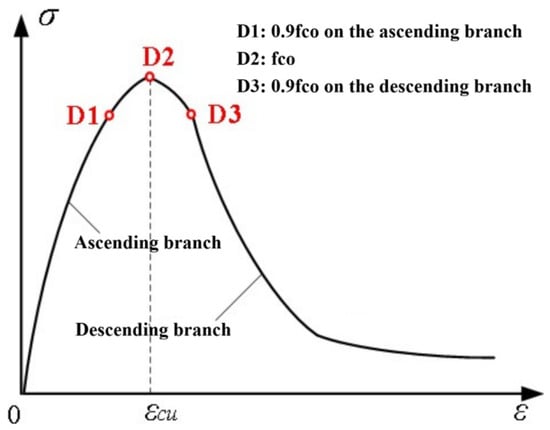
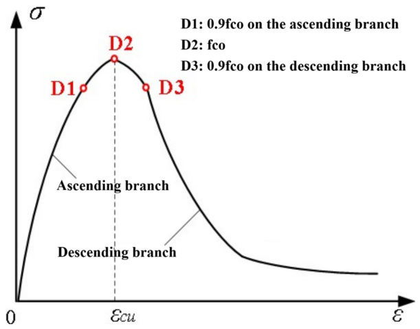
(1) Pre-damage level: D1 (slight damage)—pre-loaded to 0.9 fco on the ascending branch then unloaded; D2 (moderate damage)—pre-loaded to peak compressive stress fco then unloaded; D3 (severe damage)—pre-loaded to 0.9 fco on the descending branch then unloaded. Here, fco is the peak compressive strength of the corresponding undamaged RAC prism. A reference undamaged group (D0) without pre-loading was also prepared for quantitative comparison to separate material-induced degradation from pre-loading-induced degradation. The D1–D3 levels are defined as pre-loading history positions on the measured stress–strain curve rather than as quantitative residual-damage indices; this definition ensures repeatability under displacement control and is sufficient for comparing the relative effects of pre-damage, CFRP layers, and RFA ratio. For each concrete mix, the target points were located on the average stress–strain curve obtained from the companion prism tests. The D1 target was the point on the ascending branch where the stress reached 0.9 fco. The D2 target was the peak point of the curve. The D3 target was the point after the peak where the stress had fallen to 0.9 fco and the tangent slope was negative; this descending-branch point was identified on the real-time stress–strain curve displayed by the testing machine and was confirmed by the simultaneous decrease in load with increasing displacement. Because the same companion-prism average curve was used for each mix, the three target points were located consistently for all specimens of that mix. The corresponding axial strain at each target point was read from the real-time curve during pre-loading, but it was not treated as an independent controlled variable or separately tabulated, because it is mix-specific and the pre-damage levels are defined by stress thresholds rather than by prescribed strain values. Residual deformation and stiffness degradation after unloading were not measured, because reloading to obtain these indices would alter the pre-damage state and introduce secondary disturbance before CFRP wrapping; unloading was therefore performed immediately in displacement control without a reloading cycle. The three damage states were further evidenced by the crack patterns in Section 2.4: D1 showed scarce surface microcracks, D2 showed visible microcracks, and D3 showed multiple penetrating longitudinal cracks with local surface spalling. These observations indicate that the three pre-damage levels represent consistent loading-history states for the present comparative study, although they are not presented as statistically repeatable material-damage indices. The damage definition is illustrated in Figure 1.
Figure 1.
Diagram of pre-damage levels from the compressive stress–strain curve of RAC.
(2) CFRP layers: 1 layer (L1), 2 layers (L2), and 3 layers (L3). Full hoop wrapping with a 100 mm overlap length was applied. Additional 30 mm-wide CFRP strips were placed at both column ends to prevent premature end-crushing failure [14,15].
(3) Recycled fine-aggregate replacement ratio: the RCA replacement ratio was fixed at 50%; RFA replacement ratios were 0% (RFA0), 50% (RFA50), and 100% (RFA100).
Specimen nomenclature example: RFA50-D2-L2 represents a specimen with 50% RFA replacement, moderate D2 damage, and 2-layer CFRP confinement.
The 27 CFRP-confined pre-damaged specimens listed in Table 1 correspond to 27 distinct combinations of pre-damage level (D1–D3), CFRP layer number (L1–L3), and RFA ratio (RFA0–RFA100). Therefore serves as the complete specimen matrix for these 27 main specimens. The remaining square specimens were companion or auxiliary specimens used for material characterization, undamaged reference, and pre-damage verification, and they were not replicates of the 27 main combinations. Because no replicate specimens were available for each of the 27 main combinations, ANOVA and interaction analysis were not performed; instead, descriptive statistics (group means and coefficients of variation) are reported in Section 3.3, and the mean and standard deviation of the effective rupture-strain coefficient are reported in Section 3.4. The raw test data are available from the corresponding author upon reasonable request.
Table 1.
Mix proportions of C50 RAC (kg/m3).
2.2. Raw Materials and Mix Proportion
Ordinary Portland cement P·O 42.5 was adopted. Natural fine aggregate was river sand (medium sand). Natural coarse aggregate was continuously graded gravel with a maximum particle size of 20 mm. Recycled aggregates were produced by crushing waste C30–C40 concrete [16]. The RCA particle range was 5–20 mm; the RFA particle range was 0–5 mm. The measured 24 h water absorption, apparent density, crushing index, and attached mortar content were as follows: RCA, water absorption 5.2%, apparent density 2410 kg/m3, crushing index 16.8%, attached mortar content 32.5%; RFA, water absorption 8.6%, apparent density 2320 kg/m3, crushing index 21.4%, attached mortar content 38.7%. The recycled aggregates were used in an air-dried condition, and the additional water required to compensate for aggregate absorption was added to the mixing water; the water–cement ratio in Table 1 refers to the effective free-water–cement ratio after this compensation. All cubic and prism specimens were tested at the age of 28 days. Tap water and a polycarboxylate-based superplasticiser were used. The mix proportions for C50 RAC are summarised in Table 1.
The cubic compressive strength results are listed in Table 2. As expected, increasing RFA replacement reduces the cubic compressive strength, from 54.5 MPa at RFA0 to 45.4 MPa at RFA100, attributable to the higher porosity and weaker interfacial transition zones (ITZ) associated with RFAs [17,18].
Table 2.
Cubic compressive strength of C50 RAC.
2.3. Material Mechanical Properties
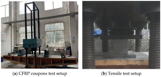
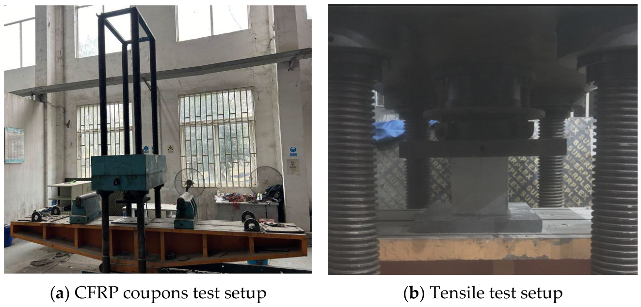
Unidirectional CFRP sheet and matching epoxy impregnation resin were used. CFRP tensile coupon tests (5 replicates) were conducted on a WD-P6 universal testing machine (Jinan PuYe, Jinan, Chinan) (Figure 2). Material properties from the manufacturer datasheet and experimental measurements are given in Table 3, Table 4 and Table 5.
Figure 2.
CFRP coupons and tensile test setup.
Table 3.
Technical indexes of CFRP sheet (manufacturer data).
Table 4.
Properties of epoxy impregnation resin.
Table 5.
Measured tensile properties of CFRP coupons.
2.4. Pre-Damage Procedure and CFRP Wrapping
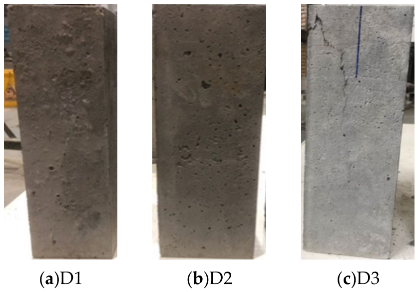
Pre-damage loading was performed on a rigid compression machine with a multi-stage displacement-controlled loading rate given in Table 6. Once the target damage state was reached, unloading was executed immediately. The loading procedure employed displacement control to ensure precise positioning of the target points on the stress–strain curve. For each mix, the average fco from companion prism tests was used as the reference, and the actual unloading point was verified by the real-time stress–strain curve displayed by the test machine. D1 specimens exhibited scarce surface cracks; D2 specimens presented visible microcracks; D3 specimens showed multiple penetrating cracks together with partial surface spalling, as shown in Figure 3. The cracks observed after pre-damage were loading-induced longitudinal splitting cracks parallel to the axial loading direction, rather than shrinkage or thermal cracks. They included interfacial cracks along the aggregate-mortar interface and microcracks within the mortar matrix. D1 specimens showed scarce surface microcracks, D2 specimens showed visible microcracks, and D3 specimens showed multiple penetrating longitudinal cracks accompanied by local surface spalling.
Table 6.
Loading rates for the pre-damage procedure.
Figure 3.
Visual appearance of specimens with different pre-damage levels: (a) D1 slight damage; (b) D2 moderate damage; (c) D3 severe damage.
After unloading, specimens were carefully removed from the testing machine to avoid secondary damage. Loose concrete fragments were removed and dust was cleaned. Fast-setting cement mortar was used to repair spalled regions, followed by 48 h of curing. The repair mortar was applied only to local surface-spalled areas rather than the entire cross-section; its measured compressive strength was approximately 45 MPa. Before CFRP application, the four corners of each square specimen were rounded using a hand grinder to a nominal radius of 10 mm, so as to reduce corner stress concentration and improve confinement efficiency. The concrete substrate was then cleaned with a wire brush and wiped with acetone to remove dust and oil. Surfaces were then polished and cleaned prior to CFRP application. Epoxy resin was brushed on both the concrete substrate and the CFRP sheet. CFRP was wrapped tightly around the square prisms, and air bubbles were expelled with a scraper. The overlap length was kept at 100 mm. End strips of 30 mm width were added. Specimens were cured for 7 days at ambient temperature before the axial compression test [13,14].
The geometric parameters relevant to confinement efficiency are quantified as follows. The corner radius ratio was r/b = 10/100 = 0.10, where b is the section width. The overlap length was 100 mm, equal to 25% of the section perimeter (4b = 400 mm), and the overlap was placed on one face away from the corners to avoid overlapping the corner zones where hoop strain concentration is highest. The end strips were 30 mm wide, corresponding to 10% of the specimen height (30/300), and were applied at both ends to suppress end-crushing. On a semi-quantitative basis, increasing r/b from 0 (sharp corner) to 0.10 reduces the corner stress concentration and improves the effective confinement pressure; previous studies [7,8] show that square sections with r/b around 0.1–0.2 exhibit noticeably higher confinement efficiency than sharp-corner sections. The 100 mm overlap (25% of the perimeter) provides an adequate development length for the CFRP sheet, while placing it away from the corners avoids a weak zone at the most highly strained location. The 30 mm end strips (10% of height) restrain end splitting and premature end-crushing, so that CFRP rupture is forced into the mid-height region rather than at the specimen ends. These measures do not change the fact that corner stress concentration remains the dominant trigger for premature rupture in square sections [7,8,15], but they ensure that the measured effective rupture-strain coefficient primarily reflects the corner effect rather than end or overlap defects. A fully independent quantification of the effect of each measure would require a dedicated parametric test matrix, which is beyond the scope of the present study.
2.5. Test Setup and Instrumentation
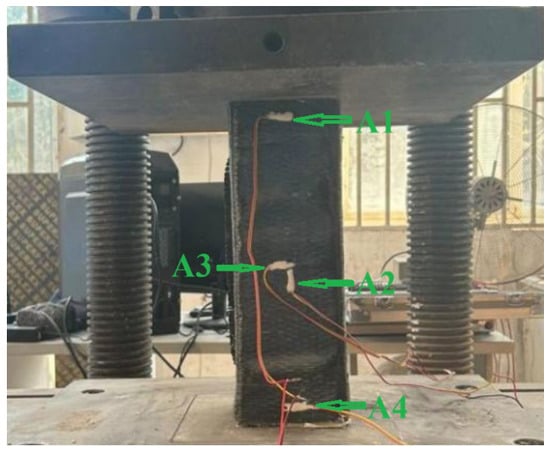
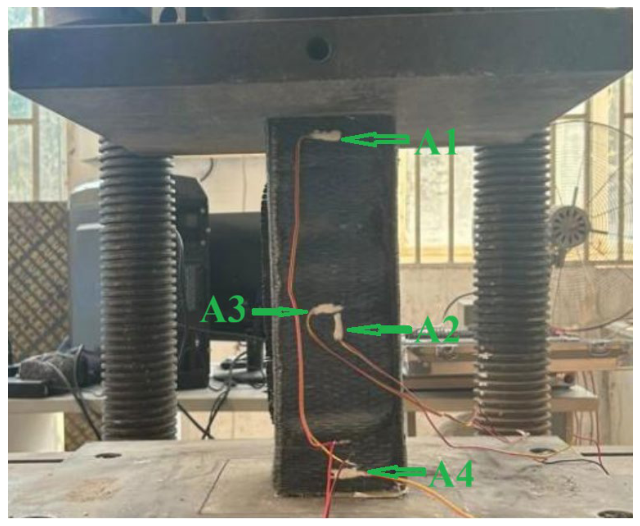
Axial compression tests were carried out on a 2000 kN long-column compression machine (Jinan Xinguang Testing Machine Manufacturing Co., Ltd., Jinan, China.)under monotonic loading. A constant displacement-controlled loading rate of 0.05 mm/min was applied throughout the test, corresponding to a strain rate of approximately 2.8 × 10⁻⁶ s−1 for the 300 mm high specimens. Strain gauges (model 120-15AA, gauge length 15 mm, China Jinzheng Electronic Technology Co., Ltd., Dongguan, China) were bonded at the mid-height of each specimen to capture both axial and hoop strains of the CFRP sheet. Load and displacement were recorded synchronously by the test machine, and strain signals were collected by a static strain acquisition instrument. The axial deformation used to construct the stress–strain curves was taken from the crosshead displacement of the testing machine, and the axial strain was calculated by dividing this displacement by the specimen height of 300 mm; the mid-height axial strain gauges were used to verify the initial elastic stage. The test was terminated when the CFRP sheet ruptured and the axial load dropped to approximately 70% of the peak load, or when the axial displacement reached 30 mm, whichever occurred first. The test setup and strain gauge layout are presented in Figure 4. In Figure 4, strain gauges 1–4 are designated A1–A4, respectively.
Figure 4.
Axial compression test setup and strain gauge arrangement.
3. Experimental Results
3.1. Failure Modes
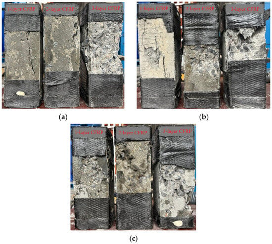
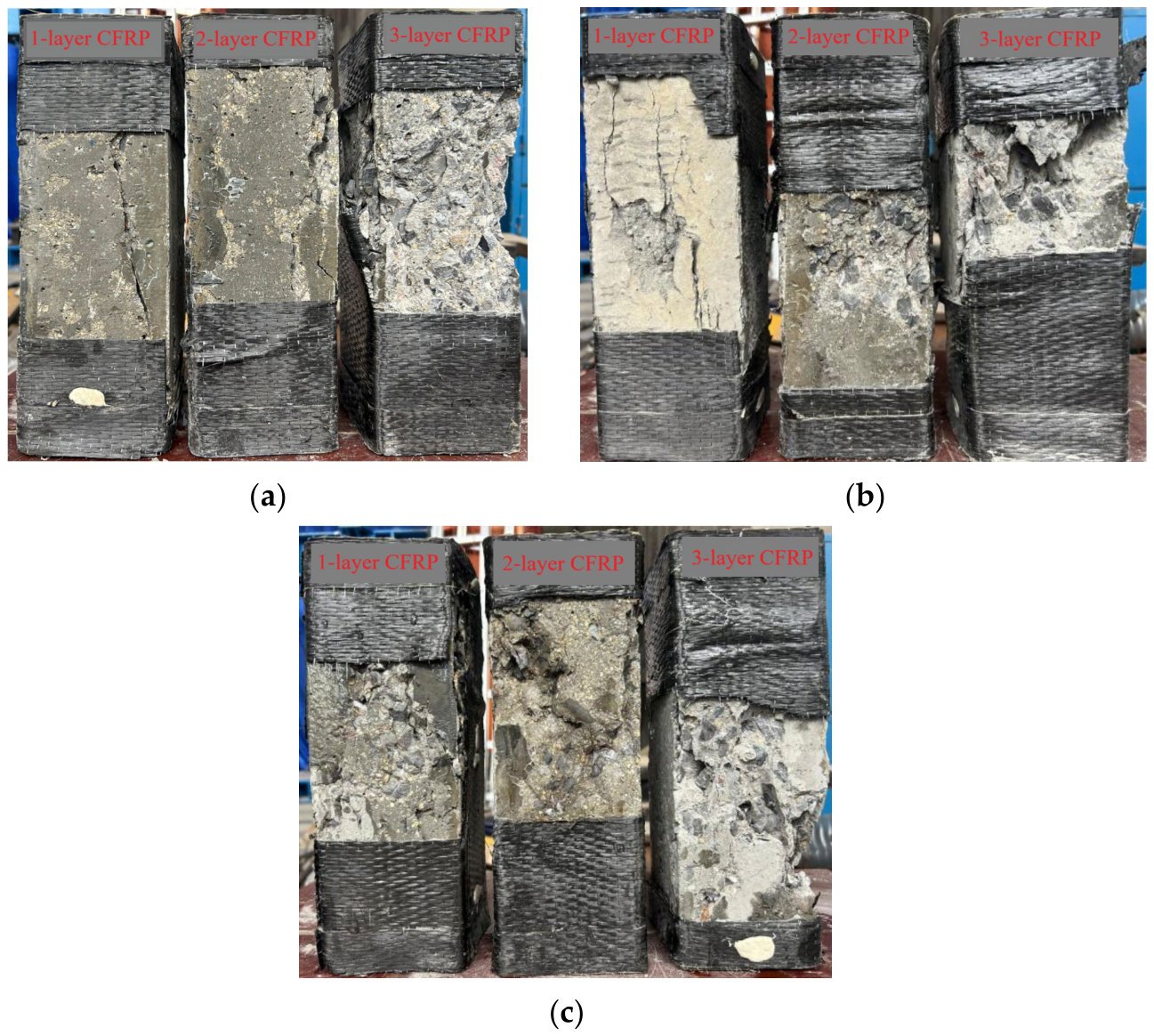
No obvious surface phenomenon was observed in the early loading stage. Near the ultimate load, audible fibre-fracture noise could be detected. After reaching the peak load, the CFRP sheet ruptured suddenly in the mid-height region, concrete debris was ejected, and the load dropped sharply, showing brittle failure controlled by CFRP rupture [15,19]. For 1-layer CFRP confinement, partial local cracking of the CFRP occurred; for 2-layer confinement, large-scale tearing was observed; for 3-layer confinement, extensive bursting rupture occurred. Higher CFRP stiffness accumulates more elastic strain energy released at failure, leading to more violent rupture. After the test, selected specimens were cut open to observe internal damage (Figure 5).
Figure 5.
Internal concrete damage after test for different RFA replacement ratios: (a) RFA0; (b) RFA50; (c) RFA100.
At an identical RFA replacement ratio, higher CFRP layers produced more severe internal concrete fragmentation: 1-layer confinement induced widespread cracking; 2-layer confinement caused partial spalling; 3-layer confinement led to massive concrete spalling. Under identical confinement, higher RFA replacement aggravated internal damage, attributed to more initial defects and weaker ITZ within RFA-incorporated concrete [20]. The hoop strain gauges were bonded at the mid-height of each face, as shown in Figure 4, to measure the average hoop strain of the CFRP sheet; they were not intended to capture the local strain at the corners. The initiation of CFRP rupture at or near the column corners was identified by post-test visual inspection of the rupture locations and the distribution of ejected concrete debris. This observation is consistent with corner stress concentration being a dominant trigger for premature CFRP failure in square sections [7,8], although the present strain measurements at the face centres cannot directly quantify the local corner strain.
3.2. Stress–Strain Relationships
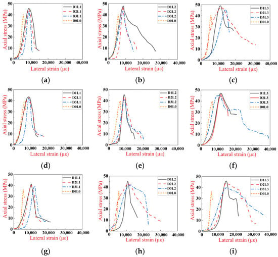
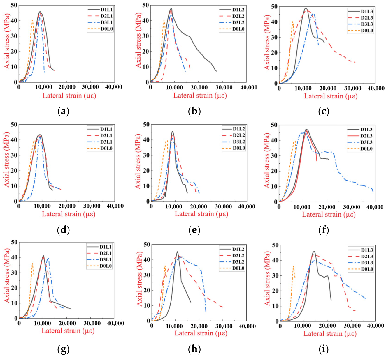
The axial stress–strain curves of the C50 series specimens are plotted in Figure 6. Two typical stages can be identified for CFRP-confined pre-damaged RAC: (1) Elastic stage-stress increases rapidly with limited axial strain; the CFRP confinement effect is not fully mobilised. (2) Confinement-softening stage-internal cracks propagate continuously, and CFRP hoop confinement is activated, which improves deformability and delays catastrophic failure [21,22]. Unconfined pre-damaged specimens showed nearly no descending branch, representing typical brittle behaviour. CFRP wrapping introduced an obvious post-peak softening segment and significantly enhanced ductility [4,17].
Figure 6.
Axial stress–strain curves of CFRP-confined pre-damaged RAC specimens: (a) RFA0-L1; (b) RFA0-L2; (c) RFA0-L3; (d) RFA50-L1; (e) RFA50-L2; (f) RFA50-L3; (g) RFA100-L1; (h) RFA100-L2; (i) RFA100-L3.
Higher CFRP layers improved specimen ductility. Increasing the RFA replacement ratio reduced peak strength yet enlarged peak strain and decreased the initial elastic modulus. More severe pre-damage reduced peak stress under identical confinement conditions.
3.3. Peak Strength
Key experimental results of all 27 specimens are summarised in Table 7. fcc and εcc denote the peak stress and peak strain of CFRP-confined pre-damaged specimens. εh,rup is the measured hoop rupture strain of the CFRP sheet. εfu is the ultimate tensile strain obtained from the CFRP coupon test. The strength ratio fcc/fco and strain ratio εcc/εco are also listed. Table 7 lists the complete specimen matrix for all 27 main specimens, covering all combinations of pre-damage level D1–D3, CFRP layer number L1–L3, and RFA ratio RFA0–RFA100.
Table 7.
Test results of CFRP-confined pre-damaged RAC specimens.
The peak stress fco and peak strain εco of the undamaged companion prisms used as normalization references were RFA0, fco = 40.2 MPa and εco = 5637 με; RFA50, fco = 39.5 MPa and εco = 6779 με; and RFA100, fco = 36.2 MPa and εco = 5629 με. These values were obtained from companion prism tests for each mix and were used to calculate the strength ratio fcc/fco and strain ratio εcc/εco in Table 7; they were not listed separately in the original table because the ratios were reported directly.
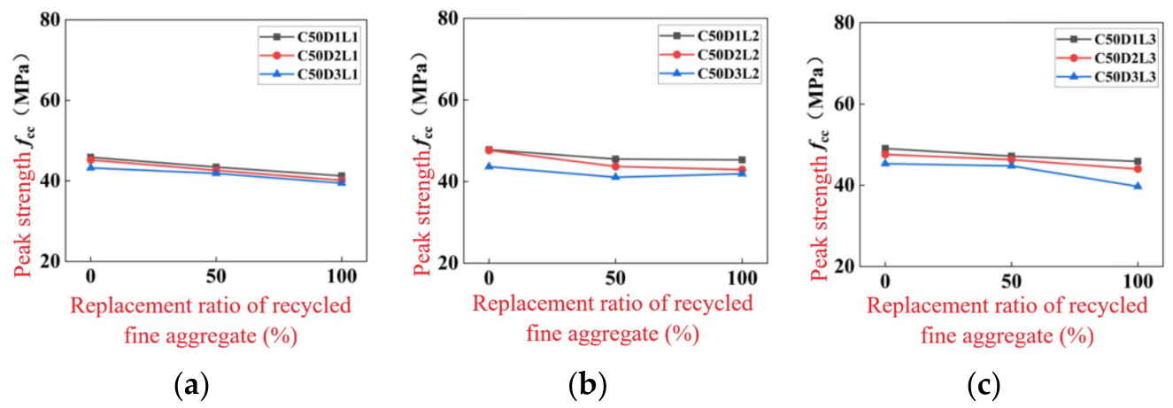
Because the 27 specimens correspond to 27 distinct combinations of pre-damage level, CFRP layer number and RFA ratio, no replicate specimens were available for each combination; therefore, ANOVA and interaction analysis were not performed. Instead, descriptive statistics were calculated for the main groups to support the observed trends. For peak strength fcc, the group means, standard deviations, coefficients of variation and 95% confidence intervals were: by pre-damage level, D1 = 45.71 MPa (SD = 2.33 MPa, COV = 5.1%, 95% CI = 43.92–47.50 MPa), D2 = 44.47 MPa (SD = 2.49 MPa, COV = 5.6%, 95% CI = 42.56–46.38 MPa), D3 = 42.34 MPa (SD = 2.07 MPa, COV = 4.9%, 95% CI = 40.75–43.93 MPa); by CFRP layer, L1 = 42.57 MPa (SD = 2.13 MPa, COV = 5.0%, 95% CI = 40.93–44.21 MPa), L2 = 44.41 MPa (SD = 2.35 MPa, COV = 5.3%, 95% CI = 42.60–46.22 MPa), L3 = 45.55 MPa (SD = 2.69 MPa, COV = 5.9%, 95% CI = 43.48–47.62 MPa); and by RFA content, RFA0 = 46.17 MPa (SD = 1.99 MPa, COV = 4.3%, 95% CI = 44.64–47.70 MPa), RFA50 = 44.06 MPa (SD = 2.07 MPa, COV = 4.7%, 95% CI = 42.47–45.65 MPa), RFA100 = 42.30 MPa (SD = 2.41 MPa, COV = 5.7%, 95% CI = 40.45–44.15 MPa). The 95% confidence intervals are descriptive intervals of the group means calculated using the t distribution with n = 9; they indicate the dispersion within each group and are not repeatability-based confidence intervals, because specimens within each group differ in the other two factors. These descriptive statistics are consistent with the trends discussed below; they are intended as indicative measures rather than formal significance tests. Higher pre-damage yielded lower peak strength. Under identical pre-damage and RFA ratio, increasing CFRP layers enhanced peak capacity (Figure 7).
Figure 7.
Variation of peak strength with RFA replacement ratio: (a) L1; (b) L2; (c) L3.
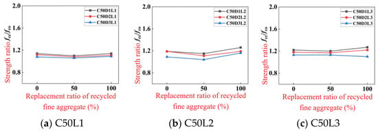
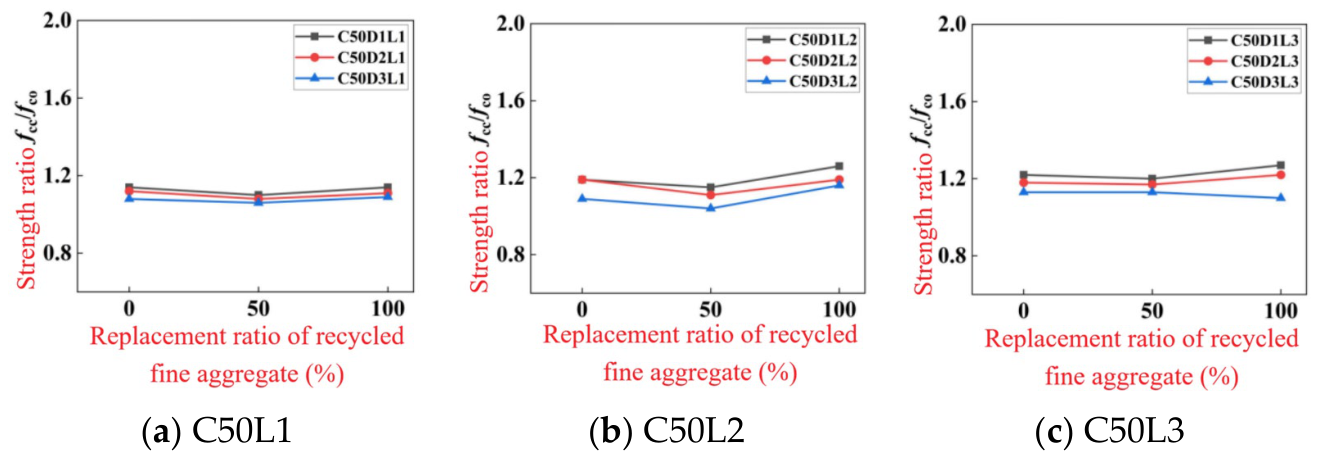
The strength ratio fcc/fco reflects the strength restoration effect by CFRP retrofitting (Figure 8). Most specimens had a strength ratio greater than 1, indicating that CFRP confinement can restore or even exceed the original compressive strength of pre-damaged RAC. Strength gain rose with increasing CFRP layers. An interesting observation is that the strength ratio dipped at RFA = 50% and rose again at RFA = 100%; this phenomenon is discussed in detail in Section 4.2.
Figure 8.
Strength ratio fcc/fco versus recycled fine-aggregate replacement ratio: (a) L1; (b) L2; (c) L3.
3.4. Peak Strain and CFRP Effective Rupture Strain
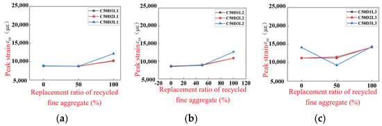
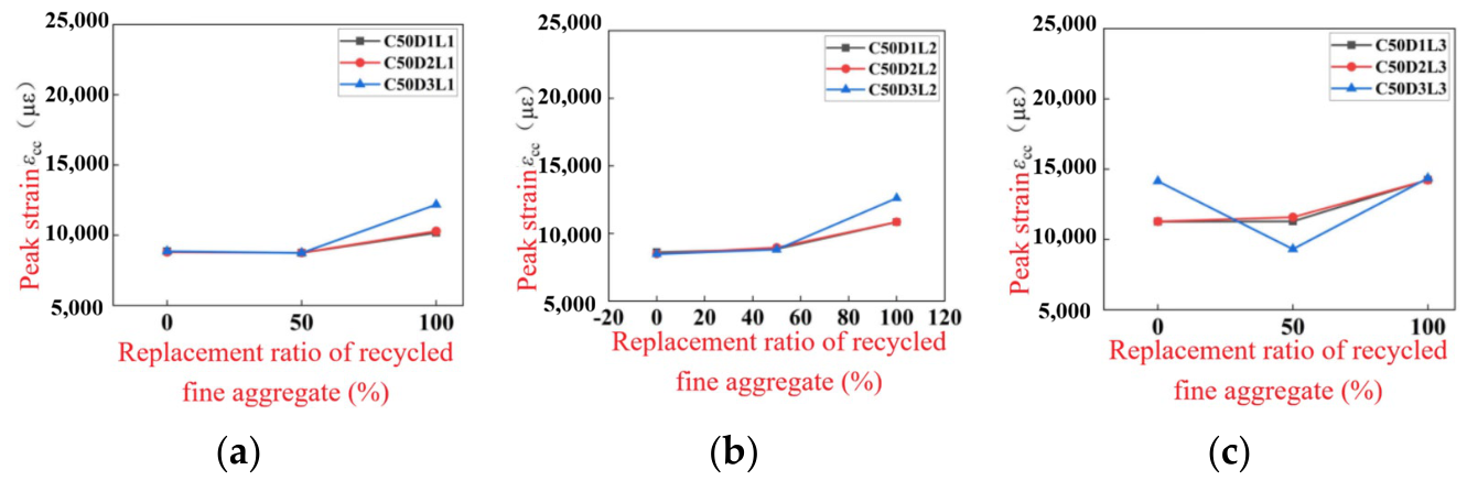
Peak strain represents deformability and ductility performance. The strain ratio εcc/εco is plotted in Figure 9. Generally, peak strain increased as RFA replacement grew. Higher pre-damage and more CFRP layers contributed to larger peak deformation.
Figure 9.
Strain ratio εcc/εco versus recycled fine-aggregate replacement ratio: (a) L1; (b) L2; (c) L3.
The effective hoop rupture-strain coefficient ke is defined as:
where εh,rup is the measured hoop rupture strain under the axial compression test, and εfu is the ultimate tensile strain from the CFRP coupon test. The average ke for all square specimens equals 0.60 ± 0.06 (range: 0.51–0.68). To verify whether pre-damage affects this coefficient, the mean and standard deviation of ke were calculated for each group: 0.636 ± 0.028 for D1, 0.569 ± 0.059 for D2, and 0.582 ± 0.063 for D3; 0.602 ± 0.058 for L1, 0.578 ± 0.060 for L2, and 0.607 ± 0.060 for L3; and 0.608 ± 0.061 for RFA0, 0.597 ± 0.048 for RFA50, and 0.582 ± 0.068 for RFA100. The group means vary only from 0.57 to 0.64, and the standard deviations are of the same order as the differences among groups, indicating no systematic trend with pre-damage level, CFRP layer number, or RFA content. Corner stress concentration of square cross-sections and non-uniform crack distribution make the CFRP sheet unable to fully utilise its material tensile capacity [7,8]. This coefficient is essential for modelling CFRP-confined square columns [15,19].
ke = εh,rup/εfu
4. Discussion
4.1. Comparison with Existing Published Data
The average effective rupture-strain coefficient ke = 0.60 ± 0.06 obtained in this work is consistent with the reported range of 0.50–0.65 for CFRP-confined square normal-aggregate concrete in the open literature [2,23]. For circular columns, ke is generally higher (0.65–0.80) due to uniform confining pressure without corner stress concentration [19]. For intact RAC square columns without pre-damage, existing papers reported ke near 0.55–0.62 [3,11]. This demonstrates that pre-damage does not significantly shift the averaged ke value for square specimens, because ke is primarily governed by section geometry and corner radius rather than the internal damage state of the concrete core [7].
Compared with available test data for pre-damaged normal concrete, pre-damaged RAC shows more obvious strength degradation under an identical pre-damage degree, due to the inferior ITZ performance of recycled aggregates [24,25]. The strength enhancement ratio fcc/fco in this study (1.04–1.27 for C50) is somewhat lower than that reported for CFRP-confined intact normal concrete square columns (typically 1.15–1.40 for equivalent confinement stiffness), which can be attributed to the combined effects of pre-damage and RAC defects [4].
4.2. Explanation for the Strength-Ratio Dip at 50% RFA Replacement
The strength ratio fcc/fco decreased at RFA = 50% and rebounded at RFA = 100%. Two possible reasons are discussed:
(1) Experimental scatter: RFA50 mixes contain both natural fine aggregate and RFA. The internal heterogeneity of the mixed-aggregate system is higher than that of the full-natural (RFA0) and full-recycled (RFA100) groups, which introduces certain test variability. The coefficient of variation for the RFA50 group (4.7%) is slightly larger than that for the RFA0 group (4.3%), but lower than that for the RFA100 group (5.7%). This indicates that the highest test variability actually occurs in the full-recycled RFA100 group.
(2) Material-level mechanism: partial replacement generates more complex multi-phase ITZs between natural and recycled interfaces. At 100% RFA, the matrix forms a relatively unified recycled-aggregate-based system, mitigating part of the interfacial mismatch effect. A similar non-monotonic trend has been reported in several RAC material studies [17,20].
It should be emphasised that this non-monotonic behaviour is observed only in the strength ratio (fcc/fco), not in the absolute peak strength (fcc), which decreases monotonically with RFA replacement. The dip in the ratio is partly because fco (the denominator) also decreases with RFA content. This phenomenon should not be generalised as a universal mechanistic rule; more replicate specimens and microstructural investigations are needed in future studies.
4.3. Effect of Repair Mortar for D3 Severely Damaged Specimens
Repair mortar was only applied to spalled surface layers rather than the entire cross-section. The core concrete still retains pre-induced distributed microcracks. The repair mortar mainly recovers geometric integrity and provides a smooth bonding surface for CFRP application, rather than contributing to bulk compressive resistance. Based on the measured mortar strength (≈45 MPa) and the estimated repaired area fraction (<5% of the gross cross-section), the contribution of repair mortar to the overall axial strength is estimated to be less than 3%. Therefore, the mortar contribution cannot eliminate the pre-damage effect inside the concrete core. The test conclusions are applicable to the scenario where only local surface spalling occurs and the core concrete retains pre-damage cracks; for cases with large-area cross-section damage, the results may not directly apply [10,13].
To distinguish the relative contributions of pre-damage, repair mortar, and CFRP confinement, a descriptive sensitivity analysis was performed using the group means reported in Section 3.3. Because the 27 specimens correspond to 27 distinct parameter combinations and no replicate specimens were available, a formal variance decomposition or factorial sensitivity analysis was not possible; the following comparison is therefore indicative rather than a strict statistical separation. For peak strength, increasing the pre-damage level from D1 to D3 reduced the group mean from 45.71 MPa to 42.34 MPa, a decrease of 3.37 MPa or about 7.4%. Increasing the CFRP layer number from L1 to L3 increased the group mean from 42.57 MPa to 45.55 MPa, an increase of 2.98 MPa or about 7.0%. Increasing the RFA replacement ratio from RFA0 to RFA100 reduced the group mean from 46.17 MPa to 42.30 MPa, a decrease of 3.87 MPa or about 8.4%. The estimated contribution of the repair mortar is less than 3%, as given above. On this descriptive basis, the effects of pre-damage and RFA replacement on peak strength are comparable and somewhat larger than the effect of CFRP layer number, while the repair mortar contribution is the smallest. These comparisons are consistent with the discussion in Section 4.1 and Section 4.2 and should not be interpreted as independent effect sizes, because each group mean still contains variations in the other two factors.
The repair interface may influence local stress transfer and CFRP rupture in two ways. First, the repair mortar has a measured compressive strength of about 45 MPa, which is comparable to the RAC substrate, but its elastic modulus and interface bond with the old concrete may differ from those of the substrate. This can produce a local stiffness mismatch and stress redistribution near the repaired zone. Second, because the repaired area is limited to local surface spalling (≤5% of the gross cross-section), the overall axial load transfer is still dominated by the concrete core and the CFRP jacket. The interface is therefore expected to affect local strain concentrations rather than the global peak strength. CFRP rupture in the present tests was observed at or near the column corners rather than exclusively at the repaired zones, which is consistent with corner stress concentration being the dominant trigger for premature rupture in square sections [7,8]. Nevertheless, a repaired interface with weak bond or high porosity could initiate local debonding and accelerate CFRP rupture in severely damaged specimens; this possibility cannot be excluded from the present macroscopic observations and should be examined in future work with interface-level instrumentation or microstructural characterisation.
4.4. Size-Efect Consideration
The specimen cross-section is 100 mm square. For real-world larger-scale columns, the size effect will reduce the nominal compressive strength and change the CFRP utilisation ratio. Existing studies on size effects in CFRP-confined concrete indicate that larger specimens tend to exhibit lower strength enhancement ratios and lower ke values due to the more pronounced corner stress concentration and larger fracture process zone [8,19]. Caution should be exercised when directly extrapolating the present test results to full-scale components. Further large-scale tests are needed to quantify the size-effect influence and establish appropriate scaling factors.
4.5. Empirical Prediction Equations for Peak Strength and Peak Strain
Based on the present experimental database of 27 C50 specimens, multivariate regression was performed. Three dimensionless influencing factors were defined:
- •
- Pre-damage factor λd: D1 = 0, D2 = 0.5, D3 = 1.0 (normalised damage severity);
- •
- CFRP layer factor λcfrp: L1 = 1, L2 = 2, L3 = 3 (number of CFRP layers; this is a discrete ordinal coding used for regression, not a physical confinement stiffness ratio);
- •
- RFA replacement factor λrfa: RFA0 = 0, RFA50 = 0.5, RFA100 = 1.0.
The physical confinement ratio fl/fco was not directly used because the actual lateral confinement pressure varies with corner radius and hoop rupture strain; the layer number is therefore used only as a simple ordinal variable.
The proposed empirical formulas for CFRP-confined pre-damaged RAC square columns are:
fcc/fco = 1.065 + 0.063·λcfrp − 0.072·λd + 0.018·λrfa
εcc/εco = 0.982 + 0.345·λcfrp + 0.218·λd + 0.486·λrfa
The predicted values were compared with the experimental measurements. For the strength ratio, the coefficient of determination is R2 = 0.47, and the mean absolute percentage error (MAPE) is 4.2%; for the strain ratio, R2 ≈ 0 and MAPE is 8.7%. These values indicate that the strength equation (Equation (2)) captures part of the experimental scatter, whereas the strain-ratio equation (Equation (3)) has no predictive capability (R2 = 0). Both equations should be regarded as preliminary empirical correlations rather than validated predictive models. Because the same 27 data points were used for both fitting and comparison, this comparison does not constitute independent validation. It should be noted that these formulas are purely empirical statistical fits based on the current C50 test database and are not mechanics-based models [21]. They are applicable only within the parameter range of this study: C50 concrete, RCA = 50%, 100 mm square columns, 1–3 CFRP layers, and RFA = 0–100%. Direct extrapolation to other concrete strengths, section sizes, or confinement levels is not recommended [22]. A preliminary comparison with the classic Mander model [21] suggested that it may overestimate the strength of pre-damaged RAC square columns because it was developed for steel-confined concrete and does not account for pre-damage degradation or recycled-aggregate ITZ weakening; however, a detailed quantitative comparison is beyond the scope of this empirical study and is not presented here.
4.6. Limitations of This Study
The following limitations should be acknowledged:
(1) Only one concrete strength grade (C50) was investigated; the applicability to other strength grades requires further validation.
(2) Only monotonic axial compression was considered; seismic-type cyclic loading was not addressed [12,23,26,27,28]. Therefore, the present results describe material-level axial compression behaviour and cannot be directly used to quantify the seismic performance, hysteretic response, or energy dissipation of structural columns.
(3) The specimen size was limited to 100 mm square columns; size effects on full-scale members were not quantified [19]. The small-scale specimens also mean that the measured strength enhancement and rupture strain should not be directly extrapolated to full-scale structural members without scaling verification.
(4) No microstructural characterisation (e.g., SEM, porosity measurement) was performed; the mechanistic explanations are based on macroscopic observations and existing literature.
(5) Environmental factors such as freeze–thaw, chloride ingress, and long-term creep were not considered.
(6) The empirical formulas are data-driven and limited to the tested parameter range; a mechanics-based constitutive model remains to be developed [22].
(7) Quantitative residual stiffness and residual deformation after pre-damage were not measured, because reloading to obtain these indices would alter the pre-damage state and introduce secondary disturbance before CFRP wrapping; future work should incorporate such damage indices for constitutive modelling.
(8) The findings are limited to material-level axial compression of small-scale square columns with local surface spalling and pre-existing cracks. They demonstrate the feasibility of CFRP confinement for restoring axial capacity and deformability, but they do not constitute a structural seismic design method. Seismic retrofitting design requires additional cyclic loading tests, large-scale member tests, reinforcement detailing considerations, and frame-level response analysis.
5. Conclusions
Within the scope of the present experimental programme, the following conclusions can be drawn:
(1) CFRP hoop confinement can effectively restore and improve both compressive strength and deformability for pre-damaged RAC square columns. CFRP wrapping is a feasible retrofitting solution for pre-damaged RAC members.
(2) Severe initial pre-damage exerts a negative influence on post-strengthening performance: under identical CFRP confinement and RFA ratio, a higher damage level reduces peak strength.
(3) Increasing the recycled fine-aggregate replacement ratio reduces the absolute peak strength of CFRP-confined pre-damaged RAC, while peak strain and ductility are generally improved. Engineering application should balance strength loss and ductility benefit when adopting high-content RFA. The observed non-monotonic dip in the strength ratio at 50% RFA should not be generalised without further validation.
(4) Increasing CFRP wrapping layers enhances both peak strength and peak deformation capacity. More strain energy is released upon failure, resulting in more violent CFRP rupture and severe internal concrete fragmentation.
(5) For square-section specimens under axial compression, the average CFRP effective hoop rupture-strain coefficient is 0.60 ± 0.06 (range 0.51–0.68). This reduction factor should be adopted when establishing constitutive models for CFRP-confined pre-damaged RAC square columns.
(6) Empirical prediction formulas for peak strength and peak strain are proposed based on the test data, with MAPE of 4.2% and 8.7%, respectively. While the strength equation provides a preliminary reference for retrofitting design within the tested parameter range, the strain-ratio equation has negligible predictive capability (R2 = 0) and should only be used for qualitative trend description. Further large-scale and multi-strength-grade tests are required to generalise the findings.
Author Contributions
J.Y.: data curation, formal analysis, investigation, methodology, funding acquisition, project administration, and writing—original draft; J.A.: formal analysis, data curation, investigation, methodology; F.H.: formal analysis and writing—review and editing; S.P.: writing—review and editing. All authors have read and agreed to the published version of the manuscript.
Funding
This research is funded by the “Key R&D Program Projects in Hubei Province of China” (Grant No. 2025BCB105) and the “Construction Science and Technology Program of Hubei Province” (Grant No. JK2025056), and their support is gratefully acknowledged.
Data Availability Statement
Some or all data, models, or code that support the findings of this study are available from the corresponding author upon reasonable request.
Acknowledgments
The authors would like to thank Ying Peng from Wuhan Bohong Construction Group Co., Ltd. for his assistance with the investigation and for providing financial support for this research, as well as for his valuable guidance on the feasibility of the research direction.
Conflicts of Interest
Authors Jun Yan and Junjie An were employed by the company Wuhan Bohong Construction Group Co., Ltd. The remaining authors declare that the research was conducted in the absence of any commercial or financial relationships that could be construed as a potential conflict of interest.
References
- Antunes, A.; Costa, H.; Carmo, R.D.; Júlio, E. A comprehensive review of sustainable use of construction and demolition waste as recycled aggregates in the production of concrete-Properties, mix design and on-site applications. Constr. Build. Mater. 2025, 482, 141733. [Google Scholar] [CrossRef] [Scilit]
- Xiao, J.Z.; Li, J.B.; Zhang, C. Mechanical properties of recycled aggregate concrete under uniaxial loading. Cem. Concr. Res. 2005, 35, 1187–1194. [Google Scholar] [CrossRef] [Scilit]
- Zeng, J.J.; Zhang, X.W.; Chen, G.M.; Wang, X.-M.; Jiang, T. FRP-confined recycled glass aggregate concrete: Concept and axial compressive behavior. Constr. Build. Mater. 2020, 30, 101288. [Google Scholar] [CrossRef] [Scilit]
- Chen, G.M.; He, Y.H.; Jiang, T.; Lin, C. Behavior of CFRP-confined recycled aggregate concrete under axial compression. Constr. Build. Mater. 2016, 111, 85–97. [Google Scholar] [CrossRef] [Scilit]
- Lai, M.H.; Peng, W.J.; Xie, Y.M.; Lin, C. Stress-strain behavior of CFRP-confined recycled fine aggregate concrete: A packing-coupling approach. Structures 2026, 87, 111734. [Google Scholar] [CrossRef] [Scilit]
- Wang, J.; Lin, S.Q.; Zhao, Y.G. Stress path-based compressive strength model of FRP-confined recycled aggregate concrete. Constr. Build. Mater. 2024, 440, 137437. [Google Scholar] [CrossRef] [Scilit]
- Wu, L.M.; Wu, Y.F. Effect of corner radius on the performance of CFRP-confined square concrete columns: Test. Eng. Struct. 2008, 32, 493–505. [Google Scholar] [CrossRef] [Scilit]
- Azhagarsamy, S.; Pannirselvam, N.; Vanjinathan, J.; Sundararaman, S.; Premkumar, R. Effect of cross-sectional corner radius on the compressive behavior of GFRP-confined concrete prisms under repetitive loading: Experimental study and ANN-RSM modeling. Case Stud. Constr. Mater. 2025, 23, e05305. [Google Scholar] [CrossRef] [Scilit]
- Hammad, M.; Bahrami, A.; Khokhar, S.A.; Khushnood, R.A. A State-of-the-Art Review on Structural Strengthening Techniques with FRPs: Effectiveness, Shortcomings, and Future Research Directions. Materials 2024, 17, 1408. [Google Scholar] [CrossRef] [Scilit] [PubMed]
- Pellegrino, C.; Modena, C. Analytical model for FRP confinement of concrete columns with and without internal steel reinforcement. J. Compos. Constr. ASCE 2010, 14, 693–705. [Google Scholar] [CrossRef] [Scilit]
- Xu, Y.; Wang, X.; Dong, J.F.; Guan, Z.; Wang, Q. Experimental and numerical study on the compressive behaviour of CFRP-confined columns with recycled aggregate concrete. Constr. Build. Mater. 2025, 461, 139916. [Google Scholar] [CrossRef] [Scilit]
- Song, S.; Tian, Z.; Zhao, Z.Y.; Li, X.; Zhao, J.; Xu, B. Experimental study on seismic performance of CFRP-strengthened recycled concrete columns with different levels of seismic damage. Buildings 2023, 13, 1470. [Google Scholar] [CrossRef] [Scilit]
- GB 50367-2013; Code for Design of Strengthening Concrete Structure with Fiber Reinforced Polymer. China Architecture & Building Press: Beijing, China, 2013. (In Chinese)
- ACI Committee 440. Guide for the Design and Construction of Externally Bonded FRP Systems for Strengthening Concrete Structures (ACI 440.2R-17); American Concrete Institute: Farmington Hills, MI, USA, 2017. [Google Scholar]
- Lam, L.; Teng, J.G. Strength models for fiber-reinforced plastic-confined concrete. J. Struct. Eng. ASCE 2002, 128, 612–623. [Google Scholar] [CrossRef] [Scilit]
- Etxeberria, M.; Marí, A.R.; Vázquez, E. Recycled aggregate concrete as structural material. Mater. Struct. 2007, 40, 529–541. [Google Scholar] [CrossRef] [Scilit]
- Tabsh, S.W.; Abdelfatah, A.S. Influence of recycled concrete aggregates on strength properties of concrete. Constr. Build. Mater. 2009, 23, 1163–1167. [Google Scholar] [CrossRef] [Scilit]
- Tanish, D.; Chandra, S.D.; Naval, M. Behaviour of confined recycled aggregate concrete under compressive loading: An experimental investigation. J. Build. Eng. 2020, 32, 101825. [Google Scholar] [CrossRef] [Scilit]
- Ozbakkaloglu, T.; Lim, J.C.; Vincent, T. FRP-confined concrete in circular sections: Review and assessment of stress-strain models. Eng. Struct. 2013, 49, 1068–1088. [Google Scholar] [CrossRef] [Scilit]
- Öz Ali Yılmaz, M.K.; Benli, A.; Kaplan, G. Sustainable prepacked alkali-activated concrete: Influence of natural zeolite, recycled aggregate, and curing conditions on mechanical, durability, and thermal performance. Arch. Civ. Mech. Eng. 2025, 25, 5–6. [Google Scholar] [CrossRef] [Scilit]
- Mander, J.B.; Priestley, M.J.N.; Park, R. Theoretical stress-strain model for confined concrete. J. Struct. Eng. ASCE 1988, 114, 1804–1826. [Google Scholar] [CrossRef] [Scilit]
- Teng, J.G.; Huang, Y.; Lam, L.; Ye, L.P. Theoretical model for fiber-reinforced polymer-confined concrete. J. Compos. Constr. ASCE 2007, 11, 201–210. [Google Scholar] [CrossRef] [Scilit]
- Manan, A.; Zhang, P.; Chen, W.Y.; Alattyih, W.; Ahmad, J.; Umar, M. CAI-based constitutive model simulator for predicting the axial load-deflection behavior of recycled concrete powder and steel fiber reinforced concrete column. Constr. Build. Mater. 2025, 470, 140628. [Google Scholar] [CrossRef] [Scilit]
- Zhao, D.; Zhang, J.W.; Wang, F.; Liang, H. Experimental and theoretical analysis on seismic performance of reinforced recycled brick-concrete aggregate concrete columns. Structures 2026, 88, 111906. [Google Scholar] [CrossRef] [Scilit]
- Lin, W.W.; Zhou, Y.W.; Xing, F.; Zhuang, J.; Huang, X. Flexural performance and design of carbonated recycled aggregate concrete beams based on tests and simulations. Constr. Build. Mater. 2025, 501, 144296. [Google Scholar] [CrossRef] [Scilit]
- Islam, M.J.; Shahjalal, M.; Muniruzzaman, M.; Bachu, H.A.E.; Miah, A. Behavior of recycled brick aggregate concrete column retrofitting with carbon fiber reinforced polymer under concentric and eccentric loading. Thin-Walled Struct. 2025, 216, 113763. [Google Scholar] [CrossRef] [Scilit]
- Shen, Z.H.; Qiu, T.; Guo, Z.Q.; Yuan, M.; Meng, F. Seismic performance of high ductile FRP-confined concrete columns: Experimental and numerical investigation. Constr. Build. Mater. 2026, 532, 146725. [Google Scholar] [CrossRef] [Scilit]
- Abokwiek, R.; Abdalla, J.A.; Hawileh, R.A.; El Maaddawy, T. Behavior of reinforced concrete columns strengthened with hybrid NSM-CFRP strips and CFRP wraps under axial compression and biaxial bending. Structures 2026, 85, 111191. [Google Scholar] [CrossRef] [Scilit]

Disclaimer/Publisher’s Note: The statements, opinions and data contained in all publications are solely those of the individual author(s) and contributor(s) and not of MDPI and/or the editor(s). MDPI and/or the editor(s) disclaim responsibility for any injury to people or property resulting from any ideas, methods, instructions or products referred to in the content. |
© 2026 by the authors. Licensee MDPI, Basel, Switzerland. This article is an open access article distributed under the terms and conditions of the Creative Commons Attribution (CC BY) license.