


Abstract
Nowadays various coupling strategies have been developed to combine the strengths of different numerical methods in computational fluid dynamics (CFD), among which the coupled algorithm of the lattice Boltzmann-finite volume method (LBM-FVM) has gained widespread attention. However, research on parallel optimization of LBM-FVM coupled solvers remains limited, mostly focused on independent solvers. In this work, we proposed a flexible framework and optimization schemes to explore the coordinated balance of accuracy-efficiency-hardware adaptability. First, we designed a processor layout strategy to address load imbalance and communication redundancy in the coupled solver. We then developed several parallelization techniques, including LBM restructuring, data reuse, and SIMD optimization for targeted kernels on the most advanced architecture of the Sunway series in China, namely SW26010P heterogeneous many-core processors, which provide hardware architectural advantages well suited for large-scale parallel computational fluid dynamics. Finally, the accuracy of the LBM-FVM coupling simulations was validated through benchmark simulations of 2D/3D lid-driven cavity flow. The results show that our LBM-FVM coupling solver can accurately capture flow characteristics, with vortex structures consistent with experimental data. Additionally, we achieved a 152× speedup for the LBM solver and a 126× speedup for the coupled simulation compared to the standalone FVM simulation on the New Sunway supercomputer system. Our approach marks a milestone in the field of LBM implementations and provides a promising future for coupled algorithms in CFD.
1. Introduction
Numerical coupling algorithms have been increasingly applied in fields such as multi-scale simulation and heat transfer. As the demand for higher computational accuracy and efficiency continues to grow, it is necessary to adopt differentiated modeling strategies for different regions to achieve more precise physical process descriptions. These algorithms typically require high spatial and temporal resolutions, which in turn significantly increase computational costs under the same physical scale. Therefore, developing highly efficient and scalable numerical coupling frameworks that can fully leverage the advantages of supercomputing architectures has become an essential task in industrial applications.
Nowadays, various coupling strategies have been developed to employ the most suitable numerical method in each computational region and obtain the global solution through interface information exchange. For example, the MD-FVM [1] hybrid method links the microscopic interfacial mechanisms revealed by molecular dynamics simulations with the macroscopic flow and temperature fields described by the finite volume method, providing a key multiscale simulation approach for investigating phenomena such as thermal convection at the nanoscale. The MD-LBM [2] coupled algorithm achieves over a 90% improvement in computational efficiency while preserving consistency with pure molecular dynamics results, showing strong potential for studying complex multiscale phenomena with dynamic coupling across multiple scales. The DSMC-FVM [3] coupled algorithm performs effectively in handling rotating flows with multiple components and non-uniform mass fraction distributions, significantly reducing computational cost and demonstrating strong potential for applications in complex flow problems. Among various coupling algorithms, the LBM-FVM coupling integrates macroscopic continuum fields with microscopic particle dynamics, enabling efficient cross-scale simulations. This coupling strategy has demonstrated good applicability in engineering numerical simulations. Existing studies have applied it to the numerical solution of coupled radiation-convection heat transfer in complex geometries, as well as to the development of hybrid solvers for two-phase flows [4,5]. These problems are characterized by multiscale transport processes and geometric complexity.
While great advantages are expected for LBM-FVM coupling simulations in multiscale and multi-domain coupled simulations, the parallel optimization of LBM-FVM coupled simulations faces challenges in multiple aspects. On one hand, LBM and FVM exhibit inconsistencies in mathematical modeling, discretization schemes, and boundary condition handling, leading to highly complex communication between individual computational modules as well as between the core software and its supporting tools. This necessitates the establishment of unified, standardized data interfaces to enhance the software’s maintainability and robustness. On the other hand, the computational characteristics of LBM and FVM differ significantly: LBM inherently possesses data parallelism but is sensitive to memory bandwidth, whereas FVM relies on the exchange of neighboring information in control volumes and features a higher computation-to-memory access ratio. Traditional single-core or small-scale parallel architectures struggle to simultaneously meet the computing power requirements of both methods, resulting in increasingly prominent efficiency bottlenecks in coupled simulations.
Meanwhile, the architecture of supercomputers has undergone a subtle yet distinct shift, gradually transitioning from homogeneous systems to heterogeneous systems. Within heterogeneous architectures, coprocessors or accelerators contribute approximately 90% of the total computing potential; therefore, fully leveraging the computing performance of slave cores is crucial for improving computational efficiency. However, the inherent collaborative parallelism of LBM-FVM coupled simulations imposes unique demands on hardware resource scheduling, which specifically requires addressing three critical issues: (1) load balancing of computational tasks between LBM and FVM; (2) latency control in cross-method data communication; and (3) memory access optimization under heterogeneous architectures. Currently, research on the parallelization of coupled simulations predominantly focuses on individual methods, with no systematic design yet established for the collaborative parallelism of coupled algorithms. Furthermore, during many-core acceleration, mismatches frequently arise between the computational characteristics of the two methods and the hardware architecture, which not only leads to low utilization of hardware computing power but also impedes the full release of the performance potential of many-core hardware.
To address the aforementioned challenges, we target the optimization of our self-developed LBM-FVM coupled solver on the New Sunway supercomputer. By fully exploiting the advantages and high parallelism of this many-core system, we aim to construct a flexible and highly parallelizable CFD numerical computation method. The major contributions of our study include:
(1) We exploit a flexible framework with integrated architecture. In our framework, the two numerical approaches can be individually adopted or coupled, and different region data can be converted, interpolated, and reconstructed at the interfaces to obtain the entire full solution.
(2) We implement a dynamic parallelization mapping strategy to balance the computations and communication between LBM and FVM subdomains.
(3) We propose a multilevel parallelization scheme and SIMD acceleration closely combined with the underlying hardware on the New Sunway system for LBM.
To assess the efficiency of our implementation, we tested our optimization of LBM and coupling simulations on the Chinese New Sunway supercomputer system. The results demonstrated a maximum speedup of 152× for LBM-LES and a maximum speedup of 126× for the coupling simulation compared to the single FVM simulation.
2. Related Works
2.1. The Current State of LBM-FVM Coupling
The coupling of the FVM and LBM combines the efficiency of FVM in solving macroscopic continuum equations with the capability of LBM to capture mesoscopic physical mechanisms, providing a powerful numerical tool for investigating complex flow problems. Xu et al. [6,7,8] derived a distribution function reconstruction algorithm and established an analytical relationship between macroscopic variables and mesoscopic variables in LBM.
Subsequently, following the idea of partitioned coupling, He and Tao [9] developed the CFVLBM numerical coupling code and conducted multi-scale simulation cases on six heat transfer and fluid flow problems. The study found that for multi-scale processes, the “partitioned solution with interface coupling” method converges several orders of magnitude faster than using a unified mesoscopic or microscopic numerical method to solve the entire computational domain. Luan et al. [10] verified the correctness of the coupled simulation and conducted thermal convection analysis based on the two-dimensional lid-driven cavity flow. Chen et al. [11,12] also reported their work on distribution function reconstruction. Tong et al. [13] reviewed multi-scale methods used to couple particle-based mesoscopic methods.
In 2012, Xu et al. [8] extended the experience from two-dimensional simulations to three dimensions and performed thermal convection simulations for three-dimensional lid-driven cavity flows. Luan et al. [14] systematically studied the performance of the coupling scheme between FVM and LBM through three cases. The test results showed that CFVLBM has higher efficiency than the multi-block LBM. Li et al. [15] proposed an LBM-FVM coupling algorithm for fluid flow and heat transfer at full-domain. In their method, LBM is applied to solve natural convection and heat transfer, and FVM is responsible for velocity. A variety of FVM-LBM coupling strategies have been proposed, each designed to address particular challenges in fluid dynamics simulations. However, most existing studies focus on distribution function reconstruction and validation under low-Reynolds-number conditions, while parallel implementations of coupled algorithms remain limited, with the majority of efforts concentrated on accelerating the individual methods. Zou et al. [16] investigated the techniques of LBM-FVM coupling for viscoelastic flows and conducted a theoretical analysis on homogeneous acceleration. Zhou et al. [17] mainly focused on parallel acceleration under homogeneous computing environments and low-Reynolds-number conditions.
In the LBM-FVM coupling framework, distribution function reconstruction is a critical step. As a mesoscopic numerical method, LBM exhibits inherent information incompleteness when particle distribution functions are reconstructed from macroscopic variables. Xu et al. [8] investigated the effects of grid resolution and Reynolds number on the L2/L-inf norms in the reconstruction process, while Latt et al. [18] examined the stability and Reynolds number applicability of different distribution function reconstruction operators, showing that the second-order nonlinear reconstruction operator achieves the highest accuracy at high Reynolds numbers. In the present study, the nonlinear distribution function reconstruction operator in the aforementioned work is adopted, and the reconstruction formula is given as follows:
In summary, the coupling of FVM and LBM has become a key pathway to overcoming the limitations of single methods and achieving high-resolution simulations of complex interacting physical processes. However, research on parallel computing for such coupled algorithms remains limited, leaving significant opportunities for further investigation.
2.2. Advances in Parallel Acceleration for CFD
With the increasing demand for high-precision simulations in industry, CFD faces rapidly growing grid sizes and model complexity, posing significant computational challenges. To address these challenges, parallel computing has evolved from early CPU-cluster MPI implementations based on grid partitioning for load balancing to modern multi-core and heterogeneous architectures [19] that achieve further acceleration through optimized load distribution and communication overlap [20]. Building on these advances, the computational requirements of CFD continue to grow with the increasing complexity of CFD problems. For example, in high-Reynolds-number ship hydrodynamics simulations, the RANS/DES turbulence models require grid sizes ranging from millions [21] to tens of millions [22] for model-scale simulations and from tens of millions to hundreds of millions for full-scale ship simulations [23]. Compared with RANS, LES demands substantially higher grid resolution. In high-fidelity simulations of complex high-Reynolds-number flows, studies have reported problem sizes of approximately ten billion degrees of freedom, illustrating the massive grid requirements of LES [24,25]. The exorbitant computational cost of DNS stems from its extremely high-resolution requirements. The number of grid points needed for full-scale ship simulation is extremely high, making it unfeasible both currently and for the foreseeable future [23].
Significant breakthroughs have been achieved in the parallel acceleration of FVM across CPU, GPU, and heterogeneous architectures. On the CPU side, high efficiency and scalability have been realized through hybrid parallelization and architecture optimization. For example, Afzal et al. [26] achieved a 1.8× speedup on multi-core CPUs using OpenMP with the RBSOR scheme for FVM-based flow simulations on grids up to 40,804 cells. In GPU acceleration, Wang et al. [27], based on the Kokkos framework, obtained speedups exceeding 400× on hardware such as RTX 4090 and A100, and Afzal et al. [26] achieved a speedup of approximately 200× on 2048 CUDA cores. In heterogeneous computing, Xue et al. [28] proposed a cooperative computing strategy for FVM solvers that dynamically distributes the workload between CPU and GPU based on a performance model. On million-cell grids, it achieved up to 1.18× speedup, markedly surpassing pure GPU performance. These results demonstrate the outstanding performance and scalability of FVM on heterogeneous supercomputing platforms.
The parallel development of LBM has followed a clear technological trajectory from CPU to GPU and then to heterogeneous co-processing. Early studies achieved notable results on CPU clusters using MPI + OpenMP hybrid programming. For instance, Körner et al. [29] achieved near-linear strong scaling on 64 cores. In addition, Schornbaum and Rüde [30] completed simulations on 886 billion grid points with nearly 2 million threads, reaching a peak performance of 889,602 MLUPS. During the GPU acceleration stage, Meng et al. [31] performed full-process GPU parallelization of an improved LBM, achieving a maximum speedup of 92.96× on a problem with 33,000 grid nodes. In the heterogeneous computing stage, Tao et al. [32] implemented large-scale LBM simulations on the “Dongfang” supercomputer using MPI, OpenMP, Pthreads, and OpenCL. By employing dynamic task partitioning and load-balancing strategies, they enabled coordinated CPU-DCU execution, achieving up to 4× performance improvement over the unoptimized case in simulations with grids on the order of one billion and a 20× speedup compared with 32-core CPU-only computations. Kummerländer et al. [33] also realized cooperative LBM computations on CPU-GPU heterogeneous systems. Their numerical experiments, covering grids from one million to several hundred million nodes, demonstrated performance improvements of up to 87% relative to traditional GPU-only approaches.
Overall, the parallel acceleration performance of LBM is significantly superior to that of FVM. Existing studies on acceleration have mainly focused on the implementation of individual algorithms on CPU-GPU heterogeneous platforms, while research on parallel optimization of coupled algorithms in heterogeneous environments has yet to be conducted.
2.3. Current State of New Sunway Supercomputer
With the growing demand for large-scale high-performance computing in scientific simulations, the new Sunway heterogeneous supercomputer delivers cutting-edge performance and excellent scalability. The system is built on the SW26010P processor (National Research Center of Parallel Computer Engineering and Technology, Wuxi, China), an evolution of the SW26010, which provides higher computational density and expanded memory capabilities. Each chip contains six core groups (CGs) connected via an on-chip network (NoC). Within each CG, there is one management processing element (MPE) and 64 computing processing elements (CPEs) arranged in an 8 × 8 configuration, all supporting SIMD instructions for efficient vectorized operations.
The memory subsystem of each node includes 96 GB of DDR4 memory, allocated evenly among the six CGs. Each CPE possesses a 256 KB Local Data Memory (LDM) that acts as a user-controlled scratchpad, while the MPE and CPEs share the main memory. Transfers between the main memory and LDM can be performed through DMA or global load/store operations, with theoretical bandwidths reaching up to 307 GB/s for DMA and 460 GB/s for RMA. This design enables flexible data movement and scalable parallelism, providing a foundation for applications to achieve exascale-level performance.
3. Key Innovations
3.1. Framework of LBM-FVM
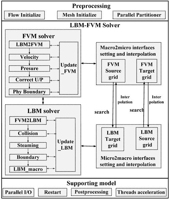
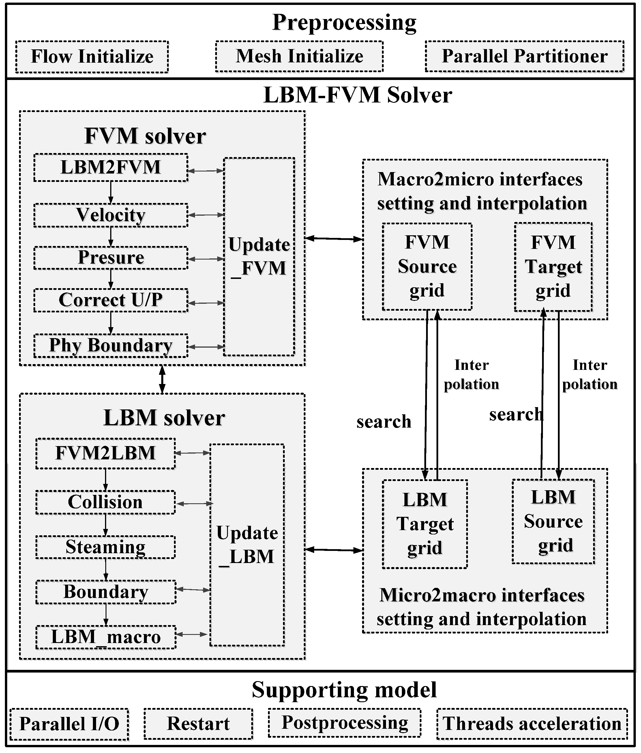
Our framework provides a flexible solution for CFD simulations through integrated architecture. The two numerical approaches may be adopted individually or coupled, as depicted in Figure 1. Designed as a comprehensive end-to-end simulation platform, it integrates three closely interlinked components: a preprocessing module, a supporting model, and a CFD solver. In the preprocessing module, the parallel partitioner includes PE layout between regions and domain decomposition in subregions. Flow and mesh initialization includes FVM and LBM data structures and field input and preprocessing. The coupled solver incorporates an FVM solver (MarineFlow v2.6; China Ship Scientific Research Center, Wuxi, China), an LBM solver (SWLBM v1.0; National Supercomputing Center in Wuxi, Wuxi, China), and an interface setting and interpolation model.
Figure 1.
Framework of LBM-FVM.
In the preprocessing module, we initialize the physical characteristics of the macroscopic algorithm and the mesoscopic algorithm and handle geometry ingestion through multi-format support. Then flexible domain decomposition is automatically configured according to the computational load of each domain and the total number of parallel processes. The communication modules and initialization are also realized.
In the LBM-FVM solver, the collocated grid is adopted. In FVM, the SIMPLE algorithm is used to break down the strong coupling between pressure and velocity. While in LBM, the solver adopts the D3Q19 discretization scheme and performs collision-propagation operations over the simulation time. In the interface setting and interpolation module, data conversion and transmission are performed. When coupling the FVM to LBM, information along the interface boundary is converted and transformed using the proposed reconstruction operator, and then LBM simulation is carried out in the LBM subregion. Once a temporary solution is obtained in LBM, macro variables are converted from LBM to the FVM solver in the LBM2FVM boundary. Additionally, a hybrid parallelization strategy that maximizes hardware utilization is employed.
When a certain number of iterations are completed or the simulation time ends, we launch the parallel I/O for output or restart, facilitating subsequent data processing, visualization, and analysis.
3.2. Processor Layout Strategies
Our LBM-FVM solver is a single executable program. Each model component undergoes autonomous evolution and modification, as well as seamless data interchange. Thus, the alterations in the entire system are reliant not just on the relatively autonomous evolution and modification of each model component but also on their interrelationships and the collective behavior they create. To optimize the global performance of the solver, we first design a multi-group partition strategy and then implement a multilevel parallelization and optimization strategy for the subdomains based on the New Sunway system.
3.2.1. Processor Layout Between Subdomains
During the execution of the coupled LBM-FVM solver, the constituent components advance in time through integration, with periodic interruptions for interface data exchange. Meanwhile, each solver receives the field data from the other solver, performs computations, and subsequently transmits the processed fields back to the respective solver. The coupling simulation has significant flexibility with respect to the layout of solvers across different hardware processors, as Equation (2) shows. denotes the computational cost within a subdomain, denotes the intra-subdomain communication cost, denotes the inter-subdomain coupling communication cost. The computational and communication times within a subdomain depend on the total number of processes allocated to that subdomain and the manner of domain decomposition, while the inter-subdomain communication and computational performance are determined by the number of coupling boundary cells and the process configuration across subdomains. For intra-process computations, we adopt the typical two-dimensional domain decomposition scheme [34]. The total simulation time is determined by the individual performance of each subregion and processor (PE) layout configuration between regions.
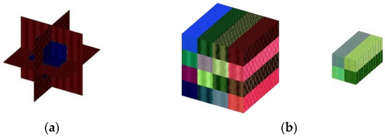
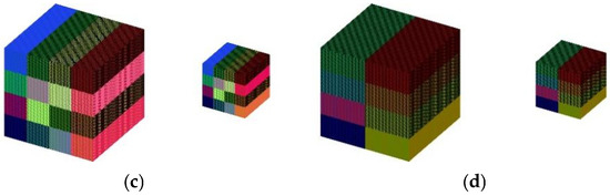
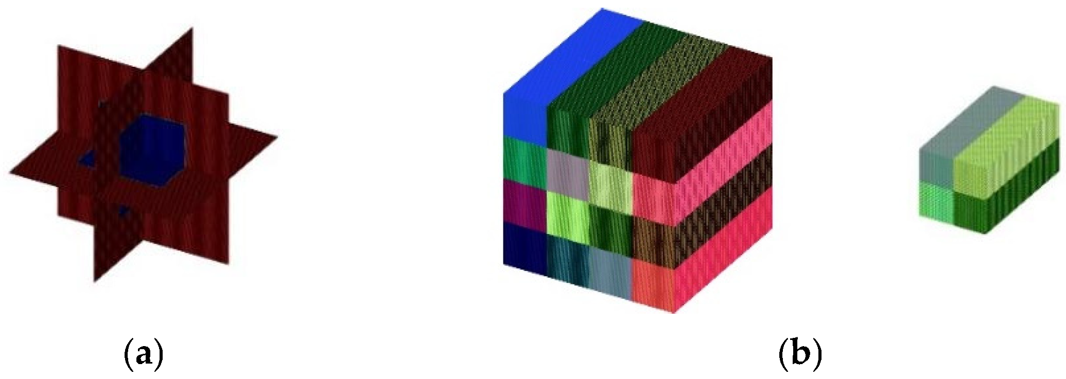
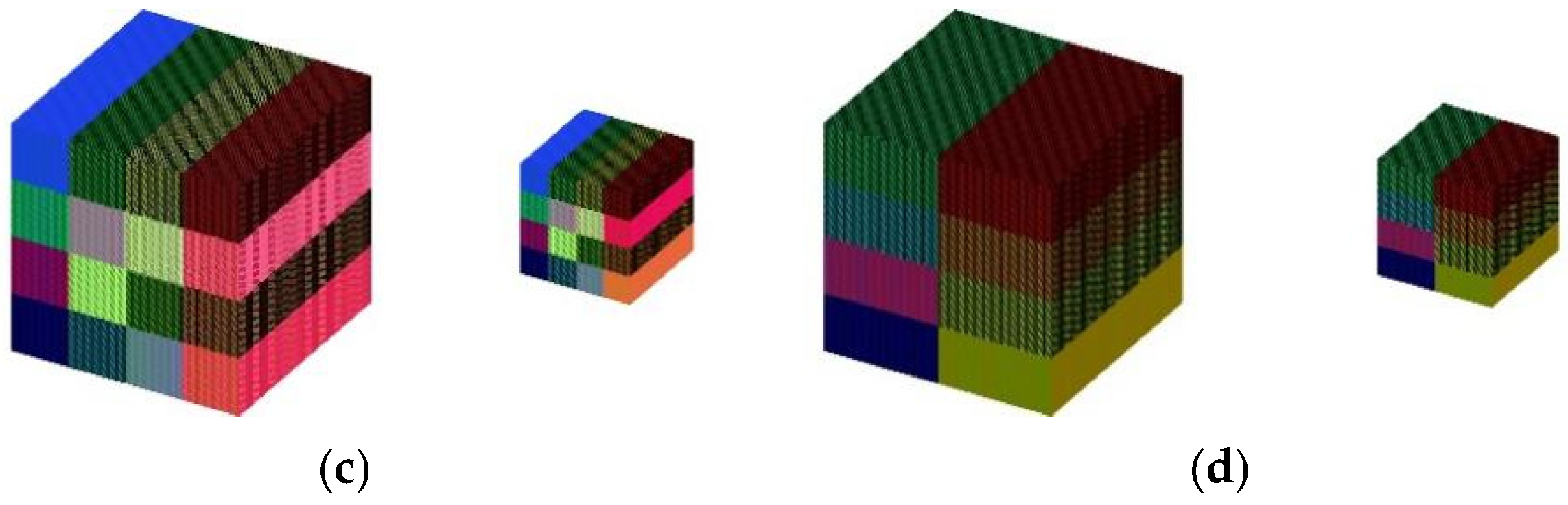
In this paper, we developed a significant flexibility PE layout. First, we adopt PE splitting to match the predicted timing information of each solver, and then we assign a unique MPI communicator for each solver. In addition, the interface boundary exchange is performed only on the union of responsible processors. By controlling these communicators, the two solvers can be executed sequentially, concurrently, or in a hybrid manner. Figure 2 shows three PE distributions for a 3D block.
Figure 2.
Optional PE distributions in LBM-FVM: (a) Computational domain; (b) PE layout 1; (c) PE layout 2; (d) PE layout 3.
For a given configuration across varied processor counts, the PE layout strategy can effectively improve load balancing for subregions and enable our program to take full advantage of the hardware resources. We have tested two multi-domain partitioning strategies for the coupled domains. Strategy 1, the cooperative partitioning approach, embeds the FVM grid within the overall LBM grid partition, resulting in an uneven distribution of LBM and FVM grids across processes, as illustrated in Figure 2b. Strategy 2, the grouped partitioning approach, partitions the LBM and FVM grids separately and distributes them evenly within process groups, achieving better load balance, as shown in Figure 2c. Test results indicate that a full-domain FVM simulation of 100 steps requires 2484.45 s on the New Sunway supercomputer. In the coupled mode using multi-domain partitioning Strategy 1, the runtime is reduced to 467.71s, and further decreases to 103.40 s using Strategy 2, demonstrating a significant improvement in simulation performance. It is worth mentioning that changing the processor layout of the solvers has no impact on the scientific results.
3.2.2. Domain Decomposition for Subregions
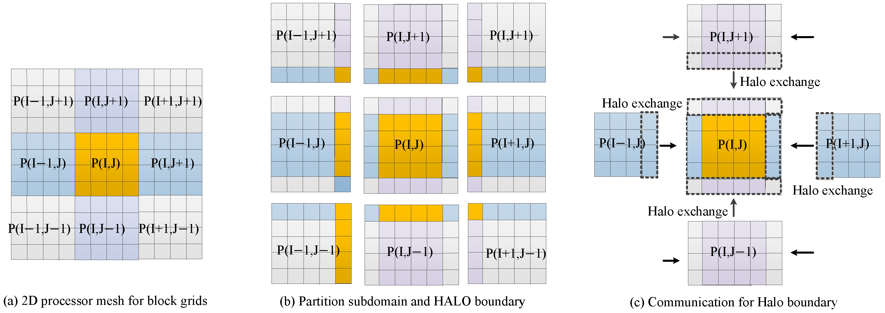
For the structured subregion of a single solver, we decompose the grid into multiple subgrids along two high-dimensional directions, with one subgrid assigned to each processor. Both LBM and FVM simulations fall into the stencil-like category, and each subgrid includes a partition boundary to meet the data requirements of the stencil, as illustrated in Figure 3.
Figure 3.
A 2D domain decomposition for subregion.
In structured grids, the boundary data lies among adjacent processors in the same row or column, that is, each processor needs to communicate with up to 8 adjacent processors to update boundary data. To reduce communication latency, we reorder the data communication mode:
First, we package the communication data for the X-dimension and complete inter-processor communication along the X-direction. At this point, the data from the corner processors are ready and are contiguous in the top and bottom neighbor processors. Therefore, we transmit additional corner data when performing boundary communication along the Y-direction. Additionally, we further employ an MPI non-blocking communication mode to improve performance.
3.3. Parallelization Design for CPEs on the New Sunway System
3.3.1. Redesigning of LBM
The collision and propagation operators represent the most critical computational hotspots in LBM. The collision operation is local and neither depends on nor requires information from other grid points. The streaming process is stencil-like and needs the distribution functions from the neighboring cells. To ensure data consistency between processes, a boundary region is introduced to store the distribution functions of the existing subdomains, which is referred to as HALO cells. In one iteration step, the LBM program is implemented by alternately executing collision, propagation, communication, and so on. As described in [35], the CPEs of SW26010P only support part of the instruction sets and data transferred to the MPE. This process incurs two types of time overhead:
(1) MPI communication cost.
(2) Data transfer cost between main memory and device memory.
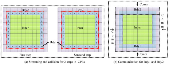
As we know, the limited memory bandwidth and communication are major factors affecting overall performance. To address these limitations, we restructure the computational workflow of LBM and implement an optimization strategy of “trading computing for communication”, as illustrated in Figure 4.
Figure 4.
Restructured the computational workflow of LBM.
In our implementation, two layers of HALO boundaries are set in LBM. This configuration is determined by a trade-off between the distribution function reconstruction algorithm and computational efficiency. The nonlinear velocity distribution function reconstruction method adopted in this work (see Equation (1)) explicitly incorporates flow field gradient terms during the reconstruction process. To ensure reconstruction accuracy at the interface, the gradient terms are discretized using a second-order central difference scheme. Under this discretization, the stencil required for the central difference computation demands at least two layers of grid points near the interface; therefore, two HALO layers are set in the LBM subdomain accordingly. Further increasing the number of HALO layers does not provide essential improvements in numerical stability or consistency but increases the number of grid points involved in each timestep, thereby introducing additional computational and communication overhead. A similar three-layer overlapping setup is employed in the design of the FVM2LBM subdomain, where the choice is likewise based on the stencil requirements of the employed algorithm and the accuracy requirements at the interface.
At an even time step, naive communication and HALO cell updating are performed with data from neighboring subdomains. Then the collision and streaming functions of two iteration steps are merged and transformed to the CPEs. By virtue of the locality of LBM, we obtain fully correct distribution functions in the first inner loop for the blue HALO boundary layer and inner domain, while in the second inner loop, the distribution functions in the inner domain are also consistent. As subsequent data communication is performed, it does not matter whether the data for the blue HALO boundary in the second loop step is correct or not. The original communication and computation workflow are also retained for handling scenarios where Nstep is not divisible by 2. After restructuring, the communication and one data transfer process are reduced by half.
3.3.2. Memory Access Optimization Strategies
On the SW26010P processor, the high-efficiency Local Data Memory (LDM) on the Computing Processing Elements (CPEs) has a limited capacity of 256 KB. The LDM is precious and cannot hold all required data. Therefore, a finer blocking scheme and data reuse are crucial for the CPEs to achieve better performance for various applications.
Assuming NCELL stands for the grid cell numbers, NL denotes the dimension of the low-dimensional space, PBit represents the number of bytes occupied by the type, and N refers to the number of arrays allocated on CPES. The formula is ensured as follows:
Based on Equation (3), we can get the maximum cell blocks copied to the LDM using one DMA operation. Since data are stored contiguously along the z-axis, the cells are divided into multiple cuboidal blocks in the z direction. Subsequently, the partitioning of CPE tasks is carried out along the X-dimension. The refined blocking strategy at the CPE level guarantees improved DMA bandwidth utilization and balanced load distribution across CPEs.
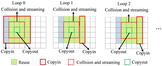
Furthermore, the stencil-like data computing is processed sequentially, and most of the read-only data are repeated between steps. This creates the opportunity for data reuse and data sharing among CPEs. As shown in Figure 5, data reuse is performed cyclically along the Y-dimension.
Figure 5.
Data reuse strategy of LBM.
In the merged collision and streaming implementation, 4/5 of the data can be reused for the first collision-propagation step, while 2/3 of the data can be reused for the second collision-propagation step. Additionally, a grid network and a low-latency communication mechanism called Remote Memory Access (RMA) are also employed in the X direction, which enables fast data sharing among CPEs.
3.3.3. Vectorization
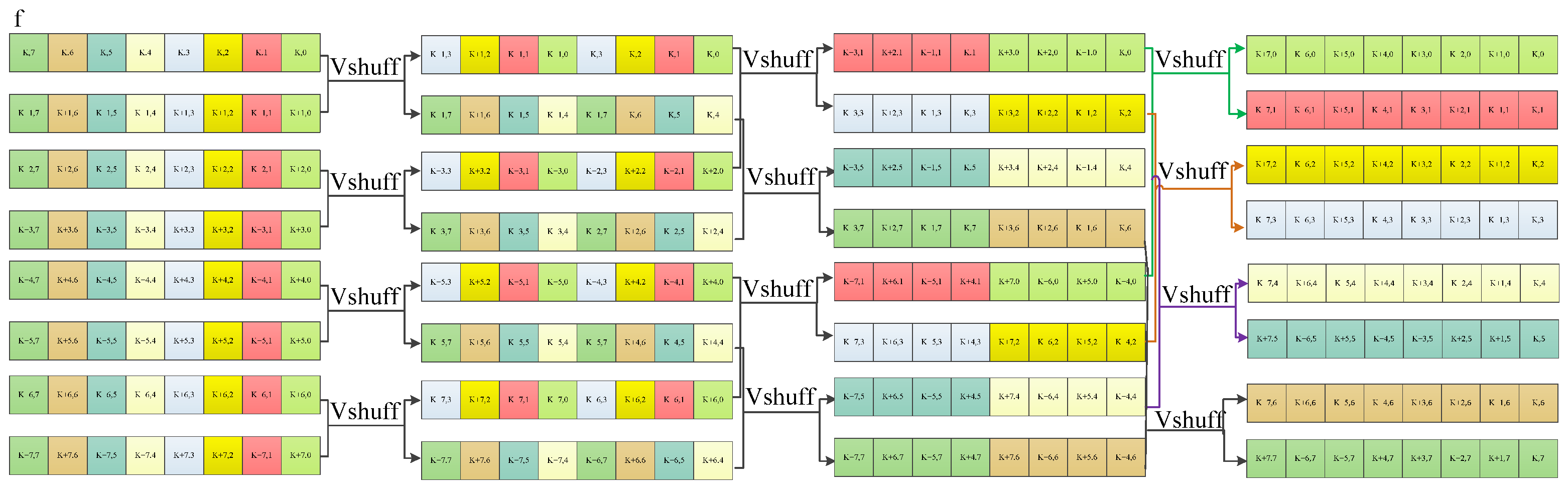
Vectorization is a key optimization technique in high-performance computing. It enables parallel processing of data arrays by converting multiple scalar instructions into a single vector instruction. On the SW26010P processor, 512-bit vector registers are supported to hold 8 double-precision data at once, and operations can perform the same computation on these elements simultaneously. The vector registers can significantly improve computational efficiency and reduce the number of instructions executed, but they face challenges with data alignment and dependencies.
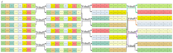
To navigate through the thorns of hardware constraints and software compatibility, we expand the directions of a cell to ensure that data are naturally 512-bit aligned and then employ it for shuffling instructions. As shown in Figure 6, we realize transposition and decouple the data dependencies and fully unleash the hardware’s computational potential.
Figure 6.
Data shuffling on SW26010P.
4. Experimental and Performance Results
4.1. Correctness Test for LBM-FVM Solver
Lid-driven cavity flows are not only technologically important but also of great scientific interest, exhibiting many kinds of fluid mechanical phenomena. In this paper, we applied our parallel coupling to simulate most classic benchmarks of 2D and 3D lid-driven cubic cavity flows.
4.1.1. 2D Lid-Driven Flow
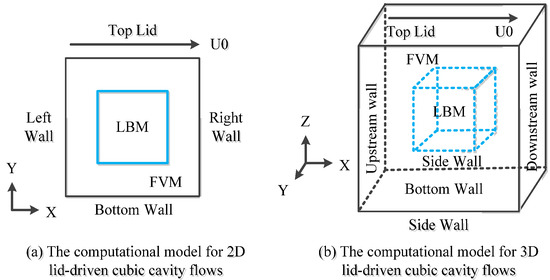
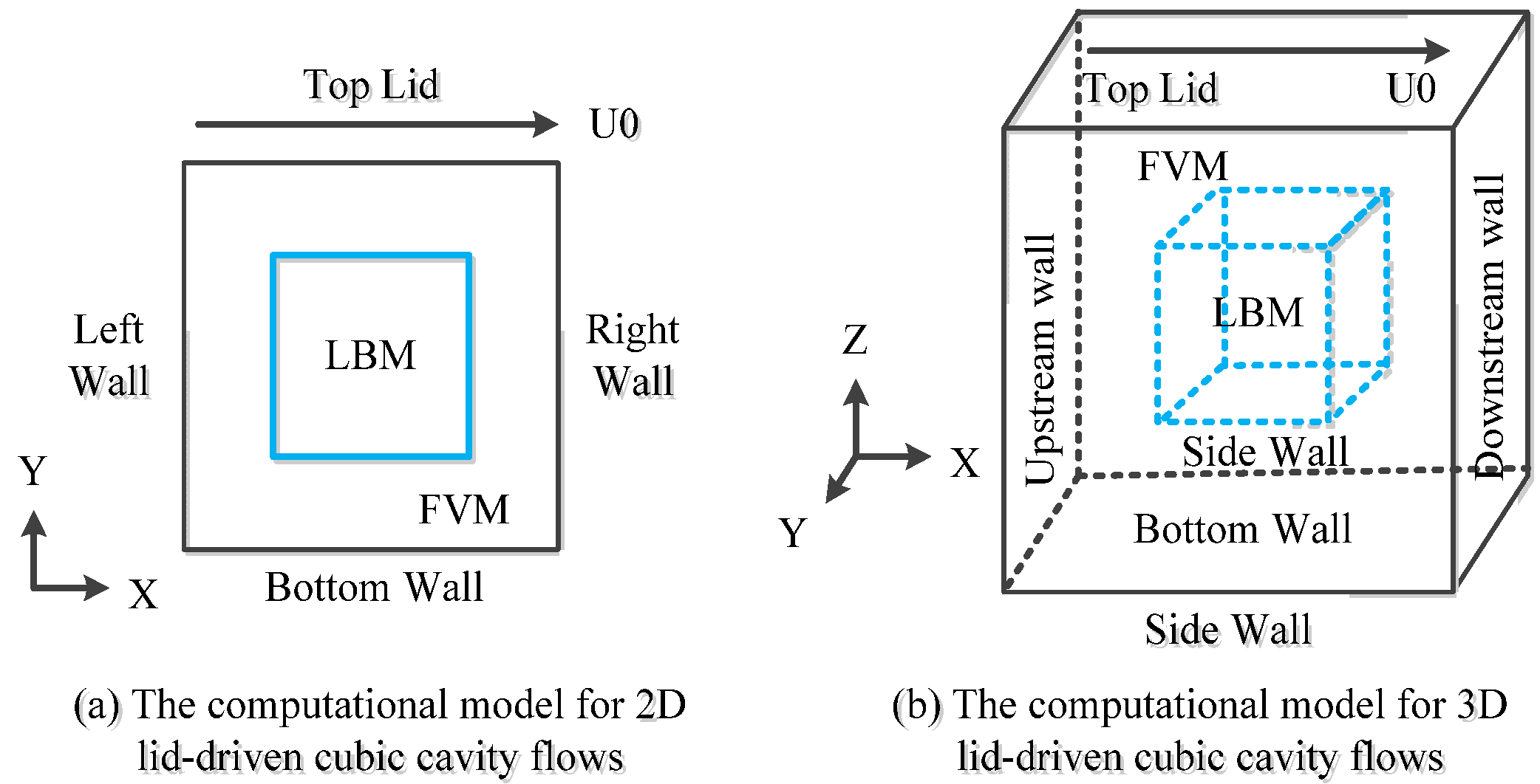
The schematic diagram of our experiments is shown in Figure 7a. All the walls of the cavity are stationary except the top wall, which moves with a velocity U0. The computational domain is decomposed into two regions, where different methods are used, respectively. The LBM2FVM subdomains overlap by two layers, while the FVM2LBM subdomains overlap by three layers. The total grid is 200 × 200, while the domain solved by LBM is [70,129] × [70,129]. In these tests, identical grid resolution is used. Table 1 summarizes the locations of vortices for our cases of Re = 100, 400, 1000, and 100,000 and compares them with literature results.
Figure 7.
Definitions for lid-driven cavity flow.
Table 1.
The central locations of vortices for lid-driven cavity for Re = 100, 400, 1000, and 100,000 compared with Ghia’s work [36].
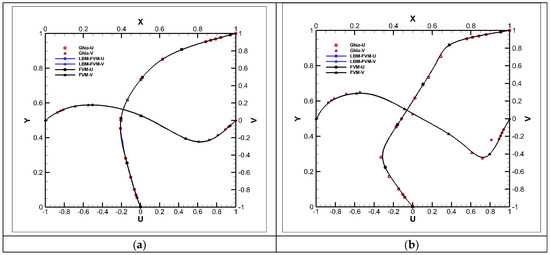
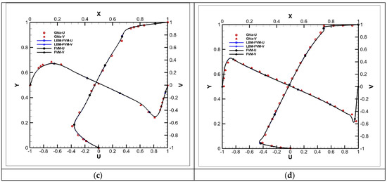
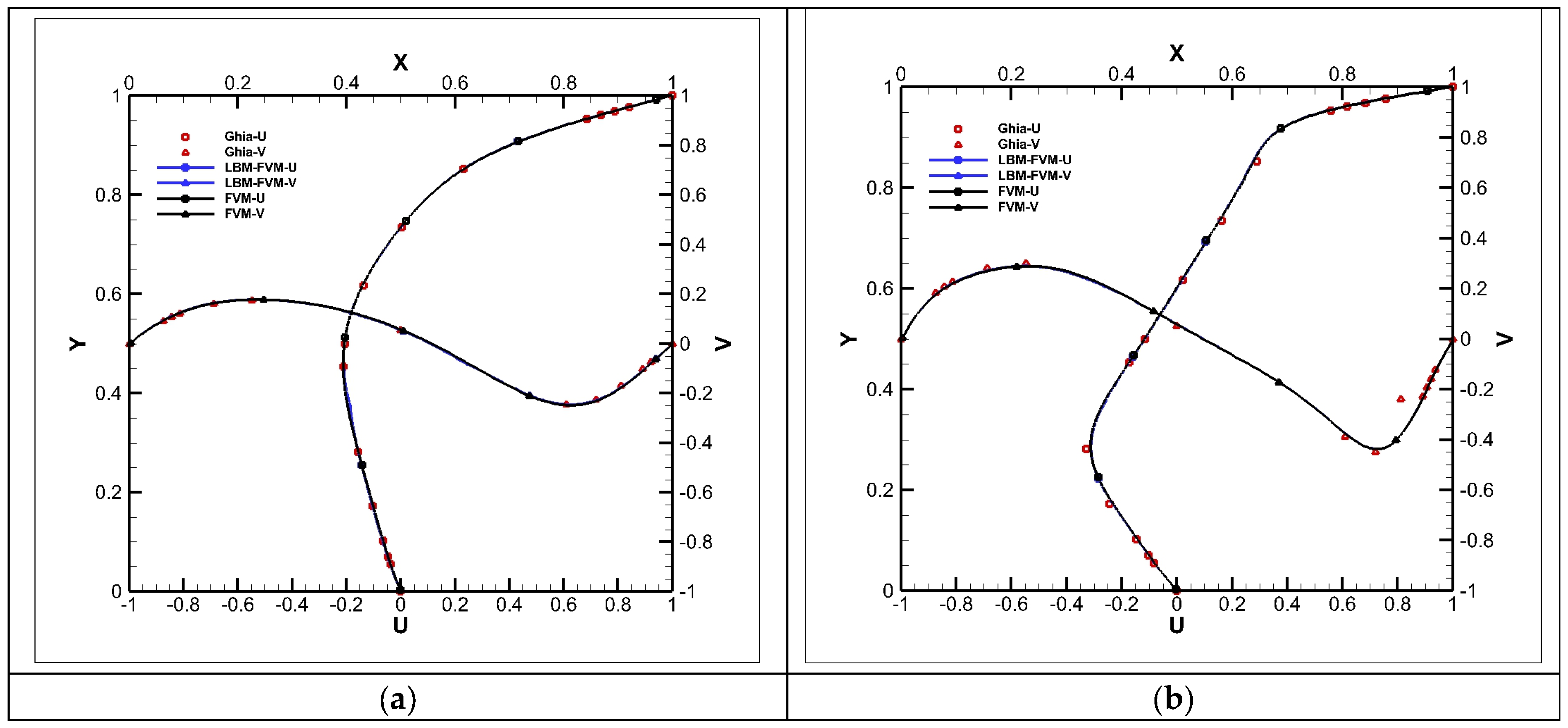
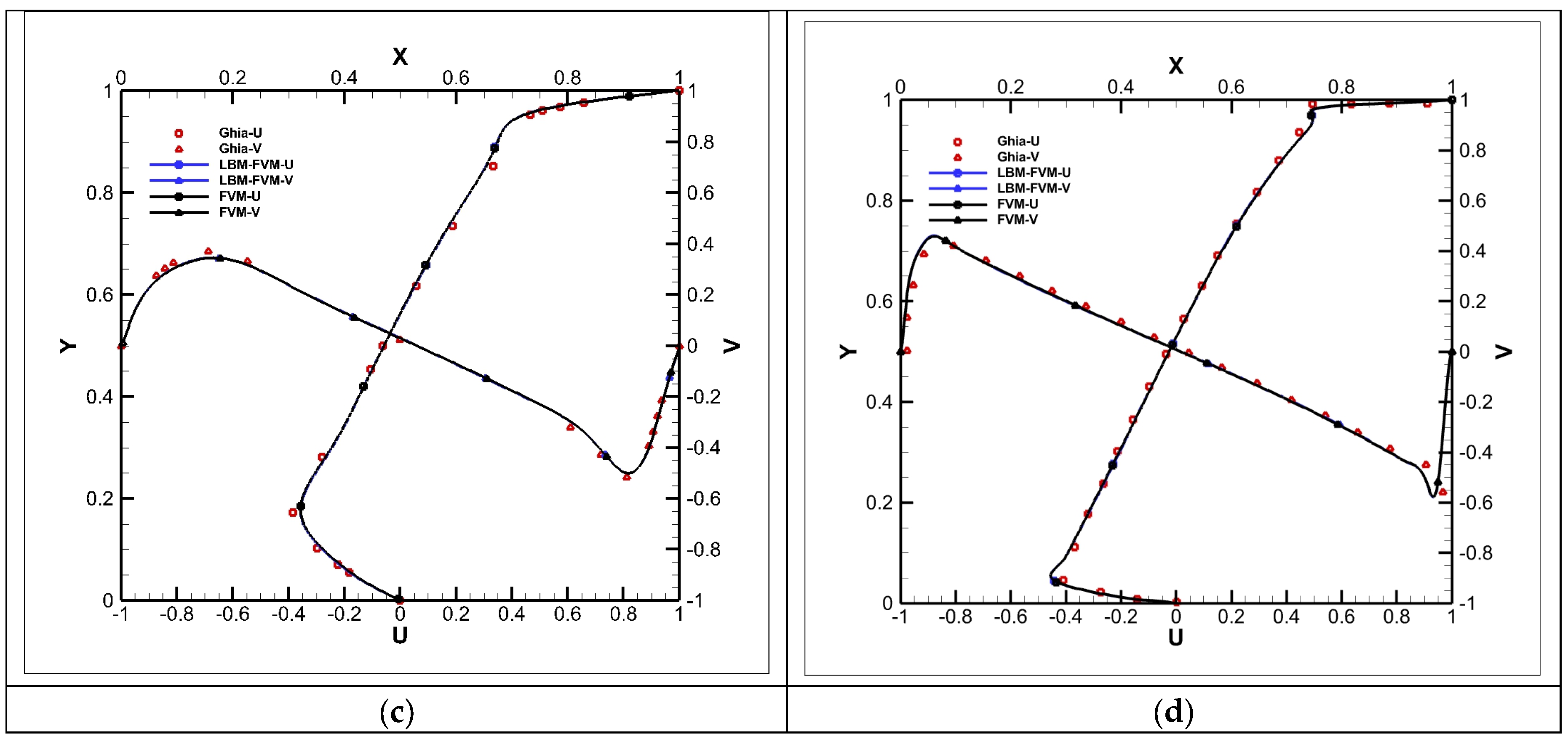
Figure 8 displays the mean velocity on the mid-plane of the cavity. For different Re, the results of velocity components are in overall agreement with existing experimental data.
Figure 8.
Velocity components along two centerlines: (a) Re = 100; (b) Re = 400; (c) Re = 1000; (d) Re = 10,000, compared with Ghia [36] results.
4.1.2. 3D Lid-Driven Flow
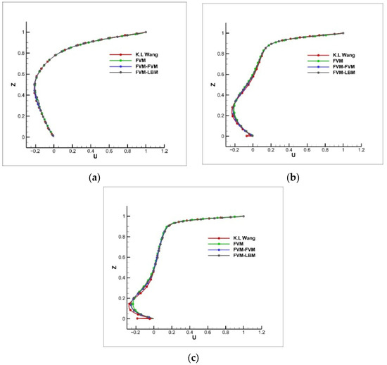
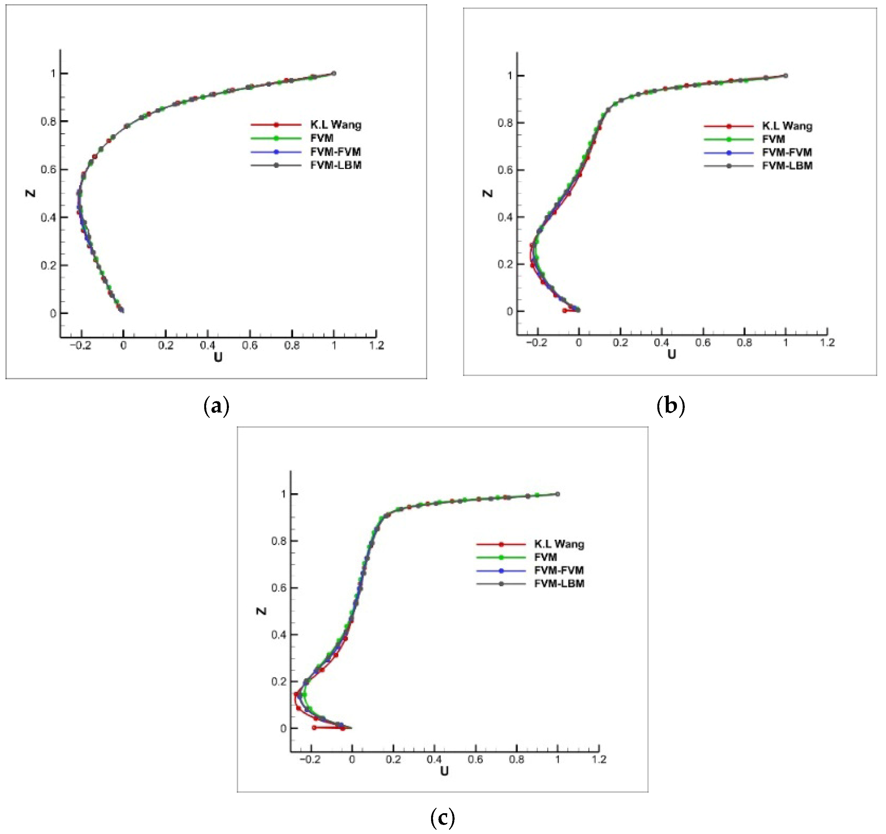
A schematic diagram of our selected 3D lid-driven cavity is shown in Figure 7b. Numerical simulations were carried out for cavity flow of Re = 100, 400, 1000, and 10,000 on a 200 × 200 × 200 grid, and the domain solved by LBM is [70,129] × [70,129] × [70,129]. For simplicity, only the results for velocity U along the vertical and horizontal centerlines in the symmetry planes of the cavity are presented, as shown in Figure 9.
Figure 9.
Velocity components in the symmetry planes: (a) Re = 100; (b) Re = 400; (c) Re = 1000 compared with Wang’s work [37].
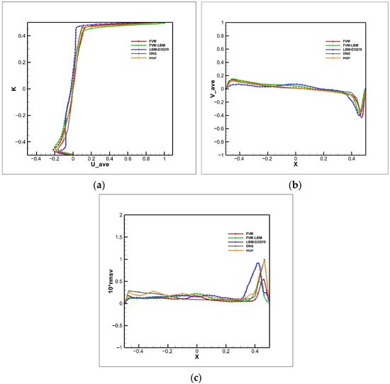
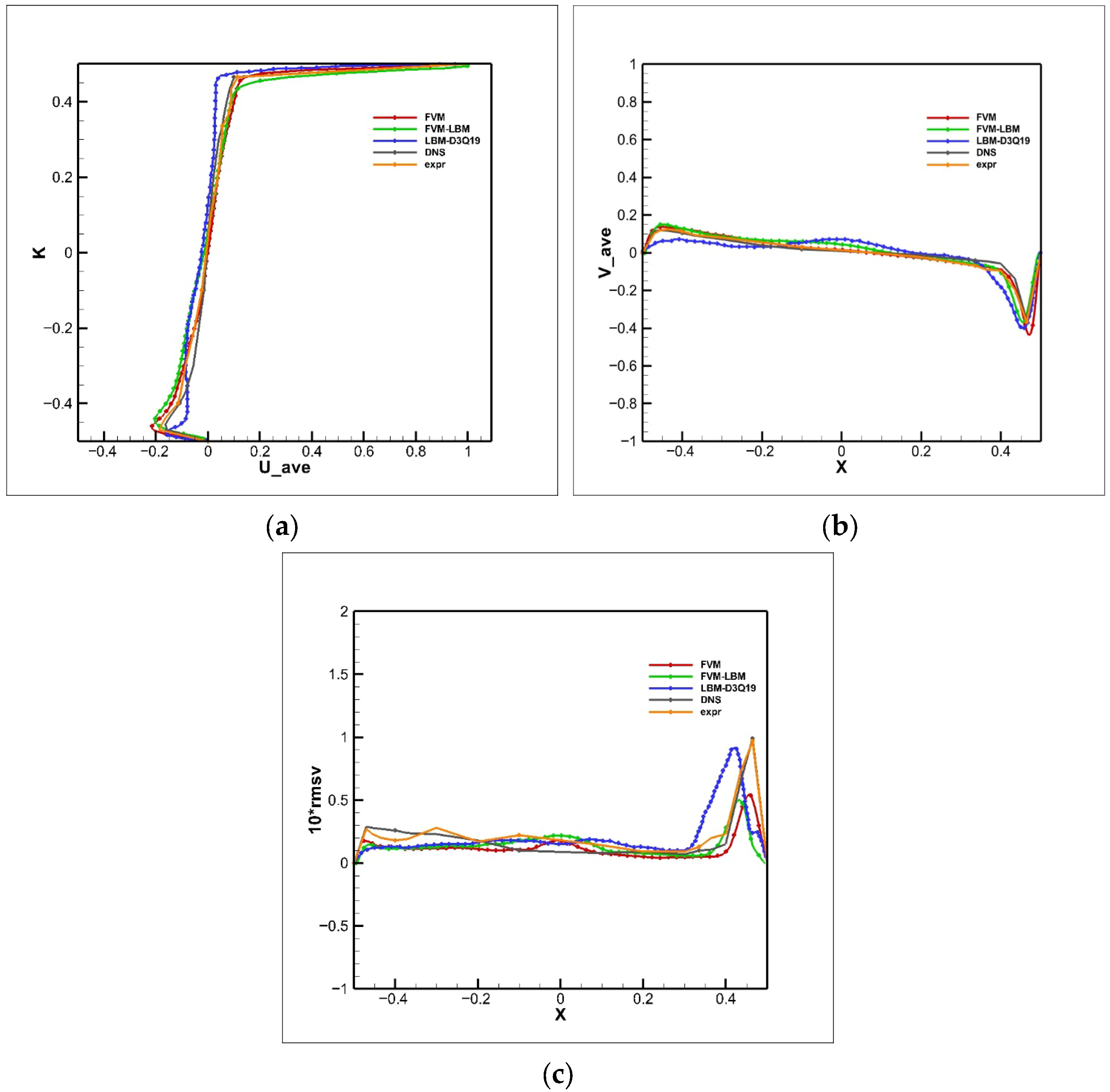
According to numerical experience, the rms velocity representing “turbulent” velocity fluctuations is the most difficult to obtain for such coupled computation. Figure 10 is a schematic representation of rms velocity at Re = 10,000. For simplicity, only the result for the rms velocity of LES is presented. It is seen that the good agreement between our LBM-FVM with single FVM and experiments is again obtained.
Figure 10.
Mean and rms V profiles in the symmetry planes for Re = 10,000: (a) U mean; (b) V mean; (c) V rms, compared with Liou et al. LBM-D3Q19 results [38], Park DNS results [39], and the experimental data of Prasad and Koseff [40].
4.2. Performance Results
4.2.1. Optimization Results of LBM
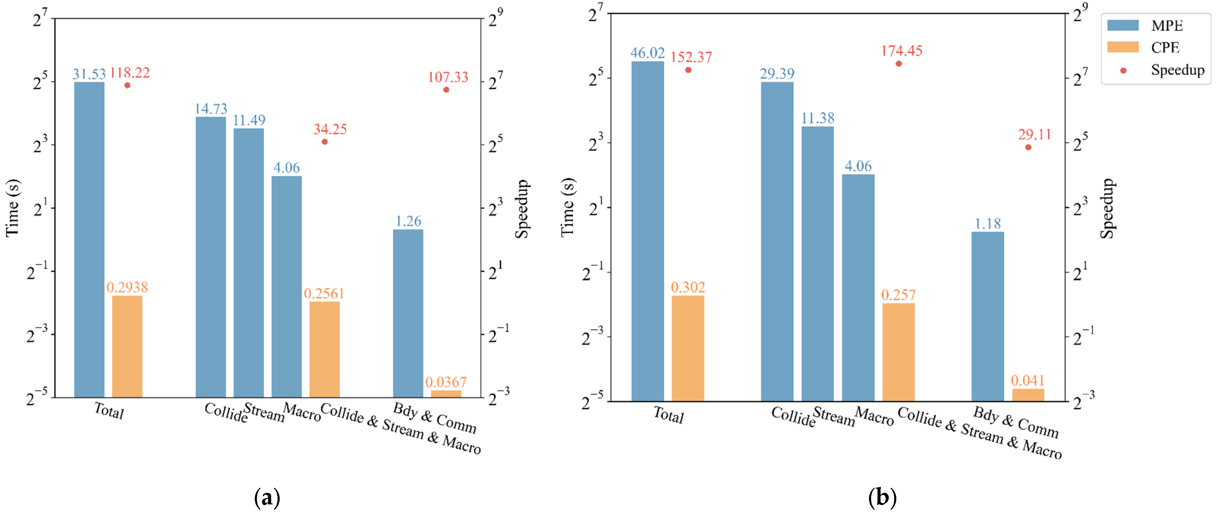
In this section, we evaluate our optimization results of LBM realized on the new Sunway supercomputer. In these cases, simulations are performed on a 460 × 220 × 240 grid using 64 MPEs. We measure the performance using the average time recorded for running the same case for 20 steps and adopt the performance of the original version that uses MPEs as the benchmarking baseline.
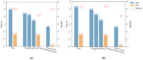
Figure 11 shows the performance improvement and speedup with and without LES-SGS turbulence modelling. The majority of kernels within the LBM involve boundary exchange, collision, streaming, and macros. Notably, the case with the LES-SGS model shows a higher speedup of 152×, as more computation is involved.
Figure 11.
The running time and optimization results of LBM on SW26010P processor: (a) no LES; (b) LBM-LES.
4.2.2. Optimization Results of LBM-FVM
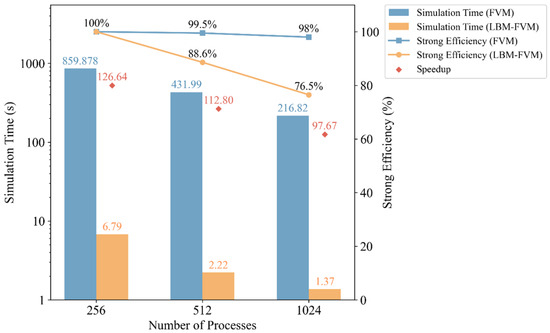
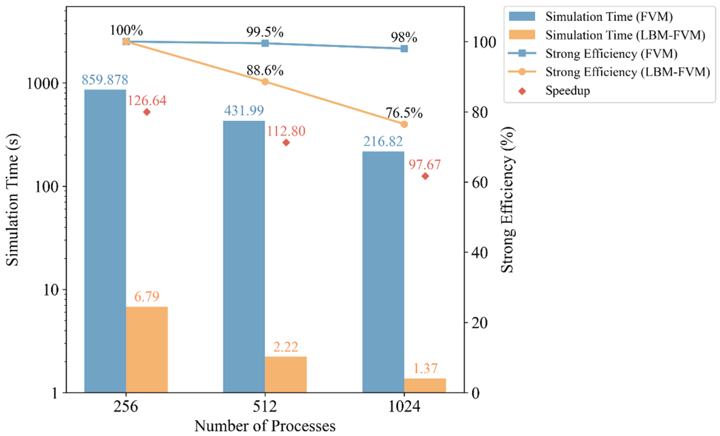
For scaling tests, we conduct simulations of 3D lid-driven cavities to evaluate the scalability and performance. For the single FVM simulation, the total number of grid cells is 1024 × 1024 × 1024. For the LBM-FVM coupled simulation, the grid cells for LBM are the same as the single FVM simulation, and the grid size of FVM is 128 × 28 × 128. The domain of FVM simulation is located in the center of the domain for LBM. All benchmark codes in this work have been optimized and compiled with the O2 optimization option. Running the FVM in MPE-only mode with 256 processes required 859.878 s. The total runtime and the runtime of each component for the coupled mode using MPE and CPE are presented in Table 2, achieving a maximum speedup of 126.6× for the LBM-FVM coupled simulation compared with the single FVM simulation.
Table 2.
Total and per-component runtimes on MPE and CPE.
Figure 12 demonstrates the strong scaling outcomes of the single FVM simulation and the LBM-FVM coupled simulation. Scaling from a baseline configuration of 256 CG to 1024 CG, the strong scaling efficiency of LBM-FVM reached 76.5%. The parallel efficiency of LBM-FVM exhibits a comparable decrease compared to the single FVM simulation, due to the reduced utilization in interface boundary exchanges.
Figure 12.
The strong scaling outcomes of single FVM simulation and LBM-FVM coupled simulation.
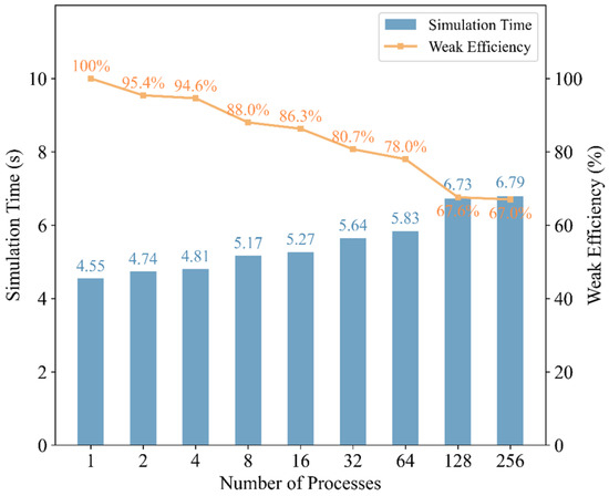
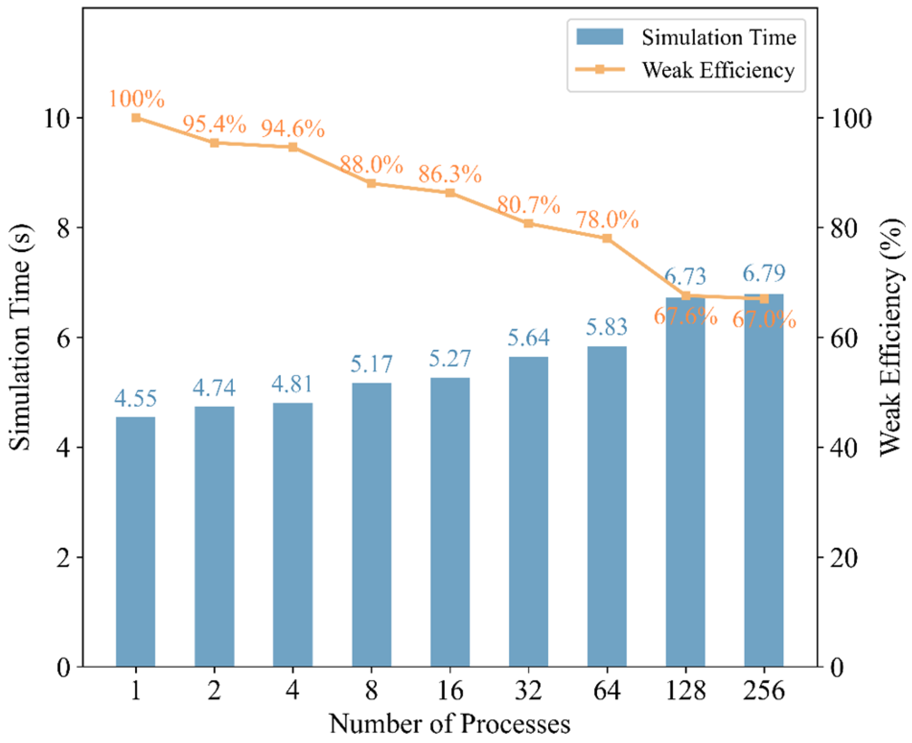
Figure 13 demonstrates the weak scaling outcomes. For weak scaling tests, each CG contains 4,194,304 LBM grid cells and 8192 FVM grid cells. In 2023, we extended LBM to 39 million cores on the New Sunway supercomputer [41], achieving 82.9% memory bandwidth utilization. This work focuses only on the performance of the LBM-FVM coupling.
Figure 13.
The weak scaling outcomes of LBM-FVM.
We scale from 1 CG to 256 CG with about 1 billion cells for the largest run and achieve 67.0% parallel efficiency. The parallel efficiency decreases due to the imbalance of the interface boundary exchanging and the communication within subregions and between regions.
5. Conclusions
In this paper, we present a flexible framework and an optimization scheme for our LBM-FVM coupled solver. We design processor layout strategies to break down bottlenecks between load imbalance and communication redundancy in the coupled solver and then construct a multi-level parallel optimization scheme for the LBM solver based on the new Sunway supercomputer. We redesign the computational workflow of LBM and implement an optimization strategy of “trading computing for communication”. Furthermore, we implement several techniques, including kernel fusion, a data sharing scheme, and SIMD strategies for targeted kernels. Our optimization results of LBM show a speedup ratio of 152× for the LBM-SGS model.
We have also conducted a series of benchmark tests to verify the correctness and efficiency of the LBM-FVM coupled solver, including 2D lid-driven cavity flow and 3D lid-driven cavity flow tests. The results show that the coupled solver can correctly capture flow characteristics and achieve consistent vortex with experimental data. Meanwhile, compared with the standalone FVM solver, the coupled solver can achieve a maximum speedup of 126×. Additionally, the parallelized LBM-FVM solver achieves a strong scaling efficiency of 76.5% and a weak scaling efficiency of 67.0%.
The coupled solver framework and optimization methods proposed in this study deeply integrate the inherent characteristics of LBM and FVM, achieving superior computational performance by leveraging the high multilevel parallelizability of LBM. The method proposed in this work offers a feasible approach for solving industrially relevant multiphysics flow problems. Applications include direct simulation of flow-induced noise for underwater vehicles, large-scale far-field wake capture, transport phenomena and pore-scale processes, and heat transfer in porous heat sinks, among other multiscale phenomena. Future work will further extend the method’s applicability under complex operating conditions.
Author Contributions
Conceptualization, Z.L. and C.W.; Methodology, Z.L. and C.W.; Software, X.C. (LBM algorithm), J.W. and Y.Z. (FVM algorithm); Validation, Y.J.; Formal Analysis, X.L.; Investigation, X.L.; Data Curation, X.L.; Writing—Original Draft Preparation, X.L. and Y.F.; Writing—Review and Editing, X.L., Y.F., C.W. and Z.L.; Visualization, X.L. and Y.F.; Supervision, C.W. and Z.L.; Project Administration, C.W.; Funding Acquisition, C.W. and Z.L. All authors have read and agreed to the published version of the manuscript.
Funding
The research is supported by the development and application project of ship CAE software, National Key Research and Development Program of China, grant number 2025YFB3003202 and 2023YFB3002404, Pilot Research Program of WIIRI, Science and Technology Project of Jiangsu Province, grant number BM2022028, Science and Technology Innovation Project of Laoshan Laboratory, grant number LSKJ202202204.
Institutional Review Board Statement
Not applicable.
Informed Consent Statement
Not applicable.
Data Availability Statement
The raw data supporting the conclusions of this article will be made available by the authors on request.
Acknowledgments
All authors gratefully acknowledge the fund support of the development and application project of ship CAE software.
Conflicts of Interest
Authors Chengsheng Wu, Yaying Zhang and Yixing Jin were employed by the company CSSC Orient Wuxi Software Technology Co., Ltd. The remaining authors declare that the research was conducted in the absence of any commercial or financial relationships that could be construed as a potential conflict of interest.
References
- Liu, Y.; Liu, L.; Zhou, W.; Wei, J. A study of convective heat transfer by using the hybrid MD-FVM method. J. Mol. Liq. 2021, 340, 117178. [Google Scholar] [CrossRef] [Scilit]
- Wang, Y.; Zhou, W. A dynamic coupling scheme for fluid system by combining lattice Boltzmann method and molecular dynamics. Int. J. Mod. Phys. C 2025, 36, 2450178. [Google Scholar] [CrossRef] [Scilit]
- Garg, G.; Bhandarkar, U.; Puranik, B. A hybrid finite volume—Direct simulation Monte Carlo solution methodology for multi-species axisymmetric rotating flows. SSRN 2025. preprint. [Google Scholar] [CrossRef] [Scilit]
- Miao, H.; Mu, L.; Yin, H.; Wang, S.; Dong, M.; Shang, Y.; Pu, H. Hybrid lattice Boltzmann-finite volume method for solving coupled radiation-convection heat transfer in complex geometries. Int. Commun. Heat Mass Transf. 2025, 164, 108963. [Google Scholar] [CrossRef] [Scilit]
- Ma, Y.; Xiao, X.; Li, W.; Desbrun, M.; Liu, X. Hybrid LBM–FVM solver for two-phase flow simulation. J. Comput. Phys. 2024, 506, 112920. [Google Scholar] [CrossRef] [Scilit]
- Xu, H. (Xi’an Jiaotong University, Xi’an, China); Luan, H.B. (Xi’an Jiaotong University, Xi’an, China); Tao, W.Q. (Xi’an Jiaotong University, Xi’an, China). A Correction Lifting Relation of Macroscopic Variables and Microscopic Variables in Lattice Boltzmann Method. Unpublished Work. 2011. [Google Scholar]
- Xu, H. Lattice Boltzmann Model for Turbulent Fluid Flow Simulations and Its Application in Multiscale Analysis. Ph.D. Thesis, Xi’an Jiaotong University, Xi’an, China, 2009. [Google Scholar]
- Xu, H.; Luan, H.; He, Y.; Tao, W.Q. A lifting relation from macroscopic variables to mesoscopic variables in lattice Boltzmann method: Derivation, numerical assessments and coupling computations validation. Comput. Fluids 2012, 54, 92–104. [Google Scholar] [CrossRef] [Scilit]
- He, Y.L.; Tao, W.Q. Multiscale simulations of heat transfer and fluid flow problems. J. Heat Transf. 2012, 134, 031001. [Google Scholar] [CrossRef] [Scilit]
- Luan, H.; Xu, H.; Chen, L.; Tao, W.Q. Coupling Between FVM and LBM for Heat Transfer and Fluid Flow. Chin. Sci. Bull. 2010, 55, 3128–3140. [Google Scholar] [CrossRef] [Scilit]
- Chen, L.; Luan, H.; Feng, Y.; Song, C.; He, Y.L.; Tao, W.Q. Coupling between finite volume method and lattice Boltzmann method and its application to fluid flow and mass transport in proton exchange membrane fuel cell. Int. J. Heat Mass Transf. 2012, 55, 3834–3848. [Google Scholar] [CrossRef] [Scilit]
- Chen, L.; He, Y.L.; Kang, Q.; Tao, W.Q. Coupled numerical approach combining finite volume and lattice Boltzmann methods for multi-scale multi-physicochemical processes. J. Comput. Phys. 2013, 255, 83–105. [Google Scholar] [CrossRef] [Scilit]
- Tong, Z.X.; He, Y.L.; Tao, W.Q. A review of current progress in multiscale simulations for fluid flow and heat transfer problems: The frameworks, coupling techniques and future perspectives. Int. J. Heat Mass Transf. 2019, 137, 1263–1289. [Google Scholar] [CrossRef] [Scilit]
- Luan, H.B.; Xu, H.; Chen, L.; Sun, D.L.; He, Y.L.; Tao, W.Q. Evaluation of the coupling scheme of FVM and LBM for fluid flows around complex geometries. Int. J. Heat Mass Transf. 2011, 54, 1975–1985. [Google Scholar] [CrossRef] [Scilit]
- Li, Z.; Yang, M.; Zhang, Y. A coupled lattice Boltzmann and finite volume method for natural convection simulation. Int. J. Heat Mass Transf. 2014, 70, 864–874. [Google Scholar] [CrossRef] [Scilit]
- Zou, S.; Yuan, X.F.; Yang, X.; Yi, W.; Xu, X. An integrated lattice Boltzmann and finite volume method for the simulation of viscoelastic fluid flows. J. Non-Newton. Fluid Mech. 2014, 211, 99–113. [Google Scholar] [CrossRef] [Scilit]
- Zhou, Y.; Santasmasas, M.C.; De Rosis, A.; Hinder, I.; Moulinec, C.; Revell, A. A coupled finite volume-lattice Boltzmann method for incompressible internal flows. Comput. Phys. Commun. 2025, 314, 109686. [Google Scholar] [CrossRef] [Scilit]
- Latt, J.; Chopard, B.; Malaspinas, O.; Deville, M.; Michler, A. Straight velocity boundaries in the lattice Boltzmann method. Phys. Rev. E 2008, 77, 056703. [Google Scholar] [CrossRef] [Scilit]
- Gourdain, N.; Gicquel, L.; Montagnac, M.; Vermorel, O.; Gazaix, M.; Staffelbach, G.; Garcia, M.; Boussuge, J.F.; Poinsot, T. High performance parallel computing of flows in complex geometries: I. methods. Comput. Sci. Discov. 2009, 2, 015003. [Google Scholar] [CrossRef] [Scilit]
- Álvarez-Farré, X.; Gorobets, A.; Trias, F.X. A hierarchical parallel implementation for heterogeneous computing. Application to algebra-based CFD simulations on hybrid supercomputers. Comput. Fluids 2021, 214, 104768. [Google Scholar] [CrossRef] [Scilit]
- Queutey, P.; Guilmineau, E.; Visonneau, M.; Wackers, J.; Deng, G. RANS and Hybrid RANS-LES simulations around the Japan Bulk Carrier of the Tokyo 2015 CFD Workshop. In Proceedings of the 19th Numerical Towing Tank Symposium, St. Pierre d’Oleron, France, 3–4 October 2016. [Google Scholar]
- Jasak, H.; Vukčević, V.; Gatin, I.; Lalović, I. CFD validation and grid sensitivity studies of full scale ship self propulsion. Int. J. Nav. Archit. Ocean. Eng. 2019, 11, 33–43. [Google Scholar] [CrossRef] [Scilit]
- Pena, B.; Huang, L. A review on the turbulence modelling strategy for ship hydrodynamic simulations. Ocean Eng. 2021, 241, 110082. [Google Scholar] [CrossRef] [Scilit]
- Asada, H.; Kawai, S. Fully-automated high-fidelity LES around high-lift aircraft configuration near stall. In Proceedings of the Eleventh International Conference on Computational Fluid Dynamics, Maui, HI, USA, 11–15 July 2022. [Google Scholar]
- Tamaki, Y.; Asada, H.; Takaki, R.; Kawai, S. Wall-modeled LES around the CRM-HL using fully-automated Carte-sian-grid-based flow solver FFVHC-ACE. In Proceedings of the AIAA AVIATION 2022 Forum, Chicago, IL, USA, 27 June–1 July 2022. Paper No. AIAA 2022-3435. [Google Scholar]
- Afzal, A.; Saleel, C.A.; Prashantha, K.; Bhattacharyya, S.; Sadhikh, M. Parallel finite volume method-based fluid flow computations using OpenMP and CUDA applying different schemes. J. Therm. Anal. Calorim. 2021, 145, 1891–1909. [Google Scholar] [CrossRef] [Scilit]
- Wang, C.; Xia, J.; Chen, L. A heterogeneous hybrid-precision finite volume method for compressible flow on unstructured grids. Comput. Fluids 2025, 288, 106505. [Google Scholar] [CrossRef] [Scilit]
- Xue, W.; Wang, H.; Roy, C.J. CPU–GPU heterogeneous code acceleration of a finite volume computational fluid dynamics solver. Future Gener. Comput. Syst. 2024, 158, 367–377. [Google Scholar] [CrossRef] [Scilit]
- Körner, C.; Pohl, T.; Rüde, U.; Thürey, N.; Zeiser, T. Parallel lattice Boltzmann methods for CFD applications. In Numerical Solution of Partial Differential Equations on Parallel Computers; Springer: Berlin/Heidelberg, Germany, 2006; pp. 439–466. [Google Scholar]
- Schornbaum, F.; Rüde, U. Massively parallel algorithms for the lattice Boltzmann method on nonuniform grids. SIAM J. Sci. Comput. 2016, 38, C96–C126. [Google Scholar] [CrossRef] [Scilit]
- Meng, W.; Yang, S.; Lu, X.; Peng, Y.; Diao, W.; Zhang, C. Lattice Boltzmann model and its GPU acceleration for transient flow in channel and pressurized pipe combined water delivery system. Appl. Water Sci. 2025, 15, 60. [Google Scholar] [CrossRef] [Scilit]
- Tao, S.; Li, Q.; Zhou, Q.; Han, Z.; Lu, L. Optimization Research of Heterogeneous 2D-Parallel Lattice Boltzmann Method Based on Deep Computing Unit. Appl. Sci. 2024, 14, 6078. [Google Scholar] [CrossRef] [Scilit]
- Kummerländer, A.; Bukreev, F.; Teutscher, D.; Dorn, M.; Krause, M.J. Optimization of single node load balancing for lattice Boltzmann method on heterogeneous high performance computers. J. Parallel Distrib. Comput. 2025, 206, 105169. [Google Scholar] [CrossRef] [Scilit]
- Liu, Z.; Chu, X.; Lv, X.; Meng, H.; Shi, S.; Han, W.; Xu, J.; Fu, H.; Yang, G. SunwayLB: Enabling extreme-scale lattice Boltzmann method based computing fluid dynamics simulations on Sunway TaihuLight. In Proceedings of the 2019 IEEE International Parallel and Distributed Processing Symposium (IPDPS), Rio de Janeiro, Brazil, 20–24 May 2019; pp. 557–566. [Google Scholar]
- Fu, Y.; Shen, W.; Cui, J.; Zheng, Y.; Yang, G.; Liu, Z.; Zhang, J.; Ji, T.; Xie, F.; Lv, X.; et al. Towards exascale computation for turbomachinery flows. In SC23: International Conference for High Performance Computing, Networking, Storage and Analysis; IEEE Computer Society: Washington, DC, USA, 2023; pp. 1–12. [Google Scholar]
- Ghia, U.; Ghia, K.N.; Shin, C.T. High-Re solutions for incompressible flow using the Navier–Stokes equations and a multigrid method. J. Comput. Phys. 1982, 48, 387–411. [Google Scholar] [CrossRef] [Scilit]
- Wang, J.C.; Wu, C.S.; Wang, X. Comparison on Different Schemes of Direct Numerical Simulation for Low/Medium Reynolds Flow. J. Ship Mech. 2017, 21, 651–660. [Google Scholar]
- Liou, T.-M.; Wang, C.-S.; Lin, C.-T.; Chan, S.P.; Liu, Y. Lattice Boltzmann Simulation of 3-D Lid-Driven Cavity Flows with and without Turbulence Models. In Proceedings of the 21st National Computational Fluid Dynamics Conference, Nantou, Taiwan, 5–7 August 2014. [Google Scholar]
- Park, S. Direct numerical simulation for lid-driven cavity under various Reynolds numbers in fully staggered grid. Phys. Fluids 2023, 35, 115110. [Google Scholar] [CrossRef] [Scilit]
- Prasad, A.K.; Koseff, J.R. Reynolds number and end-wall effects on a lid-driven cavity flow. Phys. Fluids 1989, 1, 208–218. [Google Scholar] [CrossRef] [Scilit]
- Zhao, L.; Chu, X.; Lv, X.; Liu, H.; Fu, H.; Yang, G. Accelerating large-scale CFD simulations with lattice Boltzmann method on a 40-million-core Sunway supercomputer. In Proceedings of the 52nd International Conference on Parallel Processing (ICPP 2023), Salt Lake City, UT, USA, 7–10 August 2023; ACM: New York, NY, USA, 2023; pp. 1–10. [Google Scholar]

Disclaimer/Publisher’s Note: The statements, opinions and data contained in all publications are solely those of the individual author(s) and contributor(s) and not of MDPI and/or the editor(s). MDPI and/or the editor(s) disclaim responsibility for any injury to people or property resulting from any ideas, methods, instructions or products referred to in the content. |
© 2026 by the authors. Licensee MDPI, Basel, Switzerland. This article is an open access article distributed under the terms and conditions of the Creative Commons Attribution (CC BY) license.