


Featured Application
The whole-stalk reed-harvesting header designed in this paper can be used for efficient whole-stalk harvesting and real-time baling of reeds while also being suitable for the efficient whole-stalk harvesting of other, similar tall-stalk crops.
Abstract
The whole-stalk harvesting and baling of reeds (Phragmites australis (Cav.) Trin. ex Steud) require a header with high efficiency and low loss rate. Based on an analysis of reed characteristic parameters, this paper proposes a T-shaped layout header design for whole-stalk reed harvesting. The design employs bilateral transverse conveying chains and a longitudinal clamping conveying chain, coordinated with a baler at its end, to achieve integrated harvesting and baling of whole reed stalks, thereby improving efficiency. By analyzing the relationship between key header parameters, such as the height of the lifting lugs on the transverse conveying device, the speeds of the transverse and longitudinal conveying chains, and the forward speed of the header, and the posture of the reeds, the causes of header loss during reed harvesting with the T-shaped header are identified. On this basis, a set of design criteria for the key parameters of the T-shaped whole-stalk reed header is established. A T-shaped reed whole-stalk harvesting header was designed according to these criteria and tested in harvesting experiments with varying preset values for forward speed and lower transverse conveying chain speed. Experimental data show that under optimally matched parameters, the header achieves a low average loss rate (Lh ≤ 2.0%) and a high average harvesting efficiency at the rated forward speed (up to 1.0 hm2/h, including baling), verifying the correctness of the theoretical analysis and the design criteria. The research results provide theoretical and experimental support for the design of conveying systems in headers for tall-stalk crops such as reeds.
1. Introduction
Reeds (Phragmites australis (Cav.) Trin. ex Steud) have a wide range of applications. During their growth stage, they can be used to produce silage, while mature reeds are utilized in creating handicrafts, as construction materials, or in the paper industry [1]. Globally, major reed-producing regions include Central Asia (particularly Kazakhstan, Uzbekistan, and Turkmenistan), Europe (Danube Delta in Romania), China (Northeast, North China, coastal wetlands), and lakes, riverbanks, and saline–alkaline wetlands across the United States, Canada, and Mexico. China has nine major reed production areas, with an annual output of approximately 1.3 million tons [2]. However, harvesting reeds remains exceptionally challenging due to waterlogged growth environments, deep muddy soil, wind damage, pest infestation, and vine entanglement. These constraints impede the utilization of reed resources. Efficient mechanized harvesting and baling is essential in enabling resource-orientated applications in reeds [3].
Current mechanized reed-harvesting and baling methods typically adopt two approaches:
- Shredding and Baling: Adapting the straw-processing technology from grain combine harvesters, reeds are shredded, collected, and compressed into bales [4].
- Whole-Stalk Harvesting and Baling: Reeds are cut and baled while preserving stalk integrity.
The shredding and compression method significantly reduces reed volume, facilitating mechanized transport. However, it requires high-power baling systems with substantial energy demands and complex structural designs [3]. During harvesting, the moisture content of reeds typically needs to be kept below 25% [5], and the baling efficiency of compressed bundles can sometimes limit overall improvement in machine harvesting efficiency, with rates ranging from 0.4 to 0.6 hm2/h [3]. In contrast, whole-stalk harvesting with bundling produces large-volume reed bundles that are difficult to transport. However, this method has no strict requirements regarding moisture content, as it can harvest both dry and wet reeds, with an efficiency ranging from 0.3 to 0.7 hm2/h [6,7]. Furthermore, intact reeds enhance suitability for downstream processing such as weaving, construction materials, or landscaping applications.
Whole-stalk reed harvesting and baling require the harvester header to perform sequential operations, including cutting, gathering, conveying, and baling. The gathering and conveying mechanisms are responsible for collecting cut reeds and transporting them to the baler, meaning that their design critically influences harvesting efficiency and quality.
In Hungary, INMA has developed a reed harvester (Seiga) for harvesting reeds in the Danube River region. This machine performs cutting, forming, and baling operations under deep-water conditions, with a working width of 1600 mm and a productivity rate of 0.7 hm2/h [6].
Italy’s BCS Company designed a reed-compatible header with a 1400 mm cutting width. After cutting, reeds are gathered in an upright position and conveyed along a lateral belt to the rear baling unit. The baled reeds are then ejected onto the field or collected in a hopper [7]. This header has achieved broad international adoption through its compatibility with various chassis:
- In the UK, Loglogic integrates the BCS header with Softrak carriers [7].
- In Estonia, OÜ Järveroog pairs it with the Paana tractor chassis [1].
- In Poland, it is utilized in the Reeda reed harvester [1].
While these harvesters significantly reduce manual labor, they exhibit limitations: narrow working widths, suboptimal efficiency, and insufficient optimization of lateral gathering/conveying systems for tall-stalk crops such as reeds.
Current reed whole-stalk harvesters in China are predominantly small-scale windrowers. After cutting, reeds are gathered and conveyed to the header side for baling or directly windrowed on the ground.
Liao Qingxi et al. [8] developed the 4ZG-2.1 Arundo donax harvester (China), incorporating a dual-layer finger-chain conveyor designed according to the plant’s center-of-gravity height, effectively resolving material handling issues in the header [8]. Huang Jicheng et al. [9] adopted a similar header with dual-chain conveyors for whole-stalk ramie harvesting (China), specifically investigating the impact of forward speed (0.3–0.8 m/s), cutter speed (1.0–1.5 m/s), and conveyor speed (0.6–1.2 m/s) on cutting efficiency, failure rate, and conveying performance [9].
Jing Bai studied the role of helical dividers in sugarcane separation and lifting, validating the operational efficacy of variable-pitch helical dividers for tall-stalk crops [10]. Building on this, Shandong Yucheng Yatai Machinery Manufacturing Co., Ltd. applied helical dividers to reed harvesting, designing and producing the 4GL-2100/VI reed harvester (working width, 2 m; productivity, 0.4–0.6 hm2/h) [11]. The designers took into account the center-of-gravity height of tall crops such as reeds and correspondingly designed the header conveying system, though these harvesters still suffer from low efficiency and lack the capability for real-time baling and collection.
In the field of whole-stalk reed harvesting, there is a need for efficient and reliable integrated equipment that can simultaneously harvest and bale reeds to improve harvesting efficiency and reduce costs. Therefore, the reed whole-stalk harvesting header studied in this paper adopts bilateral transverse conveying chains to increase the cutting width while enabling the simultaneous harvesting and baling of whole-stalk reeds, thereby significantly enhancing harvesting efficiency. While improving efficiency, it is also essential to reduce the header loss rate by analyzing and matching the key structure and motion parameters of the T-shaped header. The combination of these two aspects is key in increasing the resource utilization rate for reeds.
2. Materials and Methods
2.1. System Architecture and Working Principles
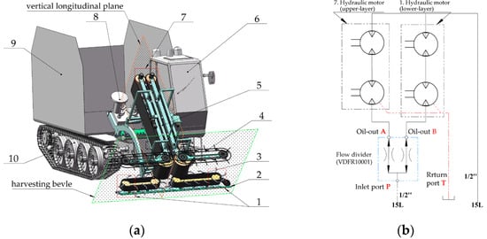
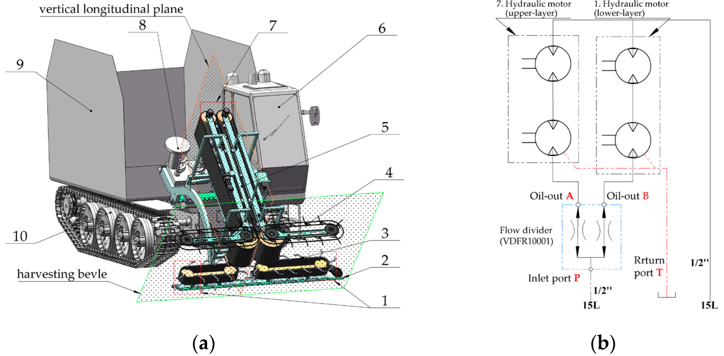
The integrated whole-stalk reed-harvesting and baling machine designed in this paper is primarily composed of a whole-stalk harvesting header, an automatic baler, a reed storage bin, and a self-propelled chassis (World, Zhenjiang, China). A three-dimensional model is shown in Figure 1a. The reed header further includes a cutter bar, bilateral transverse conveyors, and an upright clamping longitudinal conveyor, arranged in a T-shaped configuration. The inclination angle of the harvesting bevel where the transverse conveying chain is located is 35°. The drive sprocket of the upper transverse conveyor chain and the driven roller of the longitudinal clamping conveyor chain are coaxial and are driven by a set of hydraulic motors; the lower horizontal conveyor chain is driven by a separate set of hydraulic motors. The hydraulic schematic is shown in Figure 1b.
Figure 1.
Schematic diagram of the reed-harvesting and baling integrated machine (original): (a) structural schematic diagram of the header; (b) header conveyor system hydraulic schematic; 1. hydraulic motor (lower layer); 2. cutting device; 3. lower transverse conveyor chains; 4. upper transverse conveyor chains; 5. longitudinal conveyor chain; 6. cab; 7. hydraulic motor (upper layer); 8. automatic baler; 9. stock bin; 10. chassis.
During operation, the cutter bar cuts reeds at ground level. The transverse conveyors then gather cut stalks from both sides and move them toward the center; they converge in the process. When stalks reach the inlet of the longitudinal clamping conveyor, the following synergistic actions occur:
- Friction between conveyor belts and stalks;
- Assisted pushing by transverse conveyor fingers.
This propels stalks perpendicularly into the longitudinal conveyor. The efficiency and loss rate of the reed whole-stalk header during this process are calculated as shown in Equations (1) and (2).
—Harvesting efficiency;
—Cutting width;
—Header forward speed.
—Header loss rate;
—Header loss;
—Harvested reed.
To ensure the high efficiency and low loss rate of the T-shaped header when harvesting reeds, the header requires focused attention on parameter matching in the following four aspects:
- (1)
- When reeds are conveyed by the longitudinal conveying chain in the vertical longitudinal plane, their stalks should be kept as perpendicular as possible to the chain. This helps reduce conveying losses and facilitates baling. The posture of the reeds in the vertical longitudinal plane is primarily determined by the matching between the header’s forward speed and the longitudinal conveying chain speed at the chain’s inlet [12].
- (2)
- The harvesting bevel forms an inclination angle α = 35° with the ground, resulting in a time difference between the upper and lower transverse conveying chains when cutting into the reeds. As a result, the reeds lean toward the inlet within the harvesting bevel. To ensure that the reeds maintain a posture perpendicular to the longitudinal conveying chain at the inlet of the chain within the harvesting bevel, it is necessary to match the speeds of the upper and lower transverse conveying chains ( and ) to adjust the posture of the reeds, thereby reducing the header loss rate.
- (3)
- The header advances at speed , According to Equation (1), higher speeds result in greater efficiency. However, to ensure a low loss rate, the reeds cut by the header must be promptly conveyed by the transverse conveying chain to the inlet of the longitudinal conveying chain. The conveying capacity of the transverse conveying chain depends on its speed , the lugs’ height , and the reed planting density . Therefore, the header’s forward speed must be matched with the transverse conveying chain speed, picker height, and reed planting density [13].
- (4)
- At the inlet of the longitudinal conveying chain, to ensure reliable entry of the reeds, the roller diameter at the inlet must be matched based on the reed stalk diameter and the friction coefficient between the reed stalks and the conveyor belt [14].
When the key structural and kinematic parameters of the T-shaped whole-stalk reed header—such as forward speed, conveying chain speed, header inclination angle, lug height, and feeding roller diameter—operate in a properly matched mode, the whole-stalk reed header will maintain highly efficient performance [15]. Therefore, this paper analyzes the matching relationships among the key structural and kinematic parameters of the T-shaped whole-stalk reed header. Based on this analysis, general design criteria for the parameters of the whole-stalk reed header will be established, providing theoretical support for the design of headers for whole-stalk harvesting of tall crops such as reeds.
2.2. Analysis of Matching Key Structural and Kinematic Parameters of the Header
2.2.1. Analysis of Speed Matching Between Header Forward and Longitudinal Conveying Chain
In the vertical longitudinal plane, the ideal state for reeds conveyed by the longitudinal clamping conveyor chain is that the reed stalks remain perpendicular to the chain. If this perpendicular alignment is not maintained or significant angular deviation occurs, it can easily lead to losses during longitudinal clamping conveyance and reduce the baling efficiency in subsequent processes.
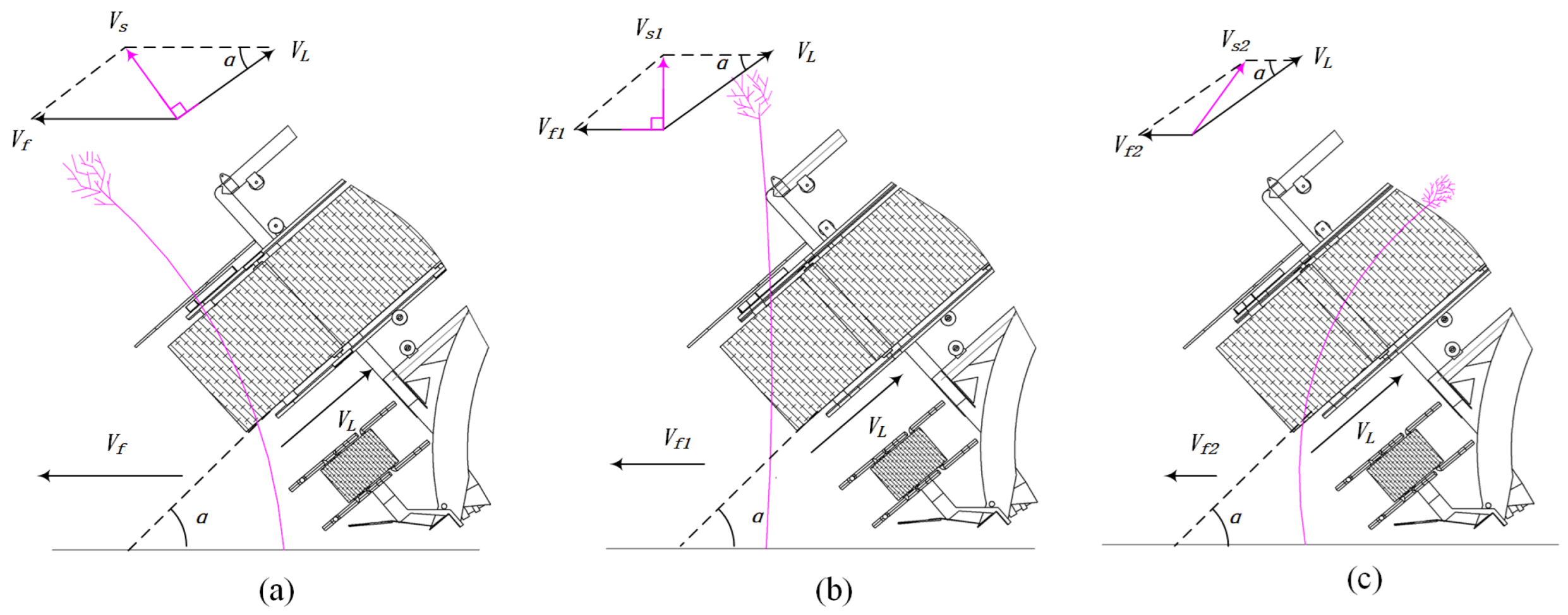
When the header tilt angle is α, the direction of the resultant velocity (composed of and ) at the central longitudinal chain feed inlet determines the entry behavior of reed stalks into the longitudinal conveyor chain [16]. Three primary operational cases exist:
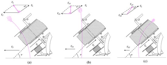
(1) When the direction of the resultant velocity is perpendicular to the longitudinal conveyor chain (Figure 2a), the reed stalks are conveyed into the longitudinal chain by the transverse chain lugs at an orientation perpendicular to the chain. This represents the optimal posture, resulting in the lowest header loss [17]. In this case,
Figure 2.
Behavior evolution of reeds in longitudinal conveyor chain (original): (a) the direction of the resultant velocity is perpendicular to the longitudinal conveyor chain; (b) the direction of the resultant velocity is perpendicular to the ground; (c) the directions of and are nearly identical.
(2) When the header forward speed decreases to Vf1, such that Vs1 becomes perpendicular to the ground (Figure 2b), the reed stalks are fed into the longitudinal chain by the transverse chain lugs in a vertical orientation relative to the ground. At this point, the loss rate increases. In this case,
(3) When the header forward speed further reduces to Vf2 or until the header stops (Vf2 → 0), the upper sections of reed stalks are pushed inward by the transverse chain lugs (Figure 2c). This causes most stalks to enter the longitudinal chain ear-first, resulting in an inwardly tilted conveyance orientation. In this case,
When reed stalks enter the longitudinal clamping conveyor chain in a vertical-to-ground or inwardly tilted orientation (Figure 2b,c), the chain clamps the upper section of the stalks. The diameter of the upper stalk section is typically 1–2 mm smaller than that of the lower section. Consequently, the clamping force exerted by the conveyor belt on the upper stalk section is significantly less than that on the lower section. Therefore, under the combined effects of stalk self-weight or traction from the root cleaning unit, reeds readily dislodge at the discharge end of the longitudinal conveyor chain.
Simultaneously, at the discharge end of the longitudinal clamping conveyor chain, an automatic baling mechanism gathers reeds into compact bales. This process requires reed stalks to enter the baling tines in an orientation perpendicular to the longitudinal chain to ensure reliable bale formation. Therefore, to reduce the header loss rate and achieve dependable baling, the header forward speed must be optimally controlled. The optimal value of the forward speed is determined by Equation (3). When the forward speed needs to be adjusted, its minimum value must satisfy Inequality (6):
2.2.2. Analysis of Speed Matching Between Upper/Lower-Layer Transverse Conveyor
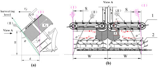
The header’s transverse conveyor within the harvesting bevel consists of upper and lower conveyor layers, Since there is a fixed inclination angle α between the harvesting bevel and the vertical plane, see Figure 3a. Due to the protrusion distance of the upper layer relative to the lower layer in the travel direction, when the header advances at speed , the upper layer contacts reeds first at Position I (Figure 3a). At this stage (highlighted in pink, with the header omitted for clarity), the following holds:
Figure 3.
Speed analysis of the upper and lower transverse conveyor chains (original): (a) parameters for vertical longitudinal plane; (b) parameters for transverse plane; 1. upper transverse conveyor chain; 2. lower transverse conveyor chain (pink reed- the posture of the reed in position I; black reed- the posture of the reed in position II; —header forward speed; —upper conveyor chain height; —protrusion distance; α—header tilt angle; —longitudinal conveyor chain speed; and —upper and lower transverse conveyor chain speed; —transverse displacement; α′—reed stalk tilt angle; —unilateral transverse conveying chain width).
- Reeds remain unrestrained.
- Reed tops are propelled toward the longitudinal conveyor inlet at velocity Vt-up by upper-layer fingers.
- Lower-layer contact is absent.
- Roots remain uncut.
Consequently, reeds tilt integrally toward the inlet.
At Position II, the following is true:
- Roots engage the cutter bar.
- Reeds attain inclination α on the vertical longitudinal plane (equal to the harvesting bevel inclination).
- Transverse displacement and inclination α′ of the reed stalk develop in the harvesting bevel (Figure 3b).
If no adjustment is made, the α′ prevents perpendicular alignment with the longitudinal conveyor upon entry. This misalignment increases the probability of stalk detachment and the header material loss rate during clamping conveyance.
To minimize the header loss rate, as the header reaches position II and reeds are cut at the roots by the cutter before being laterally conveyed along the header, the morphology of reed stalks can be adjusted through the speed differential between the upper and lower layers of the conveying chain. This adjustment shifts reed stalks toward a near-vertical orientation within the harvesting bevel, enabling them to enter the longitudinal conveying chain as perpendicularly as possible.
To achieve this objective, the speeds of the upper and lower transverse conveying chains, denoted as and , must satisfy the following condition:
The difference ΔV between Vt−low and Vt−up determines the degree to which inclined stalks on the header restore vertical orientation, thereby modulating the header loss rate [18]. Let S′ denote the final transverse displacement of reed stalks at the upper and lower transverse conveying chains when conveyed to the inlet of the longitudinal conveying chain. This value quantifies the resultant angular deviation from verticality as reeds enter the longitudinal conveying chain.
The value of t depends on the transverse conveying distance of reed stalks. For reeds at different positions—from the outermost edge of the transverse conveying chains to the central inlet—the transverse conveying time t varies from 0 to .
Consequently, the verticality deviation S′ of reed stalks at varying transverse positions on the header still differs after being conveyed by upper/lower transverse chains with velocity difference ΔV to the inlet of the longitudinal conveying chain. To minimize the integrated verticality deviation of reeds entering the longitudinal chain across all transverse positions, and subject to the constraint that , we obtain the following:
This implies that when the upper and lower transverse conveying chain speeds Vt−up and Vt−low satisfy Equation (10), the aggregate angular deviation of reed stalks is minimized upon entering the inlet of the longitudinal conveying chain. Consequently, the reed stalks enter the longitudinal pinching chain in a nearly vertical orientation. The drive sprocket of the upper transverse conveying chain shares a common shaft with the driven roller of the longitudinal conveying chain (Figure 3b). Therefore, the speed of the upper transverse conveying chain and the speed of the longitudinal conveying chain maintain a
constant ratio, as shown in Equation (11):
drive sprocket diameter (upper transverse conveying chain);
driven roller diameter (longitudinal conveying chain).
Therefore, in actual headers, is typically fixed, while —driven by an independent hydraulic motor—is adjusted to ensure that and meet the requirement specified in Equation (10).
2.2.3. Analysis of the Height of Transverse Conveyor Chain Lug Height
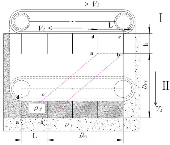
The upper and lower transverse conveyor chains are both equipped with lugs. The lug height is h, and the separation distance is L. The function of the lugs is to transversely push the cut reeds to the inlet of the longitudinal conveyor chain. As shown in Figure 4, it is assumed that at position (I), the transverse conveyor chain begins to cut into the reeds. After a time interval of Δt, the machine advances to position (II). The transverse displacement of the transverse conveyor chain lugs is Dvt, and the forward travel distance of the header is Dvf. During this period, the area harvested by adjacent lugs forms the quadrilateral abb′a′ [13]. The area of this quadrilateral Sabb′a′, is calculated as follows:
Figure 4.
Schematic diagram of transverse conveyor chain conveying reeds (original) (I—starting position of header entry into the reeds; II—position of header after cutting into reeds for Δt; —header forward speed; —transverse conveyor chain speed; —lug height; —lug spacing; —reed planting density; —reed density between lugs).
It is assumed that the reed planting density in front of the header is . Due to the header tilt angle, during the forward motion of the header, the deflection force generated by the bending of uncut reeds ahead of the header exerts compressive pressure on cut reeds between lugs. This forces reeds to accumulate between lugs, increasing their density (assumed as ). This accumulation effect facilitates the transverse transport of the reeds.
The reed area harvested per unit time by adjacent lugs in the transverse conveyor chain depends on the forward speed of the harvester. Higher forward speeds yield larger harvested areas per unit of time. However, since the lug height, “h”, is fixed, to ensure the smooth transport of cut reeds between lugs to the inlet of the header’s longitudinal conveyor chain and reduce the reed loss rate at the header, the accumulated reed volume between lugs must be lower than the maximum inter-lug capacity determined by the lug height. That is,
Since and , it follows
that
unilateral transverse conveying chain width;
header forward speed.
Since the transverse conveyor chain has upper and lower layers, with speeds of and respectively, according to Inequality (7), the selection is adopted herein. To ensure an optimal feed rate and minimize transverse conveyance loss at the header, the lug height is selected within the operating range of the header forward speed:
maximum forward speed of the header.
2.2.4. Analysis of Structural Parameters at the Longitudinal Conveying Chain Inlet
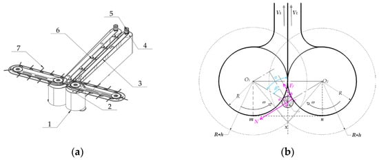
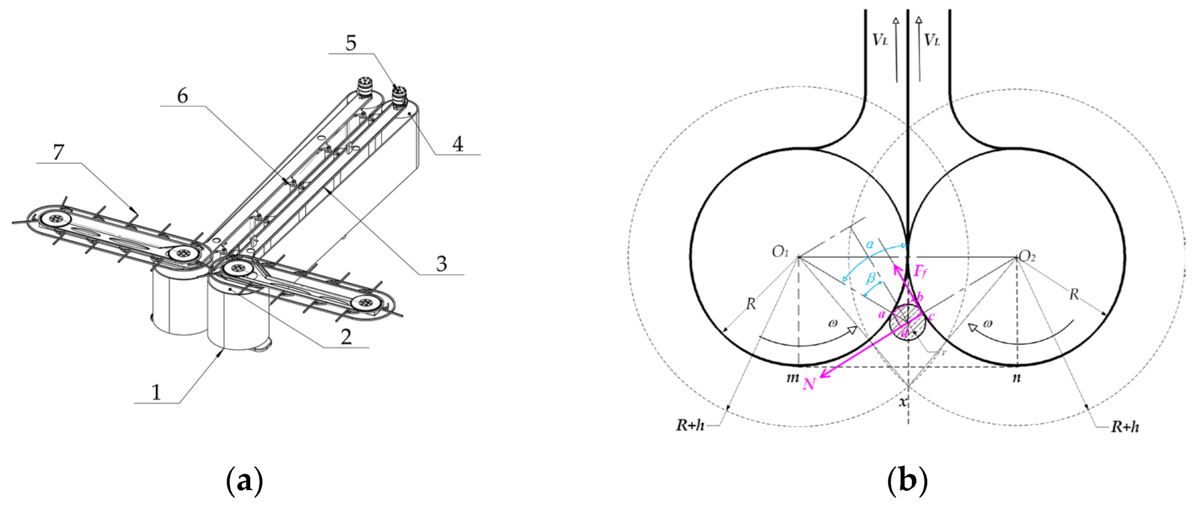
As illustrated in Figure 5a, the longitudinal conveying chain comprises dual-symmetrically arranged rubber belts with corresponding hydraulic motors, support frames, and idler rollers. The hydraulic motor drives the driving roller and, through the rubber clamping belt, drives the driven roller and the drive sprocket of the upper transverse conveyor chain coaxially with it. With the cooperation of the lower transverse conveyor chain, reed stalks are conveyed by the upper and lower transverse chains to the inlet of the longitudinal conveyor chain [19,20,21].
Figure 5.
Force analysis of reeds at the inlet of the longitudinal conveyor chain (original): (a) schematic diagram of the longitudinal conveying chain structure; (b) force analysis diagram of reed stalks at the feed inlet; 1. rubber conveyor belt; 2. driven roller; 3. conveyor frame; 4. drive roller; 5. hydraulic motor; 6. idler roller; 7. upper transverse conveyor chain.
At the longitudinal chain inlet, reed stalks are fed into the belts through frictional engagement between the rubber surfaces and stalks. The upper and lower lugs of the transverse conveying chain provide auxiliary propulsion for stalk entry. The stable and reliable feeding of reed stalks into the longitudinal pinching belts is critically determined by the driven roller diameter and the friction coefficient between the rubber belt and stalks [14].
As illustrated in Figure 5b, let the reed stalk radius be r and the driven roller radius be R. The friction coefficients f between reed stalks and rubber clamping belts were obtained through a pull and loading test [22], yielding a value of f = 0.6. When reeds enter the bilateral driven rollers at the feed inlet, consider the interaction between reeds and driven roller 2. For successful entry into the longitudinal clamping belts driven by friction force Ff, the moment generated by Ff relative to contact point a (with roller 1) must exceed the counter-moment produced by normal force N (with roller 2) about point a [23]; that is to say,
So, when we set the stalk radius as mm, we derive the driven roller radius as mm.
Simultaneously, to ensure the complete entry of reed stalks at the feed inlet of the longitudinal conveyor chain when pushed by the lugs of the transverse conveyor chains, the intersection point x of the maximum pushing ranges from the transverse chains on both sides must lie externally to the line connecting the tangent points m and n. That is, the distance between intersection point x and axis O1O2 must be greater than the driven roller radius R. That is,
So, we obtain Inequality (20):
2.3. Design Model for Key Structural and Kinematic Parameters of the Header
In this study, the basic structural and kinematic parameters of the integrated reed-harvesting and baling machine were determined based on reed characteristics sampled from the experimental site (Binhai Reed Farm, Sheyang County, Yancheng City, Jiangsu Province, China), as well as the requirements for header harvesting efficiency and the matching chassis. These parameters are summarized in Table 1.
Table 1.
Basic configuration and motion parameters of reed harvester–baler (original).
Based on the previous analysis of key kinematic and structural parameters, the design procedure for the key kinematic and structural parameters of the T-shaped reed whole-stalk harvesting header can be established as follows:
- (1)
- Based on the rated forward speed of the header and Equation (3), the longitudinal conveyor chain velocity is determined. During normal operation, generally remains constant. Based on the reed planting density and the Inequality (6), the value of is selected from the range where is the maximum forward speed of the header, determined by the chassis;
- (2)
- Since the driven roller of the longitudinal conveyor chain and the drive roller of the upper lateral conveyor chain are coaxial and fixed, the speed of the upper lateral conveyor chain can be determined based on the longitudinal conveyor chain speed using Equation (11). Then, using the forward speed and the corresponding structural parameters, the speed of the lower lateral conveyor chain can be determined by applying Equation (10);
- (3)
- Based on the maximum forward speed , the speed of the upper transverse conveyor chain , the reed planting density, and the width of the header, the height of the transverse conveyor chain lugs can subsequently be determined using Inequality (15);
- (4)
- Based on the height of the transverse conveyor chain lugs , the diameter of reed stalks, and the friction coefficient between the stalks and the belt, the diameter of the longitudinal conveyor chain feeding roller can be determined using Equation (18) and Inequality (20).
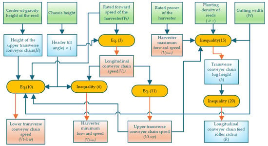
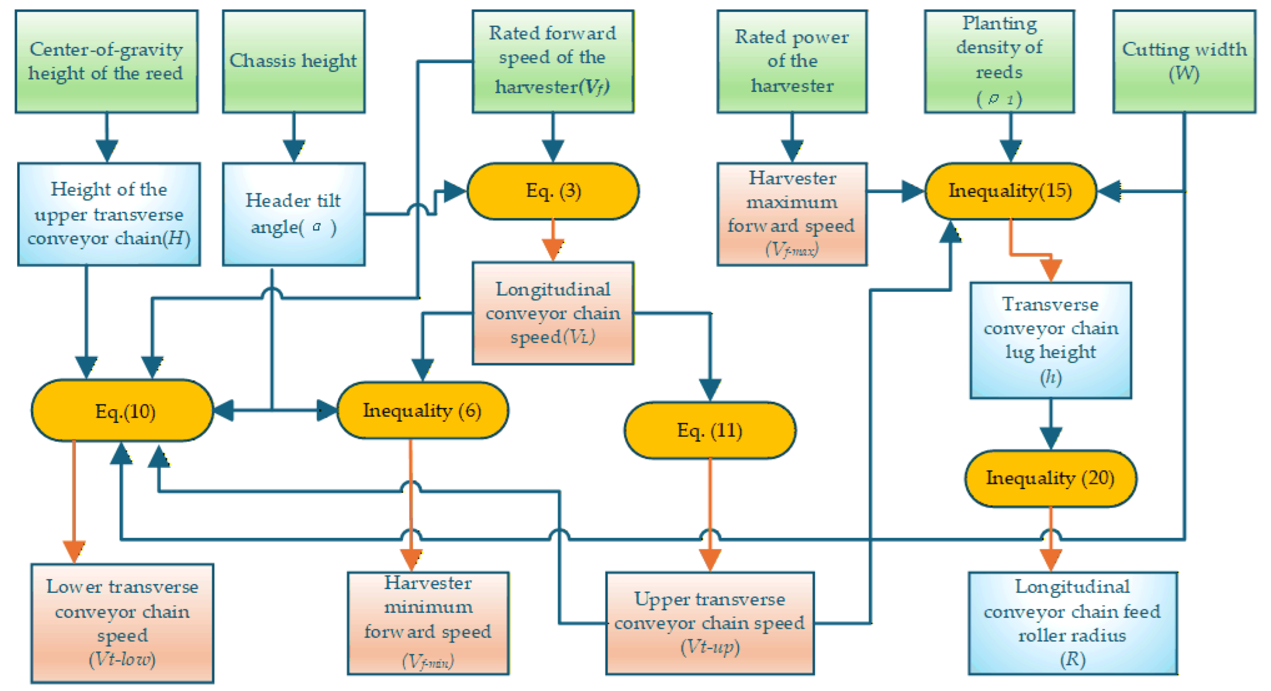
Building on the analysis of key kinematic and structural parameters of the whole-stalk reed-harvesting and baling header in the previous section, a design model for these parameters has been developed. This model is organized into the technical design flowchart shown in Figure 6. In the flowchart, the green boxes represent the reed characteristic parameters and the basic structural and kinematic parameters of the integrated reed-harvesting and baling machine; the orange ellipses represent the relational equations for key structural and kinematic parameters; and the blue and pink boxes represent the key structural and kinematic parameters of the header, determined based on the basic parameters and the relational equations, respectively. The specific values are listed in Table 2.
Figure 6.
Flowchart for determining key structural and kinematic parameters of t-type header in whole-stalk reed harvesting (original).
Table 2.
Core configuration and motion parameters of reed harvester–baler (original).
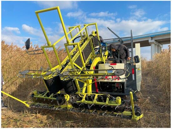
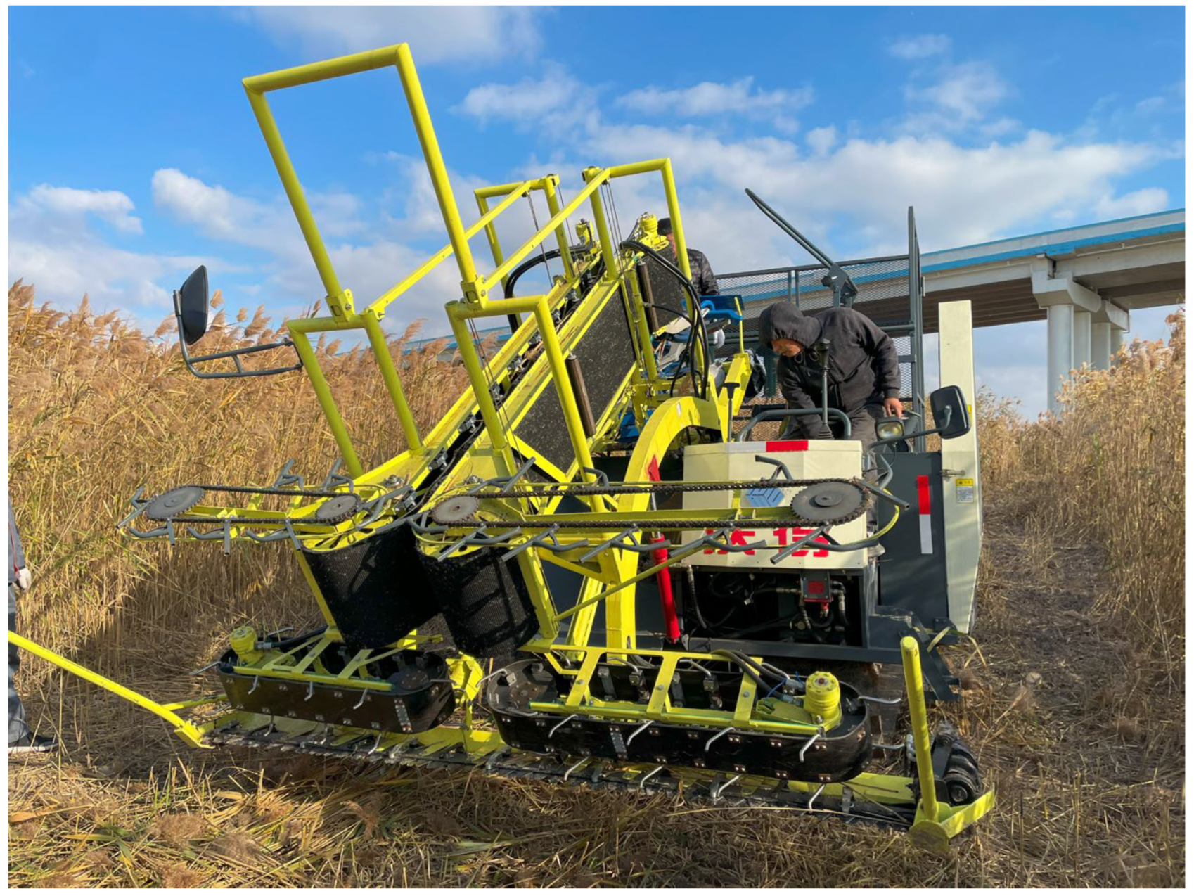
Based on the parameters listed in Table 1 and Table 2, the research team developed a 4WGK-2.8 integrated reed-harvesting and baling machine, as shown in Figure 7. For the harvester chassis, we adopted a crawler-type self-propelled design to accommodate the waterlogged and subsidence-prone ground conditions typical of reed fields. The integrated control system ensures the stable operation of both the chassis and the header conveying system at constant preset speeds [24].
Figure 7.
Integrated whole-stalk reed harvester–baler (original).
2.4. Experimental Design
The reed harvester was tested in November 2023 in Sheyang County, Yancheng City, Jiangsu Province, China (33°46′19.32″ N, 120°27′14.55″ E, at an altitude of 2.48 m).
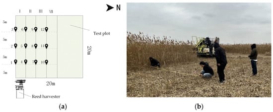
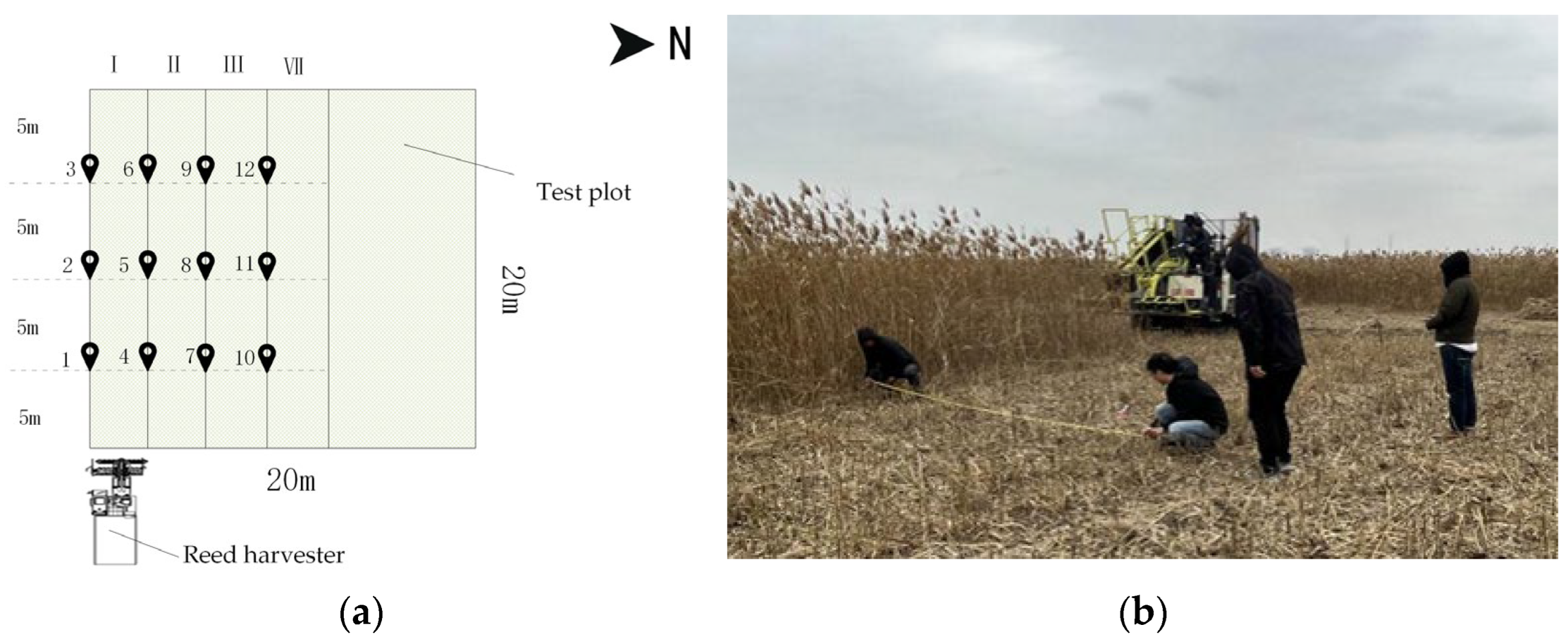
The reeds harvested were wild reeds from coastal mudflats, with an average plant height of 2.5 m, planting density of 80 stalks/m2, and stalk moisture content of 35% at harvest. A 20 m × 20 m square reed field with relatively flat terrain was selected for testing and the sinkage depth of the test field ranges from 15 to 50 mm. The weather was sunny during the harvest. Four harvesting runs were performed at different forward speeds. On the southern edge of each harvested plot, measurement points were established at 5 m intervals along an east-to-west transect. This ensured three measurements per harvest, resulting in a total of 12 measurements from the four harvests, as illustrated in Figure 8a.
Figure 8.
Cutting width measurement (original): (a) annotated layout plan of field test protocol; (b) manual measurement of cutting width.
This test primarily verified the following in the harvester:
- The actual cutting width and harvesting efficiency;
- The header loss rate and baling rate under varying forward speeds and transverse/longitudinal conveyor speeds [25].
3. Results
3.1. Cutting Width and Harvesting Capacity
The harvester operated at an average speed of 1 m/s. Upon completing one harvesting pass, the actual cutting width of the reed harvester was manually measured at the corresponding measurement points using a tape measure, as shown in Figure 8b. The measured cutting width data are summarized in Table 3.
Table 3.
Effective operating cutting width (original).
Analysis of variance (ANOVA) of the four sets of cutting width measurement data in Table 3 shows that there is no significant overall difference in actual cutting width among the groups (p = 0.07 > 0.05). Therefore, the mean value of the measured cutting width data, 2852.8 mm, was taken as the actual cutting width of the harvester. Based on the average speed of 1 m/s and using Equation (1), the average harvesting efficiency for reeds was calculated to be 1.0 hm2/h.
3.2. Header Loss Rate
According to the header transmission design, the longitudinal conveying chain and the upper transverse conveying chain are driven by the same hydraulic motor, with a fixed-ratio speed between them. Therefore, the speed changes in the longitudinal conveying chain and the upper transverse conveying chain are interconnected. During the experiment, the speeds of the longitudinal conveying chain and the upper transverse conveying chain were maintained at their rated values, while the header forward speed and the lower transverse conveying chain speed were used as variables. A two-round single-factor test was conducted to verify the correctness of the design model for the key structural and kinematic parameters of the header [26].
3.2.1. Effect of Header Forward Speed
In Test Run 1, the longitudinal conveyor chain speed, upper transverse conveyor chain speed, and lower transverse conveyor chain speed were kept constant at , , and , respectively.
Meanwhile, forward speeds of 0.3 m/s, 0.8 m/s, 1.0 m/s, and 1.4 m/s were tested during harvesting. At each measurement point, the harvested and baled reeds, as well as the reeds lost to the header and ground, were collected and weighed. The fresh weight of reeds was measured on-site using a spring scale (accuracy: ±10 g), and the header loss rate at each measurement point was calculated using Equation (2). The resulting loss rates for Run 1 are listed in Table 4.
Table 4.
Header loss rate statistics (variable: forward speed Vf) (original).
Analysis of variance (ANOVA) performed on the four sets of header loss rate (Lh) data obtained under different forward speeds in Table 4 reveals a significant difference among the groups (p = 2.3 × 10⁻¹² < 0.05). This indicates that, while the speeds of the longitudinal conveying chain, the upper transverse conveying chain, and the lower lateral conveying chain were held constant, variations in the forward speed had a significant impact on the header loss rate.
3.2.2. Effect of Header Transverse Conveyor Speed
In Test Run 2, the upper transverse conveyor chain speed was kept constant at , and the longitudinal conveyor chain speed was maintained at . Throughout the test, while keeping the forward speed constant at , the rotational speed of the lower transverse conveyor hydraulic motor was varied to achieve lower transverse conveyor speeds of , , , and during harvesting. The header loss rates at each measurement point were calculated using the same methodology. The header loss rates at each measurement point for Test Run 2 are presented in Table 5.
Table 5.
Header loss rate statistics (variable: lower transverse conveyor speed ) (original).
Analysis of variance (ANOVA) performed on the four sets of header loss rate (Lh) data obtained under different lower lateral conveying chain speeds in Table 5 also shows a significant difference among the groups (p = 5.0 × 10⁻⁵ < 0.05). This indicates that, while the speeds of the longitudinal conveying chain, the upper transverse conveying chain, and the forward speed of the header were held constant, variations in the lower transverse conveying chain speed also had a significant impact on the header loss rate.
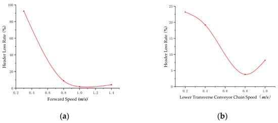
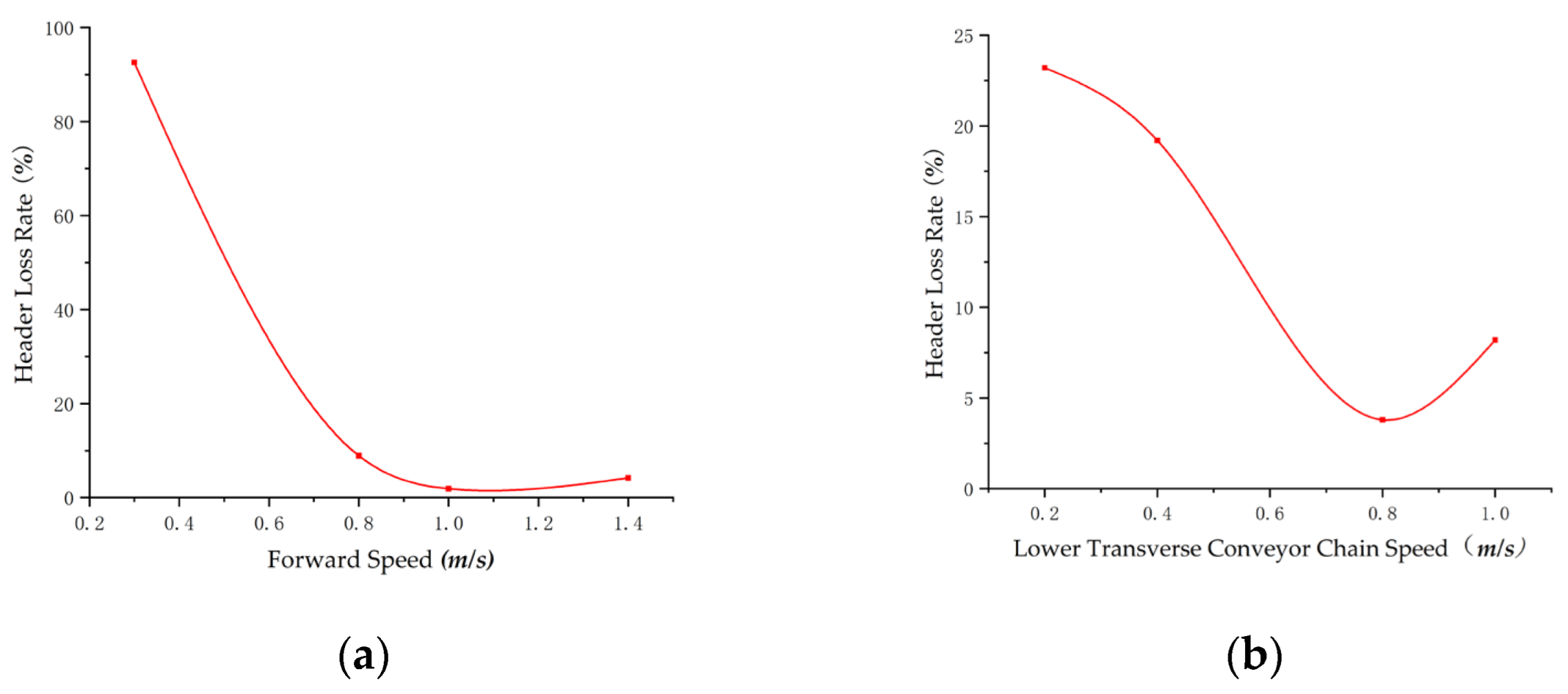
The relationship curves for the header loss rate versus the forward speed and lower transverse conveyor speed, derived from two single-factor test runs, are plotted in Figure 9.
Figure 9.
Header loss rate variation curve (original): (a) relationship curves for header loss rate versus forward speed; (b) relationship curves for header loss rate versus lower transverse conveyor speed.
Analysis of Figure 9a reveals that when the longitudinal and upper transverse conveyor speeds are constant, the forward speed exhibited a strong negative correlation with the header loss rate (r = −0.85). At lower forward speeds (<0.8 m/s), the resultant velocity vector of longitudinal conveyor speed and forward speed deviates from perpendicularity to the conveyor chain. This causes reeds to enter the longitudinal conveyor at oblique angles, leading to the following two failure modes:
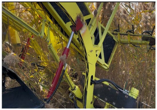
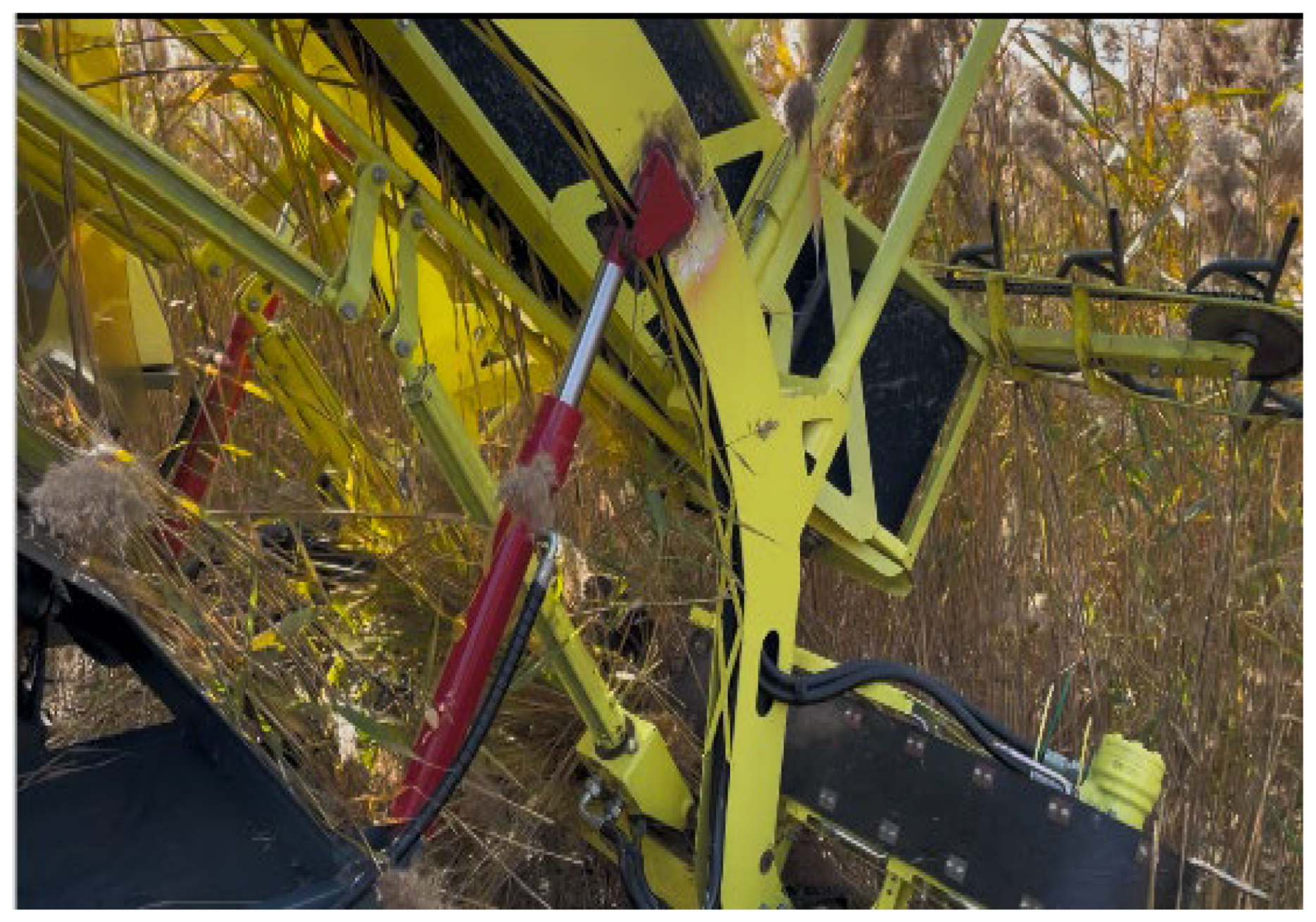
- Most reeds drop at the conveyor exit due to unstable conveyance (Figure 10).
- Oblique reed orientation hinders effective baling machine gathering.
Figure 10.
Reed loss on longitudinal conveyor chain (original).
Consequently, the header loss rates increase substantially.
At a 1.0 m/s forward speed, the resultant velocity vector becomes nearly perpendicular to the conveyor chain, minimizing reed drop at the conveyor exit and baling interface. This achieves the minimum header loss rate.
Beyond 1.0 m/s, the reed accumulation between pickup fingers exceeds the maximum transport capacity determined by the transverse conveyor speed and lug height. This causes increased losses at the transverse conveyor, thereby elevating the header loss rate.
Figure 9b demonstrates that under constant upper transverse conveyor speed and forward speed. The lower transverse conveying chain speed also exhibited a strong negative correlation with the header loss rate (r = −0.91). This primarily occurs because mismatched speeds between the upper and lower transverse chains increase the overall deviation from perpendicularity when reeds are conveyed to the longitudinal conveyor feed inlet, thereby elevating the header loss rate.
As shown in Figure 9b, when the lower transverse conveyor speed is 0.8 m/s and the upper transverse speed is 0.4 m/s—satisfying Equation (10)—reeds achieve minimal overall perpendicularity deviation at longitudinal conveyor entry. Consequently, the header loss rate reaches its lowest value.
Comparative analysis of Figure 9a,b reveals that under equivalent speed variation magnitudes, the forward speed has a more pronounced impact on the header loss rate in T-shaped reed whole-stalk harvesters than transverse conveyor speed variations. Consequently, maintaining precise control of forward speed is essential during whole-stalk harvesting operations.
4. Discussion
In the T-shaped header formed by the combination of bilateral transverse conveying and longitudinal clamping conveying, the posture of reeds in the conveying chain significantly affects the efficiency of whole-stalk reed harvesting and real-time baling. Reeds should be conveyed in the chains with a posture as perpendicular as possible to both the transverse and longitudinal conveying chains. To ensure the proper posture of reeds in the conveying chains, key structural and kinematic parameters—such as the speed difference between the upper and lower transverse conveying chains, the speeds of the longitudinal clamping conveying chain and the harvester forward motion, the height of the lifting lugs on the transverse conveying chains, and the diameter of the rollers at the entrance of the longitudinal conveying chain—must be matched according to the design criteria derived from the analysis presented in this paper.
The T-shaped header increases the cutting width through the configuration of bilateral transverse conveying chains. The effective combination of the longitudinal conveying chain and the baler at its end enables real-time baling of reeds within the header. As a result, the efficiency of the T-shaped header in harvesting reeds is significantly improved. A comparison of its performance parameters with similar reed harvesters domestically and internationally is presented in Table 6.
Table 6.
Comparative Analysis of Key Performance Parameters of Several Typical Reed Harvesters.
As can be seen from the comparative data, the reed harvesting and baling combine equipped with the T-shaped header achieves an efficiency increase of 40% to 100% compared to other typical models. Furthermore, this machine can also perform real-time baling, which facilitates the subsequent collection of reeds.
During the experiments in this paper, test areas with relatively uniform reed planting density were selected to more accurately reflect the impact of the harvester’s forward speed and the transversal/longitudinal conveying speeds of the header on the header loss rate. However, under actual wild conditions, reed planting density varies significantly. Therefore, the forward speed of the header generally needs to be adjusted in real time according to density variations. This can be achieved through manual control or by employing an automatic control system capable of identifying pre-cut reed density to regulate the forward speed, thereby maintaining harvesting efficiency at a stable level. On the other hand, the whole-stalk harvesting method of the T-shaped header is not sensitive to the moisture content of reeds, meaning that changes in moisture content have a limited impact on harvesting efficiency. However, variations in the harvesting terrain—such as irregular plot shapes or soft soil with poor trafficability—can affect the harvester’s forward speed and consequently reduce harvesting efficiency. These issues represent key tasks for future research on the T-shaped whole-stalk harvesting header.
5. Conclusions
(1) Based on reed posture requirements during whole-stalk harvesting and real-time baling, an analysis was performed on the correlation between key structural and kinematic parameters of the T-shaped header with dual-layer transverse conveying and longitudinal clamping. This analysis yielded a technical workflow for determining the optimal parameters when harvesting high-stalk crops such as reeds.
(2) Prototype tests with typical parameters demonstrated that under constant longitudinal and upper transverse conveyor speeds, variations in header forward speed and lower transverse conveyor speed significantly alter reed stalk conveyance posture, thereby affecting the header loss rate and baling rate. To keep loss rates below 2.0% and baling rates above 95%, the structural and kinematic parameters must satisfy the relational equations derived in this study. Under these typical parameters, the T-shaped integrated reed-harvesting and baling header with a dual-layer transverse conveying and longitudinal clamping system proves to be feasible for efficient whole-stalk reed harvesting and baling. The average harvesting efficiency can reach 1 hm2/h.
(3) Based on the analysis results presented in this study, a virtual prototype model of the reed header and a biomechanical reed model can be further developed to simulate the interaction between the header and reeds during harvesting. This will enable a more comprehensive and in-depth understanding of the operational process of the T-shaped header in whole-stalk reed harvesting. This approach will provide valuable insights and guidance for the design of headers for reeds or similar tall crops.
Author Contributions
Conceptualization, B.J. and Y.L.; methodology, B.J.; validation, J.Z.; investigation, K.J.; resources, Y.L.; data curation, K.J. and B.F.; writing—original draft preparation, B.J.; writing—review and editing, J.Z. and K.J.; visualization, B.F.; project administration, Y.L.; funding acquisition, Y.L. All authors have read and agreed to the published version of the manuscript.
Funding
This research was funded by the 2019 Jiangsu Provincial Science and Technology Program Projects (Key Projects) (Jiangsu Provincial Department of Science and Technology, China; Grant No. BE2019360).
Institutional Review Board Statement
Not applicable.
Informed Consent Statement
Not applicable.
Data Availability Statement
All data are presented in this article in the form of figures and tables.
Conflicts of Interest
The authors declare no conflicts of interest.
References
- Kask, Ü.; Miljan, J. Guidebook of Reed Business; Salibar OÜ: Tartu, Estonia, 2013; ISBN 978-9949-484-91-1. [Google Scholar]
- Li, Z.Z. Overview of Recent Development of Non Wood Fibers Pulping in China. China Pulp Pap. 2011, 30, 55–63. [Google Scholar]
- Bentini, M.; Martelli, R. Giant Reed (Arundo donax L.) Harvesting System, an Economic and Technical Evaluation. J. Agric. Eng. 2013, 44, e120. [Google Scholar] [CrossRef]
- Tang, Z.; Li, Y.; Cheng, C. Development of Multi-Functional Combine Harvester with Grain Harvesting and Straw Baling. Span. J. Agric. Res. 2017, 15, e0202. [Google Scholar] [CrossRef] [Scilit]
- Nolan, A.; Mc Donnell, K.; Mc Siurtain, M.; Carroll, J.P.; Finnan, J.; Rice, B. Conservation of Miscanthus in Bale Form. Biosyst. Eng. 2009, 104, 345–352. [Google Scholar] [CrossRef] [Scilit]
- Zaica, A.; Paun, A. General Considerations on Reed Harvesting Machine from Wetlands Suitable for Its Growing. J. Agric. Eng. 2018, 44, 607–609. [Google Scholar] [CrossRef] [Scilit]
- Sally, M. Wetland Conservation Biomass to Bioenergy End User Report. Available online: https://ecosystemsknowledge.net/sites/default/files/wp-content/uploads/DECC%20Biomass%20to%20Bioenergy%20End%20User%20Report_0.pdf (accessed on 8 August 2025).
- Liao, Q.; Tian, B.; Shu, C. Research on Type 4ZG-2.1 Arundo Donaxl Harvester. Trans. Chin. Soc. Agric. Mach. 2007, 38, 86–89. [Google Scholar]
- Huang, J.; Tian, K.; Shen, C. Design and parameters optimization for cutting-conveying mechanism of ramie combine harvester. IJABE Int. J. Agric. Biol. Eng. 2020, 13, 94–103. [Google Scholar] [CrossRef] [Scilit]
- Bai, J.; Ma, S.; Cheng, C. The Lifting Performance and Experimental Study of a Variable Spiral Spike-Toothed Crop Divider. Agriculture 2024, 14, 916. [Google Scholar] [CrossRef] [Scilit]
- Reed and Jute Harvester. Available online: http://sdycyt.51sole.com/companyproductdetail_23662726.htm (accessed on 22 July 2025).
- Han, D.; Zhang, H.; Li, G. Development of a Bionic Picking Device for High Harvest and Low Loss Rate Pod Pepper Harvesting and Related Working Parameter Optimization Details. Agriculture 2024, 14, 859. [Google Scholar] [CrossRef] [Scilit]
- Liu, L. Studies on the Traverse Conveyor for the Forwardly Inclined Straw. Master’s Thesis, Northeast Agricultural University, Harbin, China, 2000. [Google Scholar]
- Li, B. Design Principles of Core Components in Corn Harvesters. In Agricultural Machinery Science; China Agriculture Press: Beijing, China, 2018; pp. 460–462. [Google Scholar]
- Wang, H.; Cao, S.; Xu, X.; Han, T.; Guo, H. Design of Mathematical Model of Main Working Parts of Grain Combine Harvester. J. Phys. Conf. Ser. 2019, 1213, 042074. [Google Scholar] [CrossRef] [Scilit]
- Wang, Q.; Yu, Z.; Zhang, Y. Experimental Study of a 4HLB-4 Half-Feed Four-Row Peanut Combine Harvester. Agronomy 2022, 12, 3094. [Google Scholar] [CrossRef] [Scilit]
- Yu, J.; Dong, X.; Chu, J. Design and Testing of a Bionic Flexible Low-Damage Tobacco-Leaf Harvesting Mechanism. Braz. J. Agric. Environ. Eng. 2025, 29, e292952. [Google Scholar] [CrossRef] [Scilit]
- Ji, K.; Li, Y. Device and Method Suitable for Matching and Adjusting Reel Speed and Forward Speed of Multi-Crop Harvesting. Agriculture 2022, 12, 213. [Google Scholar] [CrossRef] [Scilit]
- Liu, Z.; Wang, E.; Mao, H.; Zuo, Z. Design and Testing of an Electric Side-Mounted Cabbage Harvester. Agriculture 2024, 14, 1741. [Google Scholar] [CrossRef] [Scilit]
- Jin, Y.; Wang, J.; Chen, J. Design and Experiment for Flexible Clamping and Conveying Device for Green Leafy Vegetable Orderly Harvester. Agriculture 2024, 14, 967. [Google Scholar] [CrossRef] [Scilit]
- Liu, Z.; Mao, H.; Wang, Y.; Jiang, T. Design and Experiment of a Universal Harvesting Platform for Cabbage and Chinese Cabbage. Agriculture 2025, 15, 935. [Google Scholar] [CrossRef] [Scilit]
- Li, Z.; Li, P.; Liu, J. Physical and Mechanical Properties of Tomato Fruits as Related to Robot’s Harvesting. J. Food Eng. 2011, 103, 170–178. [Google Scholar] [CrossRef] [Scilit]
- Qiu, S.; Li, K.; Cui, Q.; Tang, Z. Design and Experimentation of the Millet Combine Harvester Header. Machines 2024, 12, 636. [Google Scholar] [CrossRef] [Scilit]
- Jiang, Y.; Wang, R.; Ding, R.; Sun, Z.; Jiang, Y.; Liu, W. Research Review of Agricultural Machinery Power Chassis in Hilly and Mountainous Areas. Agriculture 2025, 15, 1158. [Google Scholar] [CrossRef] [Scilit]
- Xiong, D.; Wu, M.; Xie, W.; Luo, H. Design and Experimental Study of the Key Components of a Rape (Brassica campestris) Shoots (Changxiangtai 603) Flexible Clamping Harvester. Agriculture 2023, 13, 792. [Google Scholar] [CrossRef] [Scilit]
- Wang, B.; Hu, Z.; Wu, F.; Gu, F. Analysis and Evaluation of Harvest Quality Effectiveness of Carrot Clamping and Conveying Device. Agriculture 2025, 15, 275. [Google Scholar] [CrossRef] [Scilit]

Disclaimer/Publisher’s Note: The statements, opinions and data contained in all publications are solely those of the individual author(s) and contributor(s) and not of MDPI and/or the editor(s). MDPI and/or the editor(s) disclaim responsibility for any injury to people or property resulting from any ideas, methods, instructions or products referred to in the content. |
© 2026 by the authors. Licensee MDPI, Basel, Switzerland. This article is an open access article distributed under the terms and conditions of the Creative Commons Attribution (CC BY) license.