


Abstract
This study introduces a deterministic framework for optimising the path planning of autonomous drill rigs in open-pit mining operations. While prior research has primarily focused on automating drilling mechanics, this study addresses the essential but underexplored phase of tramming, defined as the rig’s non-productive movement between holes. The proposed approach integrates geometric pattern recognition and slope-based route alignment. It also incorporates practical maneuverability constraints to generate efficient, smooth, and safe paths. Unlike evolutionary algorithms, which suffer from variability and demand extensive computation, this method delivers fast and consistent results. These are well-suited to the dynamic conditions of real-world mining. Applied to a 1596-hole case study, the framework reduced tramming time by over 50%, shortening the total project duration by 8% compared with the actual project. The findings demonstrate its potential to improve both operational efficiency and commercial readiness for autonomous drilling systems.
1. Introduction
The mining industry seeks to reduce costs, expand capacity, and increase profitability through autonomous technologies. Advances in robotics, AI, and precision sensors enhance efficiency, safety, and environmental monitoring. These also help address labour shortages and declining ore grades [1,2,3].
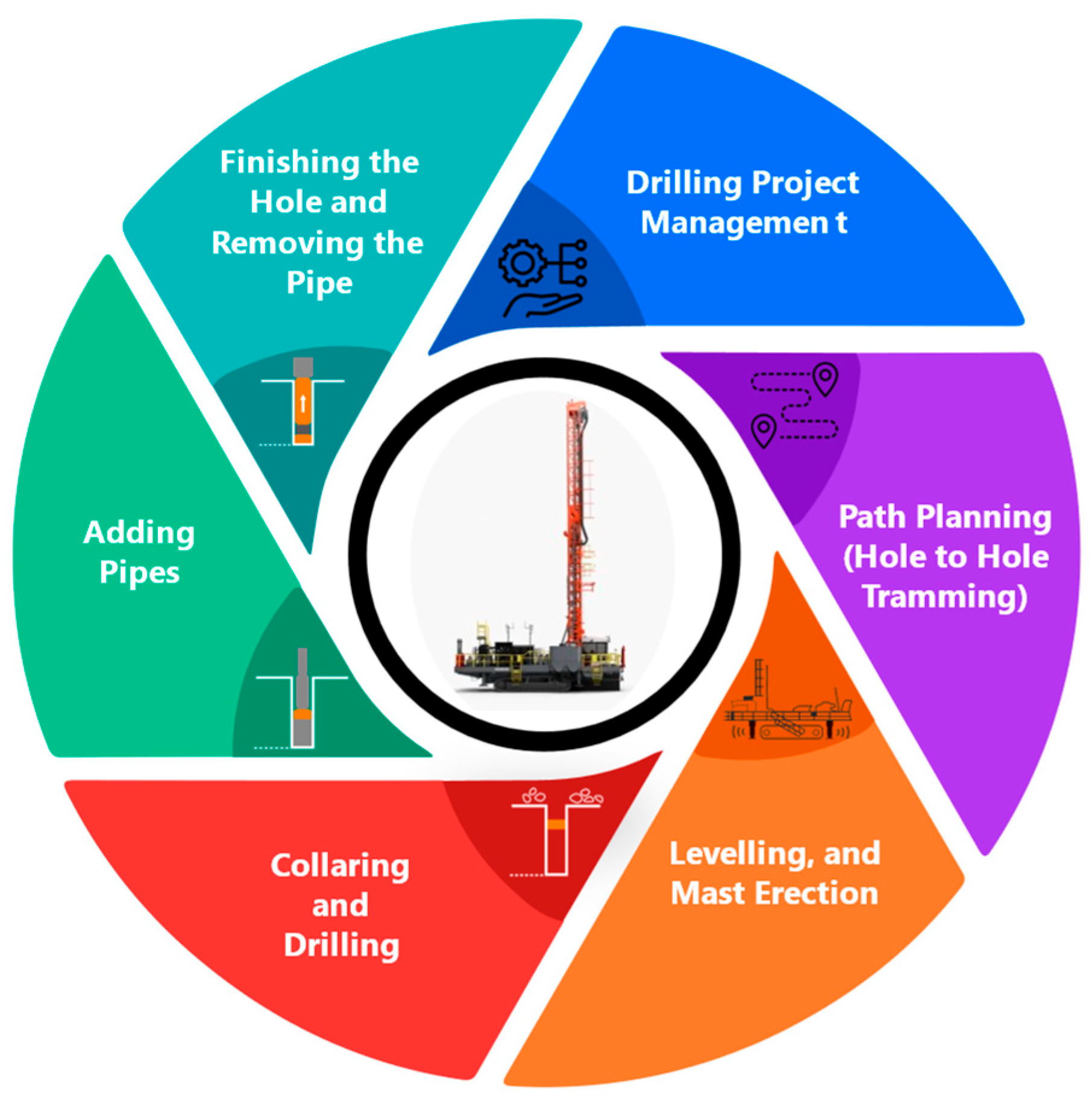
Drilling serves as the initial step in the mining production chain. The effectiveness of drilling activities and the skill of drilling teams directly affect operational success and increase costs in downstream processes [4,5]. In recent years, automating the drilling process has garnered significant interest as part of the broader goal of automating the entire mining workflow to boost the efficiency and productivity of the mining value chain [6]. However, most efforts by Original Equipment Manufacturers (OEMs) and research studies have mainly focused on hole drilling operations themselves. They have neglected other essential, time-consuming, and costly aspects such as operation management and drill path planning. Figure 1 illustrates the full cycle of a drilling project. It depicts the end-to-end workflow of a drilling operation, tailored for autonomous or semi-autonomous rigs, and divided into six sequential stages. The process starts with Drilling Project Management, where holes are allocated among rigs. This step establishes the foundation for operational efficiency. Next is Path Planning (Hole-to-Hole Tramming). This is essential for autonomous rigs to identify optimal routes between holes, thereby reducing idle time and enhancing productivity. Once a rig arrives at its first location, Levelling and Mast Erection is performed; the mast is typically raised only once, but levelling is repeated at each hole based on ground conditions. The rig then proceeds with Collaring and Drilling, initiating the hole and ensuring proper alignment. As drilling progresses, Pipes are added to reach the required depth. Finally, the operation concludes with Finishing the Hole and Removing the Pipe, after which the rig moves on to the next location to repeat the cycle. Each stage contributes to the overall efficiency, safety, and automation of the drilling process. Drill rig automation can be categorised into three main parts: levelling, drilling, and tramming [7]. While levelling and drilling have garnered attention from academia and industry in recent years, tramming has received limited focus.
Figure 1.
Open-pit drill rig operation cycle, with blue sections representing automated processes and black sections indicating non-automated processes.
Efficient management of drilling operations leads to shorter tramming distances and reduced project durations. Reducing the distance travelled lowers rig operating costs, including those for fuel, maintenance, servicing, equipment wear, and CO2 emissions. Faster completion of drilling tasks also reduces labour costs for rig operators and maintenance crews. Additionally, quicker drilling progress accelerates the start of subsequent stages, allowing companies to reach profitability faster—a key advantage in the competitive mining industry. Therefore, the project management and path planning for open-pit drill rigs can be defined as follows: drilling project management involves selecting the most suitable rigs for a project, dividing a drilling pattern between rigs, and adjusting in response to unforeseen circumstances, all while aiming to achieve optimal performance in terms of time and cost. Path planning and optimisation for rigs covers determining the optimum route from the first to the last holes of a drilling pattern, while the routes taken for a rig or a group of rigs are optimal with respect to distance and time.
This paper presents a state-of-the-art solution for drill rig path planning, targeting optimised rig management by enhancing manoeuvrability, minimising modelling time, and reducing tramming distance to shorten overall project duration. The approach focuses on determining the most efficient travel routes while addressing rig movement constraints. The following sections outline the literature review, data acquisition and analysis, methodology employed, results obtained, and the discussion, followed by conclusions and suggestions for future research.
Literature Review
A systematic literature review was conducted by the authors, examining path planning approaches for open-pit and underground mining equipment fleets [8]. Commercial autonomous drilling systems from major OEMs have advanced levelling and drilling automation. However, they do not yet include automated path planning for tramming between holes, despite claims of ‘full autonomy’ in marketing materials. The absence of technical publications from the industry limits direct comparison. In contrast, academic research on path planning for autonomous mining equipment has grown significantly in recent years, with a primary focus on continuously moving vehicles, such as haul trucks and loaders, in dynamic environments. However, these approaches are not directly transferable to blast-hole drill rigs due to fundamental differences. Drill rigs require complete coverage of fixed, discrete hole positions with minimal redundancy. They are subject to strict manoeuvrability and sequencing constraints, unlike methods focused on obstacle avoidance or real-time rerouting around moving assets.
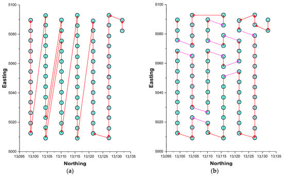
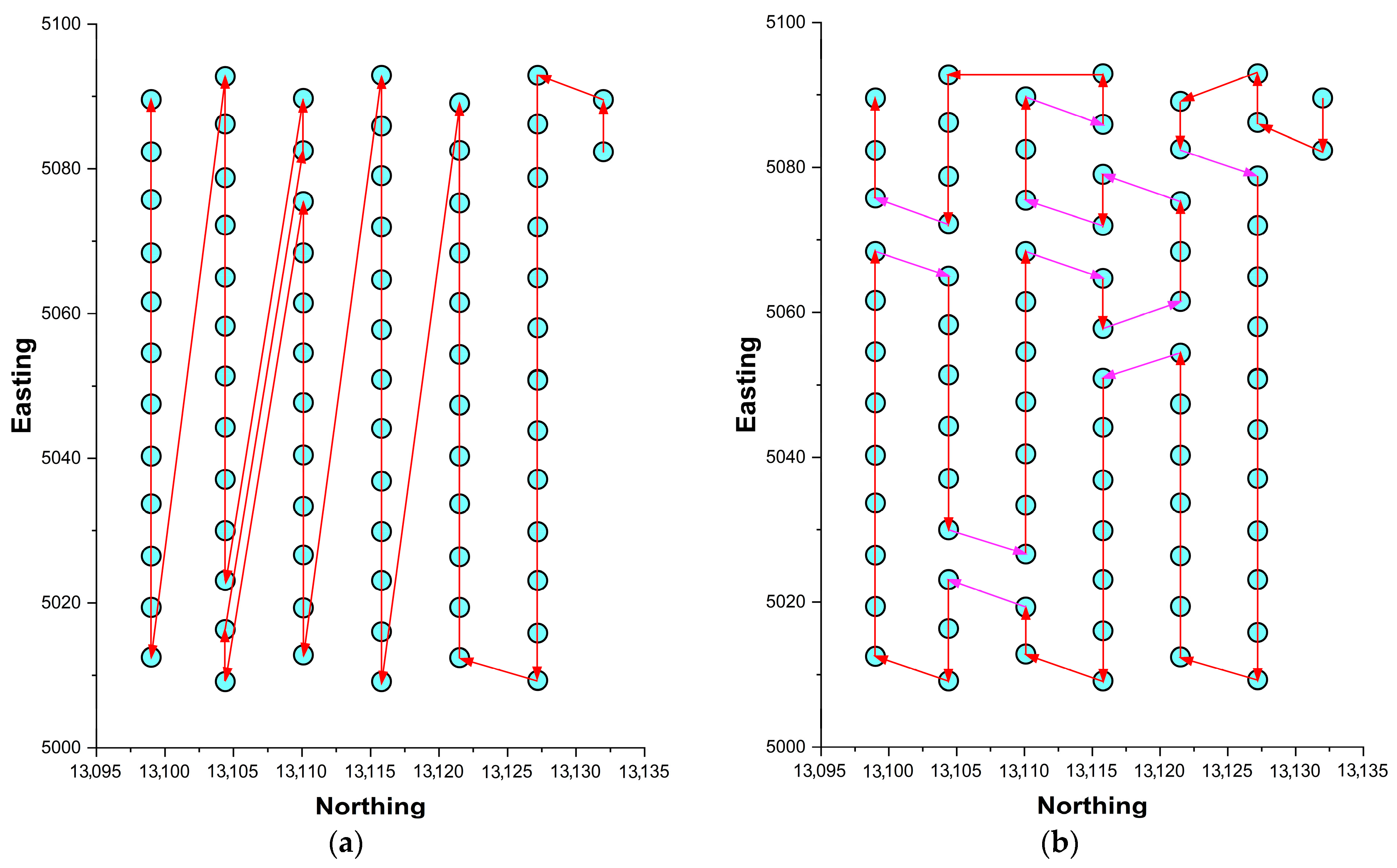
Only two highly relevant studies specifically addressing drill rig path planning were identified. In the first study, Elinas [9] highlighted that reliance on human judgment in drilling management can result in significant resource waste. The study revealed notable inefficiencies by analysing the path taken by an operator to drill 77 holes. The problem was modelled as a variation of the Travelling Salesman Problem (TSP) [10] and was solved using the Genetic Algorithm (GA). Figure 2a shows the operator’s original path, while Figure 2b displays the optimised path generated by the GA solver, reducing tramming distance from nearly 1450 m to approximately 825 m, resulting in a 43.1% reduction, as compared to the original pattern.
Figure 2.
(a) Original drilling pattern. (b) Optimised path generated by the solver. Modified from Elinas (2009) [9].
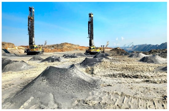
The study by Elinas [9] reveals several limitations. First, the modelling process omits rig manoeuvrability, as indicated by the unnecessary turnings (shown in purple in Figure 2b). Although rigs can turn in place, neglecting manoeuvring delays fails to account for operational inefficiencies. Additionally, rig movements during turning could displace surface debris, as illustrated in Figure 3, into drilled holes, potentially necessitating redrilling and increasing project duration and costs. Another limitation is the chosen approach: treating the issue as a standard TSP instance without simplifications resulted in excessive computational time for the optimal solution, even for a simple pattern of 77 holes. Elinas reported about 27 min for modelling and 5 min for path rendering. This is consistent with the known exponential increase in computational time with the number of nodes in TSP problems (Hoos and Stützle [11]).
Figure 3.
Drilling rigs in operation, with rock debris from earlier drilled holes visible on the ground surface [12].
A year after Elinas [9], another similar study was published by Fan et al. [7], which can be regarded as a complementary step towards developing a fully autonomous drill rig. Both studies were supported by the Rio Tinto Centre for Mine Automation and the Australian Centre for Field Robotics at the University of Sydney. In the study conducted by Fan et al. [7], they did not search for the optimum route; instead, the main objective was to develop a system for controlling the speed, yaw rate, and the position of the rig to drill holes from the starting point to the last point, while assuming that the order of holes was optimised previously. This study was developed for a single-rig motion control using the State Lattices method. However, there are some drawbacks that can be mentioned for this method. The first one is the non-optimality of the method used for large-scale problems, similar to the study by Elinas [9]. Precomputing motion primitives, especially in higher-dimensional state spaces, e.g., x and y (vehicle’s position coordinates), θ (heading angle), and v (linear velocity), can be resource-intensive. This is due to the complexity involved in generating and storing a comprehensive set of feasible trajectories that adhere to the system’s dynamics [13]. Moreover, Static Lattice structures may not adapt well to complex or dynamic environments without online adjustments. In rapidly changing scenarios, the precomputed motion primitives might not suffice, necessitating adaptive mechanisms [14]. Furthermore, the current study’s authors believe that speed and steering control are not major concerns in the automation of the drill rig, as these rigs are inherently slow vehicles that can turn at high angles within very short distances. Instead, aspects such as the drilling sequence of the holes in a pattern, the allocation of holes among available rigs, the selection of the most suitable rig for a drilling project, and safety controls when rigs pass each other or are near highwalls and free faces are of greater importance. Each of these parameters can significantly influence the economics of drilling projects and subsequent mining operations.
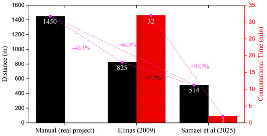
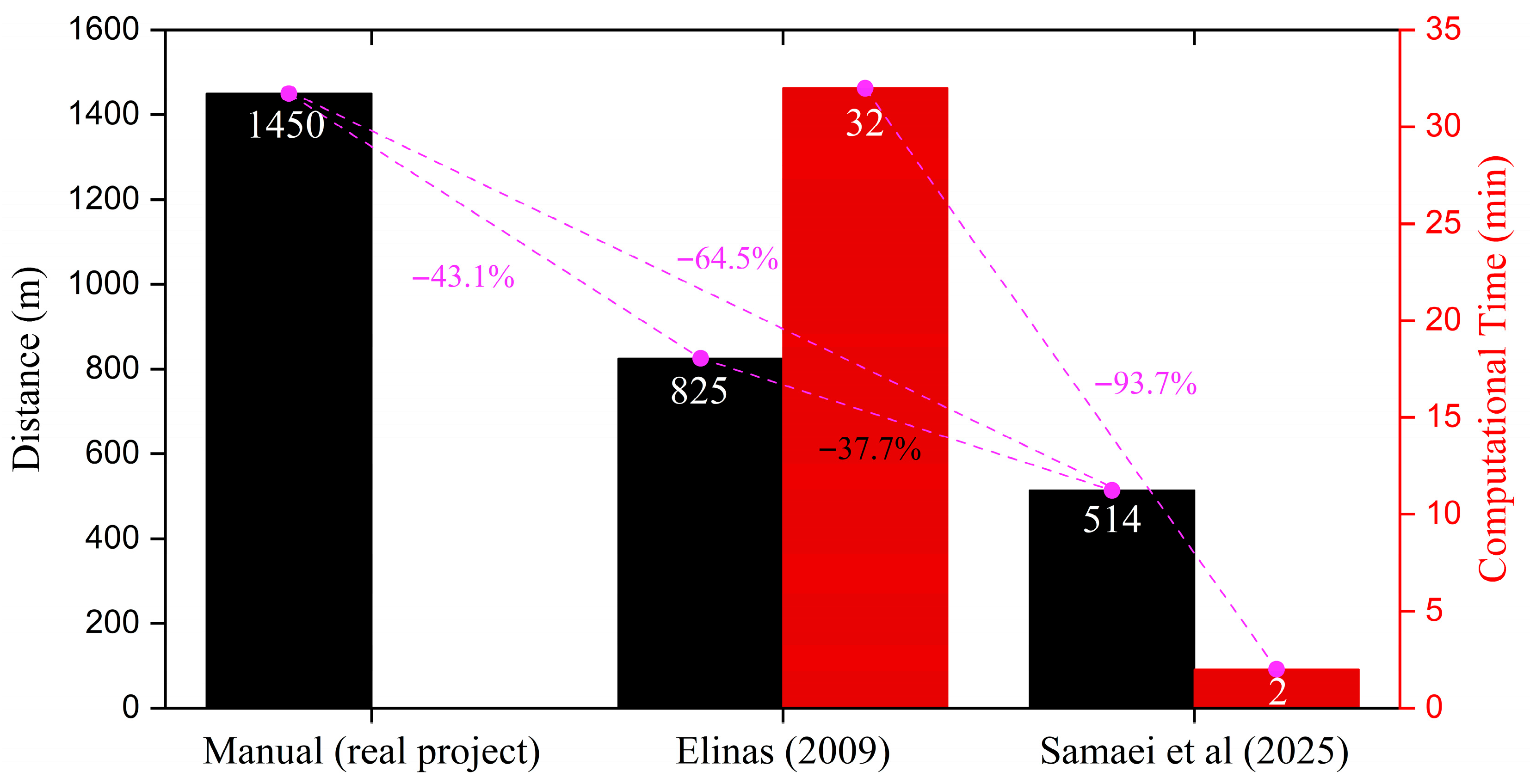
Samaei et al. [15] introduced a deterministic approach for drill rig path planning that builds upon the same fundamental concepts used in the current study. The fundamentals of this method are described in Section 3, the Methodology. However, the method developed in the current study represents a more advanced evolution of that concept. To evaluate the developed methodology, Samaei et al. [15] used data derived from Elinas [9], and the results are illustrated in Figure 4. As seen in this figure, the total travel distance was significantly reduced—from 1450 m in a human-planned path to 825 m using Elinas’s method, and further reduced to 514 m with the newly developed algorithm by Samaei et al. [15].
Figure 4.
Comparison of total rig tramming distance and computational time for different approaches used by Elinas [9] and Samaei et al. [15].
A key innovation in the methodology of Samaei et al. [15] was the incorporation of rig movement constraints as a central factor in route generation, making the solution highly compatible with actual rig manoeuvrability. Additionally, the most notable improvement was in computational efficiency: the path generation time was reduced from 32 min to less than 2 min—an approximately 94% reduction—highlighting the method’s practicality for real-world applications.
Building on the deterministic path-planning framework introduced by Samaei et al. [15], this study substantially extends that approach by introducing a fully integrated multi-rig optimisation strategy based on dynamic programming, a manoeuvre-aware path selection mechanism using the Manoeuvre Efficiency Coefficient (MEC), a quantitative Deviation Penalty Score (DPS) for directional smoothness, and a theoretical justification grounded in coverage path planning principles, thereby delivering a scalable, practically deployable solution for autonomous drill rig tramming in open-pit mining.
Moreover, previous approaches to drill rig path planning have predominantly relied on stochastic optimisation techniques, such as genetic algorithms. These methods introduce randomness, leading to variability in results across different runs; require extensive hyperparameter tuning; and are often computationally intensive, limiting their practicality in dynamic mining environments. In contrast, deterministic approaches guarantee identical outcomes for the same input, eliminate the need for tuning random parameters, and provide fast, predictable computation times. This consistency and efficiency make them far better suited to real-world mining operations, where reliable, rapid replanning is essential amid changing conditions, safety constraints, and the need for reproducible results. The present work, therefore, adopts a fully deterministic framework, leveraging geometric pattern recognition and dynamic programming to deliver fast, consistent, and practically superior tramming paths without the inherent drawbacks of stochastic variability.
2. Data Analysis
In this study, a comprehensive database related to the operation of several Western Australian open-pit mine drill rigs was compiled in collaboration with the industry partner. The database includes hole ID and coordinates, drilling date and time, rig and operator ID, hole depth, and tramming time between holes. The initial step in data analysis was to evaluate operator behavior in managing and sequencing hole drilling in a real project. This analysis provides valuable insights into current industry practices. Moreover, the study primarily validates and demonstrates the developed algorithm’s effectiveness and feasibility using the case study.
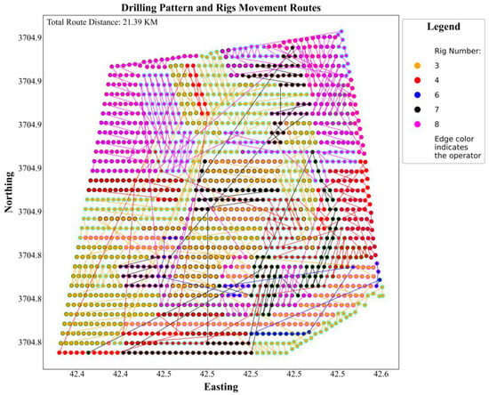
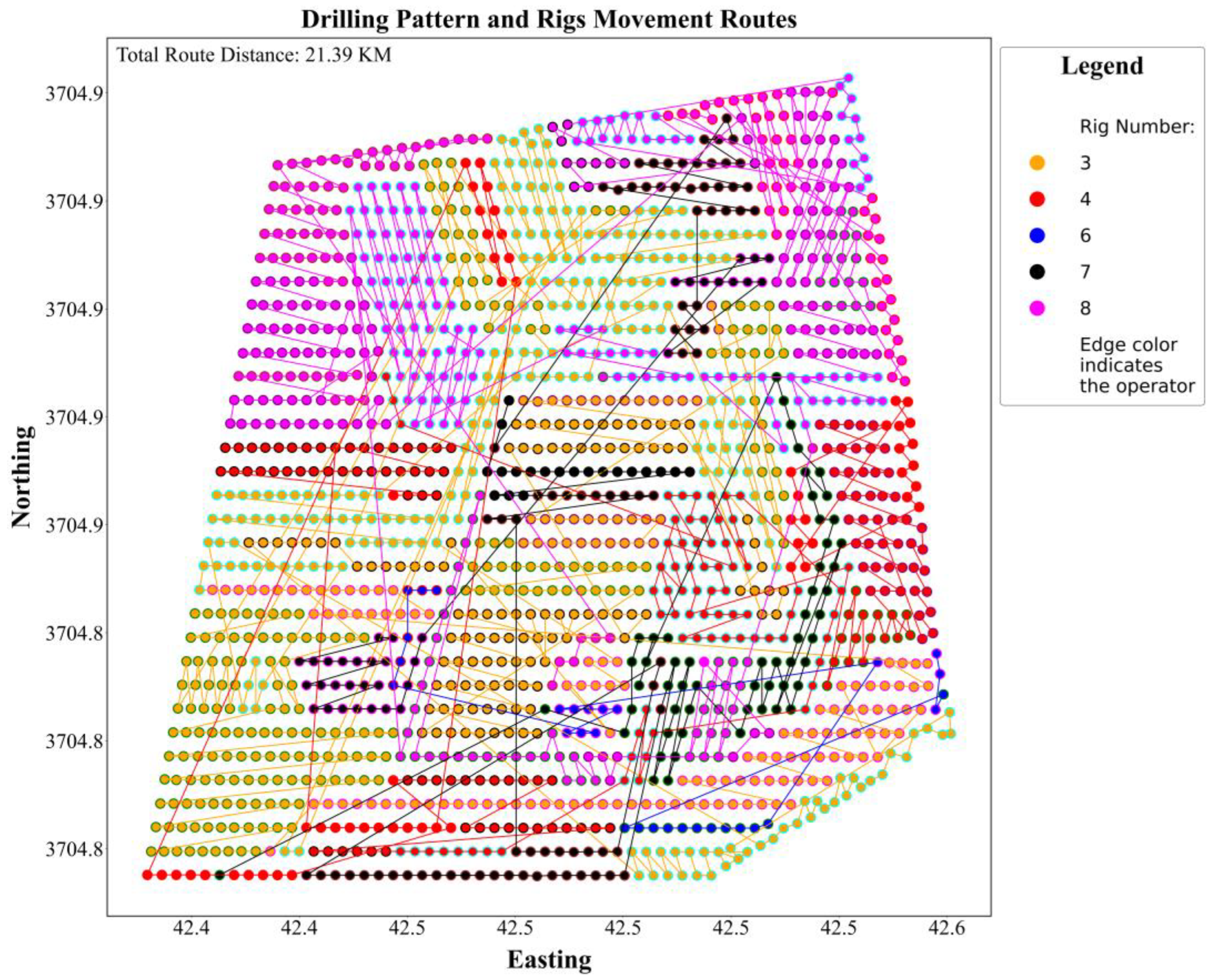
The selected drilling pattern was executed between April and May 2024, comprising a total of 1596 blast holes. The total movement distance for the rigs was 21.39 km, in which non-operational distances, such as the tramming of the rigs from the bench entrance to the first hole, were not considered. The operation involved five drilling rigs and 15 operators, active from 25 April to 7 May 2024. Figure 5 shows a visualisation of the project: each circle represents a drilled hole, with fill colour indicating the rig used and edge colour denoting the operator.
Figure 5.
Drilling pattern and rigs’ movements on the pattern (5 rigs and 15 operators).
This visualisation enables tracking of operator changes and examination of variations in drilling movements among operators. While some spatial consistency is evident (e.g., nearby holes drilled in similar directions by different rigs and operators), structured planning or coordinated management in hole assignment and sequencing appears limited. This is despite the drilling pattern itself being well structured. Figure 5 indicates that despite unplanned and incidental collaboration, the overall execution lacked a systematic strategy to guide rig deployment and hole selection. There are frequent discontinuities, where a single rig breaks from one row and jumps to a far location, which may indicate inefficient rig reassignments. This interleaving can reflect collaboration or on-the-fly adjustments, but also suggests that rig allocation was not strictly zoned, potentially increasing the total movement distance unnecessarily.
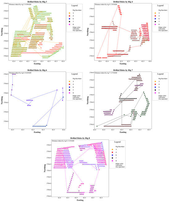
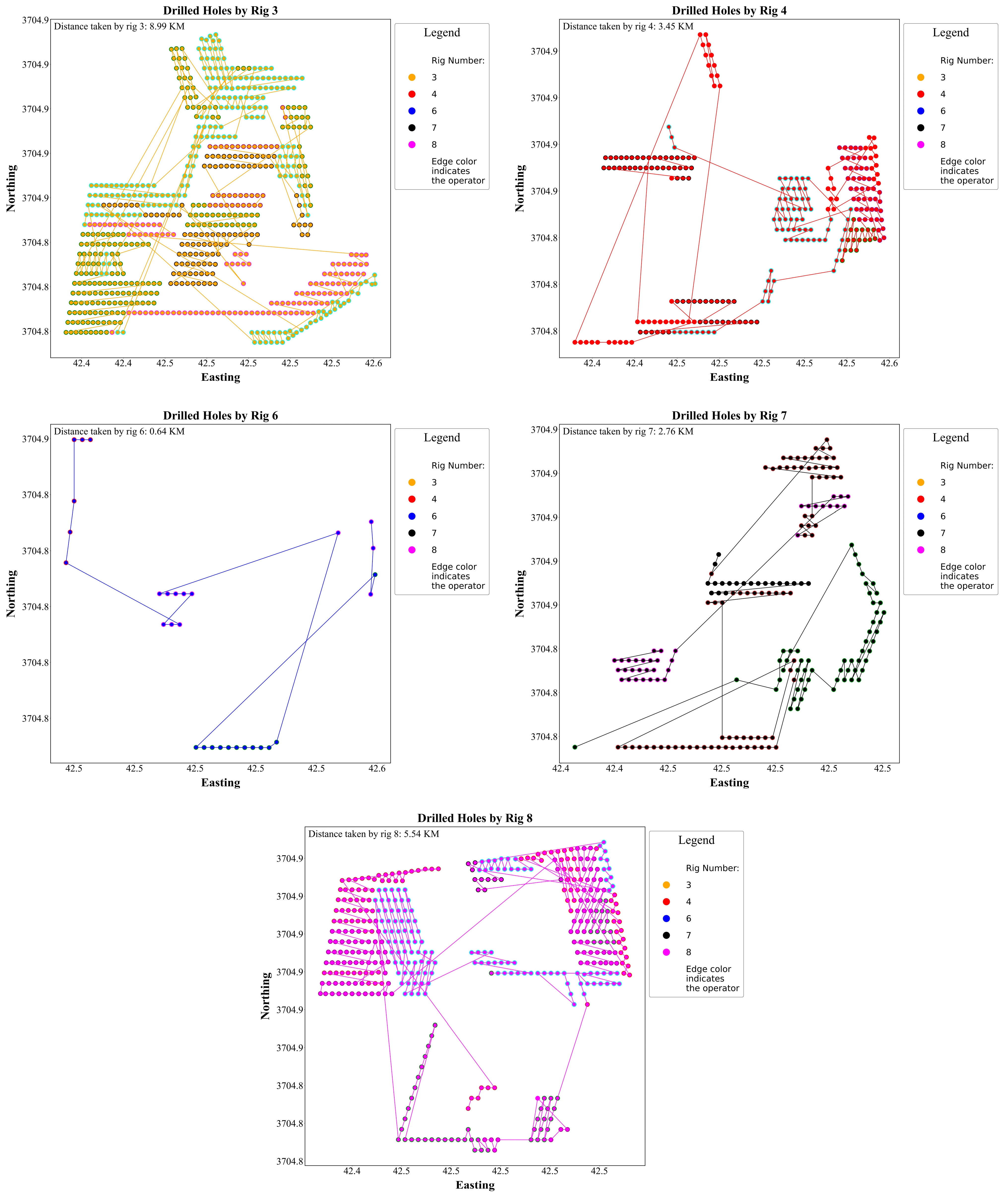
Figure 6 illustrates the drilling activities of each rig across the pattern, while Table 1 presents a detailed breakdown of their operational performance in terms of both distance and time. Rig 3 was the most productive, drilling 691 holes (approximately 43% of the total) and covering 8.99 km. Despite this extensive use, it achieved an efficient 13.02 m per hole and an average tramming speed of 0.67 km/h. Notably, Rig 3 accomplished this over nearly 8 days, with only about 200 extra minutes of tramming time compared to Rig 4, which drilled fewer than half the holes. This suggests effective movement planning, which may result from skilled operation, equipment condition, or well-sequenced routing. Rig 4, despite travelling a shorter distance of 3.45 km and maintaining a comparable distance-to-hole ratio (13.52 m/hole), had a significantly lower tramming speed of 0.34 km/h and took 615.69 min of tramming time. This suggests inefficient movement—potentially due to suboptimal hole assignment, frequent repositioning, or route congestion. Rig 6 had the least deployment, drilling only 30 holes and moving 643.07 metres, resulting in the highest inefficiency ratio (21.44 m/hole). Its modest speed of 0.46 km/h, coupled with scattered movement patterns, indicates it was likely used reactively for fill-ins or unplanned tasks, without a dedicated operational zone. Replacing Rig 6 with Rig 4 under better coordination might have improved overall efficiency. Rig 7 drilled 194 holes over 2.76 km, yielding a 14.22 m/hole ratio and a moderate speed. Its slightly fragmented path hints at less structured task allocation. Conversely, Rig 8 demonstrated balanced efficiency, drilling 426 holes while travelling 5.54 km, also achieving a 13.02 m/hole ratio and likely benefiting from an effective deployment strategy. From the last row of Table 1, 41.32 h (2479.73 min) were spent on tramming among holes, which was 8.34% of the total operation time.
Figure 6.
Total drilled holes by each rig and movement of rigs during the project.
Table 1.
Statistics of the drilling project performance.
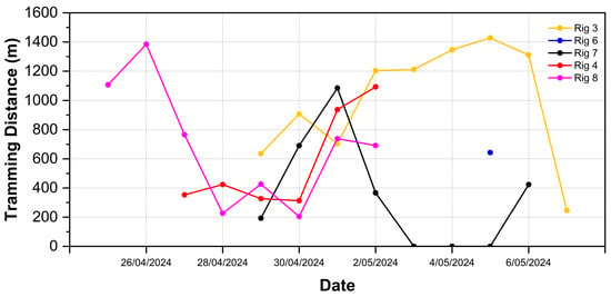
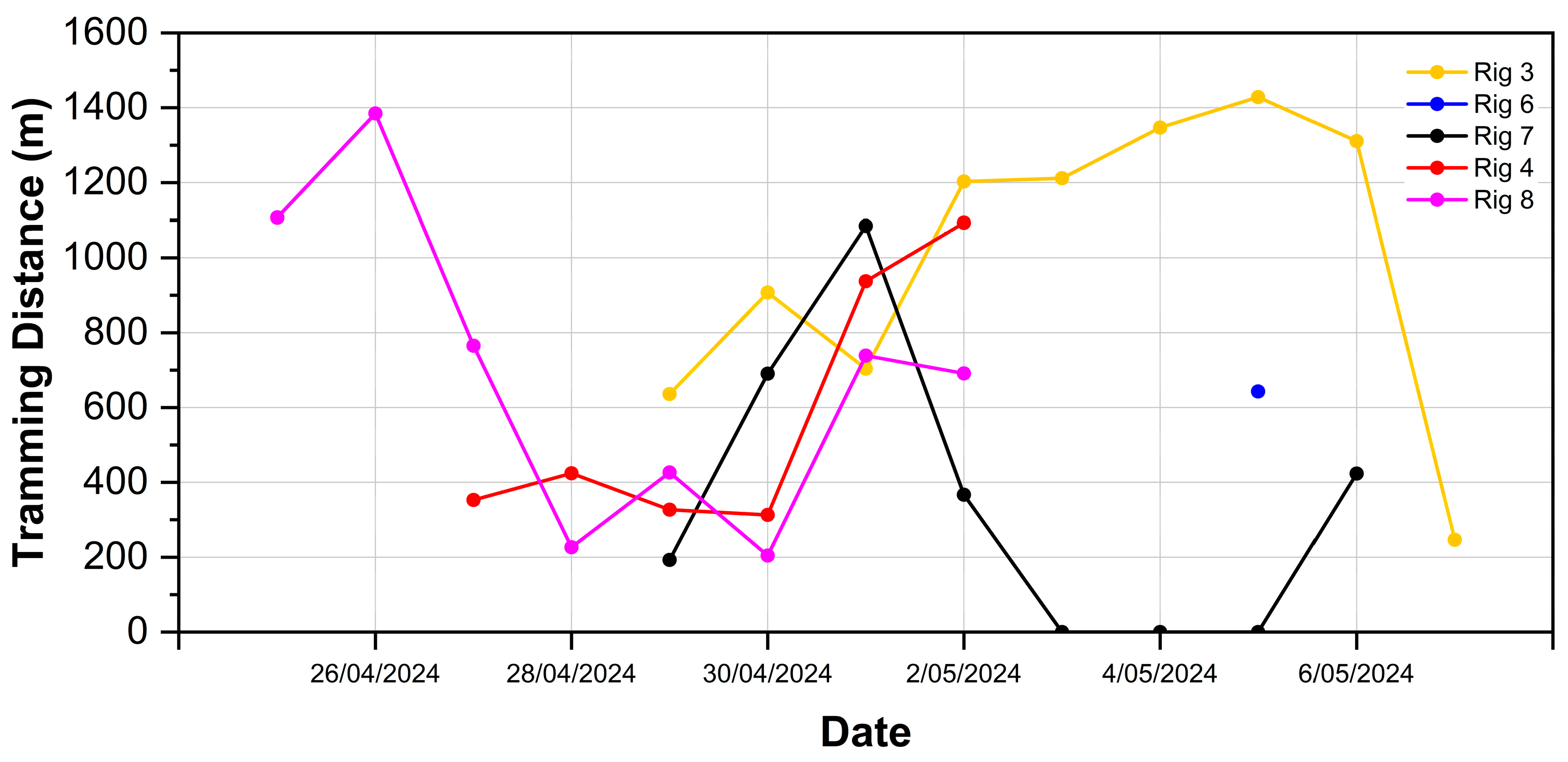
The daily usage data offers insights into how rig deployment evolved throughout the project timeline, as shown in Figure 7 and Table 2.
Figure 7.
Daily activities of rigs.
Table 2.
The result of route division among rigs.
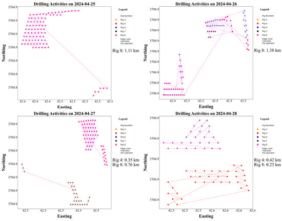
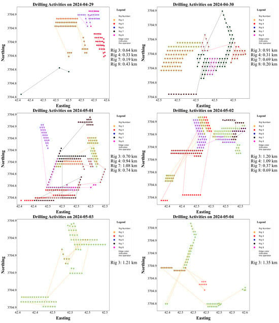
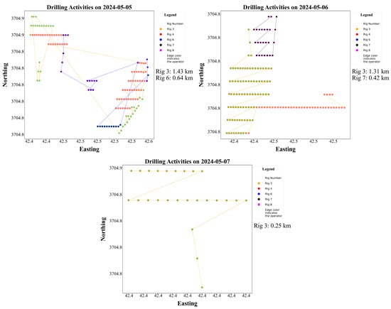
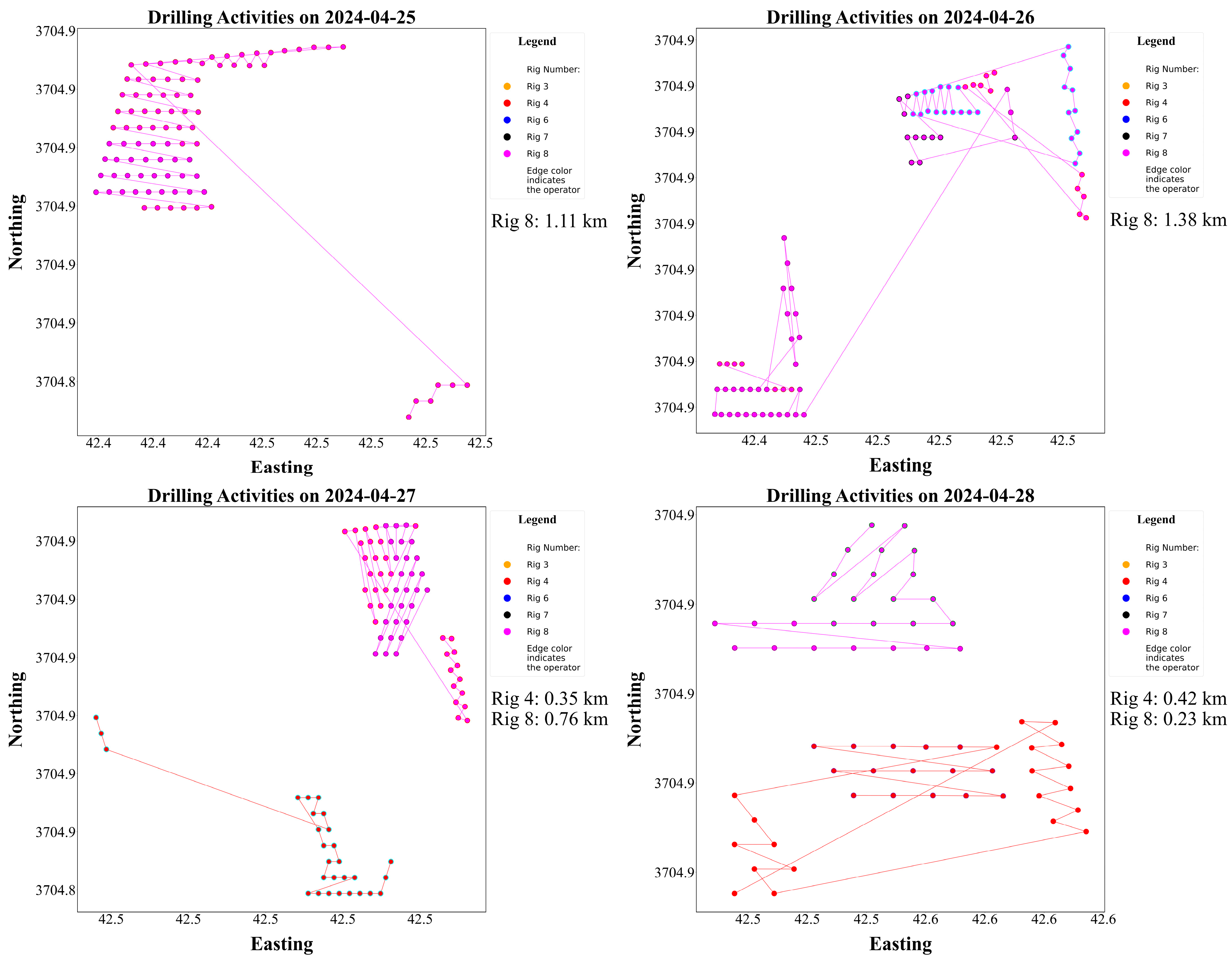
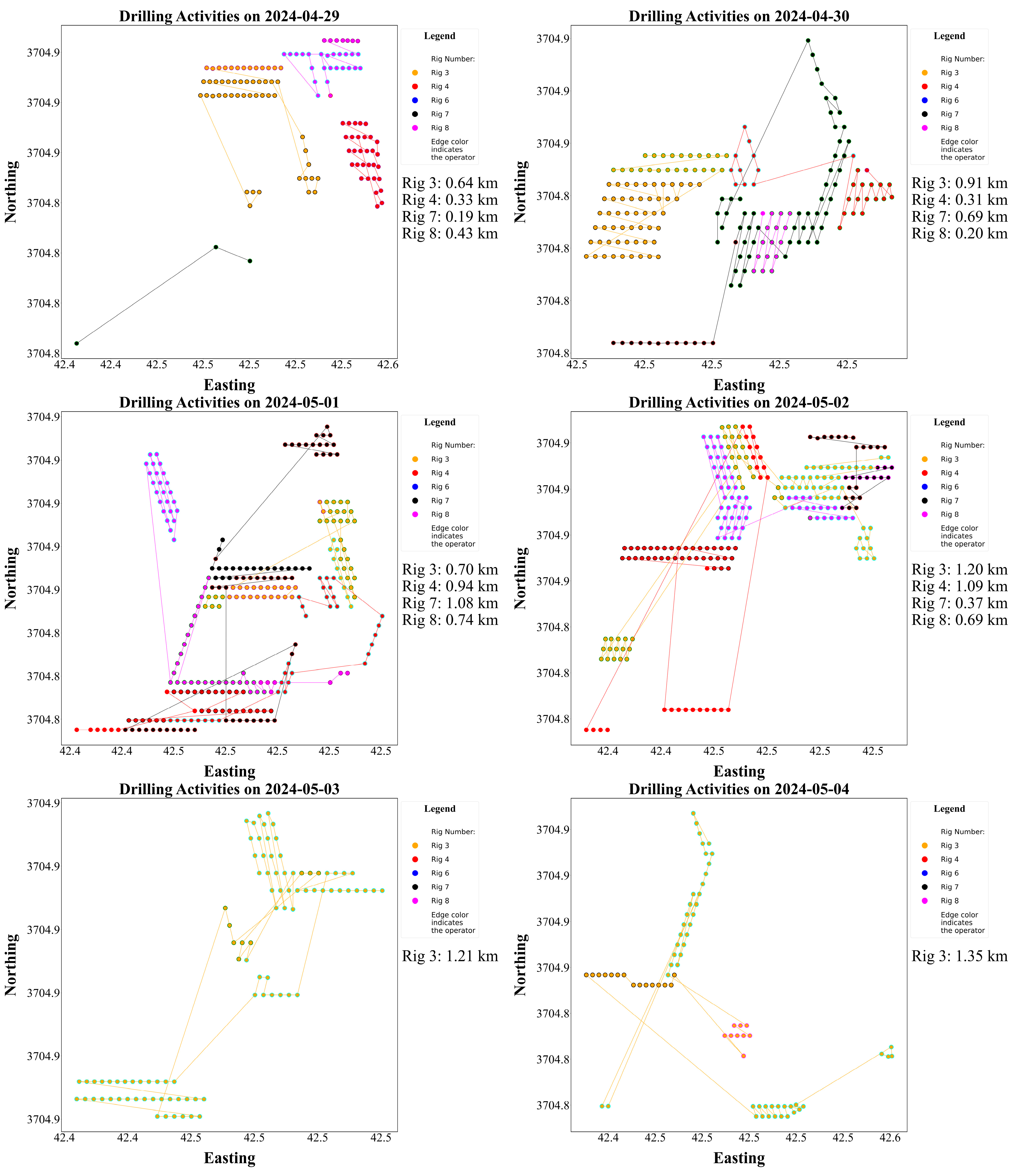
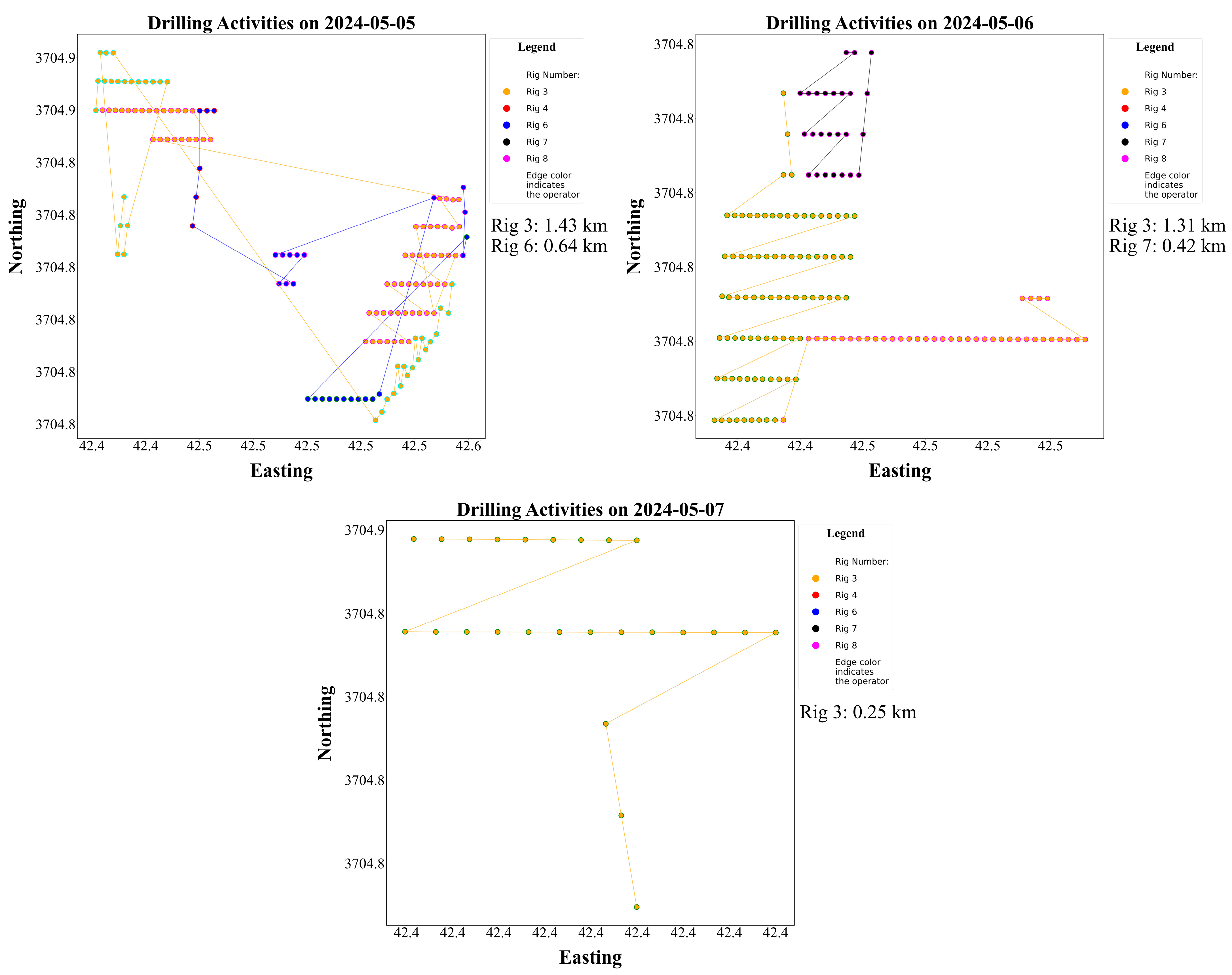
As seen in Figure 8, during the initial phase (25–26 April), only Rig 8 was operational, probably setting the foundation or establishing the first rows of the pattern. Activity scaled up from 27 April onward with the introduction of Rig 4, followed shortly by Rig 3 and Rig 7 on 29 April. This marked a clear transition into the main operational phase, during which the workload was distributed across multiple rigs. From 29 April to 2 May, the project experienced peak collaboration, with up to four rigs operating simultaneously. This period contributed to the most significant daily distances, particularly on 1 and 2 May, indicating high production rates. The data suggests that the deployment was deliberately intensified during these days to meet schedule targets or capitalise on favourable conditions. After 2 May, a gradual drawdown is observed. Rig 4 ceased activity, and the remaining rigs continued to operate with decreasing overlap. Rig 6 appeared briefly on 5 May, suggesting a reactive response to remaining or delayed areas, and only Rig 3 persisted until the final day, indicating a wrap-up phase focused on residual or hard-to-reach holes. The temporal distribution reflects a front-loaded strategy for Rig 8, mid-campaign concentration for Rig 4 and Rig 7, and sustained back-end performance by Rig 3. This sequencing indicates purposeful scheduling and may reflect availability, rig capability, or zone-based task assignment.
Figure 8.
Daily drilling tasks for rigs during the project.
This study examines the non-drilling component of drill rig operations, focusing on tramming time. While drilling duration can be influenced by various factors—including rig availability, bit size and wear, and ground conditions—these aspects represent a broad field of research beyond the scope of this work. Instead, this investigation began with a practical question: How significant is tramming in the overall operation time, and to what extent can optimising tramming paths cut down time in a real-world drilling project? To answer these questions, it is essential to investigate tramming time and understand its contribution to the overall operation. According to Table 1, the total tramming time adds up to approximately 41 h, which translates to around 1.7 days out of the 12-day project duration, accounting for nearly 14.23% of this case study. The percentage was calculated relative to the calendar project duration (12 days × 24 h = 288 h), representing the overall project timeline.
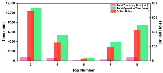
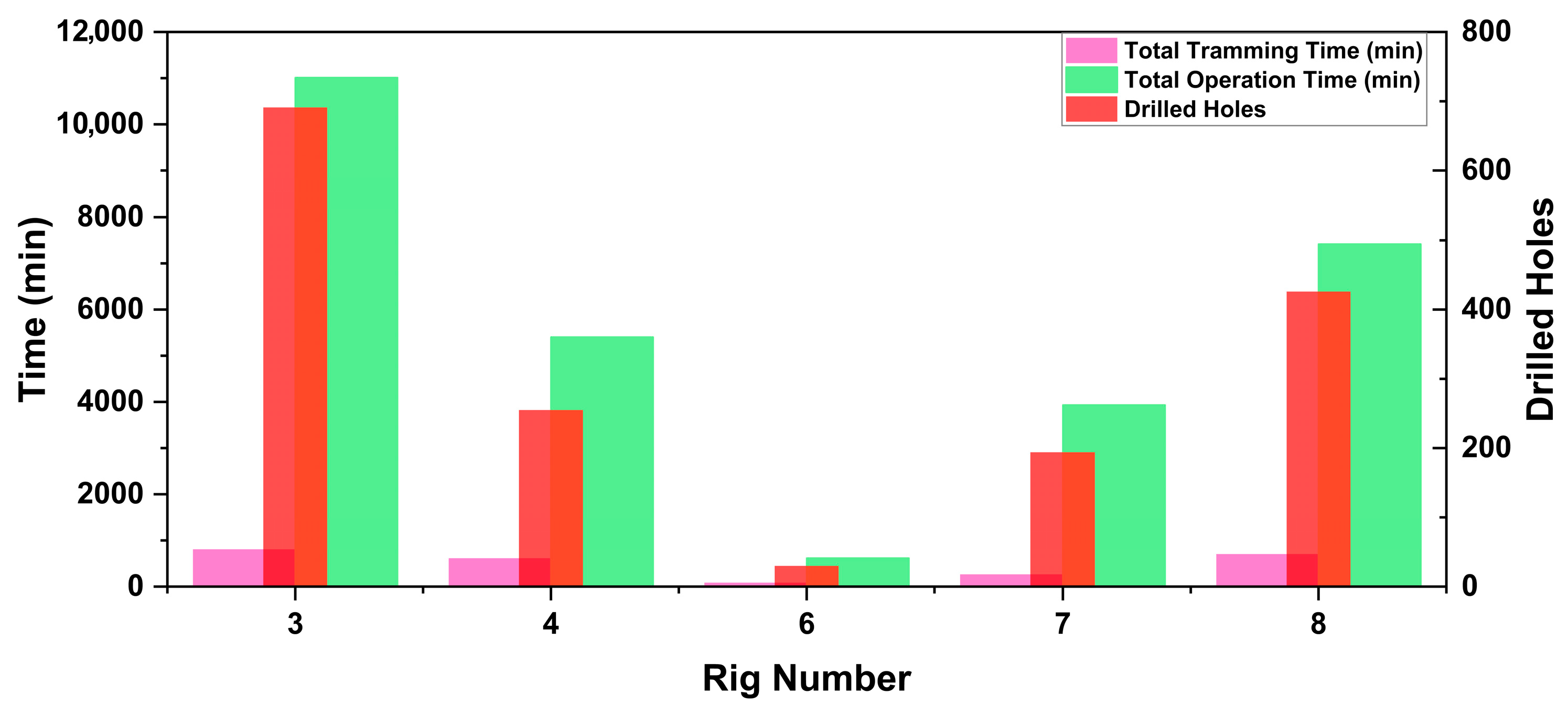
Figure 9 compares operational time, tramming time, and the number of drilled holes for each rig. Although Rigs 3, 4, and 8 recorded similar tramming durations, Rig 3 completed significantly more holes and had a longer total operational time than the other two. This discrepancy can be further examined through the hole-to-hole tramming time and average tramming speeds listed in Table 1. Several factors may have contributed to these differences, including rig availability, operator performance, and the condition of the bench surface. The influence of these variables warrants further investigation in future studies. Another potential factor affecting tramming time and speed is the rig model; however, Rigs 4 and 8 used the same model, suggesting that other operational or planning aspects played a more significant role in their performance variations.
Figure 9.
Tramming time, operation time and number of drilled holes by different rigs.
It is important to note that the tramming time shown excludes other non-drilling intervals such as collaring, retraction, levelling, and resetting.
3. Methodology
A key challenge in drill rig tramming automation is in sequencing hole drilling. Essentially, this task is similar to a variation of the TSP, where the aim is to find the most efficient route between multiple points. Factors such as machine manoeuvrability could be incorporated to simplify the problem. However, the TSP—and by extension, the hole sequencing problem—remains NP-hard in computational complexity theory [10]. In this study, a key challenge involved the identification and classification of drilling patterns. For a human operator, recognising the type of pattern—whether staggered, rectangular, or square—is intuitive upon visual observation. However, when only the coordinate data of drilled holes is available, it becomes difficult to perceive the overall structure or scale of the pattern. This difficulty parallels the challenge faced by automated systems, which must extract spatial logic and optimise paths without visual intuition, relying solely on geometric data.
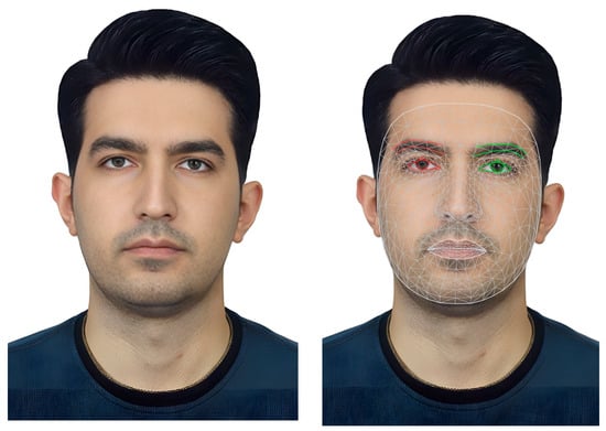
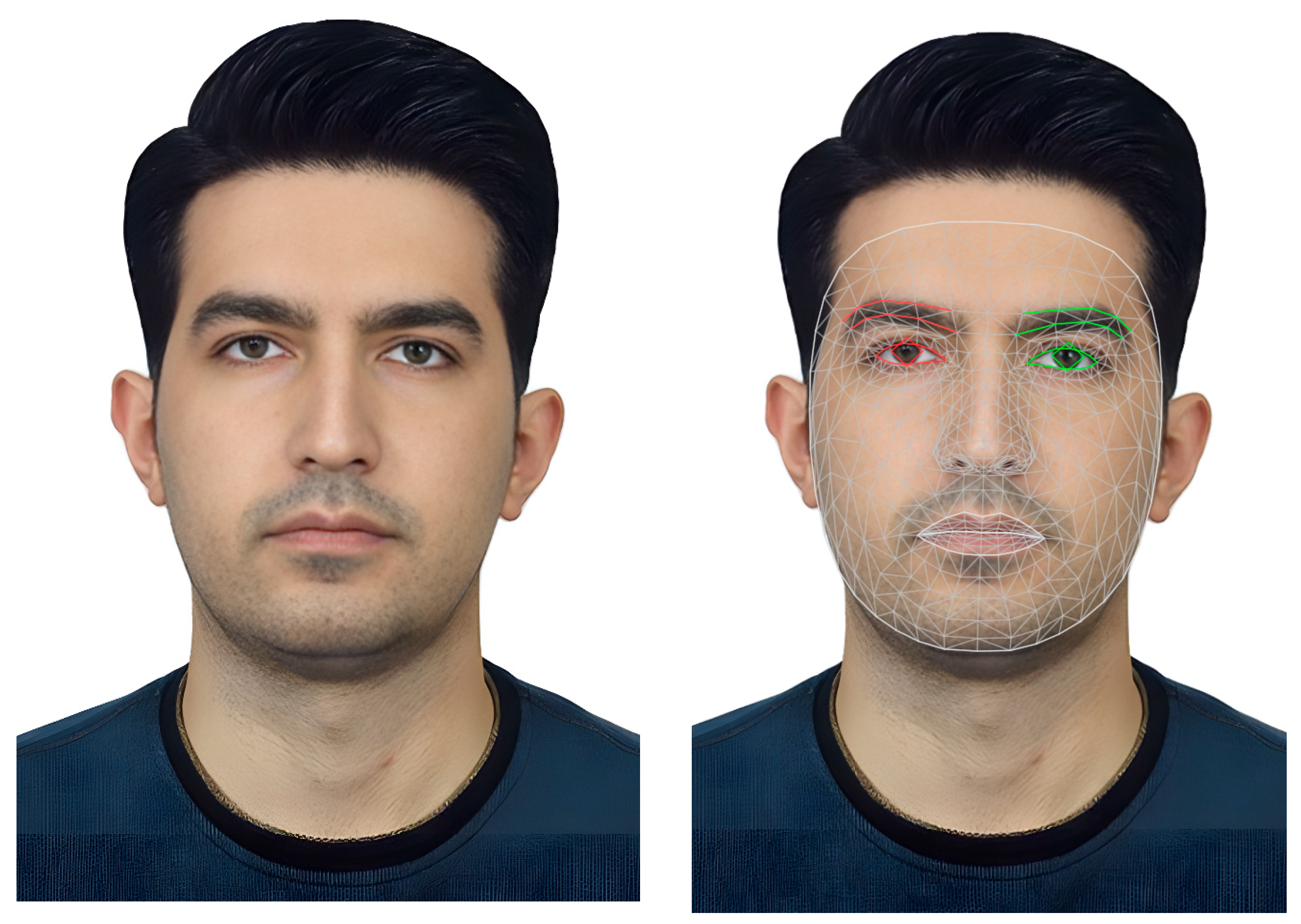
In this study, Delaunay Triangulation (DT) serves as the foundation for developing a comprehensive deterministic path-planning approach. It enables the identification of hidden paths that rigs can follow to complete a drilling pattern. DT is a well-established method in computational geometry and has been widely applied in fields such as face recognition [16] (Figure 10), Geographic Information Systems (GIS) [17], and Finite Element Analysis (FEA) [18].
Figure 10.
Face recognition using DT.
The computational framework was implemented in Python; however, full algorithmic reproducibility is limited, as flowcharts, detailed pseudocode, and internal parameter specifications cannot be disclosed due to industrial confidentiality constraints.
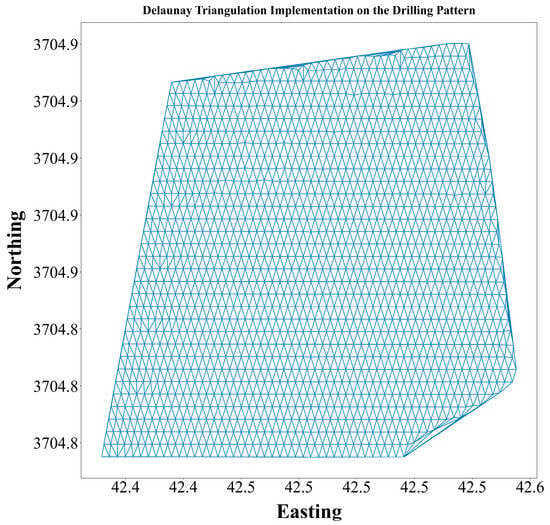
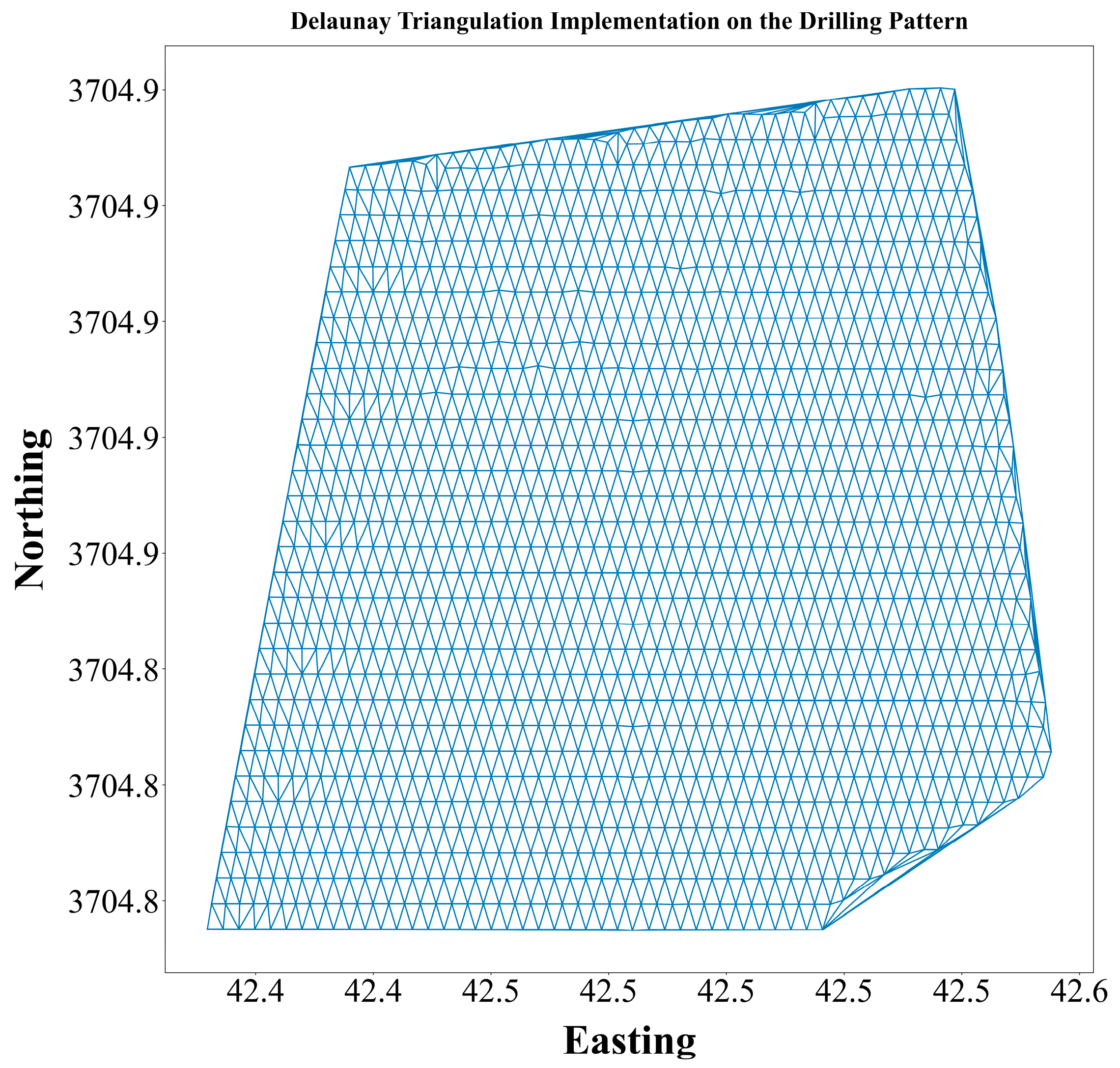
Figure 11 displays the outcome of the DT implementation on a sample drilling pattern.
Figure 11.
DT implementation on the drilling pattern.
As previously mentioned, the tramming path optimisation problem can be modelled as a variant of the TSP. For instance, with 1596 drilling locations, the total number of possible routes is 1596 factorial, a number so large that computing the optimal route through exhaustive search would require an impractical amount of time. A common approach to solve such combinatorial problems is to use evolutionary algorithms—such as Genetic Algorithms (GA), Ant Colony Optimisation (ACO), or the Imperialist Competitive Algorithm (ICA), to find near-optimal solutions [9]. However, these methods face two significant limitations in the context of mining operations: (1) their degree of optimality often varies between runs due to stochastic processes and hyperparameter sensitivity [11] and (2) their high computational cost makes them unsuitable for dynamic mining environments where frequent re-scheduling and real-time decision-making are required [19]. In such conditions, solutions must be generated rapidly with consistent reliability, which these algorithms may not guarantee. On the other hand, it may be considered impractical to obtain a deterministic and exact solution for this problem, as it is practically impossible due to the immense computational complexity involved. However, by applying a simplifying assumption without violating optimality, a substantial number of potential solutions can be excluded. The assumption is based on the practical observation that drill rigs tend to move in straighter paths, and movement in a straight line always gives shorter distances in comparison to a route with several turnings. This study leveraged this behavioural tendency and incorporated it alongside the results derived from DT to streamline the path-planning process. Therefore, the algorithm was designed to find straight paths within the DT-generated paths.
4. Implementation and Results of the Proposed Approach
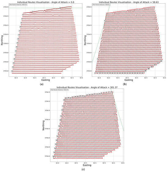
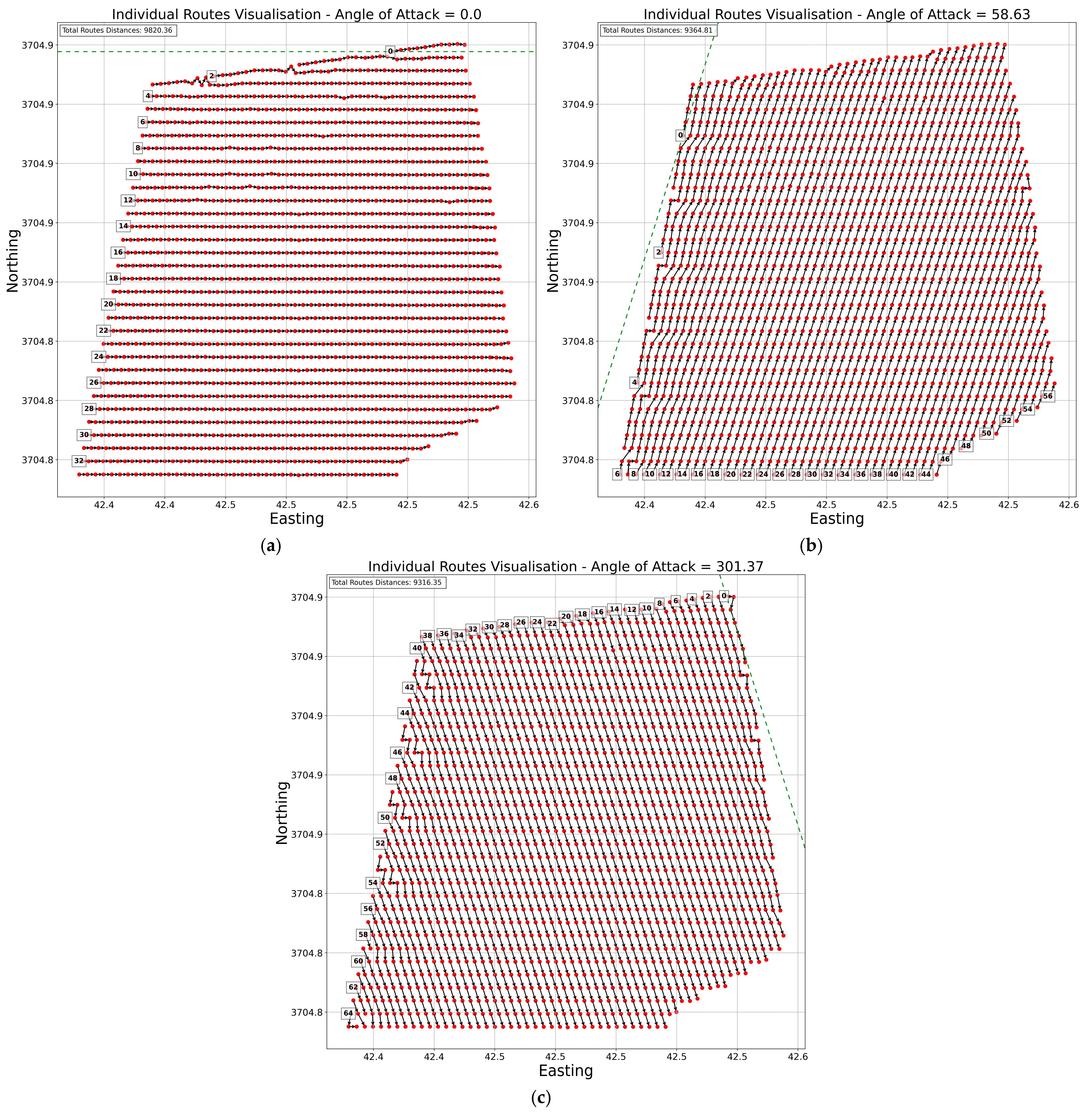
The path planning process has two stages. First, individual routes are identified. Second, the manoeuvre type required for the rig is determined. A route is defined as a straight sequence of consecutive holes that are aligned with a selected Angle of Attack (AoA) within a specified lateral tolerance. The short tramming movements between adjacent holes within a route are called segments. To identify routes, a pre-processing module first determines the AoA, which represents the direction from which the rig approaches the holes. An AoA of 0° corresponds to a West-to-East direction. The number of angles of attack varies between patterns, depending on the orientation of the drill holes. In the current dataset, the detected angles of attack were 0°, 58.63°, and 301.37°. In the next phase, the algorithm groups holes that align closely with these angles and are within a specified lateral distance from one another, effectively forming individual routes.
As shown in Figure 12, both the total distance and the number of individual routes varied across the generated path patterns. These metrics served as key criteria for selecting the optimum movement pattern. However, they were not the sole factors influencing this decision; additional parameters will be introduced and discussed in subsequent sections to support a more comprehensive evaluation.
Figure 12.
Detected individual routes for drilling with different AoAs: (a) 0°, (b) 58.63°, and (c) 301.37°. The green dashed line shows the reference line with a slope equal to the AoA.
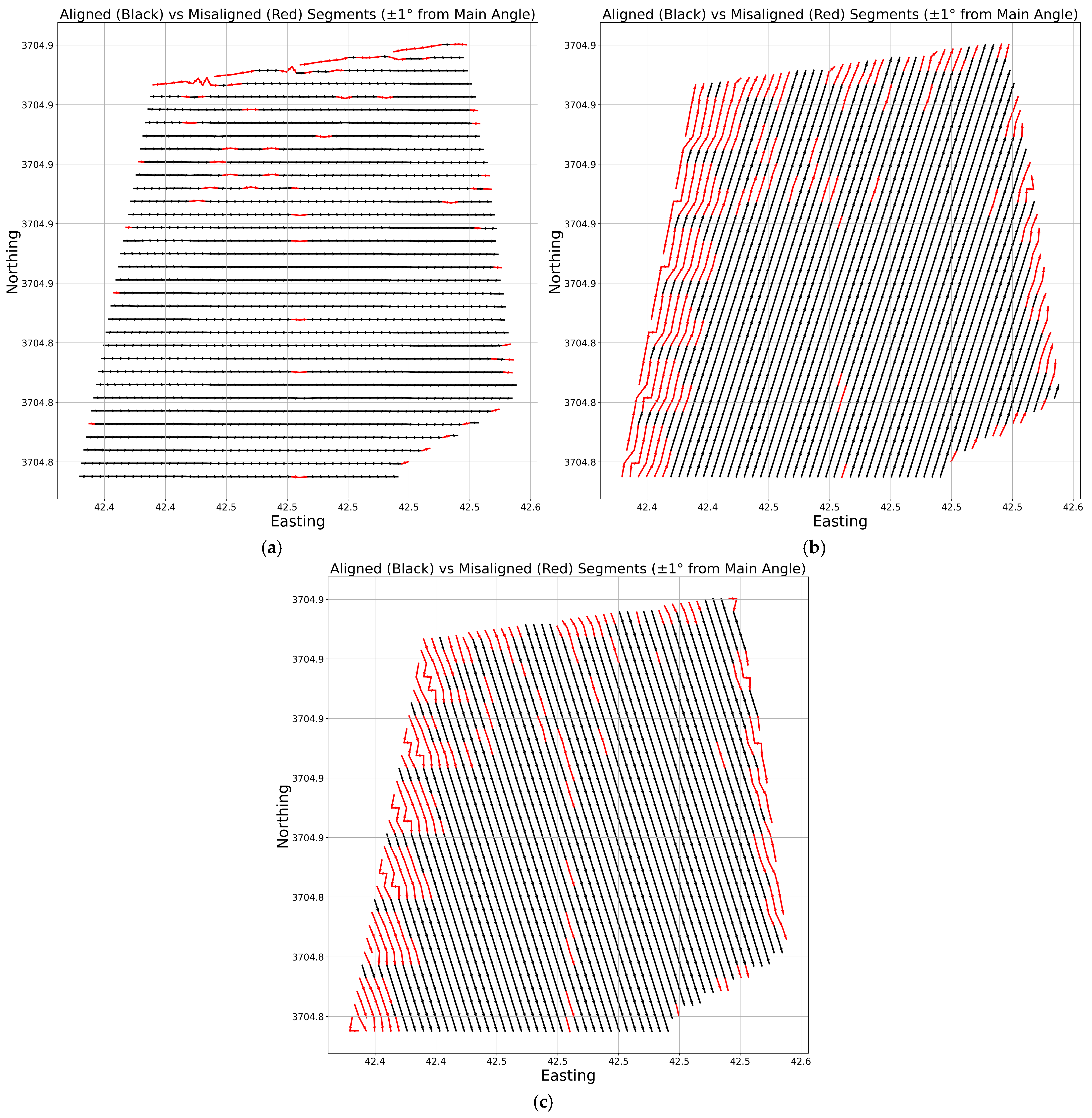
As shown in Figure 13, some irregularities appear in the middle and around the edges of the pattern, where the generated path deviates from the intended AoA. Part of these irregularities stems from the design and placement of holes near the pattern boundaries. Additionally, the data used represents the actual drilled hole locations, not the original design layout. Using the design hole data would likely reduce these discrepancies. Nevertheless, the algorithm demonstrated strong performance in identifying and managing such anomalies within the pattern.
Figure 13.
Detected misaligned segments (red lines) from AoAs for each path pattern: (a) 0°, (b) 58.63°, and (c) 301.37°.
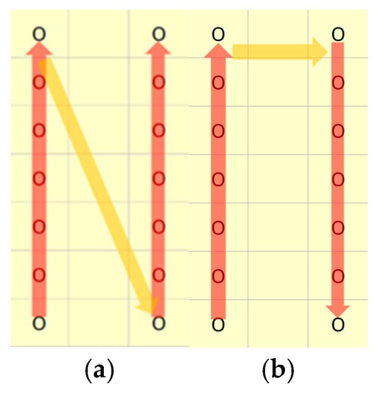
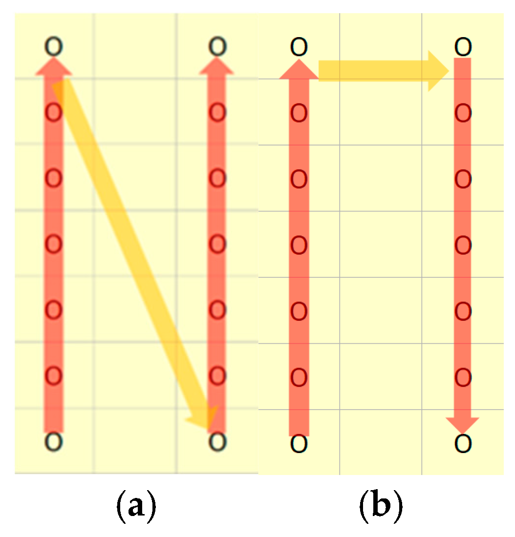
Based on the literature review, data analysis, and discussion with the experts in this field, two main manoeuvre types were identified: zig-zag (Figure 14a) and Continuous (switch-row) turning (Figure 14b). As illustrated in Figure 2a and Figure 4, rig operators tend to favour straight-line movement, as it is easier to perform and reduce rig wear. When transitioning between routes, a common approach is to reverse entirely along the previous path, zig-zagging, before starting the next route—an action that significantly increases the total travel distance, as the reverse segment is nearly as long as the route itself. Alternatively, the Continuous (or switch-row) manoeuvre allows the rig to begin the next route from the nearest end of the adjacent route, reducing unnecessary travel.
Figure 14.
Two common types of drill rig manoeuvring: (a) zig-zag and (b) continuous (switch-row).
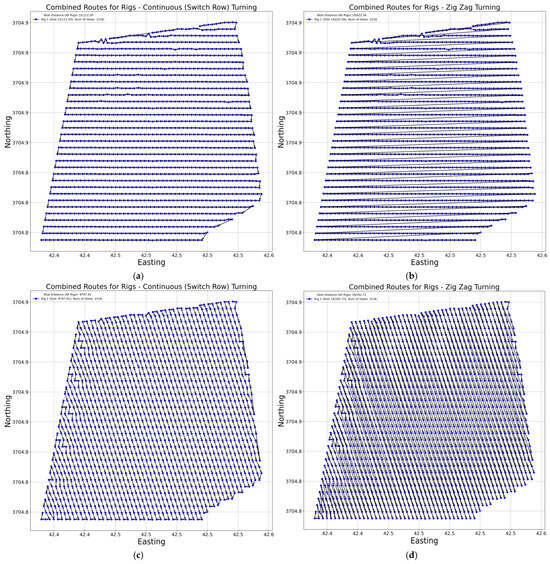
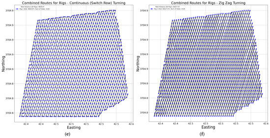
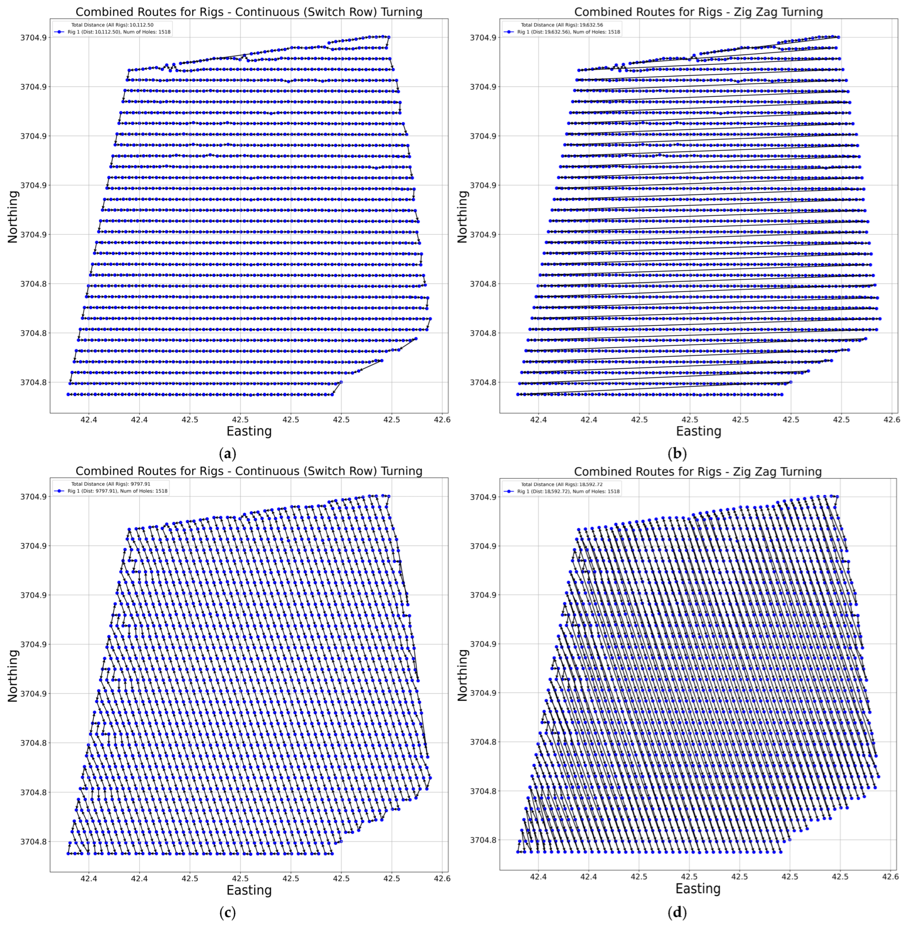
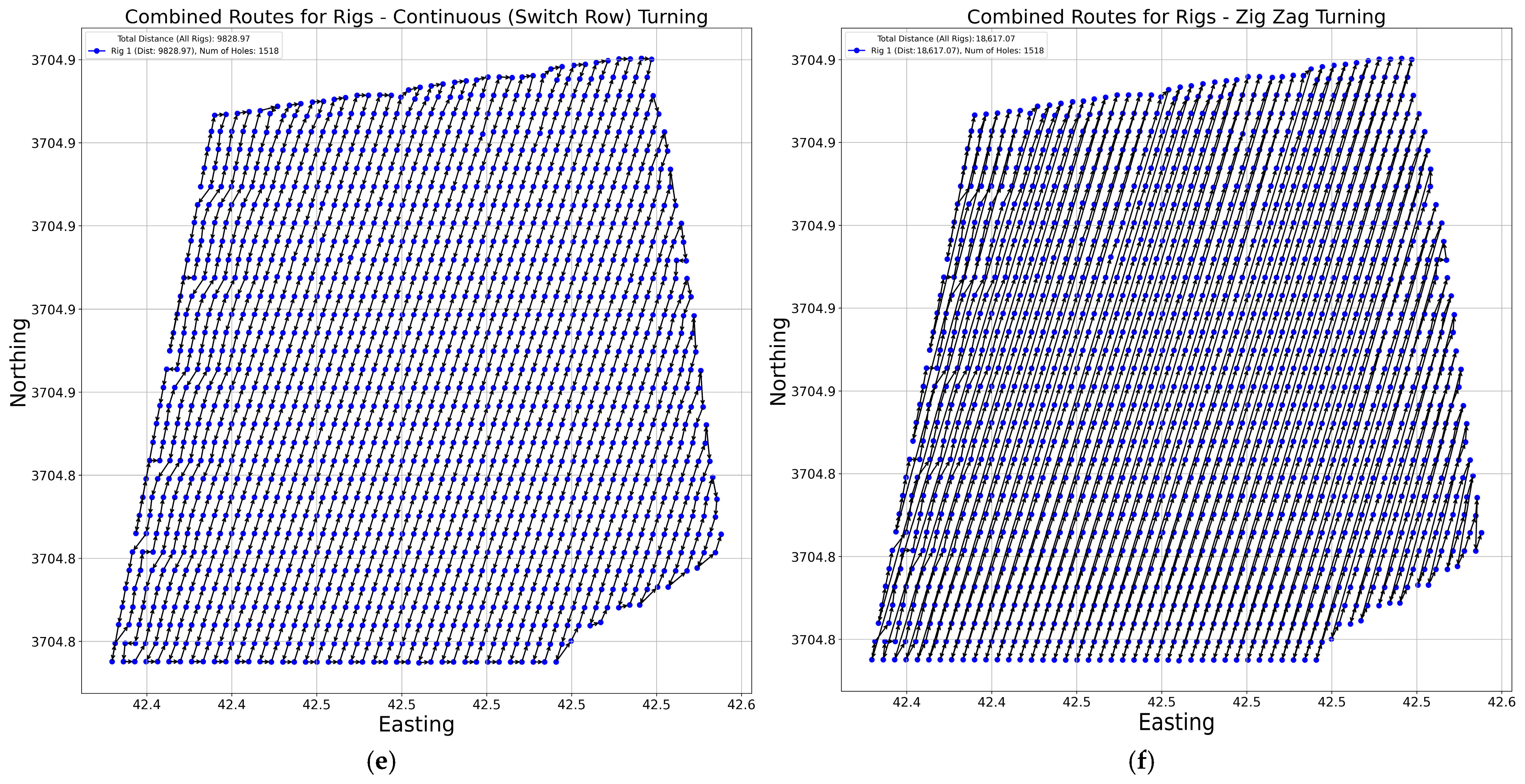
Figure 15 presents the outcomes of applying two turning strategies—continuous (switch-row) and zig-zag—across three alignment categories: 0°, 58.63°, and 301.37°. In the 0° alignment, the continuous turning resulted in a total distance of 10,112.50 m, whereas the zig-zag manoeuvre increased this to 19,632.56 m, reflecting a 94% increase. For the 301.37° alignment, the total distance for continuous turning was 9797.91 m, compared to 18,592.72 m for zig-zag, marking a 90% increase. Similarly, in the 58.63° alignment, continuous turning covered 9828.97 m, while the zig-zag approach reached 18,617.07 m, which was a 89% increase. These results confirm that, across all orientations, the zig-zag turning strategy consistently leads to nearly double the total rig travel distance compared to continuous turning.
Figure 15.
The results of path generation for single rig operation: (a) 0° switch-row, (b) 0° zig-zag, (c) 301.37° switch-row, (d) 301.37° zig-zag, (e) 58.63° switch-row, and (f) 58.63° zig-zag.
4.1. Multi-Rig Drilling Operation
In the previous sections, all model developments were based on a single-rig operation. However, as presented in Section 2, the actual project involved five drilling rigs. In practice, most projects deploy multiple rigs simultaneously, making it essential for the algorithm to accommodate multi-rig scenarios. For the current study, it was assumed that all rigs were of the same type and operated under identical conditions. Excluding the type of drill rig, three main criteria were defined within the study, and a question was raised about how the pattern should be divided among multiple rigs to satisfy the following conditions.
- The distances and number of holes between rigs should be approximately equal, resulting in the same value for the fraction of distance over the number of holes.
- A rig cannot start operation from the middle of an individual route.
- Routes must be distributed sequentially among rigs.
The first criterion was introduced to ensure that each rig was assigned a similar total drilling distance and an approximately equal number of drill holes, promoting workload balance. The second criterion prevented dividing individual routes between rigs, as interrupting a straight route and assigning its remainder to another rig is inefficient and unnecessary when a single rig can complete the route. The final criterion aimed to avoid sporadic or scattered route allocations, which would result in excessive tramming distances as rigs move between non-adjacent routes.
Due to the large number of drill holes relative to the limited number of rigs, the number of possible combinations in this problem—and in similar mining applications—can reach into the thousands of scenarios. Equation (1) quantified the total number of potential solutions for the current study.
where k is the number of individual routes and n is the number of rigs.
However, only one of these combinations represented the optimal solution, and the algorithm needed to be capable of identifying it efficiently and accurately. To achieve this, Dynamic Programming (DP) was employed in this study as the solution method.
Richard Bellman formalised DP in the early 1950s as a framework for solving complex problems by breaking them down into simpler subproblems with overlapping structure and optimal substructure properties [20]. The term “dynamic” was chosen to highlight the time-sequential nature of the problems being addressed, while “programming” referred to the then-standard terminology for planning or decision-making processes, particularly in military and operations research contexts [21]. DP is particularly effective for problems where a solution can be composed of solutions to overlapping subproblems. It avoids redundant computation by storing and reusing subproblem results—either via a top-down recursive approach with memorisation or a bottom-up iterative method known as tabulation [22]. This reuse often leads to significant reductions in computational complexity, transforming problems that would otherwise require exponential time into polynomial-time solutions. Depending on the structure of the problem, DP algorithms typically make use of organised data structures such as matrices or trees to store intermediate results. For example, in grid-based problems or sequence alignment tasks, two-dimensional arrays are commonly used, with each cell representing a subproblem whose value is computed using previously computed entries [22].
A fundamental aspect of designing a DP solution is the formulation of a recurrence relation (also known as a transition function). Establishing the correct recurrence is essential for the correctness and efficiency of the DP algorithm [22]. For the current study, the recurrence relation was developed as follows:
where r is the number of rigs, j is the endpoint of the current segment (consecutive routes) being considered, and i is the splitting position. represents the minimum possible maximum sum when dividing the first j routes into rigs.
The dynamic programming minimises the maximum total tramming distance allocated to any rig (minimax objective), thereby achieving approximate equality of total travel effort across rigs and promoting workload balance in terms of distance. Although the formulation does not explicitly constrain the number of holes per rig or the distance/hole ratio, pre-grouping of holes into routes with similar geometric properties (burden and spacing) yields reasonably consistent hole densities; consequently, the achieved distance balance served as a close proxy for balanced distance/hole ratios in the studied patterns (Criterion I). Future extensions may incorporate the ratio directly into the objective for stricter enforcement. Criterion II was considered in the formula by prohibiting the splitting of individual routes, which was strictly enforced by treating each route as an indivisible unit: indices and referred only to complete routes, and prefix sums were computed over whole routes, ensuring that no rig began operation in the middle of a route. Criterion III was considered based on the recurrence structure. The DP considered only prefix assignments of the ordered route sequence: the first rigs received the first routes and the -th rig received the immediately subsequent consecutive block (routes to ). Non-consecutive or interleaved allocation was structurally impossible.
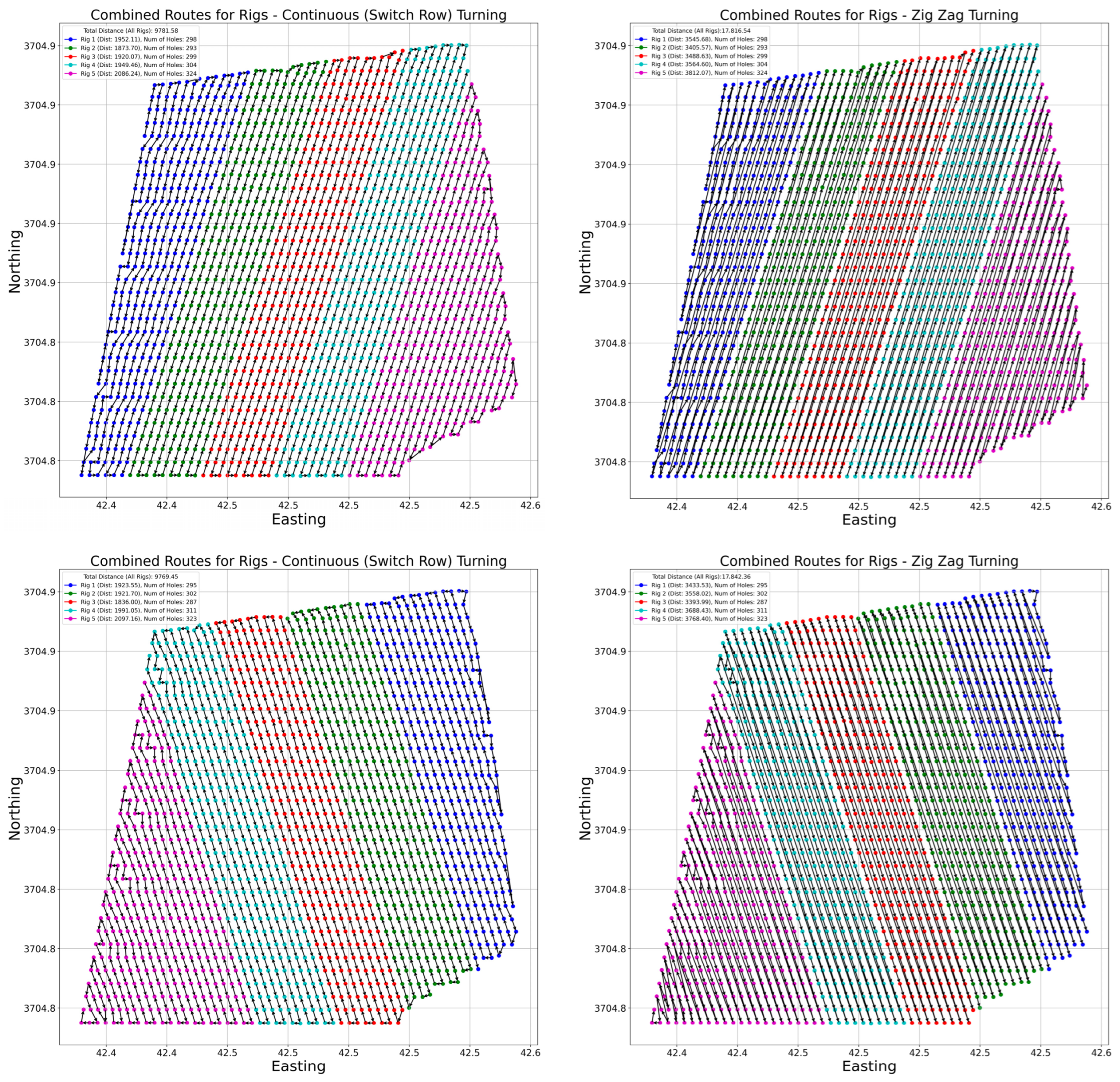
After introducing the DP into the path planning algorithm, the code was able to divide routes among rigs (see Figure 16). Table 2 presents the results of route division among the rigs. The holes were distributed relatively evenly across the rigs, with travel distances remaining comparable. For the switch-row turning manoeuvre, the distance per hole closely aligned with the Burden and Spacing configurations, yielding values of 6.7 m/hole and 6.4 m/hole, respectively. However, when alternative manoeuvre types were employed, the distance per hole increased significantly, by approximately 70% to 80%, indicating a substantial loss in routing efficiency. The comparison between the distance-per-hole obtained from the developed model and that from manual management reveals a substantial improvement in routing efficiency.
Figure 16.
Path generation results for multi-rig drilling.
4.2. Determination of Rig Manoeuvre Efficiency Coefficient
As demonstrated in Figure 15 and Figure 16, the type of rig manoeuvre employed between individual routes could significantly affect the total drilling distance, with differences reaching up to 50% in some cases. From a distance-efficiency perspective, Continuous or switch-row turning proved to be the most effective approach—particularly when individual drilling routes were long—since reversing over extended distances is often impractical and uneconomical. Despite this, field observations have shown that operators frequently opt to reverse, likely due to its operational simplicity without any plan in their rig movement.
However, in scenarios where space is limited or the individual routes are relatively short, reversing can be more practical than executing a full turning manoeuvre. This suggests that an effective path planning strategy should incorporate a hybrid approach, combining both zig-zag and Continuous manoeuvres based on situational demands. To address this, the current study introduced Equation (3), which defines the conditions under which each manoeuvre should be applied. The Manoeuvre Efficiency Coefficient (MEC) (Equation (3)) was introduced as a decision metric, calculated as the ratio of the turning distance in the Continuous manoeuvre to that of the zig-zag manoeuvre.
Through a series of trial-and-error experiments, the MEC threshold was empirically determined as follows for the current drilling pattern:
- Continuous turning was used when MEC < 0.1.
- Zig-zag turning was used when MEC > 0.1.
This threshold was derived empirically for the analysed 1596-hole pattern and reflects a trade-off between minimising tramming distance and maintaining smooth, operationally feasible rig movements. It is not intended to be universal and may vary across drilling patterns depending on project-specific constraints (e.g., available turning space, bench geometry) or operational preferences. Accordingly, the MEC threshold is implemented as a user-defined parameter, allowing the framework to be adapted to different layouts and operational priorities.
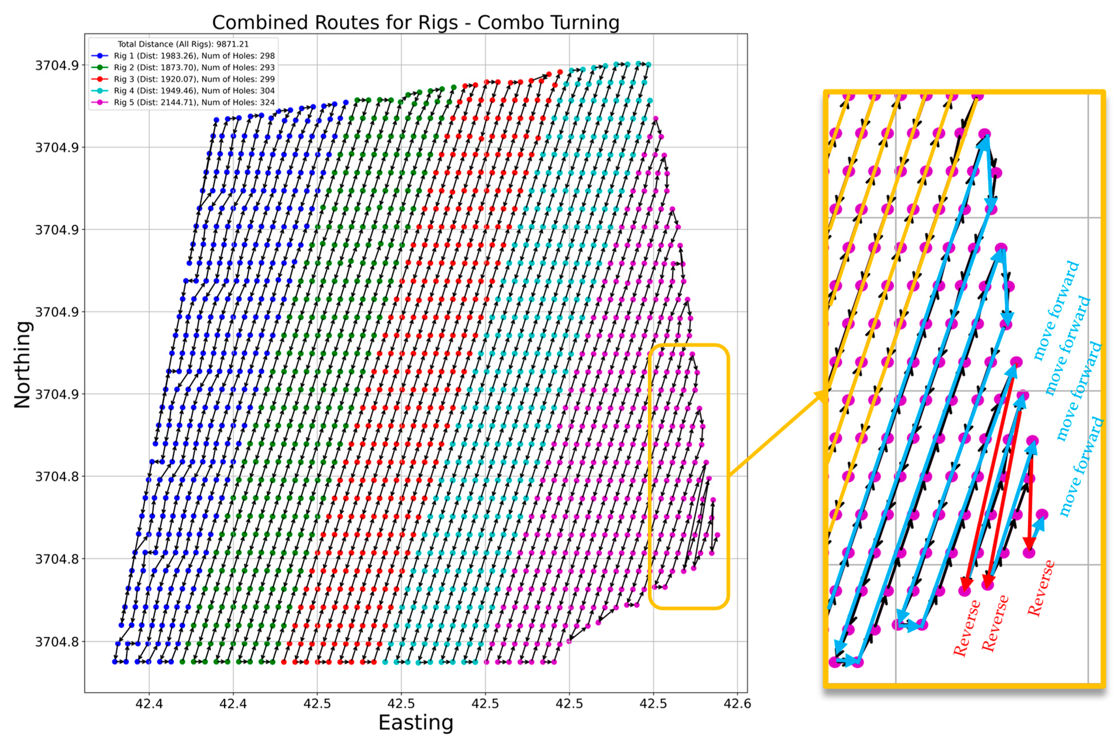
Figure 17 presents the results of the Combo manoeuvre implementation based on the MEC criteria. The algorithm assigned Continuous turning to all rigs except Rig 5 and Rig 1, which, after executing several three-point turns, switched to zig-zag manoeuvres for the final three routes. In these cases, the rig reversed to the starting points of the subsequent routes to continue drilling. In Figure 17, blue arrows represent forward movement with Continuous turning, where the rig transitions directly to the next route from the nearest end, minimising tramming distance. Red arrows labelled “Reverse” indicate zig-zag manoeuvres, where the rig moves backwards to reposition for the next route.
Figure 17.
The result of path generation using MEC criterion and Combo manoeuvre.
From a distance perspective, the Combo setting has a minimal impact on the overall travel distance. For the pattern shown in Figure 17, the total distance increased slightly from 9781.58 m (Continuous turning) to 9871.21 m, representing a marginal 1% increase (approximately 90 m). However, this small trade-off resulted in significantly improved rig manoeuvrability, reduced tramming time, and overall enhancement in operational efficiency.
4.3. Deviation Penalty Score
As demonstrated in the previous sections, the algorithm could generate multiple rig movement patterns for a single drilling layout—up to 16 variations—by altering the AoA, start/end points, and manoeuvring strategies. However, to proceed with execution, a single optimal pattern needed to be selected. The two principal criteria guiding this selection were (1) Total travel distance and (2) Ease of rig movement. The second criterion encompassed several sub-parameters, including
- The degree of misalignment from ideal straight-line paths,
- The number of individual routes,
- The number of segments (i.e., transitions between adjacent holes), and
- The number of turning events.
To quantify the degree of directional misalignment, this study introduced a novel metric called the Deviation Penalty Score (DPS), which provides a measurable indicator of path smoothness and alignment consistency. The DPS is a quantitative metric designed to evaluate how consistently the direction of route segments aligns with a specified target slope direction. It penalises angular deviations from the ideal trajectory defined by the AoA, thereby serving as an indicator of directional smoothness in rig movement. Equation (4) shows the equation for the calculation of DPS for each movement pattern:
where
- −
- is the target direction (in degrees)
- −
- is the direction of segment i (in degrees)
- −
- is the number of segments
DPS increases with greater misalignment and is particularly sensitive to significant directional errors, making it suitable for evaluating directional smoothness in path-planning and segment routing tasks.
Since the number of segments (i.e., the small routes between two holes) varied across different movement patterns, a normalised DPS was used to enable more accurate comparisons. The normalised DPS was calculated as shown in Equation (5).
4.4. Distance Reduction to Time Reduction
In the mining industry, time is a critical parameter, often used to evaluate operational efficiency and monitor changes across various processes. While this study initially assessed the effectiveness of the proposed algorithm through reductions in travel distance, this metric alone may not fully reflect its practical relevance to industry stakeholders. Therefore, it became essential to convert the observed distance savings into time savings, particularly in the context of the drilling cycle.
To estimate time reductions, this study employed the average rig tramming speed under the assumption that the rig operated at a consistent speed regardless of tramming direction or AoA. Based on field data, the average tramming speed across all rigs was calculated to be 0.52 km/h, as shown in Table 1. The conversion of distance savings to time reductions relied on the project-average tramming speed (0.52 km/h), derived from field records. These recorded times already accounted for real-world factors, including manoeuvres, reversing, ground conditions, and rig interactions. However, as detailed component-level data were unavailable, the estimated time savings are approximate and subject to uncertainty from these variable influences.
Table 3 presents the predicted tramming times for each rig along the optimised paths, calculated using maximum average, minimum average, and total average speed for the project values. The results indicate a notable variation—up to 50% difference—between tramming times calculated with the highest and lowest recorded speeds, highlighting the significant impact of tramming speed on overall tramming duration.
Table 3.
Predicted tramming time for rigs in the developed drill rigs paths.
According to Table 1, the total tramming time for manually driven routes was approximately 41.32 h. In contrast, the optimised paths generated by the proposed algorithm reduced this time to 18.98 h (Table 3), based on the average tramming speed, a reduction of approximately 54% in total tramming time. Given that drilling was conducted across both day and night shifts, tramming time reduction equalled almost one full day of the total 12-day project duration. This translated to saving nearly one full day, shortening the overall calendar project duration by ~8%. To assess the sensitivity of the predicted time savings to this assumption, a ±20% variation around the project-average speed was evaluated. For the optimised total distance of 9.871 km, the predicted tramming time ranged from 23.73 h at 0.416 km/h (−20%) to 15.82 h at 0.624 km/h (+20%), compared to 18.98 h at 0.52 km/h. Relative to the measured manual tramming time (41.32 h), this corresponded to a tramming-time reduction range of 42.6% to 61.7% (baseline 54.1%). In terms of calendar project duration (12 days), the implied reduction was ~6% to ~9% (baseline ~8%). These results indicate that the projected schedule benefit remains substantial under reasonable speed variability.
Notably, if drilling operations had been restricted to day shifts only, the time savings achieved through the algorithm would represent a significantly higher proportion of the total project duration, further underscoring the method’s practical benefits. Moreover, improved project management can further reduce overall project duration by minimising rig fuel consumption and the frequency of refuelling, decreasing mechanical wear and service requirements, and reducing path conflicts that contribute to idle time.
5. Discussion
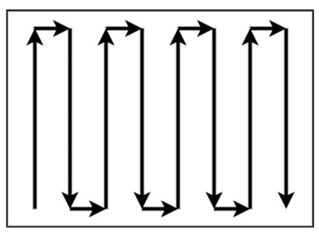
In this study, the developed system could identify the optimal routes possible for drilling. However, the question arises as to whether the results guarantee optimality in the problem, considering its NP-hard nature in computational complexity. Path planning for drill rigs resembles complete coverage path planning, where the drilling pattern can be treated as a uniform-cost grid due to the consistent burden and spacing. Several studies have demonstrated that in uniform-cost grids, when the problem is coverage path planning, the Serpentine (boustrophedon) path, as shown in Figure 18, is optimal due to its systematic coverage and minimal redundancy [23,24]. From a theoretical perspective, the optimality argument presented here is conceptual and conditional, rather than a formal proof in the strict sense of algorithmic logic. In uniform-cost grids with complete coverage requirements, serpentine (boustrophedon) paths are known to be distance-optimal due to their systematic coverage and minimal redundancy. This result is well established in the coverage path planning literature and provides a theoretical lower bound for problems that exhibit uniform spacing and consistent traversal costs.
Figure 18.
Example of the Serpentine (boustrophedon) path with back and forth movement [25].
Applying these facts to drill pattern optimisation, this suggests that the most efficient paths are those formed by parallel straight-line sequences of holes, connected through switch-row turning manoeuvres. Building upon this observation, a new variant of the algorithm developed in this study eliminated the use of DT and instead directly searched for the shortest possible combination of single-direction routes.
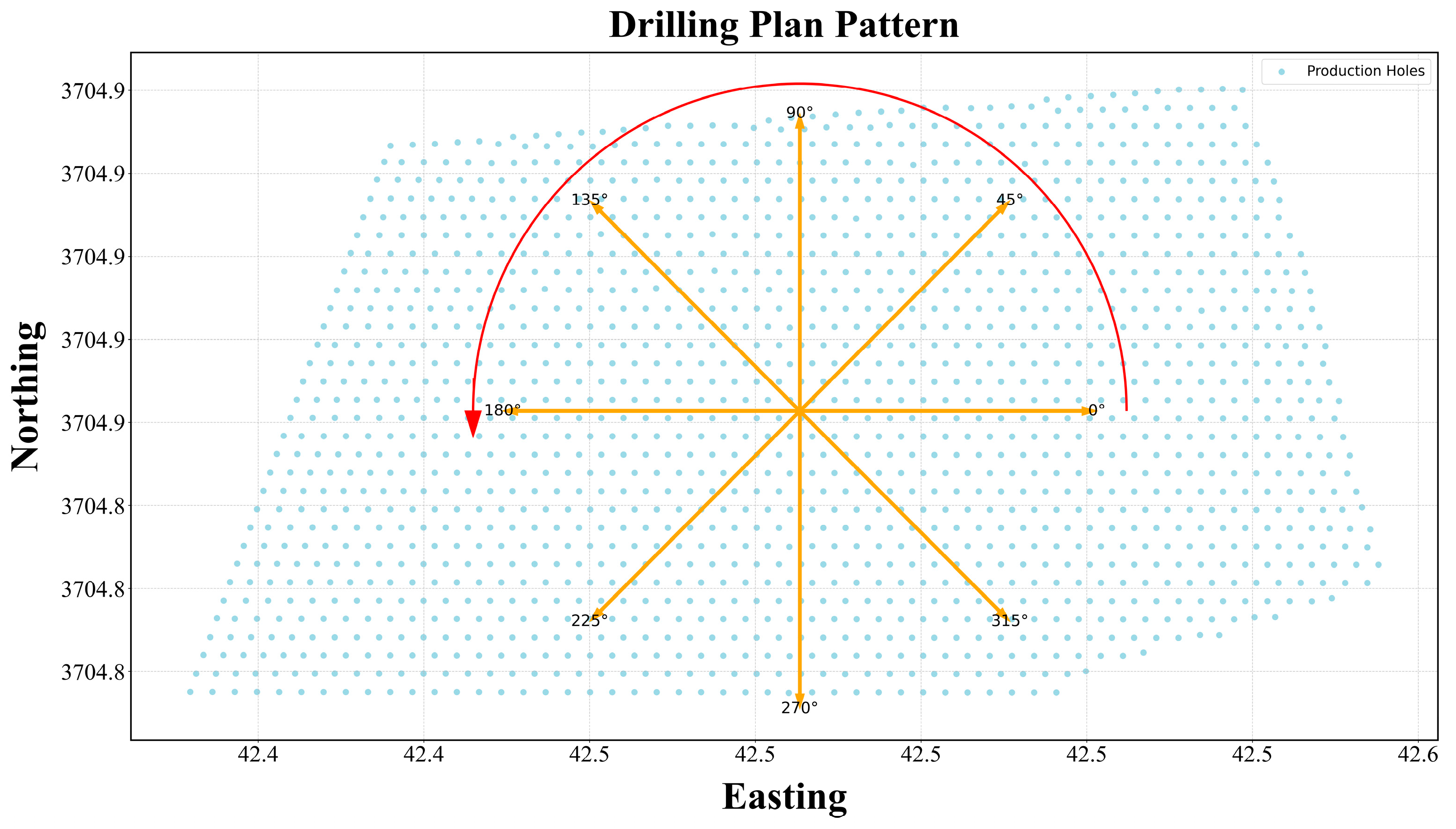
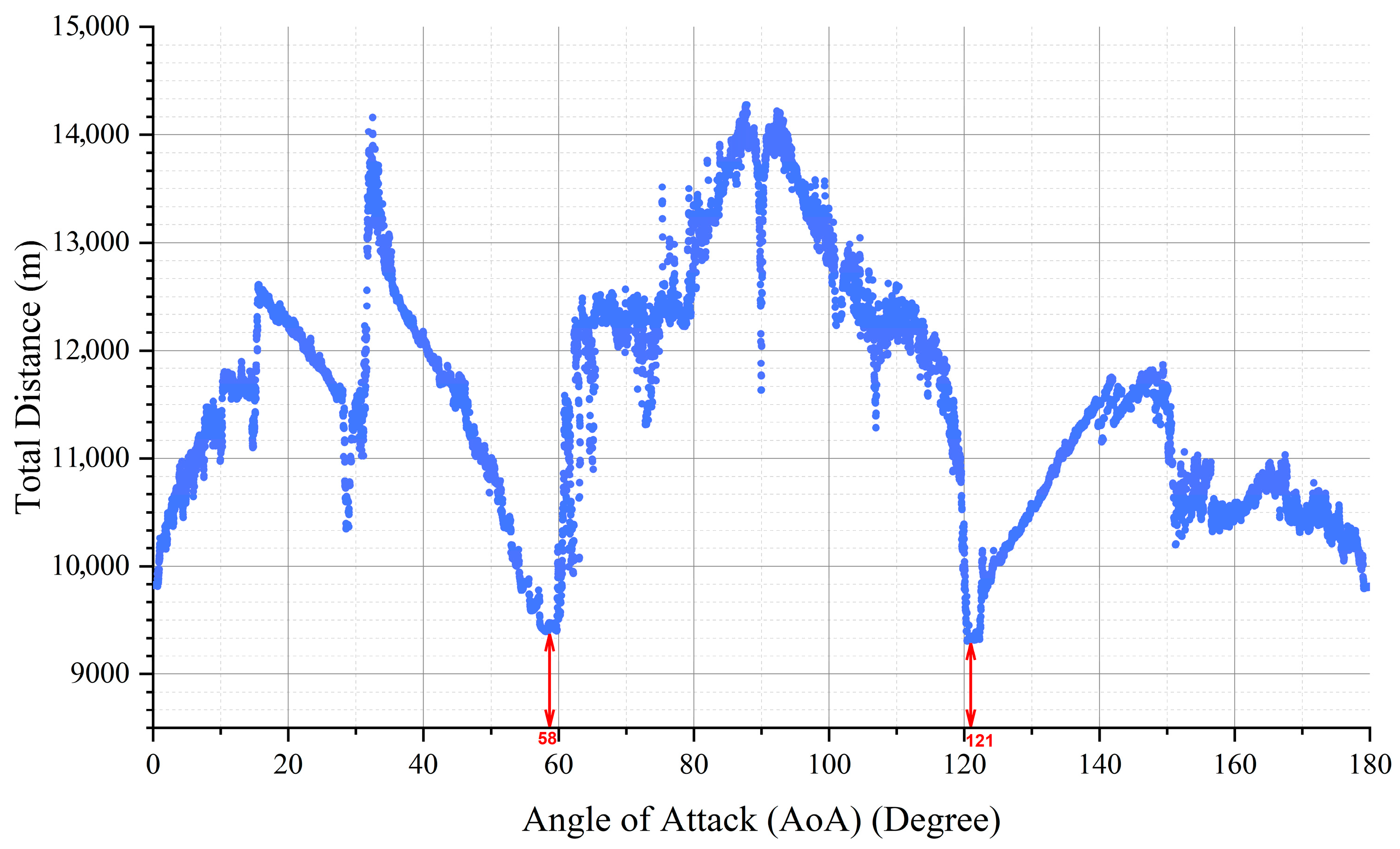
To achieve this, the new algorithm systematically evaluated all possible AoAs by rotating the AoA from 0° to 180° in increments of 0.01° and generated Serpentine paths, resulting in a total of 18,000 AoA scenarios. For each angle, the developed algorithm attempted to construct the most compact, continuous paths aligned with that orientation. The schematic illustration in Figure 19 visualises the concept of this rotational search, demonstrating how the algorithm identifies the optimal single-route alignment for the given drilling pattern.
Figure 19.
Schematic presentation of global serpentine path search from 0° to 180° in increments of 0.01°.
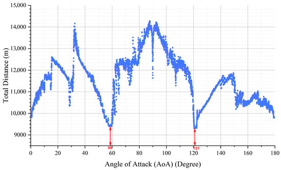
After executing the modified algorithm and comparing the 18,000 scenarios, the optimal AoAs were identified as angles of around 58.4° and 121° (see Figure 20), which coincide with the direction previously obtained using the DT approach (58.63° and 301.37°). However, the run time for this global search was around 200 min, while the main approach using the DT for AoA search was less than 2 s. This outcome confirms the efficacy of the developed search method for identifying optimal paths for drill rigs in a drilling pattern. As shown in Figure 20, the total distance varied with the AoA, reaching its minimum at approximately 58.4° and 121°.
Figure 20.
Final result of 18,000 global serpentine path search from 0° to 180° in increments of 0.01°.
It is important to note that the DT method inherently produces a mesh of small, regularly repeated triangles, provided that the burden and spacing are consistent throughout the pattern. Within each triangle, the three principal edges correspond to the burden, spacing, and hypotenuse between them. Paths aligned with any direction other than these primary edges inherently involve greater total distances. Therefore, by comparing and selecting the shortest among these three edge orientations, the algorithm ensures convergence toward the globally minimum travel distance across the drilling pattern.
However, the selection of the optimal drilling path should not be based solely on total distance. Other parameters, such as the number of route transitions, turning distances, and directional consistency, may significantly influence the final selection. These factors were discussed in detail in Section 4.
Table 4 provides a comparative summary of key performance indicators for three path configurations generated at different AoAs. The metrics include total tramming and turning distances, number of individual routes and segments, and the DPS, both in absolute and normalised form. Together, these indicators help to assess the overall efficiency, smoothness, and practicality of each path configuration.
Table 4.
Summary of the developed algorithm’s performance in path generation on the given drilling pattern.
The ranking method proposed by Zorlu et al. [26], which has been widely applied in previous studies [27,28], was employed in this study to identify the most suitable drilling path. Given the critical importance of both total distance and the DPS in evaluating drilling efficiency, these two parameters were assigned double weight relative to the other influencing factors in the ranking process. After ranking the parameter values for each generated pattern, the configuration with an angle of attack of +58.63° emerged as the most favourable option for path planning in the studied drilling pattern.
New features in the current study, such as path orientation and variable starting points, are critical factors that were not addressed in the previous study by Elinas [9], and there is currently no solution available in the industry for them. Although the applied GA in the study generated a shorter path, it lacked a deeper understanding of the operational constraints specific to drilling. In particular, it did not incorporate directional or starting-point constraints, which are essential in real-world scenarios where the rig’s entry point or alignment relative to the free face may be restricted due to access roads, ramps, or active work zones. Furthermore, as an evolutionary optimisation technique, GA cannot guarantee global optimality, which limits its reliability for high-stakes operational planning.
The presence of multiple zig-zagging paths, diagonal jumps, and disconnected zones in the studied cases suggests that rig movement is not fully optimised. This could lead to increased non-productive time (NPT), greater fuel consumption, and higher mechanical wear. However, by incorporating the MEC-based Combo turning strategy, this study expanded upon previous works by offering a more comprehensive search for optimised drilling paths.
The reduction in tramming time by over 50%, leading to an 8% decrease in total project duration, highlights the strong potential of the proposed algorithm for commercial implementation. Moreover, the algorithm’s low computational time—producing multiple scenarios in under two minutes—is a key strength of this algorithm. This efficiency makes it highly suitable for replanning during project execution in response to unforeseen issues.
Despite these promising results, this study is subject to certain limitations. First, it assumes uniform terrain and rig performance, which may not reflect real-world variability such as slope gradients or surface irregularities. While the proposed method achieves substantial improvements over these real-world sequences, unmodelled operational disturbances, such as rig breakdowns, variable ground conditions, blasting delays, or safety reassignments, may have influenced the executed paths. Detailed records of such events were unavailable, preventing their incorporation into the current retrospective model. Future work will address these complexities by integrating real-time operational data and developing dynamic replanning capabilities to enhance robustness in field conditions. Additionally, the use of as-drilled data instead of design coordinates may introduce deviations that affect route optimisation accuracy, although the algorithm has been shown to be able to manage the deviations to some extent. Moreover, the rigs are treated as identical in type and capability, which may not be the case in diverse operational fleets.
The proposed framework deterministically achieves the minimum tramming distance possible for a given set of hole coordinates. This distance optimality is guaranteed by exhaustive alignment search via DT and complete boustrophedon path construction. However, final path selection among candidate alignments uses multi-criteria ranking (distance, turning effort, and Deviation Penalty Score), rendering the overall solution a high-quality deterministic heuristic.
The methodology presented is applicable to a wide range of drilling layouts, including larger or more complex patterns. The algorithm’s scalability was tested on multi-rig setups and maintained consistent performance. However, additional work is needed to validate its effectiveness in irregular or topographically constrained environments, where additional parameters such as elevation change must be considered.
6. Conclusions
This research introduces a robust, deterministic path planning framework tailored for autonomous drill rigs in open-pit mining. The developed algorithm successfully integrates spatial pattern recognition, angle of attack analysis, and manoeuvrability constraints to generate optimised tramming paths that minimise travel distance while maintaining directional consistency. The choice of DT as the core of this deterministic framework is particularly well-suited to open-pit mining drill rig path planning, as it efficiently generates a maximal set of non-overlapping triangles from point coordinates, revealing inherent geometric structures in drilling patterns without requiring exhaustive combinatorial searches. Unlike AI-based evolutionary algorithms (e.g., Genetic Algorithms), which suffer from stochastic variability, leading to inconsistent optimality across runs, and high computational demands (often requiring minutes to hours even for small patterns due to hyperparameter sensitivity), the proposed DT-based approach delivers consistent, globally optimal results in seconds. This advantage arises from exploiting local geometric properties (e.g., burden, spacing, and hypotenuse edges) to identify straight, minimal-distance paths, aligning perfectly with the practical constraints of mining environments, where real-time replanning is essential amid dynamic conditions such as equipment failures or terrain changes.
By incorporating a novel use of the DPS and the MEC, the algorithm balances path smoothness with operational efficiency, allowing dynamic selection between Continuous and zig-zag turning strategies based on real conditions.
The results demonstrate that the proposed method significantly improves both efficiency and practicality in drilling operations. Compared to manually driven routes, the optimised paths reduced tramming time by more than 50%, translating to meaningful time, fuel, and cost savings. Additionally, by testing a comprehensive range of 18,000 angles of attack and applying rigorous ranking criteria, the method ensures a solution that is not only efficient but also contextually optimal.
While the proposed framework deterministically achieves the minimum travel distance among the evaluated geometric alignments, the overall solution should be interpreted as a high-quality deterministic heuristic for path planning, rather than a strict mathematical proof of global optimality for arbitrary drilling patterns.
Beyond its technical performance, this framework offers high scalability and adaptability, making it applicable to a range of drilling layouts and multi-rig scenarios. While the current study assumes uniform terrain and rig specifications, future developments can extend its functionality by incorporating elevation models, real-time rig telemetry, and environmental impact metrics such as CO2 emissions. Ultimately, this work contributes a critical step toward fully automated, data-driven drill rig management, enabling safer, faster, and more sustainable mining operations.
However, this method’s effectiveness relies on relatively uniform hole spacing; limitations include reduced accuracy in highly irregular or non-planar patterns, where additional preprocessing (e.g., for elevation data) may be needed to maintain applicability.
Future studies should incorporate terrain and elevation data to improve path accuracy, especially on uneven ground. Using real-time rig data and automated decision-making tools could help adjust the path during operations. It would also be useful to require the algorithm to consider rig-specific features, like how sharply each rig can turn. Finally, future works should estimate how much the optimised paths can lower overall project costs. Moreover, future studies could investigate the impact of path optimisation on reducing the carbon footprint of the mining industry and its potential to enhance Environmental, Social, and Governance (ESG) compliance. Calculating the savings in fuel and time could provide a clearer picture of the method’s environmental and economic benefits.
Author Contributions
M.S.: Conceptualisation, Data curation, Investigation, Methodology, Software, Writing—original draft, review and editing, Visualisation, Validation; R.S.F.: Conceptualisation, Funding acquisition, Project administration, Supervision, Writing—review and editing, E.T.: Conceptualisation, Funding acquisition, Project administration, Supervision, Writing—review and editing; J.G.: Supervision, Project administration, Funding, Writing—review and editing. All authors have read and agreed to the published version of the manuscript.
Funding
This work was supported by the Resources Technology and Critical Minerals Trailblazer, the Commonwealth Government through the Trailblazer Universities Program, and FLANDERS [Project Number: RES-SE-WAS-VT-68376-2].
Institutional Review Board Statement
Not applicable.
Informed Consent Statement
Not applicable.
Data Availability Statement
The datasets presented in this article are not readily available because the data are part of an ongoing study. Requests to access the datasets should be directed to roohollah.shiranifaradonbeh@curtin.edu.au.
Acknowledgments
This publication is supported by the Resources Technology and Critical Minerals Trailblazer and the Commonwealth Government through the Trailblazer Universities Program. The authors would also like to acknowledge Flanders Electric of Australia for their support in conducting this project.
Conflicts of Interest
Author Joshua Goodwin is employed by FLANDERS. The remaining authors declare that the research was conducted in the absence of any commercial or financial relationships that could be construed as a potential conflict of interest. The authors declare that this study received funding from Flanders. The funder had the following involvement with the study: preparing the historical database for the project, supervising the Curtin researcher, providing technical consultations, and organising site visits for further data collection. The authors declare that this study received funding from FLANDERS. The funder had the following involvement with the study: data collection, review of this article, and the decision to submit it for publication.
References
- Bag, D. Optimization of Capital Costs and Carbon Footprint in Open Cast Mining. SSRN eLibrary 2022, 3862475. Available online: https://papers.ssrn.com/sol3/papers.cfm?abstract_id=3862475 (accessed on 14 January 2026). [CrossRef] [Scilit]
- Matysek, A.L.; Fisher, B.S. Productivity and Innovation in the Mining Industry; BAE Research Report; BAEconomics Pty Ltd.: Canberra, Australia, 2016. [Google Scholar]
- Parreira, J. An Interactive Simulation Model to Compare an Autonomous Haulage Truck System with a Manually-Operated System. Ph.D. Thesis, University of British Columbia, Vancouver, BC, Canada, 2013. [Google Scholar] [CrossRef] [Scilit]
- Afeni, T.B. Optimization of drilling and blasting operations in an open pit mine—The SOMAIR experience. Min. Sci. Technol. (China) 2009, 19, 736–739. [Google Scholar] [CrossRef] [Scilit]
- Hamodi, H. Reliability and Life Cycle Cost Modelling of Mining Drilling Rigs. Ph.D. Thesis, Luleå Tekniska Universitet, Luleå, Sweden, 2014. [Google Scholar]
- Kokkinis, A.; Frantzis, T.; Skordis, K.; Nikolakopoulos, G.; Koustoumpardis, P. Review of Automated Operations in Drilling and Mining. Machines 2024, 12, 845. [Google Scholar] [CrossRef] [Scilit]
- Fan, X.; Singh, S.; Oppolzer, F.; Nettleton, E.; Hennessy, R.; Lowe, A.; Durrant-Whyte, H. Integrated planning and control of large tracked vehicles in open terrain. In Proceedings of the 2010 IEEE International Conference on Robotics and Automation, Anchorage, AK, USA, 3–7 May 2010; pp. 4424–4430. [Google Scholar] [CrossRef] [Scilit]
- Samaei, M.; Faradonbeh, R.S.; Topal, E. A Systematic Review of Equipment Path Planning Systems in Mining: Insights for Fully Automating the Open-Pit Drill Rigs. WA School of Mines (WASM), Curtin University, Kalgoorlie, WA 6430, Australia. Min. Metall. Explor. (MME), 2025; submitted.
- Elinas, P. Multi-goal planning for an autonomous blasthole drill. In Proceedings of the International Conference on Automated Planning and Scheduling, Thessaloniki, Greece, 19–23 September 2009; pp. 342–345. [Google Scholar] [CrossRef] [Scilit]
- Applegate, D.L. The Traveling Salesman Problem: A Computational Study; Princeton University Press: Princeton, NJ, USA, 2006; Volume 17. [Google Scholar] [CrossRef] [Scilit]
- Hoos, H.H.; Stϋtzle, T. Stochastic local search. In Handbook of Approximation Algorithms and Metaheuristics; Chapman and Hall/CRC: Boca Raton, FL, USA, 2018; pp. 297–307. [Google Scholar]
- Steyn, R. Drilling of a 60 m Deep Bench Is Always Fun. Available online: https://www.linkedin.com/posts/reinhardt-steyn-51b8628a_drilling-of-a-60m-deep-bench-is-always-fun-activity-7181159022023061505-LtR6?utm_source=share&utm_medium=member_desktop&rcm=ACoAABlrE7kBSlyvUiTTE5CYSsPPpo1uQhdYsGc (accessed on 14 January 2026).
- Sakcak, B.; Bascetta, L.; Ferretti, G.; Prandini, M. Sampling-based optimal kinodynamic planning with motion primitives. Auton. Robot. 2019, 43, 1715–1732. [Google Scholar] [CrossRef] [Scilit]
- Schleich, D.; Behnke, S. Search-based planning of dynamic MAV trajectories using local multiresolution state lattices. In Proceedings of the 2021 IEEE International Conference on Robotics and Automation (ICRA), Xi’an, China, 30 May–5 June 2021; pp. 7865–7871. [Google Scholar] [CrossRef] [Scilit]
- Samaei, M.; Shirani Faradonbeh, R.; Topal, E.; Goodwin, J. Path optimisation for drill rigs: A step toward full automation in mining. In Proceedings of the 2025 Resource Operator Conference (ROC 2025), University of Southern Queensland, Brisbane, Australia, 6–7 February 2025; pp. 124–131. [Google Scholar] [CrossRef]
- Adeshara, K.; Elangovan, V. Face recognition using PCA integrated with Delaunay triangulation. arXiv 2020, arXiv:2011.12786. [Google Scholar] [CrossRef] [Scilit]
- Rodríguez, N.; Silveira, R.I. Implementing data-dependent triangulations with higher order Delaunay triangulations. In Proceedings of the 24th ACM SIGSPATIAL International Conference on Advances in Geographic Information Systems, San Francisco, CA, USA, 31 October–3 November 2016; pp. 1–10. [Google Scholar] [CrossRef] [Scilit]
- Dechaumphai, P.; Phongthanapanich, S.; Sricharoenchai, T. Combined Delaunay triangulation and adaptive finite element method for crack growth analysis. Acta Mech. Sin. 2003, 19, 162–171. [Google Scholar] [CrossRef] [Scilit]
- Zhang, J.; Xu, Z.; Liu, H.; Zhu, X.; Lan, B. An Improved Hybrid Ant Colony Optimization and Genetic Algorithm for Multi-Map Path Planning of Rescuing Robots in Mine Disaster Scenario. Machines 2025, 13, 474. [Google Scholar] [CrossRef] [Scilit]
- Bellman, R. Dynamic programming. Science 1966, 153, 34–37. [Google Scholar] [CrossRef] [Scilit] [PubMed]
- Dreyfus, S. Richard Bellman on the birth of dynamic programming. Oper. Res. 2002, 50, 48–51. [Google Scholar] [CrossRef] [Scilit]
- Cormen, T.H.; Leiserson, C.E.; Rivest, R.L.; Stein, C. Introduction to Algorithms; MIT Press: Cambridge, MA, USA, 2022. [Google Scholar]
- Choset, H.; Pignon, P. Coverage path planning: The boustrophedon cellular decomposition. In Field and Service Robotics; Springer: London, UK, 1998; pp. 203–209. [Google Scholar] [CrossRef] [Scilit]
- Champagne Gareau, J.; Beaudry, É.; Makarenkov, V. Fast and optimal branch-and-bound planner for the grid-based coverage path planning problem based on an admissible heuristic function. Front. Robot. AI 2023, 9, 1076897. [Google Scholar] [CrossRef] [Scilit] [PubMed]
- Fevgas, G.; Lagkas, T.; Argyriou, V.; Sarigiannidis, P. Coverage path planning methods focusing on energy efficient and cooperative strategies for unmanned aerial vehicles. Sensors 2022, 22, 1235. [Google Scholar] [CrossRef] [Scilit] [PubMed]
- Zorlu, K.; Gokceoglu, C.; Ocakoglu, F.; Nefeslioglu, H.; Acikalin, S. Prediction of uniaxial compressive strength of sandstones using petrography-based models. Eng. Geol. 2008, 96, 141–158. [Google Scholar] [CrossRef] [Scilit]
- Samaei, M.; Alinejad Omran, M.; Keramati, M.; Naderi, R.; Shirani Faradonbeh, R. Assessing the shear strength of sandy soil reinforced with polyethylene-terephthalate: An AI-based approach. Earth Sci. Inform. 2024, 17, 4507–4526. [Google Scholar] [CrossRef] [Scilit]
- Samaei, M.; Massalow, T.; Abdolhosseinzadeh, A.; Yagiz, S.; Sabri, M.M.S. Application of soft computing techniques for predicting thermal conductivity of rocks. Appl. Sci. 2022, 12, 9187. [Google Scholar] [CrossRef] [Scilit]

Disclaimer/Publisher’s Note: The statements, opinions and data contained in all publications are solely those of the individual author(s) and contributor(s) and not of MDPI and/or the editor(s). MDPI and/or the editor(s) disclaim responsibility for any injury to people or property resulting from any ideas, methods, instructions or products referred to in the content. |
© 2026 by the authors. Licensee MDPI, Basel, Switzerland. This article is an open access article distributed under the terms and conditions of the Creative Commons Attribution (CC BY) license.