


Abstract
Tunnel excavation in ground comprising a soft upper stratum and a hard lower stratum posed significant challenges, particularly during invert construction using drilling-and-blasting methods, which could disturb the surrounding rock and the installed support system. To address these issues, this study evaluates the feasibility of an alternative support scheme that eliminates the invert by employing expanded arch feet, thereby utilizing the self-bearing capacity of the underlying hard stratum. Both physical model tests and numerical simulations were conducted to compare the structural performance of a conventional lining with an invert against the proposed expanded arch foot lining. Based on the strain measurements and earth pressure cell readings from the physical model tests, together with the internal force and contact pressure results obtained from the numerical simulations, the axial force, bending moment, and contact pressure between the lining and surrounding rock were compared for the two lining schemes. The safety factors were further calculated using the axial force and bending moment at representative sections. The results showed qualitatively consistent trends between the tests and simulations. Compared with the conventional invert lining, the expanded arch foot lining increased the axial force and bending moment at the arch foot and sidewall by 7.95% and 29.60%, respectively, while slightly reducing those at the crown by 4.44% and 3.09%. This indicates that part of the structural demand is transferred from the crown to the arch foot and sidewall, where the enlarged sections provide greater bearing capacity. The contact pressure distributions of the two lining schemes were different. Owing to its closed structural form, the conventional invert lining produced a more favorable contact pressure condition at the sidewall. In contrast, the expanded arch foot lining showed higher safety factors at the arch foot and sidewall, with increases of 89.80% and 36.00% in the model tests and more than 140% in the numerical simulations. Meanwhile, the internal force distributions of the two lining schemes remained generally comparable. These findings indicated that the lining with expanded arch feet provided sufficient structural capacity at critical sections and could serve as a feasible alternative to the conventional lining with an invert, while avoiding the construction-related disadvantages associated with invert excavation.
1. Introduction
As the development of transportation infrastructure continues to advance in China, highway tunnels have begun to extend into regions with more complex geological conditions [1]. This issue was particularly prominent in the southeastern coastal areas and southwestern mountainous regions of China, where tunnels have increasingly been constructed in upper soft and lower hard composite ground [2,3,4,5,6,7,8,9,10]. This type of ground is typically characterized by loose, weak overburden overlying hard bedrock. The pronounced contrast in the mechanical properties of the rock mass poses considerable challenges to tunnel construction [8,11,12,13,14,15,16,17,18,19]. The mechanical properties of the stratum beneath the arch foot play an important role in tunnel deformation and support performance. For example, Yuan et al. [20] investigated an upper-hard/lower-weak geological condition and showed that the weak lower stratum beneath the arch foot provided unfavorable support, contributing to settlement and convergence deformation. This geological configuration differs from that investigated in the present study. Here, the tunnel is located in upper-soft/lower-hard composite ground, where the lower stratum has comparatively greater stiffness, strength, and integrity. Therefore, an important question is whether the bearing resistance of this competent lower stratum can be effectively utilized to optimize the tunnel-bottom support structure.
The invert is a reverse arch structure installed at the tunnel bottom. It improves the stress state of the upper support structure and is a key component of the tunnel lining system [21,22,23,24]. However, in composite ground consisting of a weak upper layer and a competent lower rock layer, the conventional invert lining has several limitations. The underlying hard rock usually has high bearing capacity and strength. It can satisfy the foundation bearing requirements of the tunnel structure [25]. Under such geological conditions, the continued use of an invert does not fully utilize the self-bearing capacity of the underlying hard rock. It also increases construction complexity and slows construction progress [26]. In addition, invert construction is technically complicated and costly. A conservative invert design may further reduce economic efficiency. Therefore, for tunnels constructed in ground with favorable lower rock conditions, the necessity of installing an invert requires further investigation.
In recent years, studies on tunnel bottom structures have mainly focused on invert omission, invert excavation, tunnel bottom deformation, and reinforcement measures. Some studies discussed the necessity of invert installation under different surrounding rock conditions. They also proposed alternatives such as flat-bottom structures, plain concrete, and grouted bolts [27,28,29,30]. Other studies showed that inverted excavation disturbed the original equilibrium of the surrounding rock and affected the stability of the support system [31]. Meanwhile, floor heave, invert uplift, and invert cracking have also been investigated through field monitoring, model tests, and numerical simulations [24,32,33,34]. Various reinforcement measures have been proposed to control tunnel bottom deformation. These measures include grouting, anchor cables, compressible layers, drainage improvement, and invert replacement [35,36,37]. These studies provide important references for understanding tunnel bottom behavior. However, most of them focus on deformation treatment or reinforcement of damaged tunnel bottoms. For tunnels in strata with a weak upper layer and a hard lower layer, limited research has examined how to use the self-bearing capacity of the lower hard rock while ensuring the safety of the lining affected by the upper weak stratum.
The main contribution of this study was to propose and verify an expanded arch foot lining as an alternative to the conventional invert lining for highway tunnels in upper soft and lower hard composite ground. Physical model tests and numerical simulations were conducted to compare the two lining schemes. The comparison focused on axial force, bending moment, safety factor, and contact pressure between the lining and surrounding rock. This study aimed to clarify the load transfer mechanism of the expanded arch foot lining and to assess whether it could provide sufficient structural capacity while avoiding the construction drawbacks associated with the invert.
2. Project Overview
This study was based on a tunnel under construction in Shandong Province, which was characterized by typical upper-soft and lower-hard composite ground. Specifically, the section ranging from the sidewalls to the crown consisted of fractured Class V surrounding rock, while the rock mass below the sidewalls and the tunnel invert was classified as Class IV and III, exhibiting better integrity and higher strength. Although the hard rock layer at the tunnel bottom possessed good self-stabilizing capacity, the construction of the invert using the drill-and-blast method posed a risk to structural safety, as the vibrations induced by blasting were prone to disturbing the installed support and the surrounding rock. Furthermore, the invert construction process itself was complicated and costly.
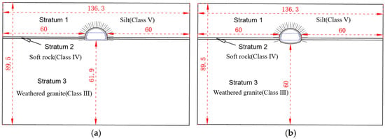
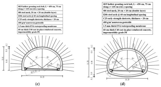
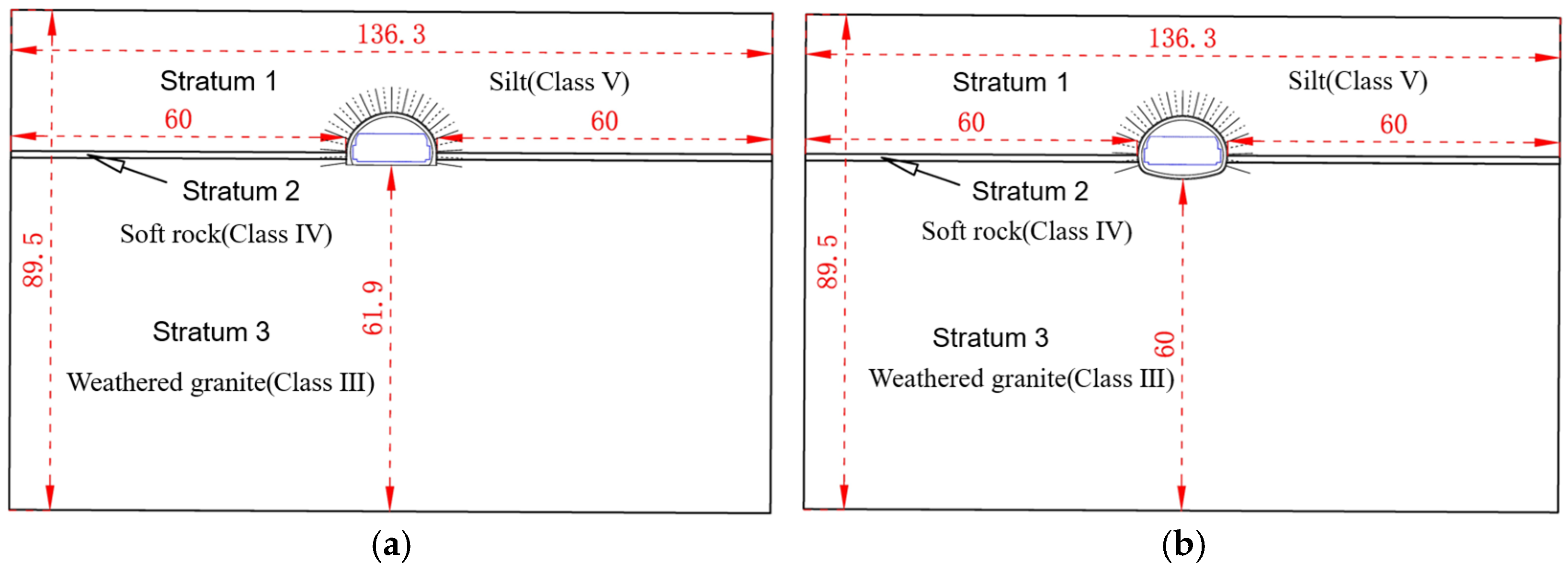
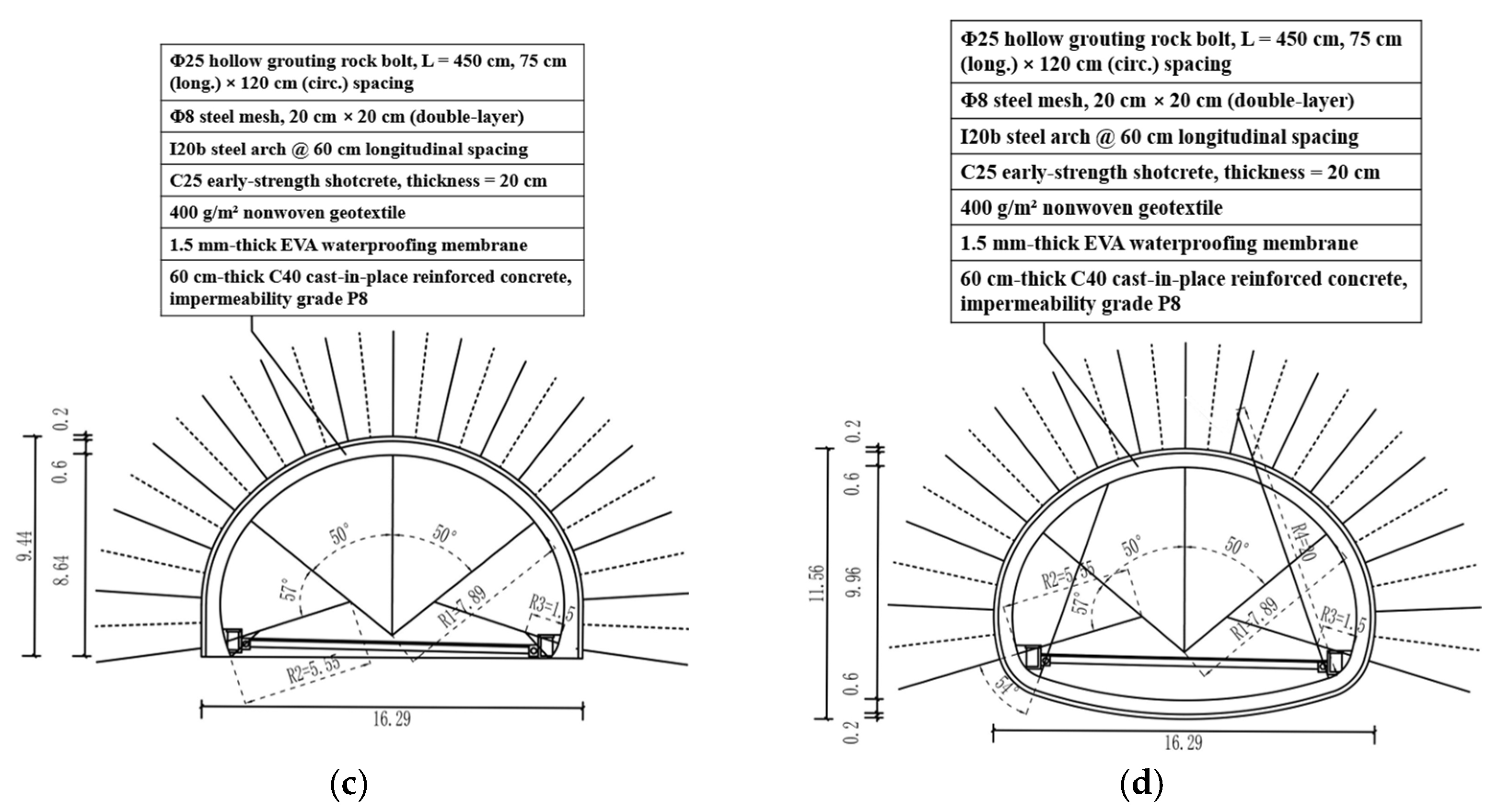
To take advantage of the bearing capacity of the hard rock layer beneath the tunnel bottom, the tunnel floor support system was optimized. The geometrical dimensions and lining parameters of the optimized scheme were adopted from the original design to ensure a consistent comparison between the two schemes. Accordingly, the optimized design differs from the original design only in the tunnel-bottom support configuration, where the conventional invert was replaced by expanded arch feet, as shown in Figure 1. The primary support consists of 0.20 m-thick C25 shotcrete, and the secondary lining consists of 0.60 m-thick C40 cast-in-place reinforced concrete. In this scheme, the intact hard rock layer at the tunnel bottom was retained and used as a permanent bearing structure. The excavation and blasting procedures required for invert construction were therefore avoided. This reduced construction disturbance to both the surrounding rock and the installed support. It was also expected to shorten the construction period and reduce project cost. To verify the feasibility and rationality of the optimized lining scheme, laboratory physical model tests were conducted.
Figure 1.
Schematic of stratum and lining configuration. (a) Stratum for the expanded arch foot support scheme; (b) Stratum for the inverted arch support scheme; (c) Expanded arch foot support scheme (unit: m); (d) Inverted arch support scheme (unit: m).
3. Physical Model Test
3.1. Test Similarity Ratios and Similar Materials
By considering both the dimensions of the test equipment and the requirement to ensure similarity between the model and prototype values in terms of key mechanical properties, geometric and density similarity ratios of and were designed, respectively. The similarity ratios for the key physical parameters are presented in Table 1.
Table 1.
Selection of similarity ratio for model tests.
The material mixtures were determined based on the geological investigation report of the project. The manufacturability of the model materials, the similarity ratios of the mechanical parameters, and the property contrast between the soft and hard strata were also considered. Class V surrounding rock was simulated using a mixture of barite powder, quartz sand, and petroleum jelly at a mass ratio of 8:5:0.6 [38]. Class IV surrounding rock was simulated using a mixture of barite powder, fine sand, gypsum, dishwashing liquid, and water at a mass ratio of 25:15:4:1:4 [39]. Class III surrounding rock was simulated using a mixture of barite powder, quartz sand, high-strength gypsum, laundry detergent, and water at a mass ratio of 43.5:29:20:1.5:6 [40]. The parameters of the prototype surrounding rock and the model materials are presented in Table 2.
Table 2.
Similar material parameters of the surrounding rock.
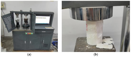
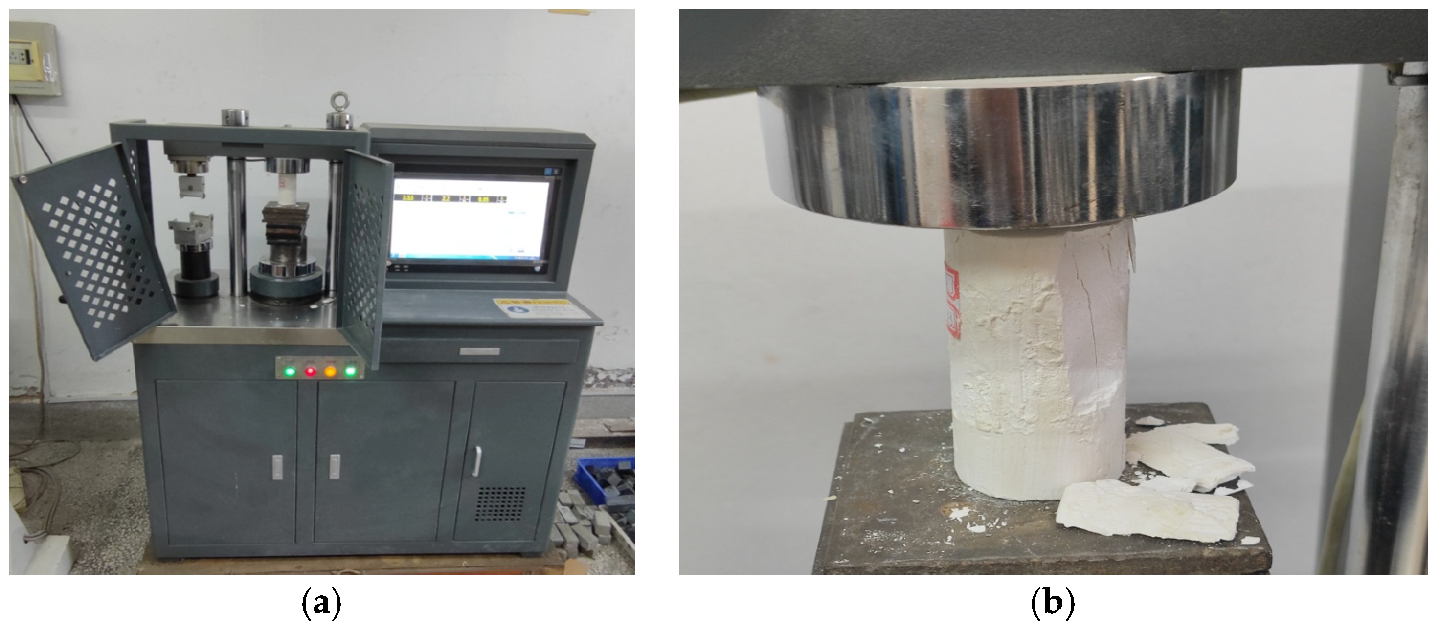
The prototype lining in the supporting project was made of C40 cast-in situ concrete. To determine an appropriate mixture proportion for the model lining material, a single-factor test series was conducted by varying the water-to-gypsum ratio. The uniaxial compressive strength of specimens with different water-to-gypsum ratios was measured, as shown in Figure 2. For each ratio, three specimens were prepared, and the average strength was used as the representative value. The test results are listed in Table 3. Considering the geometric similarity ratio of 1:50, the similarity requirements for compressive strength and elastic modulus, and the orthogonal test results, a water-to-gypsum ratio of 1:1 was selected for preparing the model material of the lining.
Figure 2.
Uniaxial compression test. (a) Compression testing machine; (b) Uniaxial compression test.
Table 3.
Single-factor test results for gypsum specimens.
3.2. Model Test Systems
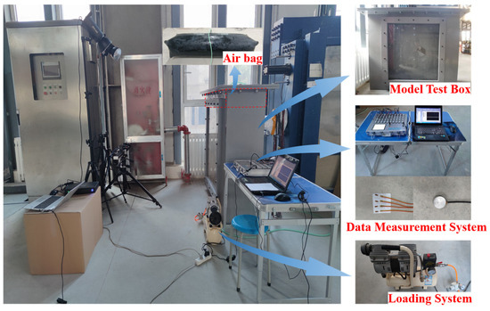
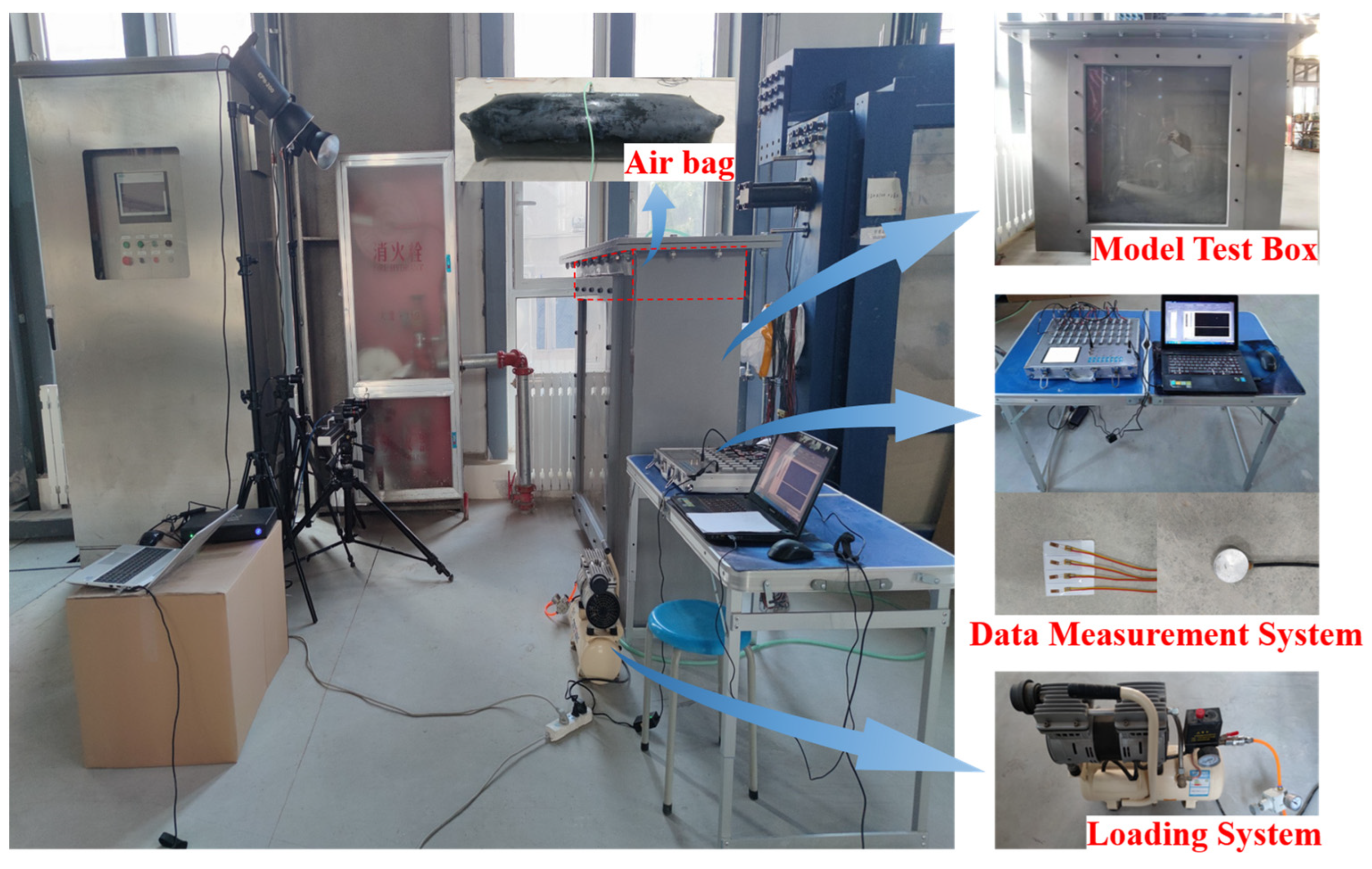
The model test system primarily consisted of three components: the model test box, the loading system, and the data measurement system, as shown in Figure 3.
Figure 3.
Components of the model test system.
- (1)
- Model Test Box: The test box was fabricated by welding 20 mm-thick steel plates. It had dimensions of 1.4 m in height, 0.4 m in width, and 1.6 m in length. The roof of the box served as a reaction frame for the loading system. A plexiglass panel was embedded in the center of the front side of the box to facilitate the observation of the test phenomena.
- (2)
- Loading System: This system comprised an OTS-550 type air compressor and an airbag. The airbag was positioned between the model surface and the box roof, in close contact with the roof to utilize it for reaction. The airbag was laterally confined by the box walls. During the test, the airbag was inflated by the air compressor, and the air pressure was monitored and controlled in real-time using the attached pressure gauge. In this way, the vertical loading on the model was achieved.
- (3)
- Data Measurement System: This system was employed to monitor the internal forces within the lining and the surrounding rock pressure during the test. Specifically, the strains in the lining were measured using 120-5AA type resistance strain gauges. These gauges had a base size of 9 mm × 4 mm and a grid size of 5 mm × 2.9 mm, with a sensitivity of 2 ± 1% and a resistance value of 120 Ω. The surrounding rock pressure was measured using micro-earth pressure cells. All sensors were installed on the surface of the tunnel model, and the data were collected in real-time by a YBY-4010 stress–strain test and acquisition system.
3.3. Test Plan and Procedure
To verify the feasibility of the lining structure with expanded arch feet, two groups of comparative model tests were designed for different support configurations. In the prototype tunnel, the overburden depth above the tunnel crown was 20 m. According to the geometric similarity ratio of 1:50, the corresponding overburden depth in the model was 40 cm. However, due to the dimensional limitation of the test box, the upper 10 cm of the model ground could not be reproduced. Therefore, a uniform airbag load was applied on the model surface to compensate for the missing overburden pressure. The equivalent vertical pressure was calculated as q = γh = 18 kN/m3 × 0.10 m = 1.8 kPa, where γ denoted the unit weight of the corresponding model material and ℎ denoted the thickness of the missing model ground. Accordingly, an airbag pressure of 1.8 kPa was applied in the tests. The use of uniform surcharge or controlled static loading has been widely adopted in tunnel model tests to reproduce overburden stress. Li [41] developed a large-scale tunnel model test system that can apply controlled static and dynamic loads to simulate the in situ stress field. Similar surcharge loading methods have also been used in reduced-scale tunnel tests to study tunnel deformation and surrounding pressure under external loading. This study supports the feasibility of using a properly calculated uniform surcharge to compensate for the missing overburden in physical model tests.
The specific test procedure was as follows:
- (1)
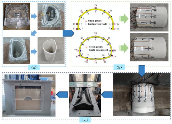
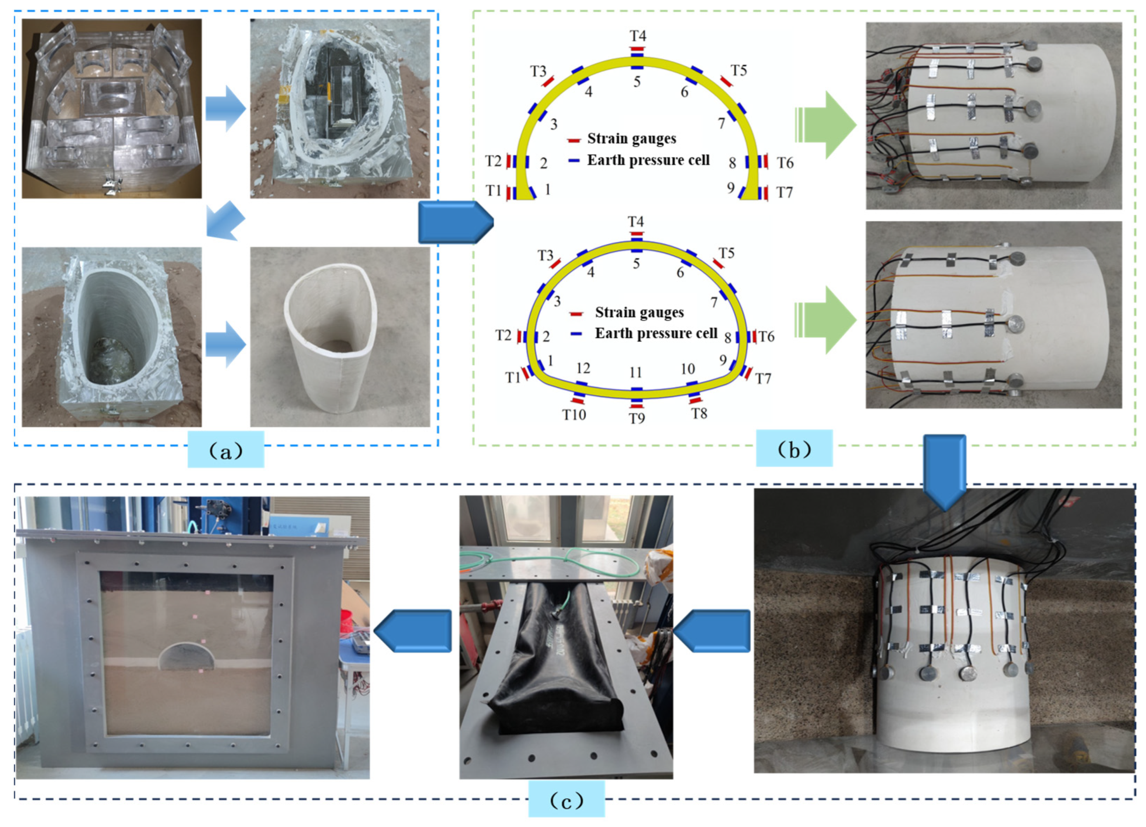
- Model fabrication and sensor installation: The tunnel lining models were cast using the analogous material ratios determined previously. After demolding, strain gauges were bonded to the inner and outer surfaces of the lining at the designed locations. Earth pressure cells were installed on the outer surface of the lining to measure the contact pressure between the lining and the surrounding rock. The sensors were installed at predetermined measurement locations according to the arrangement shown in Figure 4b. For both lining schemes, pressure cells T1–T7 were arranged at corresponding characteristic locations, namely the left arch foot, left sidewall, left haunch, crown, right haunch, right sidewall, and right arch foot, respectively. For the conventional invert lining, three additional pressure cells (T8–T10) were installed at the right invert, invert center, and left invert. Thus, the same pressure-cell numbers T1–T7 denote corresponding characteristic locations in the two lining models.Figure 4. Model test preparation. (a) Model casting; (b) Sensor installation; (c) Test box backfilling. Note: Blue arrows indicate the sequence of experimental preparation steps; green arrows indicate the correspondence between the schematic sensor layout and the actual sensor arrangement.
- (2)
- Surrounding rock backfilling and model placement: The analogous materials for the three classes of surrounding rock were prepared according to the test scheme. Layered backfilling was adopted. Each layer was compacted and left to stabilize before the next layer was placed. When the backfilled material reached the predetermined elevation, the lining model with preinstalled sensors was placed at the designated position. Backfilling then continued until the design height was reached.
- (3)
- Loading system installation and testing: After backfilling was completed, the loading airbag was installed on top of the model (Figure 4c), and the roof plate of the model box was repositioned and secured. The load was applied according to the test scheme, and the strain and contact pressure data were recorded simultaneously.
Furthermore, in the physical model tests, the excavation and support processes were simplified. The complete CD excavation sequence, blasting disturbance, and time-dependent installation of the primary support and secondary lining were not reproduced. Instead, the tests focused on the mechanical response of the completed lining structures after excavation and support installation. The surrounding rock layers were constructed according to the geological profile, and the conventional invert lining and the expanded arch foot lining were embedded in the model to represent the final support states of the two schemes. Therefore, the physical model tests were mainly used to compare the structural performance of the two completed lining schemes under the same simplified geological and loading conditions. The construction sequence and stress release caused by excavation were further considered in the numerical simulation by using the CD excavation procedure and modulus reduction method. In this way, the physical model tests and numerical simulations complemented each other. The former provided an experimental comparison of the two completed lining schemes, whereas the latter reproduced the staged excavation and support process in greater detail.
3.4. Main Test Results
For clarity, unless otherwise stated, all results presented in the following physical model test analyses have been converted from the measured model-scale quantities to prototype-equivalent values according to the similarity relationships listed in Table 1. The reported contact pressures are prototype-equivalent stresses and are expressed in kPa. The lining axial forces and bending moments are normalized to a unit longitudinal width of 1 m and are therefore reported in kN/m and kN·m, respectively. Strain and safety factor are dimensionless quantities. In contrast, the material properties listed for the model materials in Table 2 and Table 3 are model-scale values unless they are explicitly identified as prototype values.
3.4.1. Internal Force Analysis of Lining in Physical Model Tests
The internal force distribution of the lining was calculated from the strain data obtained in the tests. Strain gauges were installed on both the inner and outer surfaces of the lining model, and the measured strain data were used to calculate the corresponding internal forces. The calculation formula is given as follows:
where E is the elastic modulus of the material, is the strain on the inner surface, is the strain on the outer surface, b is the length of the lining, which is set to 1 m in this study, and h is the thickness of the lining. In this study, compressive axial force N is defined as positive and tensile axial force as negative. For the bending moment M, inward bending of the lining is defined as negative and outward bending as positive. The units of axial force and bending moment are kN and kN·m, respectively.
The equations used to calculate the internal force were derived from the Euler–Bernoulli beam theory. The derivation was based on the plane-section assumption and linear elastic constitutive behavior. Under these assumptions, the strain distribution through the lining thickness is linear. The average strain of the inner and outer surfaces represents the axial strain of the section. The strain difference between the two surfaces represents the bending-induced strain. Therefore, the axial force and bending moment can be obtained from the stress resultants over the lining section [42].
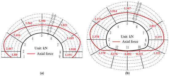
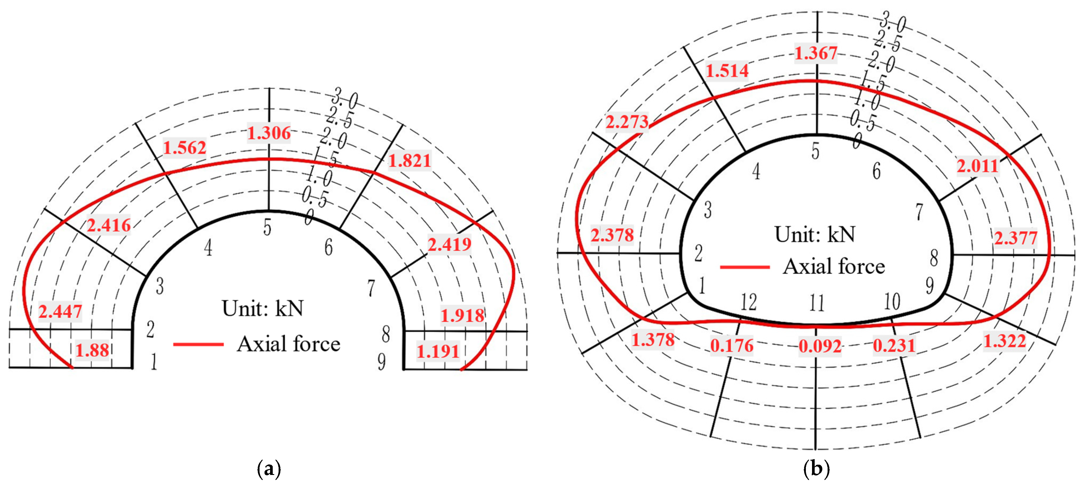
The axial force distributions of the two lining schemes are shown in Figure 5. Although slight differences in axial force are observed between corresponding positions on the two sides of the secondary lining, the overall distribution pattern is approximately symmetric. These differences are mainly attributed to unavoidable variability in the physical model test, including minor deviations during model preparation and measurement, and do not affect the overall distribution characteristics. Both linings exhibited positive axial force values, indicating that the lining structures were mainly under compression. Due to the limited number of strain monitoring points, the exact locations of the maximum axial forces were not captured in these tests. Nevertheless, the measured results showed that larger axial forces developed from the arch foot to the haunch, with the peak value occurring between the sidewall and the arch waist. The axial force values at various sections of the expanded arch foot lining and the lining with an invert did not differ significantly. For the lining with an invert, the axial forces at positions 1-left arch foot, 2-left sidewall, 3-left arch waist, and 4-left haunch were 1.38 kN, 2.38 kN, 2.27 kN, and 1.51 kN, respectively. For the expanded arch foot lining, the corresponding values were 1.88 kN, 2.45 kN, 2.42 kN, and 1.56 kN, representing increases of 36.20%, 2.90%, 6.61%, and 3.31%, respectively, compared to the lining with an invert. However, at position 5-crown, the axial forces for the lining with an invert and the expanded arch foot lining were 1.37 kN and 1.31 kN, respectively, with the expanded arch foot lining showing a decrease of 4.38% compared to the lining with an invert.
Figure 5.
Axial force distribution in secondary lining. (a) Expanded arch foot support scheme; (b) Inverted arch support scheme. 1-left arch foot, 2-left sidewall, 3-left arch waist, 4-left haunch, 5-crown, 6-right haunch, 7-right arch waist, 8-right sidewall, 9-right arch foot, 10-right arch bottom, 11-arch bottom, and 12-left arch bottom.
In regions other than the crown, the conventional invert lining developed slightly lower axial forces than the expanded arch foot lining. This indicated that the construction of the invert had a certain improving effect on the axial force conditions in most parts of the lining. However, the reduction was less than 10%, suggesting that the improvement was limited. At the crown, the expanded arch foot lining developed a lower axial force than the conventional invert lining. This indicated a more favorable mechanical response at this location. In addition, the hard rock below the tunnel bottom had good self-stabilizing capacity. Therefore, relatively small axial forces were observed in the invert region of the conventional invert lining, such as 10-right arch bottom, 11-arch bottom, and 12-left arch bottom. Overall, based on the axial force response of the lining in the model tests, the expanded arch foot lining was considered feasible.
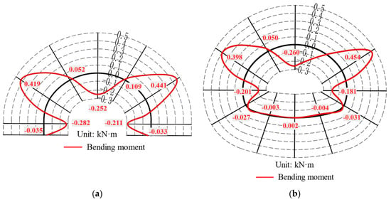
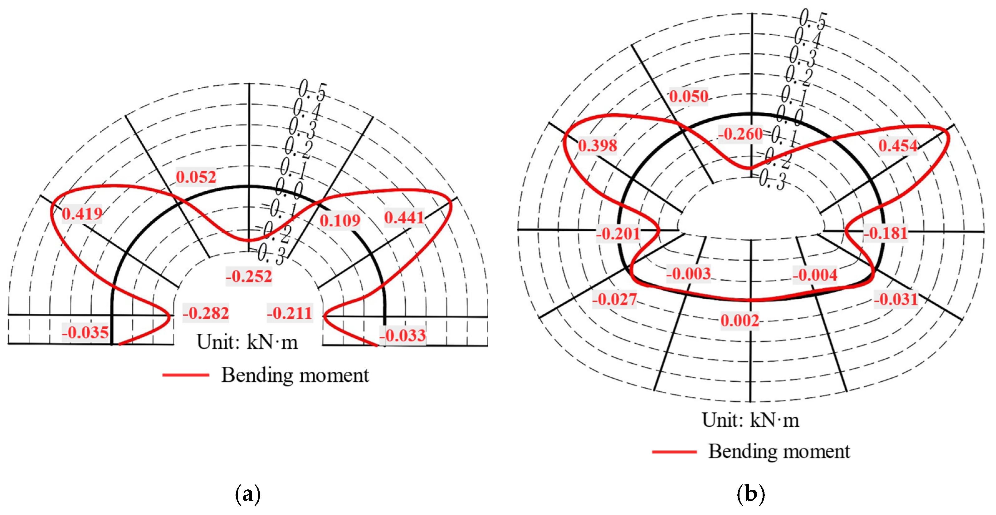
Figure 6 shows the bending moment distributions of the two lining schemes, and the monitoring positions are the same as those shown in Figure 5. The bending moments were nearly symmetrically distributed. Both linings developed negative bending moments at the crown and sidewalls, indicating inward bending of the tunnel. Positive bending moments developed from the arch waist to the haunch, indicating outward bending of the tunnel. The maximum negative bending moment occurred at the crown, whereas the maximum positive bending moment occurred at the arch waist. For the lining with an invert, the bending moments at positions 1-left arch foot, 2-left sidewall, 3-left arch waist, and 4-left haunch were −0.03 kN·m, −0.20 kN·m, 0.40 kN·m, and 0.05 kN·m, respectively. For the expanded arch foot lining, the corresponding values were −0.04 kN·m, −0.28 kN·m, 0.42 kN·m, and 0.05 kN·m, representing increases of 33.33%, 40.00%, and 5.00%, respectively, compared to the lining with an invert. However, at position 5-crown, the bending moments for the lining with an invert and the expanded arch foot lining were −0.26 kN·m and −0.25 kN·m, respectively, with the expanded arch foot lining showing a decrease of 3.84% compared to the lining with an invert.
Figure 6.
Bending moment distribution in secondary lining from physical model tests. (a) Expanded arch foot support scheme; (b) Inverted arch support scheme.
The difference in internal force distribution between the two lining schemes was attributed to their different structural configurations and load transfer mechanisms. In the conventional invert lining, the invert connects the two sidewalls and forms a closed structural system, which helps redistribute part of the load through the tunnel bottom. In contrast, the expanded arch foot lining does not rely on a closed invert. The enlarged arch foot sections transferred more load to the competent lower hard stratum. As a result, the axial force and bending moment at the arch foot and sidewall increased to some extent, whereas the structural demand at the crown decreased. This response indicated that the expanded arch foot lining changed the load transfer path. The support was provided jointly by the lower hard stratum and the enlarged arch foot sections, rather than by a closed invert system. Nevertheless, the overall internal force distribution remained comparable to that of the conventional invert lining. Therefore, under the investigated geological conditions, omitting the invert did not cause an unfavorable redistribution of internal forces.
3.4.2. Safety Factor Analysis of Lining in Physical Model Tests
The safety factor has been an important parameter reflecting the safety and working conditions of a tunnel, ensuring the safety reserve that should be maintained under normal design and construction conditions. When checking the strength of a lining section, the calculated safety factor should not be less than the value specified in the relevant code [43]. The safety factor for the lining can be calculated using Equations (3) and (4):
where is the safety factor, is the axial force in the lining, is the longitudinal bending coefficient of the component, for tunnel linings , is the eccentricity influence coefficient of axial force, is the ultimate compressive strength of concrete, is the ultimate tensile strength of concrete, is the section width (m), h is the section thickness (m), and is axial force eccentricity distance.
The lining thickness and the geometry of the expanded arch foot were included in the calculation through the sectional area and moment of inertia of each representative section. Therefore, the safety factor reflects not only the internal force state but also the actual sectional dimensions of the two lining schemes.
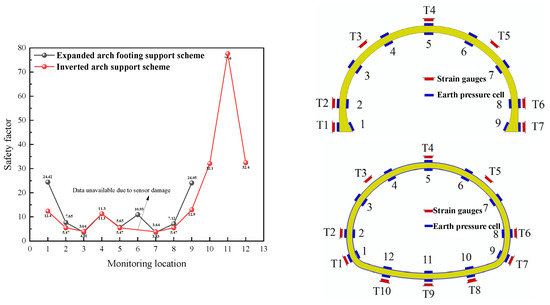
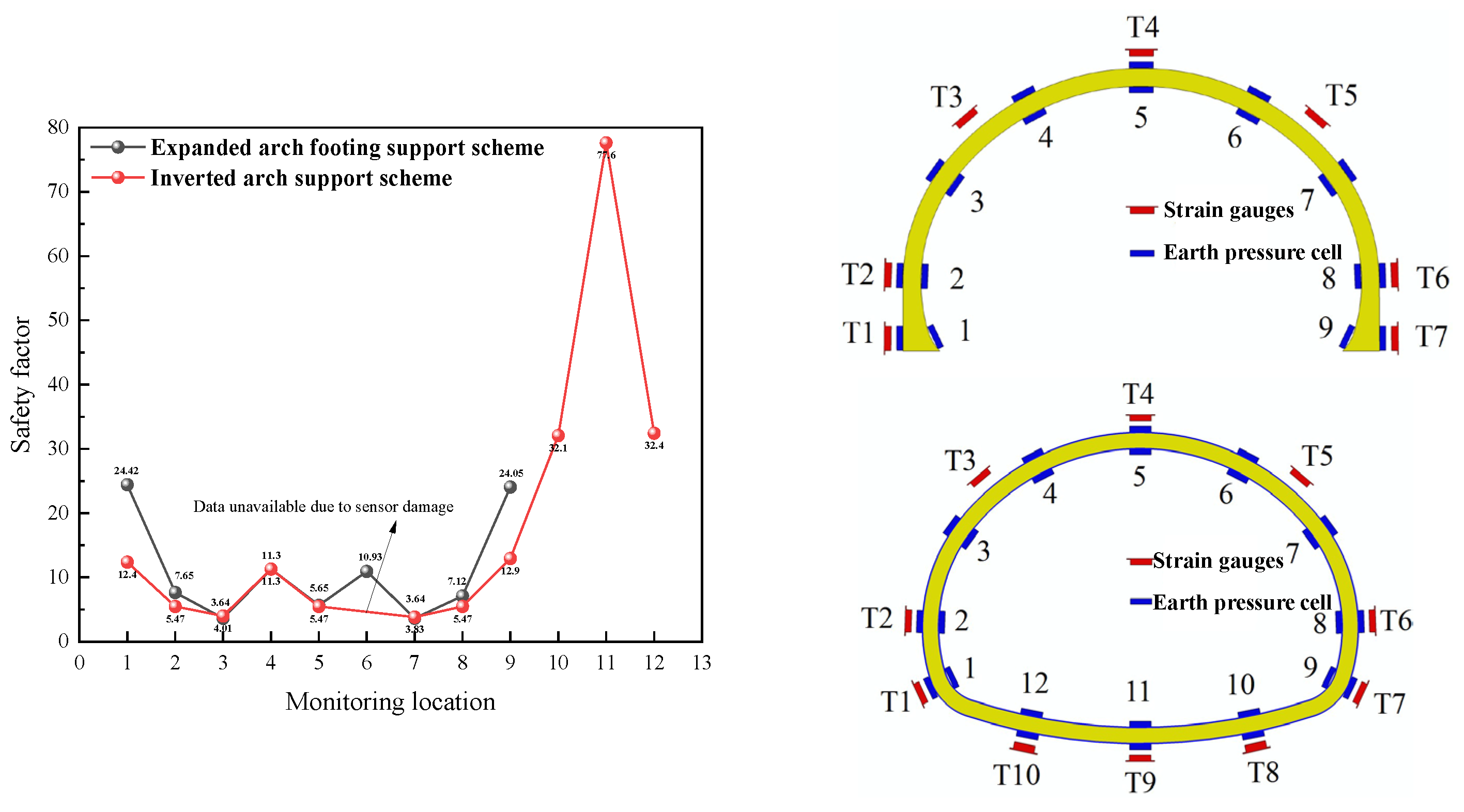
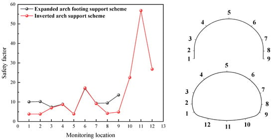
As shown in Figure 7, the safety factors of the expanded arch foot lining were generally higher than, or close to, those of the conventional invert lining. The improvement was most evident at the arch foot and sidewall. This was mainly attributed to the enlarged sections at these locations. Taking the left side as an example, the safety factors at the left arch foot and left sidewall increased from 12.88 and 5.48 for the conventional invert lining to 24.45 and 7.42 for the expanded arch foot lining, corresponding to increases of 89.82% and 35.40%, respectively. These results indicated that the expanded arch foot improved the safety reserve in the lower part of the lining, which became critical after the invert was omitted.
Figure 7.
Distribution of lining safety factors from physical model tests. 1-left arch foot, 2-left sidewall, 3-left arch waist, 4-left haunch, 5-crown, 6-right haunch, 7-right arch waist, 8-right sidewall, 9-right arch foot, 10-right arch bottom, 11-arch bottom, and 12-left arch bottom.
For the crown, arch waist, and haunch, the safety factors of the two schemes were generally similar. These sections were important for evaluating lining safety. Specifically, for the conventional invert lining, the safety factors at the left arch waist, left haunch, and crown were 3.92, 11.70, and 5.64, respectively. For the expanded arch foot lining, the corresponding values were 3.73, 11.33, and 5.74. Compared with the conventional invert lining, these values represented a decrease of 4.85%, a decrease of 3.16%, and an increase of 1.77%, respectively. These differences were small. They indicated that omitting the invert did not significantly reduce the safety reserve of the main load-bearing sections. All calculated safety factors met the code requirements. Therefore, the expanded arch foot lining achieved comparable safety performance at the crown, arch waist, and haunch, while providing a much larger safety reserve at the arch foot and sidewall.
The safety factor results further demonstrated the mechanical advantage of the expanded arch foot lining. After the invert was omitted, the axial force and bending moment at the arch foot and sidewall increased to some extent. However, the enlarged sections provided greater sectional capacity and stiffness at these locations. As a result, the safety factors at the arch foot and sidewall were much higher than those of the conventional invert lining. For the crown, arch waist, and haunch, the safety factors of the two schemes remained close. This indicated that invert omission did not reduce the safety reserve of the main upper part of the lining. In the conventional invert lining, the very large safety factor at the invert suggested an excessive safety reserve under the investigated geological conditions. Because the lower stratum consisted of competent hard rock with sufficient bearing capacity, the invert was not fully mobilized. Its use may therefore lead to a conservative and less economical design. Overall, the expanded arch foot lining provided a more reasonable distribution of structural safety reserve while satisfying the code requirements.
3.4.3. The Contact Pressure of the Lining
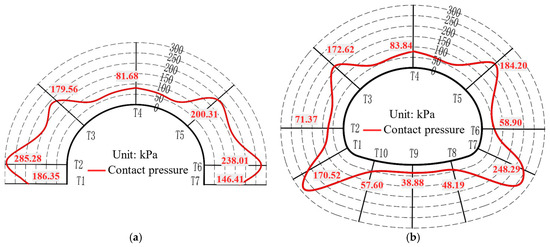
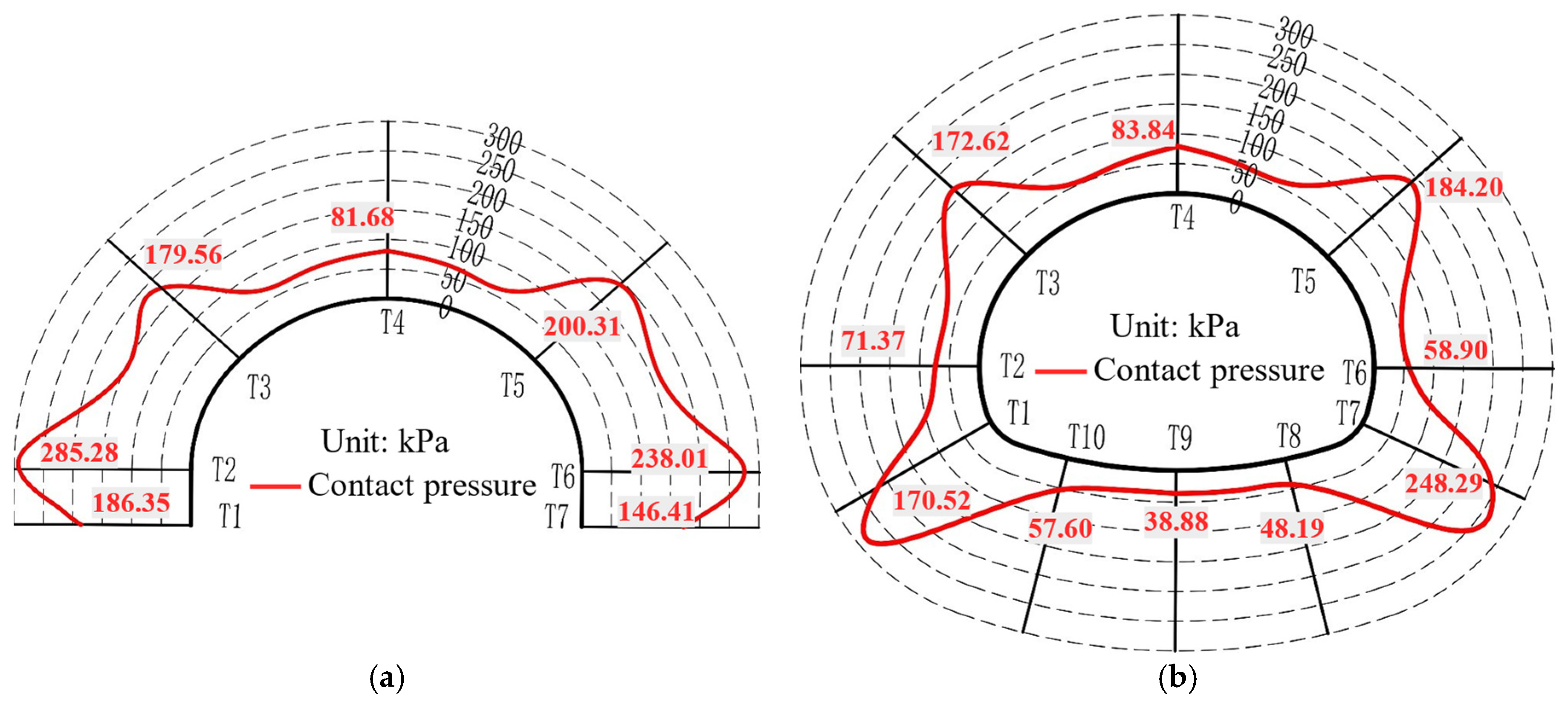
During the test, the surrounding rock transmitted pressure to the lining structure through contact, causing it to deform and generate internal forces. The contact pressure between the lining and the surrounding rock was measured by pressure cells arranged on the lining. These were numbered T1 to T7 on the expanded arch foot lining and T1 to T10 on the lining with an invert, as shown in Figure 8.
Figure 8.
Distribution of contact pressure. (a) Expanded arch foot support scheme; (b) Inverted arch support scheme. T1-left arch foot, T2-left sidewall, T3-left haunch, T4-crown, T5-right haunch, T6-right sidewall, T7-right arch foot, T8-right arch bottom, T9-arch bottom, and T10-left arch bottom. T1–T7 denote corresponding measurement locations in both support schemes, whereas T8–T10 are applicable only to the inverted arch support scheme.
The results showed that the contact pressures of both lining schemes were approximately symmetric. However, perfect symmetry was not achieved because the pressure cells could not be installed in exactly symmetrical positions and because of other experimental limitations. Taking the left half of the lining as an example, the expanded arch foot lining showed the maximum contact pressure at the left sidewall, followed by the left haunch, whereas the minimum value occurred at the crown. For the conventional invert lining, the maximum contact pressure occurred at the arch foot, followed by the haunch, and the minimum value occurred at the invert. For the conventional invert lining, the contact pressures at T1-left arch foot, T2-left sidewall, T3-left haunch, and T4-crown were 170.52, 71.37, 172.62, and 83.84 kPa, respectively. The corresponding values for the expanded arch foot lining were 186.35, 285.28, 179.56, and 81.68 kPa. Compared with the conventional invert lining, the expanded arch foot lining increased the contact pressures at the arch foot, sidewall, and haunch by 9.28%, 299.72%, and 4.02%, respectively, but reduced the crown contact pressure by 2.58%.
The contact pressure results reflected the different interactions between the lining and the surrounding rock. The conventional invert lining forms a closed ring structure, which improves the contact condition at the sidewall and helps distribute the surrounding rock pressure through the invert. Therefore, the sidewall contact pressure condition was more favorable in the conventional invert lining. For the expanded arch foot lining, the load was mainly transferred to the lower hard stratum through the enlarged arch foot sections. The omission of the invert changed the contact pressure distribution at the sidewall. However, the differences at most other positions were limited. More importantly, the lower hard stratum provided a reliable bearing medium, and the expanded arch foot increased the contact and support capacity at the lower part of the lining. These results indicated that the expanded arch foot lining could maintain stable interaction with the surrounding rock without forming a closed invert system.
4. Numerical Simulation
4.1. Model Development
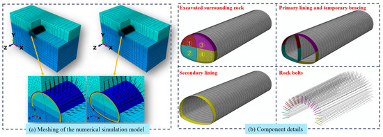
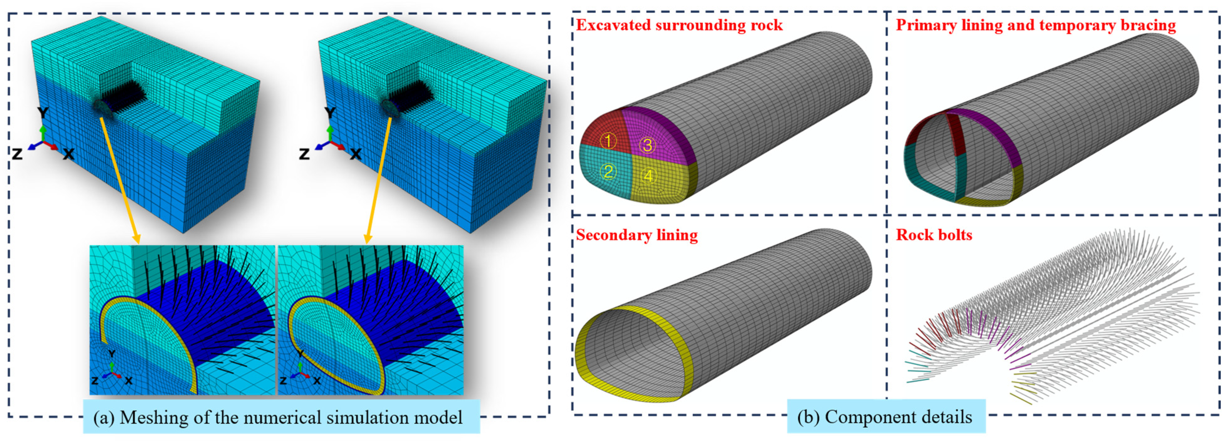
As shown in Figure 9, a three-dimensional finite-element model was established in ABAQUS to simulate the excavation and support process of the tunnel in upper-soft and lower-hard composite ground. Two support schemes were considered: the conventional lining with an invert and the proposed expanded arch-foot lining. Except for the tunnel-bottom configuration, the geometrical dimensions and support parameters were kept consistent between the two models.
Figure 9.
Numerical model overview. (a) Meshing of the numerical simulation model; (b) Component details.
The numerical model consisted of the surrounding rock, primary support, secondary lining, rock bolts, and temporary support. The three surrounding-rock strata were represented using the Mohr–Coulomb constitutive model, whereas the support components were assumed to behave as linear-elastic materials. The reinforcement and steel arches were not modelled separately; instead, their stiffness contribution was incorporated into the corresponding support components through equivalent elastic properties. The material parameters used in the analysis are summarized in Table 4.
Table 4.
Material parameters of key components in numerical simulation.
The primary support was represented by C25 shotcrete with the contribution of the steel arches incorporated through the equivalent stiffness, while the secondary lining was represented by C40 cast-in-place concrete. The rock bolts were ϕ25 hollow grouted bolts with a length of 4.5 m and a staggered arrangement. The secondary-lining thickness in the main lining section was 0.60 m, consistent with the prototype design. The local geometry of the expanded arch-foot region was modelled according to the dimensions shown in Figure 1.
The initial ground-stress state was established using the ABAQUS geostatic equilibrium procedure. Only the gravity-induced stress field was considered, whereas tectonic stress was neglected. Gravity was applied to the surrounding rock and support components with a gravitational acceleration of 9.8 m/s2. The initial equilibrium calculation resulted in negligible residual displacement before tunnel excavation. Groundwater and seepage effects were not considered in the present numerical analysis.
After geostatic equilibrium, the residual displacement was on the order of 10−12 m, indicating satisfactory establishment of the initial stress field. Contact was defined between the inner surface of the primary support and the outer surface of the secondary lining using a finite-sliding formulation. Hard contact was adopted in the normal direction, while tangential behavior was represented by Coulomb friction with a coefficient of 0.3. The rock bolts were constrained to the surrounding rock and primary support so that compatible deformation and load transfer could be represented.
The primary lining, temporary bracing, and surrounding rock were discretized using eight-node linear brick elements (C3D8R). The secondary lining was modeled using four-node quadrilateral shell elements (S4R), and the rock bolts were simulated using two-node linear truss elements (T3D2). A formal multi-level mesh-convergence study was not conducted in the original analysis; therefore, the adopted mesh should be regarded as a locally refined engineering discretization rather than a formally demonstrated convergence limit.
The construction process using the center diaphragm (CD) method was simulated through staged element activation and deactivation. The specific excavation sequence is as shown in Figure 9 from ① to ④. To approximately account for the partial stress release occurring ahead of support installation, a modulus-reduction method was adopted for the excavation zone. Before removal of the excavation elements, the elastic modulus of the material within the corresponding excavation zone was reduced by 40%, followed by support activation and excavation-element removal. Similar stiffness/modulus-reduction approaches have been adopted in previous numerical studies of tunnel excavation to represent the stress-release process [44,45,46]. The 40% reduction adopted herein should be regarded as an engineering approximation rather than a universal stress-release parameter, and the same value was consistently applied to both support schemes to ensure a controlled comparative analysis.
The model extended 136.3 m in the X-direction, 89.5 m in the Y-direction, and 60 m in the longitudinal (Z)-direction, with an excavation cycle of 2 m per step. Boundary conditions were applied to fix displacements at the bottom and lateral sides. Contact interactions were defined between the primary and secondary linings with a friction coefficient of 0.3. The model comprised 103,826 nodes and 90,300 elements, enabling detailed analysis of internal forces, safety factors, and contact pressures for both support schemes.
The numerical outputs examined in this study included ground surface displacement, surrounding rock displacement and stress, secondary lining displacement, axial force and bending moment, and contact pressure between the primary and secondary linings. The lining safety factors were subsequently calculated using the extracted sectional axial forces and bending moments according to the procedure described in Section 3.4.2. These quantities were extracted after completion of the excavation and support sequence and were used consistently for comparison between the conventional invert and expanded arch-foot schemes.
4.2. Numerical Simulation Results
4.2.1. Analysis of Internal Forces in Lining
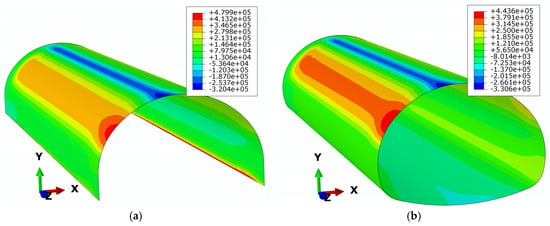
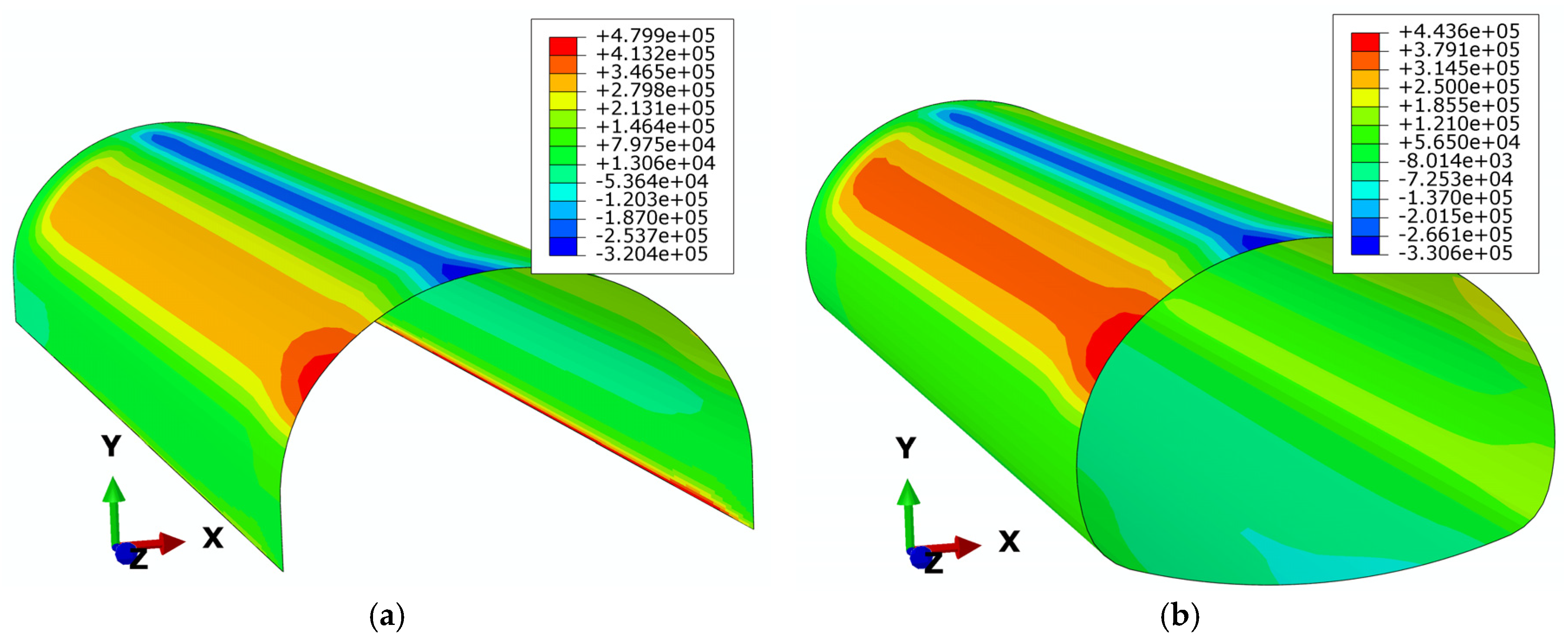
Figure 10 shows the axial force nephograms for the expanded arch foot and invert tunnel models after excavation and support. Owing to the asymmetric CD method excavation, the axial force distributions were asymmetric. Compared to the invert tunnel model, the expanded arch foot lining showed a 1.32% increase in the maximum compressive axial force at the left arch waist, a 5.20% decrease in the maximum tensile axial force at the crown, and a 0.82% increase in the compressive axial force at the sidewall.
Figure 10.
Axial force distribution in secondary lining. (a) Expanded arch foot support scheme; (b) Inverted arch support scheme.
The numerical and physical model results showed qualitatively consistent trends in the redistribution of axial force. Both methods showed that the expanded arch foot lining had a lower axial force at the crown than the conventional invert lining. The reduction was 5.20% in the numerical simulation and 4.38% in the physical model test. In contrast, the axial force at the sidewall increased slightly. The increase was 0.82% in the numerical simulation and 2.90% in the physical model test. The slight differences in magnitude were mainly attributed to the idealized assumptions used in the numerical model and the experimental conditions in the physical model tests. Overall, the numerical results supported the physical model test findings. The expanded arch foot lining showed an axial force distribution comparable to that of the conventional invert lining, with only minor differences in magnitude.
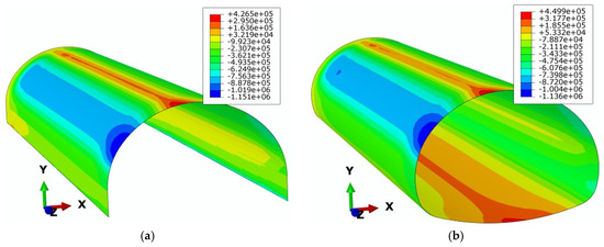
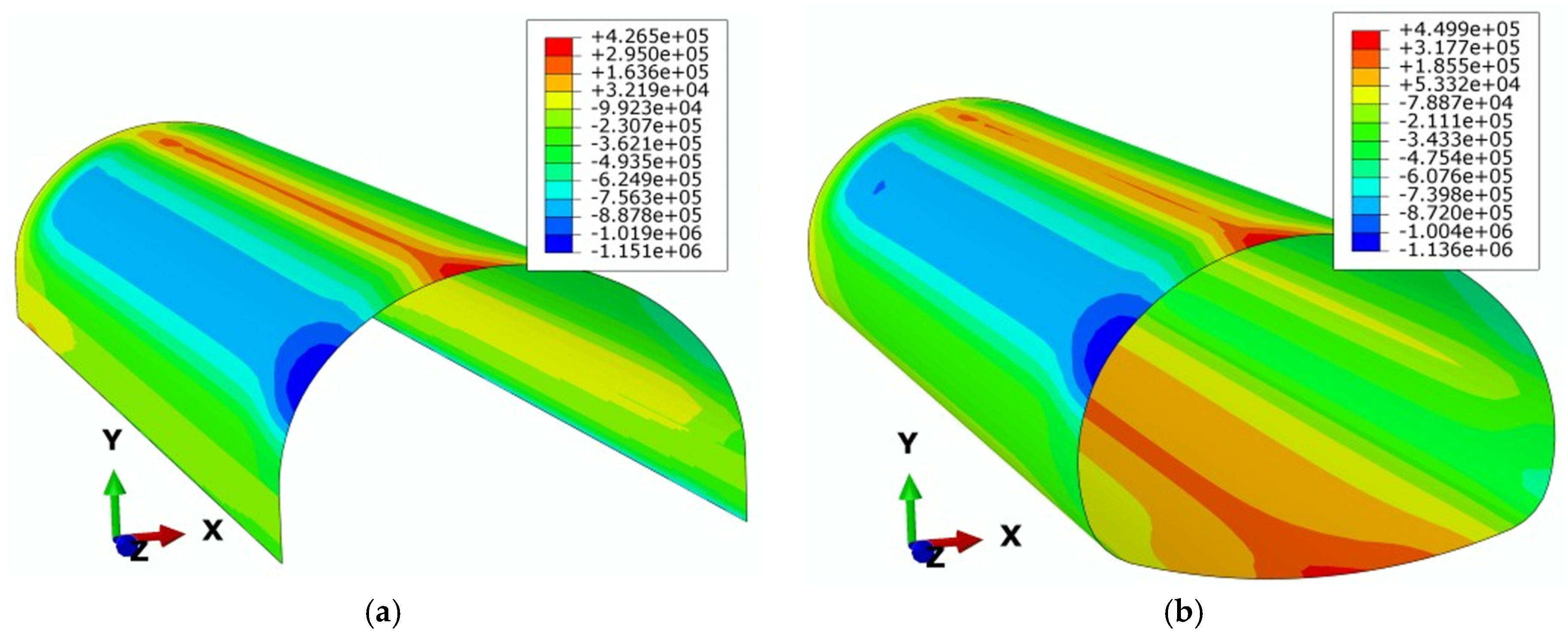
As shown in Figure 11, the bending moments in the lining were also asymmetrically distributed. Compared with the conventional invert lining model, the expanded arch foot lining model showed an 8.18% increase in the maximum positive bending moment at the left arch waist, a 3.20% decrease in the maximum negative bending moment at the crown, and a 77.97% increase in the magnitude of the negative bending moment at the sidewall. The bending-moment results also exhibited qualitative consistency between the two approaches. Both the physical model test and the numerical simulation indicated an increase in bending-moment demand in the sidewall region after omission of the invert, whereas the crown moment changed only slightly and showed the same direction of variation. In the model tests, the expanded arch foot lining exhibited a 40.00% increase in negative moment at the sidewall and a 3.84% decrease in negative moment at the crown. The larger increase at the sidewall in the numerical simulation was mainly caused by the idealized material properties, boundary conditions, and construction process. In contrast, the physical model test involved more variable experimental conditions. Nevertheless, both methods indicated that the expanded arch foot lining produced a bending moment distribution comparable to that of the conventional invert lining. This further supported the feasibility of the proposed support scheme.
Figure 11.
Bending moment distribution in secondary lining. (a) Expanded arch foot support scheme; (b) Inverted arch support scheme.
4.2.2. Analysis of Lining Safety Factor
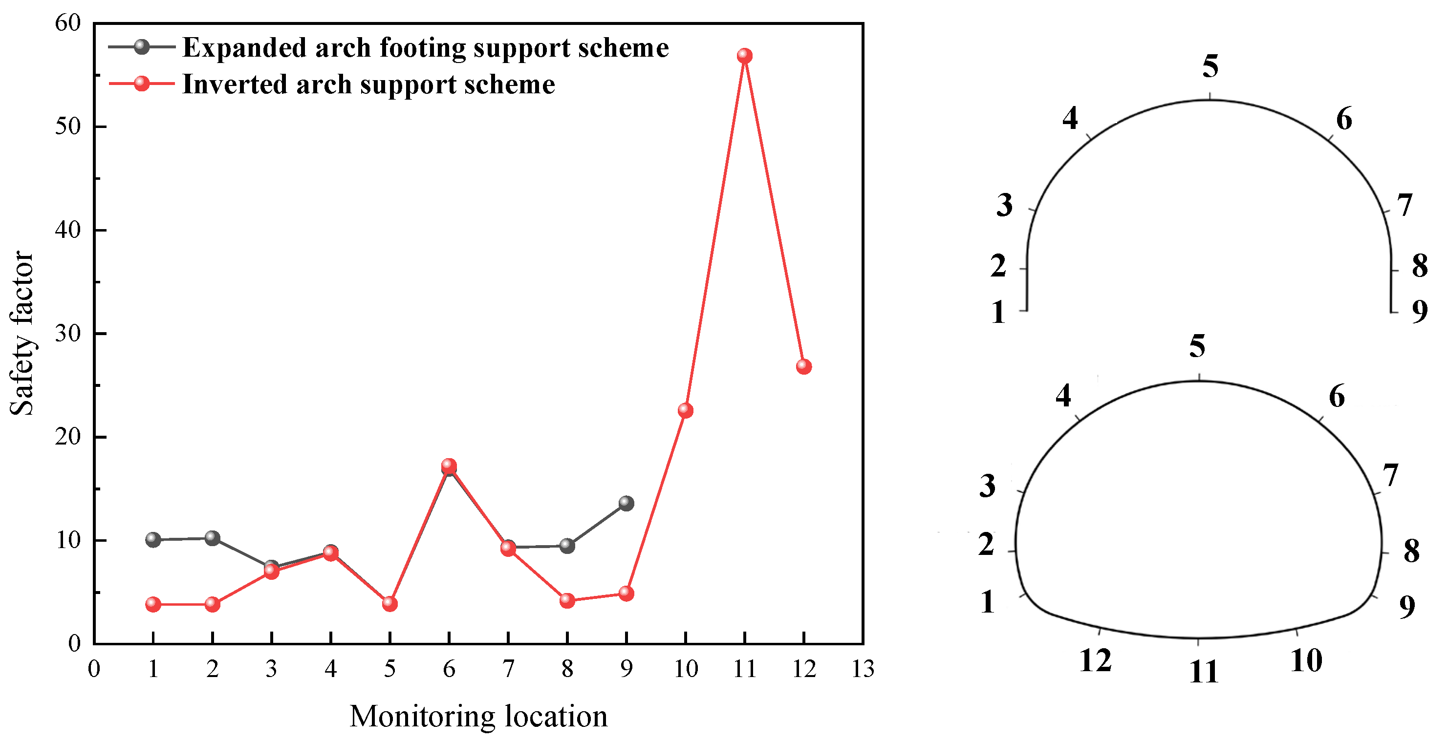
Figure 12 shows the safety factors at the characteristic sections of the lining for the two support schemes after support completion. Due to the asymmetric excavation and support using the CD method, the safety factor distributions were asymmetric. For the expanded arch foot model, the minimum safety factor (3.92) occurred at the crown; for the invert model, the minimum (3.66) occurred at the left arch foot. Notable differences were observed at the arch foot and sidewall. For the invert model, the safety factors at the left arch foot, right arch foot, left sidewall, and right sidewall were 3.66, 4.52, 3.83, and 3.91, respectively. For the expanded arch foot model, the corresponding values were 9.68, 13.54, 9.84, and 9.39, representing increases of 164.48%, 199.56%, 156.92%, and 140.15%, respectively.
Figure 12.
Distribution of lining safety factors. 1-left arch foot, 2-left sidewall, 3-left arch waist, 4-left haunch, 5-crown, 6-right haunch, 7-right arch waist, 8-right sidewall, 9-right arch foot, 10-right arch bottom, 11-arch bottom, and 12-left arch bottom.
Because of the favorable integrity of the tunnel bottom strata in this study, the invert model exhibited significantly higher safety factors at the tunnel bottom. The safety factors at the left, center, and right invert positions reached 22.34, 56.42, and 26.40, respectively. For the expanded arch foot model, the enlarged sections at the arch feet substantially increased the safety factors at the arch foot and sidewall, while safety factors at other locations remained comparable to those of the invert model. All sections in both models satisfied the code requirements. Overall, from the perspective of secondary lining structural safety, the expanded arch foot model was superior to the invert model.
The numerical results further supported the conclusions obtained from the model tests. The expanded arch foot lining had much higher safety factors at the arch foot and sidewall than the conventional invert lining. Meanwhile, the safety factors at the other representative sections remained within an acceptable range. In the model tests, the safety factors at the arch foot and sidewall increased by 89.80% and 36.00%, respectively. In the numerical simulation, the increases were larger, reaching 164.48–199.56% at the arch foot and 140.15–156.92% at the sidewall. Although the magnitudes differed, both methods showed the same trend. When the lower stratum had sufficient strength and integrity, the conventional invert had a relatively large safety reserve and was therefore conservative. By contrast, the expanded arch foot lining improved the safety reserve at the arch foot and sidewall without reducing the safety of the crown or arch waist. This confirmed the rationality of the proposed scheme.
4.2.3. Response of the Lower Hard Stratum
Since the expanded arch-foot scheme relies more directly on the competent stratum beneath the tunnel, the deformation and stress response of the lower rock was further examined using the three-dimensional numerical model. The lower stratum mainly consists of slightly weathered granite and is classified as Class III surrounding rock.
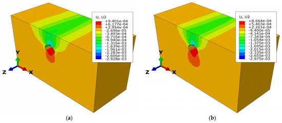
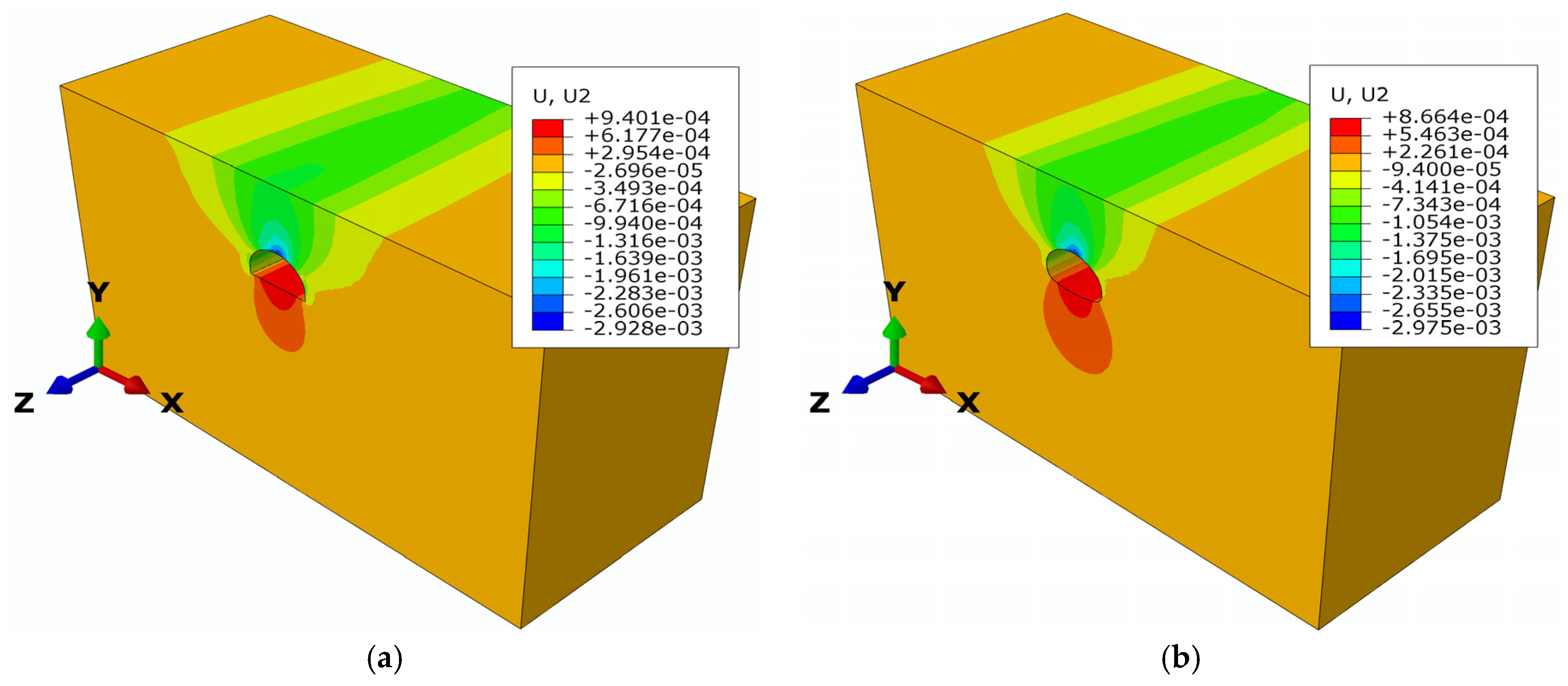
As shown in Figure 13, after excavation and support completion, the surrounding rock exhibited downward displacement above the tunnel and slight upward deformation at the tunnel bottom. For the expanded arch-foot scheme, the maximum upward deformation at the tunnel bottom was 0.940 mm, whereas that of the conventional invert scheme was 0.866 mm. Thus, omission of the invert increased the maximum tunnel-bottom uplift by approximately 8.55%. Nevertheless, the absolute deformation remained small in both cases, indicating that no pronounced deformation of the competent lower stratum occurred under the investigated conditions.
Figure 13.
Vertical displacement of the surrounding rock. (a) Expanded arch foot support scheme; (b) Inverted arch support scheme.
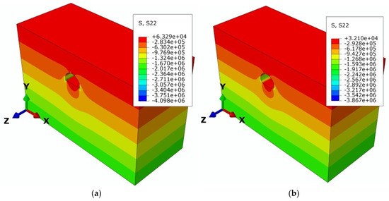
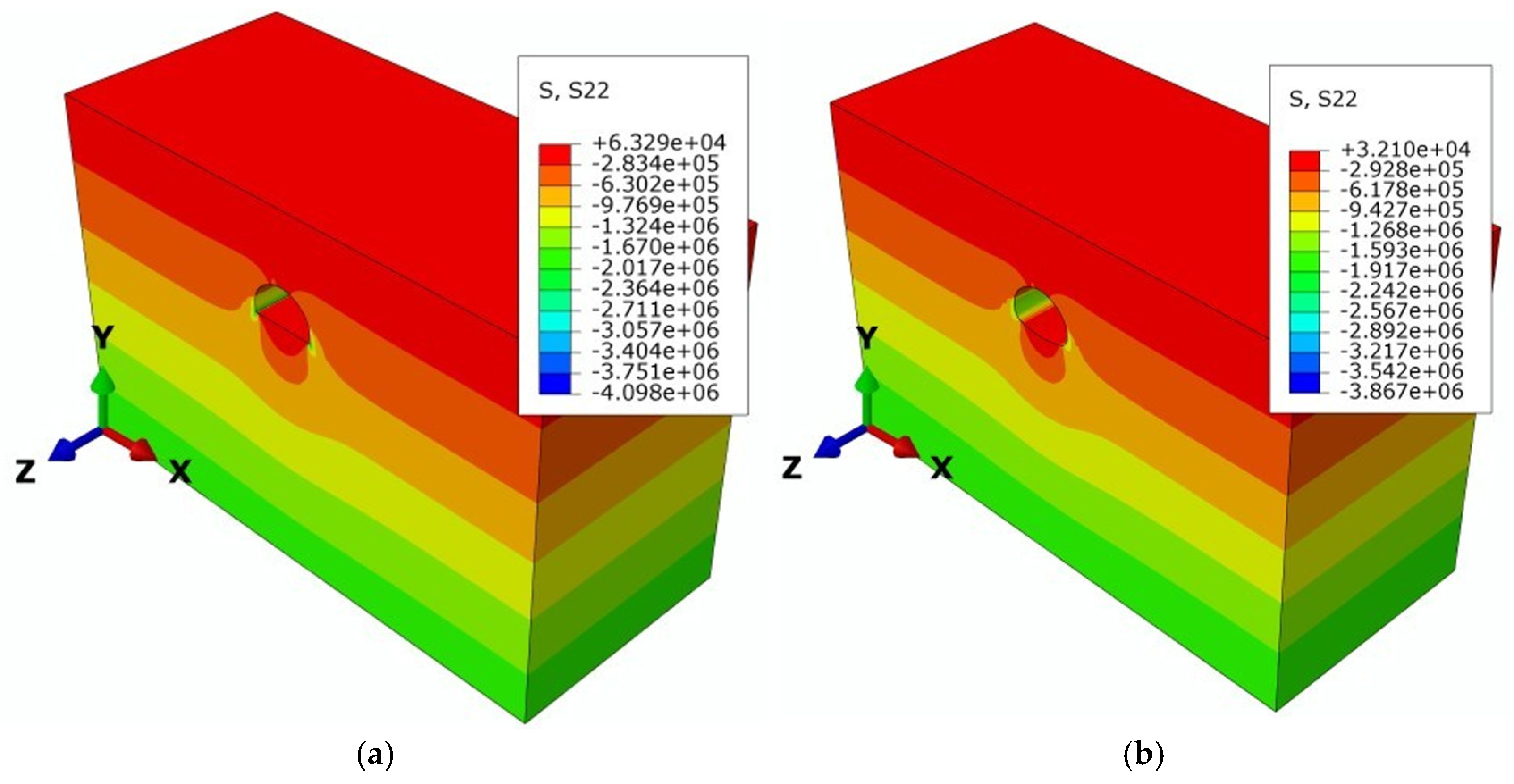
As shown in Figure 14, the vertical stress distributions of the two schemes were generally similar, but a local increase in compressive stress was observed near the arch feet after omission of the invert. The maximum compressive vertical stress in the surrounding rock was 4.098 MPa for the expanded arch-foot scheme and 3.367 MPa for the conventional invert scheme, both occurring near the arch-foot region. This represents an increase of approximately 17.84% for the expanded arch-foot scheme. A small tensile-stress zone also developed near the tunnel bottom, with maximum tensile vertical stresses of 0.0633 MPa and 0.0221 MPa for the expanded arch-foot and conventional invert schemes, respectively. These results indicate that replacing the invert with enlarged arch feet changes the load-transfer path and concentrates a larger proportion of the structural reaction in the arch-foot region and the underlying hard stratum.
Figure 14.
Rock stress distribution. (a) Expanded arch foot support scheme; (b) Inverted arch support scheme.
The physical model test provides complementary evidence for this load-transfer mechanism. The measured lining–rock contact pressure at the left arch foot was approximately 186.35 kPa for the expanded arch-foot scheme, compared with 170.52 kPa for the conventional invert scheme. The increased contact pressure is consistent with the numerical stress redistribution and indicates that a greater proportion of the load is transferred through the enlarged arch foot.
5. Discussion
This study investigated the feasibility of replacing the conventional invert lining with an expanded arch foot lining in a highway tunnel constructed in upper soft and lower hard composite ground. Physical model tests and numerical simulations were conducted to compare the internal forces, safety factors, and contact pressure between the lining and surrounding rock. However, several limitations should be noted.
Firstly, the physical model tests have limitations in terms of experimental setup, replication, and uncertainty. Although preliminary trial tests were conducted before the formal experiments to verify the loading procedure, sensor connections, and data acquisition system, these tests were used only for experimental preparation and were not included in the quantitative analysis. For the formal experiments, one independently fabricated model and one complete loading test were conducted for each support scheme. In addition, only vertical stress was reproduced through uniform airbag loading, whereas horizontal in situ stress and the lateral pressure coefficient were not explicitly simulated because of limitations of the loading system. Therefore, test-to-test repeatability, specimen variability, rigorous uncertainty propagation, and the influence of the complete three-dimensional stress state could not be fully quantified. Accordingly, differences of only a few percent between the two physical model tests are not interpreted as quantitatively significant; instead, the experimental results are mainly used to compare the overall response patterns of the two schemes under the same simplified boundary conditions and are interpreted together with the numerical simulation results. Future studies should include repeated independently fabricated models, quantitative uncertainty analysis, and combined vertical and horizontal loading to improve the reliability and representativeness of the physical tests.
Secondly, although the results of this study demonstrate that the expanded arch-foot lining can replace the conventional invert lining under the investigated conditions, its applicability should be limited to projects with comparable geological, geometrical, hydraulic, and loading conditions. A continuous and competent lower stratum should exist beneath the arch-foot region and provide sufficient bearing resistance to support the transferred loads. In the present project, the principal lower bearing stratum was Class III surrounding rock with an elastic modulus of 8.5 GPa, cohesion of 0.75 MPa, and friction angle of 42°; these values describe the investigated case and should not be interpreted as universal threshold criteria. The degree of arch-foot enlargement should be determined according to the tunnel span, lining thickness, position of the soft–hard rock interface, lower-stratum bearing resistance and deformation characteristics, and construction conditions. In addition, groundwater pressure, significant tectonic stress, and seismic loading were not considered in the present analyses. Therefore, omission of the invert should only be considered after project-specific assessment of the geological conditions, tunnel geometry, groundwater environment, bearing resistance, and loading conditions. Additional numerical analysis, model testing, or field monitoring should be conducted before applying the proposed scheme to conditions substantially different from those investigated in this study.
Thirdly, this study mainly evaluated the feasibility of replacing the conventional invert lining with an expanded arch foot lining from the perspectives of internal force, safety factor, and contact pressure under the investigated engineering conditions. The long-term performance of the expanded arch foot lining after eliminating the closed invert system was not fully addressed. This issue is especially important under conditions involving potential floor heave, seasonal groundwater variation, or seismic action in the weak upper stratum. Further investigation through long-term field monitoring, refined numerical analysis, and additional model tests is therefore required.
Finally, the present study did not directly measure the settlement of the expanded arch feet or the bearing-pressure distribution beneath their bases. Although the numerical results showed only small deformation of the lower Class III stratum and a stable redistribution of compressive stress toward the arch-foot region, these observations should not be regarded as a complete verification of the ultimate bearing capacity of the underlying rock. A rigorous assessment would require direct base-contact measurements and evaluation of the local stress state or plastic response against an appropriate rock-mass resistance criterion. Therefore, the conclusions of the present study are restricted to the comparative response of the two support schemes under the investigated geological and loading conditions. Future work should include arch-foot settlement monitoring, contact-pressure measurements beneath the expanded feet, plastic-zone or yield-state evaluation of the lower rock, and field monitoring to establish the long-term bearing performance of the proposed system.
6. Conclusions
This study evaluated the feasibility of replacing the conventional invert lining with an expanded arch foot lining in upper soft and lower hard composite ground. The main conclusions are as follows:
- (1)
- From the perspective of internal force, the expanded arch foot lining showed a mechanical response generally comparable to that of the conventional invert lining. After the invert was omitted, the internal force distribution was redistributed to some extent. In the model tests, the axial forces at the arch foot and sidewall increased by 36.20% and 2.90%, respectively, and the bending moments increased by 33.33% and 40.00%, respectively. In contrast, the axial force and bending moment at the crown decreased by 4.38% and 3.84%, respectively. The numerical simulations showed the same overall trend. These results indicate that the expanded arch foot changed the load transfer pattern but did not cause a significant deterioration in the overall force state of the lining.
- (2)
- From the perspective of structural safety, the expanded arch foot lining provided sufficient safety reserves and showed higher safety factors at several key sections. In the model tests, the safety factors at the arch foot and sidewall increased by 89.80% and 36.00%, respectively. In the numerical simulations, the safety factors at the arch foot and sidewall increased by 140.15% to 199.56%. At the crown, arch waist, and haunch, the safety factors of the two lining schemes were close, and all examined sections satisfied the code requirements. These results indicate that the expanded arch foot lining met the structural safety requirements without relying on a conventional invert.
- (3)
- From the perspective of contact pressure between the lining and surrounding rock, the two lining schemes showed different pressure transfer characteristics. The expanded arch-foot scheme changed the load-transfer mechanism at the lower part of the tunnel. The three-dimensional numerical results showed that the maximum tunnel-bottom uplift was 0.940 mm for the expanded arch-foot scheme and 0.866 mm for the conventional invert scheme, while the maximum compressive vertical stress near the arch-foot region increased from 3.367 MPa to 4.098 MPa. The physical model test also showed a higher arch-foot lining–rock contact pressure for the expanded arch-foot scheme. These results indicate that a larger proportion of the load was transferred through the enlarged arch feet into the lower hard stratum. Despite this redistribution, deformation of the lower stratum remained small under the investigated conditions.
Overall, the physical model tests and numerical simulations show that the expanded arch-foot lining provides a structural response comparable to that of the conventional invert lining under the geological and loading conditions investigated in this study. The lower hard stratum exhibited limited deformation despite the increased stress transferred through the arch-foot region. Therefore, the expanded arch-foot scheme may be considered a feasible alternative to the conventional invert for tunnels with similar upper-soft and lower-hard ground conditions. However, the present results should be interpreted as a comparative verification under the modelled conditions rather than as a general verification of the ultimate bearing capacity of the lower rock. Further field monitoring and direct assessment of arch-foot settlement, base contact pressure, and lower-rock yielding are required before broader application.
Author Contributions
Conceptualization, C.Z., X.S. and J.L.; Methodology, C.Z. and S.Z.; Software, S.G.; Validation, L.L.; Investigation, C.Z.; Resources, S.Z.; Writing—original draft, L.L. and S.G.; Writing—review & editing, C.Z.; Project administration, S.Z.; Funding acquisition, S.Z. All authors have read and agreed to the published version of the manuscript.
Funding
The authors gratefully acknowledge the support of the Shandong Provincial Natural Science Foundation (Grant no.ZR2025MS727, ZR2024QE001), and Shandong Province Youth Innovation and Technology Program for Higher Education Institutions (Grant no. 2024KJH040).
Institutional Review Board Statement
Not applicable.
Informed Consent Statement
Not applicable.
Data Availability Statement
The data presented in this study are available in the article.
Conflicts of Interest
Author Changan Zhang, Xing Shao, and Jialu Li are employed by the company Shandong Provincial Communications Planning and Design Institute Group Co., Ltd. The remaining authors declare that the research was conducted in the absence of any commercial or financial relationships that could be construed as potential conflicts of interest.
References
- Zhou, Y.; Lai, H.P.; Liu, Y.Y.; Hong, Q.Y.; Li, Z.L. Analysis and treatments of primary support failure in large-span tunnel under a soft-hard interbedded surrounding rock mass. Eng. Fail. Anal. 2024, 156, 107755. [Google Scholar] [CrossRef] [Scilit]
- Huang, M.S.; Li, Y.S.; Shi, Z.H.; Lü, X.L. Face stability analysis of shallow shield tunneling in layered ground under seepage flow. Tunn. Undergr. Space Technol. 2022, 119, 104201. [Google Scholar] [CrossRef] [Scilit]
- Ma, S.K.; Duan, Z.B.; Huang, Z.; Liu, Y.; Shao, Y. Study on the stability of shield tunnel face in clay and clay-gravel stratum through large-scale physical model tests with transparent soil. Tunn. Undergr. Space Technol. 2022, 119, 104199. [Google Scholar] [CrossRef] [Scilit]
- Yang, S.Q.; Chen, M.; Fang, G.; Wang, Y.C.; Meng, B.; Li, Y.H.; Jing, H.W. Physical experiment and numerical modelling of tunnel excavation in slanted upper-soft and lower-hard strata. Tunn. Undergr. Space Technol. 2018, 82, 248–264. [Google Scholar] [CrossRef] [Scilit]
- Yang, S.Q.; Tao, Y.; Xu, P.; Chen, M. Large-scale model experiment and numerical simulation on convergence deformation of tunnel excavating in composite strata. Tunn. Undergr. Space Technol. 2019, 94, 103133. [Google Scholar] [CrossRef] [Scilit]
- Wu, X.; Xu, J.; Wang, S.; Sha, P.; Han, Z.; Chen, X.; Shu, S.; Qiao, W.; Zeng, X. Ground deformation of shield tunneling through composite strata in coastal areas. Buildings 2024, 14, 1236. [Google Scholar] [CrossRef] [Scilit]
- Cui, X.; Li, P.; Chen, Y.; Jia, F.; Ge, Z.; Li, S. Analysis of face stability for a shield tunnel in the inclined strata with soft upper and hard lower layers. Alex. Eng. J. 2025, 125, 677–691. [Google Scholar] [CrossRef] [Scilit]
- Huang, F.; Liu, X.; Wu, C.; Tang, W.; Zheng, A. Stress redistribution in some supported subway station tunnels within upper-soft and lower-hard strata during Excavation: A physical model study. Tunn. Undergr. Space Technol. 2025, 159, 106466. [Google Scholar] [CrossRef] [Scilit]
- Feng, J.; Tan, Y.; Ma, K.; Zhang, J.; Pan, T.; Yao, S.; Song, J.; Li, Z. Stability classification and construction method analysis of subway stations in upper-soft and lower-hard strata. Eng. Fail. Anal. 2023, 153, 107550. [Google Scholar] [CrossRef] [Scilit]
- Liang, J.; Xu, A.; Ba, Z.; Wu, Z.; Yan, Q.; Zhu, Y. Seismic response of ultra-large diameter shield tunnel in upper-soft and lower-hard site: Shaking table tests and numerical simulations. Soil Dyn. Earthq. Eng. 2023, 164, 107634. [Google Scholar] [CrossRef] [Scilit]
- Li, L.y.; Du, X.l.; Zhou, J. Numerical simulation of site deformation induced by shield tunneling in typical upper-soft-lower-hard soil-rock composite stratum site of Changchun. KSCE J. Civ. Eng. 2020, 24, 3156–3168. [Google Scholar] [CrossRef] [Scilit]
- Li, X.; Di, H.g.; Zhou, S.x.; Huo, P.; Huang, Q. Effective method for adjusting the uplifting of shield machine tunneling in upper-soft lower-hard strata. Tunn. Undergr. Space Technol. 2021, 115, 104040. [Google Scholar] [CrossRef] [Scilit]
- Guo, X.p.; Jiang, A.n. Study on applicability of double layer superimposed primary support arch cover method for large-span station in upper soft and lower hard stratum. KSCE J. Civ. Eng. 2022, 26, 1407–1418. [Google Scholar] [CrossRef] [Scilit]
- Liu, C.; Zhang, S.l.; Zhang, D.l.; Zhang, K.p.; Wang, Z.z. Model tests on progressive collapse mechanism of a shallow subway tunnel in soft upper and hard lower composite strata. Tunn. Undergr. Space Technol. 2023, 131, 104824. [Google Scholar] [CrossRef] [Scilit]
- Luo, Z.m.; Zhang, Y.j.; Chen, J.h.; Ou, X.f.; Zhang, X.y. Stress and deformation response of pipe jacking in upper-soft and lower-hard strata: A case study in Changsha. Eng. Fail. Anal. 2024, 166, 108879. [Google Scholar] [CrossRef] [Scilit]
- Cui, J.b.; Xie, L.f.; Qin, Y.j.; Liu, X.j.; Qian, J.g. Study on Blasting Characteristics of Shallow and Deep Soft-hard Rock Strata Based on Energy Field. KSCE J. Civ. Eng. 2023, 27, 1942–1954. [Google Scholar] [CrossRef] [Scilit]
- Zhang, X.; Song, Q.; Yao, Z.; Su, D.; Zhang, Y.; Li, Q. Limit Equilibrium Models for Tunnel Face Stability in Composite Soft-Hard Strata. Appl. Sci. 2023, 13, 10748. [Google Scholar] [CrossRef] [Scilit]
- Zhang, S.; Gao, J.; Liu, C.; Li, P.; Yang, Z.; Lu, X. Model test on the collapse mechanism of subway tunnels in the soil-sand-rock composite strata. Eng. Fail. Anal. 2024, 162, 108356. [Google Scholar] [CrossRef] [Scilit]
- Zhan, T.; Hu, Z.; Kuang, Y.; Zhu, Z.; Liao, K. Tunnel face stability in strata rich in water with soft upper and hard lower layers. Sci. Rep. 2025, 15, 4795. [Google Scholar] [CrossRef] [Scilit]
- Yuan, G.; Xu, J.f.; Li, S.r.; Shi, Z.; Yan, S.m. Optimization on Highway Tunnel Construction in Upper-hard Lower-weak Stratum with Intensely Weathered Granitic Migmatite. J. Highw. Transp. Res. Dev. 2024, 41, 153–162. [Google Scholar]
- Wang, M.n.; Wong, H.m.; Li, Z.y. Study on the Mechanic Behaviour of Tunnel Invert. Chin. J. Geotech. Eng. 1996, 18, 46–53. [Google Scholar]
- Li, L.y.; Yang, J.s.; Wu, J.; Wang, S.y.; Fang, X.h.; Zhang, C. Failure mechanism and countermeasures of an operational railway tunnel invert in horizontally stratified rock masses. Int. J. Geomech. 2022, 22, 04021280. [Google Scholar] [CrossRef] [Scilit]
- Du, M.q.; Su, J.; Wang, X.c.; Lu, Z.l. Field test and numerical analysis of dynamic stress of high-speed railway tunnel invert in mudstone. Geotech. Geol. Eng. 2021, 39, 829–837. [Google Scholar] [CrossRef] [Scilit]
- Wang, J.; Liang, H.; Tang, M.; Zhang, J.; He, J.; He, H.; Wang, J.; Tian, X.; Huang, R. Field and Numerical Study of Tunnel Invert Deformation in Gently Dipping Rock Layers. Geotech. Geol. Eng. 2026, 44, 6. [Google Scholar] [CrossRef] [Scilit]
- Zhang, T.; Shi, Y.f.; Wang, S.y.; Hu, M.h.; He, S.j. Investigation of acting load and mechanical characteristics of shield tunnel lining in upper-soft and lower-hard stratum. Soils Found. 2025, 65, 101647. [Google Scholar] [CrossRef] [Scilit]
- Chen, Y.z. Research on Structural Mechanics Characteristics and Rapid Construction Techniques for Inverted Arch Lining Structures in High-Speed Railway Tunnels. Master’s Thesis, China Academy of Railway Sciences, Beijing, China, 2012. [Google Scholar]
- Ma, W.B.; Chai, J.F.; Han, Z.L.; Ma, Z.G.; Guo, X.X.; Zou, W.H.; An, Z.L.; Li, T.F.; Niu, Y.B. Research on Design Parameters and Fatigue Life of Tunnel Bottom Structure of Single-Track Ballasted Heavy-Haul Railway Tunnel with 40-Ton Axle Load. Math. Probl. Eng. 2020, 2020, 3181480. [Google Scholar] [CrossRef] [Scilit]
- Xu, D.q.; Liu, J.; Sun, Y. Research and Design Optimization of Canceling Setting Invert in Road Tunnel. Adv. Mater. Res. 2012, 594, 1201–1205. [Google Scholar] [CrossRef] [Scilit]
- Chen, P.; Liao, J.; Yin, M.l.; Sun, Z.y. Feasibility Study on Tunneling in Soft Roof and Hard Base Rock without Inverted Arch. J. Munic. Technol. 2015, 33, 104–107. [Google Scholar]
- Zhang, H.; Zhang, T.; Shi, Y.; Lai, S.; Liu, W. Tunnel Cross-section Optimization Design in Upper-soft Lower-hard Composite Strata Based on Lining Structure Minimum Bending Moment. Urban Mass Transit 2024, 27, 8. [Google Scholar] [CrossRef]
- Fu, H.; Xu, W.; Wu, Y. Research on the influence of tunnel invert excavation on the rheological deformation of different levels of surrounding rock. Appl. Sci. 2023, 13, 6960. [Google Scholar] [CrossRef] [Scilit]
- Feng, J.; Gong, L.; Wang, L.; Zhou, P.; Zhang, P.; Li, Y.; Liu, Z. Study on failure mechanism and treatment measures of floor heave of high-speed railway tunnel in the interbedded surrounding rock with high geostress. Eng. Fail. Anal. 2023, 150, 107365. [Google Scholar] [CrossRef] [Scilit]
- Du, M.; Liu, X.; Wang, Y.; Huang, H.; Zhu, Z.; Zhang, Y.; Wang, X. Crack propagation mechanism of inverted arches in large cross-section tunnels. Eng. Fail. Anal. 2023, 152, 107514. [Google Scholar] [CrossRef] [Scilit]
- Luo, P.; Li, D.; Zhang, C.; Ru, W.; Han, Z.; Ma, J. Experimental investigation on biaxial mechanical properties of laminated rock and floor heave mechanism of tunnel based on DIC. Eng. Fail. Anal. 2024, 156, 107848. [Google Scholar] [CrossRef] [Scilit]
- Xu, Z.; Wang, H.; Tian, H.; Xu, Y.; Yu, J.; Zhang, C. Deformation control method for inverted arch in railway tunnels. J. Mt. Sci. 2025, 22, 2211–2226. [Google Scholar] [CrossRef] [Scilit]
- Fan, S.; Jia, W.; Xie, J.; Feng, Z.; Tian, S.; Li, S. Study on the disaster mechanism and treatment measures of invert uplift cracking of in-service tunnel—A case research. Constr. Build. Mater. 2025, 471, 140772. [Google Scholar] [CrossRef] [Scilit]
- Li, C.; Wu, Y. Analysis and control of the causes of the uplift of the invert of deep tunnels. Discov. Appl. Sci. 2024, 7, 11. [Google Scholar] [CrossRef] [Scilit]
- Zhang, K.p. Progressive Damage Pattern and Evolution of Soil-Rock Composite Strata Under the Influence of Subway Tunnel Construction. Master’s Thesis, Qingdao University of Technology, Qingtao, China, 2021. [Google Scholar]
- Wang, F.y.; Yuan, J.k.; Yang, C.l. Experimental Study on the Mixture Ratio of Similar Materials in Soft Rocks in Tunnel Model Test. J. Anhui Jianzhu Univ. 2020, 28, 8–13. [Google Scholar]
- Lei, Z.d.; Yan, Z.g. Experimental Study on Proportioning of Similar Materials for Surrounding Rock of Class III. Chin. J. Undergr. Space Eng. 2022, 18, 832–839+848. [Google Scholar] [CrossRef]
- Li, S.; Zhang, B.; Wang, H.; Wang, W.; Xu, F.; Li, Q. A large-scale model test system for stability study of tunnel under static-dynamic load. Geotech. Geol. Eng. 2022, 40, 575–585. [Google Scholar] [CrossRef] [Scilit]
- Niu, H.; Weng, X.; Tian, C.; Wang, D. Model test and back analysis of shield tunnel load distribution in soft clay. Adv. Mater. Sci. Eng. 2021, 2021, 9992348. [Google Scholar] [CrossRef] [Scilit]
- JTG 3370.1—2018; Specifications for Design of Highway Tunnels Section 1 Civil Engineering. Ministry of Transport of the People’s Republic of China: Beijing, China, 2018.
- Zeng, C. Analysis of Ground Surface Settlement Patterns in Cavity-Containing Strata Under Tunnel Construction Disturbance. Struct. Eng. 2025, 41, 193–203. [Google Scholar] [CrossRef]
- Jia, J.; Tenorio, V.O.; Zhang, B.; Li, M.; Xin, C. Stability and reliability of a shallow tunnel in soft surrounding rock: Construction technology and prediction. Arab. J. Geosci. 2022, 15, 289. [Google Scholar] [CrossRef] [Scilit]
- Serhal, R.; Peña-Olarte, A.A.; Miraei, M.; Schorr, J.; Wiegel, A. Deterministic versus random finite element analysis of tunnel response: A case study in munich area. Geotech. Geol. Eng. 2026, 44, 14. [Google Scholar] [CrossRef] [Scilit]

Disclaimer/Publisher’s Note: The statements, opinions and data contained in all publications are solely those of the individual author(s) and contributor(s) and not of MDPI and/or the editor(s). MDPI and/or the editor(s) disclaim responsibility for any injury to people or property resulting from any ideas, methods, instructions or products referred to in the content. |
© 2026 by the authors. Licensee MDPI, Basel, Switzerland. This article is an open access article distributed under the terms and conditions of the Creative Commons Attribution (CC BY) license.