


Abstract
The rotational error motion of precision aerostatic rotary stages substantially affects the accuracy of machining and measuring equipment. A comprehensive and flexible error modeling method is absent. This paper develops an analytical model for the error motion of an aerostatic rotary stage bearing, utilizing linear superposition and spatial force equilibrium principles. The error motion of an orifice-restricted rotary stage is computed using this approach. The impact of bearing manufacturing inaccuracies (e.g., journal roundness, thrust plate profile) and micro-vibrations caused by internal turbulence is analyzed. Finally, the model was validated experimentally using the reversal method. The results indicate that bearing manufacturing errors positively correlate with error motion, and micro-vibration considerably influences errors at the sub-100 nm level. The relative error between the predicted and measured values is less than 15%, confirming the validity and applicability of this modeling and analytical approach. This research enhances error motion analysis methods and offers a novel constructive reference for predicting and optimizing error motion in precision aerostatic rotary stages.
1. Introduction
Aerostatic bearings exhibit advantages, including exceptional precision, low friction, and high reliability. Precision aerostatic rotary stages that integrate these bearings as fundamental components are extensively utilized in the semiconductor industry and the field of precise measurement. The rotational error motion of its axis can significantly affect the machining and measuring accuracy of products. Consequently, the modeling and analysis of error motion in these stages facilitate the comprehension and prediction of how structural and operational parameters affect error characteristics, thereby enabling iterative parameter optimization to improve rotational precision.
Scholars have extensively undertaken research on models for analyzing error motion in bearings. Fundamentally, establishing error motion models relates to methods for solving air film bearing forces. Linearization methods utilizing small perturbation theory can facilitate the analysis of error motion by approximating the air film as elastic elements with equivalent stiffness, thereby converting the force system within the orifice-restricted air film domain into a spatially arbitrary force system. Multiple studies focus on the influence of journal roundness inaccuracies on radial error motion [1,2,3]. Sun partitioned air cavities into equivalent narrow slits that correspond to the number of orifices, revealing that radial error motion is governed by radial force equilibrium conditions [4]. Akira et al. experimentally established that the frequency components of spindle roundness errors, especially odd-order harmonics, significantly degrade rotational accuracy [5]. Hwang et al. proposed an estimation approach that integrates external loads as input variables to minimize spindle error motion [6]. Additional research has simultaneously analyzed the effects of roundness errors and rotational speeds on bearing error motion [7].
Researchers typically develop dynamic models of bearing–rotor systems to simulate spindle rotational trajectories. These models convert the lubrication and support functions of bearings into multi-degree-of-freedom spring-damper systems. Error motion analysis is conducted by computing the dynamic stiffness and damping coefficients of bearings [8,9,10]. Meng developed a spindle center trajectory computing method based on flow continuity principles, investigating the impact of shape errors on trajectory patterns [11]. Meruans et al. conducted a comparative analysis of stiffness and damping variations in finite-length bearings utilizing CFD simulations, and subsequently computed hydrostatic spindle error trajectories [12]. Fundamentally, the spindle’s rotational trajectory constitutes a characterization of radial error motion.
In theoretical research, Cappa et al. proposed a steady-state model for analyzing rotational accuracy in aerostatic journal bearings, demonstrating that an increase in orifice quantity diminishes radial error motion [13]. Kim’s team employed the Newton–Raphson algorithm alongside point source theory to solve dynamic Reynolds equations, revealing that roundness error harmonics, especially bimodal and trimodal defects, critically degrade spindle accuracy, and advising their reduction during manufacturing [14]. Wang et al. established a finite difference model utilizing Reynolds equations, investigating the impacts of rotor eccentricity and equilibrium location on rotational precision [15]. Cui et al. developed an innovative hybrid model based on CFD and DMT to investigate the impacts of surface waviness and irregularities on rotational accuracy [16].
Recent studies have further advanced error motion analysis from the perspective of multi-component error coupling. Zhang et al. extended the Reynolds equation to incorporate shaft shape errors and fluid inertia effects, quantifying their combined impact on radial error motion, yet their analysis was limited to radial degrees of freedom [17]. Shi et al. revealed that surface waviness harmonics and angular misalignment would jointly distort the air film pressure distribution, but their work focused on static bearing performance rather than full-axis error motion [18]. For five-degree-of-freedom (5-DOF) bearing–rotor systems, Jia et al. established a dynamic model for transient response calculations, while manufacturing form errors of thrust plates and journals were not fully integrated into their error prediction framework [19].
In summary, current models of bearing error motion primarily analyze radial error, rarely addressing axial and tilt errors, resulting in inadequate analysis. Crucially, for applications requiring sub-100 nm precision (e.g., semiconductor metrology), micro-vibrations caused by internal turbulence significantly impact accuracy. Despite multiple studies confirming this correlation [20,21,22,23], quantitative evaluations remain scarce. Though Yabe et al. conducted preliminary investigations into axial error [24], tilt error [25], and micro-vibration effects [26], their analytical approaches are constrained to particular bearing configurations with set orifice counts, resulting in limited model generalizability. Consequently, developing a comprehensive and adaptable error motion modeling methodology is essential.
This study focuses on establishing a comprehensive error motion model for precision aerostatic rotary stages, integrating bearing manufacturing inaccuracies and micro-vibration influences. The model facilitates comprehensive prediction of all error motion components, providing foundational insights for parametric optimization during the design phase to reduce the error motion of the rotary stage.
2. Modeling for Error Motion
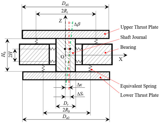
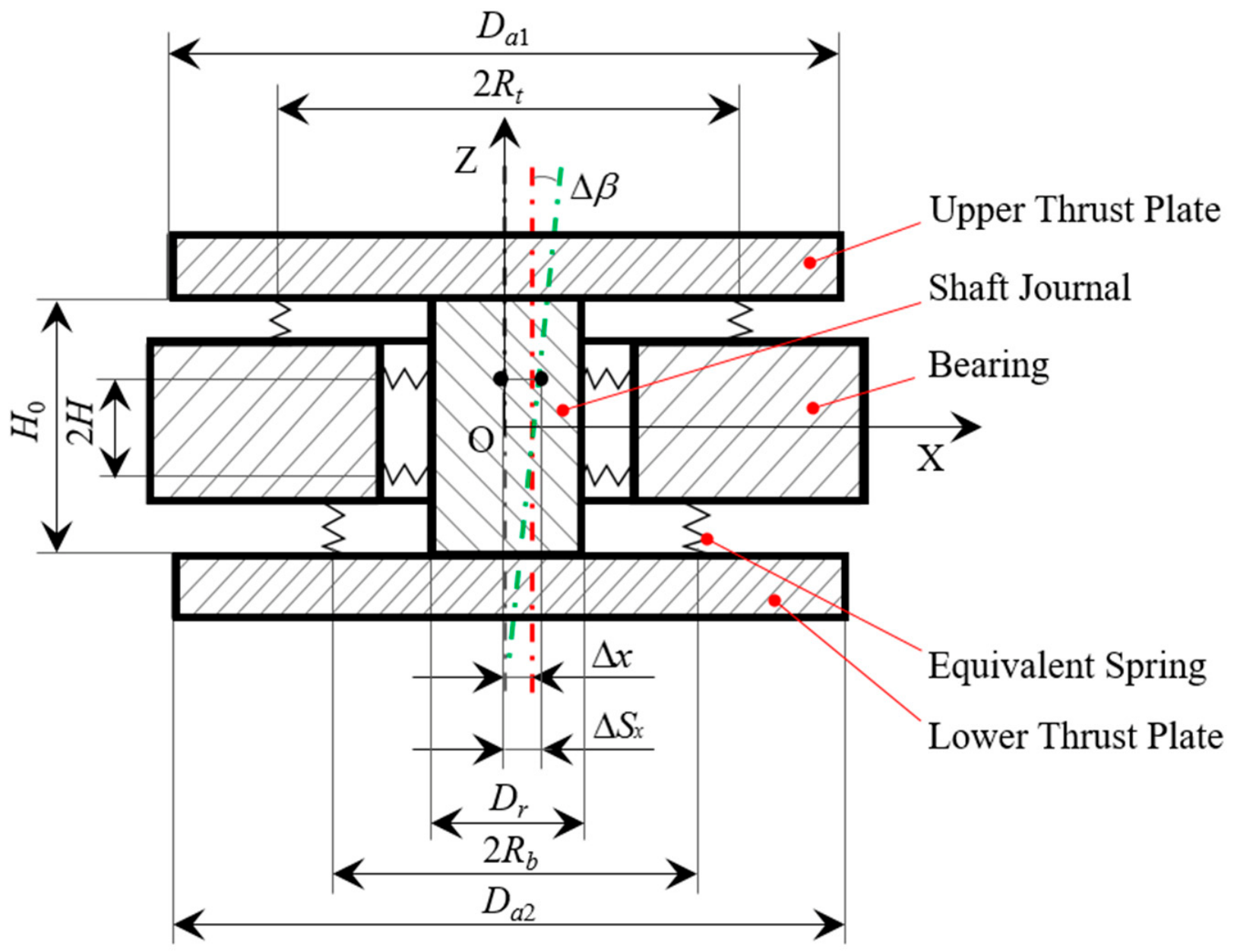
This section develops an error motion model for aerostatic rotary stages via spatial force equilibrium. The primary assumptions include rigid-body motion of the journal and thrust plates, with the amplitude of error motion being insignificant relative to the average air film thickness, hence justifying the application of the linear superposition principle. The support mechanisms of thrust and journal bearing orifices are modeled as compressed springs, with the fundamental assumption that equivalent spring stiffness remains equal throughout all orifices within upper thrust bearing, lower thrust bearing, and journal bearing regions, respectively. The stiffness discussed in this model refers to the support stiffness of the aerostatic bearing system, which is generated by the reactive pressure of the compressed air film, rather than an intrinsic material property of air. The equivalent mechanical model of an aerostatic bearing is illustrated in Figure 1.
Figure 1.
The equivalent mechanical model of aerostatic bearing.
The diagram illustrates a longitudinal section (XOZ plane) of an aerostatic bearing bisected along its axis. Here, H signifies half the axial spacing between radial orifices, Rt/Rb denotes the radii of the distribution circles for the upper and lower thrust orifices, Da1/Da2 represent the diameters of the upper and lower thrust plates, and Dr/H0 correspond to the journal diameter and height. Fundamentally, the model assumes that the center of tilting motion coincides with the geometric center of the bearing (origin O).
2.1. Analysis of Air Film Thickness Variation
This study focuses on the influence of bearing manufacturing inaccuracies (thrust plate form discrepancies, journal roundness deviations) and turbulence-induced micro-vibrations on error motion in precision aerostatic rotary stages. To determine the causal relationship between these primary error sources and error motion, we initially examine variations in air film thickness in thrust and journal bearings under error excitation.
The five components of error motion are represented as Δx, Δy, Δz, Δα, and Δβ, signifying: radial error motion along the X-axis, radial error motion along the Y-axis, axial error motion along the Z-axis, tilt error motion about the X-axis, and tilt error motion about the Y-axis; the variation in air film thickness at any orifice of the upper and lower thrust bearings can be expressed as the following functions:
where subscript z refers to the axial direction, while t and b denote the upper and lower thrust plates, respectively. θ1 indicates the angular position of axial orifices in relation to the X-axis in the XOY plane; Δa represents axial error sources, with subscripts p and v distinguishing between thrust plate form errors and micro-vibration sources, and i signifies the ordinal number of axial orifices.
As depicted in Figure 1 within the XOZ plane, during error motion, the X-directional displacement of radial orifices on the upper and lower journal sides arises from the combined effects of radial error Δx and tilt error Δβ, expressed as follows:
Similarly, the Y-direction displacements at radial orifices on the upper and lower journal sides can be expressed as follows:
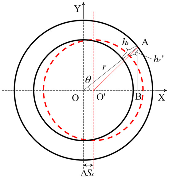
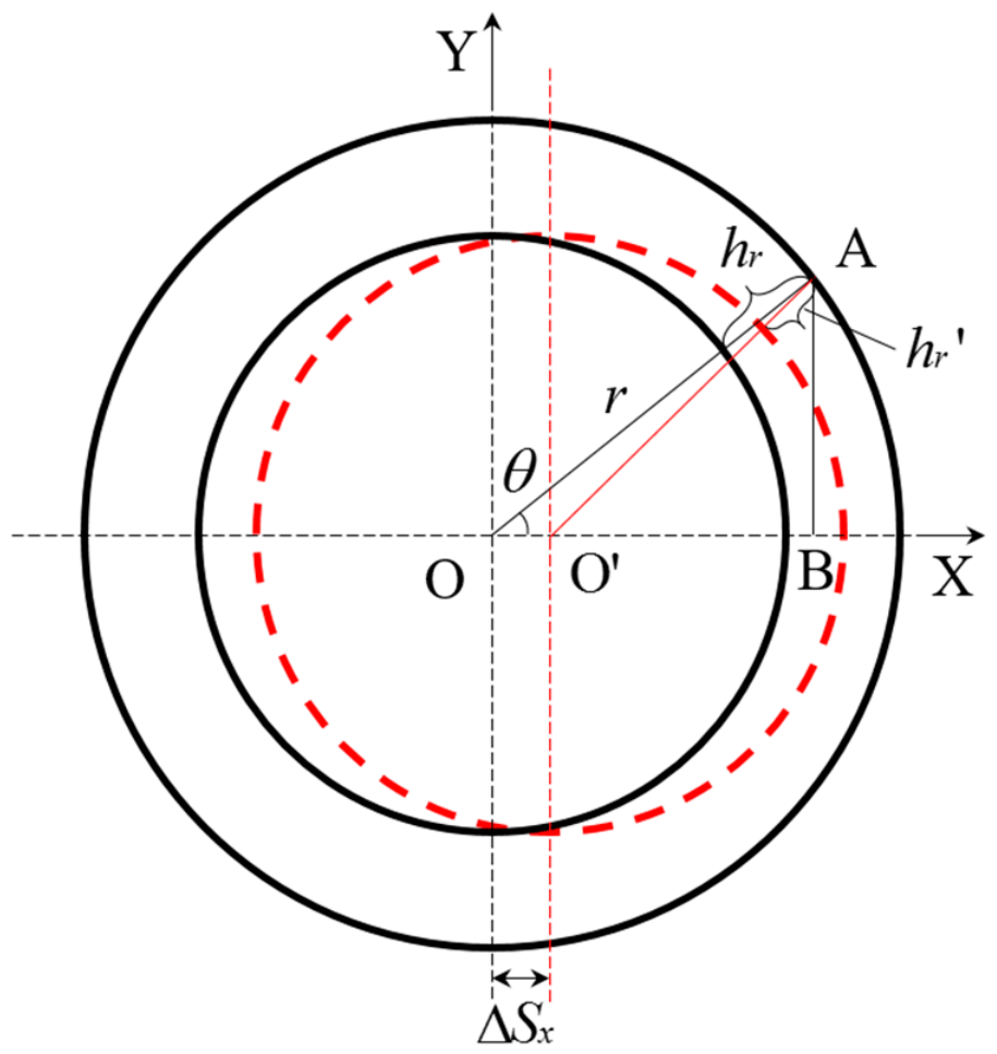
When X-direction displacement of the journal occurs due to error motion, the variation in radial air film thickness at any circumferential orifice of the journal bearing is illustrated in Figure 2, where hr and hr′ signify the radial air film thicknesses prior to and subsequent to error motion, respectively, with r denoting the journal radius.
Figure 2.
Air film thickness variation at journal bearing orifice.
The variation in air film thickness can be mathematically expressed as follows:
Similarly, when Y-direction displacement of the journal occurs, the variation in air film thickness is articulated as follows:
In journal bearings, despite the construction being entirely symmetrical and the initial air film thickness being uniform, the influence of micro-vibrations on film thickness variations is independent and cannot cancel out one another. Consequently, their influence is non-negligible. By superimposing the variations in air film thickness resulting from the journal’s movement in the X and Y directions onto the radial error sources, the resultant air film thickness variation at any orifice of the journal bearing is derived as illustrated in the following equations.
In the equations, Δr denotes the radial error source, with subscripts p and v representing the error source types of journal roundness and micro-vibration, respectively, while j specifies the serial number of the radial orifice. θ2 refers to the angle formed between the radial orifice and the X-axis within the XOY plane. The expressions for θ1 and θ2 are given as follows.
Here, m denotes the number of axial orifices corresponding to the upper or lower thrust bearings, n represents the number of radial orifices associated with the upper or lower sides of the journal bearing, while φz and φr signify the initial phase angles, respectively.
The aforementioned Equations (1) and (6) regarding the variations in air film thickness can be collectively represented in the following matrix form.
where
2.2. Model of Rotational Error Motion
The load capacity of an aerostatic bearing is sustained by the internal air film pressure, which is intrinsically coupled to the air film thickness. Variations in film thickness induce changes in bearing load capacity, hence causing error motions in the rotating components (journal and thrust plates) until a new equilibrium state is attained. The force equilibrium equation for the aerostatic bearing is derived from the equilibrium of spatial force systems as follows:
Here, W represents the load capacity; and denote the equivalent spring stiffness at any orifice of the upper and lower thrust bearings, respectively, and are abbreviated as kzt and kzb; represents the equivalent spring stiffness at any orifice of the journal bearing, abbreviated as krr. These parameters relate to the global axial stiffness Kz and global radial stiffness Kr of the aerostatic bearing via the following expressions:
where Kzt and Kzb denote the stiffness of the upper and lower thrust bearings, respectively. Substituting Equations (8)–(10) into the force equilibrium Equation (11) yields the error motion model of the rotary stage as follows:
Matrix A constitutes the stiffness matrix of the error motion model, encapsulating the stiffness properties of the equivalent springs, while Matrix b represents the disturbance matrix, incorporating error sources such as machining inaccuracies and micro-vibrations. The error motion arises from the transmission of these disturbances via the stiffness matrix. Their combination governs the extent of the error motion. Solving Equation (13) yields the error motion x.
The core assumptions of the model are valid under typical precision operating conditions: the amplitude of error motion is far smaller than the average air film thickness (generally less than 10% of the nominal film thickness), the supply pressure remains stable, and the rotational speed is low, such that static stiffness dominates the bearing performance. Nonlinear effects will become significant and degrade model accuracy under the following operating conditions:
- Large eccentricity or large error motion: When the error amplitude exceeds 20% of the average air film thickness, the nonlinear relationship between bearing stiffness and film thickness becomes prominent. The linear superposition principle is no longer applicable, and the prediction deviation of the model will increase obviously;
- High rotational speed: At high rotating speeds, the centrifugal force of the rotor and the air inertia effect will distort the air film pressure distribution. The static force equilibrium hypothesis is no longer fully valid, and dynamic nonlinear effects account for a growing proportion of error motion;
- Ultra-thin air film condition: When the air film thickness is close to the magnitude of surface roughness, air rarefaction effect and nonlinear squeeze effect induced by surface topography appear, leading to the failure of the linear equivalent spring model.
3. Analysis of Error Motion
3.1. Analysis of Error Sources and Modeling of Equivalent Stiffness
The prior research indicates that precise quantification of error motion requires clear identification of error sources and the bearing stiffness magnitudes. Considering geometric inaccuracies as one such error source, the form error of thrust bearings and journal roundness are hypothesized to conform to a normal distribution [27]. The error function is formulated as follows:
where σa and σr denote the standard deviations of the form error of thrust bearings and the roundness of the journal bearing, respectively.
This study examines an orifice-restricted aerostatic rotary stage, a structure commonly utilized in industrial applications, with bearing structural specifications specified in Table 1. In this context, d denotes the orifice diameter, while hr0 and hz0 represent the initial radial and axial air film thicknesses, respectively (i.e., the unloaded film thicknesses excluding bearing weight effects).
Table 1.
Bearing structural parameters.
The pressure distribution within an aerostatic bearing conforms to the general form of the Reynolds equation [28]:
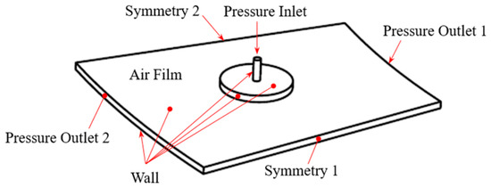
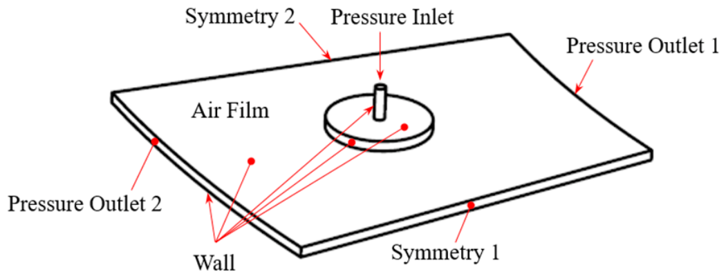
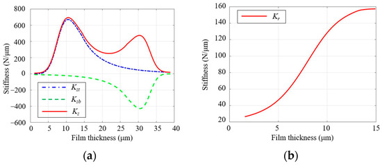
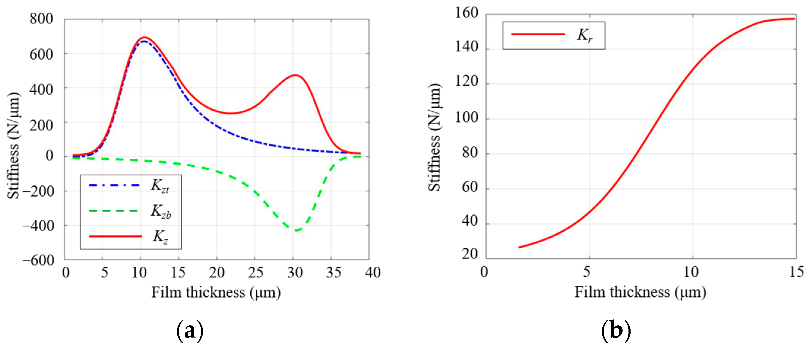
In the equation, h represents the air film thickness, p denotes the air film pressure, Q signifies the mass flow factor, and Λx and Λz are the dimensionless bearing factors. δj takes the value of 1 within the restrictor and 0 elsewhere, while the overbar “—” denotes the dimensionless representation of each variable. The air film pressure distribution is computed utilizing CFD simulations based on the aforementioned equation. The flow field is solved via the finite volume method with the SIMPLEC algorithm and a second-order upwind scheme. The SST k-ω turbulence model is adopted, and convergence is defined as residuals below 10−6 with load capacity and mass flow rate fluctuations within 0.1%. Figure 3 illustrates the boundary conditions of the simulation model for the upper thrust bearing, with analogous circumstances for the remaining components. The supply pressure is set to Ps = 0.5 MPa. This pressure is a mainstream working pressure adopted in industrial ultra-precision orifice-restricted aerostatic rotary stages for semiconductor metrology. Under this pressure, the bearing can achieve balanced load capacity, bearing stiffness and low turbulence intensity. The bearing load capacity W is derived by integrating the pressure p throughout the bearing surface. The bearing stiffness is ultimately determined using the finite-difference method, with the calculation formula given in Equation (16), and the results are illustrated in Figure 4. The formula for determining the equivalent spring stiffness is outlined in Equation (12). For kzt and kzb, the stiffness values of the upper and lower thrust bearings must be computed separately.
Figure 3.
Boundary conditions for the upper thrust bearing.
Figure 4.
Bearing stiffness characteristics: (a) axial stiffness of the thrust bearings; (b) radial stiffness of the journal bearing.
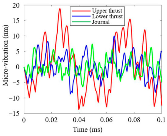
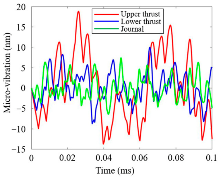
The turbulence within the aerostatic bearing induces a micro-vibration phenomenon, causing disturbance to the moving components of the bearing. To conduct an in-depth analysis of this phenomenon, the bidirectional fluid–structure interaction method was employed to compute the micro-vibration of the bearing’s moving components, with a 1 × 10⁻⁶ s time step, covering over 20 cycles for stable statistics. Mesh independence is verified across three sets with local refinement at the orifice outlet, and the amplitude deviation from the densest mesh is less than 2%. Convergence is defined by flow residuals and less than 3% amplitude fluctuation over five consecutive cycles. The SST k-ω model with enhanced wall treatment captures vortex shedding and pressure fluctuation at the orifice jet—the core micro-vibration excitation. The displacements next to the orifice outlets were extracted individually, with the results depicted in Figure 5. The variation in micro-vibration exhibits irregular fluctuations. Furthermore, since the upper thrust air film is thicker than that of the lower thrust, the amplitude of the micro-vibration is correspondingly slightly greater.
Figure 5.
Micro-vibration analysis results.
3.2. Error Motion Analysis
Assuming both 3σa and 3σr to be 0.1 μm (indicating that the confidence probability of Δap and Δrp falls within ±0.1 μm is 99.73%, which can be approximated as a PV value of 0.2 μm), the form error function of the thrust plate and the roundness error function of the journal were constructed according to Equation (14). The aforementioned functions, along with the micro-vibration and stiffness values computed in the previous section, were integrated into the error motion analysis model (13). Figure 6 shows the predicted polar coordinate curves for each component of the error motion x, and Table 2 presents the computed results. It can be observed that when the machining errors of the thrust plate and journal are 200 nm, the radial error motion of the aerostatic bearing is roughly 88 nm, whereas the axial error motion is approximately 43 nm. The lubrication effect of the air film compensates for the machining errors of the bearing components, with error averaging coefficients of roughly 1/2 and 1/5, respectively.
Figure 6.
Polar curves of analysis results for error motion: (a) radial error motion Δx, (b) radial error motion Δy, (c) tilt error motion Δα, (d) tilt error motion Δβ, and (e) axial error motion Δz.
Table 2.
Analysis results of the error motion.
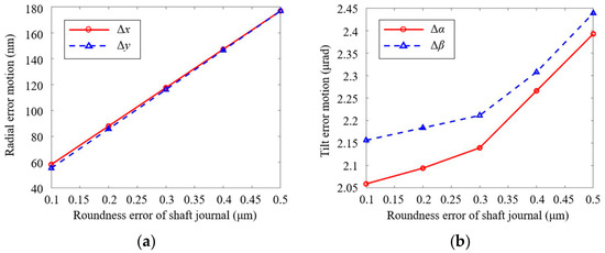
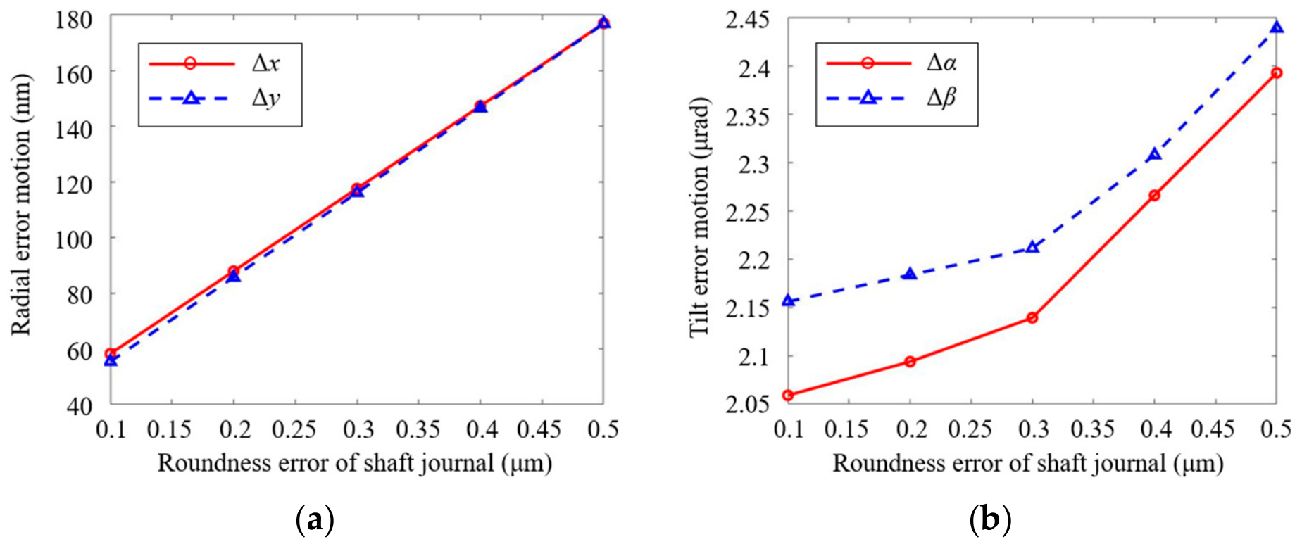
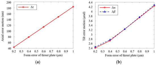
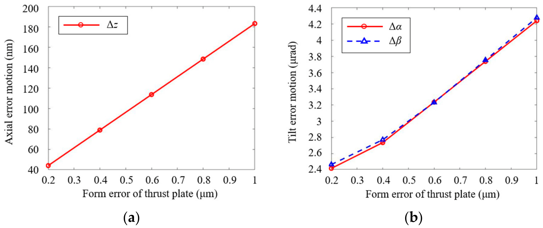
To further investigate the influence of machining errors on error motion, while maintaining constant parameters, a series of functions describing thrust plate form errors and journal roundness errors with varying amplitudes was constructed for analysis. Figure 7 depicts the influence of journal roundness on radial error motions (Δx, Δy) and tilt error motions (Δα, Δβ). Both radial and tilt error motions demonstrate an increasing tendency as the journal roundness error intensifies. Likewise, Figure 8 illustrates that thrust plate form errors exhibit a similar tendency in their influence on error motions. The distinction, however, is in the observation that thrust plate form errors do not induce significant variations in radial error motions, yet they exert a pronounced effect on the axial error motion Δz.
Figure 7.
Effect of journal roundness on (a) radial error motion and (b) tilt error motion.
Figure 8.
Effect of thrust plate form on (a) axial error motion and (b) tilt error motion.
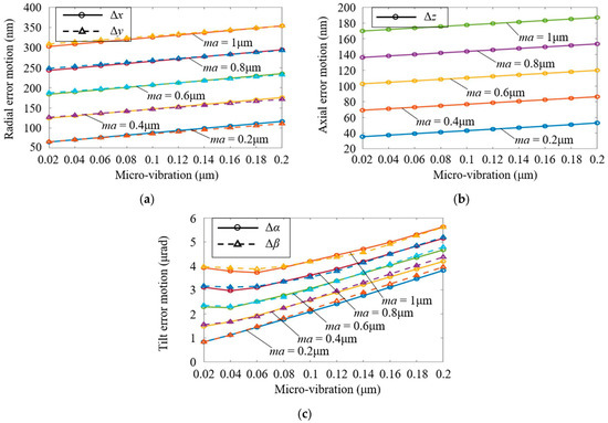
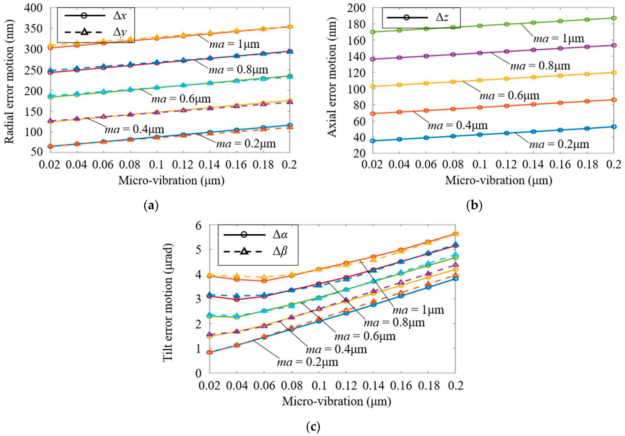
Figure 9 depicts the influence of micro-vibration on error motions, with curves categorized by bearing machining accuracy (abbreviated as “ma”). Each curve group is generated by maintaining a specific machining error amplitude constant while varying only the micro-vibration amplitude to compute error motion curves, and this process is repeated for other machining error amplitudes. Observations indicate that error motions generally increase with rising micro-vibration. Taking tilt error motion as an example, several inflection points are present in the curve. Analysis indicates that these inflection points occur when the amplitudes of micro-vibration and bearing machining error are close but opposite in sign. As concurrent error sources, they partially cancel out one another, reducing the overall amplitude of the resultant error. This is verified by the rightward shift in the inflection points as the amplitudes of micro-vibration and bearing machining error increase. When the machining error amplitude ma = 0.6 μm, the inflection point is located near the horizontal coordinate of 0.04 μm micro-vibration amplitude; when ma increases to 1 μm, the inflection point shifts rightwards to around 0.06 μm on the horizontal axis. To the right of the inflection points, the curve rises more gradually with increasing amplitude of bearing machining error, implying that micro-vibration is overshadowed when its amplitude is far smaller than that of bearing machining error. In this case, the error motion is dominated by bearing machining error. When their amplitudes are comparable, however, the influence of micro-vibration becomes significant, and error motion is concurrently governed by both error sources.
Figure 9.
Effect of micro-vibration on (a) radial error motion, (b) axial error motion and (c) tilt error motion.
To further analyze the aforementioned occurrences, an error influence factor (as defined in Equation (17)) is introduced, with the computation results presented in Table 3. This factor varies from 0 to 1, with larger values signifying more significant micro-vibration impacts on error motions. Observations reveal that when bearing machining errors exhibit larger amplitudes (associated with increased error motions), the error influence factor λ decreases. In contrast, λ increases significantly with minor machining errors, reaching values as high as approximately 0.8. Consequently, for high-precision aerostatic rotary stages requiring error motions beneath the sub-100 nm level, the influence of micro-vibration becomes apparent and demands considerable focus.
Table 3.
Computation results of the error influence factor.
4. Experimental Verification
4.1. Experimental Setup
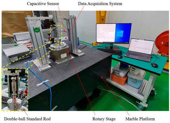
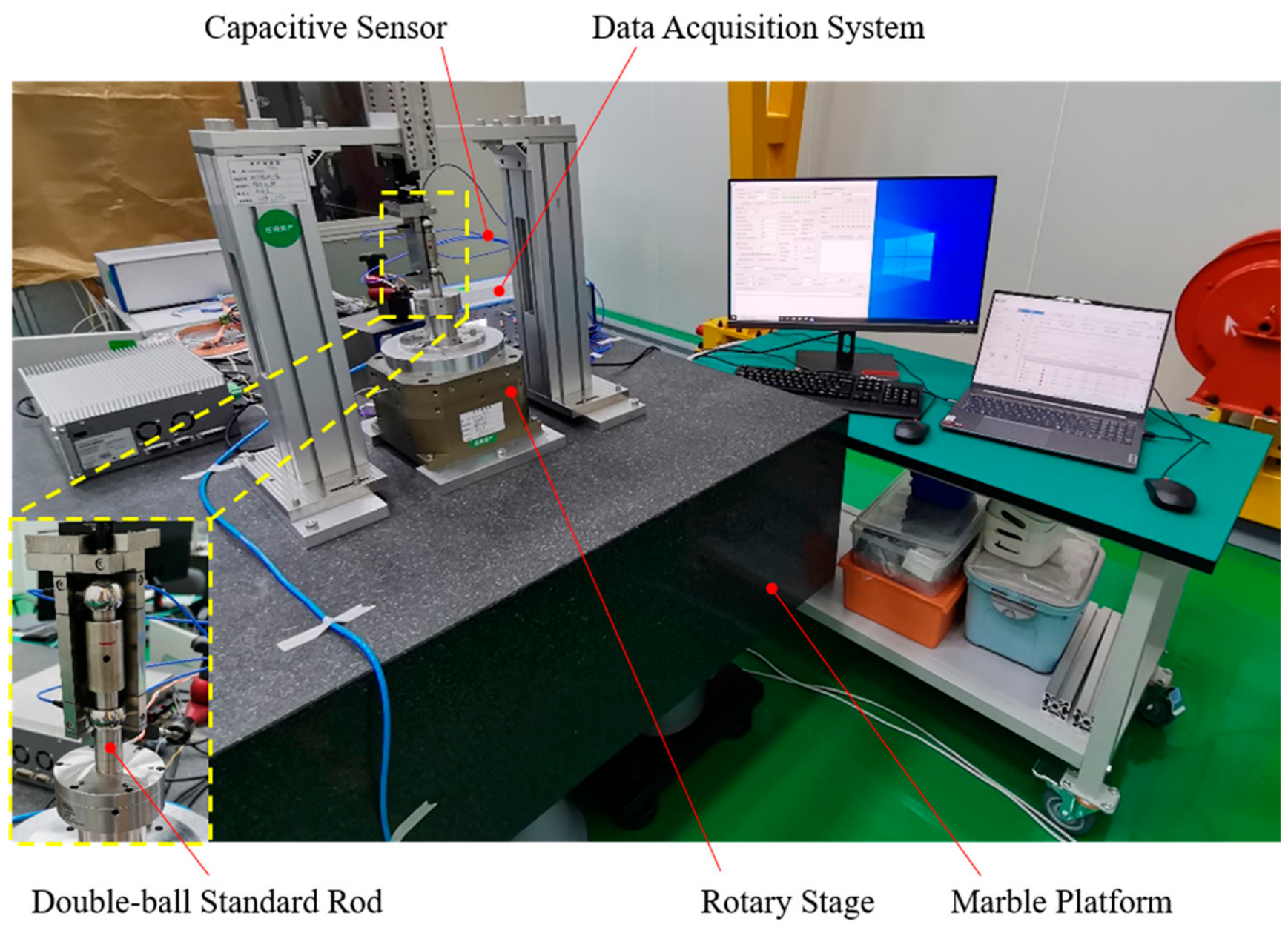
An experimental setup, illustrated in Figure 10, was developed to validate the previously observed error motion analysis results. The testing apparatus comprises the measured rotary stage, a double-ball standard rod, capacitive sensors, and a data acquisition system. The measured rotary stage is a self-engineered externally pressurized aerostatic rotary stage. A double-ball standard rod is mounted on top of the rotary stage, encircled by five high-precision capacitive sensors arranged via a dedicated fixture. Each ball is equipped with two capacitive sensors positioned orthogonally along radial directions on its equatorial plane to measure radial error motions (Δx, Δy). The fifth sensor is positioned axially above the upper ball to measure axial error motion (Δz). Error separation and data processing were performed utilizing the reversal method [29,30], which is extensively employed in engineering applications. The roundness error of the artifact was separated from the measured data, and the tilt error motions Δα and Δβ were computed.
Figure 10.
Experimental setup for error motion measurement.
The double-ball standard rod, a high-precision inspection instrument developed by Lion Precision, demonstrates a roundness of less than 30 nm for each individual ball. The experiment was performed in an environmentally controlled laboratory (±0.1 °C, VC-E vibration grade). The measurement system employed five Micro-Epsilon CSH02 high-precision capacitive displacement sensors featuring a ±100 μm measurement range with an exceptional 0.4 nm resolution. The sensors were connected to a dedicated Micro-Epsilon NCDT6530 data acquisition device (manufactured in Ortenburg, Germany) operating at a sampling frequency of 62.5 Hz. The precision rotary stage was driven at a constant speed of 10 rpm, achieving an angular sampling density of approximately one data point per degree. Data acquisition began following rotational stabilization, with the system performing continuous multi-revolution data capture cycles to provide an adequate dataset for subsequent signal processing and analysis.
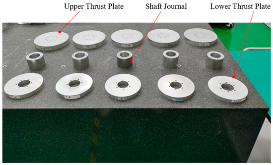
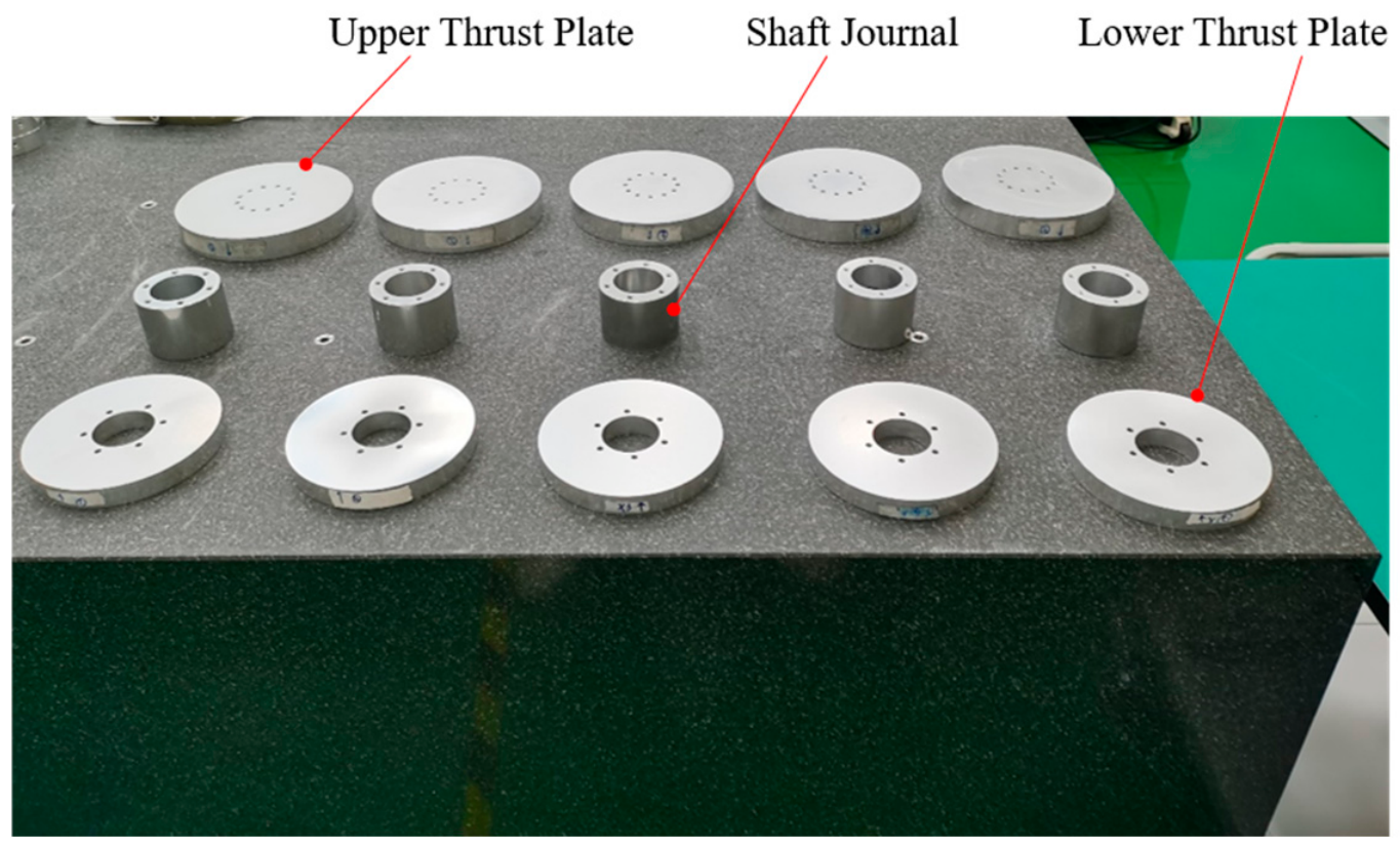
A series of bearing components with varying precision levels was machined by grinding processes to investigate the influence of machining errors on error motions, as shown in Figure 11. The amplitudes of the thrust plate form error and journal roundness error are mostly identical to those constructed in the preceding section. Table 4 presents the actual measurements of machining accuracy for thrust plates and journals. During error motion experiments, the influence patterns of machining errors were methodically evaluated by substituting thrust plates or journals with components of varying precision grades while maintaining identical configurations for all other structures.
Figure 11.
Photograph of machined bearing components.
Table 4.
Measurement results of machined bearing components.
4.2. Experimental Results and Discussion
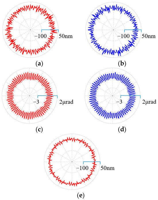
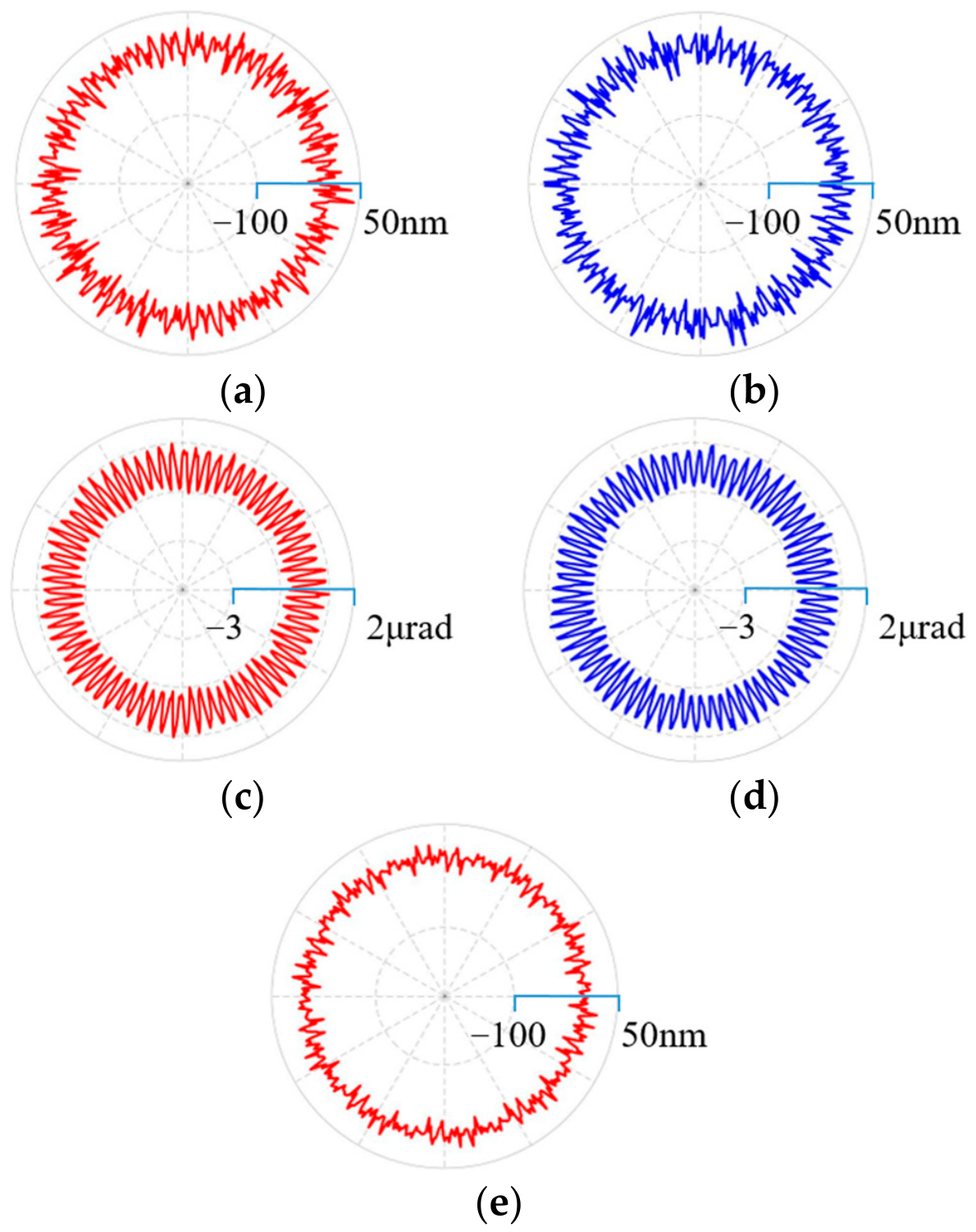
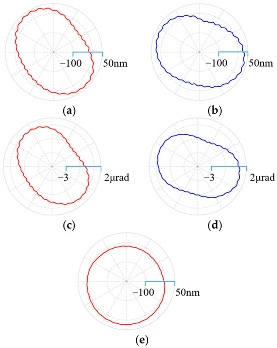
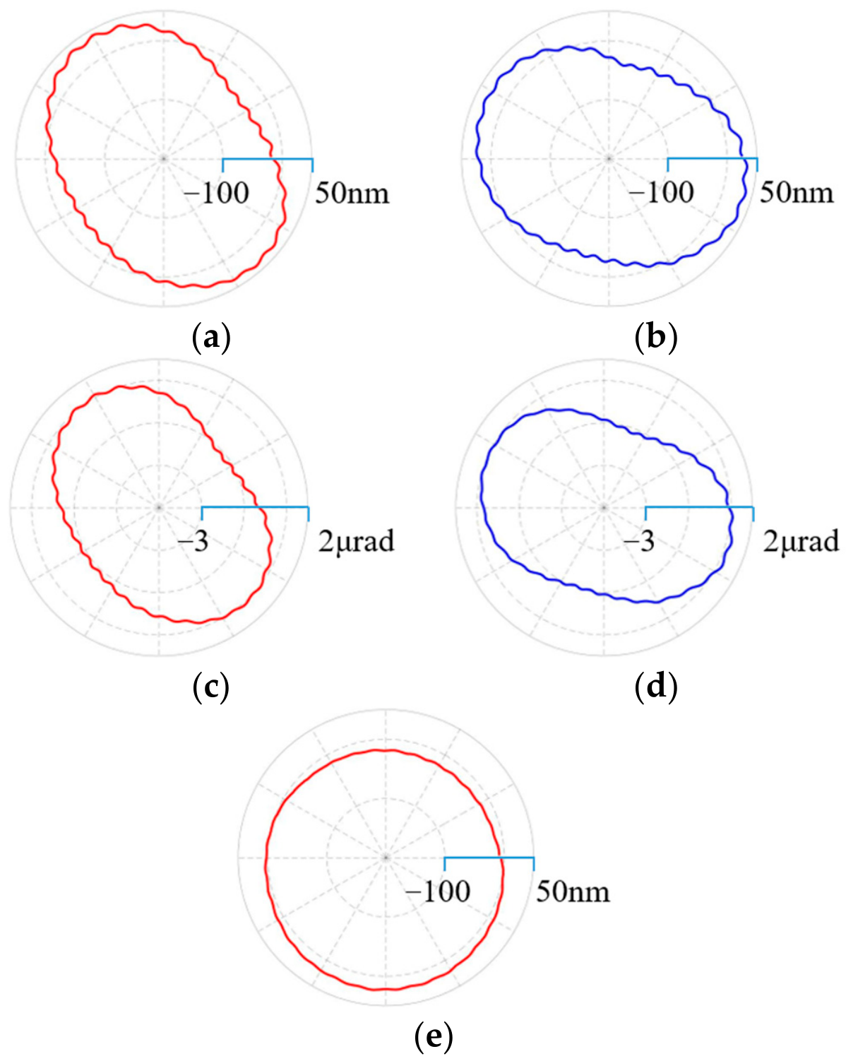
The bearing assembly, consisting of the thrust plate from Row 1 and the journal from Row 2 of Table 4, was assembled on the aerostatic rotary stage, and error motion tests were performed following the experimental configuration described in Section 4.1. Figure 12 illustrates the polar coordinate curves of the error motion components, and Table 5 presents the measured results of each error component. For comparative purposes, the analysis results from Table 2 are included here as well. The analytical values of error motions nearly correspond with experimental values, with relative errors not exceeding 15%. This indicates that the established error motion model can effectively assess the error motions of aerostatic bearings. Minor discrepancies between analytical and experimental values primarily stem from the following factors: slight differences between machining errors of thrust plates/journals and form/roundness errors constructed in the simulation, probe installation accuracy, and separation precision of standard ball roundness, etc.
Figure 12.
Polar curves of experiment results for error motion: (a) radial error motion Δx, (b) radial error motion Δy, (c) tilt error motion Δα, (d) tilt error motion Δβ, and (e) axial error motion Δz.
Table 5.
Analysis and experiment results of the error motion.
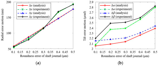
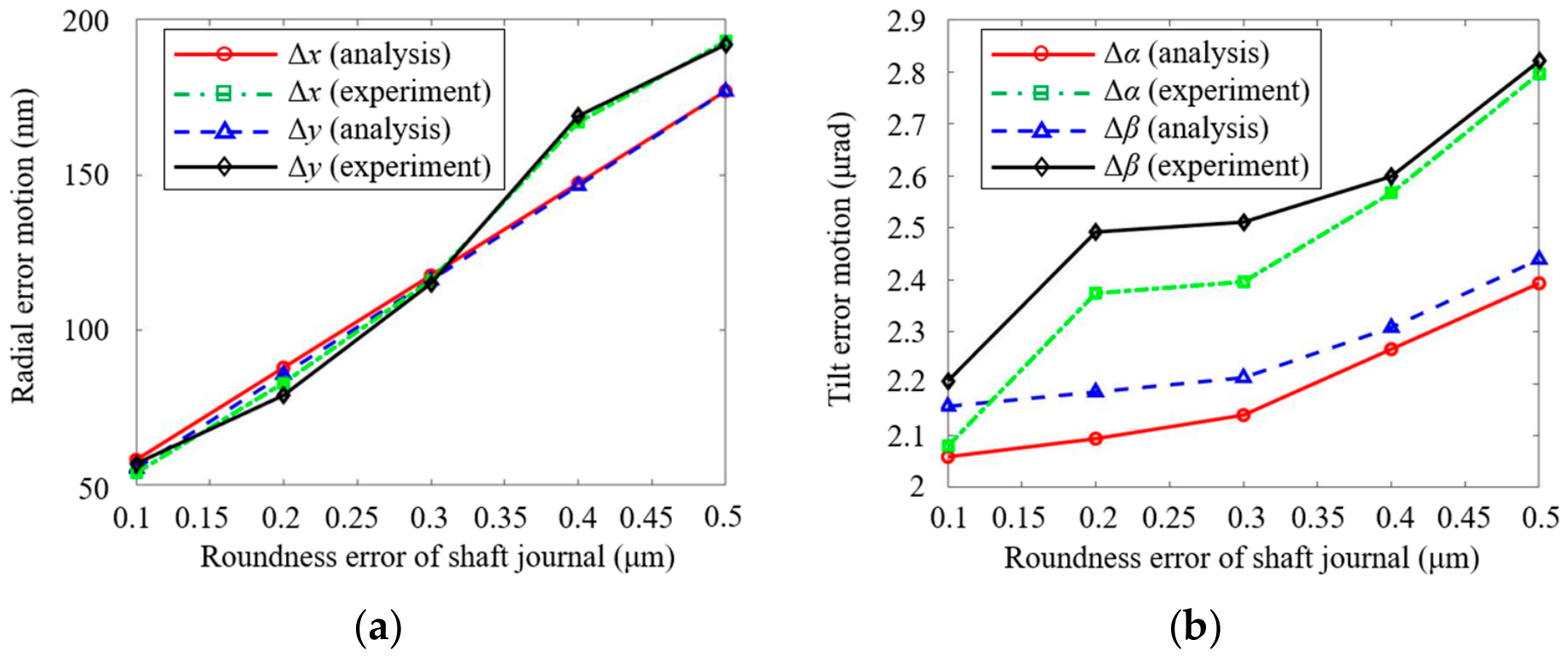
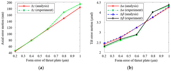
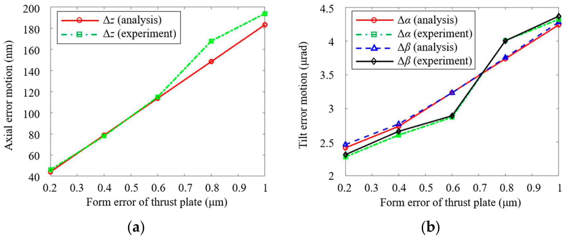
With the thrust plate corresponding to Row 1 of Table 4 kept constant, journals with different precision levels from the remaining rows were assembled in sequence. The same measurement and data processing protocol was applied to all test groups to derive the variation curves illustrating the effect of journal roundness on error motions, as shown in Figure 13. For comparison, the analytical curves of the error motion from Section 3.2 are also presented. The trends of both curves are well aligned, with error motion magnitudes roughly identical. Notably, larger journal roundness corresponds to increased radial and tilt error motions, while the error averaging coefficient remains relatively stable at approximately 1/2 to 1/3. Likewise, with the journal fixed to Row 1 of Table 4, substitute the thrust plate with each of the remaining rows and mount the assembly onto the aerostatic rotary stage for error motion measurements. Figure 14 shows the resulting curves depicting the impact of thrust plate form on error motions. The conclusions drawn here are entirely analogous to those of Figure 13 and thus not reiterated. Collectively, these results demonstrate that bearing manufacturing errors significantly affect error motions, exhibiting a distinct positive correlation. The consistent variation trends between analytical and experimental error motion curves further validate the rationality of the established error motion analysis model.
Figure 13.
Effect of journal roundness on (a) radial error motion and (b) tilt error motion.
Figure 14.
Effect of thrust plate form on (a) axial error motion and (b) tilt error motion.
Given the inherently multifaceted nature of micro-vibration origins, altering micro-vibration amplitudes concurrently induces changes in other bearing characteristic parameters. Consequently, experimentally validating the exclusive correlation between micro-vibration variations and error motions is challenging. Nevertheless, the preceding experimental phases have conclusively verified the feasibility of the error motion analysis model. Therefore, the analytical conclusions regarding the correlations between micro-vibration and error motion presented in Section 3.2 are considered valid. The error motion analysis results of error sources, including micro-vibration, derived from the model established in this paper remain applicable for evaluating error motions in high-precision aerostatic rotary stages.
5. Conclusions
This paper establishes an analytical model for error motions in aerostatic bearings, grounded in the principles of linear superposition and spatial force equilibrium relationships. The model was utilized to examine the error motions of an orifice-restricted aerostatic rotary stage, accompanied by experimental validation. The main conclusions of this study can be summarized as follows:
- Journal roundness significantly affects error motions. Greater roundness correlates with increased radial and tilt error motions, with an error averaging coefficient of roughly 1/2 to 1/3.
- Thrust plate form errors substantially influence error motions. Larger form errors lead to increased axial and tilt error motions, exhibiting an error averaging coefficient of around 1/5.
- Analytical and experimental error motion values demonstrate good agreement, with relative errors remaining below 15%. This validates the model’s suitability for predicting error motions in precision aerostatic rotary stages.
- In ultra-precision aerostatic rotary stages necessitating sub-100 nm error motion accuracy, micro-vibration effects cannot be neglected. Comprehensive consideration of micro-vibrations and bearing manufacturing inaccuracies is essential.
The error motion modeling methodology proposed in this study enables comprehensive and accurate prediction of all five components of bearing error motion during the design phase of aerostatic rotary stages. This method significantly enriches the approaches for assessing the error motions of precision aerostatic shaft systems, providing both critical theoretical references and substantial engineering utility for improving rotary stage accuracy while reducing development lead time.
Author Contributions
Conceptualization, X.Z. (Xiaofeng Zheng) and X.Z. (Xiangyu Zhao); methodology, X.Z. (Xiaofeng Zheng) and T.Z.; software, X.Z. (Xiaofeng Zheng) and D.Z.; validation, X.Z. (Xiaofeng Zheng) and C.L.; formal analysis, X.Z. (Xiaofeng Zheng); investigation, X.Z. (Xiaofeng Zheng); data curation, X.Z. (Xiaofeng Zheng) and X.Z. (Xiangyu Zhao); writing—original draft, X.Z. (Xiaofeng Zheng); writing—review and editing, L.Z. and D.M.; visualization, T.D.; supervision, L.Z. and D.M.; project administration, L.Z.; funding acquisition, L.Z. All authors have read and agreed to the published version of the manuscript.
Funding
This research was supported by the Jilin Province Science and Technology Development Plan Project of China (No.20250602030RC), the Jilin Province Science and Technology Development Plan Project of China (No.20260602019RC), and the Jilin Province Science and Technology Development Plan Project of China (No.20220201044GX).
Institutional Review Board Statement
Not applicable.
Informed Consent Statement
Not applicable.
Data Availability Statement
The original contributions presented in this study are included in the article. Further inquiries can be directed to the corresponding author.
Acknowledgments
The authors gratefully acknowledge Hang Yu for his support in providing resources during the course of this research.
Conflicts of Interest
Authors Xiaofeng Zheng, Xiangyu Zhao, Tianhao Zheng, Daowei Zhang, Lei Zhang, Cheng Li and Tianyang Dong were employed by the company Chang Guang Satellite Technology Co., Ltd. The remaining authors declare that the research was conducted in the absence of any commercial or financial relationships that could be construed as a potential conflict of interest.
References
- Yang, X.; Yu, X.; Jiang, H.; Gao, W.; Dai, R.; Jia, W.; Jiao, J.; Wang, J. Potential fields in hydrostatic bearing spindle: Review and recent advances of rotational accuracy. Int. J. Adv. Manuf. Technol. 2025, 138, 5097–5121. [Google Scholar] [CrossRef] [Scilit]
- Yabe, H. A study on run-out characteristics of externally pressurized gas journal bearing: Rotor run-out characteristics. JSME Int. J. 1994, 37, 355–361. [Google Scholar] [CrossRef] [Scilit]
- Zhang, G.; Huang, M.; Chen, G.; Li, J.; Liu, Y.; He, J.; Zheng, Y.; Tang, S.; Cui, H. Design and optimization of fluid lubricated bearings operated with extreme working performances—A comprehensive review. Int. J. Extrem. Manuf. 2024, 6, 022010. [Google Scholar] [CrossRef] [Scilit]
- Sun, F. An analytical study on the rotational accuracy of aerostatic journal bearing. Chin. J. Sci. Instrum. 1991, 12, 324–328. [Google Scholar] [CrossRef] [Scilit]
- Akira, K.; Masakzu, M. Effects of part accuracy on rotational accuracy in hydrostatic bearing. J. Jpn. Soc. Precis. Eng. 1979, 45, 1174–1176. [Google Scholar] [CrossRef]
- Hwang, J.; Shim, J.; Park, C.-H. Estimation of rotational motion accuracy for rotary units. J. Korean Soc. Precis. Eng. 2015, 32, 127–133. [Google Scholar] [CrossRef] [Scilit]
- Zhang, P.; Zha, J. Dynamic accuracy model of porous journal air bearing considering rotational speed. Tribol. Int. 2021, 161, 107064. [Google Scholar] [CrossRef] [Scilit]
- Chen, D.; Zhang, X.; Pan, R.; Sun, K.; Fan, J. Research on the Dynamic Performance of Aerostatic Radial Bearings with Elastic Throttles. J. Mech. Eng. 2025, 61, 74–86. [Google Scholar] [CrossRef] [Scilit]
- Hu, C.; Xiong, W.; Sun, W.; Yuan, S. Research on the Mechanism of Improving Hydrostatic Spindle Rotating Accuracy with Controllable Restrictor. J. Mech. Eng. 2019, 55, 160–168. [Google Scholar] [CrossRef] [Scilit]
- Xiong, W.; Yuan, S.; Hu, C.; Wang, J.; Fan, L.; Lei, Q. The Laws and Ultimate Prediction of Rotation Accuracy for Hydrostatic Spindle. J. Mech. Eng. 2021, 57, 70–82. [Google Scholar] [CrossRef] [Scilit]
- Meng, S. Research on the Rotary Accuracy of the Hydrostatic-dynamic Spindle Affected by Journal Geometric Error and Electromagnetic Eccentricity. Ph.D. Thesis, Hunan University, Changsha, China, 2016. [Google Scholar]
- Meruane, V.; Pascual, R. Identification of nonlinear dynamic coefficients in plain journal bearings. Tribol. Int. 2008, 41, 743–754. [Google Scholar] [CrossRef] [Scilit]
- Cappa, S.; Reynaerts, D.; Al-Bender, F. Reducing the radial error motion of an aerostatic journal bearing to a nanometre level: Theoretical modelling. Tribol. Lett. 2014, 53, 27–41. [Google Scholar]
- KIM, K.-M.; Kim, K.-W. An analytical study on the rotational accuracy of externally pressurized air journal bearing. JSME Int. J. 1992, 35, 485–492. [Google Scholar] [CrossRef] [Scilit]
- Wang, W.; Song, P.; Yu, H.; Zhang, G. Study on Static Characteristics of Ultra-Precision Aerostatic Motorized Spindle under Gas–Magnetic Field Coupling. Electronics 2022, 11, 1434. [Google Scholar] [CrossRef] [Scilit]
- Cui, H.; Wang, Y.; Yue, X.; Huang, M.; Wang, W.; Jiang, Z. Numerical analysis and experimental investigation into the effects of manufacturing errors on the running accuracy of the aerostatic porous spindle. Tribol. Int. 2018, 118, 20–36. [Google Scholar] [CrossRef] [Scilit]
- Zhang, G.; Zheng, J.; Yu, H.; Chen, T.; Shan, S.; Peng, C. Influence of shape errors and inertia effects on the error motion of the aerostatic spindle. Proc. Inst. Mech. Eng. Part J J. Eng. Tribol. 2024, 238, 260–271. [Google Scholar]
- Shi, J.; Feng, X.; Cao, H. Influence of angular misalignment and triangular surface waviness on the performance of hybrid air journal bearings. Ind. Lubr. Tribol. 2025, 77, 845–858. [Google Scholar] [CrossRef] [Scilit]
- Jia, S.; Jia, C.; Lu, Y. Dynamic Modeling of 5-DOF Aerostatic Bearing Rotor System with Adjustable Gas Film Gap. Lubricants 2024, 12, 424. [Google Scholar] [CrossRef] [Scilit]
- Bhat, N.; Kumar, S.; Tan, W.; Narasimhan, R.; Low, T.C. Performance of inherently compensated flat pad aerostatic bearings subject to dynamic perturbation forces. Precis. Eng. 2012, 36, 399–407. [Google Scholar] [CrossRef] [Scilit]
- Zhu, J.; Chen, H.; Chen, X. Large eddy simulation of vortex shedding and pressure fluctuation in aerostatic bearings. J. Fluids Struct. 2013, 40, 42–51. [Google Scholar] [CrossRef] [Scilit]
- Li, Y.; Zhao, J.; Zhu, H.; Lin, Y. Numerical analysis and experimental study on the microvibration of an aerostatic thrust bearing with a pocketed orifice-type restrictor. Proc. Inst. Mech. Eng. Part J J. Eng. Tribol. 2015, 229, 609–623. [Google Scholar]
- Li, Y. Mechanical Performances Analysis and Parameters Design Optimization of the Aerostatic Bearing with Orifice Type Restrictor. Ph.D. Thesis, China Academy of Engineering Physics, Mianyang, China, 2018. [Google Scholar]
- Yabe, H.; Ishida, H. A study on the running accuracy of an externally pressurized gas thrust bearing: Rotor run-out characteristics. JSME Int. J. 1991, 34, 333–338. [Google Scholar] [CrossRef] [Scilit]
- Yin, J. Separated Aerostatic Bearings and Its Mechanism of Error Averaging. Master’s Thesis, China Jiliang University, Hangzhou, China, 2013. [Google Scholar]
- Jin, S. Modeling and Experimental Study on Rotation Error of Aerostatic Bearing. Master’s Thesis, Harbin Institute of Technology, Harbin, China, 2022. [Google Scholar]
- Traband, M.T.; Medeiros, D.; Chandra, M.J. A statistical approach to tolerance evaluation for circles and cylinders. IIE Trans. 2004, 36, 777–785. [Google Scholar] [CrossRef] [Scilit]
- Liu, T.; Liu, Y.; Chen, S. Hydrostatic Gas Lubrication; Harbin Institute of Technology Press: Harbin, China, 1990. [Google Scholar]
- Evans, C.J.; Hocken, R.J.; Estler, W.T. Self-calibration: Reversal, redundancy, error separation, and ‘absolute testing’. CIRP Ann. 1996, 45, 617–634. [Google Scholar] [CrossRef] [Scilit]
- Donaldson, R.R. A simple method for separating spindle error from test ball roundness error. Ann. CIRP 1972, 21, 125. [Google Scholar]

Disclaimer/Publisher’s Note: The statements, opinions and data contained in all publications are solely those of the individual author(s) and contributor(s) and not of MDPI and/or the editor(s). MDPI and/or the editor(s) disclaim responsibility for any injury to people or property resulting from any ideas, methods, instructions or products referred to in the content. |
© 2026 by the authors. Licensee MDPI, Basel, Switzerland. This article is an open access article distributed under the terms and conditions of the Creative Commons Attribution (CC BY) license.