


Abstract
A reduced-order framework was developed to describe the outlet initial conditions of a pressure-swirl nozzle under reduced-gravity conditions and to clarify how gravity modifies the nozzle-exit state relative to the corresponding 1 g baseline. Under normal gravity, the baseline outlet state was established through CFD-informed identification of the discharge coefficient and initial spray cone angle, from which the outlet axial and tangential velocity components were reconstructed. Gravity-induced deviations were then introduced through compact correction relationships for the outlet descriptors and liquid-film geometry. The outlet parameters were evaluated over pressure drops of 0.1–0.5 MPa and gravity levels from 1 g to 10−5 g. The results indicate that operating pressure mainly determines the baseline outlet state, whereas reduced gravity acts primarily as a correction to that baseline. Under forward-gravity injection, decreasing gravity reduces the axial and tangential velocity components, discharge coefficient, and initial spray cone angle, while increasing the outlet liquid-film thickness. A CFD-based comparison at 0.3 MPa indicates that the framework captures the first-order trends of normalized outlet velocity components and liquid-film thickness within the investigated conditions. Independent experimental validation is not included in this study and remains necessary for future quantitative assessment.
1. Introduction
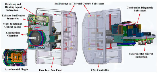
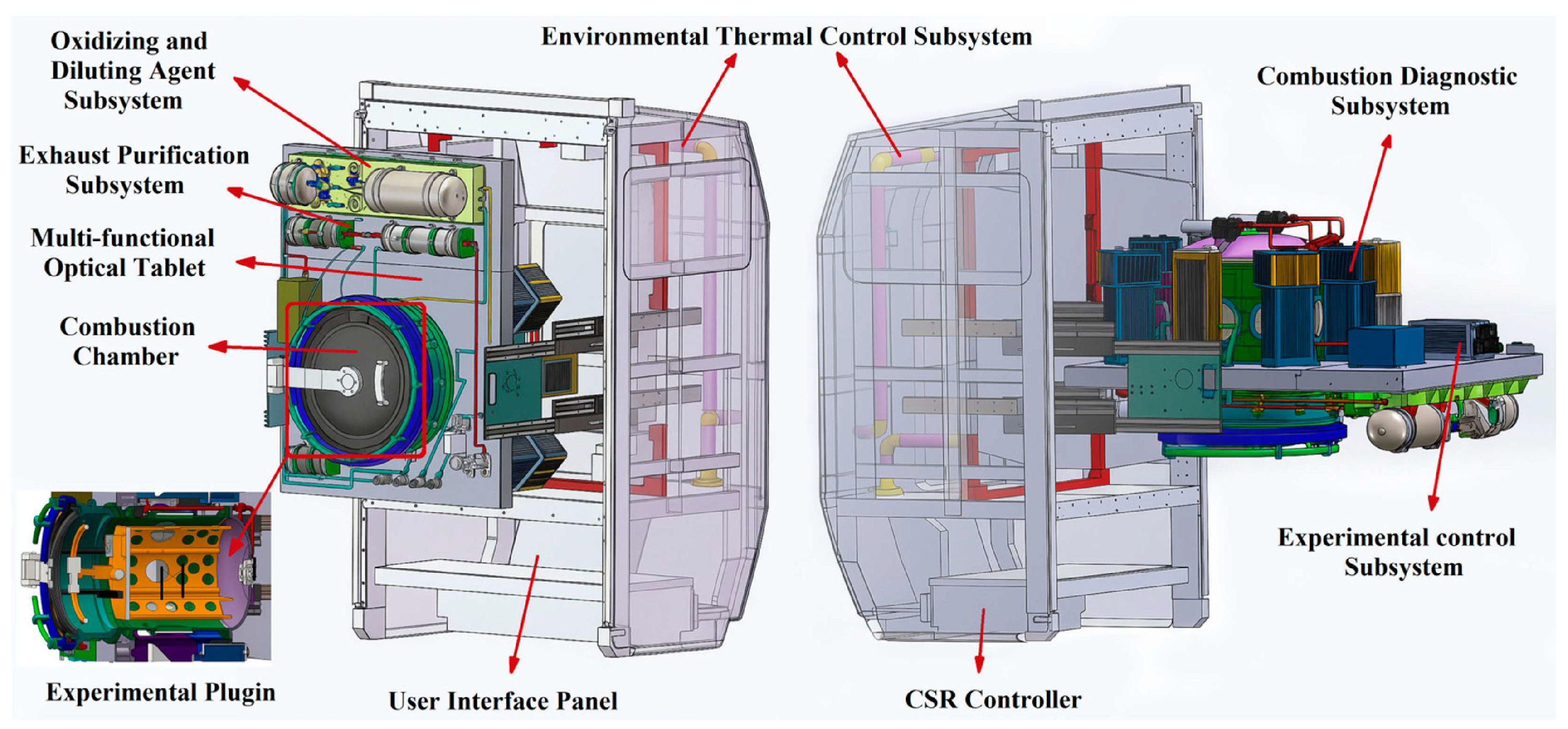
The Combustion Science Experimental System (CSES) aboard the China Space Station has provided a dedicated microgravity platform for combustion research, and its overall configuration is shown in Figure 1 [1,2,3]. The system is designed to support gaseous, liquid, and solid fuel combustion experiments, and gas-phase combustion studies have already yielded initial in-orbit results [4,5]. Extending this platform to liquid fuel combustion will require dedicated liquid experimental inserts. In this context, liquid injection and atomization become important not only for the experiments themselves, but also for the design of liquid fuel delivery systems for such inserts. For injector-based liquid fuel configurations, this requirement is reflected most directly in the nozzle-exit state, which determines the initial distribution of liquid mass, momentum, and interfacial area, and thereby affects the subsequent evolution of mixing, ignition, and combustion under microgravity.
Figure 1.
Overall configuration of the Combustion Science Experimental System (CSES) aboard the China Space Station. Adapted from Ref. [2].
Previous studies in reduced-gravity environments have shown that liquid-phase behavior can be substantially modified when gravity is weakened, and this has been examined extensively in canonical configurations such as isolated droplets and droplet combustion systems aboard space platforms [6]. Liquid-jet studies have further shown that gravity variation affects not only breakup behavior itself, but also the subsequent size, oscillation, trajectory, and motion of the generated droplets [7]. At the mechanistic level, microgravity-related analyses have also suggested that jet instability and breakup cannot always be interpreted simply as gravity-weakened extensions of normal-gravity behavior [8]. However, representative microgravity investigations have still been concentrated mainly on isolated droplets, free liquid jets, or combustion-oriented spray configurations [9], whereas the nozzle-exit state of practical atomizers has received much less direct attention under microgravity conditions. For pressure-swirl atomizers in particular, this gap is most evident in the near-nozzle region, where the exit liquid-sheet geometry and initial momentum distribution remain tightly coupled with the subsequent near-nozzle liquid-sheet evolution [10,11,12].
Among practical atomizers, pressure-swirl nozzles are of particular interest because tangential pressure-driven inflow generates strong internal swirl, promotes the formation of a central air core, and discharges the liquid as an annular film that develops into a hollow-cone spray [13,14,15]. Recent studies have further shown that the near-nozzle spray development remains strongly coupled with the exit liquid-film structure and the early-stage momentum distribution [16,17,18]. For such nozzles, the nozzle exit is not merely a geometric boundary, but the immediate interface between the internal swirling flow and the subsequent external liquid-phase evolution [19,20,21]. In practical terms, the nozzle-exit state may be described by a set of outlet initial conditions, including the air-core structure, liquid-film thickness, axial and tangential velocity components, and initial spreading direction. These parameters define the geometric and dynamic state of the discharged liquid and provide the most direct link between internal flow organization and downstream atomization behavior. As the entrance conditions for the external liquid film, they also determine the starting point for subsequent liquid-sheet expansion, instability growth, and primary breakup [22,23,24]. This linkage is particularly important because the initial film thickness, velocity distribution, and instability growth established near the nozzle exit directly condition the subsequent primary atomization process [25,26,27].
Under normal-gravity conditions, the internal flow and spray formation of pressure-swirl nozzles have been studied extensively through theoretical, experimental, and numerical approaches [28,29,30,31,32,33]. More recent work has further revisited the internal-flow dynamics and near-nozzle atomization behavior of pressure-swirl atomizers using refined experiments and higher-fidelity numerical analyses [34,35,36,37]. Existing studies have established the basic relationships among air-core formation, outlet liquid-film thickness, velocity components, discharge behavior, and spray cone angle, thereby providing a baseline understanding of how internal swirling flow governs downstream atomization [30]. In particular, theoretical analyses are valuable because they provide a basis for predicting the nozzle-exit initial conditions of the swirling liquid sheet, from which subsequent sheet expansion, instability development, and breakup into droplets proceed [33]. However, these understandings have been developed predominantly under normal-gravity conditions [29,32]. Accordingly, how gravity variation should be incorporated into the description of nozzle-exit initial conditions under microgravity remains insufficiently clarified.
In this study, a reduced-order theoretical framework is developed to describe the outlet initial conditions of a pressure-swirl nozzle under reduced-gravity conditions and is assessed by comparison with CFD simulations. Under normal-gravity conditions, the baseline nozzle-exit state is established in a CFD-informed manner using the discharge coefficient and initial spray cone angle, from which the outlet liquid-film geometry and the corresponding axial and tangential velocity components are reconstructed. Within this framework, gravity is incorporated as a correction to the baseline outlet state rather than being treated as the primary mechanism governing the internal swirling flow. On this basis, the effects of pressure drop and gravity level on the outlet parameters are analyzed for a nozzle with fixed geometry, and the model-calculated reduced-gravity outlet states are compared with CFD results under representative operating conditions. The aim is to provide a compact and physically interpretable description of nozzle-exit initial conditions under reduced gravity and to offer a reduced-order basis for subsequent analyses of external liquid-film evolution. However, the present study remains focused on near-nozzle initial conditions rather than the complete downstream spray breakup process.
2. Theoretical Model
2.1. Air-Core Structure and Outlet Liquid-Film Geometry
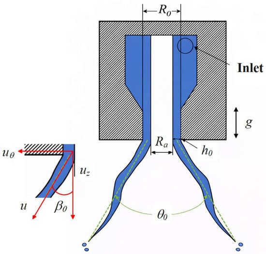
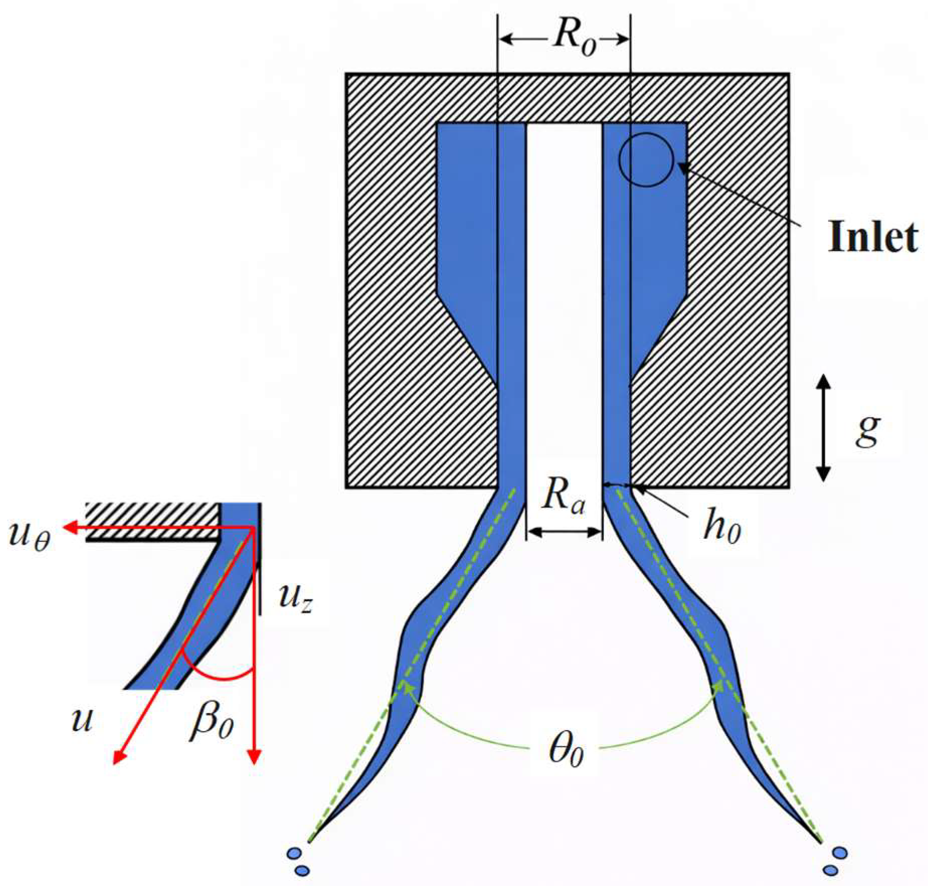
In a pressure-swirl nozzle, liquid enters the swirl chamber through tangential passages and develops a strong rotational motion inside the nozzle. The resulting radial pressure gradient lowers the pressure near the axis and may induce the formation of a central air core. Accordingly, the liquid leaves the outlet not as a full jet, but as an annular liquid film surrounding the air core. This air-core/liquid-film configuration forms the geometric and kinematic basis of the present outlet initial-condition model, as schematically illustrated in Figure 2.
Figure 2.
Schematic illustration of the outlet initial-condition model for a pressure-swirl nozzle, showing the air-core structure, annular liquid film, local velocity decomposition at the nozzle exit, initial spray cone angle, and gravity direction.
Let denote the outlet radius and the air-core radius. The dimensionless air-core radius ratio is defined as
Under the annular-film assumption, the effective flow area occupied by the liquid phase at the outlet is
By introducing , the above expression becomes
The initial outlet liquid-film thickness is approximated from the geometric difference between the outlet radius and the air-core radius, i.e.,
Using the air-core radius ratio, this relation can be rewritten as
These relations show that the air-core structure determines both the effective liquid flow area and the initial liquid-film thickness at the nozzle exit. Since the outlet liquid-film geometry serves as the geometric basis for the subsequent velocity decomposition and spray-angle formulation, the air core can be regarded as a key intermediate variable linking the internal swirling flow to the outlet initial conditions.
In the present study, these relations are used to establish a reduced-order model of the nozzle-exit state, rather than a full solution of the internal swirling flow.
2.2. Outlet Velocity Decomposition Model
After the outlet liquid-film geometry is determined, the next step is to describe its initial kinematic state. For a pressure-swirl nozzle, the outlet liquid film possesses both axial and tangential velocity components. The axial component governs the downstream transport of the discharged liquid, whereas the tangential component reflects the residual swirl intensity at the outlet and contributes to the initial spreading tendency of the annular film.
Let denote the liquid volumetric flow rate and the effective liquid flow area at the outlet. Based on mass conservation, the average axial velocity of the outlet liquid film can be written as
Substituting the effective flow area obtained in Section 2.1 gives
To further relate the outlet velocity to the pressure-driven nozzle operation, the discharge coefficient is introduced. The volumetric flow rate can be expressed as
where is the total outlet area, is the pressure drop across the nozzle, and is the liquid density. Substituting this relation into the above expression yields
In addition to the axial motion, the outlet liquid film also carries a tangential velocity component due to the internal swirling flow. Let denote the resultant outlet velocity and the angle between and the nozzle axis. The outlet velocity can then be decomposed as
Accordingly, the tangential-to-axial velocity ratio is
This formulation shows that the outlet velocity structure is determined jointly by the pressure-driven discharge level and the residual swirl intensity. Together, and define the initial dynamic condition of the annular liquid film at the nozzle exit.
2.3. Flow Coefficient and Initial Spray Cone Angle
Based on the outlet liquid-film geometry and velocity decomposition established above, two integrated parameters are further introduced to characterize the outlet initial conditions of the pressure-swirl nozzle, namely the discharge coefficient and the initial spray cone angle. The former reflects the overall flow capacity of the nozzle, while the latter describes the initial spreading direction of the outlet liquid film.
The discharge coefficient is defined as the ratio of the actual flow rate to the ideal flow rate under the same pressure drop, i.e.,
In this form, represents the combined influence of internal flow losses, air-core formation, and outlet velocity distribution, and can therefore be regarded as a comprehensive parameter linking the internal swirling flow to the outlet flow capacity.
Equations (8) and (12) establish the definitional relationship between the actual outlet flow rate and the discharge coefficient, but they do not by themselves provide an additional closure for predicting the pressure-dependent value of from first principles within the present reduced-order framework. Accordingly, is treated here as a baseline outlet descriptor. For pressure-dependent baseline calculations under normal gravity, its value is identified from CFD-extracted outlet flow rates using the same definition. In this way, serves as a compact descriptor of the outlet flow-through capability and, together with the outlet spray-angle descriptor introduced below, provides the input required for reconstructing the baseline outlet momentum state.
In addition to the discharge coefficient, the initial spray cone angle is another important descriptor of the outlet state. If the initial spreading direction of the annular liquid film is approximated by the direction of the resultant outlet velocity, the initial half cone angle is equal to , i.e.,
Accordingly, the initial full spray cone angle is given by
This relation indicates that the initial spray cone angle is essentially governed by the ratio of the tangential velocity to the axial velocity. A larger tangential component leads to a stronger radial spreading tendency and thus a larger initial spray cone angle, whereas a stronger axial component makes the discharged liquid film more aligned with the nozzle axis and results in a smaller cone angle.
Therefore, and characterize the outlet initial conditions from two complementary aspects. The discharge coefficient reflects the flow-through capability of the nozzle, whereas the initial spray cone angle reflects the directional response of the outlet velocity structure. Together with the air-core radius ratio, outlet liquid-film thickness, and outlet velocity components, these quantities form the main descriptor set of the baseline outlet state. In the present study, this descriptor set is used to establish a reduced-order characterization of the nozzle-exit condition under normal gravity, from which the corresponding outlet velocity components can be reconstructed and the subsequent gravity-corrected calculations can be carried out. The present formulation should therefore be understood as a reduced-order outlet-state framework rather than as a fully closed first-principle solution of the internal swirling flow.
2.4. Gravity-Corrected Formulation for Outlet Initial Conditions
In the present work, gravity-induced effects are evaluated as deviations from a baseline outlet state defined under normal-gravity conditions. Within the reduced-order framework established above, the baseline outlet state is characterized by a compact descriptor set comprising the air-core structure, outlet liquid-film geometry, discharge coefficient, and initial spray cone angle, from which the corresponding outlet velocity components can be reconstructed. To keep the model focused on outlet-state prediction, gravity-induced effects are introduced here in parametric form rather than through a full re-derivation of the internal swirling flow field. For a pressure-swirl nozzle, the internal swirling motion remains governed primarily by pressure-driven flow and centrifugal action, whereas gravity acts mainly as a secondary factor that modifies the outlet geometric state, flow-through level, and velocity-direction structure. Gravity is therefore incorporated here as a finite correction to the baseline outlet state rather than as the dominant mechanism governing the internal swirling flow.
To account for the effect of gravity on the outlet initial conditions while retaining the compact form of the model, a gravity-level deviation parameter is introduced as
where denotes the normal-gravity acceleration. Under this definition, corresponds to the baseline outlet state at 1 g, whereas increasing represents progressively reduced-gravity conditions. In this way, gravity-induced variations are evaluated as finite deviations from the corresponding normal-gravity baseline rather than as an additional redefinition of the baseline state itself.
Gravity may first affect the outlet liquid-film geometry. In the present model, the gravity-corrected outlet liquid-film thickness is expressed as
where is the baseline outlet liquid-film thickness under normal gravity and is a correction coefficient. This form reflects the view that reduced gravity modifies the outlet geometric state through a finite correction to the baseline liquid-film thickness.
Following the same treatment, the discharge coefficient and the initial spray cone angle are corrected as
where and denote the baseline discharge coefficient and initial spray cone angle, respectively, and and are correction coefficients. In the present formulation, these correction coefficients are treated as fixed model parameters for a given set of representative calculations, so that the gravity-induced deviations in different outlet descriptors can be evaluated within a consistent correction framework. These expressions indicate that the gravity effect on the outlet initial conditions is reflected mainly through the modified flow capacity, liquid-film geometry, and initial spreading direction.
Since the outlet liquid-film thickness and the air-core size are geometrically coupled, the gravity-corrected air-core radius ratio is expressed as
where is the outlet radius. Based on the corrected discharge coefficient and outlet geometry, the gravity-corrected axial velocity is reconstructed as
where is the pressure drop across the nozzle and is the liquid density. The corresponding tangential velocity is then obtained from the corrected spray-angle relation as
Therefore, under reduced-gravity conditions, the outlet initial state of the pressure-swirl nozzle can be represented by the corrected parameter set:
These parameters constitute the main outputs of the present gravity-corrected model and provide the theoretical basis for the subsequent calculations of reduced-gravity outlet behavior. In practical use, the baseline outlet descriptors are first established under normal gravity, after which the gravity-corrected outlet state is obtained from the above correction relations and the corresponding reconstructed velocity expressions. The resulting outlet parameters are then used for the representative reduced-gravity calculations in Section 4.2 and Section 4.3 and for comparison with CFD results in Section 4.4. In this sense, the present model provides a compact reduced-order route for linking the 1 g baseline outlet state to its gravity-induced deviation under reduced-gravity conditions. In the present study, , , and are prescribed as constant coefficients for all reduced-gravity calculations reported below, so that the effect of gravity level and operating pressure can be examined without introducing additional case-by-case fitting.
3. Numerical Methodology
3.1. Nozzle Geometry and Computational Domain Setup
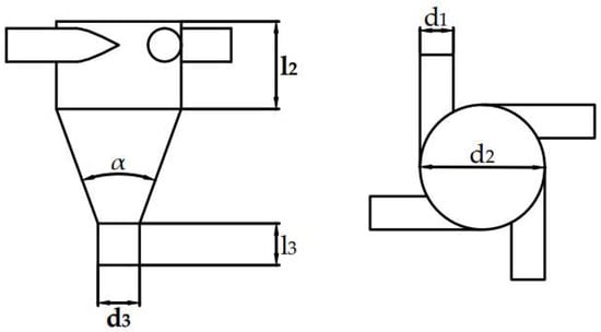
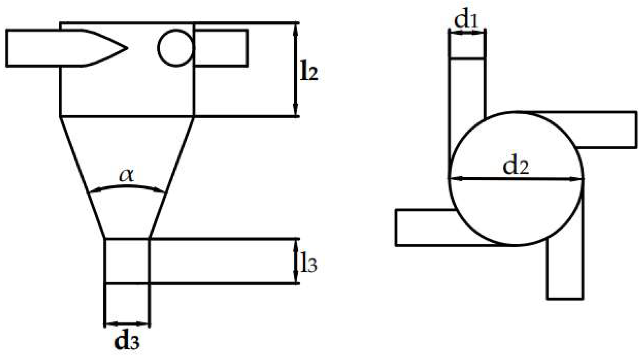
The pressure-swirl nozzle considered in this study is a closed-type hollow-cone configuration composed of four main internal sections, namely the inlet section, swirl chamber, contraction section, and outlet section, as shown in Figure 3. Liquid enters the nozzle through tangential inlet passages distributed around the swirl chamber and develops a strong swirling motion inside the nozzle. Owing to the resulting radial pressure gradient, a low-pressure region is formed near the nozzle axis, which promotes the formation of an air core. After passing through the contraction section, the liquid is discharged through the outlet in the form of an annular liquid film. In the present work, the outlet air-core/liquid-film structure provides the numerical basis for defining the theoretical outlet initial conditions.
Figure 3.
Schematic diagram of the pressure-swirl nozzle and its main structural sections.
The baseline geometric parameters of the nozzle are = 0.48 mm, = 1.80 mm, = 0.60 mm, = 1.26 mm, = 0.60 mm, and = 40°, where , and denote the inlet, swirl-chamber, and outlet diameters, respectively, and and denote the swirl-chamber height and outlet length, respectively. To avoid ambiguity, is used exclusively for the nozzle geometry, whereas denotes the spray cone angle in the following analysis.
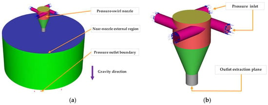
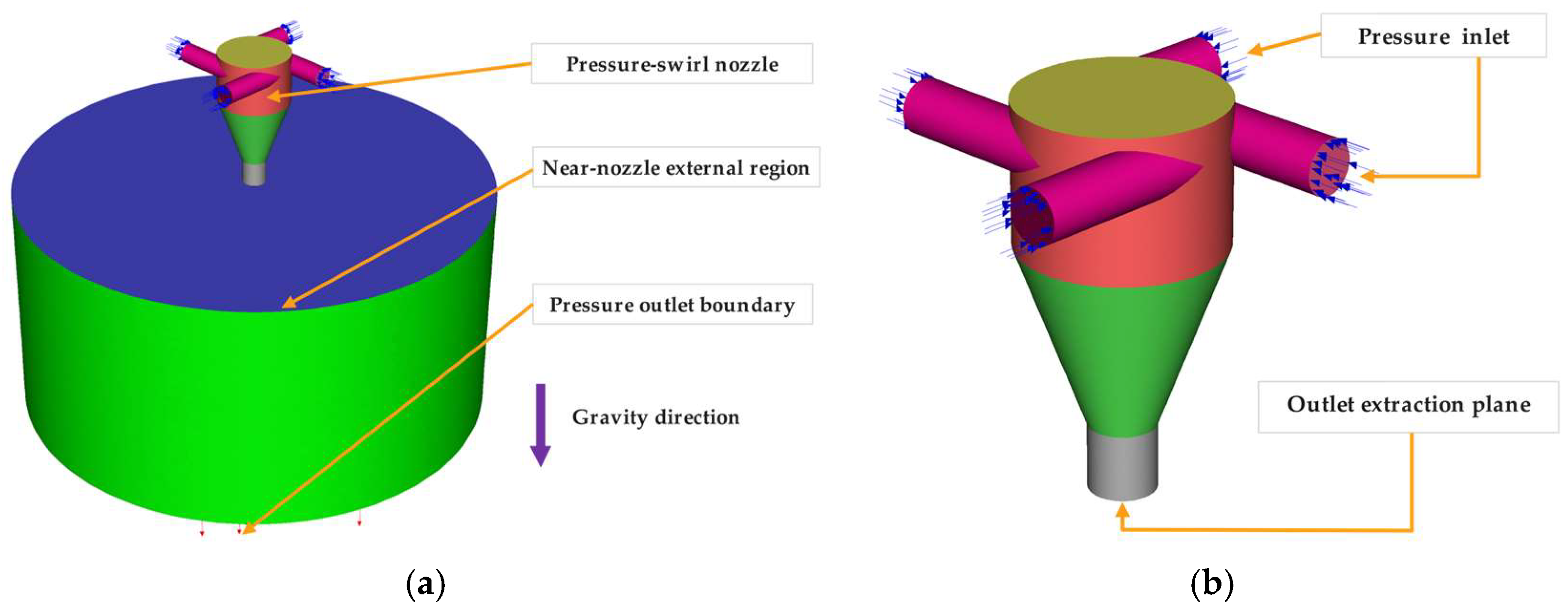
The computational domain includes the internal nozzle region and a near-nozzle external region, as shown in Figure 4. The internal region was used to resolve the tangential inflow, swirl development, gas-core structure, and outlet annular liquid film. The near-nozzle external region was introduced to capture the initial liquid-film contour immediately downstream of the nozzle outlet and to support the extraction of outlet-related quantities. Therefore, the computational domain was designed for the assessment of near-nozzle outlet initial conditions rather than for reconstructing the complete downstream spray breakup and droplet transport process.
Figure 4.
Computational domain and boundary-condition arrangement. (a) Overall computational domain including the pressure-swirl nozzle and the near-nozzle external region; (b) enlarged view of the pressure-swirl nozzle showing the tangential pressure inlets and the outlet extraction plane. The outer boundary of the external domain was defined as a pressure outlet, and gravity was applied along the axial direction. The colored regions distinguish the nozzle body, external computational domain, pressure inlet, pressure outlet boundary, and outlet extraction plane, while the arrows indicate the corresponding boundary locations and gravity direction.
As shown in Figure 4, pressure-inlet boundary conditions were imposed at the tangential inlet passages, and the outer boundary of the external domain was defined as a pressure outlet with zero gauge pressure. No-slip boundary conditions were applied to all solid walls, which were assumed to be hydraulically smooth. Gravitational acceleration was introduced as a body-force term in the momentum equations and was applied along the nozzle axial direction. For the reduced-gravity cases, only the magnitude of gravitational acceleration was varied, while the nozzle geometry, physical models, fluid properties, boundary conditions, and numerical solution settings were kept unchanged. This treatment was adopted to isolate the influence of gravity level on the outlet initial conditions.
The outlet extraction plane marked in Figure 4b was used to evaluate the outlet-related parameters, including the discharge coefficient, outlet liquid-film thickness, and outlet velocity components. The near-nozzle external region was further used to determine the initial spray cone angle from the initial liquid-film contour. These definitions ensure that the CFD-derived outlet quantities are consistent with the variables used in the reduced-order theoretical framework.
3.2. CFD Setup and Grid-Independence Verification
The gas–liquid flow inside the nozzle and in the near-nozzle external region was simulated using ANSYS Fluent 2024 R1. The computational mesh was generated using Fluent Meshing. The Volume of Fluid (VOF) method was employed to capture the immiscible gas–liquid interface [38], and the continuum surface force (CSF) model was used to account for surface-tension effects [39]. The gas–liquid interface was reconstructed using the geometric reconstruction scheme. Water was used as the working liquid, and air was used as the surrounding gas phase. Both phases were treated as incompressible under the present operating conditions. The density and dynamic viscosity of water were set to 998 kg⋅m−3 and 1.0 × 10⁻³ Pa⋅s, respectively, and the surface tension coefficient was set to 0.072 N⋅m−1. This numerical framework was adopted because the present study focuses on the outlet air-core structure, annular liquid-film formation, and near-nozzle liquid-film spreading, rather than on the complete downstream spray breakup and droplet transport process.
Turbulence effects were modeled using the RNG model [40]. This model was selected as a practical compromise between numerical robustness, computational cost, and engineering applicability for the present transient VOF simulations. It is recognized that the RNG model is based on the Boussinesq hypothesis, in which the turbulent viscosity is treated as an isotropic scalar. Therefore, it cannot fully resolve turbulence anisotropy in strongly swirling flows. The Reynolds Stress Model may provide a more detailed description of anisotropic Reynolds stresses; however, the present work focuses mainly on integral outlet quantities, including the discharge coefficient, outlet liquid-film thickness, outlet velocity components, and initial spray cone angle, rather than on the detailed Reynolds-stress distribution inside the nozzle. Considering the number of pressure-drop and gravity-level cases involved in the present assessment, the RNG model was adopted as a computationally efficient turbulence closure. The possible influence of turbulence-model selection is acknowledged as a limitation of the present work.
A pressure-inlet boundary condition was imposed at the tangential inlet passages, and the outer boundary of the near-nozzle external domain was defined as a pressure outlet with zero gauge pressure. No-slip boundary conditions were applied to all solid walls, which were assumed to be hydraulically smooth. Gravity was introduced as a body-force term in the momentum equations and was varied according to the gravity levels considered in the theoretical analysis. For all reduced-gravity cases, the nozzle geometry, physical properties, boundary conditions, and numerical solution schemes were kept unchanged, while only the gravitational acceleration was varied. The pressure drops ranged from 0.1 to 0.5 MPa, and the gravity levels were set to 1 g, 10−1 g, 10−2 g, 10−3 g, 10−4 g, and 10−5 g. This treatment was adopted to isolate the influence of gravity level on the outlet initial conditions.
Pressure–velocity coupling was achieved using the SIMPLE algorithm. The momentum equations were discretized using a second-order upwind scheme, the liquid volume fraction equation was discretized using the geometric reconstruction scheme, and pressure interpolation was performed using the PRESTO! Scheme [41]. The simulations were conducted in a transient manner using an adaptive time-stepping strategy to resolve the unsteady evolution of the gas–liquid interface while maintaining numerical stability. The residual convergence criterion for the governing equations was set to 10−5. During the calculation, the inlet and outlet mass flow rates, together with the main outlet parameters, were monitored. After a statistically quasi-steady state was reached, the outlet quantities were sampled and averaged for subsequent analysis.
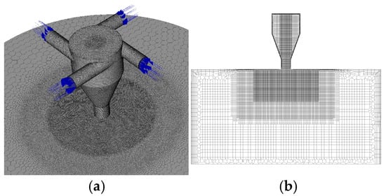
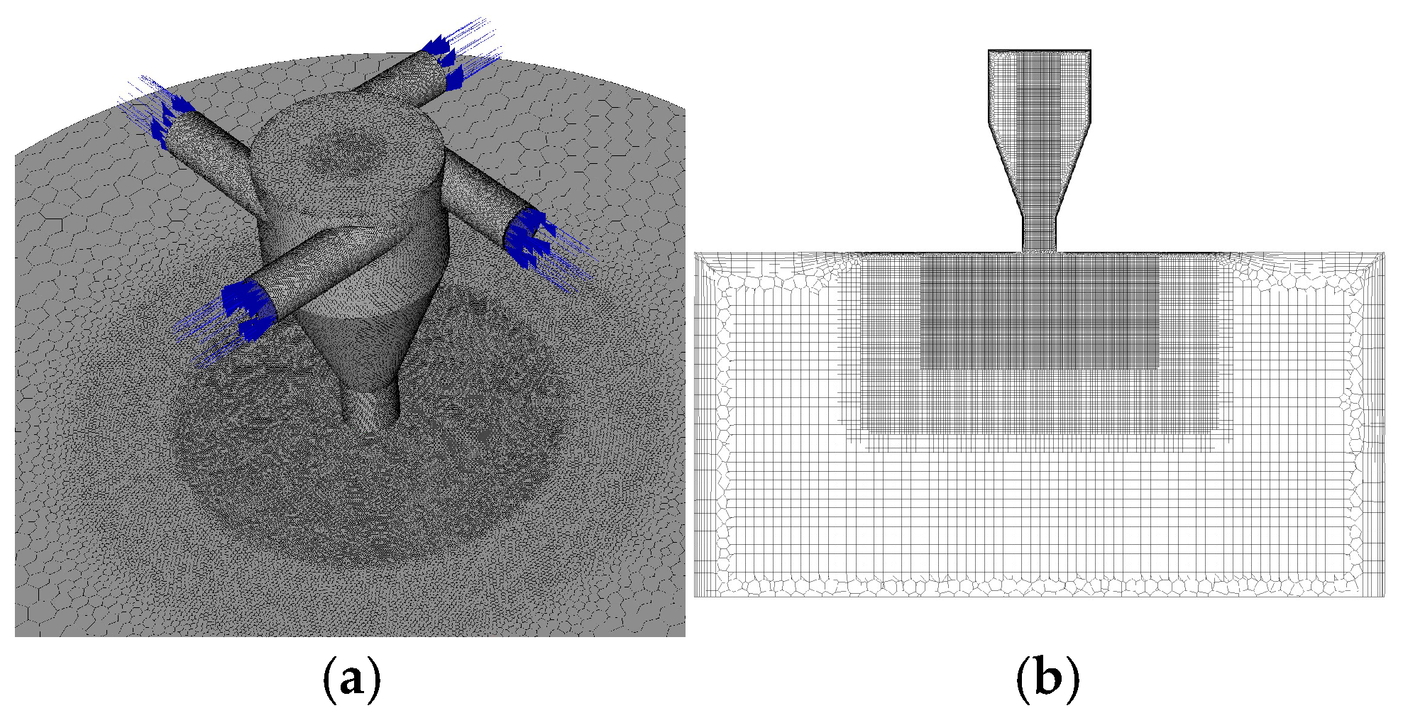
The computational domain was discretized using the poly-hexcore meshing technique implemented in Fluent Meshing. The mesh distribution is shown in Figure 5. Within the poly-hexcore framework, local mesh refinement was applied according to the expected flow characteristics. Body-of-influence (BOI)-based refinement was employed in the tangential inlet passages, swirl chamber, contraction section, outlet region, and near-nozzle external region, where large velocity gradients, strong swirling motion, near-wall effects, and gas–liquid interface deformation were expected. Away from the nozzle exit, the mesh was gradually coarsened to reduce computational cost while maintaining sufficient resolution in the regions relevant to outlet-parameter extraction. Standard wall functions were applied for near-wall treatment, which is consistent with the adopted RNG turbulence model and the hydraulically smooth no-slip wall assumption.
Figure 5.
Mesh distribution of the computational domain. (a) Surface mesh of the pressure-swirl nozzle and near-nozzle external region; (b) mesh distribution on the central cross-section, showing local refinement near the nozzle outlet and near-nozzle region. The blue arrows indicate the inlet flow directions.
Grid-independence verification was performed using a series of meshes with characteristic cell sizes ranging from 0.0010 mm to 0.0040 mm, as summarized in Table 1. The spray cone angle and discharge coefficient were selected as evaluation quantities, and the results obtained with the finest mesh were taken as the reference solution. Based on the grid-independence verification, the mesh with a characteristic size of 0.0030 mm was adopted in the present simulations. This mesh contained approximately 1.98 × 10⁶ cells, and the relative deviations in the spray cone angle and discharge coefficient were 1.22% and 1.44%, respectively, compared with the finest mesh. Since both deviations were within 2%, the selected mesh was considered to provide a reasonable balance between numerical accuracy and computational cost for the present CFD-based assessment of outlet initial conditions.
Table 1.
Grid-independence verification based on spray cone angle and discharge coefficient.
3.3. Outlet-Parameter Extraction and CFD-Based Assessment Procedure
To assess the reduced-order model developed in Section 2, the key outlet initial parameters were extracted from the CFD results using definitions consistent with the theoretical formulation. The quantities considered in the present study include the discharge coefficient Cd, outlet axial velocity , outlet tangential velocity , outlet liquid-film thickness , and initial spray cone angle . These quantities were selected because they jointly characterize the nozzle-exit state from the viewpoints of flow capacity, momentum transport, swirl intensity, liquid-film geometry, and initial near-nozzle spreading.
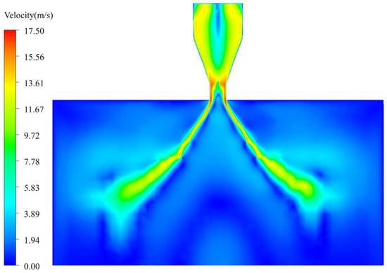
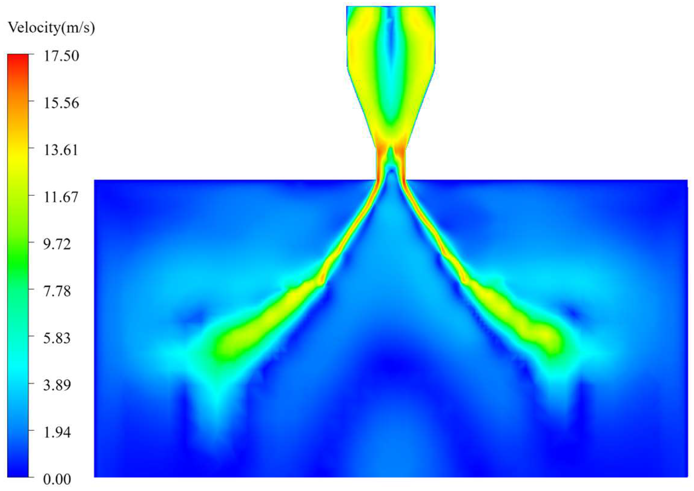
To illustrate the flow-field basis for the extraction of these outlet quantities, Figure 6 presents a representative velocity distribution on the longitudinal section of the flow field. The velocity contour shows the internal swirling flow, the acceleration near the nozzle outlet, and the near-nozzle development of the annular liquid film. This flow-field information provides the numerical basis for extracting the outlet velocity components, liquid-film geometry, and initial spray cone angle used in the reduced-order framework.
Figure 6.
Representative velocity distribution on the longitudinal section of the flow field under = 0.3 MPa and 1 g. The contour illustrates the internal swirling flow, outlet annular liquid film, and near-nozzle flow development used for outlet-parameter extraction.
The discharge coefficient was determined from the actual liquid flow rate through the nozzle outlet. Specifically, the liquid-phase mass flux was integrated over the outlet cross-section, and the corresponding value of was calculated from the pressure drop and outlet area using the same definition as that adopted in the theoretical model. In this way, the CFD-derived discharge coefficient is directly comparable with the discharge coefficient used in the reduced-order formulation.
The outlet axial and tangential velocity components, and , were extracted on the nozzle-exit cross-section by first identifying the liquid region from the local volume-fraction distribution and then averaging the axial and circumferential velocity components within this liquid region. The resulting velocities therefore represent the annular liquid film rather than the central gas core. This treatment ensures consistency with the theoretical outlet initial-condition model, in which the outlet state is described in terms of averaged liquid-film quantities.
The outlet liquid-film thickness was determined from the air-core/liquid-film structure on the outlet cross-section. The air-core diameter was first identified from the gas–liquid interface distribution, and the equivalent outlet liquid-film thickness was then evaluated as one-half of the difference between the outlet diameter and the equivalent air-core diameter.
The initial spray cone angle was obtained from the liquid-film contour in the near-nozzle external region. Here, “initial” refers to the near-nozzle spray angle extracted after the outlet liquid film reached a statistically quasi-steady state, rather than to the instantaneous angle during the start-up transient stage or the fully developed downstream spray cone angle. The gas–liquid interface boundaries on both sides of the liquid film were extracted in the initial spreading zone downstream of the outlet, and linear fitting was applied to determine the included angle between the two fitted boundaries. To reduce the influence of downstream deformation, the fitting was restricted to the near-nozzle region where the liquid film remained continuous.
All outlet quantities were extracted after the flow reached a statistically quasi-steady state. Under normal-gravity conditions, the CFD-extracted discharge coefficient and initial spray cone angle were used to define the baseline outlet descriptors in the reduced-order framework. The corresponding baseline outlet velocity components and subsequent gravity-corrected outlet states were then evaluated using the theoretical formulation. For reduced-gravity cases, the CFD-extracted outlet quantities were used to assess the model-calculated gravity-induced deviations.
Therefore, the comparison between the reduced-order model and CFD results should be interpreted as a CFD-based consistency assessment rather than a fully independent validation. Since the purpose of the present numerical analysis is to assess near-nozzle outlet initial conditions rather than to reconstruct the full downstream spray field, the extraction procedure was restricted to the nozzle-exit section and the immediate near-nozzle region.
4. Results and Discussion
4.1. Pressure-Dependent Baseline Outlet Initial Conditions at Normal Gravity
In the present framework, the baseline outlet state under normal gravity is characterized through a combination of CFD-based descriptor identification and reduced-order reconstruction. Specifically, the discharge coefficient and the initial spray cone angle are treated as baseline outlet descriptors identified from the CFD results, while the corresponding outlet axial and tangential velocity components are reconstructed from the reduced-order relations established in Section 2 using these descriptors. In this way, the baseline nozzle-exit state is represented in a compact form from both the flow capacity and velocity structure perspectives and provides the reference state for the subsequent gravity-corrected analysis.
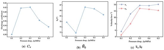
As the pressure drop increases from 0.1 to 0.3 MPa, the discharge coefficient rises markedly from about 0.30 to 0.42, indicating an enhancement of the effective flow-through capability of the nozzle in the low-to-moderate pressure range. When the pressure drop is further increased to 0.4–0.5 MPa, however, decreases to approximately 0.36 and 0.33, respectively. This trend suggests that the baseline flow capacity response is not a simple monotonic amplification with pressure, but rather reflects the combined influence of pressure-driven discharge and the evolving internal swirling structure.
The pressure dependence of the initial spray cone angle also shows a non-monotonic feature. Specifically, decreases from 77.7° at 0.1 MPa to 71.8° at 0.2 MPa, then increases sharply to 85.95° at 0.3 MPa, followed by a moderate reduction to 85.03° and 81.8° at 0.4 and 0.5 MPa, respectively. This indicates that the baseline outlet directionality is pressure-sensitive, but its response is not governed by pressure alone in a linear manner. Instead, the variation in implies that the outlet velocity-direction structure undergoes a redistribution as the operating pressure changes.
Based on the identified values of and , the reconstructed outlet velocity components further reveal how the baseline momentum state evolves with pressure. The axial velocity increases from about 5.7 m/s at 0.1 MPa to about 13.8–14.1 m/s in the range of 0.3–0.5 MPa, showing that pressure remains the primary driving factor for downstream liquid transport. The tangential velocity exhibits a similar increase, from about 4.6 m/s at 0.1 MPa to about 12.9 m/s at 0.3 MPa and then remains at a relatively high level with only a slight decrease at higher pressure drops. This behavior indicates that the residual swirl intensity at the nozzle exit is also strengthened as the pressure rises, although the rate of increase becomes weaker once the pressure exceeds the intermediate range.
Overall, the results in Figure 7 show that the baseline outlet state under normal gravity can be compactly represented by the CFD-identified outlet descriptors and the corresponding reduced-order reconstruction of the outlet velocity components. Under the present sample conditions, pressure mainly determines the characteristic momentum level and directional state of the nozzle-exit liquid film, whereas the non-monotonic variation in and indicates that the baseline outlet response remains intrinsically nonlinear. These baseline results provide the reference state from which the gravity-induced deviations are evaluated in the following sections.
Figure 7.
Pressure-dependent baseline outlet descriptors and model-reconstructed velocity components under normal-gravity conditions: (a) discharge coefficient ; (b) initial spray cone angle ; (c) reconstructed outlet axial and tangential velocity components, and . The symbols represent discrete calculated results, and the connecting lines are used only as visual guides rather than fitted or interpolated functions.
4.2. Gravity-Level Effect on Outlet Initial Conditions Under Forward-Gravity Injection
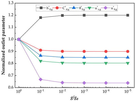
To clarify how the nozzle outlet state varies with gravity level under forward-gravity injection, the corrected outlet parameters are evaluated at a representative pressure drop of 0.3 MPa over six gravity levels from 1 g to 10−5 . Following the gravity-correction framework established in Section 2.4, the gravity-corrected outlet descriptors and reconstructed velocity components are expressed in normalized form relative to their corresponding values at 1 g. The normalized parameter is defined as
where denotes the corresponding outlet parameter at gravity level and is its value under normal gravity, and is the normal-gravity acceleration. The calculated results are shown in Figure 8.
Figure 8.
Gravity-level effect on normalized outlet initial-condition parameters under forward-gravity injection at a representative pressure drop of 0.3 MPa. The superscript asterisk (*) indicates that the variables are normalized.
As shown in Figure 8, all outlet parameters respond most strongly during the transition from 1 g to 10−1 , whereas further reduction in gravity leads to much smaller incremental changes. This behavior indicates that the principal gravity-induced adjustment of the outlet state occurs in the higher part of the reduced-gravity range, while the response gradually approaches a plateau as the gravity level decreases further. Under the present model formulation and sample conditions, reduced gravity therefore acts as a finite correction to the baseline outlet state rather than producing a continuously amplified response over the entire range considered.
The reconstructed axial and tangential velocity components both decrease as the gravity level is reduced, but their sensitivities are clearly different. The normalized axial velocity shows a moderate decrease and then rapidly approaches a nearly constant level, indicating that the bulk axial transport capacity of the outlet liquid film is weakened under reduced gravity, although the magnitude of this response remains limited. By contrast, the normalized tangential velocity decreases more markedly, especially between 1 g and 10−1 , and remains substantially below its normal-gravity value thereafter. This result suggests that the swirl-related component of the outlet state is more sensitive to gravity variation than the axial component.
A different trend is observed for the outlet liquid-film thickness. As the gravity level decreases, the normalized thickness increases and then gradually stabilizes. This indicates that, within the present formulation, reduced gravity tends to produce a thicker outlet liquid film at the nozzle exit. At the same time, both the corrected discharge coefficient and the normalized initial spray cone angle decrease with decreasing gravity level and then remain close to stable plateau values. Taken together, these results indicate that reduced gravity weakens the flow-through capability and initial spreading tendency of the liquid film while simultaneously increasing its outlet thickness.
Overall, the results in Figure 8 show that gravity reduction under forward-gravity injection leads to a coordinated modification of the outlet initial conditions. In the present model, decreasing gravity reduces the axial and tangential velocity components, decreases the discharge coefficient and initial spray cone angle, and increases the outlet liquid-film thickness. Among these parameters, the tangential velocity exhibits the strongest response, whereas the axial velocity changes more moderately. This difference suggests that gravity affects the swirl-related and geometric aspects of the outlet state more strongly than the bulk axial transport level.
4.3. Pressure Modulation of Gravity-Induced Variations Under Forward-Gravity Injection
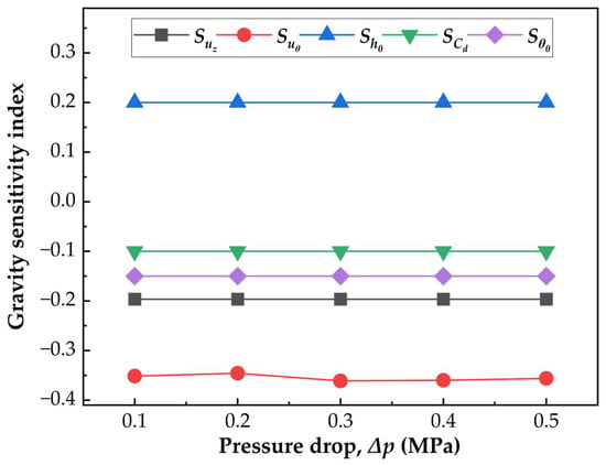
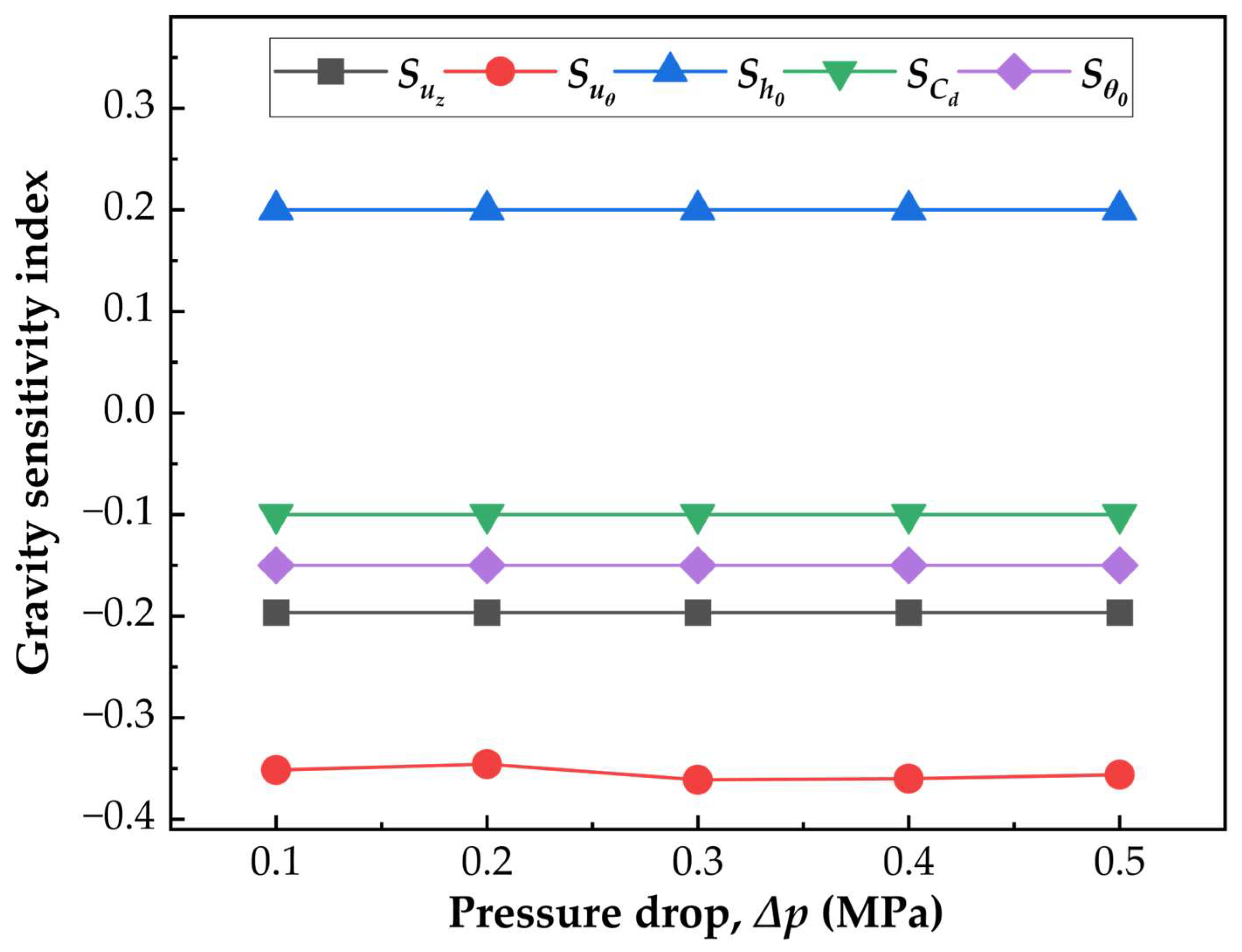
Beyond the representative-pressure analysis in Section 4.2, it is also necessary to determine whether the magnitude of the gravity-induced correction is itself pressure-dependent under forward-gravity injection. For this purpose, a gravity sensitivity index is introduced to quantify the relative variation in each outlet parameter between normal gravity and the lowest gravity level considered, i.e.,
where represents the corresponding outlet parameter. The calculated results for different pressure drops are shown in Figure 9.
Figure 9.
Pressure modulation of gravity-induced variations in outlet initial-condition parameters under forward-gravity injection.
Figure 9 shows that, within the present constant-coefficient correction framework, the pressure dependence of gravity sensitivity remains weak over the range considered. For most quantities, the sensitivity curves remain nearly horizontal, indicating that the relative magnitude of the gravity-induced correction changes little as the pressure drop increases from 0.1 to 0.5 MPa. Under the present formulation and sample conditions, pressure mainly determines the baseline outlet level, whereas its influence on the strength of the gravity response remains limited.
Among the five parameters, the tangential velocity exhibits the largest sensitivity magnitude. The index remains negative over the entire pressure range and its absolute value is consistently greater than that of the other sensitivity indices. This indicates that the swirl-related outlet component is the most responsive to gravity variation in the present model. By comparison, the axial velocity also shows a negative sensitivity, but its magnitude is distinctly smaller, suggesting that the axial transport component is less affected by the same change in gravity level. The corrected discharge coefficient and the initial spray cone angle likewise remain negative, indicating a systematic reduction in flow capacity and initial spreading tendency as gravity is reduced.
The outlet liquid-film thickness shows the opposite behavior. The sensitivity index is positive and remains nearly constant with pressure, indicating that reduced gravity tends to increase the outlet liquid-film thickness and that this tendency is only weakly pressure-dependent. The approximately pressure-independent behavior of , together with the similar behavior of and , implies that the gravity-induced modification of outlet descriptors is governed primarily by the correction form itself rather than by strong pressure amplification within the present parameter range. Only shows a modest fluctuation with pressure, but, even so, the overall variation remains limited.
Taken together, the results suggest that, within the present correction framework, the pressure effect on gravity sensitivity is secondary compared with its role in setting the baseline outlet state. Under forward-gravity injection, reduced gravity tends to weaken the axial and tangential velocity components, the discharge coefficient, and the initial spray cone angle, while increasing the outlet liquid-film thickness. The relative magnitude of these responses changes only slightly with pressure, suggesting that the gravity-induced deviation from the baseline state remains relatively stable over the operating range considered here.
4.4. CFD-Based Consistency Assessment Under Forward-Gravity Conditions
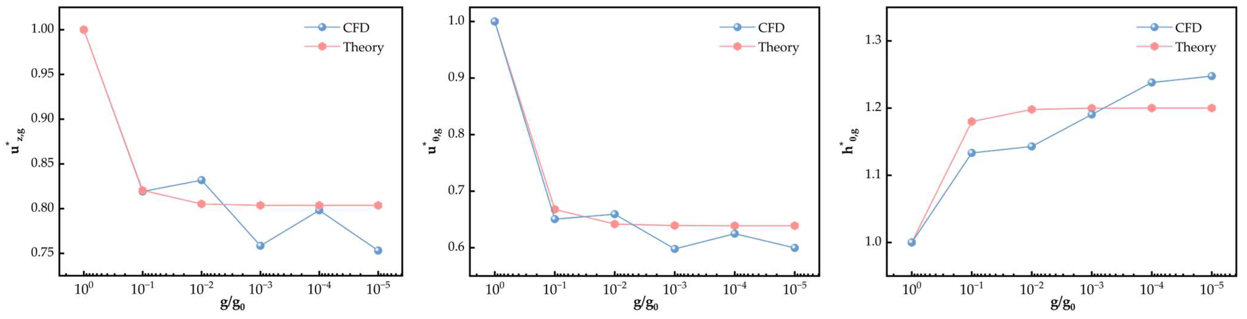
To assess the first-order consistency between the reduced-order model and the CFD results under forward-gravity conditions, the outlet parameters calculated from the gravity-corrected framework established in Section 2 were compared with the corresponding CFD-extracted quantities at the representative pressure drop of 0.3 MPa over six gravity levels, with ranging from 1 to 10−5. In this comparison, the model calculations were carried out from the baseline outlet state defined under normal gravity together with the parametric gravity-correction relations introduced in Section 2.4. The comparison focuses on three outlet initial-condition parameters, namely the axial velocity , tangential velocity , and outlet liquid-film thickness . These quantities jointly characterize the outlet transport level, residual swirl intensity, and outlet geometric state, and therefore provide a concise basis for assessing the consistency between the reduced-order model and the CFD-extracted outlet quantities. For consistency with the normalization introduced in Section 4.2, all compared quantities are expressed relative to their corresponding values at 1 g.
Figure 10 shows that the model-calculated results and CFD-extracted results follow the same overall response to gravity reduction. As the gravity level decreases, both and decline, whereas increases. This indicates that the reduced-order framework captures the primary direction of the gravity-induced variation in the outlet state under forward-gravity injection. The decrease in is more pronounced than that in , indicating that the swirl-related outlet component remains more sensitive to gravity variation than the axial transport component. The liquid-film thickness exhibits the opposite response, increasing as gravity is reduced; this trend is also represented by the reduced-order model.
Figure 10.
Comparison between theoretical predictions and CFD results for the normalized outlet initial-condition parameters under forward-gravity injection at a representative pressure drop of 0.3 MPa. The superscript asterisk (*) denotes the normalized value.
The relative error is defined as
The quantitative comparison between the reduced-order model and CFD results is summarized in Table 2. Using this measure, the relative error of lies between 0.15% and 6.71%, that of lies between 2.26% and 6.92%, and that of lies between 0.78% and 4.83%. These values show that the agreement between the theoretical predictions and CFD results is generally satisfactory for all three parameters. The axial velocity is reproduced with particularly small deviation at 10−1 and 10−4 , while somewhat larger differences appear at 10−3 and 10−5 . For the tangential velocity, the agreement remains stable over the full gravity range, with the error consistently within a moderate level. For the liquid-film thickness, the model captures the increasing tendency well, although the deviation is slightly larger at 10−1 and 10−2 than at lower gravity levels.
Table 2.
Relative errors between theoretical predictions and CFD results for the normalized outlet initial-condition parameters under forward-gravity injection at a representative pressure drop of 0.3 MPa.
The remaining discrepancies are attributable to the simplified character of the present formulation. In the reduced-order model, gravity affects the outlet state through parametric corrections to a limited set of baseline outlet descriptors, whereas the CFD solution retains local interface deformation, outlet non-uniformity, and the detailed redistribution of the internal gas-core/liquid-film structure near the nozzle exit. Under these conditions, some mismatch in local response amplitude is expected. Nevertheless, the present framework captures the first-order direction and overall magnitude of the gravity-induced variation within the investigated conditions. Therefore, the comparison should be interpreted as a CFD-based consistency assessment rather than a fully independent validation. The framework provides a practical first-order route for linking the CFD-informed 1 g baseline outlet state to its reduced-gravity deviation and for interpreting how gravity modifies the nozzle-exit condition under forward-gravity injection.
5. Conclusions
A reduced-order framework was developed to describe the outlet initial conditions of a pressure-swirl nozzle under reduced-gravity conditions. The analysis was organized around a CFD-informed baseline outlet state under normal gravity and its subsequent gravity-induced deviation, allowing the respective roles of operating pressure and gravity level to be examined within a unified description of outlet transport, swirl intensity, and liquid-film geometry.
The results indicate that operating pressure primarily determines the baseline outlet state, whereas reduced gravity acts mainly as a correction to this baseline rather than as a mechanism that fundamentally reconstructs the outlet flow. Under forward-gravity injection, decreasing gravity leads to reductions in the axial velocity component, tangential velocity component, discharge coefficient, and initial spray cone angle, while the outlet liquid-film thickness increases. Among these quantities, the tangential velocity exhibits the strongest response, suggesting that swirl-related outlet behavior is more sensitive to gravity variation than the bulk axial transport level under the present conditions.
Within the present constant-coefficient correction framework and over the range considered here, the modulation of gravity sensitivity by pressure remains limited. Although the baseline levels of the outlet parameters vary substantially with pressure, the relative magnitude of the gravity-induced correction changes only slightly, indicating that pressure mainly sets the outlet state while its influence on the strength of the gravity response remains secondary under the present formulation.
The proposed formulation was further assessed by comparison with CFD results for representative reduced-gravity cases. When evaluated in normalized form relative to the corresponding 1 g baseline, the relative error ranges are 0.15–6.71% for the axial velocity, 2.26–6.92% for the tangential velocity, and 0.78–4.83% for the outlet liquid-film thickness. This CFD-based comparison indicates that the framework can capture the first-order direction and magnitude of the gravity-induced variation in the outlet initial conditions within the investigated conditions. The remaining deviations suggest that the current formulation still compresses the detailed redistribution of the gas-core/liquid-film structure near the nozzle exit into a limited set of correction terms.
Overall, the present study provides a compact and physically interpretable framework for linking reduced-gravity effects to nozzle outlet initial conditions. The present comparison should be interpreted as a CFD-based consistency assessment rather than a fully independent validation. Independent experimental validation is not included in the present study and remains necessary in future work to confirm the quantitative predictive capability of the proposed framework, especially under reduced-gravity conditions. In addition, the present study is limited to one nozzle geometry and focuses on near-nozzle outlet initial conditions rather than the complete downstream spray breakup and droplet transport process. Further refinement is also needed in the treatment of outlet geometric response and local flow redistribution before the model can be extended to broader operating conditions.
Author Contributions
Conceptualization, H.W., X.Z. and H.Z.; methodology, H.W., X.Z. and H.Z.; validation, H.W.; formal analysis, H.W.; investigation, H.W.; resources, H.Z.; data curation, H.W., P.Z. and Y.F.; writing—original draft preparation, H.W.; writing—review and editing, X.Z., X.Y. and H.Z.; visualization, H.W.; supervision, H.Z.; project administration, H.Z.; Funding acquisition, H.Z. All authors have read and agreed to the published version of the manuscript.
Funding
This work was supported by the National Key R&D Program of China (Grant No. 2021YFA0716204).
Data Availability Statement
The data presented in this study are available on reasonable request from the corresponding author due to data confidentiality restrictions.
Conflicts of Interest
The authors declare no conflicts of interest.
Abbreviations
The following abbreviations are used in this manuscript:
| CFD | Computational Fluid Dynamics |
| CSF | Continuous Surface Force |
| CSES | Combustion Science Experimental System |
| CSS | China Space Station |
| RNG | Renormalization Group (RNG k–ε model) |
| SIMPLE | Semi-Implicit Method for Pressure-Linked Equations |
| PRESTO! | Pressure Staggering Option |
| VOF | Volume of Fluid |
References
- Zhao, P.; Zhang, X.; Fang, Y.; Wu, H.; Yang, X.; Zheng, H. On-Orbit Functional Verification of Combustion Science Experimental System in China Space Station. Aerospace 2025, 12, 448. [Google Scholar] [CrossRef] [Scilit]
- Zhenzhong, Z.; Wenjun, K.; Hualiang, Z. Design of Combustion Science Experimental System for China Space Station. Chin. J. Space Sci. 2022, 40, 72–78. [Google Scholar] [CrossRef] [Scilit]
- Xiaowu, Z.; Huilong, Z.; Kun, W.; Xiaofang, Y. Combustion Chamber Design and Analysis of the Space Station Combustion Science Experimental System. Chin. J. Space Sci. 2022, 41, 301–309. [Google Scholar] [CrossRef] [Scilit]
- Wen, Y.; Li, L.; Li, X.; Luo, L.; Chen, T.; Zhang, W.; Zhou, H.; Chen, S.; Sun, Y.; Shi, J.; et al. Extinction of Microgravity Partially Premixed Flame Aboard the Chinese Space Station. Proc. Combust. Inst. 2024, 40, 105574. [Google Scholar] [CrossRef] [Scilit]
- Zhu, F.; Li, D.; Wang, S.; Yi, H. Shape and Sooting Characteristics of Methane Laminar-Jet Diffusion Flames in Microgravity. Chin. J. Space Sci. 2026, 46, 121–130. [Google Scholar] [CrossRef] [Scilit]
- Dietrich, D.L.; Nayagam, V.; Hicks, M.C.; Ferkul, P.V.; Dryer, F.L.; Farouk, T.; Shaw, B.D.; Suh, H.K.; Choi, M.Y.; Liu, Y.C.; et al. Droplet Combustion Experiments Aboard the International Space Station. Microgravity Sci. Technol. 2014, 26, 65–76. [Google Scholar] [CrossRef] [Scilit]
- Suñol, F.; González-Cinca, R. Liquid Jet Breakup and Subsequent Droplet Dynamics under Normal Gravity and in Microgravity Conditions. Phys. Fluids 2015, 27, 77102. [Google Scholar] [CrossRef] [Scilit]
- Umemura, A. Self-Destabilizing Mechanism of a Laminar Inviscid Liquid Jet Issuing from a Circular Nozzle. Phys. Rev. E 2011, 83, 46307. [Google Scholar] [CrossRef] [Scilit] [PubMed]
- Thimothée, R.; Chauveau, C.; Halter, F.; Nicoli, C.; Haldenwang, P.; Denet, B. Microgravity Experiments and Numerical Studies on Ethanol/Air Spray Flames. C. R. Méc. 2016, 345, 99–116. [Google Scholar] [CrossRef] [Scilit]
- Kang, Z.; Wang, Z.; Li, Q.; Cheng, P. Review on Pressure Swirl Injector in Liquid Rocket Engine. Acta Astronaut. 2018, 145, 174–198. [Google Scholar] [CrossRef] [Scilit]
- Santolaya, J.L.; Aísa, L.A.; Calvo, E.; García, I.; Cerecedo, L.M. Experimental Study of Near-Field Flow Structure in Hollow Cone Pressure Swirl Sprays. J. Propuls. Power 2007, 23, 382–389. [Google Scholar] [CrossRef] [Scilit]
- Vankeswaram, S.K.; Maly, M.; Jedelsky, J. Understanding the Fuel Spray Characteristics in the Near-Nozzle Region for a Pressure Swirl Atomizer. J. Aerosol Sci. 2024, 178, 106350. [Google Scholar] [CrossRef] [Scilit]
- Higuera, F.J.; Pereña, A. Quasi-Cylindrical Approximation to the Swirling Flow in an Atomizer Chamber. J. Fluid Mech. 2014, 758, 603–620. [Google Scholar] [CrossRef] [Scilit]
- Laurila, E.; Koivisto, S.; Kankkunen, A.; Saari, K.; Maakala, V.; Järvinen, M.; Vuorinen, V. Computational and Experimental Investigation of a Swirl Nozzle for Viscous Fluids. Int. J. Multiph. Flow 2020, 128, 103278. [Google Scholar] [CrossRef] [Scilit]
- Cui, J.; Lai, H.; Li, J.; Ma, Y. Visualization of Internal Flow and the Effect of Orifice Geometry on the Characteristics of Spray and Flow Field in Pressure-Swirl Atomizers. Appl. Therm. Eng. 2017, 127, 812–822. [Google Scholar] [CrossRef] [Scilit]
- Vijay, G.A.; Moorthi, N.S.V.; Manivannan, A. Internal and External Flow Characteristics of Swirl Atomizers: A Review. At. Sprays 2015, 25, 153–188. [Google Scholar] [CrossRef] [Scilit]
- Suyari, M.; Lefebvre, A.H. Film Thickness Measurements in a Simplex Swirl Atomizer. J. Propuls. Power 1986, 2, 528–533. [Google Scholar] [CrossRef] [Scilit] [PubMed]
- Schmidt, D.P.; Nouar, I.; Senecal, P.K.; Rutland, C.J.; Martin, J.K.; Reitz, R.D.; Hoffman, J.A. Pressure-Swirl Atomization in the Near Field; SAE International: Warrendale, PA, USA, 1999. [Google Scholar] [CrossRef] [Scilit]
- Amini, G. Liquid Flow in a Simplex Swirl Nozzle. Int. J. Multiph. Flow 2016, 79, 225–235. [Google Scholar] [CrossRef] [Scilit]
- Ronceros, J.; Raymundo, C.; Ayala, E.; Rivera, D.; Vinces, L.; Ronceros, G.; Zapata, G. Study of Internal Flow in Open-End and Closed Pressure-Swirl Atomizers with Variation of Geometrical Parameters. Aerospace 2023, 10, 930. [Google Scholar] [CrossRef] [Scilit]
- Qian, W.; Wang, J.; Hui, X.; Yang, S.; Cheng, R.; Wang, P. An Improved Comprehensive Atomization Model for Pressure Swirl Atomizers. Aerospace 2024, 11, 658. [Google Scholar] [CrossRef] [Scilit]
- Liu, Z.; Huang, Y.; Sun, L. Studies on Air Core Size in a Simplex Pressure-Swirl Atomizer. Int. J. Hydrog. Energy 2017, 42, 18649–18657. [Google Scholar] [CrossRef] [Scilit]
- Laurila, E.; Roenby, J.; Maakala, V.; Peltonen, P.; Kahila, H.; Vuorinen, V. Analysis of Viscous Fluid Flow in a Pressure-Swirl Atomizer Using Large-Eddy Simulation. Int. J. Multiph. Flow 2019, 113, 371–388. [Google Scholar] [CrossRef] [Scilit]
- Belhadef, A.; Vallet, A.; Amielh, M.; Anselmet, F. Pressure-Swirl Atomization: Modeling and Experimental Approaches. Int. J. Multiph. Flow 2012, 39, 13–20. [Google Scholar] [CrossRef] [Scilit]
- Antipas, G.S.E. Liquid Column Deformation and Particle Size Distribution in Gas Atomization. Int. J. Comput. Mater. Sci. Surf. Eng. 2011, 2, 87–96. [Google Scholar] [CrossRef]
- Dumouchel, C. On the Experimental Investigation on Primary Atomization of Liquid Streams. Exp. Fluids 2008, 45, 371–422. [Google Scholar] [CrossRef] [Scilit]
- Bang, B.-H.; Ahn, C.-S.; Yoon, S.S.; Yarin, A.L. Breakup of Swirling Films Issued from a Pressure-Swirl Atomizer. Fuel 2023, 332, 125847. [Google Scholar] [CrossRef] [Scilit]
- Datta, A.; Som, S.K. Numerical Prediction of Air Core Diameter, Coefficient of Discharge and Spray Cone Angle of a Swirl Spray Pressure Nozzle. Int. J. Heat Fluid Flow 2000, 21, 412–419. [Google Scholar] [CrossRef] [Scilit]
- Liu, J.; Feng, X.; Liang, H.; Zhang, W.; Hui, Y.; Xu, H.; Yang, C. Prediction of Atomization Characteristics of Pressure Swirl Nozzle with Different Structures. Chin. J. Chem. Eng. 2023, 63, 171–184. [Google Scholar] [CrossRef] [Scilit]
- Ronceros, J.; Raymundo, C.; Zapata, G.; Namay, W.; Ronceros, G. Comprehensive Theoretical Formulation and Numerical Simulation of the Internal Flow in Pressure-Swirl Atomizers Type Screw-Conveyer. Energies 2024, 17, 5414. [Google Scholar] [CrossRef] [Scilit]
- Bang, B.-H.; Kim, Y.-I.; Ahn, C.-S.; Jeong, S.; Yoon, Y.; An, S.; Yoon, S.S.; Yarin, A.L. Theoretical Model of Swirling Thick Film Flow inside Converging Nozzles of Various Geometries. Fuel 2020, 280, 118215. [Google Scholar] [CrossRef] [Scilit]
- Amini, G.; Ihme, M.; Dolatabadi, A. Effect of Gravity on Capillary Instability of Liquid Jets. Phys. Rev. E 2013, 87, 53017. [Google Scholar] [CrossRef] [Scilit] [PubMed]
- Ibrahim, A.A.; Jog, M.A. Nonlinear Breakup Model for a Liquid Sheet Emanating from a Pressure-Swirl Atomizer. J. Eng. Gas Turbines Power 2007, 129, 945–953. [Google Scholar] [CrossRef] [Scilit]
- Liu, C.; Liu, F.; Yang, J.; Mu, Y.; Hu, C.; Xu, G. Experimental Investigations of Spray Generated by a Pressure Swirl Atomizer. J. Energy Inst. 2019, 92, 210–221. [Google Scholar] [CrossRef] [Scilit]
- Maly, M.; Sapik, M.; Cejpek, O.; Wigley, G.; Katolicky, J.; Jedelsky, J. Effect of Spill Orifice Geometry on Spray and Control Characteristics of Spill-Return Pressure-Swirl Atomizers. Exp. Therm. Fluid Sci. 2019, 106, 159–170. [Google Scholar] [CrossRef] [Scilit]
- Maly, M.; Cejpek, O.; Sapik, M.; Ondracek, V.; Wigley, G.; Jedelsky, J. Internal Flow Dynamics of Spill-Return Pressure-Swirl Atomizers. Exp. Therm. Fluid Sci. 2021, 120, 110210. [Google Scholar] [CrossRef] [Scilit]
- Wang, K.; Fan, X.; Liu, F.; Liu, C.; Lu, H.; Xu, G. Experimental Studies on Fuel Spray Characteristics of Pressure-Swirl Atomizer and Air-Blast Atomizer. J. Therm. Sci. 2021, 30, 729–741. [Google Scholar] [CrossRef] [Scilit]
- Hirt, C.W.; Nichols, B.D. Volume of Fluid (VOF) Method for the Dynamics of Free Boundaries. J. Comput. Phys. 1981, 39, 201–225. [Google Scholar] [CrossRef] [Scilit]
- Brackbill, J.U.; Kothe, D.B.; Zemach, C. A Continuum Method for Modeling Surface Tension. J. Comput. Phys. 1992, 100, 335–354. [Google Scholar] [CrossRef] [Scilit]
- Yakhot, V.; Orszag, S.A.; Thangam, S.; Gatski, T.B.; Speziale, C.G. Development of Turbulence Models for Shear Flows by a Double Expansion Technique. Phys. Fluids A 1992, 4, 1511–1520. [Google Scholar] [CrossRef] [Scilit]
- Rider, W.J.; Kothe, D.B. Reconstructing Volume Tracking. J. Comput. Phys. 1998, 141, 112–152. [Google Scholar] [CrossRef] [Scilit]

Disclaimer/Publisher’s Note: The statements, opinions and data contained in all publications are solely those of the individual author(s) and contributor(s) and not of MDPI and/or the editor(s). MDPI and/or the editor(s) disclaim responsibility for any injury to people or property resulting from any ideas, methods, instructions or products referred to in the content. |
© 2026 by the authors. Licensee MDPI, Basel, Switzerland. This article is an open access article distributed under the terms and conditions of the Creative Commons Attribution (CC BY) license.