


Abstract
This study investigates the influence of inside-trapped water and remedial grouting on the vertical bearing behaviour of suction bucket foundations in sand through 1 g laboratory model tests. The tests were designed to compare the relative responses of different trapped-water and grouting conditions under the same model scale, sand preparation procedure, and loading protocol. Two target trapped-water conditions were considered: a condition without an observable continuous water layer beneath the bucket lid and a condition with an initial trapped-water thickness of approximately 2 cm. These conditions were controlled and verified before loading using the scale attached to the transparent bucket wall and the underwater camera monitoring system. The results show that inside-trapped water modifies the vertical load-transfer path between the bucket lid and the internal soil plug. When a water layer exists beneath the lid, direct lid–soil plug contact is weakened, and the foundation resistance relies more strongly on skirt-side resistance and the resistance mobilized near the bucket rim. Under cyclic vertical loading, the trapped-water case exhibited larger cumulative displacement and a lower post-cyclic bearing response than the no-trapped-water case. The secant cyclic stiffness showed a continuous increase in the no-trapped-water case, whereas a rise-then-fall trend was observed in the trapped-water case, which may be associated with cyclic densification, soil plug disturbance, changes in lid–soil plug contact, and possible local pore pressure development. Remedial grouting filled the trapped-water space beneath the bucket lid and partially restored the lid–soil plug load-transfer path. Under the present model test conditions, the post-cyclic dimensionless bearing capacity of the grouted cases increased by approximately 13–16% relative to the ungrouted trapped-water case. The grouting cases with different bentonite contents showed similar recovery trends within the limited dataset, suggesting that the improvement was mainly related to filling and sealing the trapped-water space rather than to the intrinsic strength of the grout material.
1. Introduction
With the advancement of offshore wind technology, suction bucket foundations have attracted extensive attention owing to their favourable constructability and high bearing capacity. However, marine soil conditions are often complex, and the formation of inside-trapped water around such foundations can substantially degrade vertical bearing capacity and cyclic performance. This phenomenon has been indirectly observed in studies on the cyclic loading behaviour of suction buckets [1,2]. To address this issue, remedial grouting has become a research focus in recent years. By filling voids induced by inside-trapped water, grouting restores the load-transfer path between the soil and foundation, thereby improving foundation performance. This mechanism is consistent with the conclusion of Da Silva Pereira et al. [3], who emphasized the necessity of grouting for suction buckets under vertical cyclic loading to tackle gaps caused by trapped water.
Research on the installation of suction bucket foundations has become relatively mature. Previous studies have clarified the suction penetration mechanism and verified that suction magnitude is governed by soil effective stress; excessive suction can cause soil failure. This conclusion has been validated by experimental studies on hybrid and composite bucket foundations in silty clay and silty sand [4,5]. Several methods for estimating allowable suction, including the dimensionless suction number and finite-element analysis, have been developed to predict the maximum penetration depth, among which finite-element modelling has been widely adopted in recent years. For instance, Nielsen [6] used this method to analyze the tensile capacity of suction buckets in cohesionless soil. Studies also indicate that the influence of suction on the seepage behaviour of bucket foundations is complex and depends on factors such as the ratio of internal to external permeability coefficients and the effective unit weight of the soil. Related model tests on suction buckets in sandy soil have provided experimental support for this conclusion [7]. In addition, prototype tests on the penetration and re-penetration of multi-bucket foundations have further supplemented the understanding of installation-related behaviours [8], while numerical and experimental studies on tensile and pullout performance during installation have enriched research on suction-controlled penetration [9,10]. Hirai [11] also confirmed the complexity of seepage and bearing interaction through three-dimensional displacement analysis of bucket foundations in sand.
Extensive research has been conducted on the bearing behaviour of suction bucket foundations. For single-bucket foundations, vertical capacity is mainly derived from sidewall friction and base resistance, and is affected by wall–soil contact roughness, length-to-diameter ratio, and soil strength profile. Finite-element studies on suction buckets in cohesionless soils further confirm that installation quality and length-to-diameter ratio significantly affect both the bearing capacity and failure mode of suction bucket foundations [6,12]. Cerfontaine et al. [1] conducted numerical modelling of transient cyclic vertical loading on suction buckets in sand, providing key insights into the mechanism of cyclic bearing degradation. Bienen et al. [2] further investigated the vertical cyclic tensile behaviour of suction buckets in dense sand, complementing the understanding of cyclic performance. Experimental investigations by Lee et al. [13] on the vertical pullout cyclic response of bucket foundations in sand have verified the influence of cyclic loading on bearing characteristics. Barari et al. [12] and Haddad et al. [14] focused on the effect of embedment depth on vertical capacity in loose and cohesionless sands, respectively, highlighting the importance of installation depth. Gao et al. [15] provided experimental evidence for the uplift resistance of suction buckets in sand, supplementing research on vertical bearing capacity. Shonberg et al. [16] presented in situ observation data of suction bucket jackets, offering practical insights into the engineering application and performance optimization of suction bucket foundations.
In this study, a series of laboratory model tests were performed to investigate the influences of inside-trapped water on the monotonic and cyclic bearing capacities of bucket foundations, and the repair effectiveness of several grouting materials and their ability to restore or enhance foundation performance were evaluated. The results provide experimental evidence and practical guidance for the design and optimization of offshore wind turbine foundations.
2. Experiments
2.1. Experiment Model and Experimental Modelling Approach
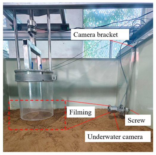
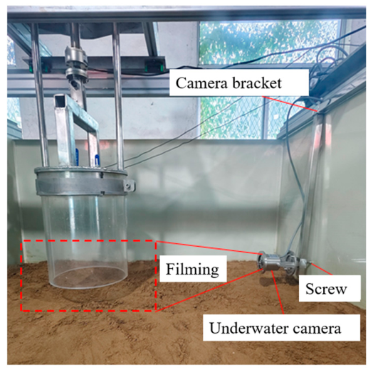
In this study, 1 g laboratory model tests were conducted to investigate the influence of inside-trapped water and remedial grouting on the vertical bearing behaviour of suction bucket foundations in sand. The experimental system consisted of five main components: the model box, the transparent suction bucket model, the vertical loading system, the grouting system, and the underwater monitoring system. The model box provided the saturated sand bed and water boundary condition; the transparent suction bucket model simulated the foundation and allowed the internal soil plug and water layer to be observed; the vertical loading system applied monotonic and cyclic vertical loads; the grouting system delivered slurry into the trapped-water region beneath the bucket lid; and the underwater monitoring system recorded the evolution of the soil plug, trapped-water layer, and local contact condition during penetration, loading, and grouting.
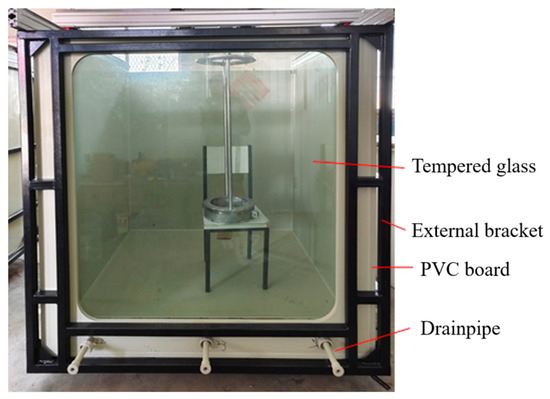
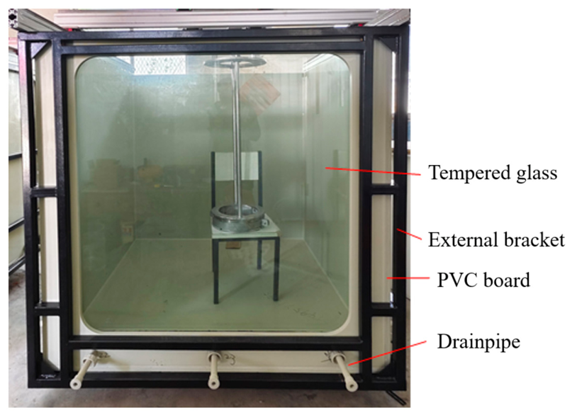
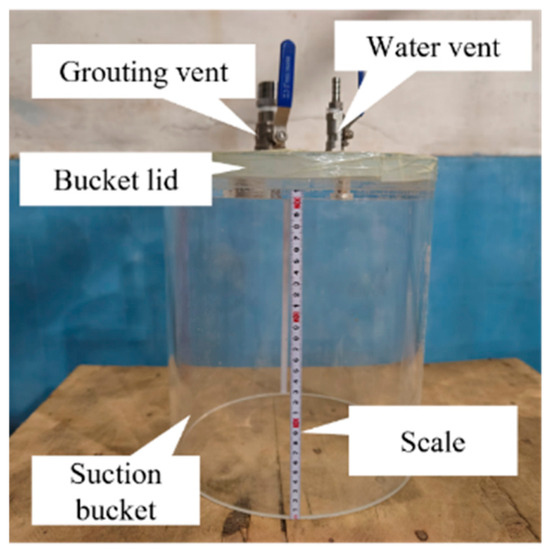
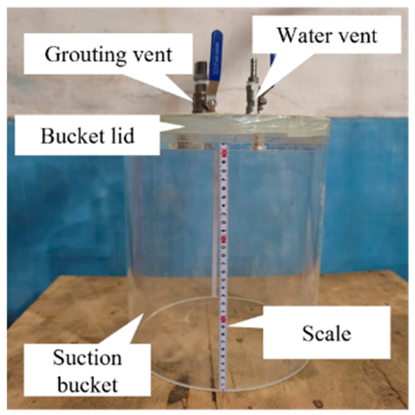
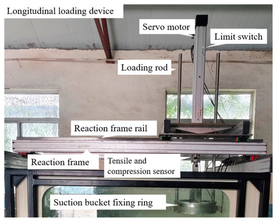
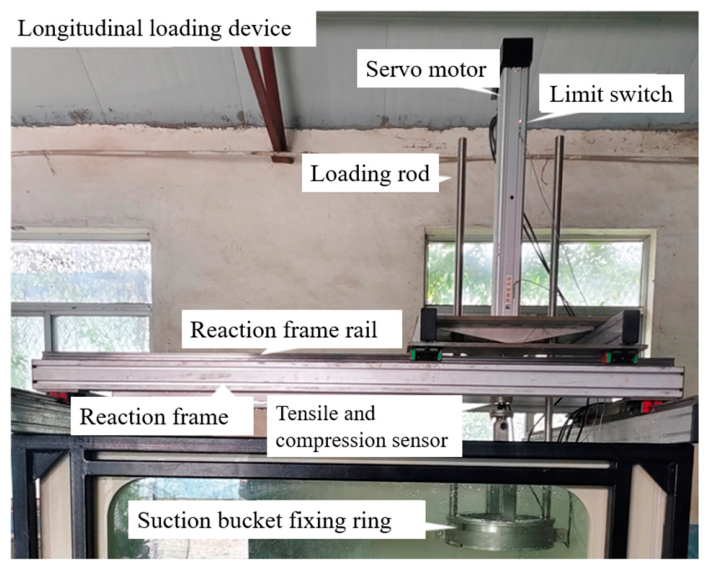
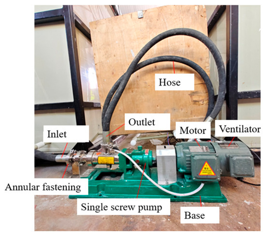
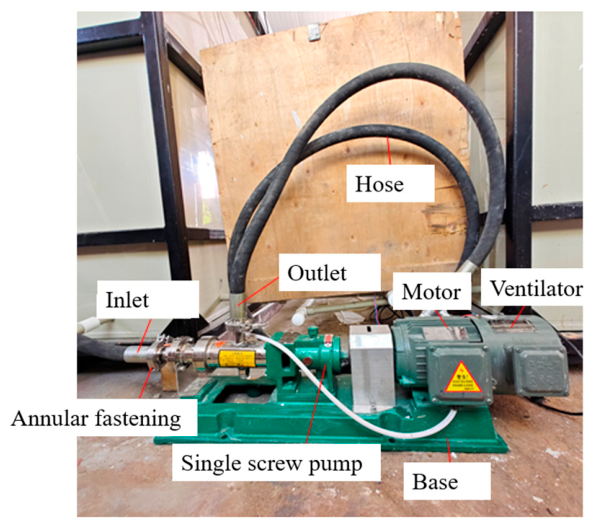
Figure 1, Figure 2, Figure 3, Figure 4 and Figure 5 illustrate the main components of the experimental system. Figure 1 shows the model box and boundary condition. Figure 2 shows the transparent suction bucket model. Figure 3 shows the vertical loading system. Figure 4 shows the grouting system. Figure 5 shows the underwater monitoring system.
Figure 1.
Model box.
Figure 2.
The bucket foundation model.
Figure 3.
The overall layout of the vertical loading system.
Figure 4.
The grouting system.
Figure 5.
The underwater monitoring system.
It should be noted that all tests in this study were conducted under 1 g laboratory conditions, and prototype-level effective stress similitude was not achieved through centrifuge modelling. Therefore, the stress level in the present model tests is considerably lower than that in full-scale offshore wind suction bucket foundations.
Accordingly, the objective of the present tests is not to provide direct quantitative prediction of prototype foundation capacity, but to compare the relative effects of inside-trapped water, cyclic loading, and remedial grouting under the same model scale, sand preparation procedure, and loading conditions.
The model tests were conducted in a rigid model box with internal dimensions of 1500 mm × 1500 mm × 1500 mm. The model box was used to contain the saturated sand bed and overlying water. During testing, the water level was maintained above the sand surface to ensure that the suction bucket foundation was tested under submerged and saturated conditions. The size of the model box was selected to reduce boundary effects on the vertical response of the bucket foundation.
The suction bucket model was made of transparent acrylic to allow direct visual observation of the internal soil plug and trapped-water layer. The bucket had an outer diameter mm, a wall thickness of 10 mm, a lid thickness of 40 mm, and a skirt length mm, giving an aspect ratio of . A scale was attached to the bucket wall to measure the penetration depth, soil plug height, and trapped-water thickness during testing. Drainage/venting ports and a grouting port were arranged on the bucket lid to control the water condition beneath the lid and to conduct remedial grouting.
The transparent bucket wall, together with the underwater monitoring system, enabled the evolution of the soil plug and water layer inside the bucket to be observed during penetration, loading, and grouting.
2.2. Sample Preparation and Sand Properties
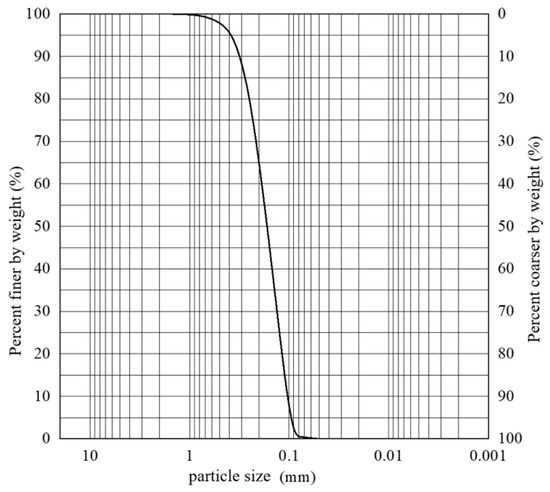
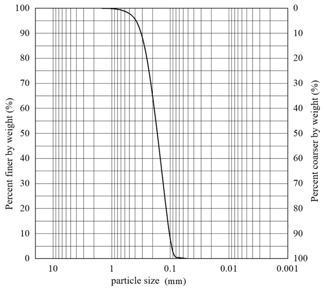
The model ground was prepared using standard sand from Fujian Province. Before testing, it was dried, sieved, and thoroughly mixed to ensure consistent material properties among different tests. To improve the reproducibility of the experiments and to facilitate comparison with previous studies on suction bucket foundations, the grain-size distribution and basic physical properties of the sand were determined.
The grain-size distribution was obtained from sieve analysis, and the particle size distribution curve is shown in Figure 6; the sand properties are shown in Table 1.
Figure 6.
The particle size distribution curve.
Table 1.
The mechanical properties of the sand used in the model tests.
The model sand bed was prepared by pluviation under submerged conditions. In this study, this procedure is referred to as wet pluviation, meaning that the sand was rained through an overlying water layer into the model box, rather than pluviated in air and subsequently saturated. This preparation method has been used in previous studies for reconstituted sand specimens because it can provide initially submerged specimens and reproducible density states [17,18].
Before sample preparation, the Fujian standard sand was dried, sieved, and thoroughly mixed to ensure consistency in particle composition. Water was first introduced into the model box, and the sand was then slowly and uniformly pluviated into the water through a funnel or sand-raining device. During pluviation, the outlet movement path, movement speed, sand flow rate, and layer thickness were kept as consistent as possible among different tests. After each layer was deposited, the sand surface was gently levelled before the next layer was placed. The target global relative density was controlled at approximately based on the dry mass of sand and the final volume of the prepared sand bed.
The homogeneity of the sand bed was controlled mainly through the standardized preparation procedure described above. Visual inspection was used to identify obvious macroscopic defects, such as local accumulation, layering, air pockets, or surface unevenness. However, no pore pressure transducers, miniature cone penetration tests, or local density sampling were used during sample preparation. Therefore, the degree of saturation and local density uniformity could not be quantitatively verified. In the present study, the term “submerged sand bed” is used to describe the prepared model ground, and the potential influence of local variations in saturation or density is acknowledged as an experimental limitation.
2.3. Experimental Process
The model tests were conducted in the following sequence: preparation of the sand bed, installation and penetration of the suction bucket, control of the trapped-water condition, monotonic or cyclic vertical loading, remedial grouting, and post-grouting loading.
After the sand bed was prepared, the suction bucket model was placed vertically at the centre of the sand surface. A level gauge and guiding device were used to ensure that the bucket axis remained vertical, thereby reducing eccentric penetration and eccentric loading. The bucket installation was conducted using self-weight penetration followed by suction penetration. The target penetration depth was 300 mm, corresponding to full skirt penetration.
During penetration, the penetration depth h, soil plug height hs, and trapped-water thickness hw were recorded using the scale attached to the transparent bucket wall and the underwater camera system. After the target penetration depth was reached, penetration was stopped and the model was left undisturbed until the soil plug and water layer became approximately stable. The trapped-water condition was then adjusted or confirmed before subsequent loading.
Each test condition was conducted using an independently prepared sand bed. After one test condition was completed, the disturbed sand in the model box was removed or reworked, and the sand bed was prepared again using the same preparation method. The different test cases were not conducted consecutively on adjacent profiles within the same sand bed. This procedure was adopted to avoid the influence of local density change, soil plug disturbance, and residual deformation caused by previous penetration, loading, or grouting.
Each main test condition was repeated three times to evaluate repeatability. The repeated tests were conducted using freshly prepared or fully reconstituted sand beds, rather than using zones that had already been penetrated, loaded, or grouted. After one test was completed, the disturbed sand in the test area was removed or fully reworked, and the model ground was re-prepared using the same submerged pluviation procedure. The bucket was then installed in a fresh or reconstituted profile before the next replicate test. This procedure was adopted to reduce the influence of residual deformation, local density change, soil plug disturbance, and grout residue from previous tests.
To ensure comparability among different trapped-water conditions, the thickness of the water layer beneath the bucket lid was controlled and verified before loading. Two target trapped-water conditions were considered in this study: a condition without an obvious trapped-water layer (hw = 0 cm) and a condition with a target trapped-water thickness of 2 cm (hw = 2 cm).
To quantify the evolution of foundation stiffness during cyclic loading, the secant stiffness of the load–displacement loop in the -th cycle was used as the cyclic stiffness index:
where is the secant cyclic stiffness in the -th cycle; and are the maximum and minimum vertical loads in that cycle, respectively; and and are the corresponding maximum and minimum vertical displacements. Therefore, the cyclic stiffness used in this study represents the overall secant relationship between load amplitude and displacement amplitude within each cycle, rather than the tangent stiffness at the zero-load point.
The cyclic loading was applied as one-way compressive cyclic loading, with a mean load of and a load amplitude of . The loading rate was 0.2 mm/s, and the total number of cycles was 1000. The interpretation of cyclic stiffness evolution in this study is based mainly on the measured load–displacement response and visual observations.
Before the cyclic loading tests, the reference ultimate vertical resistance for each condition was determined from independent monotonic vertical compression tests conducted under the same initial condition. The ultimate resistance was interpreted from the monotonic load–displacement curve using the double-tangent method. For the no-trapped-water cyclic test H0M20A20S, was obtained from the corresponding monotonic test H0S. For the 2 cm trapped-water cyclic test H2M20A20S, was obtained from the corresponding monotonic test H2S. For the grouted cyclic tests, was determined from monotonic tests conducted after the trapped-water space had been filled with the same grouting material.
The cyclic loading was applied as one-way compressive cyclic loading with a mean load ratio of and a load amplitude ratio of . Therefore, the vertical cyclic load varied between approximately and . The loading rate was 0.2 mm/s, and the total number of cycles was 1000. The used in the cyclic loading protocol was not back-calculated from the cyclic tests, but was obtained from the corresponding reference monotonic tests described above.
The remedial grouting tests were conducted to evaluate the recovery of the vertical load-transfer path and bearing performance after filling the trapped-water space beneath the bucket lid. Before grouting, a trapped-water layer with a target thickness of 2 cm was first formed using the procedure described above, and the water layer thickness and soil plug condition were confirmed using the scale on the transparent bucket wall and the underwater camera system.
The grouting materials used in this study were bentonite–water slurries. No sand was intentionally added to the grouting material; the sand mentioned in this paper refers only to the foundation soil in the model box. The slurry was prepared by mixing dry bentonite powder with water. Three bentonite-to-water mass ratios were adopted, namely , , and , where is the mass of dry bentonite powder and is the mass of mixing water. Accordingly, the terms “20% bentonite”, “60% bentonite”, and “100% bentonite” in this paper refer to the bentonite-to-water mass ratio of the injected slurry.
For each slurry, the dry bentonite powder was gradually added to water and mechanically mixed until a visually homogeneous slurry without obvious agglomeration was obtained. The slurry was then allowed to stand to reduce entrapped air and was gently remixed before injection. The bentonite slurry was selected as a pumpable, low-strength filling material to investigate the recovery of vertical load-transfer after filling the trapped-water space beneath the bucket lid. It was not intended to simulate structural cement-based grout used in prototype offshore foundation engineering.
It should be noted that the bentonite slurry used in this study was selected as a pumpable, low-strength filling material to investigate the recovery of load-transfer after filling the trapped-water space, rather than to simulate structural cement-based grouting used in full-scale offshore engineering. Cement-based or cement–bentonite composite grouts are more commonly used in practical offshore foundation engineering and should be further evaluated in future studies.
2.4. Experiment Conditions
To systematically examine how the water-film effect and remedial grouting influence the vertical bearing characteristics of suction bucket foundations in sandy soil, experiments were conducted as summarized in Table 2. The test conditions are now defined according to penetration rate, target trapped-water thickness, grouting material, and cyclic loading parameters. SMS1–SMS3 denote penetration observation tests. H0 and H2 denote target trapped-water thicknesses of 0 cm and 2 cm. G20, G60, and G100 denote bentonite contents of 20%, 60%, and 100%. M20 and A20 denote and , respectively. S denotes sand foundation condition.
Table 2.
Experiment conditions.
3. Results
All comparative tests were conducted using the same suction bucket model, target penetration depth, sand preparation procedure, and target global relative density. For each main test condition, three repeated tests were conducted. The characteristic values reported in the tables and bar charts, including the ultimate bearing capacity and the final cumulative displacement after cyclic loading, are presented as arithmetic mean values of the repeated tests. The corresponding dispersion ranges were also checked to assess repeatability.
For the full load–displacement curves and cyclic stiffness evolution curves, representative curves are presented to show the typical response trend of each condition. These representative curves were selected from the repeated tests based on their consistency with the mean characteristic values. This approach avoids excessive visual overlap and avoids artificial smoothing that may occur if complete cyclic curves are directly averaged point by point.
The trapped-water conditions were defined based on the observed target water layer thickness before loading. The condition hw = 0 cm indicates that no obvious continuous water layer was observed beneath the bucket lid within the measurement resolution of the present test system. It does not mean the complete absence of pore water or microscopic water films. The condition hw = 2 cm indicates that the initial trapped-water layer beneath the bucket lid was controlled to approximately 2 cm before loading.
The results are mainly compared using dimensionless parameters. During penetration, h/L, hs/L and hw/L are used to describe the penetration depth, soil plug height, and trapped-water thickness, respectively. During vertical loading, x/D is used for vertical displacement, and V/γ′D3 is used for dimensionless vertical bearing capacity. During cyclic loading, Δx/D is used for dimensionless cumulative displacement, and kN represents the secant cyclic stiffness in the N-th cycle. The ultimate bearing capacity was determined using the double-tangent method applied to the load–displacement curve.
Since this study is based on 1 g laboratory model tests, the following results are intended mainly for relative comparison among different test conditions under the same model scale, sand preparation procedure, and loading protocol.
3.1. Study on the Influence of Inside-Trapped Water Formation
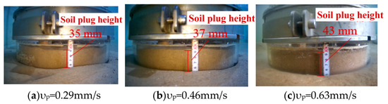
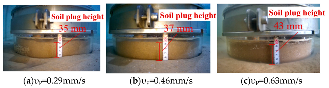
A inside-trapped water formed at all three penetration rates. The final measured soil plug heights were 35 mm, 37 mm, and 43 mm, respectively (Figure 7). Within the range of penetration rates experimented in the SMS experiment, soil plug height increased with increasing penetration rate.
Figure 7.
Final soil plug height under different penetration rates.
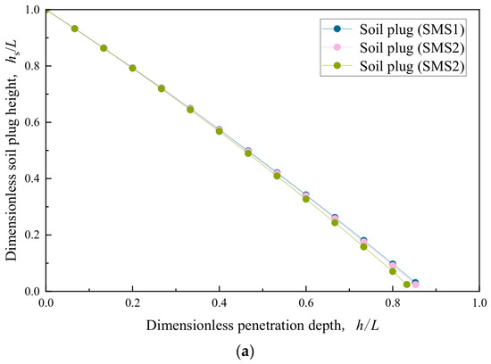
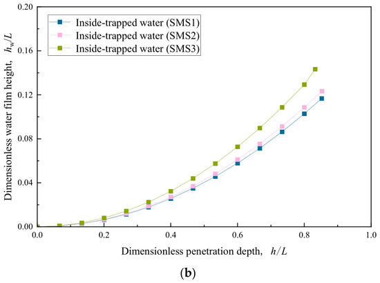
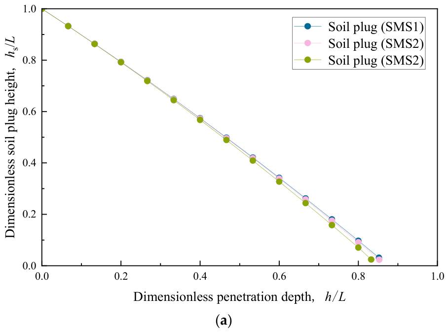
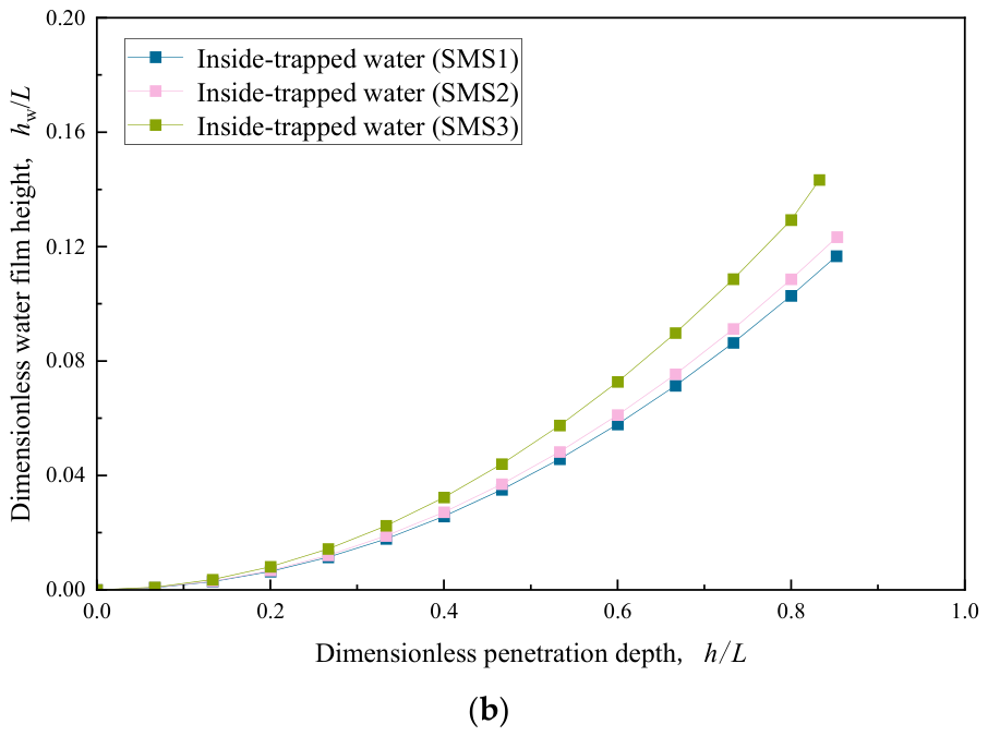
Figure 8 shows the evolution of the internal soil plug and trapped-water layer during bucket penetration. To improve readability, the results are presented in two separate subfigures without using a secondary axis. Figure 8a shows the variation in normalized soil plug height, , with normalized penetration depth, . Figure 8b shows the corresponding variation in normalized trapped-water thickness, , with .
Figure 8.
Evolution of the internal soil plug and trapped-water layer during bucket penetration: (a) variation in normalized soil plug height, , with normalized penetration depth, ; (b) variation in normalized trapped-water thickness, , with normalized penetration depth, .
As the penetration depth increased, the soil plug height generally increased, indicating progressive upward movement or accumulation of sand inside the bucket during suction penetration. In contrast, the trapped-water thickness beneath the bucket lid decreased as penetration proceeded. This trend suggests that the development of the internal soil plug progressively reduced the available space for the trapped-water layer. Comparing the three penetration rates, the final soil plug height increased from 35 mm to 43 mm as the penetration rate increased from 0.29 mm/s to 0.63 mm/s, whereas the final trapped-water thickness remained within a relatively narrow range of 7.1–9.4 mm. These results indicate that penetration rate influenced the soil plug development more clearly than the final trapped-water thickness within the tested range.
Table 3 presents the experiment results. During suction penetration of the bucket foundation, the penetration rate strongly influences the development of the inside-trapped water and the soil plug. As the penetration rate increases from 0.29 mm/s to 0.63 mm/s, the soil plug height increases from 35 mm to 43 mm while the water-film thickness falls from 9.4 mm to 7.3 mm. Higher penetration rates place the sandy soil in an effectively undrained state; correspondingly high pumping rates can draw external soil into the bucket.
Table 3.
Experimental results.
3.2. Study on the Influence of Inside-Trapped Water on the Bearing Characteristics
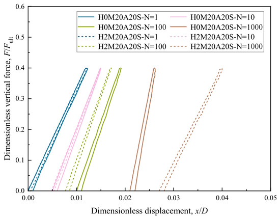
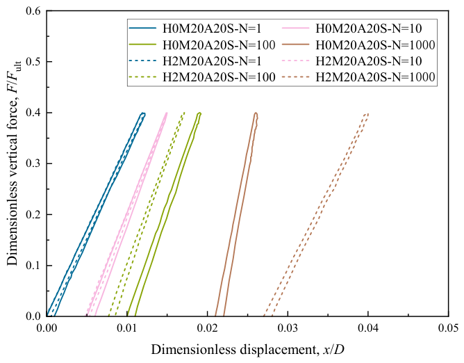
Figure 9 shows representative curves of dimensionless vertical force versus dimensionless displacement during cyclic loading of the bucket foundation in sandy soil for N = 1, 10, 100, and 1000 cycles. After 1000 cycles the displacement approaches a steady value. Relative to the initial condition, the maximum cumulative vertical (unidirectional) displacements are 6.18 mm (0.021D) for H0M20A20S and 7.46 mm (0.025D) for H2M20A20S. This comparison indicates that inside-trapped water in the sandy soil substantially increase cumulative displacement under cyclic loading.
Figure 9.
Dimensionless vertical load–displacement response during cyclic loading for the no-trapped-water case H0M20A20S and the 2 cm trapped-water case H2M20A20S.
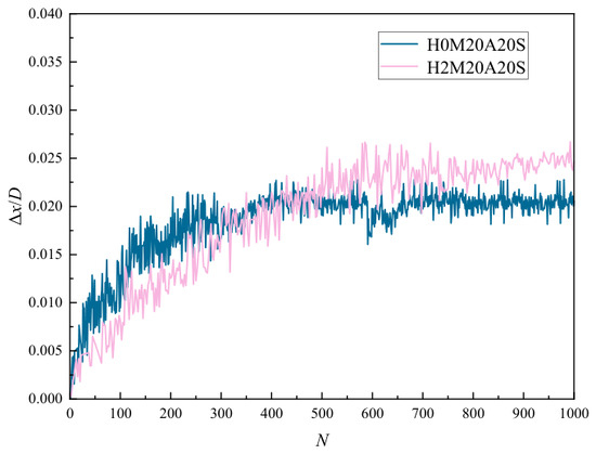
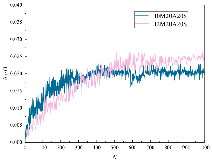
Figure 10 plots the dimensionless cumulative strain of the bucket foundation versus the number of cycles during cyclic loading. In the unidirectional loading tests, the cumulative displacement is downward. The curve shows that the cumulative strain converges to a steady state, and the dimensionless cumulative strain is higher when inside-trapped water is present. This implies that the bucket foundation requires a larger displacement to achieve the same bearing performance under trapped-water conditions.
Figure 10.
Evolution of dimensionless cumulative displacement with the number of cycles for H0M20A20S and H2M20A20S.
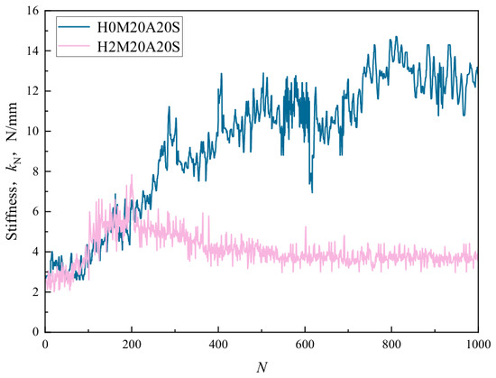
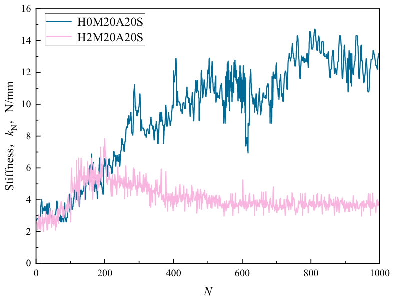
Figure 11 shows the evolution of secant cyclic stiffness with the number of cycles. For the no-trapped-water case H0M20A20S, the cyclic stiffness increased progressively with the number of cycles. This trend may mainly be attributed to particle rearrangement and cyclic densification of the sand around the bucket and within the soil plug. In saturated sand, if the loading rate is sufficiently low for generated pore pressure to dissipate, cyclic loading can reduce the local void ratio and increase the deformation resistance of the foundation–sand system.
Figure 11.
Evolution of secant cyclic stiffness with the number of cycles for H0M20A20S and H2M20A20S.
In contrast, the H2M20A20S case with a 2 cm thick trapped-water layer showed a rise-then-fall stiffness trend. During the initial stage of cyclic loading, cyclic densification of the sand and partial recovery or redistribution of lid–soil plug contact may contribute to the increase in stiffness. As cyclic loading continues, however, the trapped-water layer may prevent stable direct contact between the bucket lid and the internal soil plug. In addition, cyclic loading may induce soil plug disturbance, local interface degradation, and possible pore pressure accumulation. When these adverse effects become more significant than the stiffness increase caused by cyclic densification, the cyclic stiffness decreases and gradually stabilizes.
It should be emphasized that this stiffness decrease should not be interpreted as a reduction in the actual embedment depth of the bucket skirt. The skirt remains physically embedded to its original penetration depth, and the skirt–sand contact remains active. A more appropriate interpretation is that inside-trapped water modifies the load-transfer path among the bucket lid, soil plug, skirt, and surrounding sand. Because no pore water pressure transducers were installed in this study, the possible role of pore pressure development remains a hypothesis that should be verified in future tests.
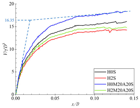
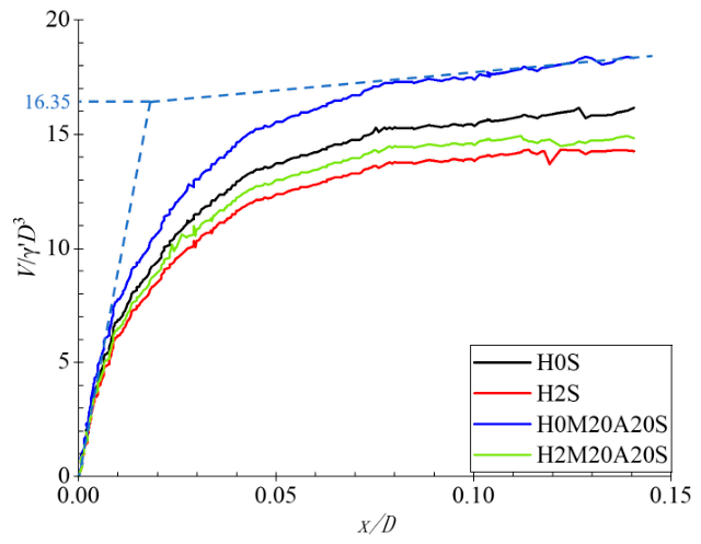
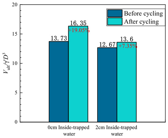
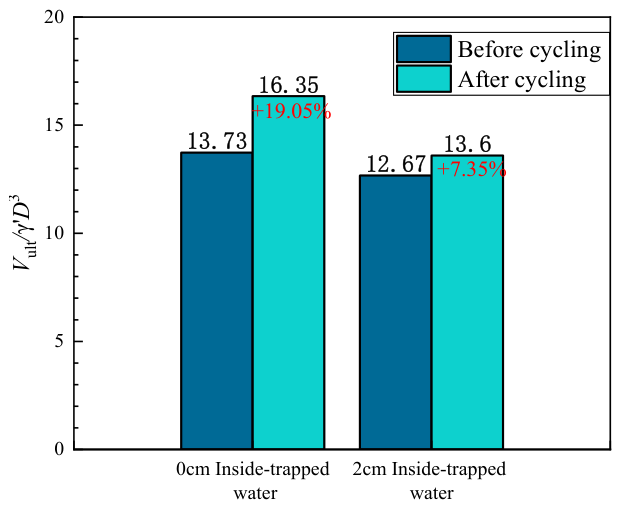
Figure 12 shows the dimensionless vertical bearing capacity curves under different trapped-water and cyclic loading conditions. Figure 13 compares the dimensionless vertical ultimate bearing capacity before and after cyclic loading under different trapped-water conditions. Under monotonic loading, the dimensionless vertical bearing capacities of H0S and H2S were 13.73 and 12.67, respectively. After cyclic loading, the corresponding values of H0M20A20S and H2M20A20S were 16.35 and 13.60, respectively, representing increases of 19.05% and 7.35% respectively compared with the monotonic loading conditions. These key values are summarized in Table 4.
Figure 12.
Dimensionless vertical bearing capacity curves under different trapped-water and cyclic loading conditions.
Figure 13.
Comparison of dimensionless vertical ultimate bearing capacity before and after cyclic loading under different trapped-water conditions.
Table 4.
Experimental results.
The results indicate that the trapped-water cases exhibited lower dimensionless bearing capacity than the corresponding no-trapped-water cases under the present model test conditions. Under monotonic loading, the 2 cm trapped-water case showed a lower bearing capacity than the no-trapped-water case. After cyclic loading, the reduction was more pronounced.
This behaviour can be explained by the change in vertical load-transfer mechanism caused by the trapped-water layer. In the no-trapped-water case, the bucket lid can maintain direct contact with the internal soil plug, allowing the vertical load to be transferred through the lid–soil plug contact, together with the contribution from skirt-side resistance and resistance near the bucket rim. In the trapped-water case, the water layer beneath the lid weakens or interrupts direct lid–soil plug contact. Consequently, the vertical load cannot be fully transferred from the lid to the soil plug, and the foundation resistance depends more strongly on skirt-side resistance and resistance mobilized near the bucket rim.
3.3. Study on the Influence of Grouting on the Bearing Characteristics
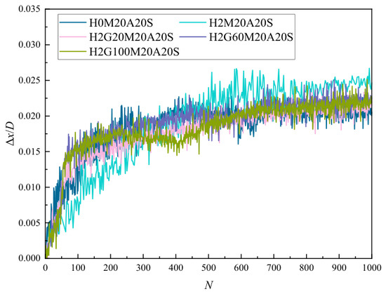
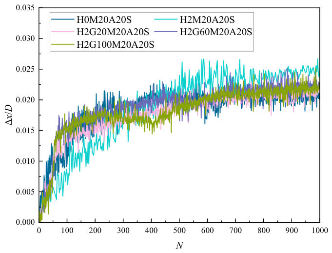
Figure 14 displays the dimensionless cumulative strain of the bucket foundation as a function of cycle number during the cyclic loading. The plot shows that the cumulative strain eventually stabilizes, and that the dimensionless cumulative strain is higher when a inside-trapped water is present. This implies that, in the presence of a inside-trapped water, the bucket foundation must undergo larger displacements to attain the same bearing performance. Grouting substantially reduces the increased cumulative displacement caused by the inside-trapped water under cyclic loading, and the choice of grouting material has only a minor effect.
Figure 14.
Evolution of dimensionless cumulative displacement with the number of cycles for ungrouted and grouted cases.
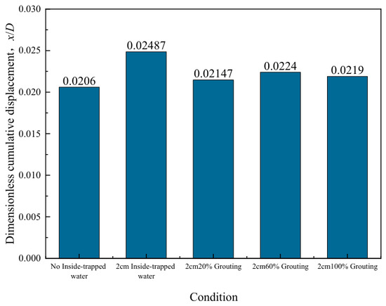
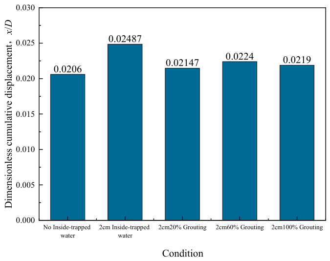
Figure 15 compares the dimensionless cumulative strain of the bucket foundation after cyclic loading. The data confirm that the presence of inside-trapped water increases the dimensionless cumulative strain under cyclic loading, whereas grouting significantly mitigates this increase in cumulative displacement caused by trapped water.
Figure 15.
Comparison of dimensionless cumulative displacement after 1000 cycles under different trapped-water and grouting conditions.
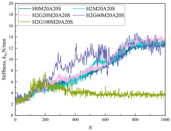
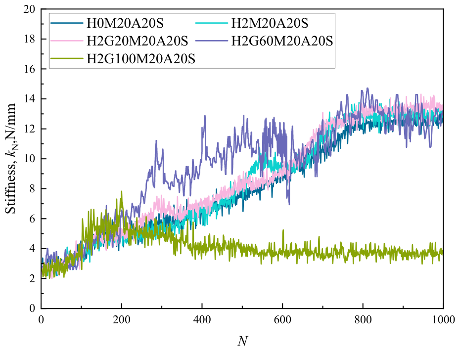
Figure 16 plots the cyclic stiffness of the bucket foundation versus the number of cycles. The stiffness increases slightly with increasing cycles, reflecting the densification of the surrounding soil and the resulting increase in foundation resistance. After grouting, the stiffness curve approaches that measured under trapped-water-free conditions but remains slightly lower. This suggests that grouting substantially eliminates trapped water in the sand but cannot fully restore the bearing performance of the trapped-water-free state, likely because trapped water has already reduced the effective embedment depth of the foundation, an effect that cannot be completely reversed by grouting.
Figure 16.
Evolution of secant cyclic stiffness with the number of cycles for ungrouted and grouted cases.
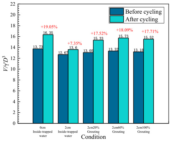
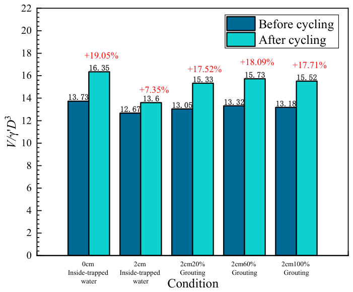
Figure 17 compares the dimensionless vertical ultimate bearing capacity before and after cyclic loading for ungrouted and grouted cases. The grouted cases correspond to 2 cm trapped-water conditions treated with 20%, 60%, and 100% bentonite slurry. For the 20%, 60%, and 100% grouting cases, the dimensionless vertical ultimate bearing capacity under cyclic loading increased by 17.52%, 18.09%, and 17.71%, respectively, compared with the corresponding monotonic loading conditions.
Figure 17.
Comparison of dimensionless vertical ultimate bearing capacity before and after cyclic loading for ungrouted and grouted cases.
To present the recovery effect after grouting more clearly, Table 5 summarizes the post-cyclic dimensionless bearing capacities of the ungrouted and grouted trapped-water cases. Compared with the ungrouted 2 cm trapped-water case H2M20A20S, the post-cyclic bearing capacities of the 20%, 60%, and 100% bentonite grouting cases increased by approximately 12.7%, 15.7%, and 14.1%, respectively.
Table 5.
Summary of dimensionless vertical bearing capacities under different test conditions.
The results show that, under the present model test conditions, all grouted cases exhibited higher post-cyclic bearing capacity than the ungrouted trapped-water case. However, the differences among the three grouted cases were relatively small. The maximum difference among the post-cyclic bearing capacities of the grouted cases was approximately 0.40, corresponding to about 2.6% of their mean value.
Under the present low-stress 1 g model conditions, the three bentonite slurry cases produced similar levels of bearing capacity recovery.
The improved performance observed even in the 100% bentonite case suggests that the grouting effect in this study was mainly associated with filling the trapped-water space and restoring the load-transfer path, rather than with the intrinsic strength of the grout material. Therefore, bentonite slurry in this study should be regarded as a low-strength filling material used for mechanism identification, rather than as a structural grout for prototype offshore foundations. For engineering applications, cement-based or cement–bentonite composite grouts should be further investigated with respect to strength, stiffness, durability, scour resistance, and long-term cyclic stability.
4. Discussion
The results presented above indicate that inside-trapped water can adversely affect the cyclic displacement response and post-cyclic bearing performance of suction bucket foundations in sand under the present 1 g model test conditions. However, the mechanism should not be described as a reduction in actual or effective embedment depth. The bucket skirt remains physically embedded throughout the test. The main influence of the trapped-water layer is to modify the load-transfer path between the bucket lid and the internal soil plug.
In the absence of an observable trapped-water layer, the bucket lid and soil plug can form direct contact, allowing vertical load to be transmitted through the lid–soil plug contact, in addition to skirt-side resistance and resistance near the bucket rim. In the presence of a trapped-water layer, this direct contact is weakened or interrupted. The foundation response then becomes more dependent on skirt-side resistance, rim resistance, and pressure transmission through the water layer. Under cyclic loading, this modified load-transfer condition may interact with cyclic densification, soil plug disturbance, local contact degradation, and possible pore pressure development.
The present interpretation is subject to several limitations. First, pore water pressure transducers were not installed beneath the bucket lid or within the internal soil plug. Therefore, the development and dissipation of excess pore pressure under cyclic loading could not be directly quantified. Second, the loading frequency and drainage path were not systematically varied, and the local drainage condition cannot be rigorously classified as fully drained, partially drained, or locally undrained. Third, because the experiments were conducted under 1 g model conditions, prototype effective stress similitude was not achieved. The measured bearing capacity factors and percentage changes should therefore be regarded as comparative model-scale indicators rather than prototype-scale design parameters.
Despite these limitations, the comparative results provide useful evidence for understanding how a trapped-water layer beneath the bucket lid can alter the cyclic response and post-cyclic bearing performance of suction bucket foundations, and how filling this space through remedial grouting can partially restore the load-transfer path.
5. Conclusions
This study investigated the influence of inside-trapped water and remedial grouting on the vertical bearing behaviour of suction bucket foundations in sand through 1 g laboratory model tests. The results are mainly intended to compare the relative responses of different trapped-water and grouting conditions under the same model scale, sand preparation procedure, and loading protocol. Based on the present experimental conditions, the following conclusions can be drawn:
- (1)
- During suction bucket penetration, a soil plug and an inside-trapped water layer can form inside the bucket. Within the penetration rate range tested in this study, the final soil plug height increased with increasing penetration rate, indicating that the installation process affects the formation state of the internal soil plug and trapped-water layer. The trapped-water thicknesses measured during penetration observation tests provide a basis for defining the controlled trapped-water conditions used in the subsequent loading tests.
- (2)
- Inside-trapped water does not change the actual penetration depth of the bucket skirt. Instead, it modifies the vertical load-transfer path among the bucket lid, internal soil plug, skirt, and surrounding sand. When a trapped-water layer exists beneath the bucket lid, the direct contact between the lid and the soil plug is weakened or interrupted, and the vertical load is transferred more strongly through skirt-side resistance, rim resistance, and pressure transmission through the water layer. This load-transfer change is the main reason for the larger cumulative displacement and lower post-cyclic bearing response observed in the trapped-water case.
- (3)
- Under cyclic vertical loading, the no-trapped-water case showed a progressive increase in secant cyclic stiffness, which may be associated with cyclic densification of the sand around the bucket and within the soil plug. In contrast, the 2 cm trapped-water case exhibited a rise-then-fall stiffness trend followed by stabilization. This behaviour may be related to the combined effects of initial cyclic densification, evolution of lid–soil plug contact, soil plug disturbance, local interface degradation, and possible excess pore pressure development.
- (4)
- Remedial grouting can fill the trapped-water space or local void beneath the bucket lid and form a more continuous contact system among the lid, grout-filled zone, and soil plug. As a result, the vertical load-transfer path can be partially restored. Compared with the ungrouted 2 cm trapped-water case, the grouted cases showed smaller cumulative cyclic displacement and higher post-cyclic vertical bearing capacity under the present model test conditions.
- (5)
- The post-cyclic dimensionless vertical bearing capacities of the 20%, 60%, and 100% bentonite grouting cases were 15.33, 15.73, and 15.52, respectively, corresponding to increases of approximately 12.7%, 15.7%, and 14.1% relative to the ungrouted trapped-water case. The differences among the three grouted cases were relatively small within the present dataset. However, because repeated tests and statistical analyses were limited, this observation should not be interpreted as statistical evidence that grout composition has no significant influence. A more appropriate interpretation is that, under the present low-stress 1 g model conditions, the improvement was mainly associated with filling and sealing the trapped-water space and restoring the load-transfer path, rather than with the intrinsic structural strength of the grout material.
Author Contributions
Conceptualization, H.Z. and M.Q.; methodology, H.Z.; software, H.Z. and M.Q.; validation, H.Z., T.L. and J.D.; formal analysis, H.Z.; investigation, Z.W.; resources, Z.W.; data curation, J.X.; writing—original draft preparation, H.Z.; writing—review and editing, H.Z.; visualization, H.Z.; supervision, H.Z.; project administration, H.Z.; funding acquisition, H.Z. All authors have read and agreed to the published version of the manuscript.
Funding
This research was funded by Scientific Research Funds of China Three Gorges Group Co., Ltd., (WWKY-2020-0721 and NBZZ202300461).
Data Availability Statement
The original contributions presented in this study are included in the article. Further inquiries can be directed to the corresponding authors.
Conflicts of Interest
Authors Hanbo Zhai, Ming Qin, Tingting Li and Jialin Dai are employed by the Institute of Science and Technology Research, China Three Gorges Corporation; Zhongping Wang is employed by China Three Gorges Renewables (Group) Co., Ltd.; Jun Xiang is employed by China Three Gorges Corporation Guangdong Branch. The authors declare that the research was conducted in the absence of any commercial or financial relationships that could be construed as a potential conflict of interest. Besides, the authors declare that this study received funding from the Scientific Research Funds of China Three Gorges Group Co., Ltd. The funder was not involved in the study design, collection, analysis, interpretation of data, the writing of this article or the decision to submit it for publication.
References
- Cerfontaine, B.; Collin, F.; Charlier, R. Numerical modelling of transient cyclic vertical loading of suction caissons in sand. Géotechnique 2016, 66, 121–136. [Google Scholar] [CrossRef] [Scilit]
- Bienen, B.; Klinkvort, R.T.; O’Loughlin, C.D.; Zhu, F.; Byrne, B.W. Suction caissons in dense sand, part II: Vertical cyclic loading into tension. Géotechnique 2018, 68, 953–967. [Google Scholar] [CrossRef] [Scilit]
- Da Silva Pereira, F.; Bienen, B.; O’Loughlin, C.D. Mind the gap–an experimental study on the need for grouting suction buckets in sand under vertical cyclic loading. Géotechnique 2024, 74, 1487–1502. [Google Scholar] [CrossRef] [Scilit]
- Zhang, P.; Guo, Y.; Liu, Y.; Ding, H. Experimental study on installation of hybrid bucket foundations for offshore wind turbines in silty clay. Ocean Eng. 2016, 114, 87–100. [Google Scholar] [CrossRef] [Scilit]
- Zhang, P.; Zhang, Z.; Liu, Y.; Ding, H. Experimental study on installation of composite bucket foundations for offshore wind turbines in silty sand. J. Offshore Mech. Arct. Eng. 2016, 138, 061901. [Google Scholar] [CrossRef] [Scilit]
- Nielsen, S.D. Finite element modeling of the tensile capacity of suction caissons in cohesionless soil. Appl. Ocean Res. 2019, 90, 101866. [Google Scholar] [CrossRef] [Scilit]
- Ding, H.; Peng, Y.; Zhang, P.; Zhai, H.; Jia, N. Model experiments on the penetration resistance of bucket foundations for offshore wind turbines in sand. J. Mar. Sci. Eng. 2020, 8, 368. [Google Scholar] [CrossRef] [Scilit]
- Le, C.; Ding, H.; Zhang, P. Prototype experimenting for the partial removal and re-penetration of the mooring dolphin platform with multi-bucket foundations. Mar. Struct. 2018, 59, 80–93. [Google Scholar] [CrossRef] [Scilit]
- Thieken, K.; Achmus, M.; Schröder, C. On the behavior of suction buckets in sand under tensile loads. Comput. Geotech. 2014, 60, 88–100. [Google Scholar] [CrossRef] [Scilit]
- Vicent, S.; Kim, S.R.; Van Tung, D.; Bong, T. Effect of loading rate on the pullout capacity of offshore bucket foundations in sand. Ocean Eng. 2020, 210, 107427. [Google Scholar] [CrossRef] [Scilit]
- Hirai, H. Analysis of cylindrical and rectangular bucket foundations subjected to vertical and lateral loads in sand using a three-dimensional displacement approach. Soils Found. 2020, 60, 45–62. [Google Scholar] [CrossRef] [Scilit]
- Barari, A.; Ibsen, L.B.; Taghavi Ghalesari, A.; Larsen, K.A. Embedment effects on vertical bearing capacity of offshore bucket foundations on cohesionless soil. Int. J. Geomech. 2017, 17, 04016110. [Google Scholar] [CrossRef] [Scilit]
- Hung, L.C.; Lee, S.; Tran, N.X.; Kim, S.R. Experimental investigation of the vertical pullout cyclic response of bucket foundations in sand. Appl. Ocean Res. 2017, 68, 325–335. [Google Scholar] [CrossRef] [Scilit]
- Haddad, A.; Amini, R.; Barari, A. Effect of embedment on the vertical capacity of bucket foundation in loose saturated sand: Physical modeling. Mar. Georesour. Geotechnol. 2019, 37, 366–374. [Google Scholar] [CrossRef] [Scilit]
- Gao, Y.; Qiu, Y.; Li, B.; Li, D.; Sha, C.; Zheng, X. Experimental studies on the anti-uplift behavior of the suction caissons in sand. Appl. Ocean Res. 2013, 43, 37–45. [Google Scholar] [CrossRef] [Scilit]
- Shonberg, A.; Harte, M.; Aghakouchak, A.; Brown, C.S.D.; Andrade, M.P.; Liingaard, M.A. Suction bucket jackets for offshore wind turbines: Applications from in situ observations. In Proceedings of the 19th International Conference on Soil Mechanics and Geotechnical Engineering (ICSMGE 2017), Seoul, Republic of Korea, 17–22 September 2017. [Google Scholar]
- Vaid, Y.P.; Negussey, D. Preparation of reconstituted sand specimens. In Advanced Triaxial Testing of Soil and Rock; ASTM STP 977; ASTM International: West Conshohocken, PA, USA, 1988. [Google Scholar] [CrossRef] [Scilit]
- Lagioia, R.; Sanzeni, A.; Colleselli, F. Air, water and vacuum pluviation of sand specimens for the triaxial apparatus. Soils Found. 2006, 46, 61–67. [Google Scholar] [CrossRef] [Scilit]

Disclaimer/Publisher’s Note: The statements, opinions and data contained in all publications are solely those of the individual author(s) and contributor(s) and not of MDPI and/or the editor(s). MDPI and/or the editor(s) disclaim responsibility for any injury to people or property resulting from any ideas, methods, instructions or products referred to in the content. |
© 2026 by the authors. Licensee MDPI, Basel, Switzerland. This article is an open access article distributed under the terms and conditions of the Creative Commons Attribution (CC BY) license.