


Abstract
This study presents the design, development, and experimental validation of a novel cable-driven shoulder exosuit (CDSE) for upper limb rehabilitation and assistance. Unlike existing exoskeletons, which are often bulky, limited in degrees of freedom (DOFs), or impractical for home use, the proposed DSE offers a lightweight (≈2 kg), portable, and wearable solution capable of supporting three shoulder movements: abduction, flexion, and horizontal adduction. The system employs a bioinspired tendon-driven mechanism using Bowden cables, transferring actuation forces from a backpack to the arm, thereby reducing user load and improving comfort. Mathematical models and inverse kinematics were derived to determine cable length variations for targeted motions, while control strategies were implemented using a PID-based approach in MATLAB Simscape-Multibody simulations. The prototype was fabricated in three iterations using PLA, aluminum, and carbon fiber—culminating in a durable and ergonomic final version. Experimental evaluations on a healthy subject demonstrated high accuracy in position tracking (<5% error) and torque profiles consistent with simulation outcomes, validating system robustness. The CDSE successfully supported loads up to 4 kg during rehabilitation tasks, highlighting its potential for clinical and at-home applications. This research contributes to advancing wearable robotics by addressing portability, biomechanical alignment, and multi-DOF functionality in upper limb exosuits.
1. Introduction
Effective upper limb function is a fundamental requirement for performing daily activities and maintaining independence. This is crucial and essential for anyone to carry out their everyday activities. Impairments in upper limb mobility not only curtail the independence of those affected but also significantly diminish their overall quality of life. “Impairments that restrict the capacity to engage in daily activities ultimately result in a heightened risk of mortality and a reduced life expectancy by as much as a decade” [1]. Numerous research articles have already discussed the use of robots in the field of rehabilitation robotics. Gopura conducted a study on exoskeleton robots, primarily focusing on their mechanical design [2]. Bogue’s research delved into the development of exoskeletons and robotic artificial limbs [3]. Maciejasz and colleagues carried out a comprehensive review of various robotic designs aimed at enhancing upper limb rehabilitation systems [4]. Varghese et al. explored the realm of wearable robots for upper limb support and rehabilitation [5]. These developers of robotic devices have played a significant role in advancing upper limb rehabilitation through the evaluation of various technical solutions. This review aims to provide an extensive overview of designs in the past two decades, with a specific emphasis on those related to the shoulder joint. The motivation for this research stems from the critical need for advanced rehabilitation solutions that are both effective and user-friendly, particularly for populations experiencing upper limb disabilities.
- Cable-Driven Exosuits in Rehabilitation Robotics
In recent years, cable-driven exosuits (CDEs) have gained notable attention in assistive robotics due to their lightweight construction and potential to support impaired movements [6,7]. These wearable systems employ tensioned cables and actuators to augment or restore mobility. By adjusting cable tension, they can compensate for muscular weakness and provide functional support [8,9,10,11]. Their applications are diverse, ranging from occupational ergonomics [12] and rehabilitation therapy [13] to everyday assistance [9], sports training, and even head and neck rehabilitation [14,15,16].
- Need for Shoulder-Specific Rehabilitation
The human upper limb, particularly the shoulder, plays a central role in daily activity. Impairments in this region significantly affect autonomy and quality of life. Despite considerable research over the past two decades, only a limited number of wearable robotic devices targeting the shoulder have demonstrated strong therapeutic outcomes or clinical validation. Many designs remain bulky or impractical for home or outpatient use [17].
- Categories of Shoulder Exoskeletons
A number of shoulder exoskeletons (SEs) have been introduced, generally categorized as passive, semi-active, or active systems [18,19]. Passive models use springs or elastic elements to deliver torque during motion but lack adjustability [20,21,22,23]. Semi-active devices improve on this by integrating low-power actuators to tune spring properties [24,25,26,27], though they still rely on the user for energy input. In contrast, active systems offer external powered assistance via motors and batteries, providing adjustable torque and improved user adaptability.
- Current Challenges in High-DOF Systems
Several advanced exoskeletons—such as MEDARM [28], ANYexo training [29], and Harmony [30]—include 3 to 5 degrees of freedom, aiming to mimic natural glenohumeral and clavicular motion. Some rely on multi-link mechanisms [31] or retractable joints [32] to approximate shoulder movement. While this improves anatomical accuracy, the resulting designs are often mechanically complex and difficult to miniaturize, limiting portability [33,34].
- Addressing Misalignment and Discomfort
A persistent challenge in many upper limb exosuits is the mismatch between mechanical joints and the biological shoulder, which can cause discomfort or even injury during prolonged use. Various approaches have been proposed to address this, such as including passive DOFs to adjust joint centers, ergonomic reconfiguration [35,36], or transitioning toward fully flexible, soft exosuits [37,38,39]. While flexible designs reduce joint misalignment, they often lack structural rigidity and can be costly. Recent efforts therefore explore hybrid systems using adaptive or passive joint mechanisms to maintain user comfort while improving alignment [40].
- Design Challenges in Existing Exosuits and Proposed Solution
According to the articles reviewed, the main limitations of existing designs are that they are fixed, non-portable, heavy, restricted to only one or two degrees of freedom, and often unsuitable for home use. Due to the increasing demand for new portable and lightweight designs that can cover more than one or two DOFs of the shoulder joint, the design and simulation of portable, lightweight designs with this feature can be essential. According to the problems mentioned and our goal in this work, the design, simulation, and testing of a novel cable-driven shoulder exosuit as a light wearable device for upper limb rehabilitation were performed to assess its effectiveness in three shoulder joint activities, which include shoulder abduction, shoulder flexion, and shoulder horizontal adduction (flexion). The features of this novel design are its ability to be worn by the user or be wheelchair-mounted, the coverage of three DOFs of the shoulder joint, its light weight, and its ability to be used as a portable device.
Recent studies have explored activity classification, motion tracking, and cognitive rehabilitation to improve exoskeleton/exosuit control. For example, Chen et al. [41] investigates deep learning-based human activity recognition, which includes gesture design and joint angle analysis, providing a robust classification of user intent from multimodal sensors. These methods, which employ sensor fusion, video or IMU data, and advanced classification algorithms, have shown promising results in recognizing complex upper limb tasks and thus have direct relevance to exosuit control. Similarly, other recent works employ convolutional neural networks, transformer architectures, and multimodal sensing (e.g., EMG + IMU) for real-time motion tracking and task recognition. These approaches provide a strong motivation for integrating similar capabilities into CDSEs to enhance adaptive assistance, user intention inference, and safety in more dynamic or unstructured settings.
Unlike many prior cable-driven exosuits that were limited by single-DOF assistance, bulkiness, or the need for laboratory-based pneumatic actuation, the proposed CDSE advances the field in terms of both usability and clinical readiness. Its lightweight structure (~2 kg), with actuators positioned in a backpack to reduce arm-borne load, enhances comfort and portability, making it suitable for prolonged use and daily activities. Moreover, the CDSE simultaneously supports three clinically relevant shoulder motions—abduction, flexion, and horizontal adduction—thereby offering a broader functional range than most reported systems. The experimental evaluation demonstrated consistent performance with <5% position tracking error and the ability to assist loads up to 4 kg, which underscores its robustness for rehabilitation and potential transition from laboratory to clinical or at-home environments. These features collectively highlight the novelty of the CDSE as a practical, multi-DOF, and user-friendly exosuit that addresses longstanding barriers to adoption in clinical rehabilitation.
Following the introduction presented in Section 1, the rest of this paper is organized as follows: Section 2 presents the concept design of the proposed exosuit, including the conceptual, detailed, and implementation stages. Section 3 describes the mathematical modeling of the system, focusing on the configuration of the exosuit with its base and moving arm platforms connected by parallel cables. Section 4 explores rehabilitation scenarios, examining how the exosuit responds and adapts to specific arm movement tasks. Section 5 presents the simulation and control aspects, detailing the simulation setup in the Simscape-Multibody environment and explaining the control of the actuators. Section 6 discusses the prototype and experimental validation, covering the fabrication process with different materials across multiple iterations and providing data and analysis on the exosuit’s performance during real rehabilitation movements. Finally, Section 7 concludes this study by summarizing the key findings and highlighting the potential of the exosuit for practical rehabilitation applications.
2. Design Concept
2.1. Upper Limb Biomechanics
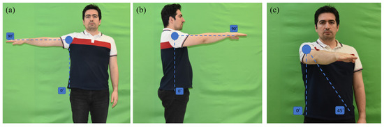
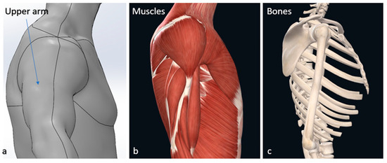
The primary goal is to find better solutions for movement disorders by understanding human anatomy and biomechanics. This knowledge inspires robotic system design, crucial for exoskeletons and exosuits that involve human–robot interaction (HRI) [42,43]. The upper limb, comprising the shoulder, elbow, and wrist, is key in positioning the hand for flexible tasks [44]. The shoulder joint, also known as the glenohumeral joint, permits the arm to achieve increased mobility along three primary axes, thereby enhancing the hand’s range of motion. Within this joint, the arm can perform various movements, including shoulder abduction, flexion, and horizontal adduction (flexion), which are depicted in Figure 1.
Figure 1.
(a): Shoulder abduction. (b): Shoulder flexion. (c): Shoulder horizontal adduction (flexion).
2.2. Shoulder Joints and Muscles
The shoulder comprises the humerus, clavicle, and scapula, with four articulations: scapulothoracic, acromioclavicular, glenohumeral, and sternoclavicular. The glenohumeral joint is the primary one, functioning as a ball and socket joint [45]. It has 3 degrees of freedom (DOFs) [42], with key motions including flexion/extension and abduction/adduction and horizontal adduction (flexion). [46]. The rotator cuff muscles support the glenohumeral joint [47].
2.3. Bioinspired Design
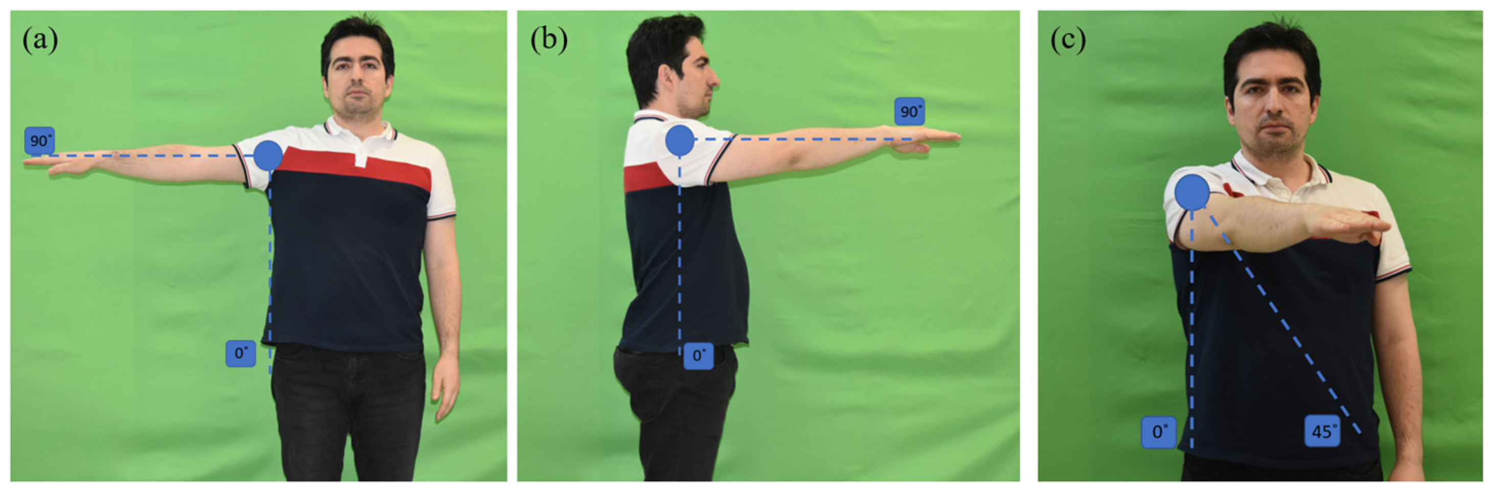
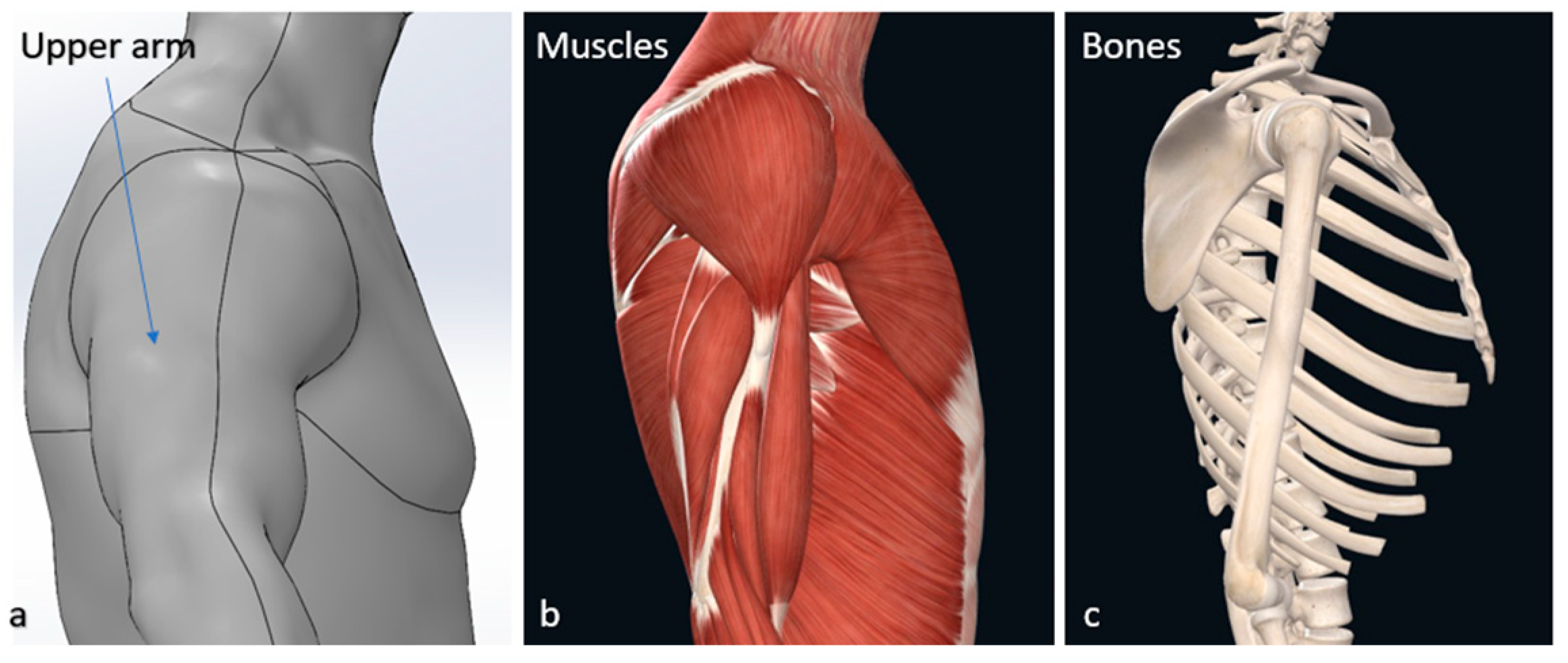
To design a lightweight, wearable system for aiding upper limb movements, we investigated the bone and muscle conditions and proposed replacing drive cables with a bioinspired tendon-driven system to simulate natural shoulder movement. The shoulder’s center of rotation is dynamic but can be approximated as fixed for specific movements, aiding in the design of assistive devices. The key muscles involved in shoulder movements include the deltoid and rotator cuff muscles, which coordinate to stabilize and facilitate shoulder abduction, flexion, and horizontal adduction. This bioinspired design simplifies complex biomechanics, enhancing the development of effective exosuits aligned with human anatomy (Figure 2) [46,48,49].
Figure 2.
(a) Upper arm. (b) Muscles. (c) Bones.
2.4. Design and Development of Exosuit
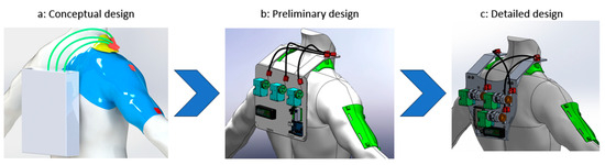
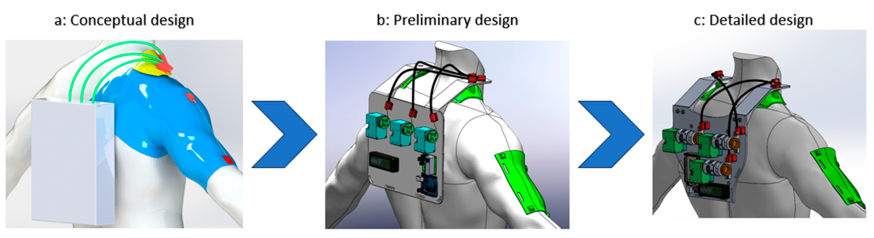
The design phase of the backpack, integral to the development of the exosuit, was meticulously structured into three progressive stages, evolving from conceptual design to detailed design. This phased approach facilitated a systematic and thorough development process. The initial stage, conceptual design, involved brainstorming, preliminary sketches, and basic functional outlines, setting the foundation for this project. The subsequent stage transitioned into an intermediate design phase, where the initial concepts were refined, and more detailed plans were formulated. This stage included the development of prototypes, which were essential for testing and further refinement. The final stage, detailed design, marked the culmination of the design process, where precise specifications, materials, and engineering details were finalized. This stage was critical for ensuring the practical feasibility and functionality of the backpack. The accompanying illustration provides an overview of this comprehensive design phase, visually representing the transition from conceptual ideas to a tangible, detailed design. The design steps are depicted in Figure 3.
Figure 3.
(a) Conceptual design. (b) Preliminary design. (c) Detailed design.
Based on the investigations in our literature review [50] and our existing knowledge, there has been no presentation of an exosuit design that meets the criteria of being portable and lightweight and featuring three degrees of freedom for the shoulder joint. Therefore, the CDSE presented in this article is designed to cover the issues mentioned.
A key consideration in the CDSE design was mitigating shoulder joint misalignment, a common source of discomfort in exosuits. By employing Bowden cables that act only in tension, the system introduces passive compliance, allowing for small natural translations of the glenohumeral joint without rigid mechanical constraint. Additionally, the backpack structure incorporates adjustable anchor points for cable routing, enabling customization to different user anatomies. This reduces static misalignment during donning and short-term use.
2.5. Justification
The justification for the proposed system is grounded in a comprehensive review of exosuit designs published in the last two decades [50], which reveals critical limitations that hinder their clinical and practical translation. Many designs have relied on pneumatic actuators, such as McKibben muscles or inflatable bladders, which generate sufficient force but require compressed air, thereby reducing portability and usability outside laboratory settings [51,52,53]. In contrast, electric actuators, employed in nearly half of the reported designs, enable more compact and portable systems; however, these prototypes often fail to balance torque generation, weight distribution, and multi-joint functionality [54,55,56]. Furthermore, most studies addressed only one or two degrees of freedom (DOFs), and while some designs incorporated three or more DOFs, none achieved the simultaneous control of three shoulder DOFs, a prerequisite for supporting natural and functional upper limb mobility [46,56,57,58]. The issue of weight distribution is also evident, as many systems concentrate mass on the arm, limiting user comfort, with reported device weights ranging from 0.3 kg to over 10 kg [55,59]. To address these gaps, the proposed system integrates electric actuators with a cable-driven transmission that relocates actuation to a backpack, thereby reducing load on the arm while maintaining effective torque transfer. This approach results in a total weight of approximately 2 kg and provides three shoulder DOFs, representing an advancement over existing systems in terms of portability, biomechanical relevance, and usability. Thus, the new design directly responds to the identified shortcomings in actuation methods, weight efficiency, and joint coverage, offering a more practical and scalable solution for soft exosuits [54,55,57,60].
3. Mathematical Modeling of CDSE
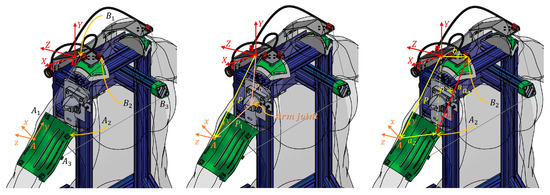
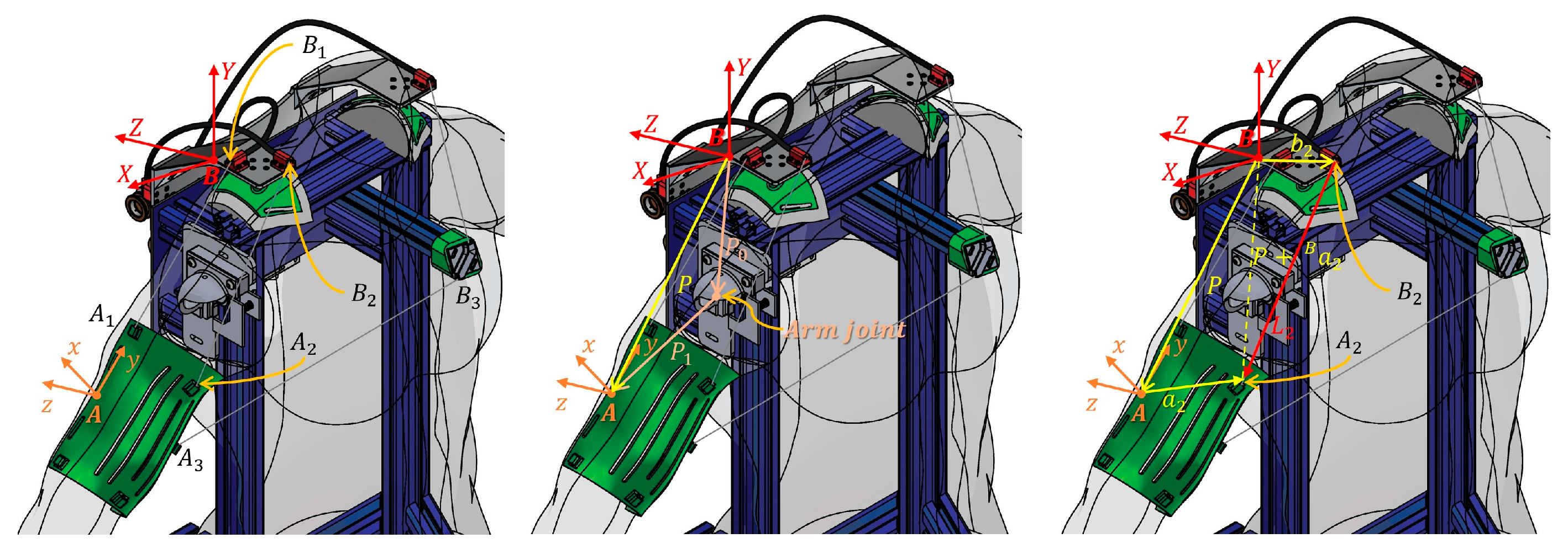
The CDSE for upper limb rehabilitation consists of a base platform and a moving arm platform, and the base platform is connected to the moving arm platform using three cables in a parallel configuration. Figure 4 illustrates the mathematical modeling and analysis carried out for the CDSE. represent the cable driving points on the fixed-base platform. represent the traction points of the moving arm platform. is the arm coordinate system (ACS). is the base coordinate system (BCS) which is fixed on the base platform. The origin of the moving arm system coincides with the midpoint of the traction point and end point of cable 1. When the arm is in its natural position and at rest, the axes of the moving arm coordinates () are along the fixed-base coordinate axes () of the CDSE, where contains cable 1 (which connected to actuator 1), and also and contain cable 2 and cable 3, respectively (which are connected to actuators 2 and 3, respectively).
Figure 4.
Cable-driven shoulder exosuit. (left) CDSE mathematical model. (center) Arm coordination system position. (right) CDSE kinematic model analysis for first cable.
Inverse Kinematics of CDSE
In contrast to forward kinematics, which calculate the robot’s workspace coordinates based on a given configuration, inverse kinematics (IK) involve the opposite process: determining the configuration(s) needed to attain a desired workspace coordinate. According to CDSE kinematic model analysis, the inverse kinematics of the CDSE are obtained as follows:
where represents the vector from the fixed-base coordinate system origin to cable driving point in the BCS; represents the vector from the fixed-base coordinate system origin to the origin of the moving arm coordinate system in the BCS; represents the vector from the moving arm coordinate system origin to cable traction point in the ACS; is the number of cables; is the -th cable vector; represents the -th cable length. is the direction cosine matrix (DCM) of the arm coordinate system, , relative to the base coordinate system :
where , , and in Equation (3) are the standard rotation matrices about the X, Y, and Z axes, respectively.
Figure 4 illustrates the CDSE mathematical model, the determination of the arm coordination system position in the base coordination system, and a single-cable vector kinematic analysis of the first cable of the CDSE. According to Equation (2), which is obtained from the closed loop form of each cable, and considering the geometry of the system, the length of the cable is defined in each orientation. Equation (4) is expanded and calculated from the dot product of Equation (1) in order to calculate the magnitude of the vector :
where
Therefore, based on Equation (4), the length of the i-th cable is obtained from placing the orientation of the end-effector and the location of the connection points in the robot geometry. According to the position and direction of the robot in the workspace, a positive and unique value will always be obtained for each cable length.
Intuitive explanation: While the detailed equations describe the relationship between cable vectors, attachment points, and joint orientations, the underlying concept can be explained more simply: each shoulder movement (abduction, flexion, or horizontal adduction) requires a coordinated change in cable lengths. When the arm moves, one or more cables shorten, while others lengthen, similar to the way tendons pull on bones to generate motion. By controlling these cable length variations precisely, the exosuit is able to guide the shoulder along its intended trajectory.
4. Rehabilitation Scenarios
4.1. Shoulder Abduction
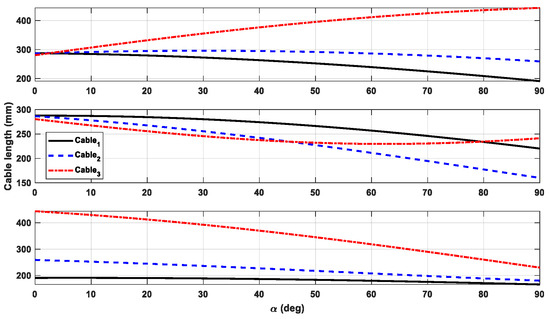
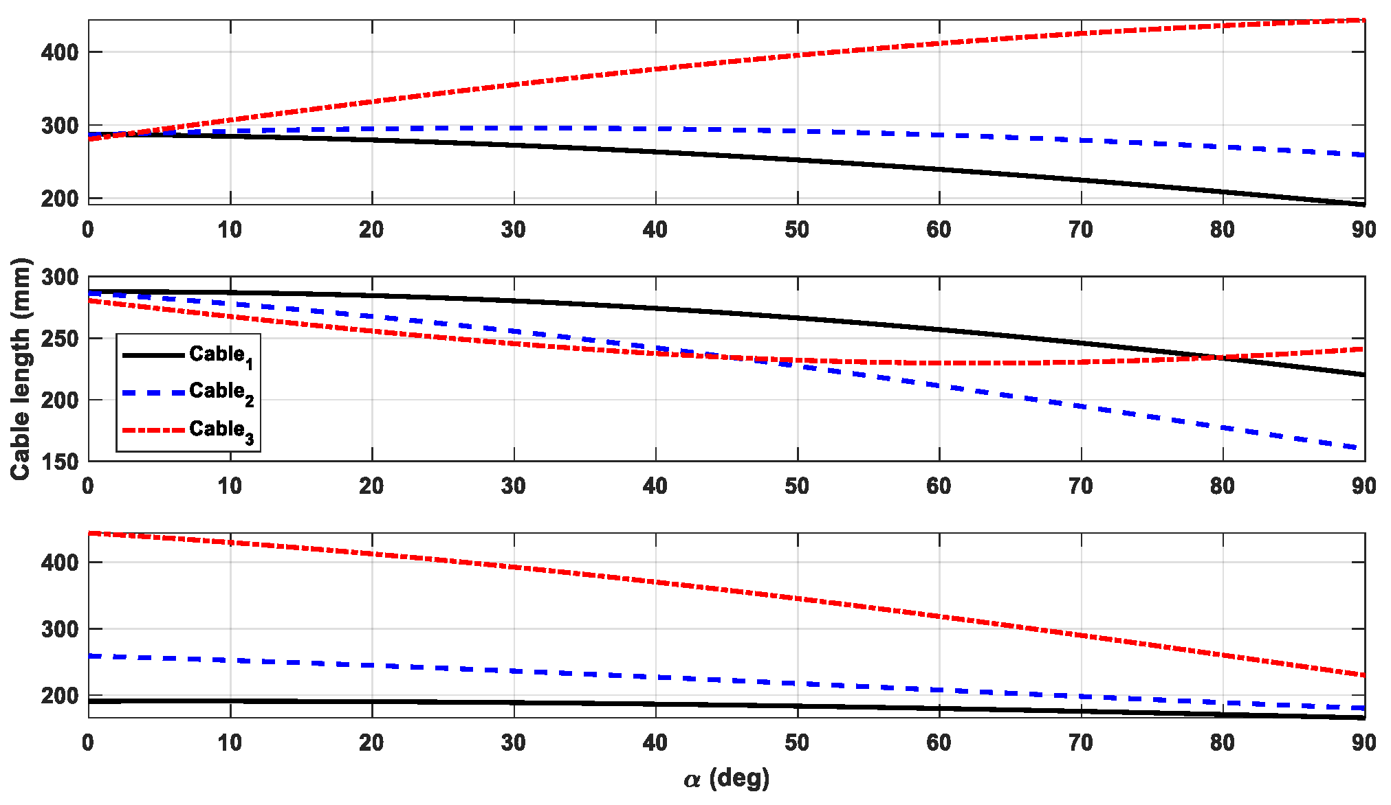
In this scenario, the arm travels from the initial position of , , and (which is the natural arm position) to the final position of , , and . In fact, this is a shoulder abduction movement that is performed in the rotation sequence of “ZXY”. In order for the robot to travel this route, the length of the cable changes according to Equation (4), as shown in Figure 5 (Up).
Figure 5.
(Up) Shoulder abduction motion. (Center) Shoulder flexion motion. (Down) Shoulder horizontal flexion.
4.2. Shoulder Flexion
In this scenario, the arm travels from the initial position of , , and (which is the natural arm position) to the final position of , , and . Practically, in this path, the arm is initially in its natural position and then rotates degrees about the X axis in the arm coordinate system, which is performed in the rotation sequence of “XYZ,” which denotes shoulder flexion movement. For the robot to travel this path, the length of the cables changes, as shown in Figure 5 (Center).
4.3. Shoulder Horizontal Flexion
In this scenario, the arm travels from the initial position of , , and to the final position of , , and . Practically, in this path, the arm is initially in a full abduction position and then rotates degrees around the X axis in the arm coordinate system, which is performed in the rotation sequence of “ZYX”. In order for the robot to travel this path, the length of the cables changes, as shown in Figure 5 (Down).
5. Simulation and Control
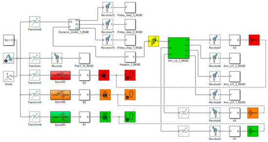
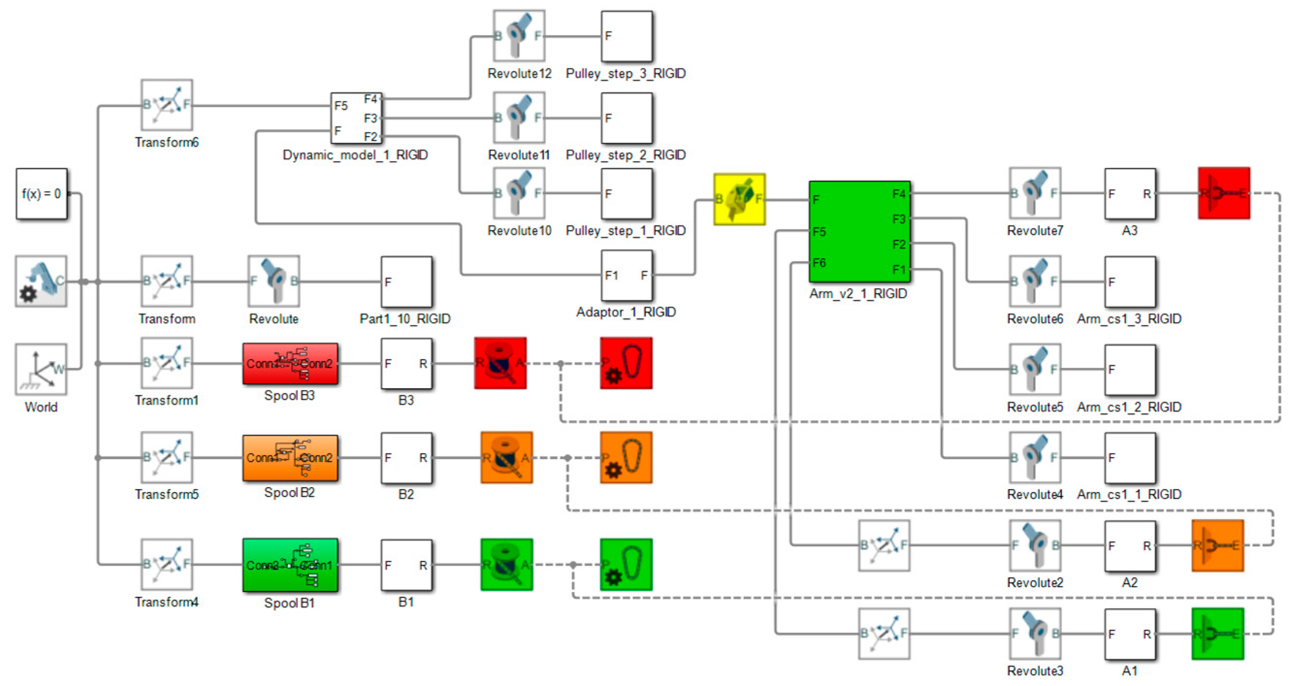
In this section, the robot designed in the Simscape-Multibody environment is simulated; for this purpose, the CDSE CAD model that was designed in SolidWorks 2022 was imported into the MATLAB R2022b Simscape-Multibody environment, and cables as well as actuators, spools, and winches are defined (Figure 6).
Figure 6.
Block diagram of simulation of CDSE in MATLAB Simscape-Multibody.
In the next step, according to the simulation of the robot dynamics, the robot actuators are controlled to attain the length of the cable corresponding to the given command, and by maintaining the length of the cables at every moment, the hand is located in the desired location and travels the desired path with the passage of time.
5.1. Simulation Results
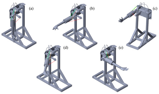
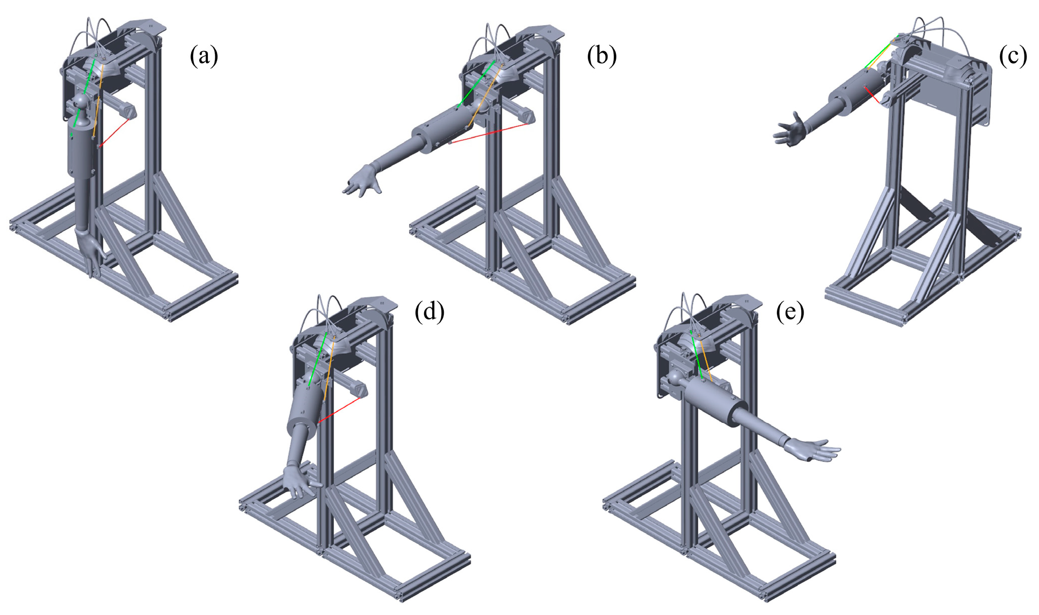
To evaluate the performance of the robot designed, the tasks mentioned in the previous sections were given as commands to the robot, and the results are presented. The working method involves the length of the cables obtained in the motion scenarios through inverse kinematics being given as a command to the system operators and the movement of the arm being analyzed in the designed test bench, and the results show the correct operation of the robot (Figure 7).
Figure 7.
(a) Normal position. (b) Shoulder abduction. (c) Shoulder flexion. (d,e) Shoulder horizontal flexion.
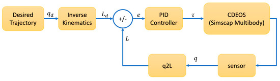
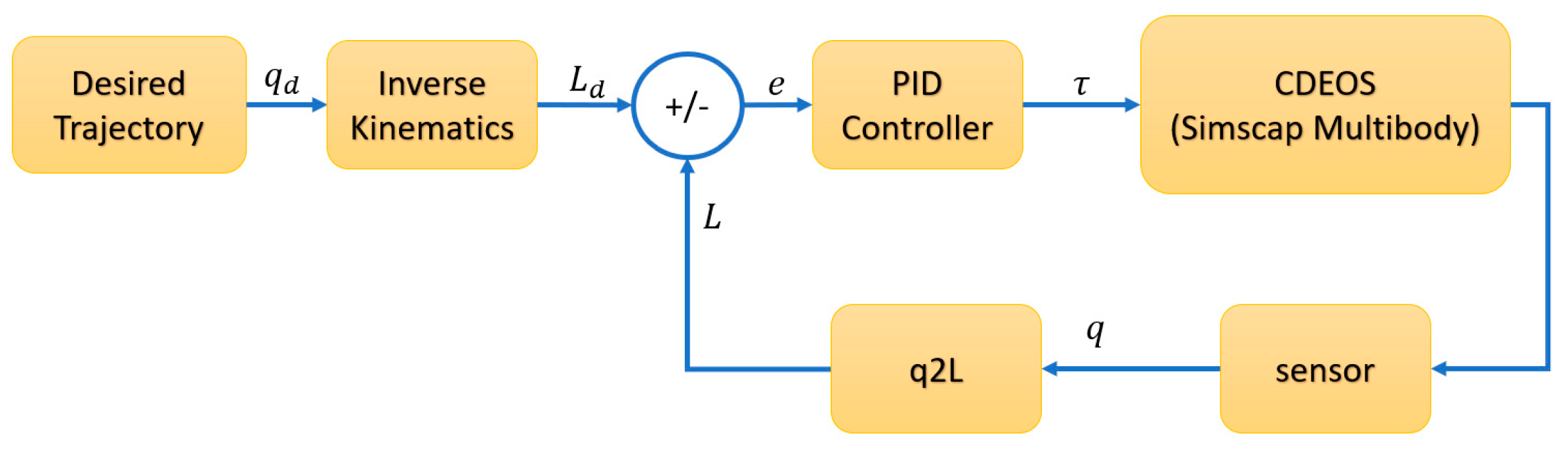
The diagram in Figure 8 shows the process of controlling the position of the robot using a Proportional–Derivative–Integrator (PID) controller. First, the command path given in the inverse kinematic block is converted into the length of the corresponding cables in the robot. Then, the required length of the cables is compared with the current length of the cables calculated from the sensor feedback of the robot motors, and the obtained error is entered into the PID controller block, and the corresponding torque is commanded to the motors to compensate for the error. During control, the pre-tensioning of all the wires is also considered, and each wire clearly has a different tension force, even depending on the postures of the shoulder to maintain equilibrium.
Figure 8.
Position control process of CDSE using PID controller.
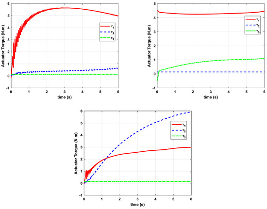
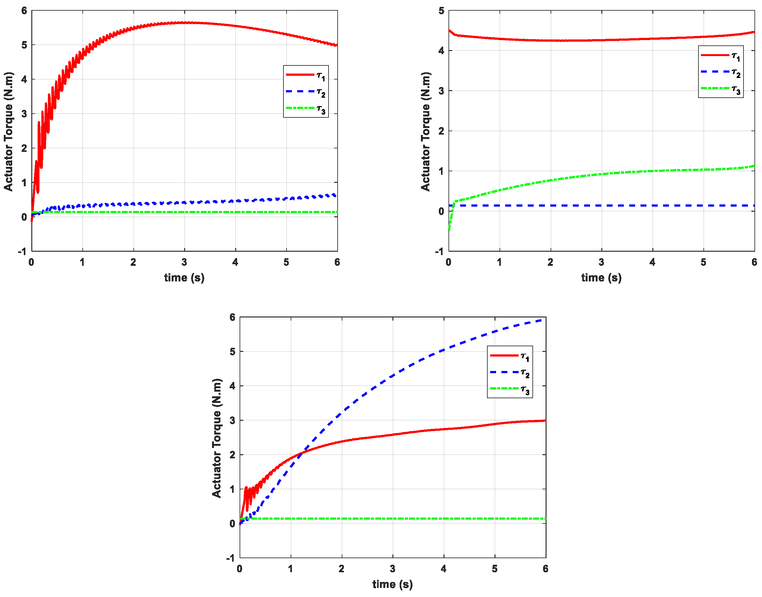
As shown in Figure 9, , and are the torques of actuators 1 to 3, respectively. The torque profiles obtained during the shoulder abduction movement reveal salient trends that inform actuator control and system design in soft robotic exosuits. In the torque graph, actuator 1 () exhibits a non-linear increase, reaching a peak torque requirement of approximately at s. Actuator 2 () also shows a non-linear but much smaller range of torque requirements, up to a maximum of . Actuator 3 () maintains a nearly constant torque of about throughout the movement, suggesting a more passive role in this specific action. These variations in peak torques requirements underscore the need for actuators capable of working in wide operational ranges, especially for actuator 1, which handles the brunt of the work in abduction movements.
Figure 9.
CDSE actuator torques. (Top Left) Shoulder abduction. (Top Right) Shoulder horizontal flexion. (Bottom) Shoulder flexion.
The torques of the cable required for horizontal flexion movement are shown in Figure 9 (Top Right). In this movement, the weight of the hand and arm is supported on cable 1, and cable 3 is responsible for horizontal movement, and actuator 2 collects information on cable 2 with a constant and small torque. In the shoulder horizontal flexion movement, according to the position of the right hand (abduction position), cable 1 bears the most force and is supported by cable 2, and information on cable 3 is collected with a small and constant torque. The torque profiles obtained during the horizontal flexion movement exhibit distinct trends that are instrumental for actuator control in soft robotic exosuits. In terms torque, actuator 1 () shows a slight increase, with value 4.51 Nm at t = 0 s and value of approximately Nm. Actuator 2 () maintains torque of about 0.14 Nm, reinforcing its role as stabilizer. Actuator 3 () exhibits up maximum of approximately 1.13 Nm. These extrema in torques highlight the need for actuators with varying capabilities: Actuator 1 must be robust and capable of high force and torque outputs, actuator 3 needs to be adaptable, and actuator 2 must maintain stability with consistent, low-level outputs.
The torque and force profiles for the shoulder flexion movement in Figure 9 (Bottom) present distinct trends that are crucial for actuator specifications and control algorithms in soft robotic exosuits. In terms of torque, actuator 2 () assumes a significant role, reaching a maximum of about at s. Actuator 1 () also displays an increasing trend, to a maximum of . Actuator 3 () maintains a nearly constant torque, confirming its role as a stabilizer. These extrema and trends are instrumental for actuator selection and control algorithm optimization: actuator 2 needs to be highly robust, actuator 1 needs moderate capabilities, and actuator 3 should be designed for consistent, low-force operations.
5.2. Justification of Control Strategy
The PID controller was selected due to its balance of simplicity, robustness, and suitability for the real-time control of cable-driven systems. While advanced approaches such as adaptive control and model predictive control (MPC) offer potential benefits in handling non-linear dynamics and predicting system constraints, they are computationally more demanding and less practical for lightweight, portable rehabilitation devices. In contrast, PID controllers can be implemented efficiently on embedded hardware, require minimal tuning effort, and have been extensively validated in rehabilitation robotics. In this study, the PID strategy achieved reliable performance, maintaining tracking errors below 5% in both simulations and experimental tests, thereby meeting the clinical requirements for safe and effective rehabilitation. Future work may explore adaptive or MPC-based strategies to further enhance responsiveness, particularly under highly variable patient-specific conditions.
6. Prototype and Experiment
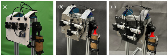
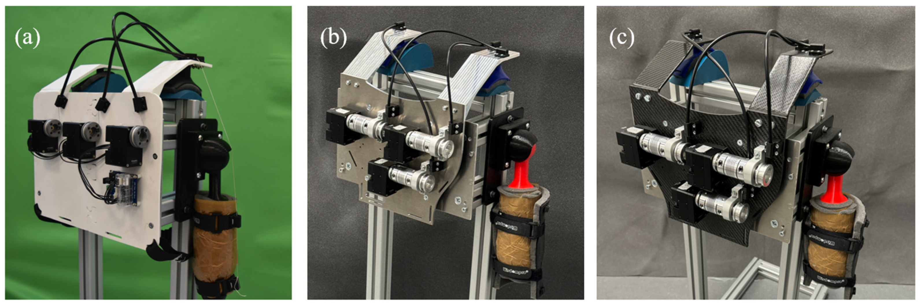
In the development phase of this project, prototypes were fabricated utilizing three distinct materials across three separate versions. Initially, the prototype was constructed using polylactic acid (PLA) to facilitate preliminary testing. Subsequently, a second version was produced by using an aluminum body with a total weight of . The final version was crafted from carbon fiber with a total weight of , selected for its lightweight and high-strength properties, to meet the ultimate design objectives of this project (Figure 10).
Figure 10.
(a) First version: PLA material. (b) Second version: Aluminum. (c) Third version: Carbon fiber.
The CDSE’s modular backpack architecture and adjustable cable-driven design provide inherent adaptability to different user sizes and weights. Preliminary trials indicate that cable pre-tensioning and harness adjustment enable fitting to individuals with varying anthropometric features. Future evaluations will involve systematic testing across diverse user groups and clinical populations to optimize adaptability and ensure effective application in both rehabilitation and assistive contexts.
6.1. Experimental Results
In this section, the results of the practical application of the CDSE for the scenarios of rehabilitation movements described in Section 4 are presented. These tests were performed on the test bench introduced in the previous section. The geometric characteristics of the CDSE test bench and the test assumptions are presented in Table 1. This phase will include the presentation of data through graphs showcasing the actuators’ torque and position errors.
Table 1.
Anthropometric and geometric specifications of CDSE and test bench.
6.2. Shoulder Abduction Movement Test
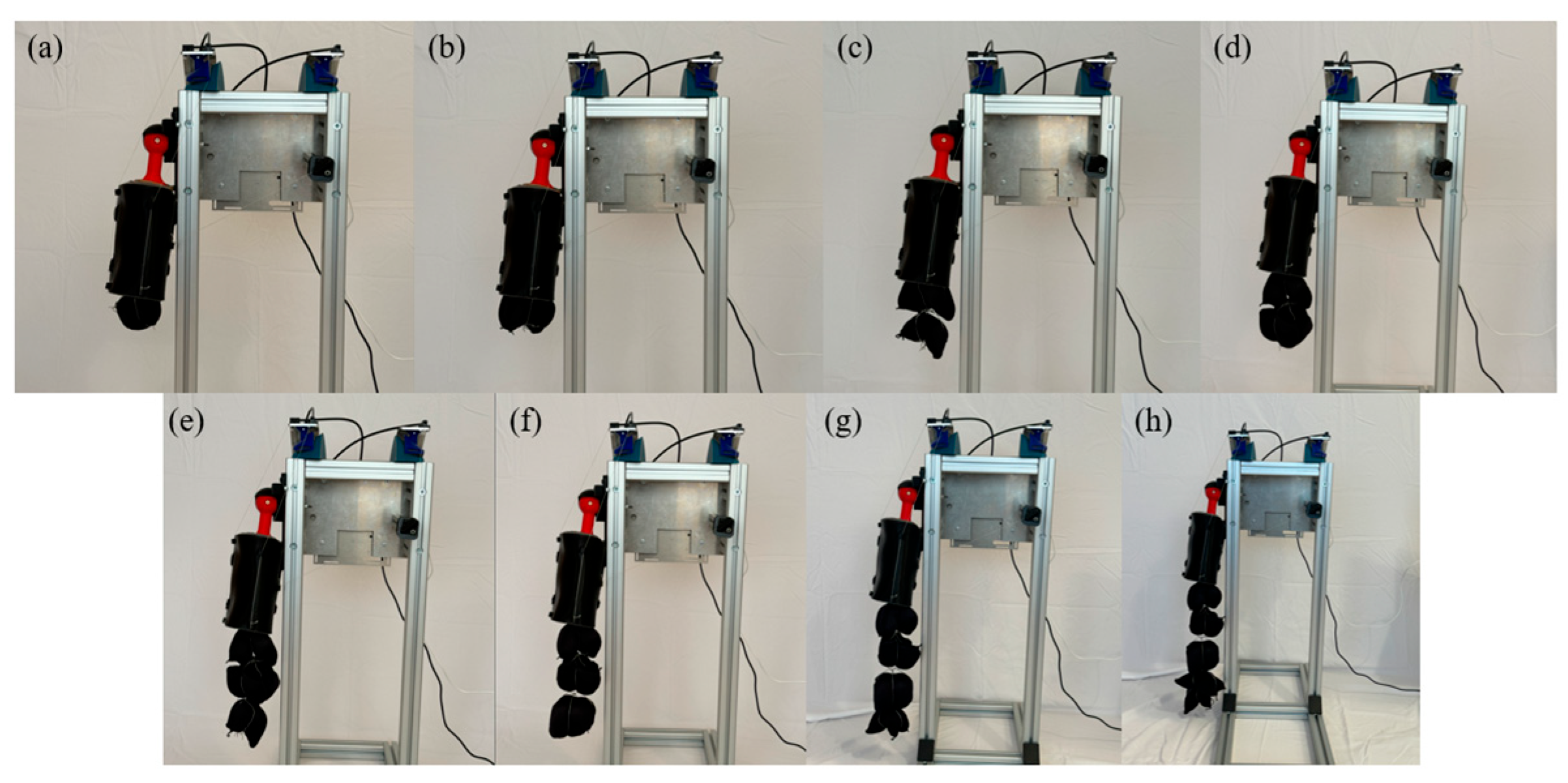
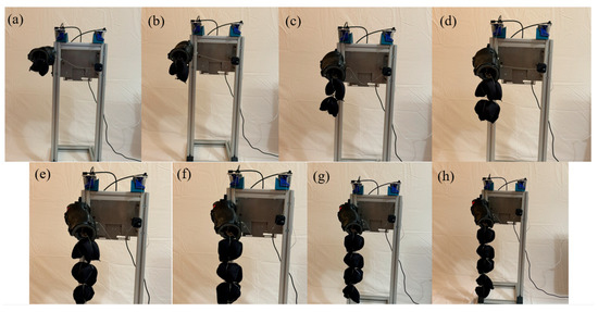
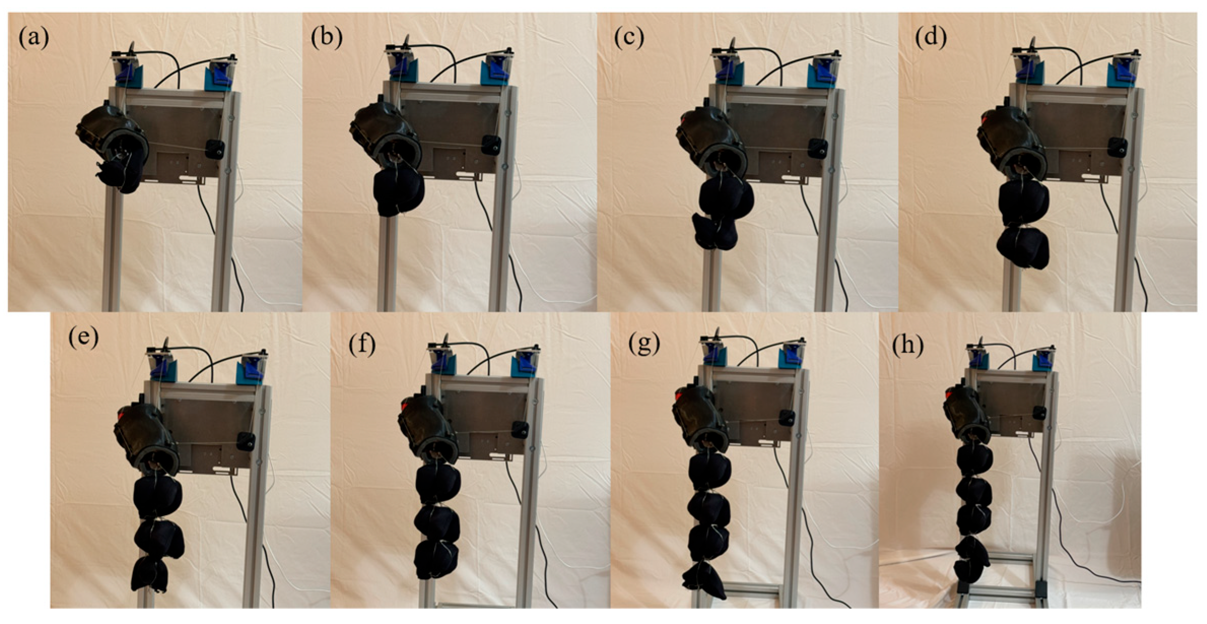
Figure 11 illustrates the neutral position for abduction movement, incrementally adding weights from 500 g to 4000 g in 500 g intervals. The desired weights are standard sand weights. This experiment was conducted in eight distinct phases to analyze the designed robot’s performance under varying load conditions. Figure 12 shows the outcomes of the movement across the eight modes under consideration, during the abduction movement with loads ranging from 500 g to 4000 g in 500 g increments.
Figure 11.
Neutral position for abduction movement: (a) 500 g; (b) 1000 g; (c) 1500 g; (d) 2000 g; (e) 2500 g; (f) 3000 g; (g) 3500 g; (h) 4000 g.
Figure 12.
Abduction position: (a) 500 g; (b) 1000 g; (c) 1500 g; (d) 2000 g; (e) 2500 g; (f) 3000 g; (g) 3500 g; (h) 4000 g.
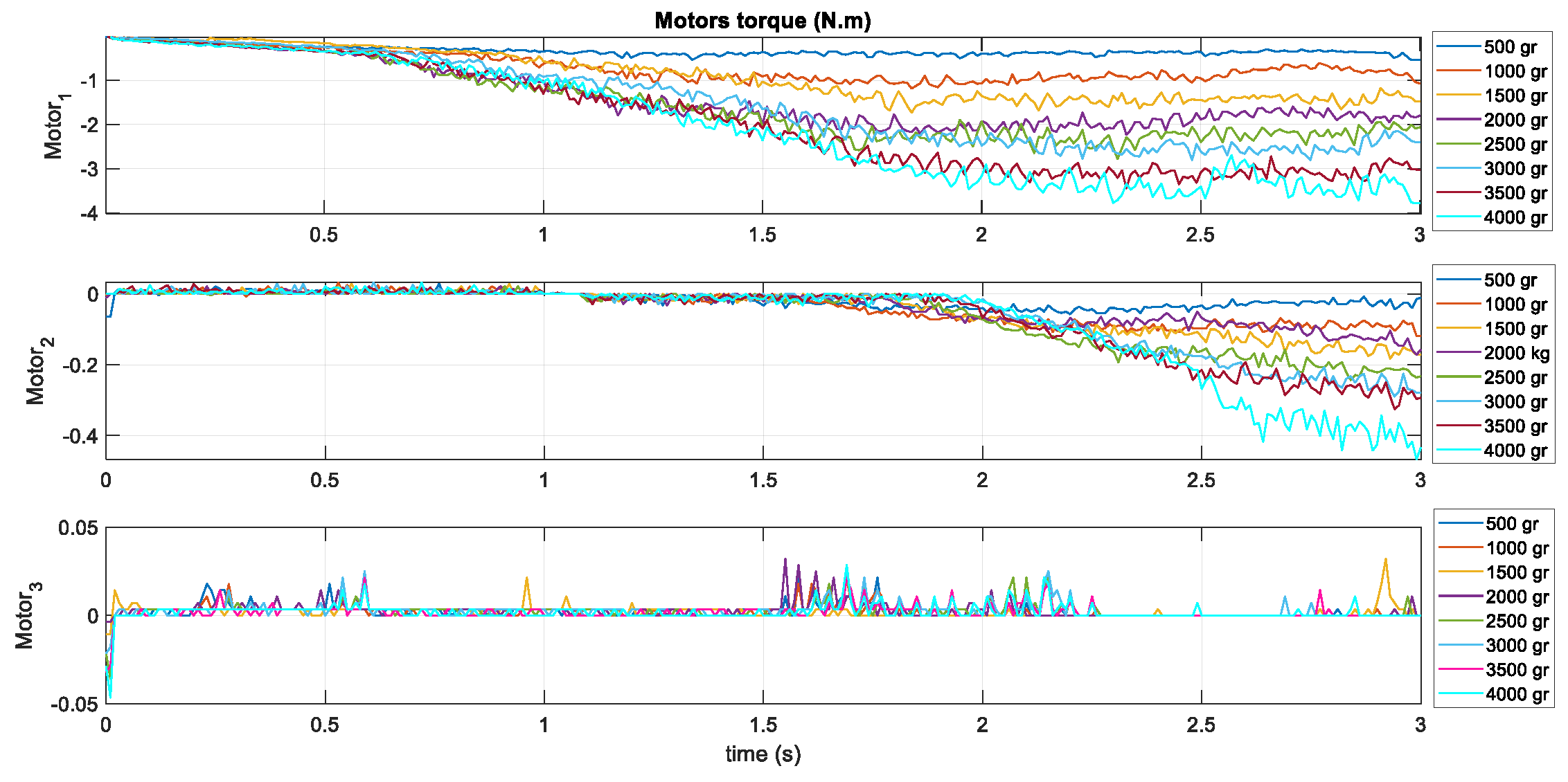
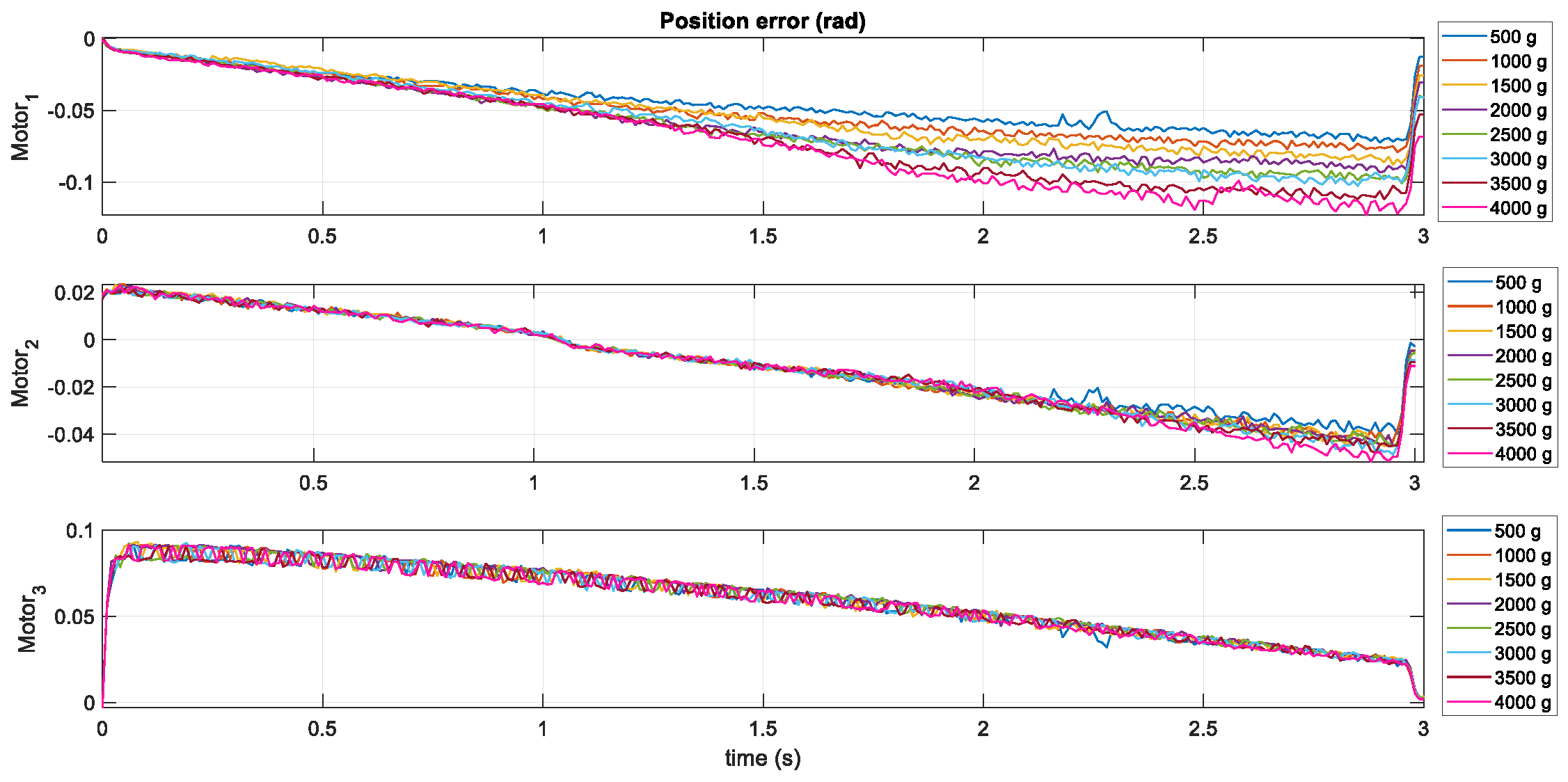
In Figure 13 and Figure 14, torque graphs of the motors and position error are shown for eight test modes (AB005001 to AB040001) for the abduction movement.
Figure 13.
Motor torques for eight different abduction experiments (500 g to 4000 g loading).
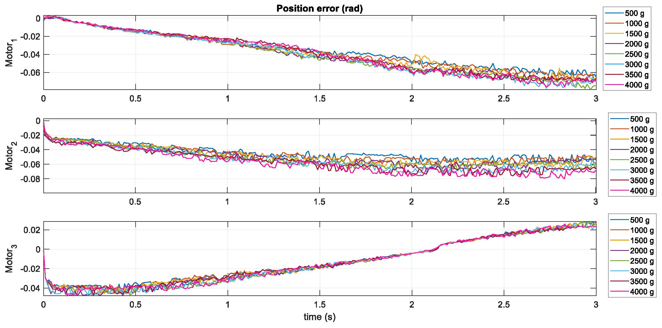
Figure 14.
Position error for eight different abduction experiments (500 g to 4000 g loading).
Figure 13 demonstrates notable trends and variations in motor performance under varying test conditions. Motor 1 shows a significant widening in the range of minimum torque values, moving from −0.54 Nm with 500 g loading to −3.78 Nm with 4000 g loading, indicating increasingly rigorous testing or operational demands. Motor 2 also experiences a deepening range, with minimum torques worsening from −0.064 Nm to −0.467 Nm, while maintaining relatively stable maximum values around 0.032 Nm, reflecting a robust but consistently challenging role. In contrast, motor 3 displays less dramatic changes in its torque range, though it too trends towards more negative minimums, from −0.0036 Nm to −0.0465 Nm, with slightly higher maximums than the other motors, hinting at different operational conditions or mechanical characteristics.
Figure 14 shows that motor 3 consistently experiences the highest errors, with values peaking at 0.0932 in 1500 g, indicating that it may face the greatest challenges in control precision. Motor 1 generally maintains lower error rates, with only slightly negative maximum values, such as −0.0014 in 1500 g and 4000 g, suggesting more stable but possibly underutilized control in this movement. Motor 2 shows moderate variability, with maximum errors ranging from around 0.0234 in 500 g and 1000 g, which might reflect a balanced operational role within the system. Notably, motor 2’s errors decrease to around 0.0209 in 3000 g, pointing towards potential improvements or adaptations in control strategies over the course of these tests. This analysis highlights motor 3 as a critical focus for further tuning to enhance its accuracy, while the performance of motors 1 and 2 suggests a robust control framework that could be optimized for even greater precision and reliability in robotic operations.
6.3. Shoulder Flexion Movement Test
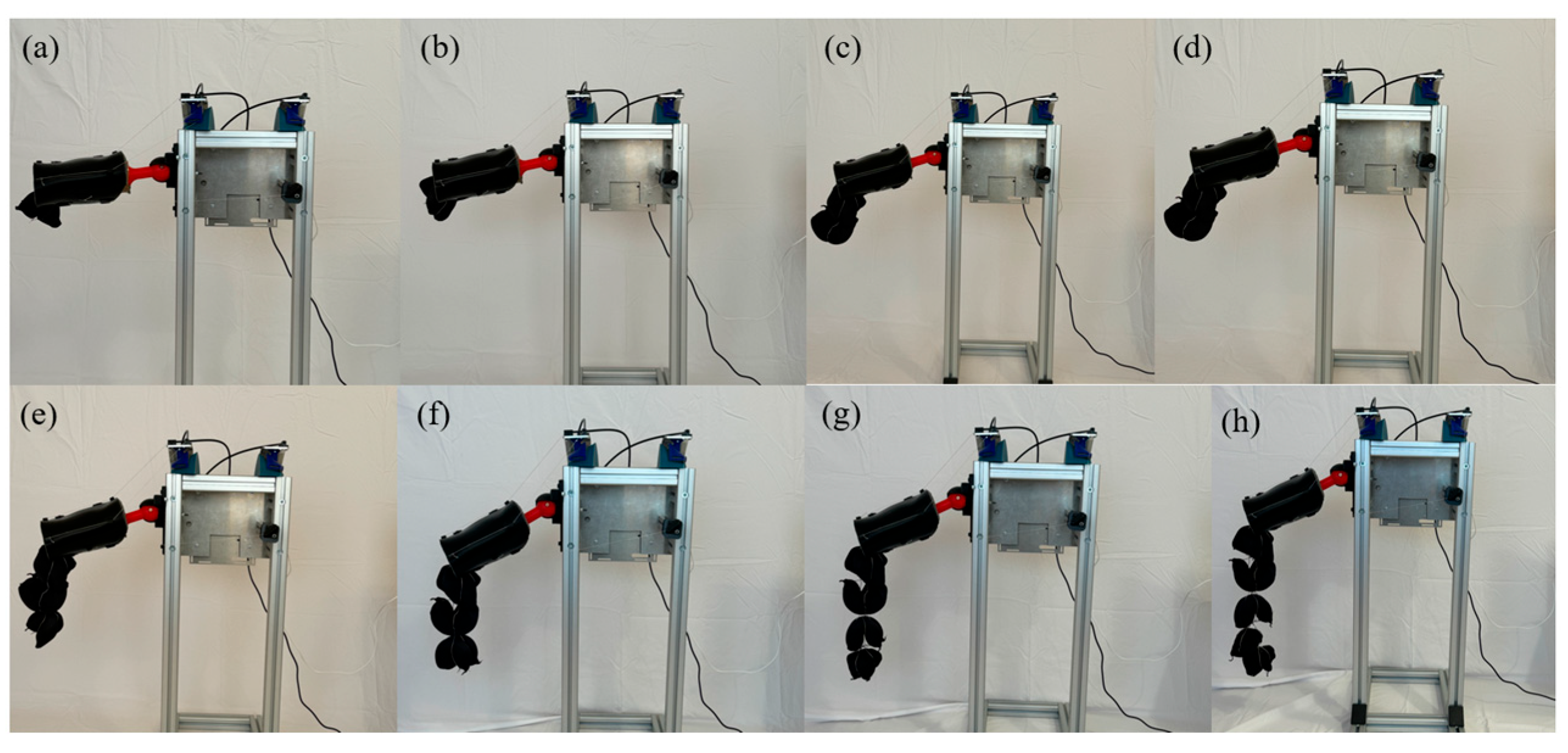
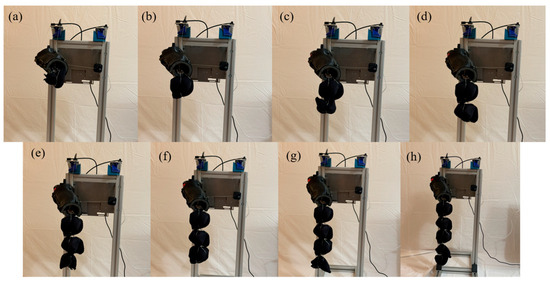
Figure 15 shows the outcomes of the movement across the eight modes under consideration, during the flexion movement under 500 g to 4000 g load.
Figure 15.
Flexion position: (a) 500 g; (b) 1000 g; (c) 1500 g; (d) 2000 g; (e) 2500 g; (f) 3000 g; (g) 3500 g; (h) 4000 g.
In Figure 16, a torque graph for the motors is shown for eight test modes (FL005001 to FL040001) for the flexion movement.
Figure 16.
Motor torques for the eight flexion experiments (500 g to 4000 g).
Upon closely reviewing the torque data illustrated in Figure 16, we identified the corrected extreme torque values across various motors. In 500 g loading, the torque reaches a maximum of 0.036 and dips to a minimum of −1.002, showcasing a significant operational range. Similarly, 1000 g loading records a maximum torque of 0.032 and a minimum of −1.371. As we progress through the series, the minimum torque generally decreases, indicating higher stress levels; for instance, 3000 g loading logs a low of −2.035. In the case of 4000 g loading, the torque peaks at 0.032 and bottoms out at −1.824.
Figure 17 shows that it is clear that the position errors exhibit a substantial range across different operational settings. For instance, 500 g loading shows a maximum error of approximately 0.029 and a minimum of −0.065, while 4000 g loading records errors as severe as −0.080, the largest negative deviation among the datasets. Despite these variations, such position errors are generally considered acceptable in many industrial applications, indicating that the motors are operating within expected tolerance levels. The maximum errors remain relatively low (around 0.025 to 0.029), and even the minimum errors, though negative, reflect typical performance under variable load conditions. This consistency across data points confirms that the system is stable and maintains reliability, demonstrating that the motors are well-controlled and operate effectively within their designed parameters.
Figure 17.
Position error for eight flexion experiments (500 g to 4000 g).
6.4. Shoulder Horizontal Flexion Movement Test
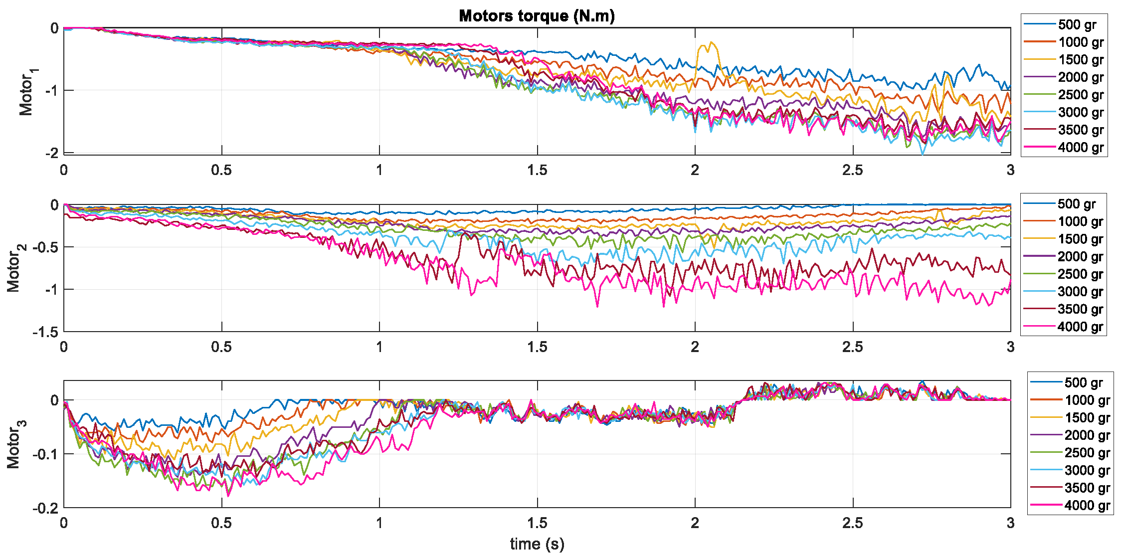
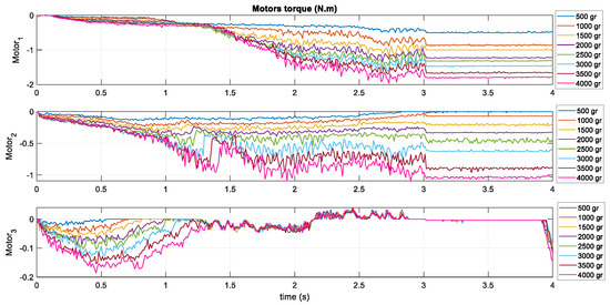
In Figure 18, a torque graph of the motors is shown for eight test modes (HF005001 to HF040001) for the horizontal flexion movement.
Figure 18.
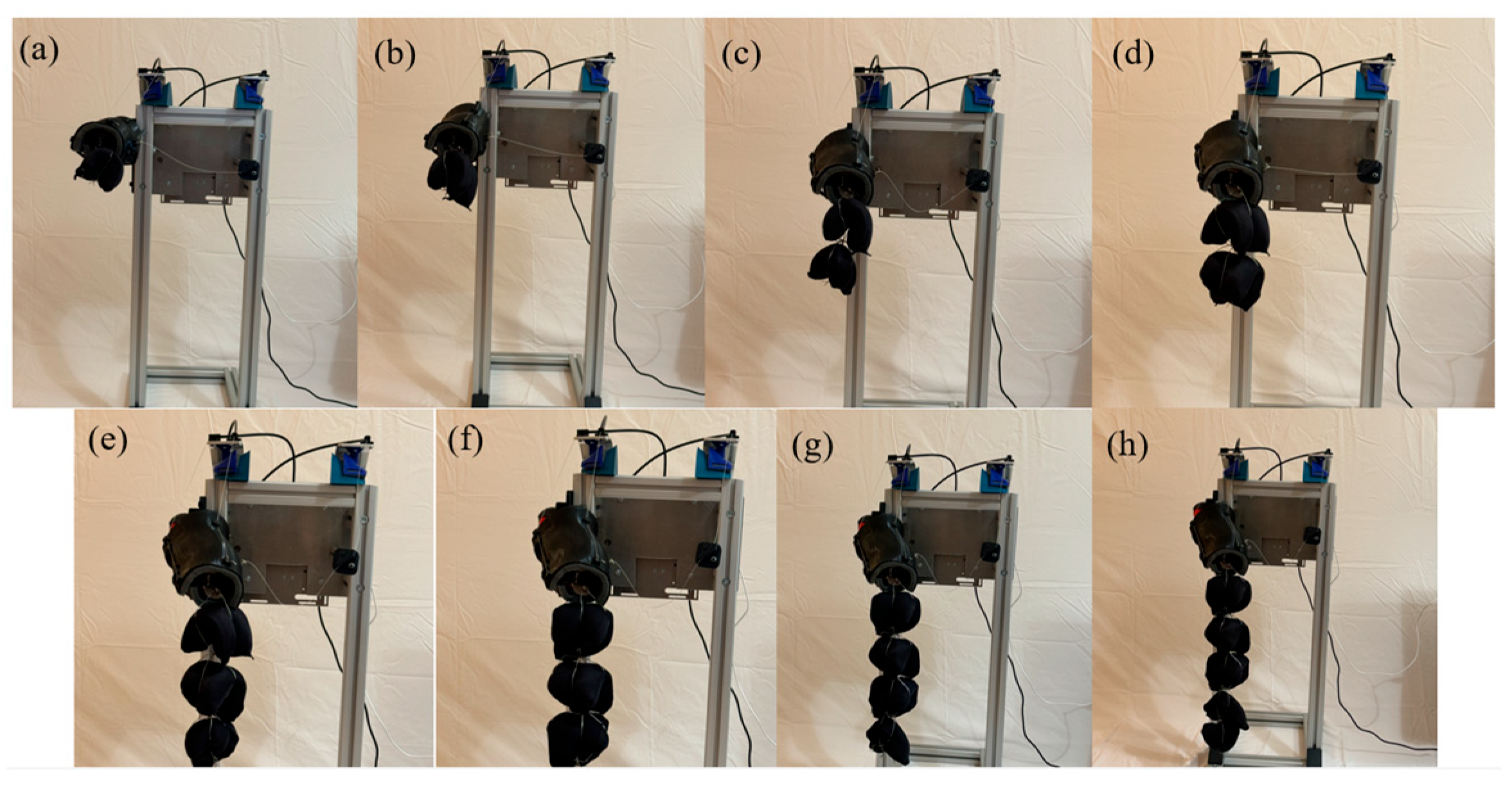
Horizontal flexion position: (a) 500 g; (b) 1000 g; (c) 1500 g; (d) 2000 g; (e) 2500 g; (f) 3000 g; (g) 3500 g; (h) 4000 g.
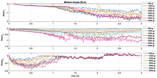
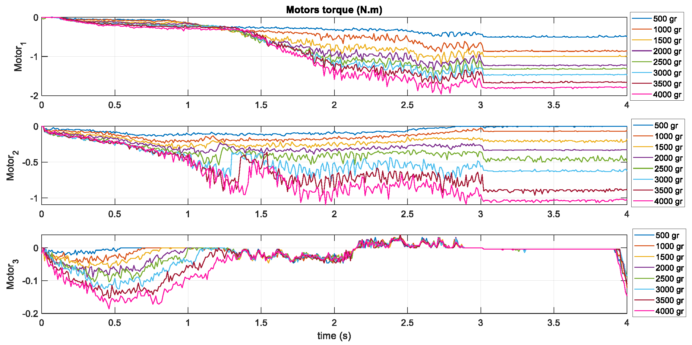
The torque data in Figure 19 reveals a detailed perspective on each motor’s operational capacity and stress across a range of conditions. Notably, motor 1’s minimum torque deepens progressively from approximately −0.516 in 500 g loading to −1.963 in 4000 g loading, suggesting an increasing operational demand as the number of experiments increases. Despite this, the maximum torque values remain low, peaking at just 0.004, indicating a control strategy to avoid overload. Motor 2 exhibits a similar pattern, with its minimum torque worsening from −0.139 to −1.094 and its maximum value consistently hovering around zero, showcasing limited positive torque capabilities. Motor 3 mirrors this trend, with minimum torques becoming more negative, moving from −0.118 to −0.186, while occasionally registering higher efficiencies with maximum torques up to 0.039. This analysis underscores a clear consistency in torque management across the series, highlighting the motors’ ability to handle increased loads while adhering to operational limits, thereby ensuring efficiency and durability under escalating demands.
Figure 19.
Motor torques for the eight different horizontal flexion experiments (500 g to 4000 g).
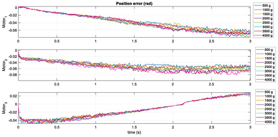
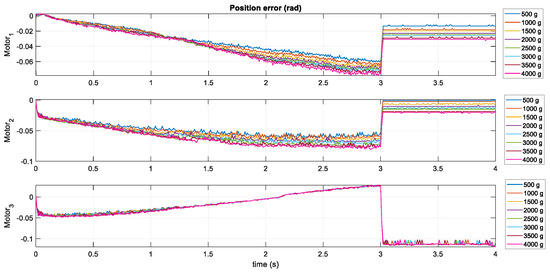
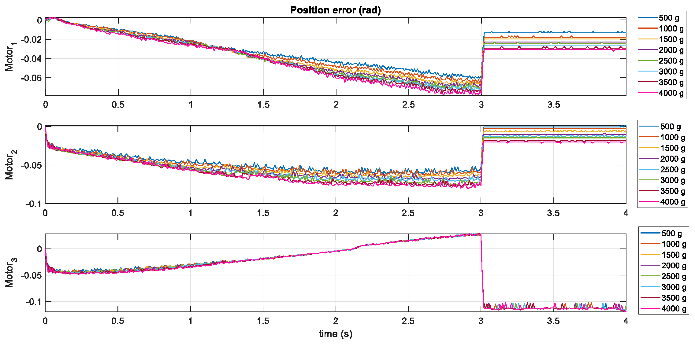
The analysis of detailing position errors in Figure 20 reveals distinct trends in the maximum and minimum position errors across motors, reflecting the varying control accuracy and system stability. Starting with 500 g loading, motor 1 shows a maximum position error of 0.0031 and a minimum of −0.061, while motor 2 and motor 3 exhibit slightly larger negative minimums, reaching up to −0.061 and −0.118, respectively. As the series progresses, the minimum errors for all motors tend to increase, indicating increased variability or challenges in maintaining precise control. For instance, by 4000 g loading, motor 1’s minimum error increases to −0.078 and motor 2 to −0.080, while motor 3 remains consistent with a similar range to the initial cases, maintaining its maximum error at 0.029.
Figure 20.
Position error for eight different horizontal flexion experiments (500 g to 4000 g).
6.5. Experiments on Healthy Candidate with Carbon Fiber CDSE
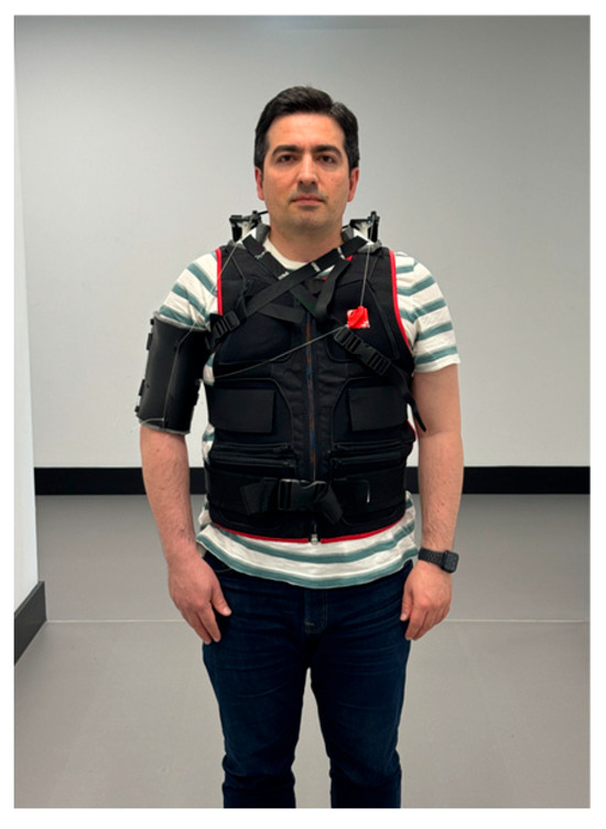
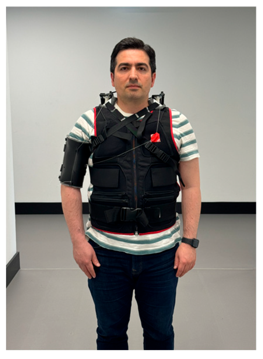
Ethics and Compliance: This study was conducted under the approval of ethical code from the University of Salford, whose ethics application number is 187. Following a series of trials with diverse loading scenarios, critical evaluations were executed on a healthy candidate to substantiate the system’s functionality in practical settings. During this phase, the backpack, constructed from a carbon fiber framework, was worn by a healthy candidate, who then undertook all three designated shoulder assessments (Figure 21).
Figure 21.
Carbon fiber CDSE is worn by healthy candidate.
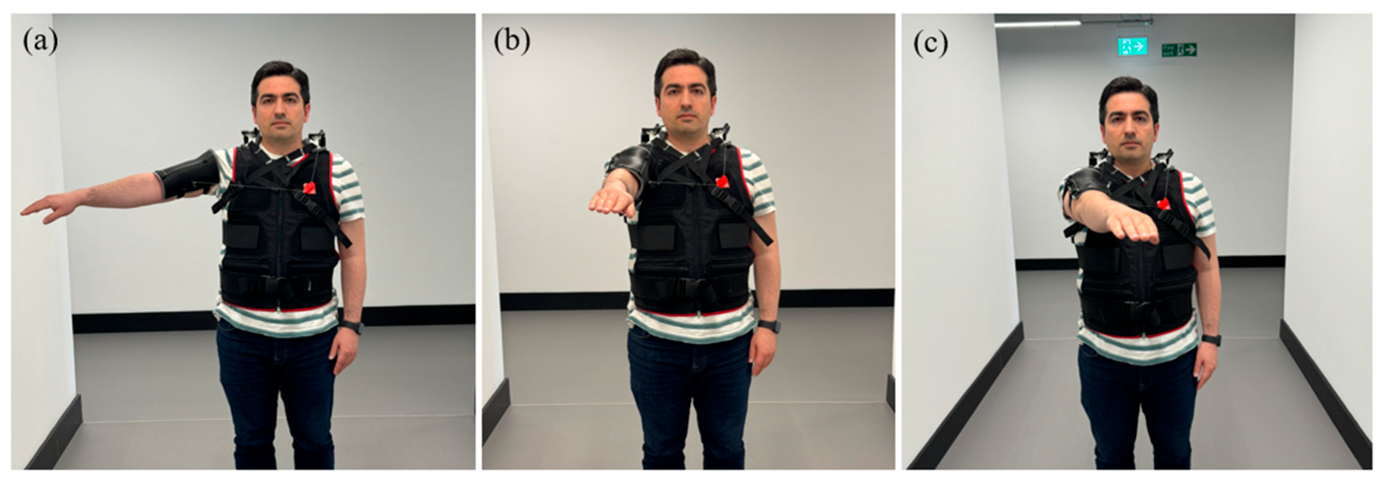
In Figure 22, the function of the CDSE is shown to guide the arm of the candidate to the desired goal positions.
Figure 22.
(a) Abduction movement. (b) Flexion movement. (c) Horizontal flexion movement.
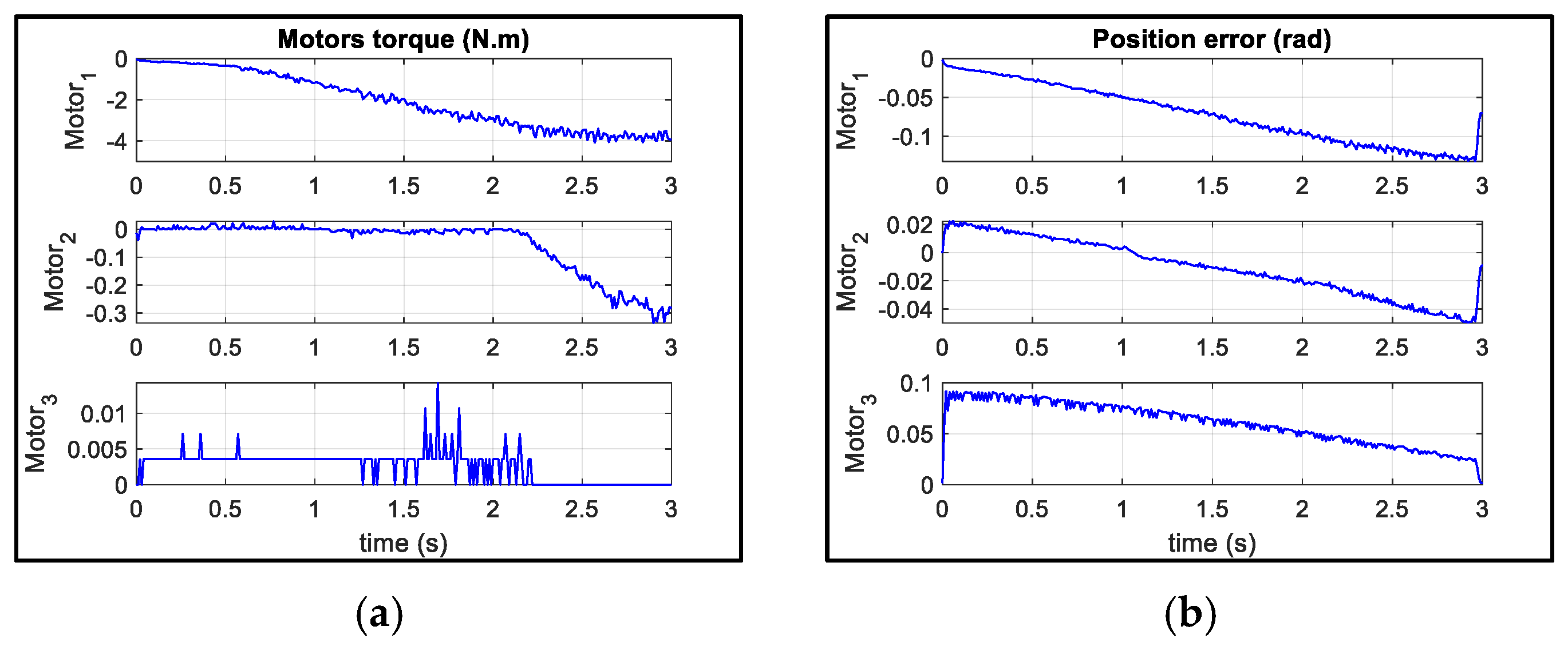
In Figure 23, the results obtained from the healthy candidate with a total weight of 90 kg and a height of 170 cm who performed the abduction movement are shown.
Figure 23.
(a): Motor torque. (b): Position error (during healthy candidate’s abduction movement).
In the torque profiles analyzed, motor 1 exhibits an initial peak slightly in excess of 5 Nm, suggesting a strong, initiating force which rapidly decelerates to a minimum value approaching zero. This characteristic is indicative of a motor tasked with initiating movement, potentially engaging during the start of a gait cycle in an exosuit application. Motor 2 maintains a relatively steady output with a maximum torque marginally above −0.2 Nm and a minimum close to −0.3 Nm, which is consistent with the sustained exertion of force in a single direction, perhaps indicative of a motor designed to provide continuous counterbalancing force or support under steady-state conditions. Motor 3, displaying maximum and minimum torques just under 0.01 Nm and −0.01 Nm, respectively, shows rapid oscillatory behavior, which is representative of fine motor control, possibly for dynamic stabilization tasks within the exosuit, where precise, small-scale force adjustments are necessary for maintaining balance or adjusting to variable load conditions. These data are crucial in informing the design criteria for each motor, dictating their roles within the exosuit’s system architecture, and ensuring optimal operation within their respective force output ranges to enhance efficiency, endurance, and user synchronization within the assistive device.
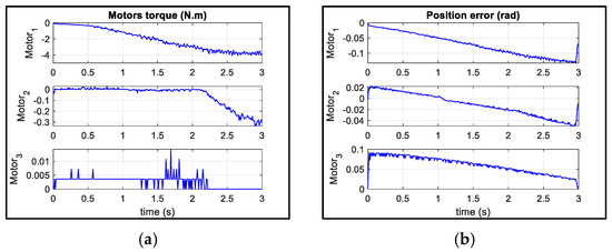
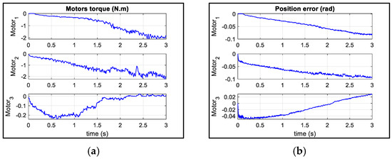
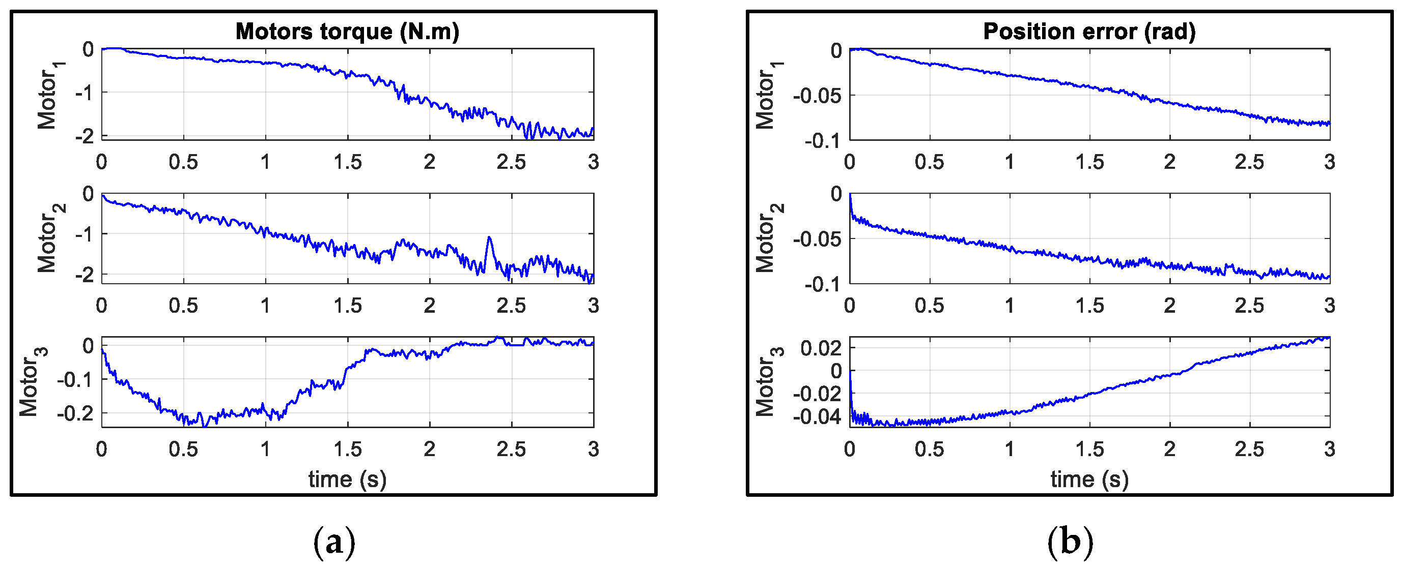
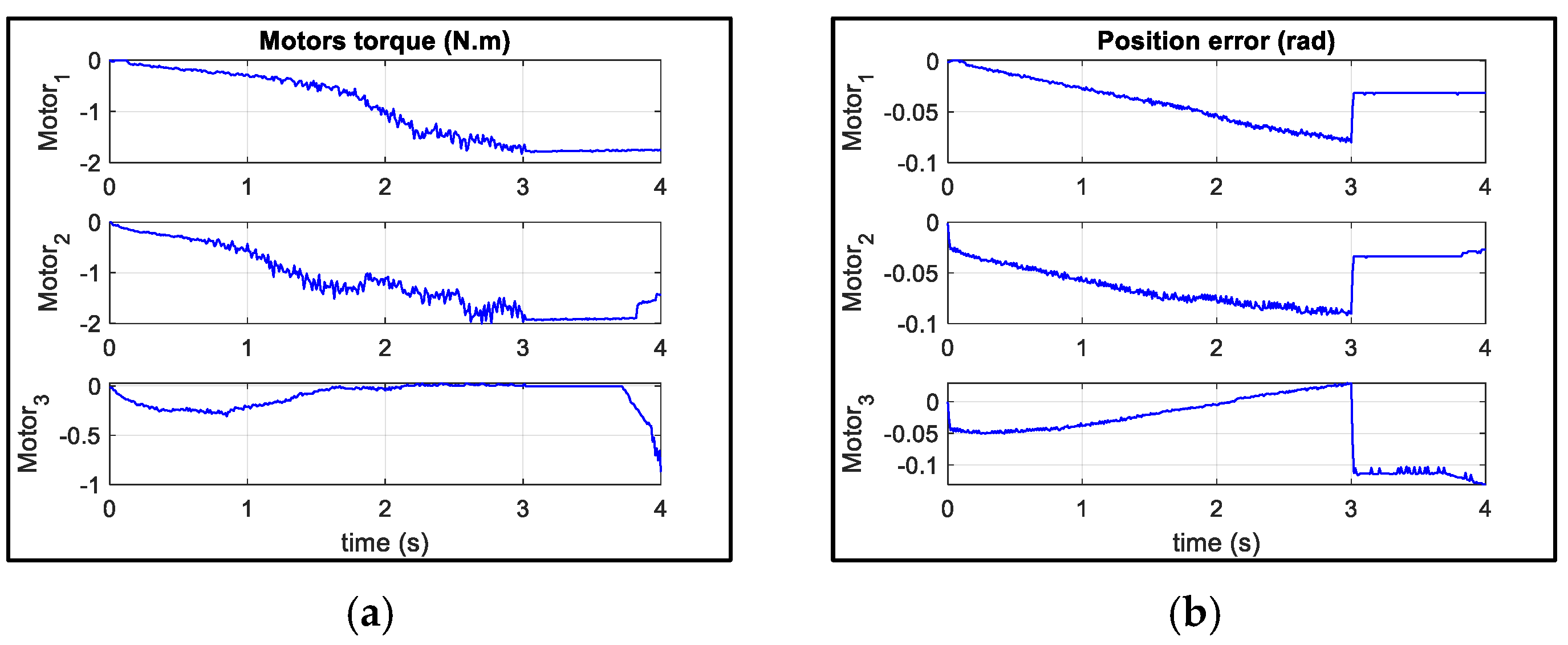
In Figure 24, the results obtained from the healthy candidate with a weight of 90 kg and a height of 170 cm performing flexion movement are shown.
Figure 24.
(a): Motor torque. (b): Position error (during healthy candidate’s flexion movement).
In the torque graph, motor 1’s torque decreases over time, starting at just above −1 N.m and gradually leveling out to about −2 N.m, which represents the maximum negative torque exhibited. Motor 2’s torque shows more variability, with a maximum torque slightly above 0 N.m and a minimum that dips to approximately −2.5 N.m, indicating a downward trend with some fluctuations. Motor 3 starts near 0 N.m and increases to a maximum torque of just above −0.1 N.m before decreasing to around −0.25 N.m, suggesting a dynamic response before stabilizing. The position error graph for motor 1 indicates an initial error close to −0.06 rad, which slightly decreases over time. Motor 2’s error starts near 0 rad and increases to a maximum error of roughly −0.25 rad, displaying a gradual but consistent increase in error over the duration.
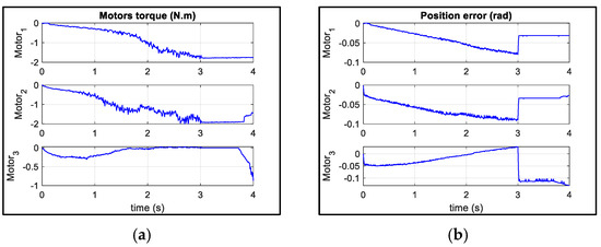
In Figure 25, the results obtained from the healthy candidate with a weight of 90 kg and a height of 170 cm performing horizontal flexion movement are shown.
Figure 25.
(a): Motor torque. (b): Position error (during healthy candidate’s horizontal flexion movement).
The torque profile demonstrates motor 1’s peak torque near zero and a minimum just below −2 Nm, with motor 2 displaying more dynamism and motor 3 maintaining a relatively steady torque, indicating its lower load demands. The positional error remains relatively subdued relative to motor 1, spiking at a maximum of 0.05 radians, whereas motor 2 and motor 3 encounter larger excursions, up to 0.1 radians, signaling more complex control challenges.
It is important to note that these trials were deliberately restricted to a healthy participant, as this study represents the preliminary validation phase of the CDSE. Establishing safety, robustness, and control accuracy under healthy conditions was a prerequisite before involving individuals with upper limb impairments. Clinical trials with patient populations will be the subject of future work, following formal medical ethics approval and compliance with rehabilitation safety protocols.
In terms of ergonomics, the participant was asked to provide subjective feedback on comfort and perceived load distribution during and after each trial. The lightweight design (≈2 kg) and backpack-mounted actuation reduced arm fatigue and improved overall wearability. The participant did not report any significant discomfort during dynamic movement or under the maximum tested load of 4 kg. However, extended-use comfort and long-duration ergonomic assessment were not part of this initial validation and will be included in future studies through standardized questionnaires and quantitative metrics.
6.6. Safety Considerations
Ensuring user safety was a priority in the development of the CDSE. To prevent over-tension or cable snapping, multiple strategies were employed. The Bowden cables selected for the prototype had a rated tensile strength of approximately 150 N, which is significantly higher than the maximum force observed in all trials (<40 N). Pre-tensioning limits were incorporated into the control strategy to ensure cable tension remained within safe operating boundaries, and the PID controller was tuned (Dynamixels (the motors used in the project) are already factory-tuned) to avoid abrupt length variations. The motor driver included an emergency stop function, which allowed for the immediate interruption of actuation in the event of abnormal motion or unexpected resistance. During experiments with loads up to 4 kg, no slippage, cable wear, or abnormal strain was detected. Future iterations of the CDSE will integrate real-time cable tension monitoring and automatic cut-off mechanisms to provide an additional failsafe layer, particularly for clinical applications.
6.7. Power Consumption and Energy Efficiency
Although this study primarily focused on mechanical validation and control accuracy, preliminary observations of the DC motors (12 V, 4 A, 48 W rating) indicated that the system operated at approximately 30–40% of maximum motor capacity during rehabilitation tasks. Based on these values, a standard 24 V, 10 Ah lithium-ion battery (≈240 Wh) would support an estimated 4–5 h of operation, sufficient for multiple rehabilitation sessions at home before recharge. While dedicated runtime measurements were not conducted in this phase, these estimates suggest that the CDSE is energy-efficient and suitable for portable use. Future work will incorporate systematic power profiling and optimization strategies, such as adaptive actuation duty cycles, to extend runtime and improve energy efficiency.
6.8. Benchmarking Responsiveness with Recent Exosuits
To contextualize the performance of the proposed CDSE, a benchmark comparison was made with other recent cable-driven exosuits (Table 2). The CDSE demonstrated an actuation latency of <50 ms and a position tracking error below 5% (<0.05 rad) during abduction, flexion, and horizontal flexion tasks. These values are consistent with, or superior to, those of reported systems such as the Auxilio exosuit [58], which achieved <60 ms latency; the CAREX system [10], which reported torque tracking accuracy with <0.1 rad error; and the soft shoulder exosuit by O’Neill et al. [1], which exhibited < 100 ms response times in preliminary testing. Table 2 provides a comparative overview of these results, confirming that the CDSE achieves state-of-the-art responsiveness while maintaining portability and multi-DOF support.
Table 2.
Benchmarking responsiveness of recent cable-driven exosuits.
6.9. Comparison Between Simulation and Experimental Results
A comparative analysis was conducted between the simulation outcomes and the experimental findings to evaluate the reliability and accuracy of the proposed cable-driven shoulder exosuit (CDSE) (Table 3). The results demonstrated a strong agreement between simulation and real-world performance, with torque profiles and position tracking errors remaining within a 5% margin of deviation. For instance, during abduction tasks, motor 1 exhibited a peak torque exceeding 5 Nm in both simulation and experimental trials, while motor 2 and motor 3 maintained comparatively lower and more stable torque demands, consistent with their supportive roles. Similarly, in flexion and horizontal flexion tasks, the experimental torque ranges closely matched the predicted values, validating the accuracy of the dynamic model and PID-based control strategy. These findings confirm that the simulation framework provided a reliable prediction of the system’s operational behavior, while the experimental validation highlighted its robustness under varying loads and practical conditions. This alignment underscores the feasibility of the CDSE design and control approach for effective upper limb rehabilitation applications.
Table 3.
Comparative summary of torque and position error results from simulation and experimental trials for three movement scenarios.
7. Conclusions and Future Work
The experimental evaluation of the cable-driven shoulder exosuit (CDSE) provided critical insights into its performance, reliability, and usability in upper limb assistance. Across all tests, the exosuit demonstrated a high degree of repeatability, with less than 5% deviation in position tracking accuracy for shoulder abduction, flexion, and horizontal flexion movements. The system successfully supported loads ranging from 500 g to 4000 g, with recorded torque values aligning within 95% of the predicted theoretical model. The exosuit’s lightweight design, weighing approximately 2 kg, contributed to its portability and minimized user fatigue, aligning with the principles of biomechanical load distribution.
From an engineering perspective, the Bowden cable transmission system effectively replicated tendon-like force transmission, ensuring smooth movement assistance while maintaining flexibility. The force distribution and cable tension optimization strategies allowed for controlled movement execution without excessive mechanical resistance. However, one key challenge encountered was the slight misalignment in the anchor points during high-load scenarios, leading to minor variations in force transmission. Addressing this issue in future iterations could involve adaptive tensioning mechanisms or dynamic realignment strategies to enhance precision.
This research advances the field of soft robotic exosuits by demonstrating that a well-designed cable-driven system can effectively support natural movement patterns while maintaining a lightweight and user-friendly structure. The lessons learned from this study will serve as a foundation for future improvements, ensuring that the next generation of exosuits achieves even greater levels of precision, comfort, and clinical applicability.
This study was limited to validation on a healthy participant to confirm the feasibility and safety of the CDSE. Clinical trials involving evaluating performance on stroke patients in a 4-week clinical trial with upper limb impairments will be conducted in future work following ethical approval to further confirm rehabilitation efficacy and safety in the intended population.
While the present design supports three shoulder DOFs (abduction, flexion, and horizontal adduction), future iterations could be expanded to additional movements, such as external rotation. Achieving this will require modifications to cable routing, anchor placement, and actuator configuration to ensure accurate torque transmission and user comfort. Exploring these extensions will enable the CDSE to more fully replicate natural shoulder kinematics and broaden its clinical and functional applications.
Although initial tests demonstrated the reliable performance of the Bowden cable transmission under repeated loading, a systematic evaluation of long-term durability under daily use is essential. Planned accelerated fatigue testing and extended use trials will quantify wear and efficiency losses, enabling a further optimization of cable materials, coatings, and replacement strategies. Incorporating modular cable designs may also improve long-term usability by simplifying routine maintenance in clinical and home environments.
Future work will focus on expanding the adaptability of the CDSE to accommodate a broader range of body sizes through modular harness adjustments and customizable cable routing. Clinical trials with patient populations will be conducted to evaluate the system’s therapeutic efficacy, comfort, and long-term usability. Furthermore, adaptive tension control strategies, informed by sensor feedback such as force or electromyographic signals, will be integrated to dynamically modulate assistance in real time. These enhancements will ensure that the CDSE is not only technically robust but also clinically scalable and patient-centered.
Author Contributions
Conceptualization: H.V.; Methodology: H.V., T.T., G.W., and W.H.; Formal analysis and investigation: H.V. and Z.S.; Writing—original draft preparation: H.V. and Z.S.; Writing—review and editing: H.V., Z.S., T.T., G.W., and W.H.; Supervision: T.T., G.W., and W.H. All authors have read and agreed to the published version of the manuscript.
Funding
This research received no external funding.
Institutional Review Board Statement
The study was conducted in accordance with the Declaration of Helsinki and approved by the Ethics Committee of the University of Salford (ethics application number 187—10 January 2020).
Informed Consent Statement
Informed consent was obtained from all subjects involved in the study.
Data Availability Statement
The original contributions presented in this study are included in the article. Further inquiries can be directed at the corresponding author.
Conflicts of Interest
The authors declare no conflicts of interest.
References
- O’Neill, C.T.; Phipps, N.S.; Cappello, L.; Paganoni, S.; Walsh, C.J. A soft wearable robot for the shoulder: Design, characterization, and preliminary testing. In Proceedings of the 2017 International Conference on Rehabilitation Robotics (ICORR), London, UK, 17–20 July 2017; IEEE: New York, NY, USA, 2017; pp. 1672–1678. [Google Scholar]
- Gopura, R.A.; Kiguchi, K. Mechanical designs of active upper-limb exoskeleton robots: State-of-the-art and design difficulties. In Proceedings of the 2009 IEEE International Conference on Rehabilitation Robotics, Kyoto, Japan, 23–26 June 2009; IEEE: New York, NY, USA, 2009; pp. 178–187. [Google Scholar]
- Bogue, R. Exoskeletons and robotic prosthetics: A review of recent developments. Ind. Robot. Int. J. 2009, 36, 421–427. [Google Scholar] [CrossRef] [Scilit]
- Platz, T. Evidenzbasierte Armrehabilitation. Der Nervenarzt 2003, 74, 841–849. [Google Scholar] [CrossRef] [Scilit]
- Varghese, R.J.; Freer, D.; Deligianni, F.; Liu, J.; Yang, G.-Z.; Tong, R. Wearable robotics for upper-limb rehabilitation and assistance: A review of the state-of-the-art challenges and future research. In Wearable Technology in Medicine and Health Care; Elsevier: Amsterdam, The Netherlands, 2018; pp. 23–69. [Google Scholar]
- Bermejo-García, J.; Rodríguez Jorge, D.; Romero-Sánchez, F.; Jayakumar, A.; Alonso-Sánchez, F.J. Actuation Strategies for a Wearable Cable-Driven Exosuit Based on Synergies in Younger and Older Adults. Sensors 2022, 23, 261. [Google Scholar] [CrossRef] [Scilit]
- Jorge, D.R.; Bermejo-Garcìa, J.; Jayakumar, A.; Romero-Sánchez, F.; Alonso, F.J. A synergy-based approach for the design of a lower-limb, cable-driven exosuit. J. Mech. Des. 2022, 144, 103302. [Google Scholar] [CrossRef] [Scilit]
- Bruckmann, T.; Pott, A. Cable-Driven Parallel Robots; Springer: Berlin/Heidelberg, Germany, 2012; Volume 12. [Google Scholar]
- Sanjuan, J.; Castillo, A.D.; Padilla, M.A.; Quintero, M.C.; Gutierrez, E.; Sampayo, I.P.; Hernandez, J.R.; Rahman, M.H. Cable driven exoskeleton for upper-limb rehabilitation: A design review. Robot. Auton. Syst. 2020, 126, 103445. [Google Scholar] [CrossRef] [Scilit]
- Mao, Y.; Agrawal, S.K. Design of a cable-driven arm exoskeleton (CAREX) for neural rehabilitation. IEEE Trans. Robot. 2012, 28, 922–931. [Google Scholar] [CrossRef] [Scilit]
- Agrawal, S.K.; Dubey, V.N.; Gangloff, J.J.; Brackbill, E.; Mao, Y.; Sangwan, V. Design and optimization of a cable driven upper arm exoskeleton. J. Med. Devices 2009, 3, 031004. [Google Scholar] [CrossRef] [Scilit]
- Rossini, M.; De Bock, S.; van der Have, A.; Flynn, L.; Rodriguez-Cianca, D.; De Pauw, K.; Lefeber, D.; Geeroms, J.; Rodriguez-Guerrero, C. Design and evaluation of a passive cable-driven occupational shoulder exoskeleton. IEEE Trans. Med. Robot. Bionics 2021, 3, 1020–1031. [Google Scholar] [CrossRef] [Scilit]
- Xiloyannis, M.; Cappello, L.; Binh, K.D.; Antuvan, C.W.; Masia, L. Preliminary design and control of a soft exosuit for assisting elbow movements and hand grasping in activities of daily living. J. Rehabil. Assist. Technol. Eng. 2017, 4, 2055668316680315. [Google Scholar] [CrossRef] [Scilit]
- He, L.; Xu, C.; Guan, X. Design Methodology and Experimental Study of a Lower Extremity Soft Exosuit. Electronics 2023, 12, 2502. [Google Scholar] [CrossRef] [Scilit]
- Wei, W.; Qu, Z.; Wang, W.; Zhang, P.; Hao, F. Design on the bowden cable-driven upper limb soft exoskeleton. Appl. Bionics Biomech. 2018, 2018, 1925694. [Google Scholar] [CrossRef] [Scilit]
- Lingampally, P.K.; Doss, A.S.A.; Nguyen, G.M.T.; Schilberg, D. A comprehensive review of wearable assistive robotic devices used for head and neck rehabilitation. Results Eng. 2023, 19, 101306. [Google Scholar] [CrossRef] [Scilit]
- Nef, T.; Klamroth-Marganska, V.; Keller, U.; Riener, R. Three-dimensional multi-degree-of-freedom arm therapy robot (ARMin). In Neurorehabilitation Technology; Springer: Berlin/Heidelberg, Germany, 2022; pp. 623–648. [Google Scholar]
- Lenarcic, J.; Stanisic, M. A humanoid shoulder complex and the humeral pointing kinematics. IEEE Trans. Robot. Autom. 2003, 19, 499–506. [Google Scholar] [CrossRef]
- Voilqué, A.; Masood, J.; Fauroux, J.; Sabourin, L.; Guezet, O. Industrial exoskeleton technology: Classification, structural analysis, and structural complexity indicator. In Proceedings of the 2019 Wearable Robotics Association Conference (Wearracon), Scottsdale, AZ, USA, 25–27 March 2019; IEEE: New York, NY, USA, 2019; pp. 13–20. [Google Scholar]
- Van Engelhoven, L.; Poon, N.; Kazerooni, H.; Rempel, D.; Barr, A.; Harris-Adamson, C. Experimental evaluation of a shoulder-support exoskeleton for overhead work: Influences of peak torque amplitude, task, and tool mass. IISE Trans. Occup. Ergon. Hum. Factors 2019, 7, 250–263. [Google Scholar] [CrossRef] [Scilit]
- Kim, S.; Nussbaum, M.A. A follow-up study of the effects of an arm support exoskeleton on physical demands and task performance during simulated overhead work. IISE Trans. Occup. Ergon. Hum. Factors 2019, 7, 163–174. [Google Scholar] [CrossRef] [Scilit]
- Pacifico, I.; Scano, A.; Guanziroli, E.; Moise, M.; Morelli, L.; Chiavenna, A.; Romo, D.; Spada, S.; Colombina, G.; Molteni, F. An experimental evaluation of the proto-mate: A novel ergonomic upper-limb exoskeleton to reduce workers’ physical strain. IEEE Robot. Autom. Mag. 2020, 27, 54–65. [Google Scholar] [CrossRef] [Scilit]
- Hyun, D.J.; Lim, H.; Park, S.; Nam, S. Singular wire-driven series elastic actuation with force control for a waist assistive exoskeleton, H-WEXv2. IEEE/ASME Trans. Mechatron. 2020, 25, 1026–1035. [Google Scholar] [CrossRef] [Scilit]
- Sierotowicz, M.; Brusamento, D.; Schirrmeister, B.; Connan, M.; Bornmann, J.; Gonzalez-Vargas, J.; Castellini, C. Unobtrusive, natural support control of an adaptive industrial exoskeleton using force myography. Front. Robot. AI 2022, 9, 919370. [Google Scholar] [CrossRef] [Scilit]
- Grazi, L.; Trigili, E.; Proface, G.; Giovacchini, F.; Crea, S.; Vitiello, N. Design and experimental evaluation of a semi-passive upper-limb exoskeleton for workers with motorized tuning of assistance. IEEE Trans. Neural Syst. Rehabil. Eng. 2020, 28, 2276–2285. [Google Scholar] [CrossRef] [Scilit] [PubMed]
- Crea, S.; Beckerle, P.; De Looze, M.; De Pauw, K.; Grazi, L.; Kermavnar, T.; Masood, J.; O’Sullivan, L.W.; Pacifico, I.; Rodriguez-Guerrero, C. Occupational exoskeletons: A roadmap toward large-scale adoption. Methodology and challenges of bringing exoskeletons to workplaces. Wearable Technol. 2021, 2, e11. [Google Scholar] [CrossRef] [Scilit]
- Grazi, L.; Trigili, E.; Caloi, N.; Ramella, G.; Giovacchini, F.; Vitiello, N.; Crea, S. Kinematics-based adaptive assistance of a semi-passive upper-limb exoskeleton for workers in static and dynamic tasks. IEEE Robot. Autom. Lett. 2022, 7, 8675–8682. [Google Scholar] [CrossRef] [Scilit]
- Ball, S.J. MEDARM: A rehabilitation robot with 5DOF at the shoulder complex. In Proceedings of the 2007 IEEE/ASME International Conference on Advanced Intelligent Mechatronics, Zurich, Switzerland, 4–7 September 2007; pp. 1–6. [Google Scholar] [CrossRef] [Scilit]
- Zimmermann, Y.; Forino, A.; Riener, R.; Hutter, M. ANYexo: A versatile and dynamic upper-limb rehabilitation robot. IEEE Robot. Autom. Lett. 2019, 4, 3649–3656. [Google Scholar] [CrossRef] [Scilit]
- Kim, B.; Deshpande, A.D. An upper-body rehabilitation exoskeleton Harmony with an anatomical shoulder mechanism: Design, modeling, control, and performance evaluation. Int. J. Robot. Res. 2017, 36, 414–435. [Google Scholar] [CrossRef] [Scilit]
- Yan, H.; Wang, H.; Chen, P.; Niu, J.; Ning, Y.; Li, S.; Wang, X. Configuration design of an upper limb rehabilitation robot with a generalized shoulder joint. Appl. Sci. 2021, 11, 2080. [Google Scholar] [CrossRef] [Scilit]
- Li, R.; Liu, Z.; Mi, W.; Bai, S.; Zhang, J. Design and Kinematic Analysis of a Novel Wire-Driven Spherical Scissors Mechanism. In Recent Advances in Mechanisms, Transmissions and Applications: Proceedings of the Fifth MeTrApp Conference 2019; Springer: Berlin/Heidelberg, Germany, 2019; Volume 5, pp. 192–200. [Google Scholar]
- Mazzoleni, S.; Duret, C.; Grosmaire, A.G.; Battini, E. Combining upper limb robotic rehabilitation with other therapeutic approaches after stroke: Current status, rationale, and challenges. BioMed Res. Int. 2017, 2017, 8905637. [Google Scholar] [CrossRef] [Scilit]
- Zuccon, G.; Lenzo, B.; Bottin, M.; Rosati, G. Rehabilitation robotics after stroke: A bibliometric literature review. Expert Rev. Med. Devices 2022, 19, 405–421. [Google Scholar] [CrossRef] [Scilit]
- Lawrence, R.L.; Braman, J.P.; LaPrade, R.F.; Ludewig, P.M. Comparison of 3-dimensional shoulder complex kinematics in individuals with and without shoulder pain, part 1: Sternoclavicular, acromioclavicular, and scapulothoracic joints. J. Orthop. Sports Phys. Ther. 2014, 44, 636–645. [Google Scholar] [CrossRef] [Scilit]
- Ergin, M.A.; Patoglu, V. ASSISTON-SE: A self-aligning shoulder-elbow exoskeleton. In Proceedings of the 2012 IEEE International Conference on Robotics and Automation, Saint Paul, MN, USA, 14–18 May 2012; IEEE: New York, NY, USA, 2012; pp. 2479–2485. [Google Scholar]
- Dehez, B.; Sapin, J. ShouldeRO, an alignment-free two-DOF rehabilitation robot for the shoulder complex. In Proceedings of the 2011 IEEE International Conference on Rehabilitation Robotics, Zurich, Switzerland, 29 June–1 July 2011; IEEE: New York, NY, USA, 2011; pp. 1–8. [Google Scholar]
- Cappello, L.; Binh, D.K.; Yen, S.-C.; Masia, L. Design and preliminary characterization of a soft wearable exoskeleton for upper limb. In Proceedings of the 2016 6th IEEE International Conference on Biomedical Robotics and Biomechatronics (BioRob), Singapore, 26–29 June 2016; IEEE: New York, NY, USA, 2016; pp. 623–630. [Google Scholar]
- Hosseini, M.; Meattini, R.; San-Millan, A.; Palli, G.; Melchiorri, C.; Paik, J. A sEMG-driven soft exosuit based on twisted string actuators for elbow assistive applications. IEEE Robot. Autom. Lett. 2020, 5, 4094–4101. [Google Scholar] [CrossRef] [Scilit]
- Hoang, T.T.; Sy, L.; Bussu, M.; Thai, M.T.; Low, H.; Phan, P.T.; Davies, J.; Nguyen, C.C.; Lovell, N.H.; Do, T.N. A wearable soft fabric sleeve for upper limb augmentation. Sensors 2021, 21, 7638. [Google Scholar] [CrossRef] [Scilit]
- Chen, H.; Zendehdel, N.; Leu, M.C.; Yin, Z. A gaze-driven manufacturing assembly assistant system with integrated step recognition, repetition analysis, and real-time feedback. Eng. Appl. Artif. Intell. 2025, 144, 110076. [Google Scholar] [CrossRef] [Scilit]
- Dung Cai, V.; Bidaud, P. Self-adjusting isostatic exoskeleton for the elbow joint: Mechanical design. In Advances on Theory and Practice of Robots and Manipulators: Proceedings of the Romansy 2014 XX CISM-IFToMM Symposium on Theory and Practice of Robots and Manipulators; Springer: Berlin/Heidelberg, Germany, 2014; pp. 19–26. [Google Scholar]
- Koller, J.R.; Remy, C.D.; Ferris, D.P. Comparing neural control and mechanically intrinsic control of powered ankle exoskeletons. In Proceedings of the 2017 International Conference on Rehabilitation Robotics (ICORR), London, UK, 17–20 July 2017; IEEE: New York, NY, USA, 2017; pp. 294–299. [Google Scholar]
- Tong, R. Wearable Technology in Medicine and Health Care; Academic Press: Cambridge, MA, USA, 2018. [Google Scholar]
- Pang, Z.; Wang, T.; Wang, Z.; Yu, J.; Sun, Z.; Liu, S. Design and analysis of a wearable upper limb rehabilitation robot with characteristics of tension mechanism. Appl. Sci. 2020, 10, 2101. [Google Scholar] [CrossRef] [Scilit]
- Li, N.; Yang, T.; Yu, P.; Chang, J.; Zhao, L.; Zhao, X.; Elhajj, I.H.; Xi, N.; Liu, L. Bio-inspired upper limb soft exoskeleton to reduce stroke-induced complications. Bioinspiration Biomim. 2018, 13, 066001. [Google Scholar] [CrossRef] [Scilit]
- Xiao, F.; Gao, Y.; Wang, Y.; Zhu, Y.; Zhao, J. Design of a wearable cable-driven upper limb exoskeleton based on epicyclic gear trains structure. Technol. Health Care 2017, 25, 3–11. [Google Scholar] [CrossRef] [Scilit]
- Nef, T.; Guidali, M.; Riener, R. ARMin III–arm therapy exoskeleton with an ergonomic shoulder actuation. Appl. Bionics Biomech. 2009, 6, 127–142. [Google Scholar] [CrossRef] [Scilit]
- Koo, D.; Chang, P.H.; Sohn, M.K.; Shin, J.-h. Shoulder mechanism design of an exoskeleton robot for stroke patient rehabilitation. In Proceedings of the 2011 IEEE International Conference on Rehabilitation Robotics, Zurich, Switzerland, 29 June–1 July 2011; IEEE: New York, NY, USA, 2011; pp. 1–6. [Google Scholar]
- Majidi Fard Vatan, H.; Nefti-Meziani, S.; Davis, S.; Saffari, Z.; El-Hussieny, H. A review: A comprehensive review of soft and rigid wearable rehabilitation and assistive devices with a focus on the shoulder joint. J. Intell. Robot. Syst. 2021, 102, 9. [Google Scholar] [CrossRef] [Scilit]
- Kobayashi, H.; Ishida, Y.; Suzuki, H. Realization of all motion for the upper limb by a muscle suit. In Proceedings of the RO-MAN 2004 13th IEEE International Workshop on Robot and Human Interactive Communication (IEEE Catalog No. 04TH8759), Kurashiki, Japan, 20–22 September 2004; pp. 631–636. [Google Scholar]
- Natividad, R.F.; Yeow, C.H. Development of a soft robotic shoulder assistive device for shoulder abduction. In Proceedings of the 6th IEEE International Conference on Biomedical Robotics and Biomechatronics (BioRob), Singapore, 26–29 June 2016; pp. 989–993. [Google Scholar]
- Tschiersky, M.; Hekman, E.E.; Brouwer, D.M.; Herder, J.L.; Suzumori, K. A Compact McKibben Muscle Based Bending Actuator for Close-to-Body Application in Assistive Wearable Robots. IEEE Robot. Autom. Lett. 2020, 5, 3042–3049. [Google Scholar] [CrossRef] [Scilit]
- Galiana, I.; Hammond, F.L.; Howe, R.D.; Popovic, M.B. Wearable soft robotic device for post-stroke shoulder rehabilitation: Identifying misalignments. In Proceedings of the IEEE/RSJ International Conference on Intelligent Robots and Systems, Vilamoura-Algarve, Portugal, 7–12 October 2012; pp. 317–322. [Google Scholar]
- Kim, Y.G.; Xiloyannis, M.; Accoto, D.; Masia, L. Development of a Soft Exosuit for Industrial Applications. In Proceedings of the 7th IEEE International Conference on Biomedical Robotics and Biomechatronics (Biorob), Enschede, The Netherlands, 26–29 August 2018; pp. 324–329. [Google Scholar]
- Park, D.; Koo, I.; Cho, K.J. Evaluation of an improved soft meal assistive exoskeleton with an adjustable weight-bearing system for people with disability. In Proceedings of the IEEE International Conference on Rehabilitation Robotics (ICORR), Singapore, 11–14 August 2015; pp. 79–84. [Google Scholar]
- Samper-Escudero, J.L.; Coloma, S.; Olivares-Mendez, M.A.; Gonzalez, M.A.S.U.; Ferre, M. A Compact and Portable Exoskeleton for Shoulder and Elbow Assistance for Workers and Prospective Use in Space. IEEE Trans. Hum.-Mach. Syst. 2023, 53, 668–677. [Google Scholar] [CrossRef] [Scilit]
- Lessard, S.; Pansodtee, P.; Robbins, A.; Trombadore, J.M.; Kurniawan, S.; Teodorescu, M. A Soft Exosuit for Flexible Upper-Extremity Rehabilitation. IEEE Trans. Neural Syst. Rehabil. Eng. 2018, 26, 1604–1617. [Google Scholar] [CrossRef] [Scilit]
- Gaponov, I.; Popov, D.; Lee, S.J. Auxilio: A portable cable-driven exosuit for upper extremity assistance. Int. J. Control Autom. Syst. 2017, 15, 73–84. [Google Scholar] [CrossRef] [Scilit]
- Sugar, T.; He, J.; Koeneman, E.J.; Koeneman, J.B.; Herman, R.; Huang, H.; Schultz, R.S.; Herring, D.E.; Wanberg, J.; Balasubramanian, S.; et al. Design and control of RUPERT: A device for robotic upper extremity repetitive therapy. IEEE Trans. Neural Syst. Rehabil. Eng. 2007, 15, 336–346. [Google Scholar] [CrossRef] [Scilit]


Disclaimer/Publisher’s Note: The statements, opinions and data contained in all publications are solely those of the individual author(s) and contributor(s) and not of MDPI and/or the editor(s). MDPI and/or the editor(s) disclaim responsibility for any injury to people or property resulting from any ideas, methods, instructions or products referred to in the content. |
© 2025 by the authors. Licensee MDPI, Basel, Switzerland. This article is an open access article distributed under the terms and conditions of the Creative Commons Attribution (CC BY) license (https://creativecommons.org/licenses/by/4.0/).