


Abstract
A reliability optimization design method based on the goal-oriented (GO) method is proposed in this study to tackle the problem of engine reliability optimization design. This proposed method considers a V-type diesel engine as the research object. Firstly, the reliability modeling and evaluation of diesel engines are conducted by the GO method. Secondly, the functional reliability is assigned according to the difference in diesel engine function. Finally, a three-objective diesel reliability optimization design model is constructed with the optimization objectives of maximizing robustness and reliability and minimizing cost. Then, an NSGA-II-PSO hybrid algorithm based on the GO method is designed to handle the problem, and the design interval of unit reliability is obtained. The results of the case study demonstrate that this method not only meets the requirements of reliability design but also achieves the purpose of reliability optimization design, providing a reference for other types of equipment.
1. Introduction
The engine is the key component of the vehicle system, whose reliability level directly affects the reliability level of the vehicle system. In recent years, domestic and foreign scholars have carried out reliability research on engine parts, management methods, reliability modeling, design and evaluation, and index distribution. M. Bajerlein et al. [1] proposed an innovative fuel pump design based on geared hypocycloid transmission and analyzed its strength to improve the reliability of the engine. Zhang et al. [2] proposed a comprehensive reliability analysis and management method for diesel engines based on 4F integration technology. Wang Defen et al. [3] summarized the idea of engine reliability design analysis. Zhao Shanzheng et al. [4] evaluated the reliability of fuel cell engines using the point estimation method of uniformly minimum variance unbiased estimation and the interval estimation method of the shortest confidence interval. Focusing on the main engine and typical components of the fuel flow regulator, Xie Xiaoping et al. [5] conducted reliability modeling and allocation of failure rate index by combining fuzzy comprehensive evaluation theory and fuzzy reasoning method. However, there are few research studies on the reliability modeling and optimization design of the whole engine system, and with the higher requirements for vehicle reliability design, increasingly more attention is being paid to engine reliability design. Moreover, the system reliability optimization design considering the trade-off between reliability and resources has become an essential topic in diesel reliability engineering. At present, the main challenges facing the reliability optimization design of engine systems are described as follows. (1) How does the reliability optimization design model reflect the real structure, operating principle, and functional composition of system (the existing research focuses mainly on the single function of system, without the function differences of system)? (2) How can the system reliability index be assigned directly to the design unit following the complex characteristics of system? (3) The margin design should be adopted for the complex correlation of the system. Thus, how to provide a reasonable means to distribute margin requires consideration. Additionally, system reliability allocation and reliability modeling and analysis are complementary to each other, and this should be repeated in each stage of design. Hence, the reliability models and analysis methods highly related to the system and the reliability allocation methods applicable to different design requirements can not only integrate the tendencies of different methods but also reduce the low-cycle times of the process so as to achieve twice the result with half the effort.
At present, the common reliability modeling and analysis methods of diesel engine systems comprise reliability block diagram (RBD) [6], fault tree [7], FMECA [8], and the GO method [9]. RBD is a top-down reliability analysis method representing the reliability function relationship between systems and components. However, its model has limited ability to demonstrate the system’s functional structure, working principle, and system characteristics, such as feedback, multi-function, multi-state, and complex correlation. FTA analyzes the cause of the failure step by step through the specific events (unexpected events) of the system from the perspective of the failure, establishes the fault tree model, finds the weak link of the system according to the fault tree model, and conducts a qualitative and quantitative evaluation. Nonetheless, its modeling is significantly influenced by human subjective experience, and it is difficult to indicate the functional structure, working principle, and system characteristics of the system using the fault tree. FMECA is a qualitative reliability analysis method. It is an inductive analysis method that investigates all possible failure modes of each product in the system and all possible impacts on the system and classifies each failure mode according to its severity and occurrence probability. FEMCA is a bottom-up inductive analysis method. Regardless of many standards, it still has many deficiencies in restoring system capabilities, visual models, and quantitative calculations. The GO method is a system reliability analysis method oriented to mission success. Its basic idea is to directly translate the system schematic diagram, flow chart, or engineering diagram into a GO diagram model according to certain rules and then adopt the GO algorithm to perform GO operations based on the GO diagram model to obtain the reliability analysis results of the system. The GO method is particularly suitable for complex systems with multiple states, feedback, and dependencies. Moreover, its scalability is extremely strong, and it can be combined with other technologies to improve and solve various engineering practical problems. Therefore, compared with common system reliability analysis methods, such as reliability block diagram, fault tree, and FMECA, the GO method is more suitable for reliability analysis of complex systems such as diesel engines. The GO method was initially proposed by the U.S. military and applied to the reliability analysis of weapon systems. Later, it was employed in transportation, water supply system, nuclear industry system, power system, and other fields [10]. In recent years, many Chinese researchers have further improved the GO method. For example, Shen Zupei et al. presented the shared signal correction algorithm and the shared signal accurate algorithm of the GO method. The reliability analysis results of the GO method in many engineering systems verified that the results obtained by the accurate algorithm of the shared signal were closer to engineering practice. Yi Xiaojian, Dong Haiping, et al. proposed the GO method reliability analysis for a repairable system with multiple failure modes under the consideration of the maintenance correlation of redundant structure and the multiple failure modes units of the system to analyze the reliability of hydraulic fuel supply system of vehicle integrated transmission device [11,12,13]. On the basis of the 17 standard operators, Yi Xiaojian combined Type 18A and Type 20 operators to describe the backup structure composed of multiple input devices [14] and defined Type 19 operators to describe the components with fluctuating performance in a stable system [15]. In the study, the concept of auxiliary operators was first proposed. Type 15B and Type 22 operators were combined to illustrate the multifunctional element in the multifunctional complex system [16]. The Type 21 operator was defined to reflect the input signal unit with multifunctional mode and multiple working conditions. The Type 23 logical operator was defined to indicate the logical relationship output by the multifunctional mode system. The Type 25 operator was defined to explain the conversion of scalar signal flow and vector signal flow [15]. The Type 24 operator was created to describe the multi-input closed-loop feedback link, which broke the restriction that the GO method cannot model the closed-loop system for a long time [17,18]. Mu Huina [19] et al. proposed a Type 24B operator to describe the multi-closed-loop feedback link.
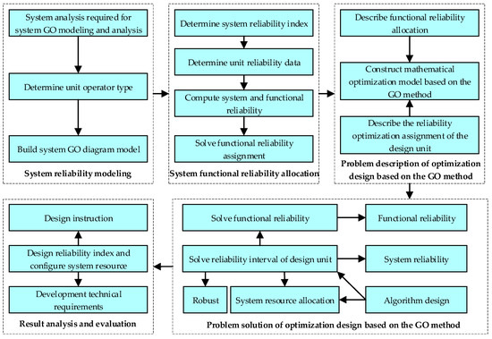
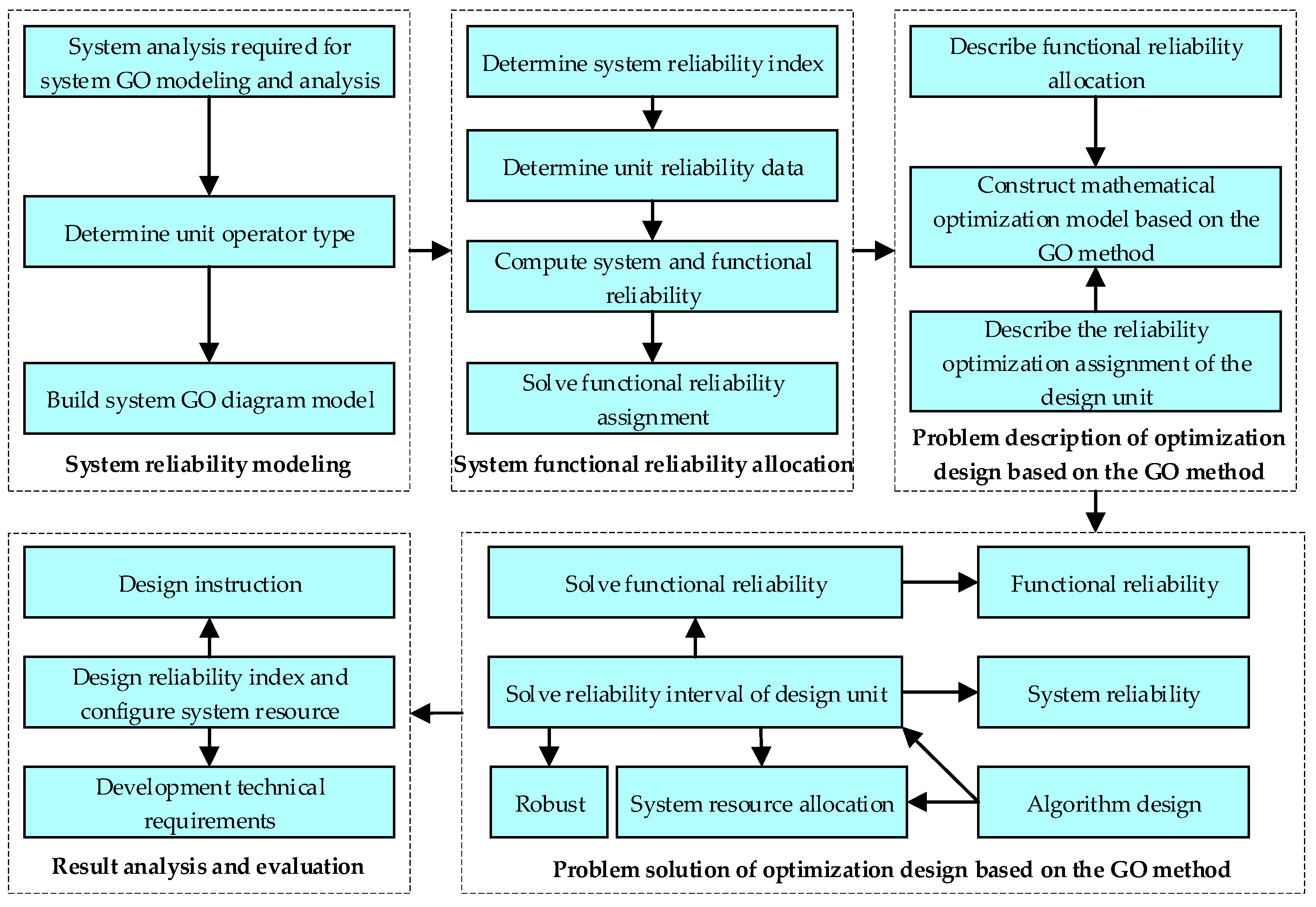
Given the main challenges currently faced by the reliability optimization design of the engine system, the GO method, which can better reflect the actual structure of the product, is employed in this paper to model and analyze the reliability of a V-type diesel engine. Its unit reliability interval optimization design is performed under minimum resource usage, large reliability, and robust distribution results. In addition, a three-level optimization design model of system–function–unit considering functional differences is constructed following the characteristics of the diesel engine. The reliability optimization design of the diesel system is divided into two main steps: (1) GO diagram modeling and function assignment and (2) the design of the unit reliability interval. The process of diesel engine reliability optimization design based on the GO method is developed from three aspects: the establishment of a unit reliability optimization model based on the GO method, the solution of the optimization model, and the analysis and evaluation of optimization results, as illustrated in Figure 1.
Figure 1.
Process of diesel reliability optimization design based on the GO method.
2. Diesel Engine Reliability Modeling and Distribution Based on the GO Method
2.1. Diesel Engine System Analysis
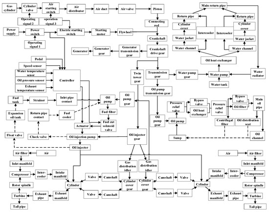
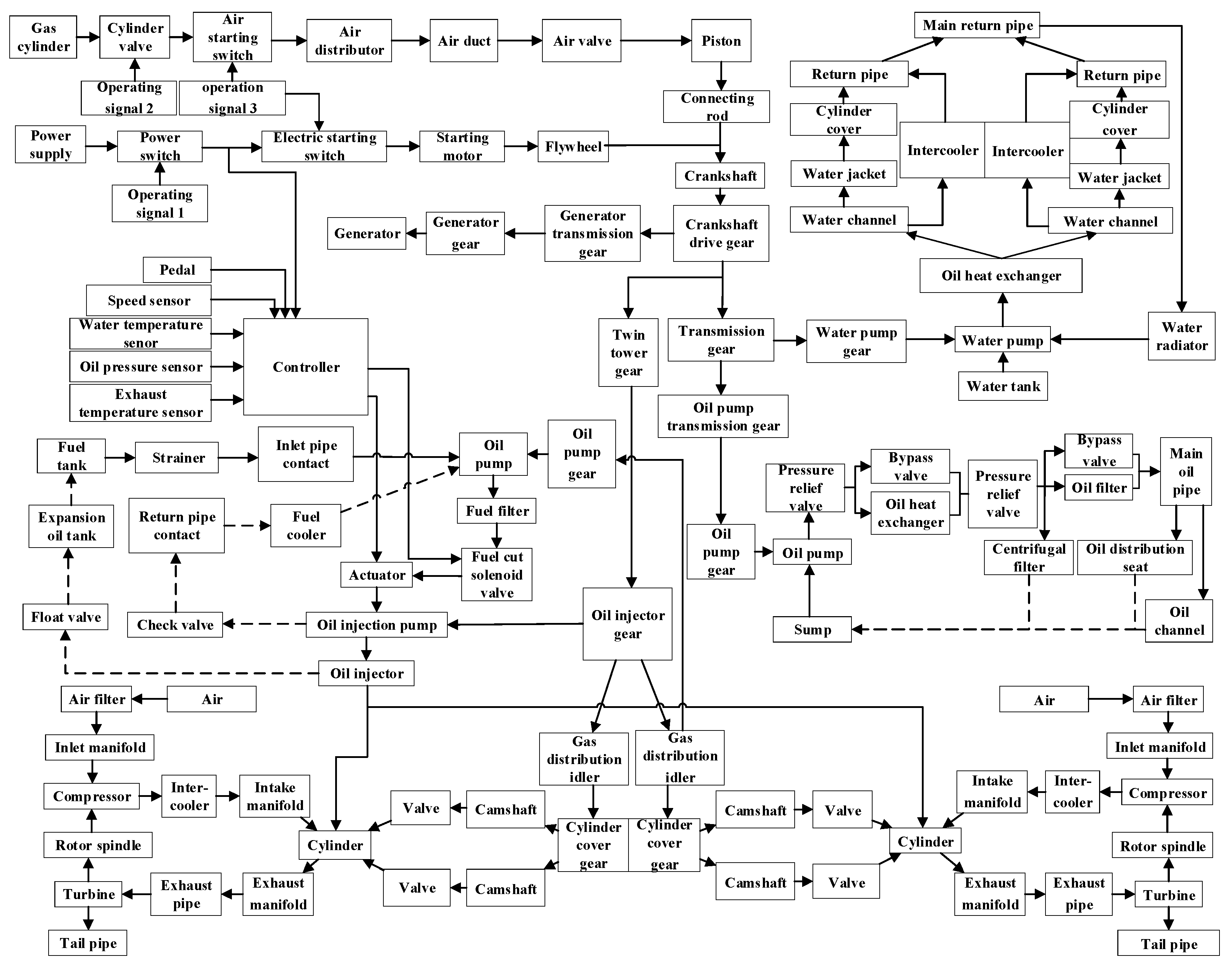
The diesel engine system is composed of a crank connecting the rod mechanism, valve mechanism, transmission mechanism, fuel supply system, inlet, exhaust, and turbocharge system, lubrication system, cooling system, starting system, and electronic control system. The electronic control system provides the electronic control signal for the starting system, which feeds back the state of the engine in real-time and adjusts the amount of fuel through various sensors. The starting system adopts two starting modes—dominated by high-pressure air starting and supplemented by electric starting—to satisfy the reliable and fast starting of diesel engines in various environments. The crank connecting rod mechanism converts the reciprocating motion of the piston into the rotating motion of the crankshaft through rod connection, driving the transmission mechanism to operate. Regarding the transmission mechanism, the valve mechanism, cooling system, lubrication system, fuel supply system, and generator are driven through the gearing transmission of the crankshaft and each transmission gear. The valve mechanism directly achieves timely opening and closing of the valve through the rotating motion of the double-top camshaft to ensure fresh air into the cylinder and exhaust gas out of the cylinder. The fuel in the fuel tank is filtered by a strainer and pressed into the fuel filter by the fuel pump. The filtered fuel enters the injection pump. The injection pump produces high-pressure fuel, which is injected into the cylinder by an injection pump. The return fuel of the injection pump passes through the fuel radiator and returns to the fuel pump. The return fuel of the injector flows into the expansion tank through the float valve. The cooling system is a single-pump and single-cycle cooling system. The water pump pumps the water out of the tank and passes it through a fuel heat exchanger to cool fuel. Then, the water enters a parallel water channel and intercooler to cool high-temperature air. Finally, the water enters the radiator to be cooled through the return pipe and then flows back to the water pump, completing the whole closed cycle. The engine oil in the sump is pressed into the oil heat exchanger through an oil pump. The cooled oil is divided into two ways: (1) entering into the centrifugal filter and the clean oil returning to the sump after filtering and (2) entering into the main oil channel through the oil filter and then going through various pipelines to lubricate each lubricating point and cooling point of the diesel engine, finally returning back to the sump. The air filtered by the air filter is pressed into the inlet manifold by the compressor, and the air is cleaned and transported to the cylinder under the action of the valve mechanism, contributing to the formation of a combustible mixture with the fuel atomized by an injector and burn. Under the action of the valve mechanism, the high-temperature exhaust gas with a certain pressure and flow rate is discharged from the cylinder into the exhaust manifold while influencing the turbine through the turbine shell in a certain direction to make the turbine rotate at a high speed. The finished exhaust gas is finally emitted into the atmosphere. The operating principle is illuminated in Figure 2.
Figure 2.
Operating principle of the diesel engine system.
2.1.1. Input–Output Boundary Condition Analysis of the Diesel Engine System
The system analysis suggests that the input of the diesel engine system consists of power supply, high-pressure gas cylinder, water tank, air, operation signal, and various sensor signals, while the output of the system involves the normal operation of the diesel engine, cooling system and lubrication system, and the normal discharge of reaction exhaust gas.
2.1.2. System Feature Analysis
As revealed in the system analysis and engineering practice, the diesel engine system has standby correlation structures and multi-closed-loop feedback structures, whose characteristics are detailed as follows.
(1) Standby correlation structure
The starting system of the diesel engine is a redundant system composed of high-pressure air starting and electric starting. The oil heat exchanger, as well as its by-pass valve and oil filter, also constitute the standby structure of system.
(2) Multi-closed-loop feedback structure
The system analysis, cooling system, lubrication system, fuel supply system, and inlet, exhaust, and turbocharge system all have multi-input and multi-closed-loop feedback structures.
2.2. Establishment of the GO Diagram Model for Diesel Engine System
2.2.1. Selection of Diesel Engine System Unit Operator
The system operators of the diesel engine are listed in Table 1. The operator types are regulated as Type 1 for the two-state unit, Type 5 for the signal generator, Type 6 for the signal-enabled element, Type 13 for multiple input and multiple output unit, Type 24B for multiple closed-loop feedback structures, Type 10 for the AND gate, Type 18A and Type 20 for operator standby correlation structure, and Type 23 signal integrated gate.
Table 1.
Diesel engine system unit operators, reliability data and parameters.
2.2.2. The GO Diagram Model of the Diesel Engine System
The GO diagram model of the diesel engine system is established on the basis of the system analysis and GO diagram model building method. The diesel engine system involving multiple closed-loop feedback structures is complex and has many components. Thus, this paper adopts a two-level GO diagram for modeling [15]. First, the first-level GO diagram model is constructed, followed by the second-level GO diagram model, namely the GO diagram model of the diesel engine system.
(1) The first-level GO diagram model of the diesel engine system
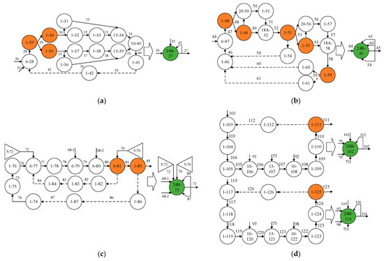
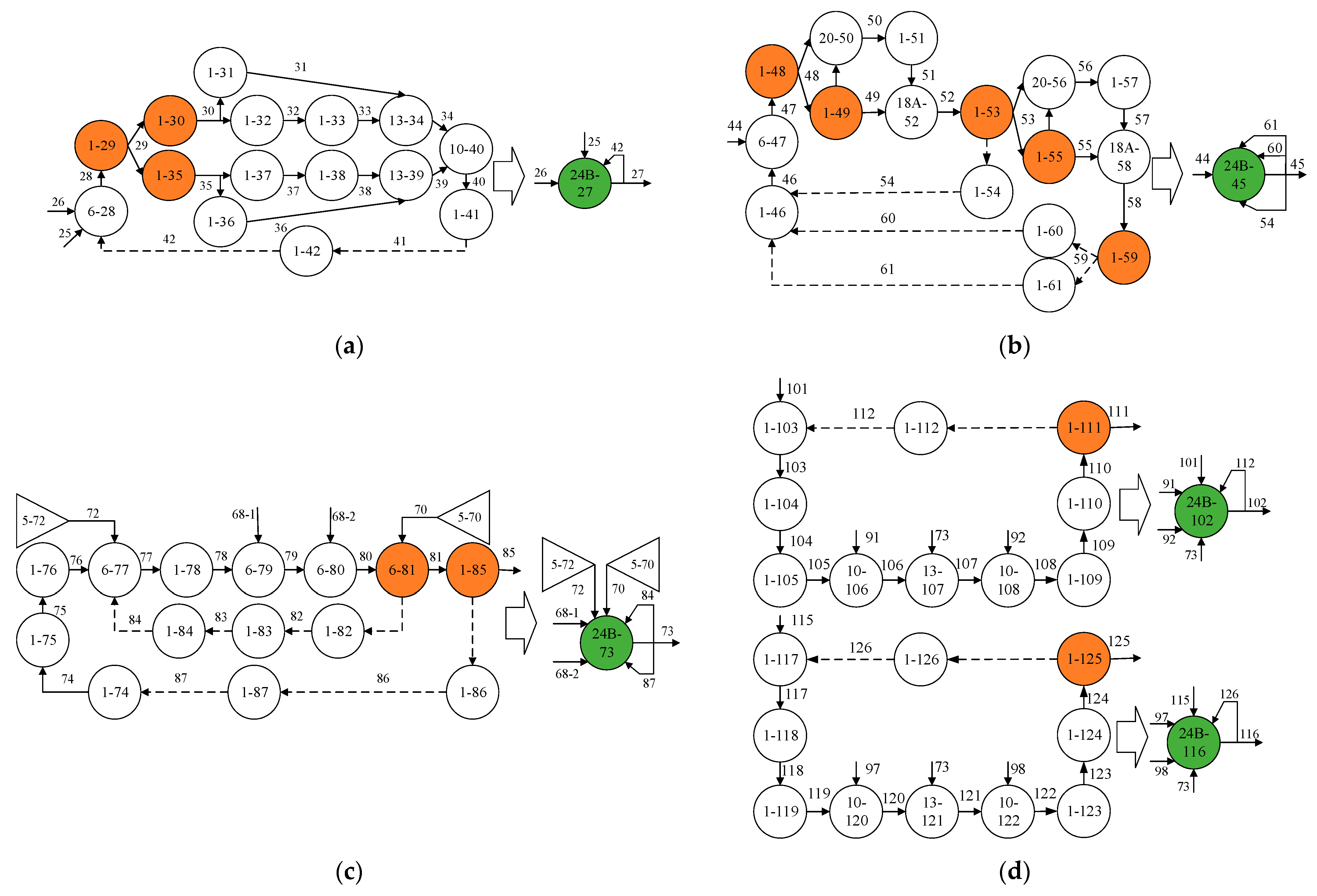
The four sub-systems of the diesel engine, including the cooling system, lubrication system, fuel supply system, and inlet, exhaust, and turbocharge system, contain closed-loop feedback structures, as suggested by analyzing the structure, operating principle, and function of the diesel engine system. The first-level GO diagram model is built for the closed-loop feedback structures of the four sub-systems, as exhibited in Figure 3.
Figure 3.
The first-level GO diagram model of the diesel engine system. (a) First-level GO diagram model of the cooling system; (b) First-level GO diagram model of the lubrication system; (c) First-level GO diagram model of the fuel supply system; and (d) First-level GO diagram model of the inlet, exhaust, and turbocharge system.
(2) The GO model of the diesel engine system
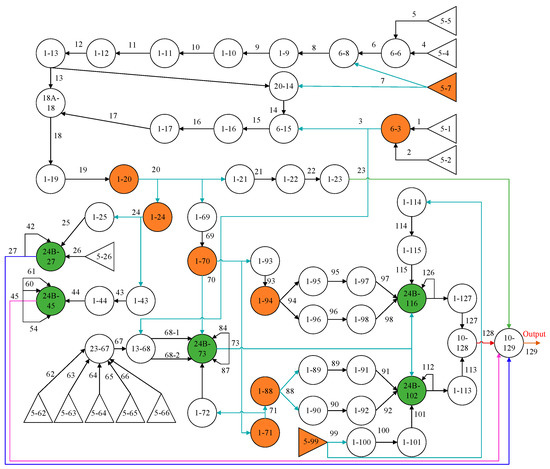
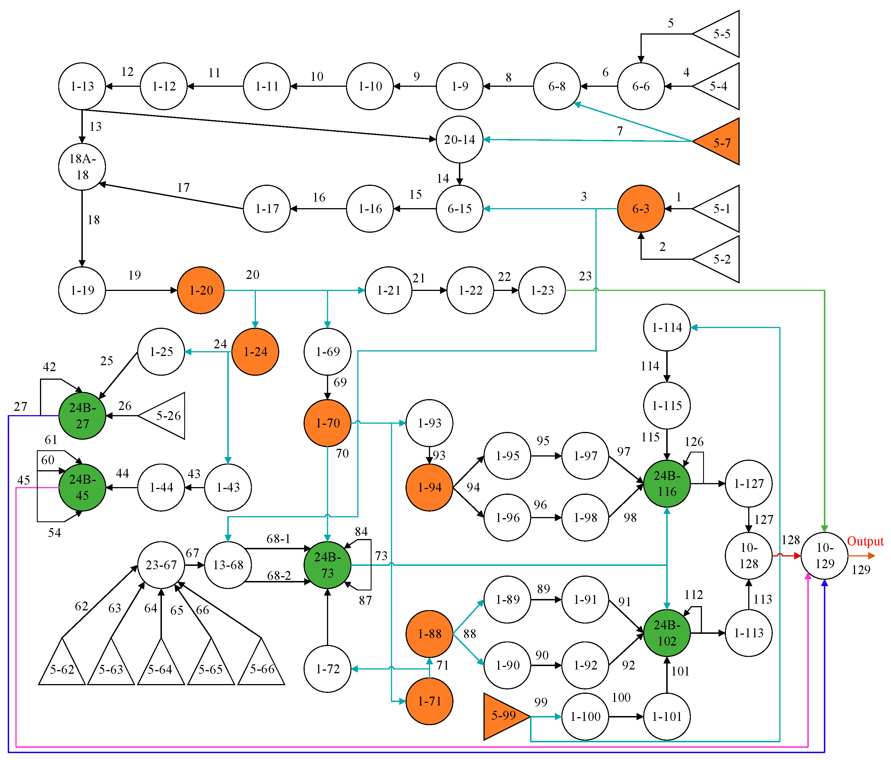
With the system analysis and Table 1, the first-level GO diagram model is integrated into the second-level GO diagram model to form the GO diagram of the diesel engine system, as illuminated in Figure 4. The first digit of the operator represents its number, and the second digit represents its type. The digit on the signal flow indicates its number. Signal flows 23, 27, 45, 128, and 129 are the power, cooling, lubrication, and exhaust functions of the diesel engine, and the output signal flows of the system, respectively.
Figure 4.
GO diagram model of the diesel engine system.
2.3. The Functional Reliability Distribution of the Diesel Engine
The reliability data of units in Table 1 reflect that the system reliability of the diesel engine is 0.9188, which is obtained by using the accurate algorithm [20] to perform GO calculation. The functional reliability is listed in Table 2.
Table 2.
Functional reliability of the diesel engine system.
The reliability of the newly designed diesel engine system is 0.99. The functional unreliability of the diesel engine system is allocated according to Formula (1), with the distribution results presented in Table 3.
where and denote the functional and system unreliability of new products, respectively; and indicate the functional and system unreliability of old products, respectively.
Table 3.
Functional reliability distribution of the diesel engine.
3. Problem Description and Model Building and Solution
3.1. Problem Description
In the engineering field, the higher the reliability, the greater the cost. The traditional multi-objective optimization problem is to find an optimal point that maximizes system reliability and minimizes total cost. Generally, the goals of maximum reliability and minimum cost are contradictory. Thus, there are many Pareto optimal points in traditional optimization problems. In addition, traditional methods neglect the robustness of allocation for the selection of Pareto optimal points. Therefore, our study allocates the unit reliability interval, with the minimum resource usage, large reliability, and robust distribution as optimization objectives, while considering the system characteristics, such as multi-function, multi-closed-loop feedback, and system structure. Therefore, the system reliability optimization design can be performed at the system-unit level (considering the functional difference) to obtain the unit reliability optimization design interval under the constraint of the system-function level to obtain the functional reliability index.
3.2. Establish the Optimization Model
3.2.1. Objective Function
Considering both optimal performance (maximum system reliability and minimum total cost) and robustness (maximum unit reliability interval), this study aims to find a hyper-rectangle whose volume is as large as possible, reliability as high as possible, and total cost as little as possible.
(1) Reliability hyper-rectangle volume function
The m unit reliability interval of the diesel engine constitutes an m-dimensional hyper-rectangle whose volume function is taken as a logarithmic volume function in this study.
(2) Reliability function
The reliability function can be obtained by the GO method.
(3) Cost function
Common reliability–cost function models comprise the logarithmic model, power function model, three-parameter cost function model, and four-parameter cost function model [21]. The reliability values of three-parameter and four-parameter cost function models cannot reach the upper limit. Thus, the cost-reliability model constructed in this paper is expressed in Equation (3) based on the general principles of cost–reliability function model construction.
where denotes the cost factor evaluated according to engineering practice (such as material, manufacturing, and processing).
3.2.2. Constraints
The constraints of the optimization model in this paper are reliability constraints. The system’s reliability should satisfy the requirements of design objectives. The function reliability should meet the requirements of allocation objectives. The unit reliability should meet the reliability range of engineering practice.
3.2.3. Optimization Model
A three-objective optimization model is constructed with the maximization of reliability hyper-rectangle volume , maximization of system reliability , and minimization of cost as optimization objectives, expressed in Equations (4)–(7).
where indicates the hyper-rectangle composed of m reliability intervals; represents the volume of hyper-rectangle; , , , , and signify the global minimum of power generation reliability function , cooling reliability function , lubrication reliability function , exhaust reliability function , and system reliability function in hyper-rectangle , respectively; refers to the global maximum of the cost function in hyper-rectangle ; and indicate the upper and lower limits of unit reliability, respectively; and and denote the upper and lower boundaries of hyper-rectangle, respectively.
3.3. Algorithm Design
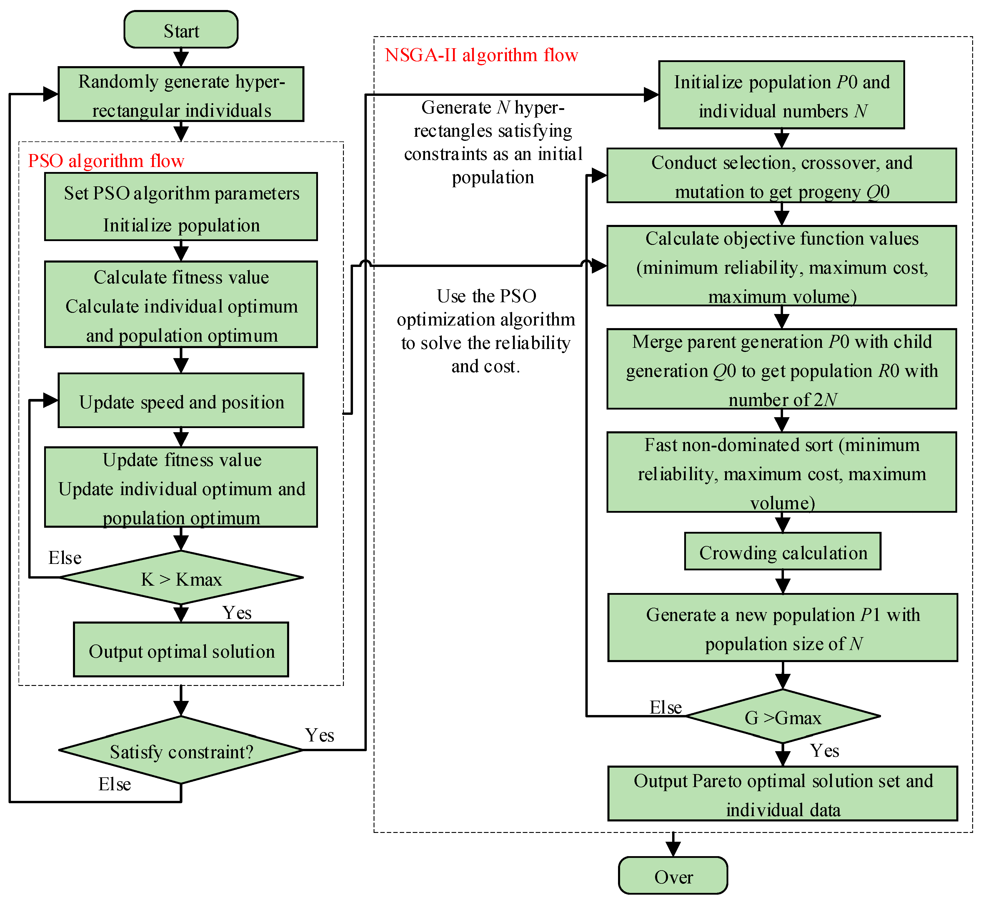
The diesel engine optimization design model constructed in this paper is a three-objective optimization model. Concerning the solution of such a model, the weighted sum method is generally applied to convert the multi-objective optimization into single-objective optimization. This method is simple to realize. Nevertheless, it is required to determine the weight subjectively, and only one feasible solution can be given for each run. The NSGA-II algorithm, which is a multi-objective optimization algorithm, is proposed on the basis of a genetic algorithm, adding a fast non-dominated sorting strategy and crowding comparison operator [22] in the selection operation. A Pareto solution set can be obtained for each run, and users can choose different design schemes following actual demands. The particle swarm optimization algorithm has acquired increasing attention owing to its advantages in global search ability, convergence speed, and accuracy, and it is an intelligent algorithm with great application potential [23]. Particle swarm optimization algorithm can be adopted to accurately calculate the global optimal value of the reliability function and cost function on . With the purpose of solving the three-objective reliability optimization design model, the PSO algorithm is embedded into the NSGA-II algorithm, and a hybrid NSGA-II-PSO algorithm based on the GO method in this paper is proposed. The specific steps are described as follows.
- Step 1:
- Initialize and generate initial population . Initialize the variables and parameters of the algorithm. Determine the population size N and the maximum iterations . Generate by the PSO algorithm with the reliability of the diesel engine system and function as constraints.
- Step 1.1:
- Generate hyper-rectangle individuals. Within the range of m unit reliability, randomly generate m intervals to form an m-dimensional hyper-rectangle D.
- Step 1.2:
- Initialize variables and parameters of the PSO algorithm, determine the population size M, and set the maximum iterations .
- Step 1.3:
- Run the PSO algorithm to output the optimal reliability value of the diesel engine system and function.
- Step 1.4:
- Determine whether all constraints are satisfied. If not, generate new individuals again until the generated N individuals satisfy the conditions and use as initial population .
- Step 2:
- Select, cross, and mutate individuals in population to obtain a new population with a population size of N.
- Step 3:
- Combine population and to form a new population with a population size of 2N. Calculate the value of objective functions. In each hyper-rectangle satisfying the constraint conditions, solve the minimum reliability and maximum cost of the diesel engine system using the PSO optimization algorithm, and calculate the volume of the hyper-rectangle.
- Step 4:
- Perform fast non-dominated sorting on and calculate its crowding distance in accordance with the maximum system reliability, minimum cost, and maximum hyper-rectangle volume.
- Step 5:
- After sorting population according to Pareto rank and crowding distance, select N individuals as the next generation population by elitism strategy and competition strategy.
- Step 6:
- Determine whether G is equal to the maximum evolution generation. If not, return to Step 2.
- Step 7:
- Output Pareto optimal solution set, save the individual data of the optimal solution set, and finish the algorithm operation.
The algorithm flow is presented in Figure 5.
Figure 5.
Flowchart of NSGA-II-PSO algorithm.
4. Results and Analysis
4.1. Experimental Setting
Table 4 describes the parameter settings of the NSGA-II-PSO algorithm in this paper.
Table 4.
Parameter settings of NSGA-II-PSO algorithm.
4.2. Optimization Result
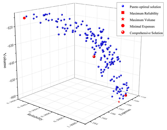
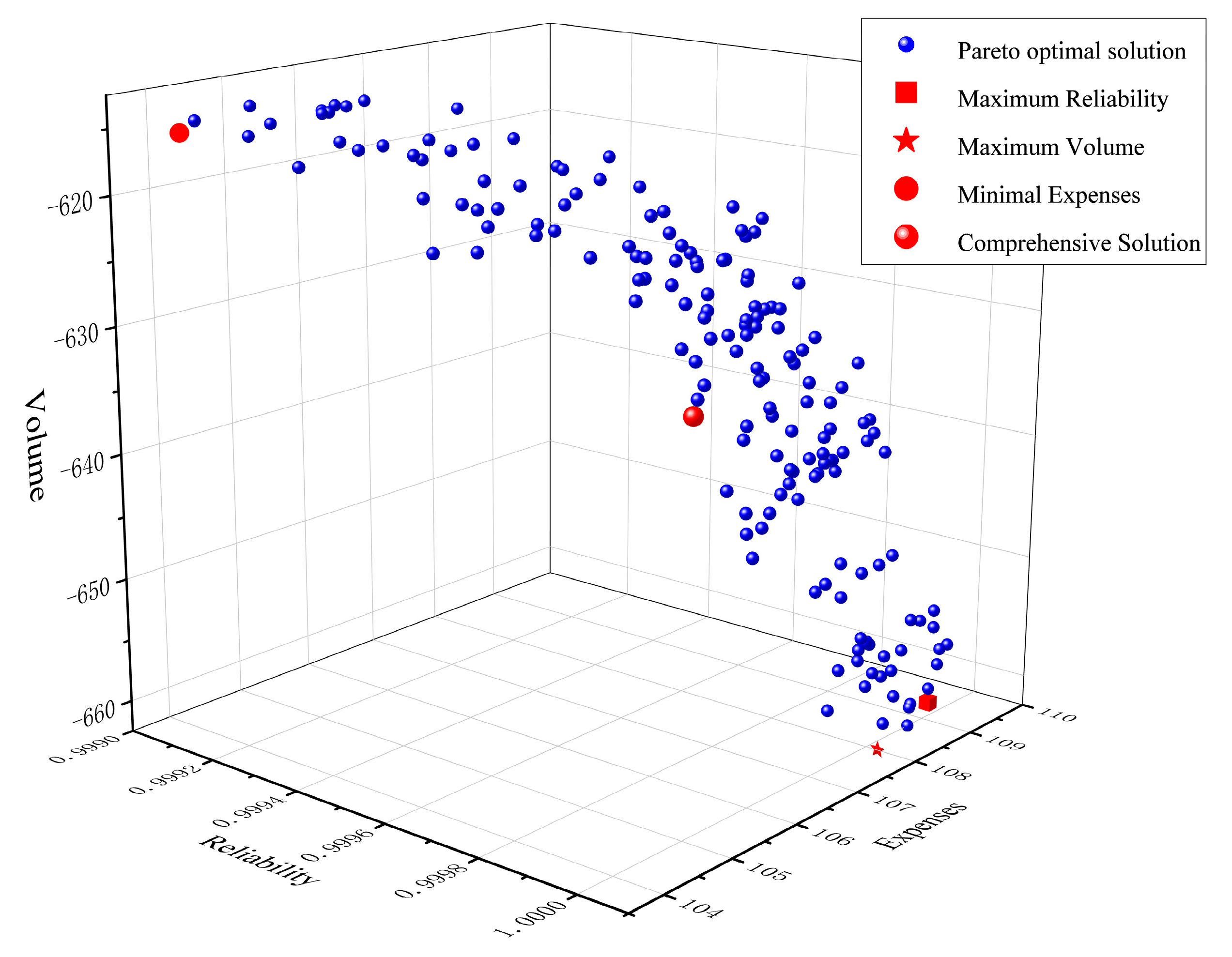
The NSGA-II-PSO algorithm obtains 170 Pareto optimal solutions of diesel reliability optimization design models (Figure 6). In other words, there are 170 design schemes available for selection. Partial Pareto optimal solution sets are listed in Table 5. Among them, No. 1 is the solution with the maximum reliability hyper-rectangle volume; No. 2 is the solution with the maximum reliability; No. 3 is the solution with the minimum cost; and No. 4 is the balance solution of volume, reliability, and cost, whose corresponding unit reliability intervals are provided in Table 6.
Figure 6.
Pareto solution of the diesel engine reliability optimization design.
Table 5.
Partial Pareto solution set of the diesel engine optimization design.
Table 6.
Reliability of unit corresponding to Pareto solution set of the diesel engine optimization.
5. Conclusions
With a V-type diesel engine as the research object, a reliability optimization design method for diesel engines based on the GO method was proposed in this paper. It has the objectives of low cost, high reliability, and high robustness.
- The diesel engine is a typical complex system with time sequence and multiple closed-loop feedback. Through the analysis of the diesel engine system, the GO diagram model, which is closely fitted with the composition, structure, and operating principle of the diesel engine, is established. Meanwhile, the reliability of the diesel engine system is evaluated by using the GO method.
- Given the limitations of existing reliability optimization design methods for engineering systems, a system reliability optimization design method based on the GO method is designed. This method considers the difference between diesel engine system functions and the allocation margin, realizes the multi-objective trade-off of maximum reliability, minimum cost, and best robustness, and obtains the design range of unit reliability, more consistent with the actual engineering needs.
- The algorithm proposed in this paper can obtain various design schemes. It considerably satisfies the subjective preferences of engineers and technicians while providing certain references for the reliability optimization design of other similar equipment.
Author Contributions
Conceptualization, Y.C., H.M. and X.Y.; methodology, Y.C., H.M. and X.Y.; software, Y.C. and S.W.; validation, Y.C., H.M. and S.W.; formal analysis, Y.C. and S.W.; investigation, H.M. and X.Y.; resources, H.M. and X.Y.; data curation, Y.C. and S.W.; writing—original draft preparation, Y.C. and S.W.; writing—review and editing, Y.C. and S.W.; project administration, H.M. and X.Y. All authors have read and agreed to the published version of the manuscript.
Funding
This research was funded by the Special Support Project of SASTIND and Technology Foundation Project of SASTIND (JSZL2019XXXB001).
Institutional Review Board Statement
Not applicable.
Informed Consent Statement
Not applicable.
Data Availability Statement
All datasets are publicly available.
Conflicts of Interest
The authors declare no conflict of interest.
References
- Bajerlein, M.; Bor, M.; Karpiuk, W.; Smolec, R.; Spadlo, M. Strength analysis of critical components of high-pressure fuel pump with hypocycloid drive. Bull. Pol. Acad. Sci.-Tech. Sci. 2020, 68, 1341–1350. [Google Scholar]
- Zhang, M.; Liu, S.; Hou, X.; Dong, H.; Cui, C.; Li, Y. Reliability Modeling and Analysis of a Diesel Engine Design Phase Based on 4F Integration Technology. Appl. Sci. 2022, 12, 6513. [Google Scholar] [CrossRef] [Scilit]
- Wang, D.F.; Yang, H.X. Reliability Design Analysis of Engine. Intern. Combust. Engine Accessories 2021, 333, 37–38. [Google Scholar]
- Zhao, S.Z.; Ma, J.J.; Zhao, L.H.; Zheng, S.L.; Chen, T.; Yu, J.W. Evaluation of Fuel Cell Engine Reliability Based on Optimal Parameters. Agric. Equip. Veh. Eng. 2018, 56, 20–24. [Google Scholar]
- Xie, X.P.; Ren, C.H.; Zhang, J.; Shen, J. Reliability Distribution Modeling and Reliability Research on X Engine. Ship Electron. Eng. 2016, 36, 114–118. [Google Scholar]
- Yin, F.; Wen, Y.X.; Chen, D.; Mou, Y.Y.; Yue, Y.L. Function Reliability Analysis of Underwater Control System based on RBD Control. China New Technol. New Prod. 2022, 472, 24–27. [Google Scholar]
- Liu, S.; Wang, H.Y.; Cao, F.Y.; Liu, Y. Study on frequency converter fault and reliability of wind turbine based on fault tree analysis. Electr. Appl. 2022, 41, 61–68. [Google Scholar]
- Chen, F.J.; Mi, J.; Zhang, S.L.; Chen, J.H.; Gui, P.; Ge, H.X. An FMECA method of hydraulic mechanical integrated transmission. J. Beijing Univ. Inf. Sci. Technol. (Nat. Sci. Ed.) 2022, 37, 52–56. [Google Scholar]
- Shen, Z.; Huang, X. Principle and Application of GO Method: A System Reliability Analysis Method; Tsinghua University Press: Beijing, China, 2004. [Google Scholar]
- Yi, X.J. A new system reliability analysis method: The current development of GO methodology in China. In Proceedings of the International Conference on Quality, Reliability, Risk, Maintenance and Safety Engineering, Beijing, China, 21 July 2015. [Google Scholar]
- Yi, X.; Dong, H.; Jiang, J. Reliability analysis of hydraulic transmission oil supply system of power-shift steering transmission based on GO methodology. J. Donghua Univ. 2014, 31, 4. [Google Scholar]
- Yi, X.; Dong, H.; Jian, S. Reliability analysis of hydraulic transmission oil supply system considering maintenance correlation of parallel structure based on GO methodology. In Proceedings of the International Conference on Reliability, Guangzhou, China, 13 May 2014. [Google Scholar]
- Yi, X.J.; Shi, J.; Dong, H.P. Reliability analysis of repairable system with multiple fault modes based on Goal-Oriented Methodology. ASCE-ASME J. Risk Uncertain. Eng. Syst. Part B Mech. Eng. 2016, 2, 9. [Google Scholar] [CrossRef] [Scilit]
- Yi, X.J.; Dhillon, B.S.; Shi, J. Reliability Analysis Method on Repairable System with Standby Structure Based on Goal Oriented Methodology. Qual. Reliab. Eng. Int. 2016, 32, 2505–2517. [Google Scholar] [CrossRef] [Scilit]
- Yi, X. Research on Key Technologies of Complex System Reliability Based on GO Method. Ph.D. Thesis, Beijing Institute of Technology, Beijing, China, 2016. [Google Scholar]
- Yi, X.J.; Shi, J.; Dong, H.P.; Lai, Y.H. Reliability analysis of repairable system with multiple-input and multi-function component based on go methodology. ASCE-ASME J. Risk Uncertain. Eng. Syst. Part B Mech. Eng. 2016, 3. [Google Scholar] [CrossRef]
- Yi, X.J.; Shi, J.; Mu, H.N. Reliability analysis on repairable system with dual input closed-loop feedback link considering shutdown correlation based on goal oriented methodology. J. Donghua Univ. 2016, 33, 314–318. [Google Scholar]
- Yi, X.J.; Jian, S.; Mu, H.N. Reliability analysis of hydraulic steering system with DICLFL considering shutdown correlation based on GO methodology. In Proceedings of the First International Conference on Reliability Systems Engineering, Beijing, China, 21 October 2015. [Google Scholar]
- Mu, H.; Cui, Y.; Hou, X.; Yi, X.; Ma, W.; Liu, W. Reliability Analysis of Repairable System with Multiple Closed-Loop Feedbacks Based on GO Method. J. Beijing Inst. Technol. 2022, 31, 431–440. [Google Scholar]
- Shen, Z.; Zheng, T. Exact algorithm for complex system reliability using the GO methodology. J. Tsinghua Univ. (Sci. Technol.) 2002, 569–572. [Google Scholar] [CrossRef]
- Wu, H.C.; Zhang, C. Optimization of System Reliability Allocation via Improved Cost Function. Mech. Sci. Technol. 2020, 39, 1323–1328. [Google Scholar]
- Deb, K.; Pratap, A.; Agarwal, S.; Meyarivan, T.A.M.T. A fast and elitist multi-objective genetic algorithm: NSGA-II. IEEE Trans. Evol. Comput. 2002, 6, 182–197. [Google Scholar] [CrossRef] [Scilit]
- Huang, S.R. Survey of particle swarm optimization algorithm. Comput. Eng. Des. 2009, 30, 1977–1980. [Google Scholar]


Disclaimer/Publisher’s Note: The statements, opinions and data contained in all publications are solely those of the individual author(s) and contributor(s) and not of MDPI and/or the editor(s). MDPI and/or the editor(s) disclaim responsibility for any injury to people or property resulting from any ideas, methods, instructions or products referred to in the content. |
© 2023 by the authors. Licensee MDPI, Basel, Switzerland. This article is an open access article distributed under the terms and conditions of the Creative Commons Attribution (CC BY) license (https://creativecommons.org/licenses/by/4.0/).