


Abstract
In this paper, we present an automatic procedure that enhances the solution accuracy of edge-based smoothed 2D solid finite elements (three-node triangular and four-node quadrilateral elements). To obtain an enhanced solution, an adaptive enrichment scheme that uses enriched 2D solid finite elements and can effectively improve solution accuracy by applying cover functions adaptively without mesh-refinement is adopted in this procedure. First, the error of the edge-based finite element solution is estimated using a devised error estimation method, and appropriate cover functions are assigned for each node. While the edge-based smoothed finite elements provide piecewise constant strain fields, the proposed enrichment scheme uses the enriched finite elements to obtain a higher order strain field within the finite elements. Through various numerical examples, we demonstrate the accuracy improvement and efficiency achieved.
1. Introduction
The finite element method (FEM) is one of the most successful numerical methods and has been widely used to solve mechanics problems in various engineering fields [1,2,3,4,5]. Despite its great success, the standard finite element method has some limitations: the analysis accuracy depends on the mesh used and the stress prediction accuracy is considerably poor when 3-node triangular (2D) and 4-node tetrahedral (3D) elements are used [5,6,7]. Many studies have been conducted to overcome these limitations of the standard FEM (ST-FEM), and several numerical methods, such as extended FEM (EX-FEM), enriched FEM (EN-FEM), and smoothed FEM (S-FEM), have been developed [7,8,9,10,11].
The S-FEM is a relatively recently proposed method among the several techniques mentioned above and has been successfully applied to various engineering problem [12,13,14,15,16,17,18,19,20,21,22,23,24]. In S-FEM, the strain smoothing technique originally developed for the Galerkin mesh-free method is applied to the FEM, and constant strain fields are constructed in newly defined smoothing domains [12,13]. Depending on how the smoothing domain is defined, node-based, cell-based, edge-based, and face-based smoothed FEM have been proposed. Each S-FEM has different characteristics and performance depending on the smoothing domain, and it is generally known that edge-based S-FEM (ES-FEM) is the most effective [19,20,21,22]. The solution accuracy of the ES-FEM is more accurate compared to the ST-FEM, especially when the same lower order element mesh is used, and unlike other methods such as EX-FEM and EN-FEM, no additional degrees of freedoms (DOFs) are required [6,8,11,25]. However, when high gradient occurs in the smoothing domain, the predictive ability of the ES-FEM with a lower order element mesh is not good enough to be used in engineering practice [25,26].
The enrichment scheme was developed as another method of improving finite element solution accuracy [5,9,11]. With the enrichment scheme, the solution space of the standard finite element can be expanded by introducing cover functions corresponding to enriched DOFs. The main advantage of the enriched FEM (EN-FEM) is that the solution improvement in the sense of the p-version of the ST-FEM is available without introducing additional nodes. In addition, adaptively applying the cover function to a local area where solution accuracy needs to be improved can enhance solution accuracy efficiently [5,11]. However, depending on the mesh used when applying the polynomial cover function, a linear dependence (LD) problem that leads to ill-conditioned global matrices can occur [27,28]. Many methods have been suggested to suppress the LD problem of enriched finite elements [3,29,30,31]. Among the suggested methods, the LD problem was resolved in a simple and effective way by adopting piecewise linear shape functions and suppressing enriched DOFs [32,33]. In addition, a procedure for automatically improving the analysis accuracy of the standard finite elements using enriched finite elements has been proposed [34,35]. In this procedure, the use of cover functions is determined automatically based on the analysis results of the standard finite elements. The mesh-refinement is not required, but the number of DOFs used increases.
In this paper, we propose an automatic procedure to effectively improve the solution accuracy of edge-based 2D solid finite elements (4-node quadrilateral and 3-node triangular) without mesh-refinement or introducing additional nodes. An error indicator that estimates the error of the finite element solution and cover function selection scheme based on the error indicator are adopted, and the enriched finite elements are employed to incorporate cover functions in the analysis results. The adaptive enrichment scheme can enhance the solution of edge-based finite elements and capture high gradients efficiently.
In the following sections, we firstly review the edge-based finite elements method (ES-FEM) and the enriched finite element method (EN-FEM). We then suggest an automatic procedure that provides solution improvement through adaptive enrichment including the error indicator and cover function selection scheme. Through several examples, the feasibility of improving the accuracy of edge-based 2D finite element solutions is demonstrated.
2. Enrichment Scheme for the Edge-Based Smoothed 2D Solid Finite Elements
In this section, we briefly review the edge-based smoothed three-node triangular and four-node quadrilateral elements (ES-QD4, ES-T3) and the enriched three-node triangular and four-node quadrilateral elements (EN-QD4, EN-T3), and suggest a strategy to obtain accurate solutions with an enrichment scheme.
It is not necessary to explicitly define the shape function to calculate the stiffness matrix of edge-based smoothed finite elements [6], but we present the formulation of edge-based smoothed finite elements (ES-FE) and enriched finite elements (EN-FE) with linear and piecewise linear shape functions [33]. These shape functions are adequate for ES-FE and EN-FE and also prevent the LD problem that can occur due to the enrichment scheme.
2.1. Edge-Based Smoothed 2D Finite Elements
The geometry of the ES-FE is given by
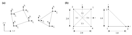
where is the position vector corresponding to node on the global Cartesian coordinate system shown in Figure 1a, is the number of nodes of element, and are the 2D linear interpolation functions corresponding to node defined in the natural coordinate system in Figure 1b. The four-node quadrilateral and three-node triangular elements have center points ( for the four-node element and for the three-node element) and are divided into four or three sub-triangles (cells), respectively, using its nodes and center points.
Figure 1.
Coordinate systems for a 2D solid finite element: (a) Global Cartesian coordinate system , and nodal local coordinate systems , and (b) natural coordinate system .
For the four-node quadrilateral element (), the piecewise linear shape functions defined in each triangular cell shown in Figure 1b are [32]
The linear shape functions for the three-node triangular element () are
where the linear shape functions are the same for all cells shown in Figure 1b.
The displacement of the ES-FE is interpolated by
in which is the displacement vector of node in the global Cartesian coordinate system.
Employing the standard isoparametric finite element procedure with Equations (1) to (4), the strain field within a cell c of an element e is obtained using
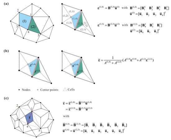
where , is the displacement-strain relation matrix on the cell c in the element e, is the nodal displacement vector of the element, and is the strain-displacement relation matrix corresponding to node i in cell c, as seen in Figure 2a. Since the geometry and displacement interpolations are based on the linear shape functions in Equations (2) and (3), the strain components in Equation (5) are constants in each cell.
Figure 2.
Strain smoothing domain for the edge-based smoothed element: (a) Finite element mesh. The red line corresponds to a target edge. (b) The elements are divided into cells. (c) Smoothing domains of the edge-based smoothed element and the smoothed strain in the smoothing domain.
For the ES-FEM, the smoothing domain is defined at each edge with its neighboring cells. Let us consider three-node triangular and four-node quadrilateral elements attached to the edge, colored in red (see, Figure 2). The edge-based smoothing domain is formed as the union of cells attached to the edge and belonging to different elements, and the smoothed strain corresponding to this smoothing domain is given by
in which and are the areas of cells attached to the target edge, and and are the strains of the neighboring cells. The strain field of the ES-FE is also constant in the smoothing domain, like the strain vector in Equation (5).
The edge-based smoothed strain within cell c of the target element e can be expressed in matrix and vector form as
where is the number of nodes belonging to elements including cells constituting the smoothing domain (see Figure 2c). The edge-based smoothed elements also have a constant strain field and pass all basic tests (patch, isotropy, and zero energy mode tests).
2.2. Enriched 2D Finite Elements
Here we review the formulation of the EN-FEM. The enrichment scheme can expand the solution space of the FEM without mesh refinement or additional nodes, and the solution accuracy can be improved effectively by considering the adequate cover function for a particular problem.
The geometry interpolation of the EN-FE is the same as the interpolation of the standard and smoothed finite elements and is given in Equation (1). The interpolation of displacement is given by multiplying the shape functions with cover functions defined over cover area as follows:
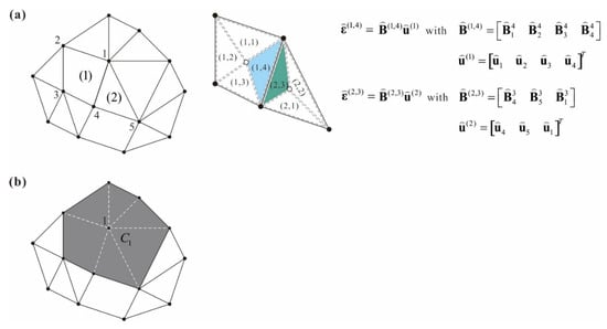
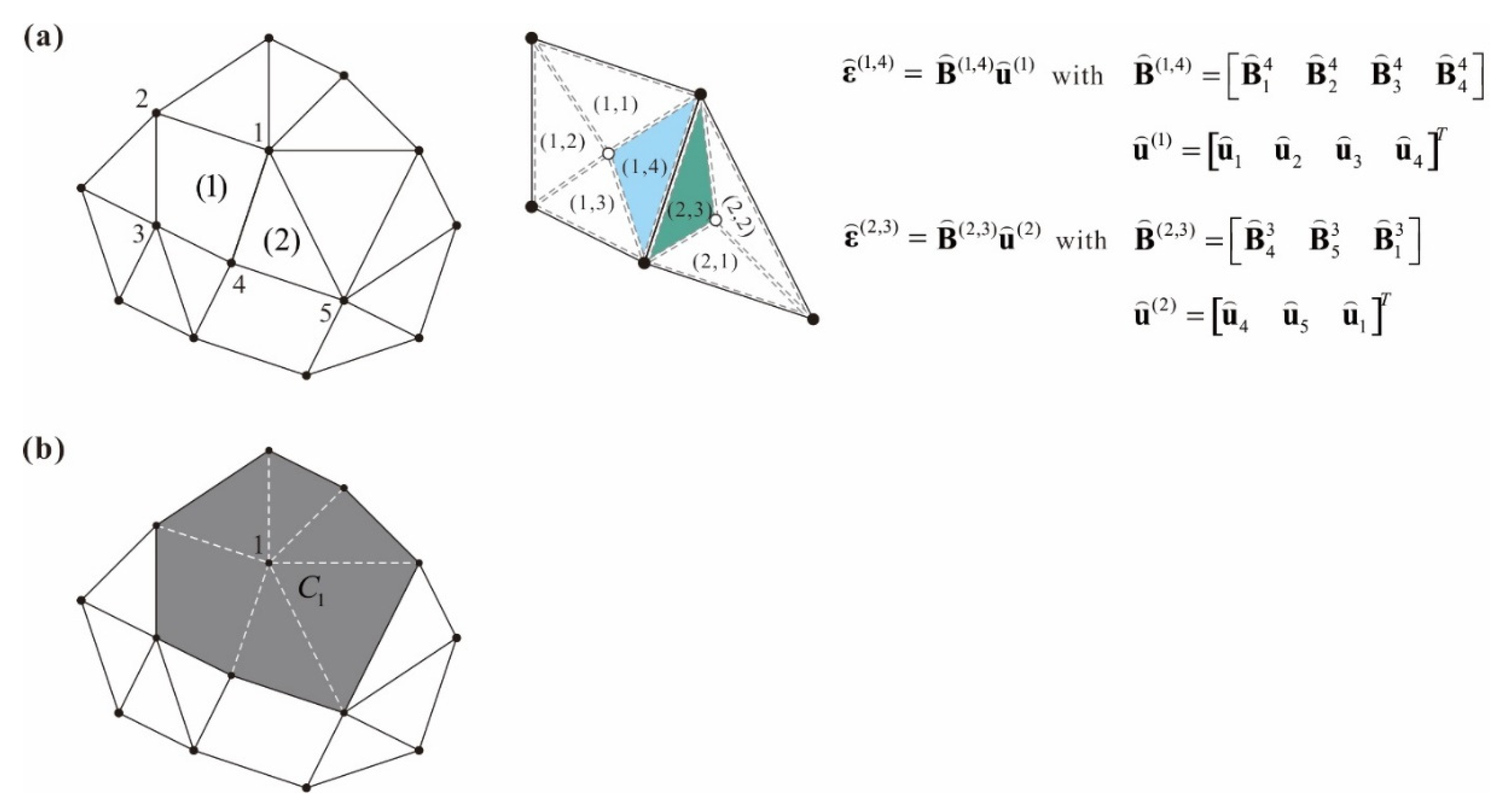
where and are cover functions for the displacements u and v, respectively. The cover area consists of elements attached to node i as shown in Figure 3.
Figure 3.
Description of the cover region: (a) Finite element mesh and linear/higher order strain part of element 1 and 2, (b) cover region corresponding to the node 1.
The polynomial cover functions are
with
where is the polynomial basis vector for node i, d is the degree of the polynomial bases, is the largest edge length of elements belonging to , and and are the degrees of freedom vectors corresponding to the bases of the polynomial cover functions for the displacements in the x- and y- directions, respectively.
Substituting cover functions in Equation (9) into Equation (8), the displacement interpolation is represented by
with
where and are the enriched DOFs vector and the corresponding interpolation matrix, respectively.
For the linear cover function used (), the following components of the interpolation matrix and the enriched DOFs vector are employed
When the quadratic cover function is used (), the components of the interpolation matrix and the enriched DOFs vector are
For the cubic cover function used (), the components of the interpolation matrix and the enriched DOFs vector become
Using the displacement–strain relation, the strain vector within cell c of the target element e is given by
with
in which is the enriched DOFs vector of the element e, and is the strain–displacement relation matrix corresponding to the enriched DOFs at node i in cell c of the target element e.
Note that the displacement of the ES-FE in Equation (12) is divided into two parts: Linear displacement and higheorder displacement . is the standard finite element interpolation and is the additional enriched higher order displacement interpolation.
This polynomial enrichment scheme improves the solution accuracy in the sense of the p-version of the ST-FEM without adding extra nodes, and the cover functions with different degrees of polynomial can be used for each node. Thus, by applying cover functions to a local area where solutions need to be improved can increase the finite element solution accuracy effectively without mesh refinement [32,33].
2.3. The Procedure for Improving Edge-Based Finite Element Solutions
There have been studies to improve the accuracy of the standard finite element solutions using the enrichment scheme. Kim and Lee presented an error indicator for each node to estimate the standard finite element solution error and proposed a scheme to apply polynomial cover functions to the appropriate node using the calculated error indicator [34]. This procedure can automatically improve the stress and displacement predictions and is effective in terms of computational cost since no mesh-refinement or extra nodes are required.
Here, we present an automatic procedure that effectively improves the solution accuracy of edge-based smoothed 2D solid finite elements (ES-FE) with enriched 2D solid finite elements (EN-FE). Similar to the previous proposed procedures, the improvement of the solution accuracy is composed of two steps. First, the ES-FE solution is calculated, and then the error for each node is estimated through the error indicator. Based on this error indicator, appropriate cover functions are selected for each node, and re-analysis is performed to obtain an improved analysis result.
The error indicator that estimates errors at each node is defined by
with
where is the stress at node i, is the largest stress jump at node i, is the number of nodes, and is the largest edge length of elements attached to node i [35]. The error indicator in Equation (19) does not include any artificial constants and any stress quantity of interest can be used for this error indicator. In this paper, the von Mises stress quantity is applied to all examples.
Based on the error indicator in Equation (19), the cover selection scheme determines the nodes to which the cover function is applied and the degree of the cover function. This scheme should include minimum parameters and present the optimal nodes and degrees of the cover function to improve the solution accuracy.
In the cover selection scheme, index (), which presents the arrangement of the nodal error indicator ( with ) in ascending order, is defined. Then, the ascending index () and normalized index () are given as follows:
and
By using the normalized index, a weighted average of the error indicator is given by
With the weighted average of the error indicator in Equation (23) and artificial parameters (), the cover selection is given as follows:
For nodes with larger errors, a higher degree of cover function is applied, and artificial parameters () are the only values that should be determined. Kim and Lee suggested using as default values and demonstrated several examples that showed very effective improvement of the solution accuracy. These values for parameters () are adopted for all examples in the following section.
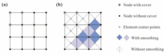
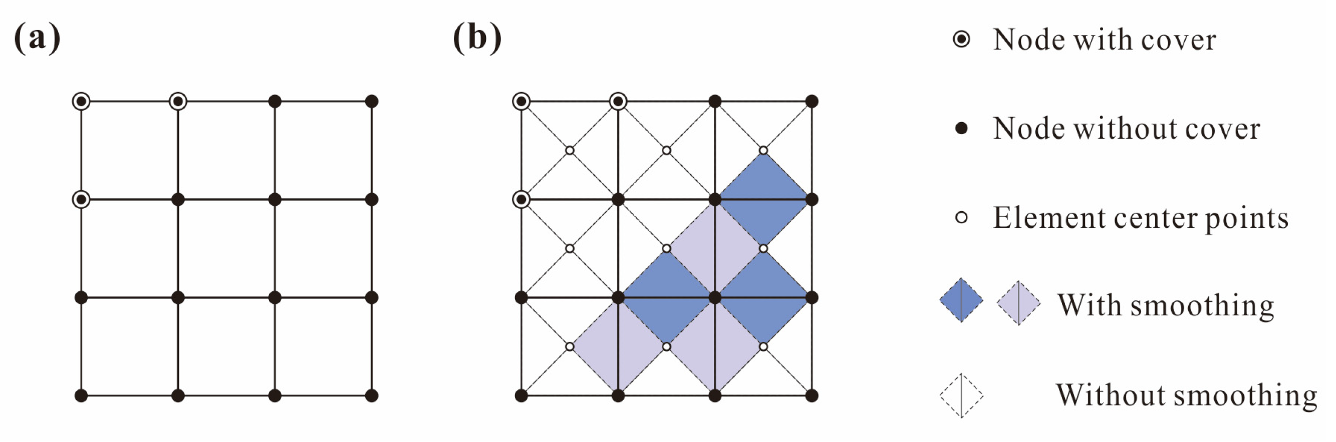
With the cover function selection scheme in Equation (24), the finite element model is updated to obtain a better solution and capture high gradients. The stiffness matrix of the updated FE model with smoothing and enrichment schemes can be calculated. As shown in Figure 4, smoothing and enrichment schemes are applied separately, so that they effectively provide low and high gradient solutions, respectively.
Figure 4.
Adaptive use of cover function for the edge-based smoothed finite element: (a) Finite element mesh with cover functions, (b) application of the edge-based smoothing scheme to elements without cover functions.
The presented procedure improves the solution accuracy of edge-based smoothed finite elements, which are known to have better performance than standard finite elements, while the automatic procedure proposed by Lee and Kim [35] improves the solution for standard finite elements. Iterative analysis is also possible by adopting a higher degree cover function or by applying a cover function to a node to which the cover function is not applied. Repeating this re-analysis requires parameter adjustment in Equation (24) at each iteration. The most accurate solution can be obtained when applying the highest order cover function to all nodes in a given finite element mesh. In this paper, we present a procedure that can effectively obtain an accurate solution through single re-analysis automatically without parameter adjustment.
We performed three basic tests (the isotropy, patch, and zero energy mode tests) with arbitrary cover function application to each case, as shown in Figure 4, and all cases passed these basic tests. With this cover selection scheme, the solution accuracy of the ES-FE can be improved effectively without mesh-refinement or introducing additional nodes and its performance is demonstrated through examples in the next section.
3. Numerical Examples
In this section, we demonstrate the feasibility of improving 2D ES-FE solutions with an adaptive enrichment scheme presented in the previous section. This procedure yields solutions with desired accuracy by applying appropriate cover functions for each node, and the higher-order displacement field can be obtained effectively. The Cook beam problem, Ad-hoc problem, Wheel problem, and L-shape structure problems are considered, and the finite element models are constructed using meshes of linear elements (four-node quadrilateral and three-node triangular elements) and quadratic elements (nine-node quadrilateral and six-node triangular elements).
Displacement, strain, von Mises stress, and energy norms were evaluated, and the relative errors of displacement () in the y-direction and von Mises stress () are given by
where the subscripts ‘h’ and ‘ref’ represent the finite element and the reference solutions, respectively. The energy norm E and its relative error are denoted by
The reference solutions are obtained using fine meshes of quadratic elements.
3.1. Cook’s Skew Beam Problem
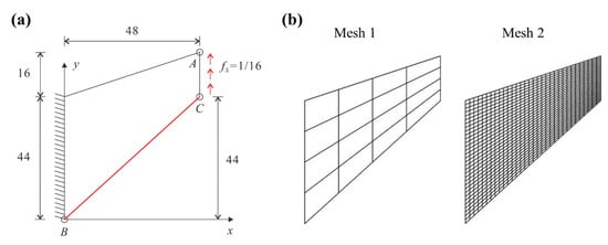
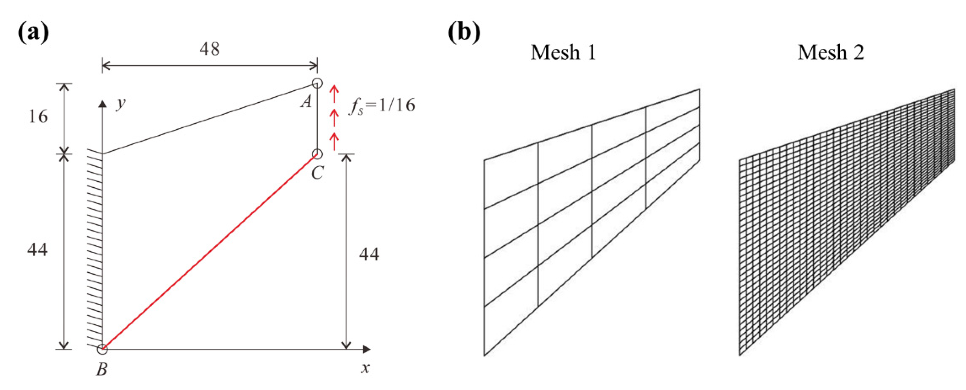
The first numerical example is the Cook beam problem shown in Figure 5 [4]. A distributed force is applied on the right edge, and the left edge is clamped. The plane stress condition is employed with Young’s modulus , Poisson’s ratio , and density . The two quadrilateral meshes are shown in Figure 5, where edge-based smoothed four-node quadrilateral element (ES-Q4) are used, and the proposed scheme is applied for each mesh to obtain solutions with improved accuracy.
Figure 5.
Cook’s skew beam problem: (a) Problem description. (b) Quadrilateral meshes (Mesh I and II) used.
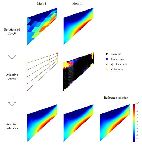
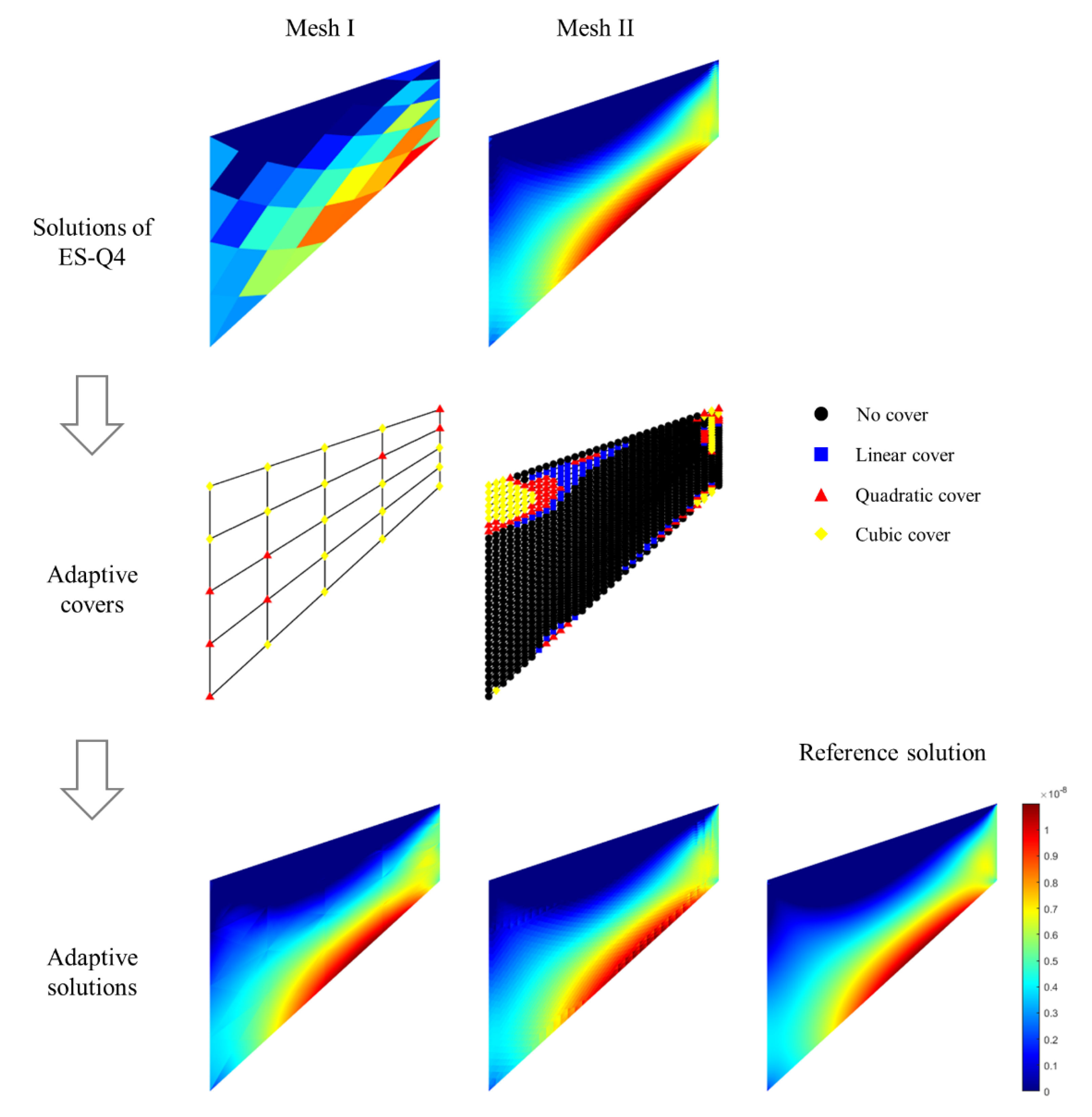
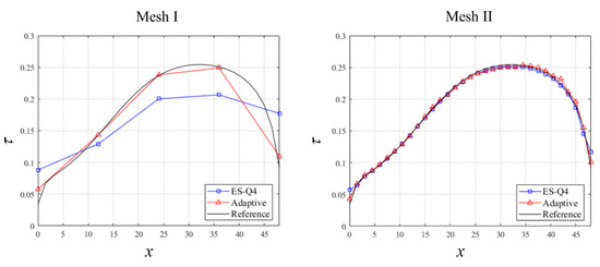
The relative errors of the vertical displacement in Equation (25) and the energy norm in Equation (27) are given in Table 1. Figure 6 provides the distributions of the strain component when the edge-based four-node quadrilateral elements (ES-Q4) and the proposed scheme are applied to the meshes shown in Figure 6. The distributions of the von Mises stress along line BC is given in Figure 7. The reference solution is calculated with a fine mesh of nine-node quadrilateral elements. The actual computational time for constructing the stiffness matrix and solving the linear system of equations are summarized in Table 2.
Table 1.
Relative errors (%) in the energy norm () and the vertical displacement () at the point A in the Cook’s skew beam problem.
Figure 6.
Strain () predictions obtained by the ES-Q4 and the proposed adaptive enrichment scheme for the Cook’s skew beam problem.
Figure 7.
von Mises stress () distributions along the line BC of the cook’s skew beam problem for the quadrilateral meshes shown in Figure 5.
Table 2.
Solution times (in seconds) for constructing the stiffness matrix and solving linear equations for the Cook’s skew beam problem.
It is shown that the calculated results of the strain energy norm, displacement, strain, and von Mises stress with the adaptive enrichment scheme are more accurate than those without cover functions. Furthermore, both the case of the adaptive cover in Mesh 1 and the case of using the linear element in Mesh 2 show sufficiently accurate results; however, the adaptive method consumes approximately three times less computational time.
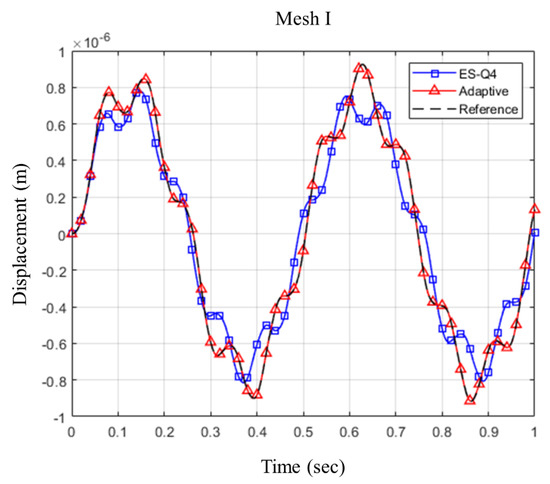
Transient response at point A is also calculated, and Newmark time integration method with is used. The initial condition and harmonic excitation at the right edge are given by
ES-Q4 and the adaptive enrichment scheme with Mesh 1 are used for dynamic analysis. The adaptive use of cover functions is the same with static analysis shown in Figure 6, and Figure 8 shows the transient response at Point A. The solution of the proposed scheme almost converges to the reference solution, and it is confirmed that the suggested scheme can improve not only the static but also dynamic solution accuracy effectively.
Figure 8.
Transient response (displacement in y-direction) at the point A in the Cook’s skew beam problem. The edge-based smoothed four-node element (EN-Q4), and adaptive enrichment scheme for the edge-based smoothed element (adaptive) are used with Mesh I.
3.2. Ad-Hoc Problem
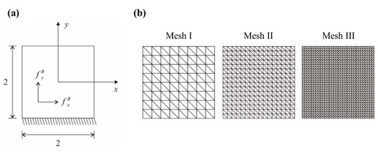
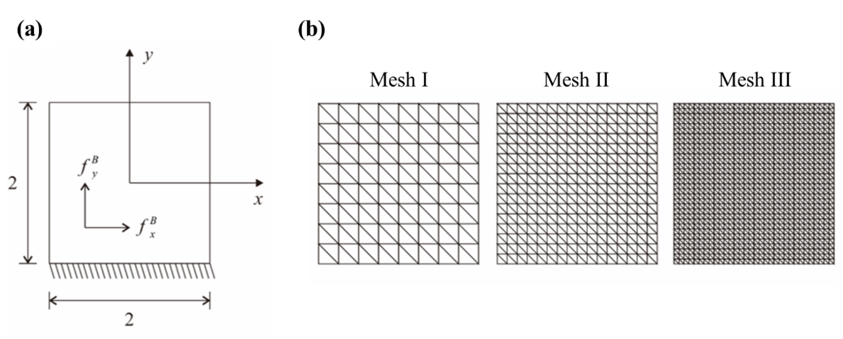
Here, the ad-hoc problem shown in Figure 9 is considered. For the given in-plane displacements
we can obtain the body forces satisfying the equilibrium equations
Figure 9.
Ad hoc problem: (a) Problem description. (b) Triangular meshes (Mesh I, II, and III) used.
The body forces are applied to the whole problem domain, and the fixed boundary condition is imposed on the bottom line ().
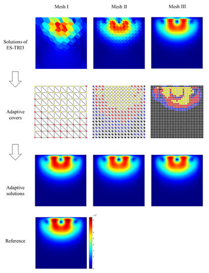
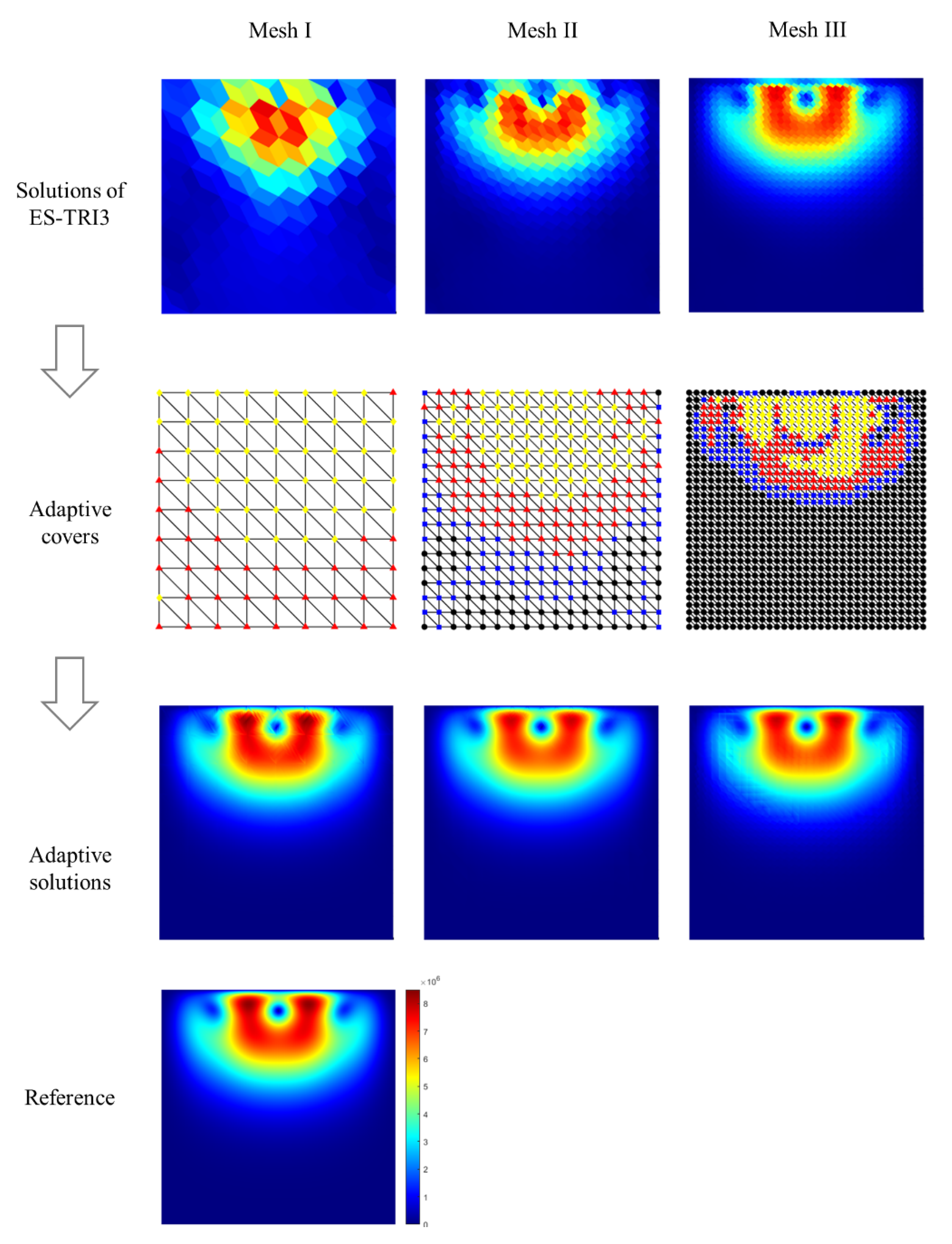
The plane stress condition is employed with and , and the solution is obtained using the three triangular meshes shown in Figure 9 with the edge-based three-node triangular elements (ES-T3) and the suggested adaptive enrichment scheme. The reference solutions are obtained using a fine mesh of the standard nine-node quadrilateral elements.
Figure 10 provides the von Mises stress distributions for the three triangular meshes shown in Figure 9 and the degrees of cover functions applied based on the adaptive enrichment scheme. The relative errors in the energy norm in Equation (27) and maximum von Mises stress that are averaged stress values at each node in Equation (26) are summarized in Table 3. The von Mises stress fields obtained by applying the adaptive enrichment scheme almost converge to the reference solution for all the meshes (Mesh I, II, and III) considered.
Figure 10.
von Mises () predictions obtained by the edge-based three-node triangular elements (ES-T3) and the proposed adaptive enrichment scheme for the ad hoc problem shown in Figure 9.
Table 3.
Relative errors (%) in the energy norm () and the maximum von Mises stress () in the ad hoc problem.
3.3. Wheel Problem
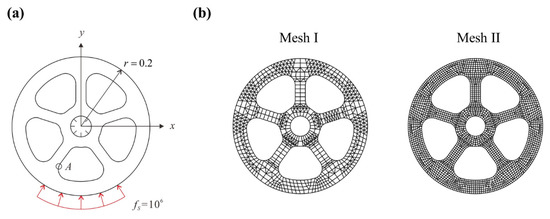
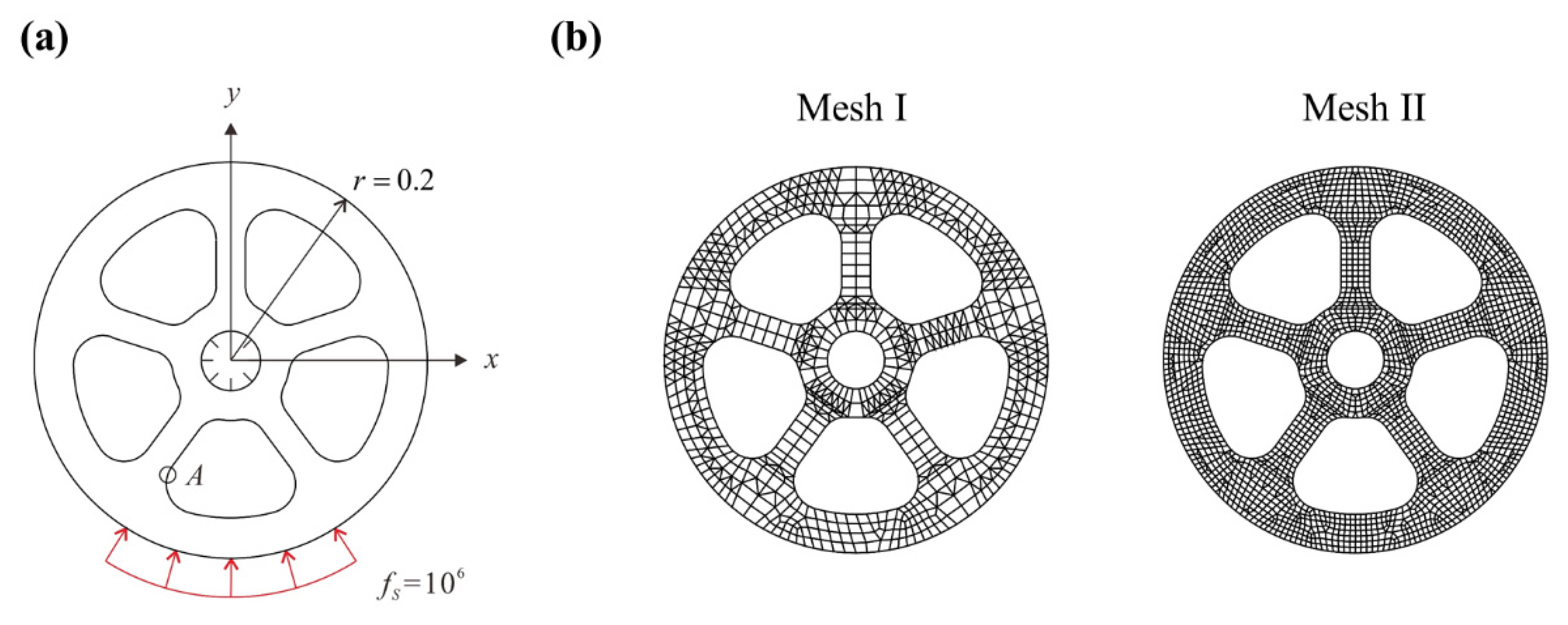
We here consider the problem of an automotive wheel with a radius of 0.2 (see Figure 11). The lower part of the wheel is subjected to a constant pressure load and the fixed boundary condition is imposed on the inner circle. The plane stress condition with and , and two different meshes (Mesh I and II) shown in Figure 11 are used.
Figure 11.
Automotive wheel problem: (a) Problem description. (b) Sequence of meshes (Mesh I, II, and III) used.
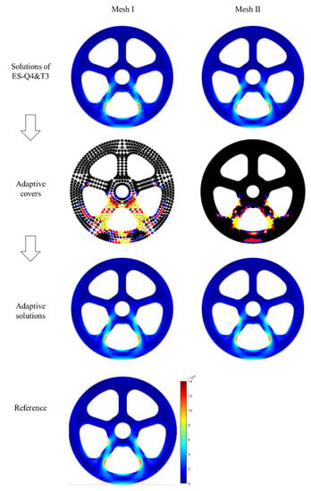
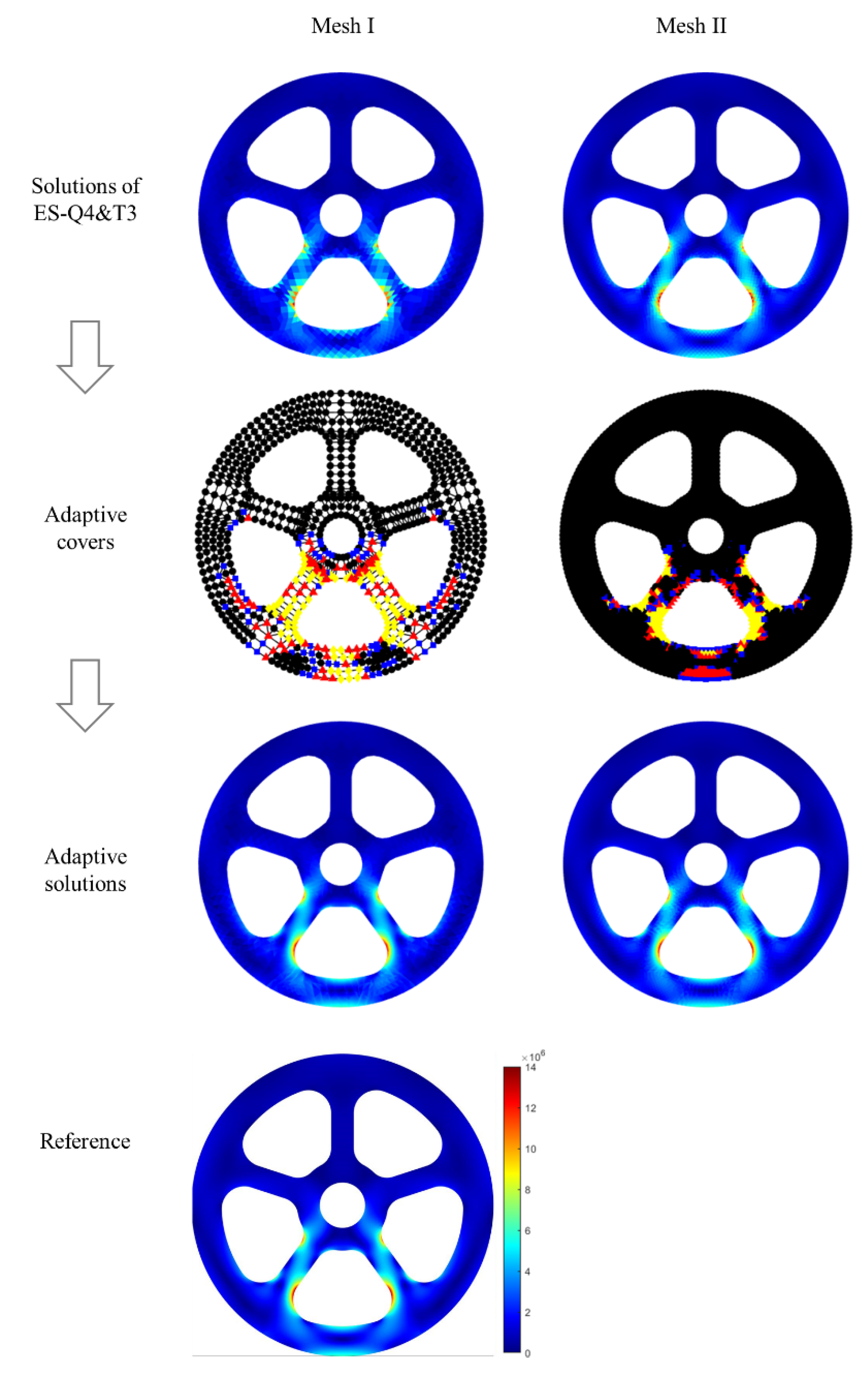
Numerical results obtained employing the edge-based smoothed finite elements (ES-FE) are compared with the results of the adaptive enrichment scheme. Table 4 gives the relative errors in the energy norm in Equation (27) and maximum von Mises stress that are averaged stress values at each node in Equation (26). The von Mises stress distributions are given in Figure 12 and the reference solutions are obtained employing a mesh of 9058 nine-node quadrilateral elements.
Table 4.
Relative errors (%) in the energy norm () and the maximum von Mises stress () at point A in the wheel problem.
Figure 12.
von Mises () predictions obtained by the edge-based smoothed elements (ES-Q4, ES-T3) and the proposed adaptive enrichment scheme for the wheel problem shown in Figure 11.
The proposed scheme applies the cover functions to the area where the solution accuracy needs to be improved and there is high stress gradient. Thus, the increase of the number of DOFs could be minimized, and the accuracy of the strain energy and the maximum von Mises stress prediction is improved.
3.4. L-Shape Structure Problem
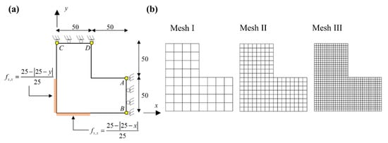
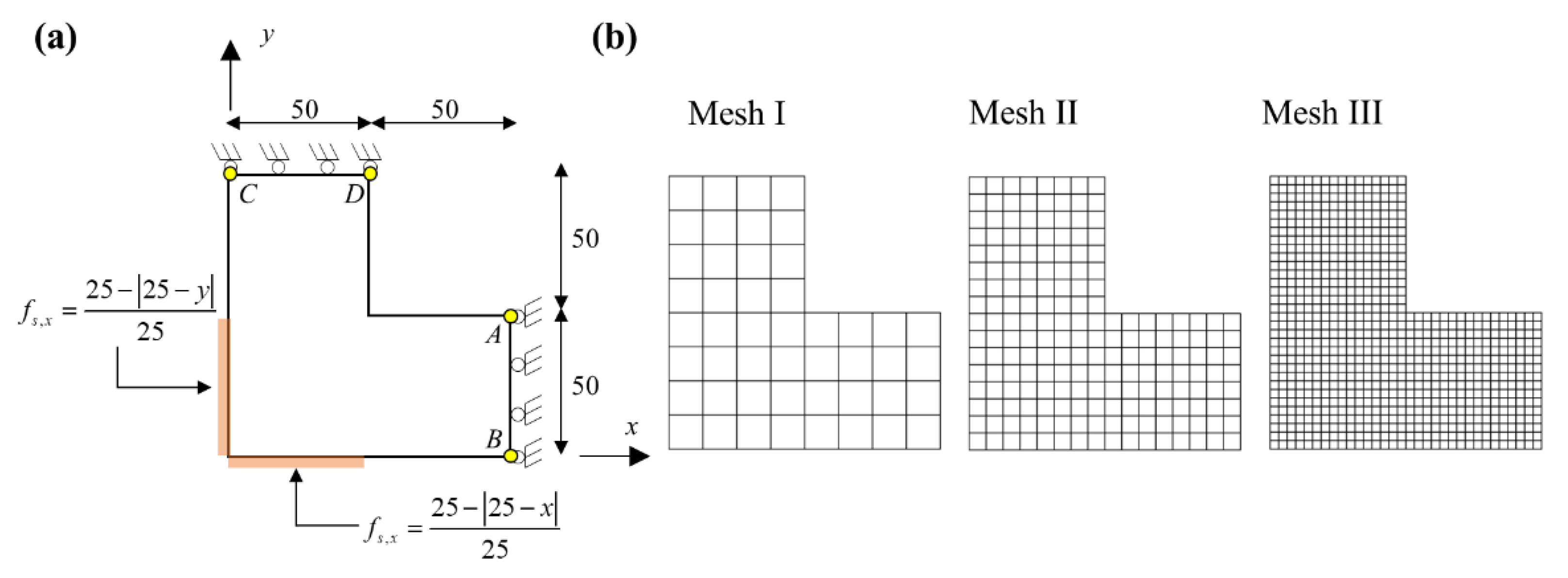
The L-shape structure is subjected to pressure load varying along the edges, as shown in Figure 13 and the boundary conditions are imposed as: along AD and along CD. The plane stress condition is used with material properties and .
Figure 13.
Automotive wheel problem: (a) Problem description. (b) Sequence of meshes (Mesh I, II, and III) used.
The finite element models are constructed using the standard four-node and three-node elements (ST-Q4, ST-T3) and the edge-based smoothed four-node and four-node elements (ES-Q4, ES-T3) for three different meshes (Mesh I, II, III), as shown in Figure 13. Triangular element meshes are generated from the quadrilateral mesh by dividing each quadrilateral element into two triangular elements. To obtain an improved solution, the enrichment schemes for the ST-FE and ES-FE are employed, and accuracy improvement and computational efficiency in terms of the number of DOFs used are compared. The reference solutions are calculated using a mesh of 3072 nine-node quadrilateral elements.
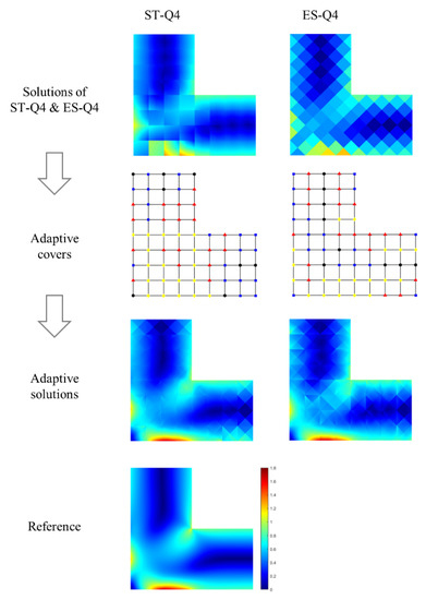
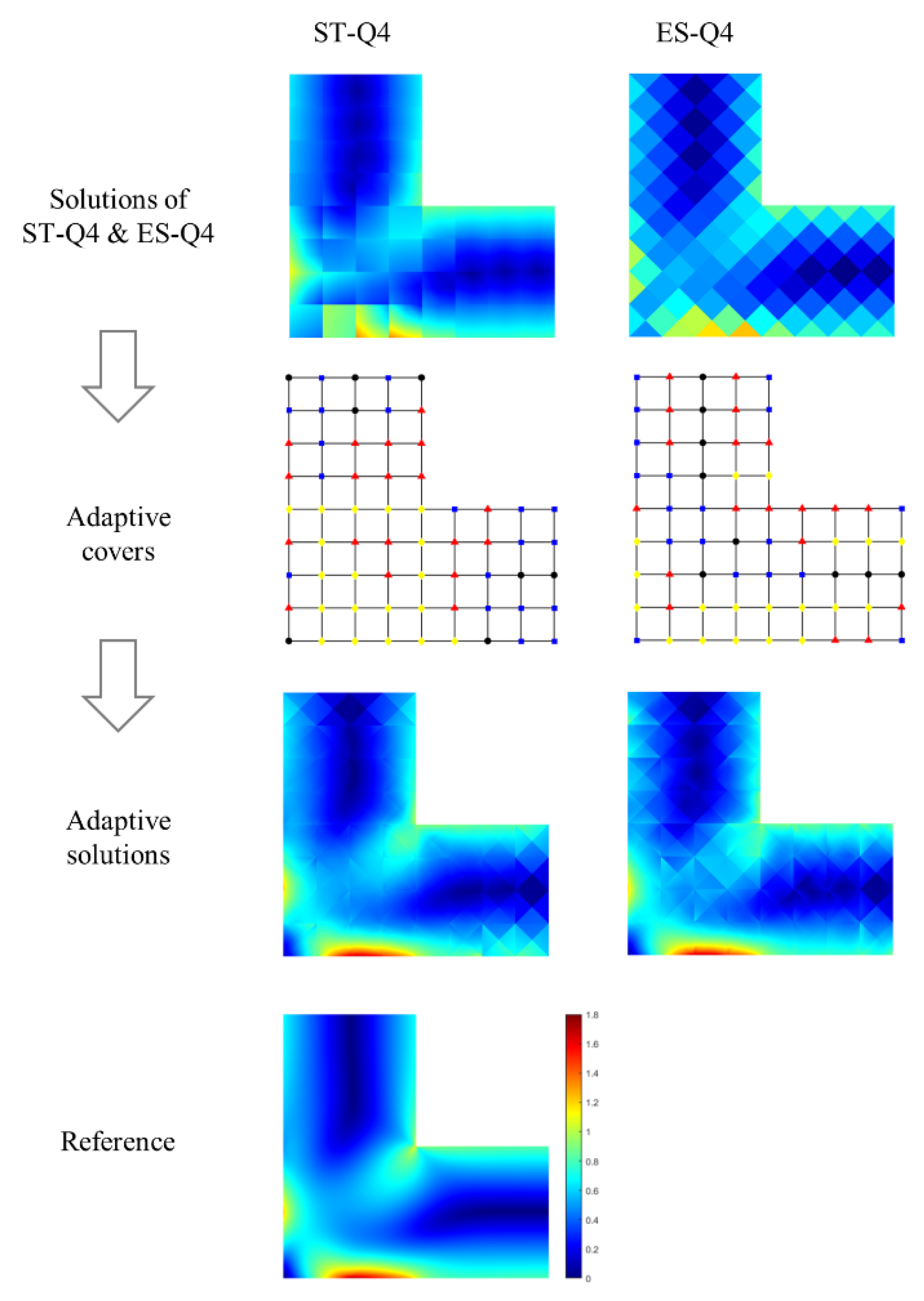
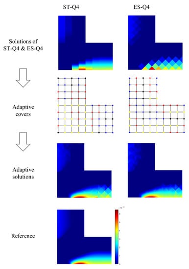
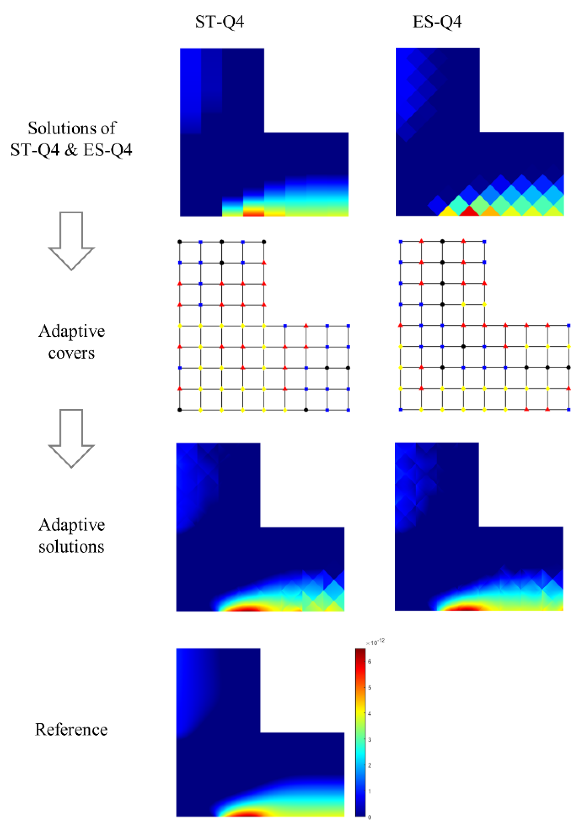
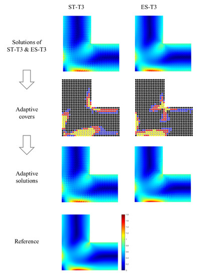
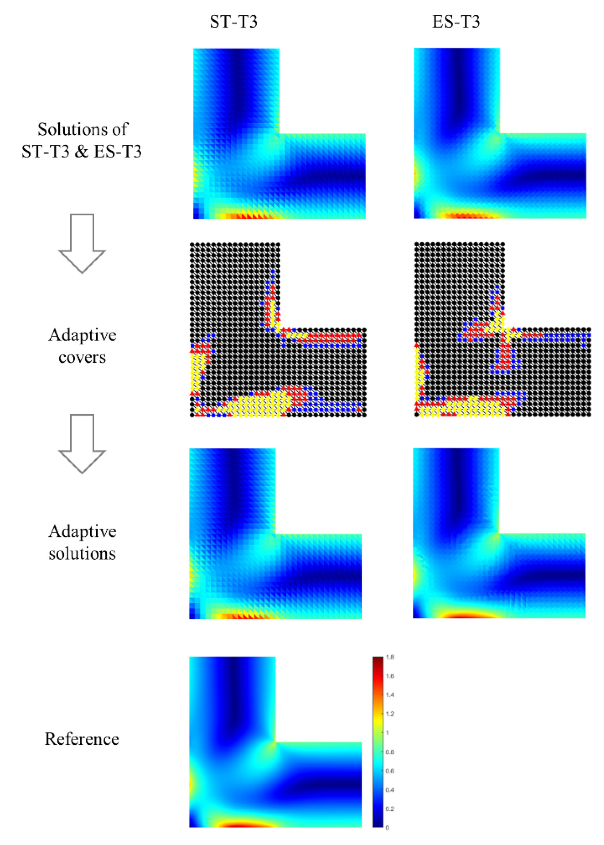
The von Mises stress fields and the strain component obtained from the linear elements and adaptive enrichment scheme are presented in Figure 14, Figure 15 and Figure 16, and the relative errors of strain energy and maximum von Mises stress are summarized in Table 5 and Table 6.
Figure 14.
von Mises () predictions obtained by the standard and edge-based smoothed four-node quadrilateral finite elements (ST-Q4 and ES-Q4) and the adaptive enrichment scheme for the L-shape structure problem when the Mesh I is used.
Figure 15.
Strain () predictions obtained by the standard and edge-based smoothed four-node triangular finite elements (ST-Q4 and ES-Q4) and the adaptive enrichment scheme for the L-shape structure problem when the Mesh I is used.
Figure 16.
Von Mises () predictions obtained by the standard and edge-based smoothed four-node triangular finite elements (ST-T3 and ES-T3) and the adaptive enrichment scheme for the L-shape structure problem when the Mesh III is used.
Table 5.
Relative errors (%) in the energy norm () and the maximum von Mises stress () in the L-shape structure problem when the meshes of quadrilateral elements (ST-Q4, ES-Q4) are used.
Table 6.
Relative errors (%) in the energy norm () and the maximum von Mises stress () in the L-shape structure problem when the meshes of triangular elements (ST-T3, ES-T3) are used.
As for the quadrilateral mesh, the ES-Q4 provides greatly improved strain energy prediction compared to the ST-Q4, whereas the ES-Q4 appears to be less accurate in predicting the maximum von Mises stress. By applying the suggested procedure, the solution of the ES-Q4 is significantly improved, especially in stress prediction, and the increase of DOFs used is less than the ST-Q4, as seen in Table 5. For the triangular mesh, the ES-T3 provides more accurate results than the ST-T3 for the same mesh. Therefore, when the same procedure is applied, the smaller number of DOFs is used for the ES-T3, but sufficiently accurate results are provided (see Table 6).
4. Conclusions
The objective of this paper was to propose an adaptive enrichment scheme for the edge-based smoothed 2D solid finite elements to effectively obtain a solution with desired accuracy. When the edge-based smoothed finite elements provide a solution that is not sufficiently converged, the suggested error indicator estimates the error for each node. Then, the cover function selection scheme assigns the polynomial cover functions of the appropriate degrees (up to a cubic degree) for each node. In order to apply the cover function, enriched finite elements free from the linear dependence problem were adopted, and the strain smoothing scheme was applied only to the area that is not subject to the applied cover function. Through this procedure, analysis accuracy can be automatically improved without mesh-refinement or introducing additional nodes, and a high-gradient solution can be effectively captured.
The performance of the proposed procedure is demonstrated through several numerical examples. In each example, the procedure selected the appropriate nodes located in an area where solution accuracy needs to be ameliorated, and the strain energy, stress, strain, and displacement predictions were enhanced effectively. In future work, it would be valuable to extend an adaptive enrichment scheme for nonlinear analysis to enhance the convergence performance in iterative analysis. In addition, the adaptive enrichment scheme can be easily applied to the 3D solid, shell, and beam finite elements [33,36,37,38,39,40].
Author Contributions
Conceptualization, S.K. and M.-H.O.; methodology, S.K.; software, S.K.; investigation, S.K. and M.-H.O.; writing—original draft preparation, S.K. All authors have read and agreed to the published version of the manuscript.
Funding
This research was supported by the National Research Foundation of Korea (NRF) grant funded by the Korea government (MSIT) (No. NRF-2020R1G1A1006911).
Institutional Review Board Statement
Not applicable.
Informed Consent Statement
Not applicable.
Data Availability Statement
Not applicable.
Acknowledgments
The authors appreciate the support of the National Research Foundation of Korea (NRF) grant funded by the Korea government.
Conflicts of Interest
The authors declare no conflict of interest.
References
- Zienkiewicz, O.C.; Taylor, R.L. The Finite Element Method, 5th ed.; Butterworth-Heinemann: Oxford, UK, 2000. [Google Scholar]
- Bathe, K.J. Finite Element Procedure; Prentice Hall: New York, NY, USA, 1996. [Google Scholar]
- Hughes, T.J.R. The Finite Element Method-Linear Static and Dynamic Finite Element Analysis; Dover Publications: New York, NY, USA, 2000. [Google Scholar]
- Cook, R.D. Concepts and Applications of Finite Element Analysis; John Wiley & Sons: New York, NY, USA, 2007. [Google Scholar]
- Babuska, I.; Melenk, J.M. The Partition of Unity Method. Int. J. Numer. Methods Eng. 1996, 40, 727–758. [Google Scholar] [CrossRef]
- Liu, G.R. The smoothed finite element method (S-FEM): A framework for the design of numerical models for desired solutions. Front. Struct. Civ. Eng. 2019, 13, 456–477. [Google Scholar] [CrossRef] [Scilit]
- Bek, Y.K.; Hamdia, K.M.; Rabczuk, T.; Könke, C. Micromechanical model for polymeric nano-composites material based on SBFEM. Comp. Struct. 2018, 194, 516–526. [Google Scholar]
- Fries, T.P.; Belytschko, T. The extended/generalized finite element method: An overview of the method and its applications. Int. J. Numer. Methods Eng. 2010, 84, 253–304. [Google Scholar] [CrossRef] [Scilit]
- Ham, S.; Bathe, K.J. A finite element method enriched for wave propagation problems. Comput. Struct. 2012, 94, 1–12. [Google Scholar] [CrossRef] [Scilit]
- Hong, W.T.; Lee, P.S. Coupling flat-top partition of unity method and finite element method. Finite Elem. Anal. Des. 2013, 67, 43–55. [Google Scholar] [CrossRef] [Scilit]
- Kim, J.; Bathe, K.J. The finite element method enriched by interpolation covers. Comput. Struct. 2013, 116, 35–49. [Google Scholar] [CrossRef] [Scilit]
- Chen, J.S.; Wu, C.T.; Yoon, S.; You, Y. A stabilized conforming nodal integration for Galerkin mesh-free methods. Int. J. Numer. Methods Eng. 2001, 50, 435–466. [Google Scholar] [CrossRef] [Scilit]
- Liu, G.R.; Dai, K.Y.; Nguyen, T.T. A smoothed finite element method for mechanics problems. Comput. Mech. 2007, 39, 859–877. [Google Scholar] [CrossRef] [Scilit]
- Nguyen-Thoi, T.; Phung-Van, P.; Thai-Hoang, C.; Nguyen-Xuan, H. A cell-based smoothed discrete shear gap method (CS-DSG3) using triangular elements for static and free vibration analyses of shell structures. Int. J. Mech. Sci. 2013, 74, 32–45. [Google Scholar] [CrossRef] [Scilit]
- Hamrani, A.; Habib, S.H.; Belaidi, I. CS-IGA: A new cell-based smoothed isogeometric analysis for 2D computational mechanics problems. Comput. Methods Appl. Mech. Eng. 2017, 315, 671–690. [Google Scholar] [CrossRef] [Scilit]
- Liu, G.R.; Nguyen-Thoi, T.; Nguyen-Xuan, H.B.; Lam, K.Y. A node-based smoothed finite element method (NS-FEM) for upper bound solutions to solid mechanics problems. Comput. Struct. 2009, 87, 14–26. [Google Scholar] [CrossRef] [Scilit]
- Nguyen-Thoi, T.; Vu-Do, H.C.; Rabczuk, T.; Nguyen-Xuan, H. A node-based smoothed finite element method (NS-FEM) for upper bound solution to visco-elastoplastic analyses of solids using triangular and tetrahedral meshes. Comput. Methods Appl. Mech. Eng. 2010, 199, 3005–3027. [Google Scholar] [CrossRef] [Scilit]
- Liu, G.R.; Nguyen-Thoi, T.; Lam, K.Y. An edge-based smoothed finite element method (ES-FEM) for static, free and forced vibration analyses of solids. J. Sound Vib. 2009, 320, 1100–1130. [Google Scholar] [CrossRef] [Scilit]
- He, Z.C.; Liu, G.R.; Zhong, Z.H.; Wu, S.C.; Zhang, G.Y.; Cheng, A.G. An edge-based smoothed finite element method (ES-FEM) for analyzing three-dimensional acoustic problems. Comput. Methods Appl. Mech. Eng. 2009, 199, 20–33. [Google Scholar] [CrossRef] [Scilit]
- Chen, L.; Rabczuk, T.; Bordas, S.P.A.; Liu, G.R.; Zeng, K.Y.; Kerfriden, P. Extended finite element method with edge-based strain smoothing (ESm-XFEM) for linear elastic crack growth. Comput. Methods Appl. Mech. Eng. 2012, 209, 250–265. [Google Scholar] [CrossRef] [Scilit]
- Lee, C.; Kim, H.; Im, S. Polyhedral elements by means of node/edge-based smoothed finite element method. Int. J. Numer. Methods Eng. 2017, 110, 1069–1100. [Google Scholar] [CrossRef] [Scilit]
- Lee, C.; Kim, H.; Kim, J.; Im, S. Polyhedral elements using an edge-based smoothed finite element method for nonlinear elastic deformations of compressible and nearly incompressible materials. Comput. Mech. 2017, 60, 659–682. [Google Scholar] [CrossRef] [Scilit]
- Nguyen-Thoi, T.; Liu, G.R.; Lam, K.Y.; Zhang, G.Y. A face-based smoothed finite element method (FS-FEM) for 3D linear and geometrically non-linear solid mechanics problems using 4-node tetrahedral elements. Int. J. Numer. Methods Eng. 2009, 78, 324–353. [Google Scholar] [CrossRef] [Scilit]
- Nguyen-Thoi, T.; Liu, G.R.; Vu-Do, H.C.; Nguyen-Xuan, H. A face-based smoothed finite element method (FS-FEM) for visco-elastoplastic analyses of 3D solids using tetrahedral mesh. Comput. Methods Appl. Mech. Eng. 2009, 198, 3479–3498. [Google Scholar] [CrossRef] [Scilit]
- Lee, C.; Lee, P.S. A new strain smoothing method for triangular and tetrahedral finite elements. Comput. Methods Appl. Mech. Eng. 2018, 341, 939–955. [Google Scholar] [CrossRef] [Scilit]
- Lee, C.; Lee, P.S. The strain-smoothed MITC3+ shell finite element. Comput. Struct. 2019, 223, 106096. [Google Scholar] [CrossRef] [Scilit]
- An, X.M.; Li, L.X.; Ma, G.W.; Zhang, H.H. Prediction of rank deficiency in partition of unity-based methods with plane triangular or quadrilateral meshes. Comput. Methods Appl. Mech. Eng. 2011, 200, 665–674. [Google Scholar] [CrossRef] [Scilit]
- An, X.M.; Zhao, Z.Y.; Zhang, H.H.; Li, L.X. Investigation of linear dependence problem of three-dimensional partition of unity-based finite element methods. Comput. Methods Appl. Mech. Eng. 2012, 233, 137–151. [Google Scholar] [CrossRef] [Scilit]
- Oden, J.T.; Duarte, C.A.M.; Zienkiewicz, O.C. A new cloud-based hp finite element method. Comput. Methods Appl. Mech. Eng. 1998, 153, 117–126. [Google Scholar] [CrossRef] [Scilit]
- Strouboulis, T.; Babuška, I.; Copps, K. The design and analysis of the generalized finite element method. Comput. Methods Appl. Mech. Eng. 2020, 181, 43–69. [Google Scholar] [CrossRef] [Scilit]
- Tian, R.; Yagawa, G.; Terasaka, H. Linear dependence problems of partition of unity-based generalized FEMs. Comput. Methods Appl. Mech. Eng. 2006, 195, 4768–4782. [Google Scholar] [CrossRef] [Scilit]
- Kim, S.; Lee, P.S. A new enriched 4-node 2D solid finite element free from the linear dependence problem. Comput. Struct. 2018, 202, 25–43. [Google Scholar] [CrossRef] [Scilit]
- Kim, S.; Lee, P.S. New enriched 3D solid finite elements: 8-node hexahedral, 6-node prismatic, and 5-node pyramidal elements. Comput. Struct. 2019, 216, 40–63. [Google Scholar] [CrossRef] [Scilit]
- Kim, J.; Bathe, K.J. Towards a procedure to automatically improve finite element solutions by interpolation covers. Comput. Struct. 2014, 131, 81–97. [Google Scholar] [CrossRef] [Scilit]
- Lee, C.; Kim, S. Towards improving finite element solutions automatically with enriched 2D solid elements. Struct. Eng. Mech. 2020, 76, 379–393. [Google Scholar]
- Jeon, H.M.; Lee, P.S.; Bathe, K.J. The MITC3 shell finite element enriched by interpolation covers. Comput. Struct. 2014, 134, 128–142. [Google Scholar] [CrossRef] [Scilit]
- Chau-Dinh, T.; Nguyen-Duy, Q.; Nguyen-Xuan, H. Improvement on MITC3 plate finite element using edge-based strain smoothing enhancement for plate analysis. Acta Mech. 2017, 228, 2141–2163. [Google Scholar] [CrossRef] [Scilit]
- Jun, H.; Yoon, K.; Lee, P.S.; Bathe, K.J. The MITC3+ shell element enriched in membrane displacements by interpolation covers. Comput. Methods Appl. Mech. Eng. 2018, 337, 458–480. [Google Scholar] [CrossRef] [Scilit]
- Yoon, K.; Lee, Y.; Lee, P.S. A continuum mechanics based 3-D beam finite element with warping displacements and its modeling capabilities. Struct. Eng. Mech. 2012, 43, 411–437. [Google Scholar] [CrossRef] [Scilit]
- Kim, H.J.; Yoon, K.; Lee, P.S. Continuum mechanics based beam elements for linear and nonlinear analyses of multi-layered composite beams with interlayer slips. Compo. Struct. 2020, 235, 111740. [Google Scholar] [CrossRef] [Scilit]

Publisher’s Note: MDPI stays neutral with regard to jurisdictional claims in published maps and institutional affiliations. |
© 2021 by the authors. Licensee MDPI, Basel, Switzerland. This article is an open access article distributed under the terms and conditions of the Creative Commons Attribution (CC BY) license (https://creativecommons.org/licenses/by/4.0/).