


Abstract
Fault waviness can control whether earthquakes arrest, cascade, or transition to supershear rupture, yet its interaction with hypocentral position and free-surface proximity remains poorly constrained. We use three-dimensional spontaneous dynamic-rupture simulations of a vertical right-lateral fault containing one symmetric undulation. Its along-strike length L, transverse height H, signed nucleation distance, and upper-edge burial are varied under uniform regional stress and slip-weakening friction. Resolving the stress onto the non-planar surface creates a directional barrier–asperity pair. In surface-breaking models, small undulations permit cascading and sustained supershear rupture for all tested hypocenters, whereas larger undulations increasingly arrest rupture. The maximum height that permits position-independent cascading increases with undulation length, while the corresponding one-sided bend angle decreases from about 32° at L = 4 km to about 14° at L = 14–18 km. Burial suppresses shallow free-surface-induced supershear and narrows the cascading regime, but transmitted ruptures can still develop sustained or transient supershear at depth. Greater hypocentral distance generally favors transmission without monotonically favoring sustained supershear. These results show that fault geometry, rupture approach direction, hypocentral position, and surface proximity jointly control rupture connectivity and speed.
1. Introduction
Large strike-slip earthquakes rupture fault systems whose traces and seismogenic surfaces contain bends, stepovers, branches, and multiscale roughness. These features are not merely geometric descriptors. By rotating the local fault plane relative to the regional stress tensor, they modify normal and shear tractions, change the local strength excess, scatter seismic waves, and redistribute energy around a propagating rupture front. They can therefore arrest rupture, transfer it to another segment, or accelerate it into a new rupture regime. Dynamic models of branched, stepped, barrier-bearing, and rough faults show that geometry, prestress, and propagation direction must be evaluated together [1,2,3,4,5,6,7,8]. Recent near-fault observations and dynamic simulations further show that fault bends can modulate rupture deceleration and transient supershear propagation [9].
Geological and geophysical observations show that wave-like or double-bend structures occur on active faults, although their three-dimensional forms differ. The Aksay restraining double bend on the Altyn Tagh Fault in northern Tibet comprises two major strands that bend together through a broad transpressional zone [10]. Paleoseismic evidence indicates that many prehistoric ruptures terminated within the bend, whereas at least one larger event breached it, implying that the same structure can be a barrier in some earthquake cycles and transmissive in another [11]. Along the San Andreas Fault near Parkfield and Cholame, the active trace forms an approximately 50-km-long asymmetric warp; geodetic and seismological interpretations suggest that this bend is pronounced in the shallow crust and may become simpler at depth [12]. Corrugation is also documented on natural fault surfaces, including the offshore Costa Rica megathrust [13], and is associated with heterogeneous slip [14]. These examples establish the geological plausibility of broad fault waviness, while also warning that a mapped surface trace need not represent the complete seismogenic geometry.
Rupture speed is a particularly consequential outcome of geometry–stress interaction. Classical slip-weakening theory predicts transition from sub-Rayleigh to supershear rupture when the available energy and stress conditions permit a daughter crack to develop ahead of the main front [15,16]. Favorable heterogeneity can reduce the transition distance [17], while barriers and stepovers can abruptly stop or scatter the primary front, concentrate dynamic stress, and nucleate a supershear daughter rupture [4,5,6,7]. Rough-fault simulations further show that multiscale geometry changes both rupture complexity and the supershear threshold [8]. Supershear initiation and persistence are therefore distinct: a transient geometric perturbation may trigger an intersonic front that later decelerates.
Geometric complexity can also promote asymmetric or effectively unilateral rupture, linking structural orientation and propagation direction to azimuthal variations in seismic radiation and ground-motion amplitude. Recent empirical studies show that directivity is frequency dependent and can substantially affect observed ground-motion amplitudes [18,19].
Observations from real earthquakes provide increasingly clear evidence that fault geometry and spatially variable prestress jointly control rupture connectivity, propagation direction, and supershear persistence. The 2020 Mw 7.7 Caribbean earthquake propagated for nearly 300 km along the Oriente transform and included two supershear episodes separated by changes in rupture speed and direction near geometric complexity [20]. Dynamic models of the 2021 Mw 7.4 Maduo earthquake favor a unilateral, double-onset supershear rupture accompanied by cascading activation of adjacent branches, controlled jointly by fault geometry, prestress, and spatially variable fracture energy [21]. During the 2023 Kahramanmaraş, Türkiye, earthquake sequence, near-field observations and dynamic models indicate episodic supershear and cascading rupture through a geometrically complex fault network [22,23]. Subsequent studies emphasize steering by prestress heterogeneity and the role of geometric barriers in rupture and stress release [24,25]. Recent observational, kinematic, and physics-based ground-motion studies further document mixed subshear and supershear propagation modulated by complex fault geometry and the ground-motion consequences of sustained supershear and three-dimensional source complexity [9,26,27]. None of these earthquakes is an exact counterpart of a single smooth undulation, but together they demonstrate that geometry can govern both rupture connectivity and the duration of supershear propagation.
On vertical strike-slip faults that intersect the Earth’s surface, an additional mechanism operates. Reflected and converted waves can amplify shallow slip and promote a supershear transition even when the corresponding full-space rupture remains subshear [28,29]. A shallow geometric barrier may thus compete with, delay, or reinforce free-surface feedback. Curvilinear numerical methods now allow this interaction to be examined on non-planar faults while imposing friction directly on the curved surface [30], yet systematic studies have focused more often on discrete steps, branches, or roughness than on one broad, smooth wave. Unlike those configurations, the present design isolates a single smooth undulation and jointly varies its geometric scale, rupture-approach direction, nucleation distance, and proximity to the free surface.
However, the combined effects of the scale of a single broad undulation, signed rupture approach, hypocentral run-up distance, and free-surface proximity have not been mapped systematically within one controlled model family. The present study fills this gap by isolating these coupled controls and by distinguishing rupture transmission from the initiation and persistence of supershear rupture.
Here we isolate that elementary geometry. We use three-dimensional spontaneous dynamic-rupture simulations to determine how the along-strike length and transverse height of one symmetric fault undulation interact with signed hypocentral distance and upper-edge burial. Each simulation is classified as partial rupture, full subshear rupture, sustained full supershear rupture, or supershear-to-subshear rupture. The design addresses three questions: (1) when does a smooth undulation arrest or transmit rupture; (2) how does propagation direction through a geometry-generated barrier–asperity pair change that threshold; and (3) how do free-surface and geometric supershear mechanisms differ? The resulting regime diagrams provide a controlled mechanical reference for interpreting rupture through broad bends and corrugations in natural strike-slip systems.
2. Materials and Methods
2.1. Fault Geometry and Parameterization
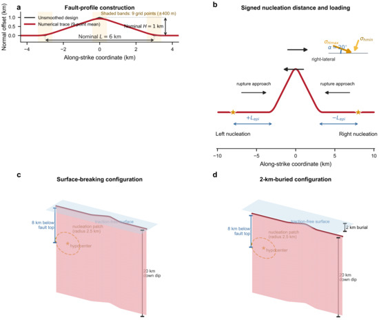
The model contains a vertical, right-lateral strike-slip fault with a single symmetric undulation in map view (Figure 1). The fault is planar away from the perturbed region and has a down-dip width of 20 km. The undulation has along-strike length and maximum transverse height . We define the one-sided bend angle as , which measures the deflection of one flank relative to the planar fault segment. This definition is used for all bend angles reported below. Five length classes are considered: , 6, 10, 14, and 18 km. For each , a series of values is tested to span ruptures that readily cross the undulation and ruptures that arrest within or adjacent to it. The total along-strike fault length is selected such that, for the most distant hypocentral position, the hypocenter is at least 10 km from the nearest along-strike fault boundary. The one-sided bend angle increases with , so provides a compact measure of geometric severity.
Figure 1.
Construction and three-dimensional configuration of the modeled fault. (a) The black line shows the original piecewise-linear design and the red line the locally smoothed trace used to construct the numerical fault grid; smoothing extends 400 m on either side of each junction, corresponding to a centered nine-point window for the 100 m grid. L and H denote the nominal dimensions of the unsmoothed design. (b) Signed along-strike hypocentral distance: +Lepi denotes nucleation on the left and −Lepi nucleation on the right. (c) Surface-breaking and (d) 2 km-buried configurations. The hypocenter is fixed 8 km below the fault upper edge, and the circular nucleation patch has a radius of 2.5 km. The traction-free surface remains present in both configurations.
The initial fault trace was defined as a symmetric piecewise-linear undulation with nominal along-strike length L and height H. To remove geometric singularities at the segment junctions, the trace was locally smoothed over 400 m on either side of each junction. With the adopted 100 m grid spacing, this corresponds to a centered nine-point smoothing window. The smoothed trace, rather than the original piecewise-linear trace, was used to construct the numerical fault grid. L and H therefore denote the nominal dimensions of the unsmoothed design geometry (Figure 1a).
The sampled L and H values were chosen to span kilometer-scale broad bends and to bracket the transition between rupture transmission and arrest, rather than to reproduce one specific natural fault. Cases with lower H/L approximate broad, gently curved natural warps, whereas the higher-H/L cases deliberately sample stronger, near-critical geometric barriers. Natural faults may additionally contain asymmetry, branches, multiscale roughness, and depth variation that are not represented in this controlled parameterization.
The nucleation patch lies on a planar portion of the fault. Its position is described by , the along-strike distance from the hypocenter to the nearest edge of the undulation. Positive values denote nucleation on the left side of the model geometry, whereas negative values denote nucleation on the right side. We test , , , and km. Because the regional stress orientation is fixed, changing the sign of changes the direction in which rupture first encounters the low- and high-stress flanks of the undulation. Thus, Lepi is measured strictly along strike, not with depth; the hypocentral depth is fixed for all simulations as described in Section 2.3.
2.2. Initial Stress, Elastic Medium, and Friction
The imposed principal stresses are MPa, MPa, and MPa. Here, and denote the maximum and minimum horizontal principal stresses, respectively, and correspond to the two horizontal principal-stress axes shown in Figure 1; is the vertical principal stress and is not shown in the map view. The axis is oriented at to the planar fault segment. On the planar fault, the resulting initial normal and shear tractions are 69.36 and 25.71 MPa, respectively. The local tractions change across the undulation because the fault-normal and fault-parallel directions rotate relative to the fixed regional stress tensor. Under this loading, the left flank is relatively unfavorable for failure and acts as a geometric barrier, whereas the right flank has a higher shear-to-strength ratio and behaves as an asperity-like favorable region.
The stress magnitudes and orientation were selected to give S = 1.1 and Te = 0.4741 on the planar fault segments, enabling direct comparison with published full-space and half-space rupture phase diagrams [28,29,31,32]. The same stress state was used in every simulation to isolate the effects of geometry, rupture direction, hypocentral distance, and burial. We did not perform an additional differential-stress sweep; this restriction is stated explicitly in Section 4.7.
Accordingly, the principal stresses and α = 20° define a controlled, near-critical reference state rather than a site-specific stress inversion. The linear slip-weakening parameters follow the reference parameterization used in the planar three-dimensional rupture models [29] and are held fixed throughout the survey. The resulting regime diagrams are therefore conditional on this common stress-and-friction state.
The surrounding medium is homogeneous, isotropic, and linearly elastic, with P-wave speed km/s, S-wave speed km/s, and density g/cm3 (2670 kg/m3). These values correspond approximately to Lamé parameters GPa and Poisson’s ratio .
Fault strength follows a linear slip-weakening law. The static and dynamic friction coefficients are and , and the critical slip distance is m. Following the stress measures used in slip-weakening rupture studies, we define the seismic ratio as [15,33]
where is the initial shear stress, is the yield shear strength, is the residual shear strength, and is the compressive normal stress. We also use the dimensionless effective shear stress [29,31,32]
On the planar fault segments, and . The two measures are algebraically equivalent and permit comparison with established rupture phase diagrams for full-space and half-space strike-slip faults. The unfavorable flank does not necessarily have an initial shear traction below the dynamic frictional strength in every model. As and the one-sided bend angle increase, however, the resolved initial shear traction on this flank can decrease sufficiently that under the adopted positive-magnitude convention. Under this condition, and , while remains valid. This condition occurs in the km and km model shown in Section 3.2.
2.3. Numerical Method and Nucleation
We solve the three-dimensional elastodynamic equations using the curved-grid finite-difference method developed for non-planar rupture dynamics [30]. The simulations were performed using CGFDM, an open-source three-dimensional dynamic-rupture solver based on the curved-grid finite-difference method. The source code is publicly available at https://github.com/Zijia-Wang/CGFDM; accessed on 5 August 2026 (archived at https://doi.org/10.5281/zenodo.13819495). The grid conforms to the fault geometry, allowing the friction law to be imposed directly on the curved fault surface. The spatial grid interval is 100 m, and the time step is 0.01 s.
To assess grid convergence, the complete buried-fault suite with L = 6 km and H = 1 km was repeated using a refined grid spacing of 50 m for all eight signed hypocentral distances, Lepi = ±5, ±10, ±20, and ±30 km. The 50 m simulations reproduced the rupture-outcome classification of every corresponding 100 m model, including partial rupture, full subshear rupture, sustained supershear rupture, and supershear-to-subshear rupture. The principal rupture-speed patterns and rupture-time contours were also consistent. The corresponding 100 m and 50 m results are compared in Supporting Figure S1.
Spontaneous rupture is initiated within a circular nucleation patch of radius 2.5 km. The hypocenter is defined as the center of this patch and is located 8 km below the upper edge of the fault. The initial shear traction inside this patch is raised slightly above the static fault strength. Outside the patch, rupture evolution is governed by the prescribed initial stress and slip-weakening friction. This procedure minimizes continued artificial forcing after nucleation while allowing systematic variation of the hypocentral position. The hypocentral depth is fixed in every model; only the along-strike position relative to the undulation is varied.
2.4. Surface-Breaking and Buried Configurations
Two upper-boundary configurations are compared. In the surface-breaking configuration, the upper edge of the fault intersects a traction-free surface. Reflected and converted waves can therefore interact directly with the rupture front and promote free-surface-induced supershear transition. In the buried configuration, the top of the fault is 2 km below the free surface. This separation weakens the direct free-surface feedback on the fault and helps isolate the supershear transition caused by the geometric perturbation and the associated stress redistribution. The traction-free surface remains present in the computational domain of the buried models; the fault is not embedded in an infinite medium. Surface-reflected waves can therefore return to the fault after propagating through the 2 km overburden, although their interaction is delayed and weaker than the direct rupture–surface coupling in the surface-breaking models. The 2 km offset was not selected as a formal convergence threshold for eliminating free-surface effects, and no additional burial-depth sensitivity sweep was performed. We therefore interpret this configuration as suppressing direct rupture–surface coupling rather than removing every free-surface contribution. The planar reference provides an internal control: under the same stress and friction, the surface-breaking planar model develops a free-surface-assisted supershear transition, whereas the 2 km-buried planar model remains subshear. Additional burial depths would be required to quantify a general decay threshold.
2.5. Planar-Fault Reference Models
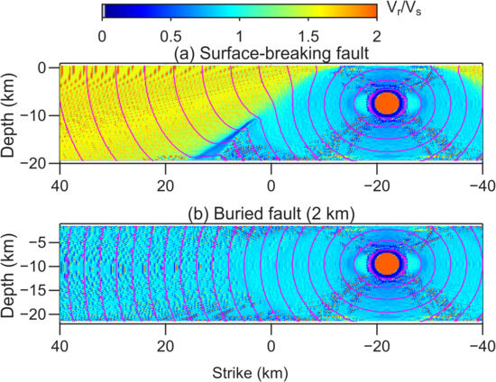
To isolate free-surface effects from those caused by the undulation, we also analyze two otherwise identical planar-fault reference models (Figure 2). One planar fault intersects the traction-free surface, whereas the upper edge of the second planar fault is buried by 2 km. Both reference models use the same elastic properties, initial stress state, friction law, grid spacing, and nucleation procedure as the non-planar simulations. Their only intended difference is the depth of the fault’s upper edge. The surface-breaking reference model therefore tests the free-surface route to supershear transition, while the buried reference model establishes the rupture-speed regime expected without direct rupture–surface interaction or non-planar geometry.
Figure 2.
Rupture speed normalized by the shear-wave speed and rupture-time contours for the planar-fault reference models. The surface-breaking planar fault develops free-surface-induced supershear rupture, whereas the otherwise equivalent planar fault with its upper edge buried by 2 km remains subshear. This comparison isolates the effect of direct interaction between the rupture and the traction-free surface.
2.6. Rupture Diagnostics and Classification
Rupture time is tracked over the fault surface and differentiated to estimate local rupture speed , which is normalized by the shear-wave speed . Rupture-time contours are plotted at 1 s intervals. The edges of the undulation are marked in each rupture map. Each simulation is assigned to one of four outcome classes:
- Partial rupture: rupture remains primarily on the nucleation side or crosses the undulation only over a short distance before arresting.
- Full subshear rupture: rupture cascades across the undulation and spans the modeled fault while remaining subshear.
- Full supershear rupture: rupture cascades across the undulation and develops sustained propagation.
- Supershear-to-subshear rupture: rupture becomes supershear after crossing the undulation but later decelerates and continues at subshear speed.
3. Results
3.1. Planar Reference Models Isolate the Free-Surface Supershear Mechanism
The two planar reference models produced different rupture-speed regimes despite sharing the same stress, friction, elastic properties, and nucleation procedure (Figure 2). On the surface-breaking planar fault, the rupture accelerated to supershear speed through interaction with the traction-free boundary. In contrast, rupture on the planar fault buried by 2 km remained subshear. Because neither reference model contains an undulation, their difference provides a direct baseline for interpreting the non-planar simulations: shallow supershear in the surface-breaking models can arise from free-surface feedback, whereas supershear in a 2 km-buried wavy-fault model requires an additional mechanism associated with non-planar geometry.
3.2. The Undulation Creates a Directional Barrier–Asperity System
Although the imposed far-field stress and friction are homogeneous, rotation of the fault surface changes the resolved tractions across the undulation. The two flanks therefore do not provide equivalent propagation paths. For the adopted right-lateral loading, the left flank has a lower shear-to-strength ratio and forms a barrier, whereas the right flank is more favorably stressed and forms an asperity-like region. Increasing H at fixed L strengthens and broadens this contrast. The evolving rupture must consequently negotiate a paired system: a favorable region that promotes rupture acceleration and localized dynamic-stress amplification and an unfavorable region that can decelerate or arrest the front.
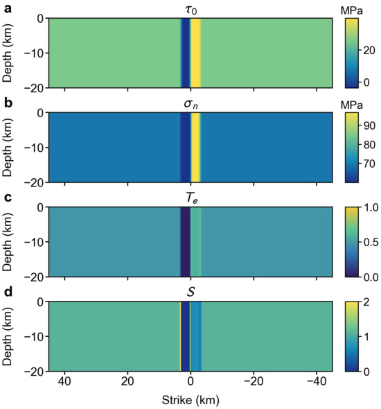
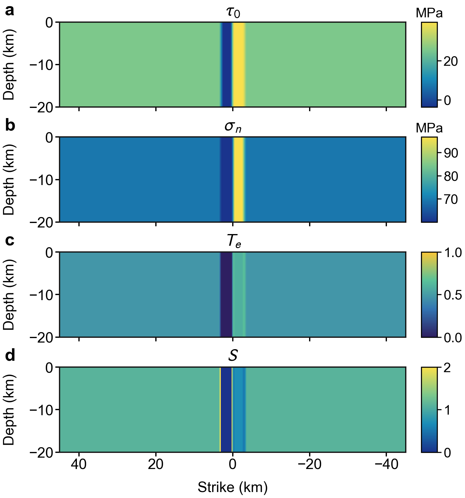
The on-fault stress and strength fields for the representative surface-breaking model with km and km illustrate this mechanically generated contrast (Figure 3). The initial shear traction and compressive normal traction depart sharply from their planar-fault values across the two flanks. In this particular model, on the barrier flank falls below the dynamic frictional strength , giving and . This strongly unfavorable initial state requires a sufficiently large dynamic stress perturbation to sustain slip. The opposite flank is more favorably loaded and behaves as an asperity-like region. The paired anomalies extend through the modeled fault width and arise from resolving the uniform regional stress onto the non-planar fault rather than from prescribed frictional heterogeneity.
Figure 3.
On-fault stress and strength distributions for the surface-breaking wavy-fault model with km and km. Panels show (a) initial shear traction , (b) compressive normal traction , (c) effective shear stress , and (d) seismic ratio . In this particular model, on the barrier flank, so both and are negative; these negative values are displayed at the lower limits of the respective color scales. The contrasting anomalies on the two flanks delineate the geometry-generated barrier–asperity pair. Depth is measured downward from the free surface. These fields describe the initial state and are independent of Lepi and hypocentral distance; no hypocentral position is assigned to Figure 3.
The sign of Lepi determines the order in which the rupture encounters these regions. Rupture nucleated on the asperity side can accelerate and develop a larger front before entering the barrier, whereas rupture arriving from the barrier side encounters the unfavorable region before reaching the asperity. This directional asymmetry becomes most visible for intermediate geometric severity, for which both full and partial ruptures occur depending on hypocentral position.
3.3. Surface-Breaking Faults: A Geometry-Dependent Cascading Threshold
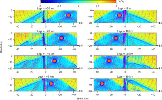
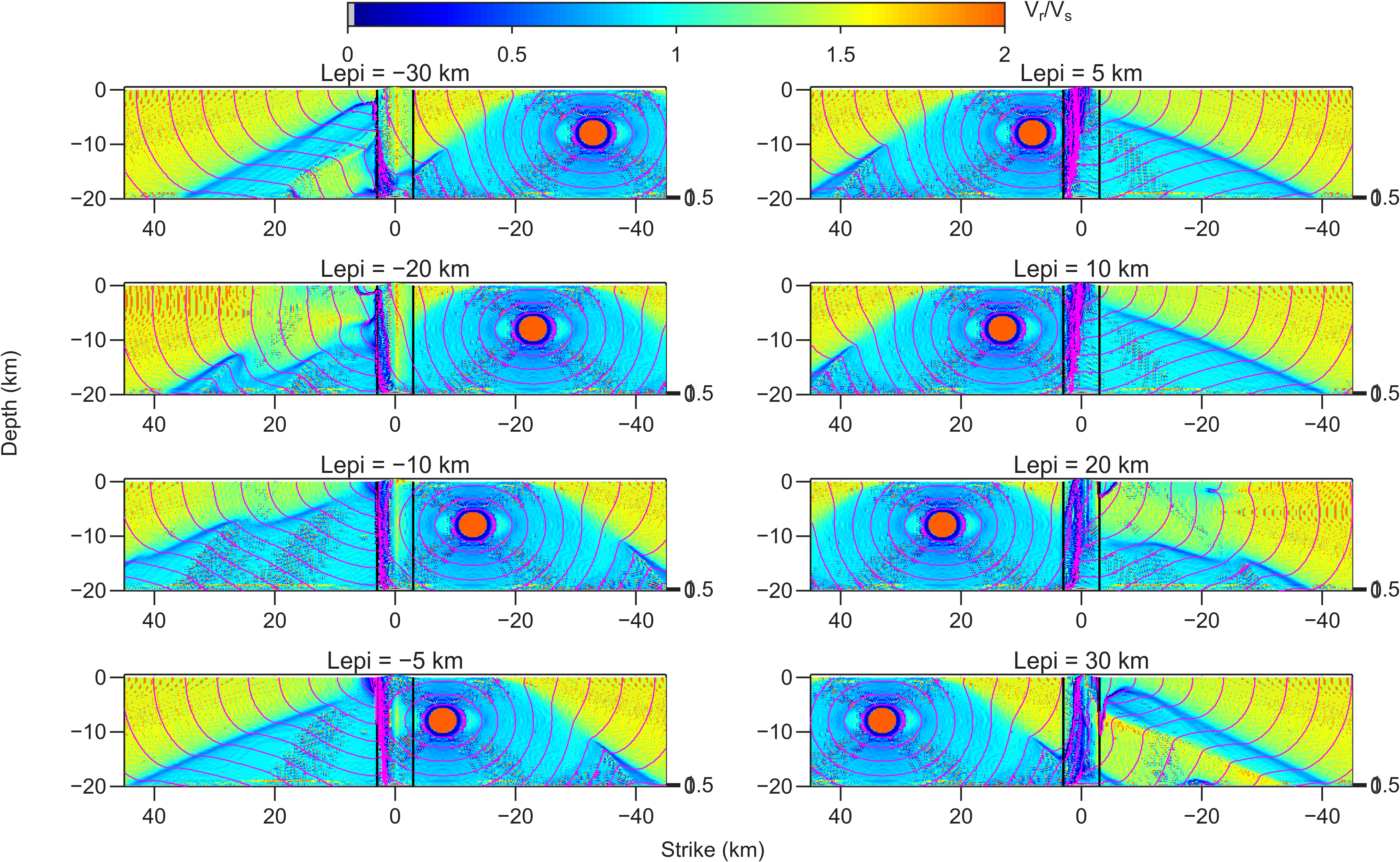
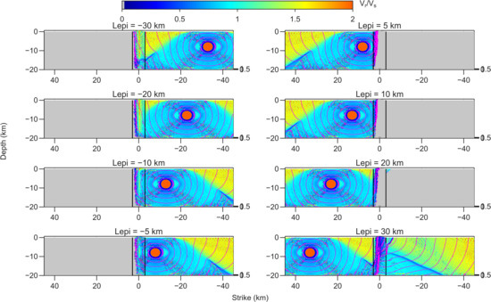
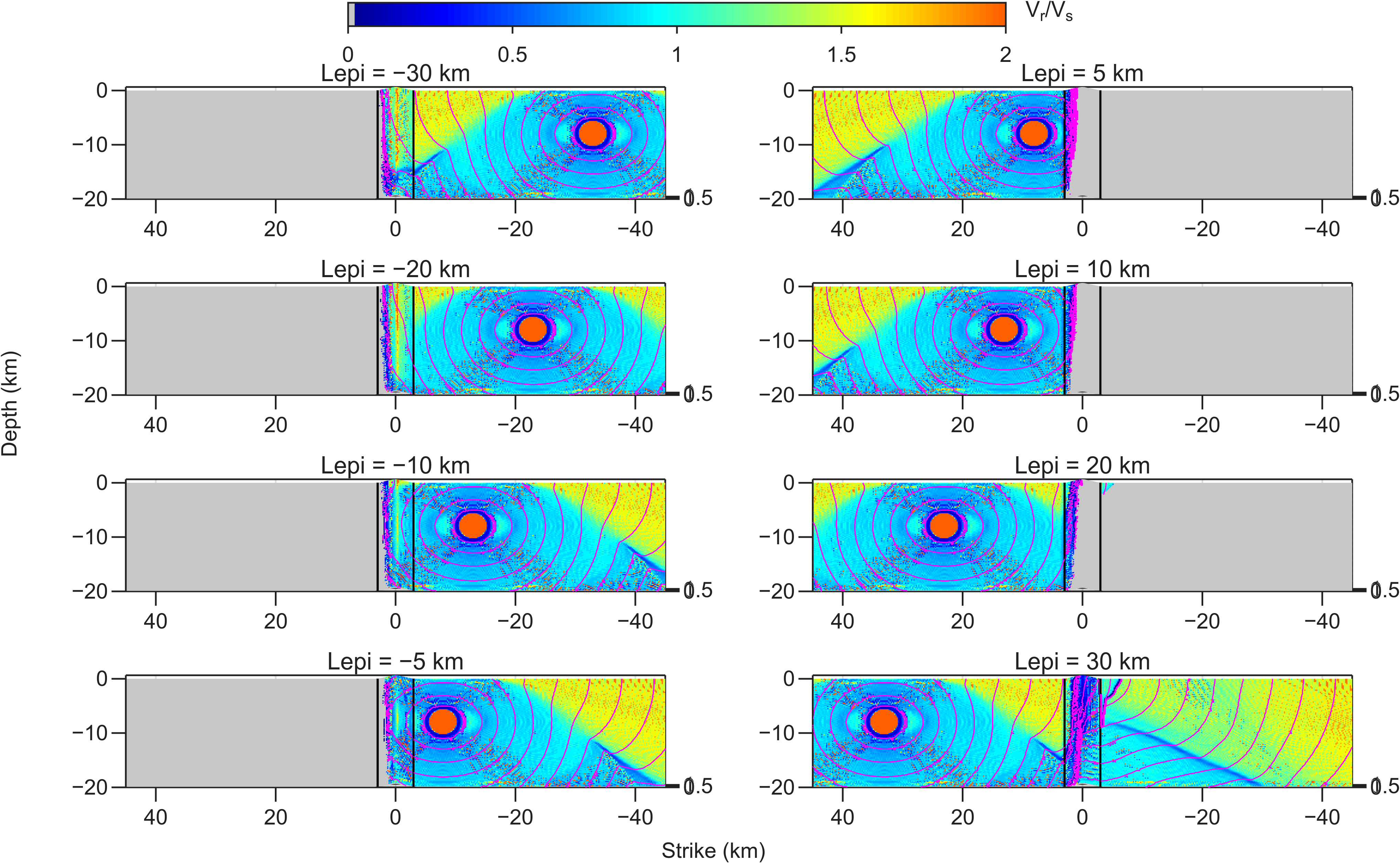
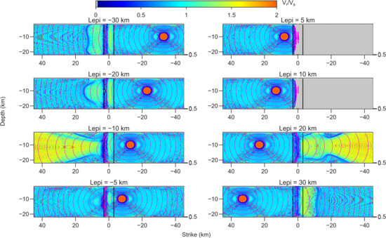
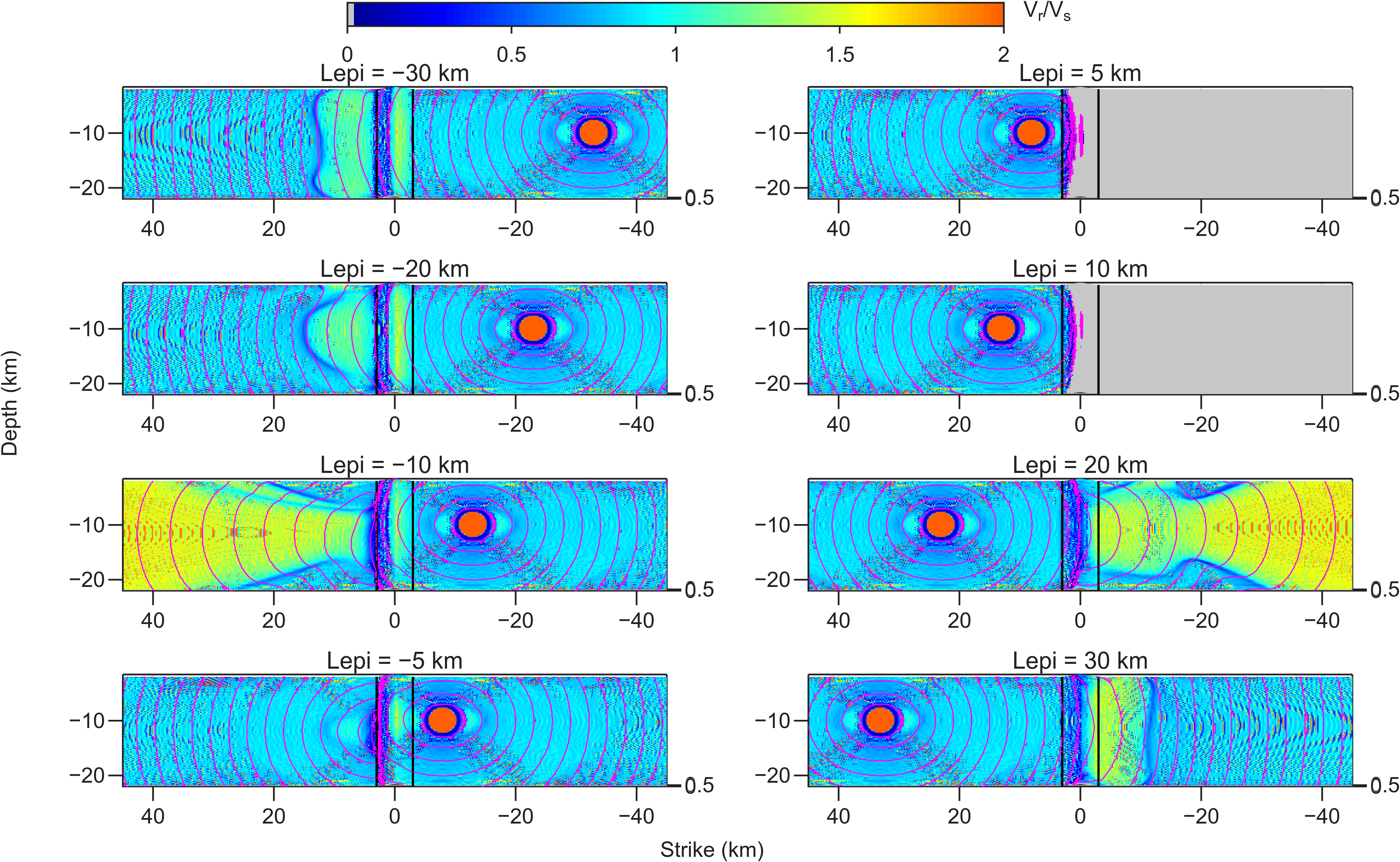
For a surface-breaking fault with km and km, all tested hypocentral positions produce cascading rupture across the undulation (Figure 4). Once rupture reaches the free surface, it develops sustained supershear propagation on the planar portions of the fault. The rupture-time contours remain continuous across the perturbed region, although their spacing and curvature change as the front interacts with the barrier–asperity pair. This case shows that a moderate undulation perturbs but does not disconnect the rupture.
Figure 4.
Rupture speed normalized by shear-wave speed and rupture-time contours for the surface-breaking model with km and km. Magenta contours are separated by 1 s; vertical black lines mark the edges of the undulation. All tested hypocentral positions produce full cascading rupture and sustained supershear propagation.
Increasing the height to km at the same length fundamentally changes the outcome (Figure 5). Most ruptures terminate on the nucleation side or shortly after entering the undulation. Full cascading rupture occurs only for a restricted distant hypocentral position. Thus, a 0.25 km change in amplitude moves the model across a connectivity threshold, demonstrating that rupture extent is highly sensitive to geometric severity near the critical regime.
Figure 5.
As in Figure 4, but for km and km. The larger undulation arrests most ruptures on the nucleation side; only a limited distant-nucleation case crosses the geometric barrier.
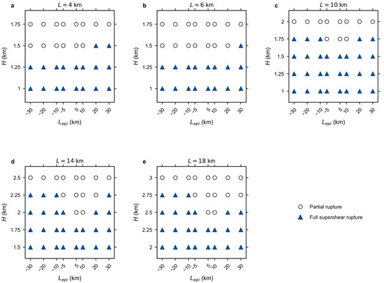
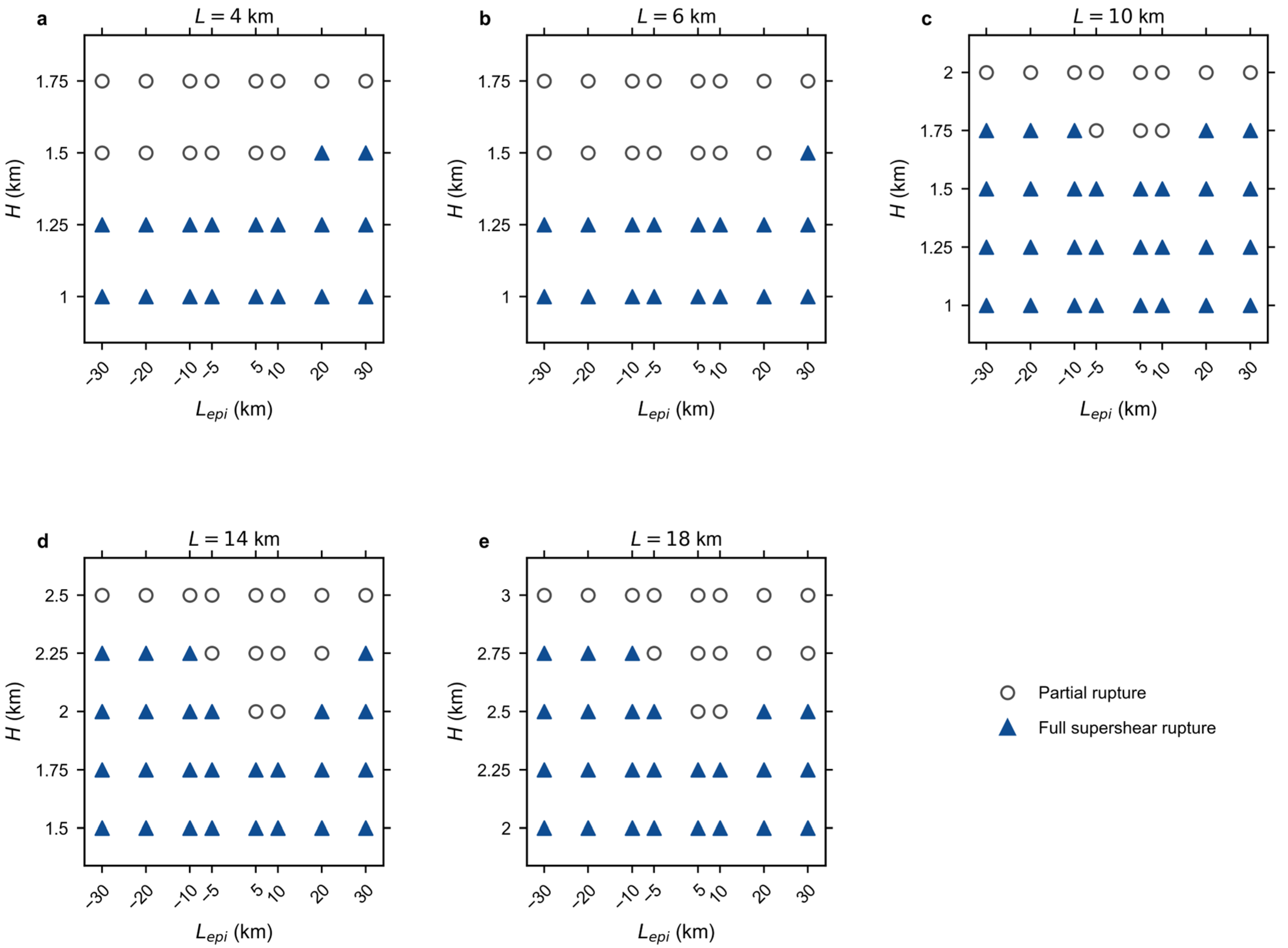
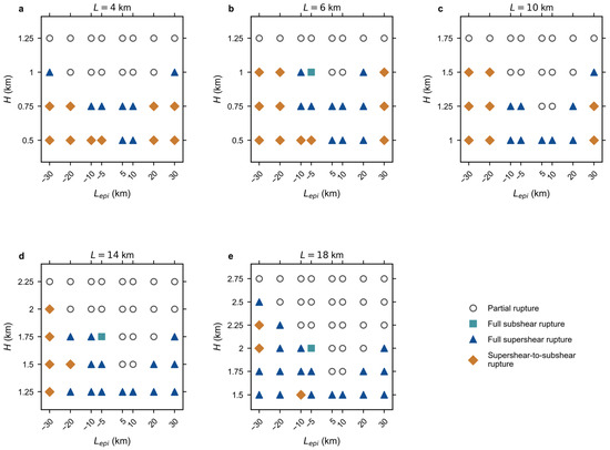
Across all five groups, the height below which every tested hypocentral position produces a full rupture increases with undulation length (Figure 6). For and 6 km, the largest position-independent cascading case has km. The corresponding values are approximately 1.5 km for km, 1.75 km for km, and 2.25 km for km. Expressed as an approximate bend angle, the limiting geometry decreases from about 32° at km to at km, at km, and about at –18 km. The threshold therefore does not collapse onto alone; both the amplitude and along-strike scale of the undulation matter.
Figure 6.
Rupture outcomes for surface-breaking faults as functions of undulation length , height , and signed hypocentral distance . Open circles denote partial rupture, and blue triangles denote full cascading rupture with sustained supershear propagation. Positive Lepi denotes nucleation on the left side of the undulation, whereas negative Lepi denotes nucleation on the right side.
At intermediate H, distant hypocenters generally promote barrier crossing. The trend is consistent with a longer acceleration distance, allowing a larger rupture front to develop before it reaches the undulation. Direction also matters: propagation from the asperity side more readily crosses the barrier in several near-critical cases, consistent with rupture acceleration and favorable dynamic-stress buildup on that flank before the front enters the unfavorable flank. At the largest H, however, the geometric barrier dominates and rupture remains confined to the nucleation side for nearly all positions.
3.4. Burial Suppresses Free-Surface Supershear but Not Supershear at Depth
Burial by 2 km changes both rupture connectivity and rupture-speed evolution. For km and km, several hypocentral positions fail to trigger rupture across the undulation, even though a larger km permits full rupture in all surface-breaking cases (Figure 7). This comparison indicates that free-surface feedback assists not only in supershear transition but also in the ability of a rupture to sustain propagation through the geometric perturbation.
Figure 7.
Rupture speed and rupture-time contours for a fault buried by 2 km with km and km. The absence of direct rupture–free-surface interaction eliminates shallow free-surface-induced supershear. Ruptures that cross the undulation may remain subshear, develop sustained supershear at depth, or transition temporarily to supershear before decelerating.
Despite the suppressed surface mechanism, the buried models still generate supershear rupture after the front crosses the undulation. The equivalent planar buried fault remains subshear for the adopted strength parameter, so the transition is consistent with a contribution from dynamic stress concentration and wave interaction associated with the barrier–asperity pair. The transition occurs at depth rather than along the upper fault edge.
Temporal diagnostics for the representative 2 km-buried model with L = 6 km, H = 1 km, and Lepi = −10 km are shown in Supporting Figure S2. As the rupture approaches and crosses the undulation between approximately 4.8 and 6.4 s, localized perturbations in shear and normal stress develop at and adjacent to the geometric flanks. A renewed high-slip-rate front subsequently propagates on the far side of the undulation between approximately 7.2 and 8.8 s. This spatial and temporal correspondence supports a contribution from geometry-related dynamic stress redistribution and wave interaction, although the snapshots do not uniquely separate these effects from the static traction contrast.
The dependence on is non-monotonic. Hypocenters very close to the undulation may fail to produce enough rupture growth to cross the barrier. Intermediate distances often produce full and sustained supershear rupture. At some of the largest distances, rupture crosses the bend and initially becomes supershear but later decelerates to subshear speed. A longer acceleration distance therefore favors connectivity, but not necessarily the maintenance of a supershear front. The sustained state depends on whether the far-side stress conditions and rupture-front state continue to support intersonic propagation after the transient geometric interaction.
3.5. Rupture-Regime Diagrams for the Buried Fault
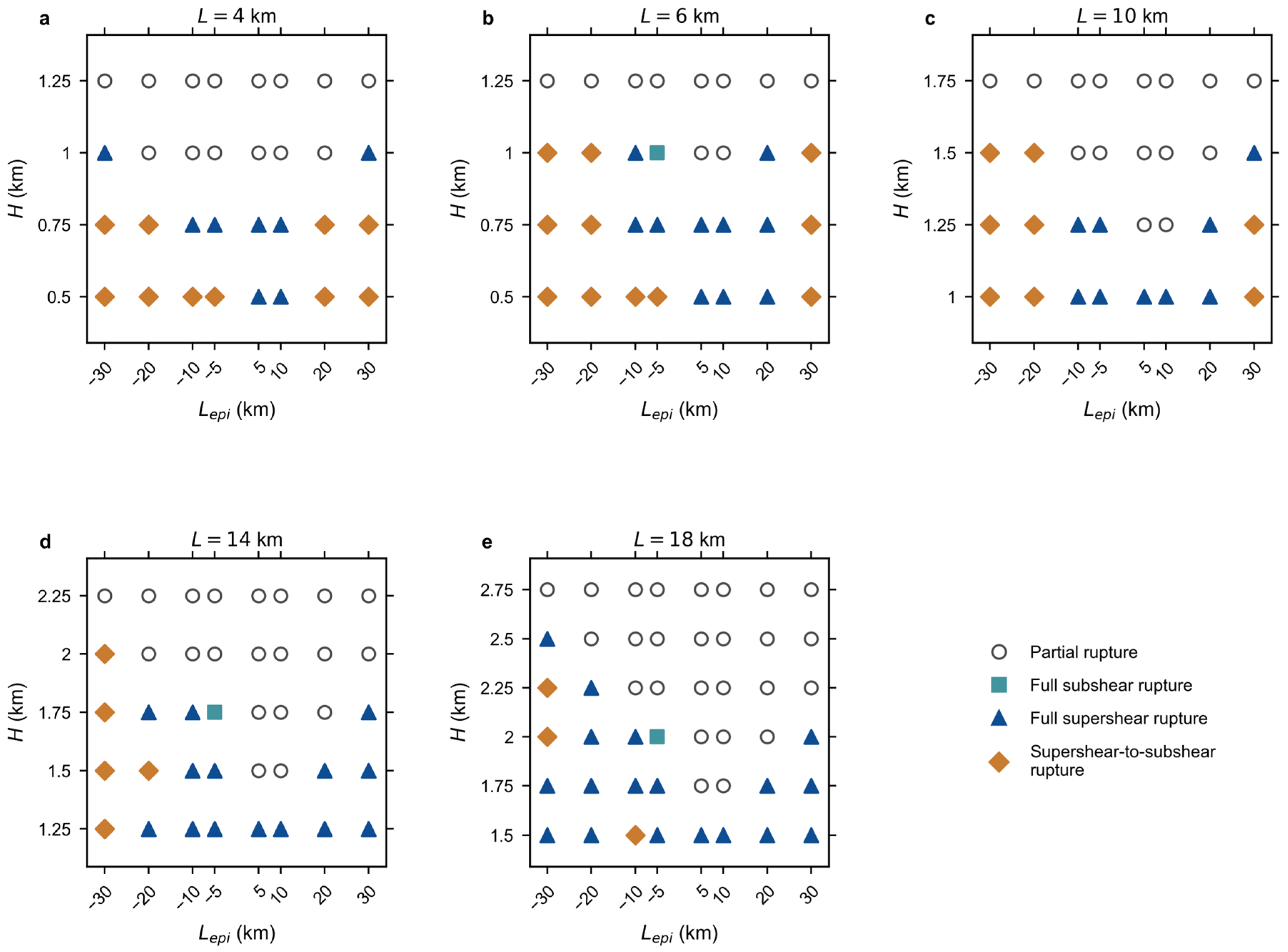
The full buried-fault survey contains four outcome classes (Figure 8). Compared with the surface-breaking models, partial rupture appears at a smaller for the same . Full subshear rupture occurs only in a small number of cases, whereas many successful cascading ruptures develop either sustained or transient supershear propagation on the far side of the undulation.
Figure 8.
Rupture outcomes for faults buried by 2 km. Open circles indicate partial rupture, cyan squares full subshear rupture, blue triangles sustained full supershear rupture, and orange diamonds rupture that transitions from supershear back to subshear speed. Positive Lepi denotes nucleation on the left side of the undulation, whereas negative Lepi denotes nucleation on the right side.
The regime boundaries depend jointly on , , and the sign and magnitude of . There is no single critical height that separates all partial and full ruptures, nor a single hypocentral distance that separates sustained and transient supershear behavior. Nevertheless, two robust tendencies emerge. First, increasing geometric severity promotes arrest. Second, an adequate pre-bend propagation distance is generally required for cascading, but excessive distance does not guarantee sustained supershear propagation. These tendencies demonstrate that rupture connectivity and rupture speed, although coupled, are distinct dynamical outcomes.
4. Discussion
4.1. A Smooth Undulation as a Directional Rupture Gate
The barrier–asperity pair implies that geometric segmentation is conditional rather than fixed. Because the relative favorability of the two flanks depends on stress orientation, slip sense, and rupture approach direction, the same undulation may transmit one rupture and arrest another.
This conditional behavior is consistent with bend and stepover studies that emphasize prestress and approach direction [2,3], and with paleoseismic evidence for repeated termination but occasional breach at Aksay [11]. The comparison remains conceptual because Aksay contains multiple strands, distributed transpression, and inherited stress that are absent from the present model.
4.2. Length, Height, Angle, and Curvature
The aspect ratio H/L is useful for describing nominal bend severity, but it cannot by itself collapse the regime boundaries because the simulations retain a fixed nucleation scale. A more complete nondimensional description would require H/L, together with quantities such as L/Rnuc, H/Rnuc, and Lepi/L, where Rnuc is the radius of the circular nucleation patch. Thus, two bends with the same H/L but different absolute dimensions span different numbers of nucleation radii and can produce different outcomes. We have not performed an independent scaling suite sufficient to identify a universal nondimensional collapse, so the present regime diagrams should be interpreted as conditional dimensional maps for the adopted stress, friction, nucleation, and numerical parameters.
The increase in allowable with demonstrates that amplitude alone is not a sufficient descriptor. For a given height, a broader undulation rotates the fault more gradually, moderating the local traction gradient and wave scattering; a shorter feature produces larger slope and curvature over a smaller distance. Conversely, comparing cases only by maximum bend angle may miss the finite width of the unfavorable zone and the distance over which the favorable flank can accelerate rupture.
The sampled position-independent transmission angles should not be interpreted as a universal critical angle. The one-sided angle captures the overall flank deflection but not the maximum local curvature, the width of the unfavorable zone, or the distance available for acceleration on the favorable flank. Double-bend studies likewise find coupled effects of geometry and stress [3], while rough-fault simulations show that multiple scales do not collapse onto a single angle [8]. A denser sampling of , together with direct measures of curvature and strength excess and systematic comparison with frictional length scales and rupture-front and traction evolution, is needed to identify the most useful nondimensional control parameter.
4.3. Hypocentral Position and Rupture-Front Maturity
The effect of hypocentral distance is best interpreted as rupture-front maturation: additional propagation on the planar segment allows the front to expand and accelerate before it reaches the undulation. This directly observed change in front development explains why some near-bend ruptures arrest and why distant nucleation can make a near-critical geometry transmissive.
Run-up distance does not, however, determine whether supershear persists after transmission. That outcome depends on the post-bend stress state and rupture-front evolution, so connectivity and sustained supershear remain separate thresholds; a rupture may cross the bend without remaining intersonic or exhibit only a localized supershear episode. We do not calculate an energy flux or a rupture-energy budget in this study; the mechanistic interpretation is therefore based on rupture-speed, slip-rate, and stress evolution rather than a direct energetic diagnostic.
4.4. Free-Surface and Geometric Routes to Supershear
The planar references isolate the free-surface contribution: under identical background strength, friction, elastic properties, and nucleation, only the surface-breaking planar fault becomes supershear (Figure 2; [28,29]). In the surface-breaking wavy models, the undulation therefore mainly determines whether the rupture remains connected long enough for this shallow feedback to operate.
By contrast, supershear in the buried wavy models cannot be attributed to the planar background state alone and is consistent with an additional contribution from non-planar geometry. The slip-rate, shear-stress, and normal-stress snapshots for the representative L = 6 km, H = 1 km, and Lepi = −10 km case show localized stress perturbations during bend crossing followed by a renewed high-slip-rate front on the far side (Supporting Figure S2). Their spatial and temporal correspondence provides direct simulation support for a dynamic contribution associated with the barrier–asperity pair.
Barrier-related models provide a plausible dynamic interpretation: deceleration or arrest of the primary front can radiate a stopping phase, concentrate stress ahead of the barrier, and initiate a daughter rupture on a favorably loaded receiver [4,5,6,7]. In the present geometry, the favorable flank can act as that receiver, while near-source pulses proposed by Page et al. [34] offer a possible observational diagnostic.
The supershear-to-subshear cases further indicate that the geometric perturbation is finite in duration: it may initiate an intersonic front without maintaining the dynamic-stress conditions needed to sustain it on the planar far-side segment. Comparable acceleration–deceleration behavior occurs in stepover and rough-fault models [6,8]. The new diagnostic snapshots document the coincident slip-rate and stress evolution, but quantitatively separating static traction changes, dynamic stress concentration, and individual reflected or scattered wave phases would require local traction time histories and wavefield decomposition.
4.5. Natural Structures and Earthquake Analogues
There are real active faults with broadly comparable geometry, but no example should be treated as an exact replica of the model. The Aksay restraining double bend is the closest double-bend structural analogue and has direct evidence for repeated barrier behavior and occasional breach [10,11]. The Parkfield–Cholame San Andreas Fault contains an approximately 50 km-long asymmetric warp that links rupture domains associated with recurrent Parkfield earthquakes and the 1857 Fort Tejon rupture [12]. Its inferred simplification with depth is particularly relevant: surface waviness may overestimate the geometric perturbation experienced by a deeper rupture. Corrugated fault surfaces, including the Costa Rica megathrust, demonstrate that wave-like geometry can persist at seismogenic depths [13], although dip-slip megathrust mechanics differ from the vertical strike-slip configuration studied here. Because the modeled amplitude is retained through the full 20 km down-dip fault width, the model also retains the associated fault rotation and traction contrast at depth. If a natural undulation decreases in amplitude downward, as inferred near Parkfield–Cholame, the deep barrier would be weaker, transmission would generally be easier, and the present model would tend to overestimate both deep rupture arrest and the magnitude of geometry-related dynamic perturbations. The 2 km-buried results therefore demonstrate that geometry can remain dynamically important without direct rupture–surface intersection, but they should be viewed as an upper-bound estimate for faults that simplify with depth.
Several recent earthquakes are stronger dynamical than geometrical analogues. The 2020 Caribbean event combined long unilateral strike-slip rupture, two supershear episodes, and changes in rupture behavior near geometric complexity on the Oriente transform [20]. The 2021 Maduo earthquake illustrates how geometry, prestress, and fracture-energy heterogeneity can jointly produce repeated supershear onset and cascading activation of neighboring branches [21]. The 2023 Kahramanmaraş sequence demonstrates supershear triggering and cascading through a fault network, with both heterogeneous prestress and geometric barriers implicated [22,23,24,25]. These cases support the model’s central premise—that geometry can regulate connectivity and rupture speed simultaneously—but contain branches, junctions, and heterogeneity beyond the present idealization.
4.6. Implications for Segmentation and Seismic Hazard
A chain of natural undulations could act as a sequence of directional gates. Passage through one feature determines the incident size, speed, and stress pulse delivered to the next, allowing small differences in nucleation location or direction to generate different final rupture extents. The results therefore suggest that geometric segmentation may be history dependent rather than purely structural, and they provide testable hypotheses for models that represent mapped segment boundaries.
The distinction between surface-breaking and buried geometry has direct implications for near-fault hazard. Sustained shallow supershear can generate a coherent Mach front and concentrated near-source shaking, whereas rupture arrest or a supershear-to-subshear transition changes the spatial distribution and frequency content of radiated motion [34]. Rupture directivity can additionally produce strong azimuthal variation in pulse amplitude, duration, and spectral demand [18,19,35,36,37,38]. Translating the present rupture-state maps into quantitative hazard estimates will therefore require explicit ground-motion simulations; the regime diagrams alone do not predict site-specific shaking.
4.7. Limitations and Outlook
The regime diagrams are conditional on one stress orientation, one slip-weakening parameter set, one nucleation size, a homogeneous elastic medium, a vertically invariant smooth geometry, and two upper-edge configurations. They describe trends within the sampled parameter space rather than universal phase boundaries for natural faults. The idealized model excludes material heterogeneity, inherited stress variations, branches, secondary faults, multiple undulations, and changes in fault geometry with depth. These simplifications isolate the coupled effects of waviness, rupture direction, nucleation distance, and surface proximity, but they limit direct transfer of the inferred thresholds to specific fault systems. In particular, no additional differential-stress states were tested, so the reported regime boundaries should not be interpreted as stress-independent. Likewise, retaining the full undulation amplitude over the 20 km down-dip width likely overestimates the deep barrier effect for natural faults whose geometry becomes smoother with depth.
Future work should examine how the directional barrier–asperity asymmetry changes with regional stress orientation and slip sense, and how the transition between surface-related and geometry-related rupture behavior varies with burial depth. Future studies should also test whether the barrier–asperity asymmetry and the resulting rupture-regime boundaries persist under a rate-and-state friction law, in which fault strength evolves with slip velocity and state rather than through a prescribed slip-weakening distance. Models containing multiple undulations, depth-varying fault surfaces, heterogeneous initial stresses, and secondary fault structures would extend the present framework toward the more complex natural fault systems discussed above.
5. Conclusions
Three-dimensional dynamic-rupture simulations show that a single wave-like irregularity can exert first-order control on rupture connectivity and rupture speed along a vertical strike-slip fault. The principal findings are the following:
- A uniform regional stress resolved onto the wavy fault creates an asymmetric barrier–asperity pair, making rupture transmission direction dependent.
- Increasing undulation height at fixed length promotes rupture arrest, whereas longer-wavelength undulations tolerate larger absolute heights. Neither height nor bend angle alone defines a universal transmission threshold.
- Hypocenters farther from the undulation generally favor cascading because the rupture has more distance to mature before reaching the barrier. However, connectivity and sustained supershear are separate, non-monotonic outcomes.
- The planar reference models show that a surface-breaking fault develops free-surface-induced supershear at (), whereas the otherwise equivalent planar fault buried by 2 km remains subshear. Burial also narrows the parameter range for cascading on the wavy fault.
- Buried wavy-fault models nevertheless develop supershear rupture at depth, including transient intersonic fronts that later decelerate to subshear speed, consistent with a geometry-induced contribution.
These regime boundaries remain conditional on the adopted stress orientation, friction law, nucleation procedure, homogeneous medium, and vertically invariant geometry, and should not be interpreted as universal thresholds for natural faults.
Together, the results indicate that fault shape, rupture direction, hypocentral position, and surface proximity must be treated as coupled controls. Even one smooth undulation can divide an otherwise uniform fault into distinct dynamic regimes. This framework provides a mechanical basis for testing how mapped fault waviness may influence rupture segmentation, barrier breach, and supershear occurrence.
Supplementary Materials
The following supporting information can be downloaded at: https://www.mdpi.com/article/10.3390/geosciences16090361/s1, Figure S1: Grid-convergence comparison; Figure S2: Dynamic rupture diagnostics.
Author Contributions
Conceptualization, J.X.; methodology, J.X.; software, J.X.; validation, J.X. and Y.X.; formal analysis, J.X.; investigation, J.X. and Y.X.; resources, Y.X.; data curation, J.X.; writing—original draft preparation, J.X.; writing—review and editing, J.X. and Y.X.; visualization, J.X. and Y.X.; project administration, J.X.; funding acquisition, J.X. and Y.X. All authors have read and agreed to the published version of the manuscript.
Funding
This research was funded by the National Key Research and Development Program of China, grant number 2023YFC3007302, and the National Natural Science Foundation of China, grant number 42174060.
Institutional Review Board Statement
Not applicable.
Informed Consent Statement
Not applicable.
Data Availability Statement
No external datasets were used in this study. The simulation data supporting the findings of this study are available from the corresponding author upon reasonable request. The CGFDM source code used for the simulations is publicly available at https://github.com/Zijia-Wang/CGFDM (accessed on 5 August 2026).
Conflicts of Interest
The authors declare no conflicts of interest.
References
- Harris, R.A.; Day, S.M. Dynamics of fault interaction: Parallel strike-slip faults. J. Geophys. Res. Solid Earth 1993, 98, 4461–4472. [Google Scholar] [CrossRef] [Scilit]
- Kame, N.; Rice, J.R.; Dmowska, R. Effects of prestress state and rupture velocity on dynamic fault branching. J. Geophys. Res. Solid Earth 2003, 108, 2265. [Google Scholar] [CrossRef] [Scilit]
- Lozos, J.C.; Oglesby, D.D.; Duan, B.; Wesnousky, S.G. The effects of double fault bends on rupture propagation: A geometrical parameter study. Bull. Seismol. Soc. Am. 2011, 101, 385–398. [Google Scholar] [CrossRef] [Scilit]
- Dunham, E.M.; Favreau, P.; Carlson, J.M. A supershear transition mechanism for cracks. Science 2003, 299, 1557–1559. [Google Scholar] [CrossRef] [Scilit] [PubMed]
- Weng, H.; Huang, J.; Yang, H. Barrier-induced supershear ruptures on a slip-weakening fault. Geophys. Res. Lett. 2015, 42, 4824–4832. [Google Scholar] [CrossRef] [Scilit]
- Hu, F.; Xu, J.; Zhang, Z.; Chen, X. Supershear transition mechanism induced by step over geometry. J. Geophys. Res. Solid Earth 2016, 121, 8738–8749. [Google Scholar] [CrossRef] [Scilit]
- Xu, J.; Zhang, Z.; Chen, X. The effects of barriers on supershear rupture. Geophys. Res. Lett. 2016, 43, 7478–7485. [Google Scholar] [CrossRef] [Scilit]
- Bruhat, L.; Fang, Z.; Dunham, E.M. Rupture complexity and the supershear transition on rough faults. J. Geophys. Res. Solid Earth 2016, 121, 210–224. [Google Scholar] [CrossRef] [Scilit]
- Yao, S.; Yang, H. Rupture phases reveal geometry-related rupture propagation in a natural earthquake. Sci. Adv. 2025, 11, eadq0154. [Google Scholar] [CrossRef] [Scilit] [PubMed]
- Xiao, Q.; Yu, G.; Liu-Zeng, J.; Oskin, M.E.; Shao, G. Structure and geometry of the Aksay restraining double bend along the Altyn Tagh Fault, northern Tibet, imaged using magnetotelluric method. Geophys. Res. Lett. 2017, 44, 4090–4097. [Google Scholar] [CrossRef] [Scilit]
- Shao, Y.; Liu-Zeng, J.; Oskin, M.E.; Elliott, A.J.; Wang, P.; Zhang, J.; Yuan, Z.; Li, Z. Paleoseismic investigation of the Aksay restraining double bend, Altyn Tagh Fault, and its implication for barrier-breaching ruptures. J. Geophys. Res. Solid Earth 2018, 123, 4307–4330. [Google Scholar] [CrossRef] [Scilit]
- Simpson, R.W.; Barall, M.; Langbein, J.; Murray, J.R.; Rymer, M.J. San Andreas Fault geometry in the Parkfield, California, region. Bull. Seismol. Soc. Am. 2006, 96, S28–S37. [Google Scholar] [CrossRef] [Scilit]
- Edwards, J.H.; Kluesner, J.W.; Silver, E.A.; Brodsky, E.E.; Brothers, D.S.; Bangs, N.L.; Kirkpatrick, J.D.; Wood, R.; Okamoto, K. Corrugated megathrust revealed offshore from Costa Rica. Nat. Geosci. 2018, 11, 197–202. [Google Scholar] [CrossRef] [Scilit]
- Resor, P.G.; Meer, V.E. Slip heterogeneity on a corrugated fault. Earth Planet. Sci. Lett. 2009, 288, 483–491. [Google Scholar] [CrossRef] [Scilit]
- Andrews, D.J. Rupture velocity of plane strain shear cracks. J. Geophys. Res. 1976, 81, 5679–5687. [Google Scholar] [CrossRef] [Scilit]
- Dunham, E.M. Conditions governing the occurrence of supershear ruptures under slip-weakening friction. J. Geophys. Res. Solid Earth 2007, 112, B07302. [Google Scholar] [CrossRef] [Scilit]
- Liu, Y.; Lapusta, N. Transition of mode II cracks from sub-Rayleigh to intersonic speeds in the presence of favorable heterogeneity. J. Mech. Phys. Solids 2008, 56, 25–50. [Google Scholar] [CrossRef] [Scilit]
- Parker, G.A.; Baltay, A.S.; Hirakawa, E.T. An empirical Green’s function approach for isolating directivity effects in earthquake ground-motion amplitudes. Bull. Seismol. Soc. Am. 2025, 115, 2336–2354. [Google Scholar] [CrossRef] [Scilit]
- Colavitti, L.; Lanzano, G.; Sgobba, S.; Pacor, F. Empirical modeling of source directivity effects into a ground-motion model for Central Italy. Bull. Seismol. Soc. Am. 2026, 116, 1081–1102. [Google Scholar] [CrossRef] [Scilit]
- Tadapansawut, T.; Okuwaki, R.; Yagi, Y.; Yamashita, S. Rupture process of the 2020 Caribbean earthquake along the Oriente transform fault, involving supershear rupture and geometric complexity of fault. Geophys. Res. Lett. 2021, 48, e2020GL090899. [Google Scholar] [CrossRef] [Scilit]
- Hayek, J.N.; Marchandon, M.; Li, D.; Pousse-Beltran, L.; Hollingsworth, J.; Li, T.; Gabriel, A. Non-typical supershear rupture: Fault heterogeneity and segmentation govern unilateral supershear and cascading multi-fault rupture in the 2021 Mw 7.4 Maduo earthquake. Geophys. Res. Lett. 2024, 51, e2024GL110128. [Google Scholar] [CrossRef] [Scilit]
- Abdelmeguid, M.; Zhao, C.; Yalcinkaya, E.; Gazetas, G.; Elbanna, A.; Rosakis, A. Dynamics of episodic supershear in the 2023 M7.8 Kahramanmaraş/Pazarcik earthquake, revealed by near-field records and computational modeling. Commun. Earth Environ. 2023, 4, 456. [Google Scholar] [CrossRef] [Scilit]
- Ren, C.; Wang, Z.; Taymaz, T.; Hu, N.; Luo, H.; Zhao, Z.; Yue, H.; Song, X.; Shen, Z.; Xu, H.; et al. Supershear triggering and cascading fault ruptures of the 2023 Kahramanmaraş, Türkiye, earthquake doublet. Science 2024, 383, 305–311. [Google Scholar] [CrossRef] [Scilit] [PubMed]
- Chen, K.; Wei, G.; Milliner, C.; Zilio, L.D.; Liang, C.; Avouac, J.-P. Super-shear ruptures steered by pre-stress heterogeneities during the 2023 Kahramanmaraş earthquake doublet. Nat. Commun. 2024, 15, 7004. [Google Scholar] [CrossRef] [Scilit] [PubMed]
- Zhou, J.; Xu, Y.; Zhang, Y.; Feng, W.; Taymaz, T.; Chen, Y.-T.; Xu, C.; Xu, B.; Wang, R.; Shi, F.; et al. Geometric barriers impacted rupture processes and stress releases of the 2023 Kahramanmaraş, Türkiye, earthquake doublet. Commun. Earth Environ. 2025, 6, 56. [Google Scholar] [CrossRef] [Scilit]
- Zheng, A.; Bai, C.; Xu, W.; Zhang, W.; Chen, X. Mixed subshear and supershear rupture kinematics of the 2023 Kahramanmaraş, Türkiye earthquake doublet modulated by complex fault geometry. Bull. Seismol. Soc. Am. 2026. [Google Scholar] [CrossRef] [Scilit]
- Yücel, B.; Hernández-Aguirre, V.M.; Odabasi, O.; Kohrangi, M.; Vanini, M.; Smerzini, C.; Paolucci, R.; Bazzurro, P. Investigating the 2023 Mw 7.8 Kahramanmaraş earthquake ground motion through 3D physics-based numerical simulations. Bull. Seismol. Soc. Am. 2026. [Google Scholar] [CrossRef] [Scilit]
- Kaneko, Y.; Lapusta, N. Supershear transition due to a free surface in 3-D simulations of spontaneous dynamic rupture on vertical strike-slip faults. Tectonophysics 2010, 493, 272–284. [Google Scholar] [CrossRef] [Scilit]
- Xu, J.; Zhang, H.; Chen, X. Rupture phase diagrams for a planar fault in 3-D full-space and half-space. Geophys. J. Int. 2015, 202, 2194–2206. [Google Scholar] [CrossRef] [Scilit]
- Zhang, Z.; Zhang, W.; Chen, X. Three-dimensional curved grid finite-difference modelling for non-planar rupture dynamics. Geophys. J. Int. 2014, 199, 860–879. [Google Scholar] [CrossRef] [Scilit]
- Madariaga, R.; Olsen, K.B. Criticality of rupture dynamics in 3-D. Pure Appl. Geophys. 2000, 157, 1981–2001. [Google Scholar] [CrossRef] [Scilit]
- Hu, F.; Zhang, Z.; Chen, X. Investigation of earthquake jump distance for strike-slip step overs based on 3-D dynamic rupture simulations in an elastic half-space. J. Geophys. Res. Solid Earth 2016, 121, 994–1006. [Google Scholar] [CrossRef] [Scilit]
- Xu, J.; Zhang, Z.; Chen, X. The effects of sediments on supershear rupture. Tectonophysics 2021, 805, 228777. [Google Scholar] [CrossRef] [Scilit]
- Page, M.T.; Dunham, E.M.; Carlson, J.M. Distinguishing barriers and asperities in near-source ground motion. J. Geophys. Res. Solid Earth 2005, 110, B11302. [Google Scholar] [CrossRef] [Scilit]
- Spudich, P.; Rowshandel, B.; Shahi, S.K.; Baker, J.W.; Chiou, B.S.-J. Comparison of NGA-West2 directivity models. Earthq. Spectra 2014, 30, 1199–1221. [Google Scholar] [CrossRef] [Scilit]
- Withers, K.B.; Moschetti, M.P.; Powers, P.M.; Petersen, M.D.; Graves, R.; Aagaard, B.T.; Baltay, A.S.; Luco, N.; Wirth, E.A.; Rezaeian, S.; et al. Integration of rupture directivity models for the US National Seismic Hazard Model. Earthq. Spectra 2024, 40, 1066–1098. [Google Scholar] [CrossRef] [Scilit]
- Bayless, J.; Abrahamson, N.A.; Somerville, P.G. A rupture directivity adjustment model and its application in seismic hazard. Earthq. Spectra 2025, 41, 753–781. [Google Scholar] [CrossRef] [Scilit]
- Abdelmeguid, M.; Lavrentiadis, G.; Rosakis, A.J.; Asimaki, D. Ground-motion characteristics of idealized supershear ruptures: Do they matter for engineering applications? Bull. Seismol. Soc. Am. 2026. [Google Scholar] [CrossRef] [Scilit]
Disclaimer/Publisher’s Note: The statements, opinions and data contained in all publications are solely those of the individual author(s) and contributor(s) and not of MDPI and/or the editor(s). MDPI and/or the editor(s) disclaim responsibility for any injury to people or property resulting from any ideas, methods, instructions or products referred to in the content. |
© 2026 by the authors. Licensee MDPI, Basel, Switzerland. This article is an open access article distributed under the terms and conditions of the Creative Commons Attribution (CC BY) license.