


Abstract
Large lunar impacts generate substantial volumes of shock melt that can pond within basin interiors. Because mare basalts only partly cover Orientale, the basin preserves extensive exposures of the Maunder Formation and provides an unusual record of basin-scale impact-melt emplacement and modification. We use KAGUYA Terrain Camera images and SLDEM2015 topography, together with slope and hillshade products, to characterize four morphologic elements of the smooth facies. The inner-depression bounding scarp separates the fissured and smooth facies and contains two back-tilted bench-like steps—relatively planar intermediate surfaces bounded by slope breaks—consistent with stepped normal-fault displacement. Hummocky terrain comprises mounds, short ridges, and fissured troughs with 100–200 m of typical relief and is consistent with disruption of a quenched surface crust containing breccia clasts. Floor massifs rise from flat-topped plateaus bounded by 300–500 m scarps; we interpret them as candidate crustal megablocks that locally promoted freezing of the surrounding melt. Marginal transitional terrain is fractured and tilted inward across a broad, low-gradient zone, recording differential subsidence near the facies boundary. Together, these landforms are consistent with progressive top-down cooling, crustal thickening, and differential subsidence of a centrally thickened melt body. However, basin-scale relief also records mantle uplift, ring-related faulting, isostatic adjustment, and later magmatic modification. The previously inferred 20–25 km maximum melt-sheet thickness should therefore be regarded as a model-dependent end-member upper bound rather than a unique solution.
1. Introduction
Hypervelocity impacts produce impact melt that deposits occur on the floors, walls, and rims of lunar impact craters and basins [1,2], and there is a range of field and experimental evidence that proportionally the melt fraction generally increases with crater size [3,4], with the amount of melt produced ranging from millimeter-sized droplets to impressive seas of melt [5]. During basin-forming impacts, much of this melt collects in the basin interior, while smaller fractions are entrained in ejecta or emplaced as flows and ponds beyond the central cavity [6,7], and appears to have remained at least semi-molten for a considerable time, as evidenced by lava-like channels that appear to have emplaced melt deposits in the center of the basin [8]. Numerical models predict central melt bodies tens of kilometers deep and hundreds of kilometers across [9,10,11,12]. Such bodies may cool through a rapidly quenched upper crust over a vigorously convecting interior. Their crystallization paths depend on melt composition, crystal size, clast abundance, and the efficiency of crystal settling [13,14,15].
Multiring basins are the large impact craters on the Moon, most of which formed early in lunar history and are older than ~3.8 Ga [16], and their great age means that the original surface landforms of their deposits have been largely destroyed, subdued, or erased by impact erosion and burial by subsequent units. Recent geological mapping of the Orientale [17], Imbrium [18], and Crisium [19] impact basins has revealed impact melt deposits formed during these basin-forming events. However, the nature of impact melt formation and evolution in lunar basins is uncertain because of post-basin flooding and modification by mare volcanic deposits, and obscuration of the basin interior [20], where the majority of melt resides [2,16,21,22]. The Orientale basin, the youngest multiring basin on the Moon, lacks extensive mare flooding and best preserves the original characteristics of an impact basin; it has long been regarded as a prototype basin whose study can shed light on the processes and histories of older, more degraded basins [16,21,23,24], and crater counts on its ejecta yield an absolute model age of about 3.80 Ga [25]. Assuming that most lunar basins originally resembled the unflooded Orientale basin, understanding the Orientale melt sheet is key to recognizing impact melt deposits in older, more degraded, and partly flooded basins. Modern mapping shows that Orientale melt-rich ejecta were emplaced after ballistic ejecta and were strongly guided by pre-existing topography [6]. GRAIL analyses further show that the preserved surface relief is superposed on a complex subsurface structure that includes mantle uplift, crustal thinning, and ring-related faults and density anomalies [26,27,28]. These results make Orientale an important natural laboratory, but they also require surface morphology attributed to melt cooling to be distinguished from deformation inherited from basin collapse, isostatic adjustment, and later magmatism.
The Maunder Formation has commonly been divided into an outer corrugated or fissured facies and an inner smooth plains facies [22,29]. Here we map and measure four recurring elements of the smooth facies: the inner-depression bounding scarp, hummocky floor terrain, floor massifs, and marginal transitional deformed terrain. We separate morphologic observations from genetic interpretation, evaluate how the features fit a cooling-and-subsidence sequence, and identify where the interpretation remains non-unique. The resulting framework provides testable morphologic criteria for recognizing partly buried melt sheets in other lunar basins.
2. Data and Methods
In this study, regional image mosaics derived from the KAGUYA (SELENE) Terrain Camera (TC) stereo observations, with a spatial sampling of 4096 pixels per degree (corresponding to approximately 7.4 m/pixel), were employed to delineate and characterize the smooth facies of the Maunder Formation [30]. All image products were imported into a geographic information system (GIS) environment and co-registered to a common lunar coordinate framework to ensure consistent spatial referencing across datasets.
Topographic information was obtained from the SLDEM2015 dataset, which integrates Lunar Orbiter Laser Altimeter (LOLA) measurements with KAGUYA TC stereo-derived topography to produce a seamless global elevation model [31]. This cylindrical-projection product is gridded at 512 pixels per degree (~60 m/pixel at the equator) with a reported vertical accuracy of approximately 3–4 m.
The SLDEM2015 dataset was utilized to extract elevation profiles across representative geomorphic features, compute relief metrics, and generate derivative terrain products—including slope maps, analytical hillshade rasters, and three-dimensional perspective visualizations—to facilitate morphometric interpretation and to constrain the stratigraphic relationships of the mapped smooth facies units. All elevations reported here are the native SLDEM2015 elevations in the dataset reference frame; no additional constant elevation offset was applied to the profiles. Slope values were calculated from the DEM-derived surface. The profile panels retain labeled horizontal-distance and elevation axes; any apparent vertical emphasis is a consequence of the plotted panel aspect ratio rather than a separate topographic transformation. Accordingly, the profiles are used to compare relative morphology, and the numerical axes—not visual steepness—define the measured relief.
3. Maunder Formation: Impact Melt Sheet
The Maunder Formation occupies much of the Orientale basin interior beneath and around central Mare Orientale. It consists of smooth to undulating plains that grade outward into fissured and corrugated terrain draped across basin-interior topography [17,21,32]. The outer corrugated or fractured facies cover the Inner Rook plateau, from which peaks of the Inner Rook ring protrude. The inner plains facies are smooth, occupy the inner depression and are locally exposed through kilometer-scale gaps [22]. Large fractures, polygonal cracks, and inward-facing marginal scarps characterize the smooth facies. Most workers interpret the corrugated facies as clast-rich impact melt or a melt–ejecta mixture and the smooth facies as relatively clast-poor impact melt [17,21,33]. Remote-sensing data indicate that exposed surfaces are dominated by anorthositic crustal material and show no unambiguous surface exposure of mafic mantle material [17,34,35]. The crustal thickness below the center of the Orientale basin is estimated to be ~10 km [36,37]. LOLA data reveal the altimetry of the basin in detail and show that the inner depression lies at an average elevation of about 2 km below the corrugated facies that occupies the Inner Rook plateau [17]. This surface compositional result does not exclude deep mantle uplift beneath the basin, which is independently supported by gravity data [27,28].
Published maps broadly agree on the distribution of the basin-interior units but use different names and genetic interpretations [7,17,21,23,24,32]. Table 1 compares those classifications with the terminology adopted here.
Table 1.
Comparison of previously mapped interior units of the Orientale basin with the facies terminology used in this study.
LOLA topography resolves two first-order physiographic provinces inside the Outer Rook ring: the Inner Rook plateau and the lower inner depression, separated by an abrupt inward-facing margin [38,39]. The relief across this boundary is a composite signal. Plausible contributions include cooling and contraction of the impact melt, thermal equilibration of impact-heated substrate, uplift and subsequent relaxation of deep isotherms, crustal thinning, and displacement on ring-related structures [26,28,40].
Published estimates of Maunder Formation thickness span a wide range. Thermal and topographic models have yielded approximately 15 km near the basin center, whereas geologic reconstructions favor an average thickness of about 6 km or less with local thickening to 8–9 km [17,34]. Following Wilson and Head (2011) [38], in the end-member scaling used here, the initial sheet thickness H is the relief assigned to cooling divided by the effective vertical contraction strain of the cooling column, H = dz/e. With dz = 2 km and H = 20–25 km, the implied effective strain is e = dz/H, i.e., about 8–10%. The bound therefore scales linearly with both terms. (i) Partition of the relief: if only a fraction f of the 2 km is genuinely cooling-related, the remainder being produced by mantle uplift, crustal thinning, ring-related faulting, and isostatic adjustment, the bound becomes f x dz/e, so f = 0.5 and f = 0.25 reduce 20–25 km to approximately 10–12.5 km and 5–6 km, which brackets the geologic estimates of about 6 km [17]. (ii) Contraction coefficient and locking temperature: a larger thermal contraction coefficient, or a larger temperature interval between emplacement and the temperature at which the sheet becomes mechanically locked, increases e and lowers H proportionally. (iii) Initial temperature: a hotter post-impact sheet increases that temperature interval and hence the subsidence per unit thickness, so less thickness is needed to produce 2 km of relief. (iv) Porosity and substrate response: high porosity or a soft, thermally relaxing substrate absorbs part of the contraction and reduces surface subsidence for a given H, whereas basal thermal relaxation of impact-heated substrate adds displacement that is not proportional to sheet thickness at all. Because neither e nor f can be resolved from the present topographic data alone, we quote 20–25 km only as the f = 1 end-member upper bound and regard approximately 6–15 km as the range compatible with published geologic and thermal models; the coupled modeling recommended below is required to fix both terms.
4. Smooth Facies of the Maunder Formation
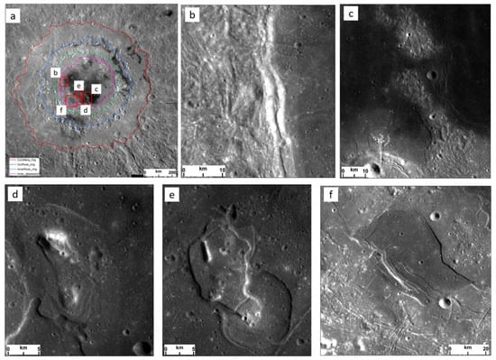
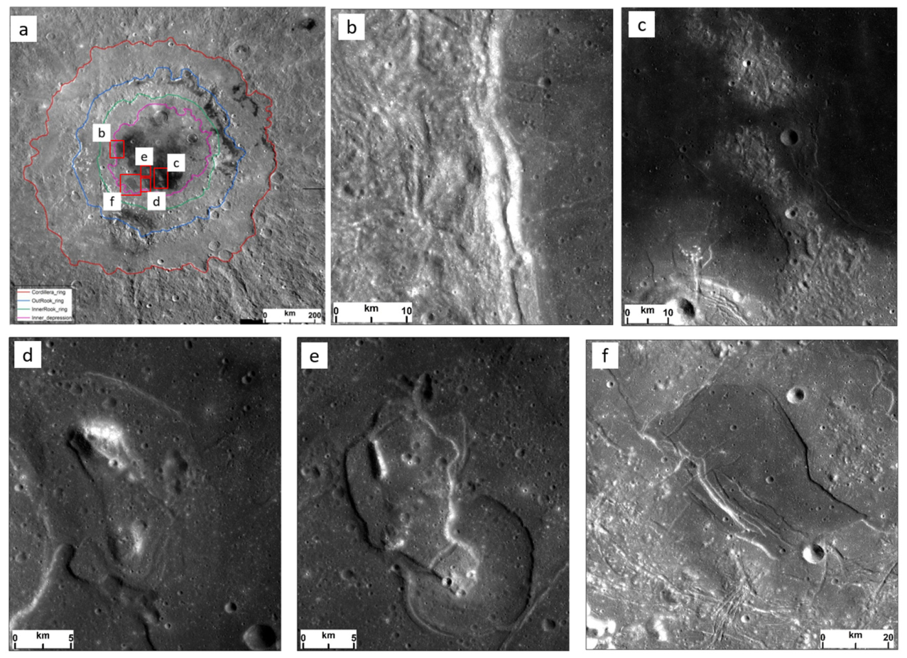
Within the inner depression, we specifically describe four elements of the smooth facies of the Maunder Formation (Figure 1) and interpret the surface morphology, morphometry, stratigraphy, and the sequence of major events in their evolution.
Figure 1.
Regional context and four elements of the smooth facies of the Maunder Formation, which occupies the basin interior within the Inner Rook ring (shaded area in panel (a)): (a) Orientale basin showing the extent of the Maunder Formation; (b) inner ring bounding scarp; (c) hummocky floor topography; (d) and (e) floor massifs; and (f) marginal transitional deformed terrain. Panels (b–f) show the locations and representative examples of the features described in Section 4.1, Section 4.2, Section 4.3 and Section 4.4.
4.1. Inner Ring Bounding Scarp
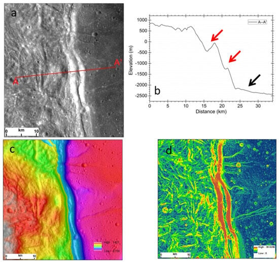
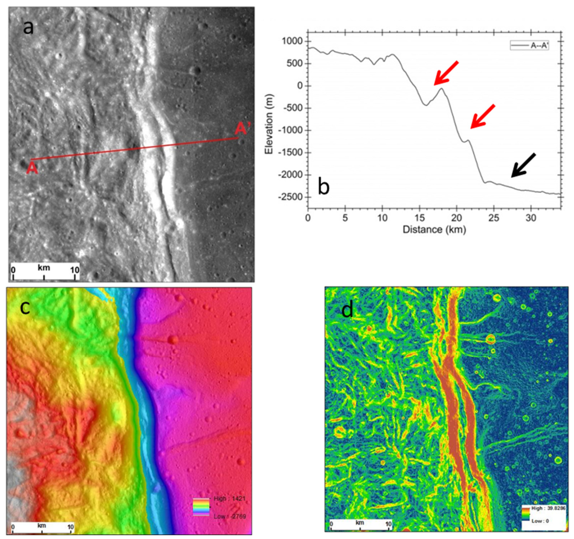
The inner ring bounding scarp is located at the edge of the inner ring depression along the western border. The top and base elevations of this scarp are ~720 m and ~−2200 m, dropping ~2.92 km over a lateral distance of only ~12 km (Figure 2), with slopes of less than 29°. There are two terraces located in the middle of this scarp (Figure 2b, red arrow): (1) the top one has an ~500 m elevation contrast and ~1500 m width with an ~18° outward slope, and (2) the second has an ~100 m elevation contrast and ~1000 m width with an ~5° outward slope. In addition, the base of this scarp (Figure 2b, black arrow) is a relatively flat terrain with an ~2° slope inward to the basin center. This scarp distinctly separates the fissured facies from the smooth facies of the basin interior; its two distinct back-tilted scarps suggest listric normal faults. Here, the term “bench” refers descriptively to a relatively low-gradient, step-like segment interrupting the otherwise steep scarp profile, bounded above and below by distinct slope breaks. It does not imply a separately mapped stratigraphic unit or a uniquely established fault geometry. The two bench-like segments identified in Figure 2b are approximately 1.5 km and 1.0 km wide, with elevation contrasts of about 500 m and 100 m, respectively.
Figure 2.
Topographic features of the inner ring bounding scarp: (a) KAGUYA TC image; (b) profile of SLDEM2015; (c) shaded SLDEM2015; (d) slope derived from the SLDEM2015 topographic product. Elevations in profile (b) are SLDEM2015 values without an added constant offset; axes are labeled in meters and kilometers.
We interpret the scarp as marking a pronounced lateral change in the thickness and mechanical behavior of the Maunder Formation. In a cooling model, the thinner fissured facies would solidify earlier than the thicker interior smooth facies, and differential subsidence could localize normal faulting at their boundary. The scarp relief constrains the combined effects of primary basin structure and post-emplacement subsidence; it does not, by itself, uniquely determine melt-sheet thickness [38].
4.2. Hummocky Floor Topography
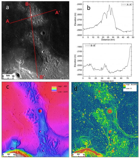
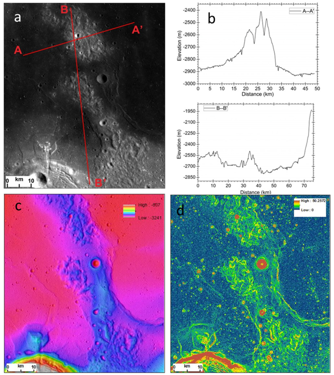
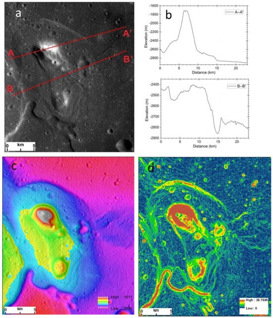
The hummocky terrain differs from the surrounding smooth basin floor and contains small mounds, short linear ridges, and fissured troughs (Figure 3). Typical relief is 100–200 m, locally reaching approximately 500 m, and hummock slopes range from about 5 to 30°. We tentatively interpret the terrain as a disrupted remnant of the quenched melt-sheet crust containing or draped over impact-breccia fragments. This interpretation is based on its position within the smooth facies and the association of positive-relief blocks with fractures; blocky fallback, primary floor roughness, and later tectonic modification remain possible contributors.
Figure 3.
Topographic features of the hummocky floor topography: (a) KAGUYA TC image; (b) profile of SLDEM2015; (c) shaded SLDEM2015; (d) slope derived from the SLDEM2015 topographic product. Elevations in profile (b) are SLDEM2015 values without an added constant offset; axes are labeled in meters and kilometers.
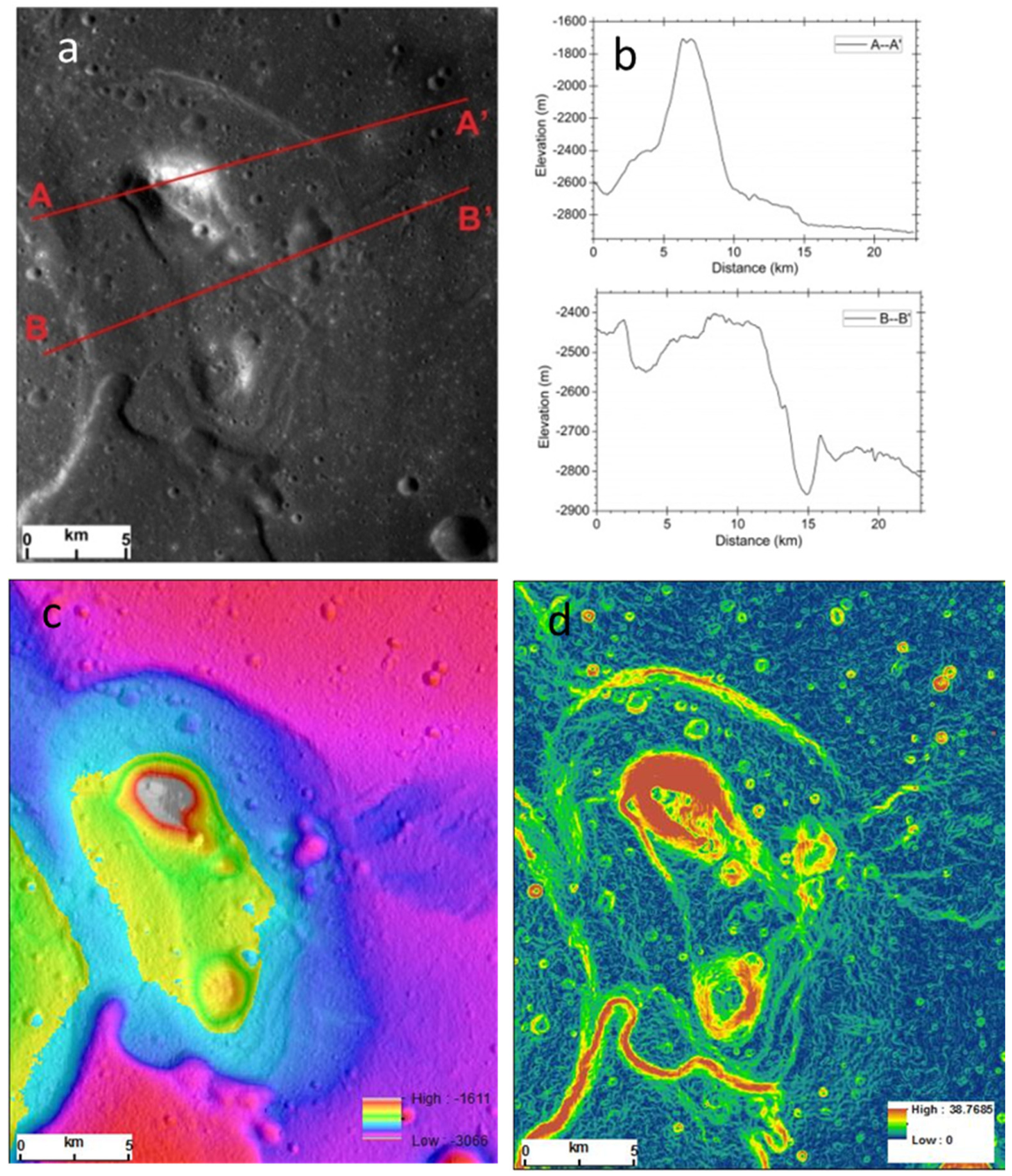
4.3. Floor Massifs
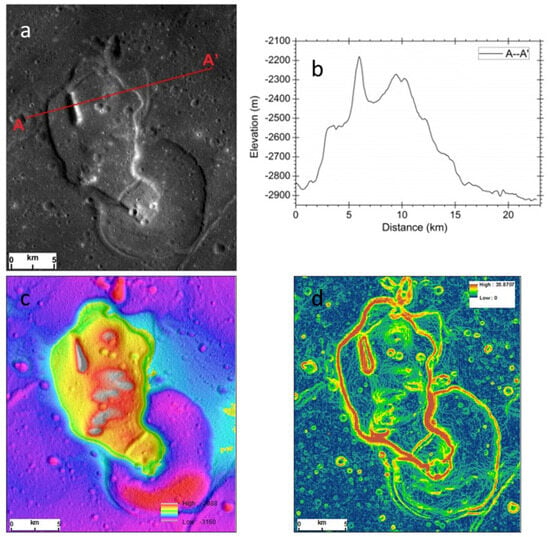
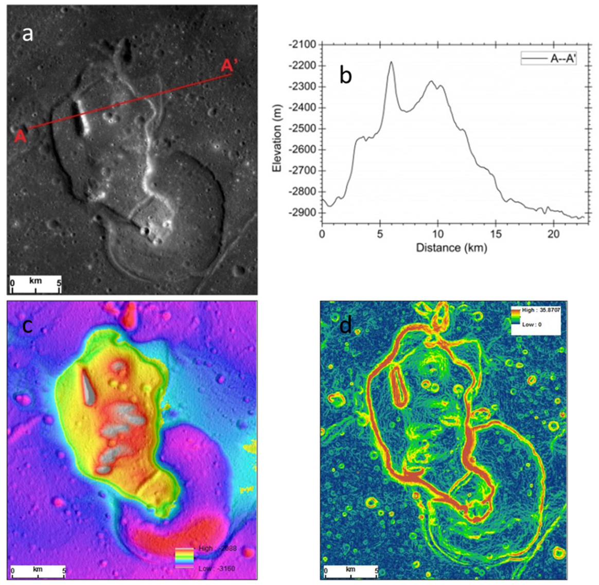
The floor massifs comprise central mountains that rise several hundred meters above irregular, comparatively flat plateaus (Figure 4 and Figure 5). The plateaus are approximately 10–20 km wide and are bounded by 10–30° scarps that rise 300–500 m above the surrounding plains. We interpret these features as candidate “rockbergs”: kilometer-scale crustal megablocks incorporated into the melt sea. In this model, a relatively cool block promoted local crystallization of the surrounding melt, forming a mechanically coherent plateau. Continued solidification and subsidence of the adjacent, hotter melt then fractured the plateau margins. The morphologic association is consistent with this mechanism, although block buoyancy and the thermal contrast require quantitative testing.
Figure 4.
Topographic features of a floor massif: (a) KAGUYA TC image; (b) profile of SLDEM2015; (c) shaded SLDEM2015; (d) slope derived from the SLDEM2015 topographic product. Elevations in profile (b) are SLDEM2015 values without an added constant offset; axes are labeled in meters and kilometers.
Figure 5.
Topographic features of a floor massif: (a) KAGUYA TC image; (b) profile of SLDEM2015; (c) shaded SLDEM2015; (d) slope derived from the SLDEM2015 topographic product. Elevations in profile (b) are SLDEM2015 values without an added constant offset; axes are labeled in meters and kilometers.
However, a simple buoyancy analysis supports this interpretation: the density contrast between anorthositic crustal blocks (~2700 kg/m3) and the surrounding impact melt (~2800–3000 kg/m3, depending on composition and crystallinity) generates a buoyancy force that can support blocks of the observed dimensions (10–20 km wide plateaus with 300–500 m bounding scarps) against rapid gravitational settling, particularly given the high viscosity of partially crystallized melt at near-solidus temperatures. The thermal timescale for a cold megablock to promote local crystallization of the surrounding melt can be estimated using the thermal diffusion timescale t ~ L2/D, where L is the block size (~10 km) and D is the thermal diffusivity (~10−6 m2/s), yielding t ~ 105–106 years. This timescale is consistent with the Cassanelli and Head (2016) [13] framework, which predicts that vigorous convection can cool the melt to the liquidus rapidly (within ~10 kyr for the uppermost layers) while bringing the deeper system to a crystal-rich state on timescales of 105–106 years. The compatibility of these timescales supports the feasibility of the rockberg mechanism, wherein relatively cool crustal blocks promote localized crystallization of the surrounding melt, forming mechanically coherent plateaus. While a full Stokes-flow calculation is beyond the scope of this morphologic study, the order-of-magnitude buoyancy estimate and thermal timescale analysis are consistent with the preservation of kilometer-scale crustal fragments within the melt sheet.
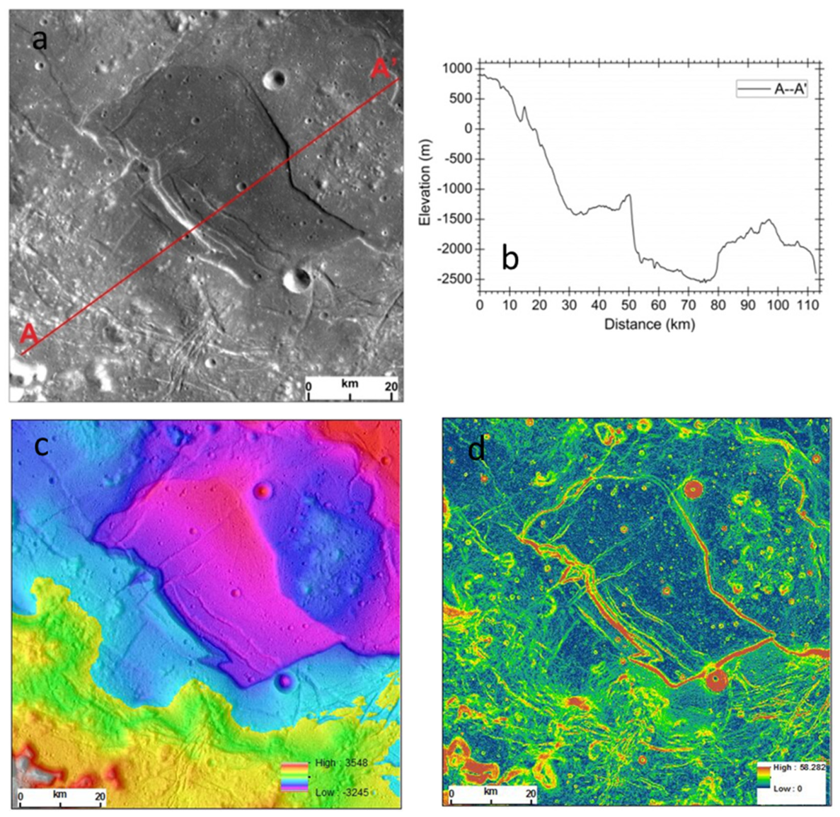
4.4. Marginal Transitional Deformed Terrain
This terrain occupies a broad transition between the steep scarp and smooth plains that contain floor massifs (Figure 6). Across a width of approximately 30 km, elevation decreases by about 2.3 km toward the basin interior; the average regional slope is approximately 2°. The transition therefore drapes across the underlying relief rather than forming a single discrete scarp. Its smooth surfaces are cut by abundant fractures, and individual blocks are separated by scarps with as much as approximately 700 m of relief. Several blocks tilt toward the basin center. We interpret this deformation as distributed faulting and tilting near the boundary between the fissured and smooth facies. In a cooling model, it records differential subsidence along the margin of a thickening thermal boundary layer; inherited basin structure or later fault reactivation may also have contributed.
Figure 6.
Topographic features of the marginal transitional deformed terrain: (a) KAGUYA TC image; (b) profile of SLDEM2015; (c) shaded SLDEM2015; (d) slope derived from the SLDEM2015 topographic product. Elevations in profile (b) are SLDEM2015 values without an added constant offset; axes are labeled in meters and kilometers.
The cooling model invoked here follows the framework of Wilson and Head (2011) [29], in which the subsidence of an impact melt sheet is driven by thermal contraction during top-down cooling. The key parameter linking subsidence to melt thickness is the effective vertical contraction strain e = dz/H, where dz is the net subsidence (relief) and H is the initial melt-sheet thickness. The contraction strain depends on the thermal contraction coefficient (typically (2–4) × 10–4 K−1 for silicate melts), the cooling interval (from emplacement temperature to the locking temperature at which the sheet becomes mechanically rigid), and the efficiency of crystal settling. Errors in the estimated thickness arise primarily from uncertainties in (i) the partitioning of the observed relief among cooling subsidence, mantle uplift, crustal thinning, ring-related faulting, and isostatic adjustment; (ii) the thermal contraction coefficient and locking temperature; and (iii) the initial temperature and porosity of the melt sheet. We discuss these dependencies and their implications for the inferred melt-sheet thickness in Section 3 and the Discussion.
5. Discussion
The mapped landforms can be arranged in a cooling-and-subsidence sequence following emplacement of the Orientale impact melt. A quenched surface crust would have formed rapidly above a convecting interior. Local disruption of that crust and incorporated breccia could produce the hummocky terrain. Large crustal megablocks may have locally accelerated cooling, creating coherent plateaus around the candidate floor massifs. As the interior continued to crystallize and contract, differential subsidence would fracture and tilt the marginal crust, producing distributed deformation across broad transitions and more localized faulting at the abrupt inner-depression scarp. Cassanelli and Head (2016) [13] predicted that vigorous convection could cool the melt to the liquidus rapidly and bring the system to a crystal-rich, solid-like state within roughly 10 kyr, while limiting the settling of crystals smaller than about 1.5 mm. That framework is compatible with a rapidly formed surface lid above a longer-lived, convecting interior.
The cooling model framework underlying this interpretation assumes that the Orientale impact melt sheet cooled from the top down, with a rapidly quenched surface crust forming above a vigorously convecting interior [13]. As the melt cooled and crystallized, thermal contraction produced vertical subsidence proportional to the integrated temperature drop and the thermal contraction coefficient. The rate of cooling was controlled by the efficiency of convection in the interior, the thermal conductivity of the growing crystalline lid, and the boundary conditions at the surface and base of the sheet. The model predicts that thicker portions of the melt sheet would take longer to fully crystallize, leading to differential subsidence between thick and thin regions, which is consistent with the morphologic patterns observed in the Maunder Formation smooth facies.
The morphology is compatible with a centrally thickened melt body, but the measured relief is not a unique cooling signal. GRAIL data resolve crust-penetrating structures at the major rings and a basin-centered density anomaly consistent with deep uplift and subsequent thermal and isostatic adjustment [26,27,28]. These processes can contribute to the elevation difference between the Inner Rook plateau and the inner depression. Accordingly, the approximately 2 km regional relief should be treated as a maximum end-member cooling-subsidence signal. The 20–25 km thickness derived when all of that relief is assigned to cooling is an upper bound; estimates of approximately 6–15 km remain viable within published geologic and thermal models.
Surface mineralogy provides an additional constraint but does not resolve the subsurface structure. The anorthositic character of exposed Maunder Formation surfaces indicates a strong crustal component, potentially including fallback breccia or a clast-rich upper layer [17,34]. It does not rule out mantle uplift at depth. Likewise, the present-day fractures may not all date from melt-sheet solidification: mapping of grabens and young boulder falls indicates that some Orientale structures experienced much later tectonic or seismic modification [41]. The cooling interpretation is therefore strongest where morphology, facies contacts, and cross-cutting relations jointly indicate deformation of the Maunder surface and weaker where topography alone supplies the evidence.
6. Conclusions
In this study, we documented and interpreted the four elements of the smooth facies of the Maunder Formation; the principal conclusions are summarized below:
(1) The inner ring bounding scarp separates the fissured facies from the smooth facies of the basin interior. Its stepped, back-tilted profile is consistent with normal faulting and may reflect differential cooling-related subsidence, superposed on primary basin structure; cooling is not uniquely established as its sole cause.
(2) The hummocky floor topography is composed of small mounds and hummocks, short linear ridges, and fissured troughs and probably represents the remnants of a quenched crust that contained floating elements of impact breccia fragments.
(3) The floor massifs consist of central mountains rising hundreds of meters above a relatively flat, irregularly shaped plateau, because kilometer-scale excavated crustal fragments float in the impact melt sea, cool their surroundings, and then fracture at the edge of the cooled plateau as the adjacent hotter melt continues to solidify and subside; they are interpreted as “rockbergs”.
(4) The marginal transitional deformed terrain occupies the transition between the steep scarp and smooth plains with floor massifs. Its fractures and inward-tilted blocks are consistent with distributed differential subsidence near the boundary between the fissured and smooth facies, although inherited basin structures and later fault reactivation remain viable contributors.
These observations and stratigraphic relationships support an impact-melt origin for the Maunder Formation and provide morphologic and first-order quantitative constraints on the possible cooling and subsidence history of the Orientale melt sheet. The thermal and rockberg interpretations remain testable hypotheses that require coupled thermal, mechanical, and gravity constraints.
Author Contributions
Conceptualization, methodology, investigation, writing, and funding acquisition, J.J.; data curation and visualization, W.Z. All authors have read and agreed to the published version of the manuscript.
Funding
This study was supported partly by the National Natural Science Foundation of China (No. 42462026).
Data Availability Statement
The original contributions presented in the study are included in the article; further inquiries can be directed to the corresponding author.
Acknowledgments
We are grateful to the teams involved in providing the data used in this study. The SLDEM2015 data are archived at the PDS Geosciences Node (http://imbrium.mit.edu/DATA/SLDEM2015 accessed on 6 July 2026), and the KAGUYA Terrain Camera images were obtained from the JAXA SELENE data archive (http://darts.isas.jaxa.jp/planet/pdap/selene/index.html.en accessed on 6 July 2026).
Conflicts of Interest
The authors declare no conflicts of interest.
References
- Melosh, H.J. Impact Cratering: A Geologic Process; Oxford University Press: New York, NY, USA, 1989; 245p. [Google Scholar]
- Spudis, P.D. The Geology of Multi-Ring Impact Basins: The Moon and Other Planets; Cambridge University Press: New York, NY, USA, 1993. [Google Scholar]
- Grieve, R.A.F.; Cintala, M.J. Planetary differences in impact melting. Adv. Space Res. 1997, 20, 1551–1560. [Google Scholar] [CrossRef] [Scilit]
- Cintala, M.J.; Grieve, R.A.F. Scaling impact melting and crater dimensions: Implications for the lunar cratering record. Meteorit. Planet. Sci. 1998, 33, 889–912. [Google Scholar] [CrossRef] [Scilit]
- Norman, M.D.; Taylor, L.A.; Shih, C.-Y.; Nyquist, L.E. Crystal accumulation in a 4.2 Ga lunar impact melt. Geochim. Cosmochim. Acta 2016, 172, 410–429. [Google Scholar] [CrossRef] [Scilit]
- Morse, Z.R.; Osinski, G.R.; Tornabene, L.L. New morphological mapping and interpretation of ejecta deposits from Orientale Basin on the Moon. Icarus 2018, 299, 253–271. [Google Scholar] [CrossRef] [Scilit]
- Spudis, P.D.; Hawke, B.R.; Lucey, P. Composition of Orientale basin deposits and implications for the lunar basin-forming process. J. Geophys. Res. 1984, 89, C197–C210. [Google Scholar] [CrossRef] [Scilit]
- Greeley, R. Modes of emplacement of basalt terrains and an analysis of mare volcanism in the Orientale Basin. Proc. Lunar Sci. Conf. 1976, 7, 2747–2759. [Google Scholar]
- Ivanov, B.A. Numerical modeling of the largest terrestrial meteorite craters. Sol. Syst. Res. 2005, 39, 381–409. [Google Scholar] [CrossRef] [Scilit]
- Johnson, B.C.; Blair, D.M.; Collins, G.S.; Melosh, H.J.; Freed, A.M.; Taylor, G.J.; Head, J.W.; Wieczorek, M.A.; Andrews-Hanna, J.C.; Nimmo, F.; et al. Formation of the Orientale lunar multiring basin. Science 2016, 354, 441–444. [Google Scholar] [CrossRef] [Scilit] [PubMed]
- Melosh, H.J.; Freed, A.M.; Johnson, B.C.; Blair, D.M.; Andrews-Hanna, J.C.; Neumann, G.A.; Phillips, R.J.; Smith, D.E.; Solomon, S.C.; Wieczorek, M.A.; et al. The origin of lunar mascon basins. Science 2013, 340, 1552–1555. [Google Scholar] [CrossRef] [Scilit] [PubMed]
- Potter, R.W.K.; Kring, D.A.; Collins, G.S.; Kiefer, W.S.; McGovern, P.J. Numerical modeling of the formation and structure of the Orientale impact basin. J. Geophys. Res. Planets 2013, 118, 963–979. [Google Scholar] [CrossRef] [Scilit]
- Cassanelli, J.P.; Head, J.W. Did the Orientale impact melt sheet undergo large-scale igneous differentiation by crystal settling? Geophys. Res. Lett. 2016, 43, 11156–11165. [Google Scholar] [CrossRef] [Scilit]
- Vaughan, W.M.; Head, J.W. Impact melt differentiation in the South Pole-Aitken basin: Some observations and speculations. Planet. Space Sci. 2014, 91, 101–106. [Google Scholar] [CrossRef] [Scilit]
- Vaughan, W.M.; Head, J.W.; Wilson, L.; Hess, P.C. Geology and petrology of enormous volumes of impact melt on the Moon: A case study of the Orientale basin impact melt sea. Icarus 2013, 223, 749–765. [Google Scholar] [CrossRef] [Scilit]
- Wilhelms, D.E.; McCauley, J.F.; Trask, N.J. The Geologic History of the Moon; U.S. Geological Survey Professional Paper; 1348; USGS: Washington, DC, USA, 1987; 302p. [Google Scholar]
- Spudis, P.D.; Martin, D.J.P.; Kramer, G. Geology and composition of the Orientale Basin impact melt sheet. J. Geophys. Res. Planets 2014, 119, 19–29. [Google Scholar] [CrossRef] [Scilit]
- Murl, J.; Spudis, P.; Kramer, G. Geological mapping of the lunar Imbrium impact basin. Lunar Planet. Sci. 2015, 46, 1719. [Google Scholar]
- Spudis, P.; Sliz, M. Impact melt of the lunar Crisium multiring basin. Geophys. Res. Lett. 2017, 44, 1260–1265. [Google Scholar] [CrossRef] [Scilit]
- Head, J.W.; Wilson, L. Lunar mare volcanism: Stratigraphy, eruption conditions, and the evolution of secondary crusts. Geochim. Cosmochim. Acta 1992, 56, 2155–2175. [Google Scholar] [CrossRef] [Scilit]
- Head, J.W. Orientale multi-ringed basin interior and implications for the petrogenesis of lunar highland samples. Moon 1974, 11, 327–356. [Google Scholar] [CrossRef] [Scilit]
- Whitten, J.; Head, J.W.; Staid, M.; Pieters, C.M.; Mustard, J.; Clark, R.; Nettles, J.; Klima, R.L.; Taylor, L. Lunar mare deposits associated with the Orientale impact basin: New insights into mineralogy, history, mode of emplacement, and relation to Orientale Basin evolution from Moon Mineralogy Mapper (M3) data from Chandrayaan-1. J. Geophys. Res. 2011, 116, E00G09. [Google Scholar] [CrossRef] [Scilit]
- McCauley, J.F. Orientale and Caloris. Phys. Earth Planet. Inter. 1977, 15, 220–250. [Google Scholar] [CrossRef] [Scilit]
- Moore, H.J.; Hodges, C.A.; Scott, D.H. Multiringed basins—Illustrated by Orientale and associated features. In Lunar and Planetary Science Conference Proceedings; NASA: Washington, DC, USA, 1974; Volume 5, pp. 71–100. [Google Scholar]
- Yue, Z.; Yang, M.; Jia, M.; Michael, G.G.; Di, K.; Gou, S.; Liu, J. Refined model age for Orientale Basin derived from zonal crater dating of its ejecta. Icarus 2020, 346, 113804. [Google Scholar] [CrossRef] [Scilit]
- Andrews-Hanna, J.C.; Head, J.W.; Johnson, B.C.; Keane, J.T.; Kiefer, W.S.; McGovern, P.J.; Neumann, G.A.; Wieczorek, M.A.; Zuber, M.T. Ring faults and ring dikes around the Orientale basin on the Moon. Icarus 2018, 310, 1–20. [Google Scholar] [CrossRef] [Scilit] [PubMed]
- Zhao, G.; Liu, J.; Chen, B.; Kaban, M.K.; Du, J. 3-D density structure of the lunar mascon basins revealed by a high-efficient gravity inversion of the GRAIL data. J. Geophys. Res. Planets 2021, 126, e2021JE006841. [Google Scholar] [CrossRef] [Scilit]
- Manda, B.; Yan, J.; Saibi, H.; Amrouche, M.; Chisenga, C. Subsurface density structure of the Orientale basin revealed by 3-D gravity inversion of GRAIL data. Geophys. J. Int. 2026, 245, ggag123. [Google Scholar] [CrossRef] [Scilit]
- Wilson, L.; Head, J.W. Impact melt sheets in lunar basins: Estimating thickness from cooling behavior. Lunar Planet. Sci. 2011, 42, 1345. [Google Scholar]
- Haruyama, J.; Matsunaga, T.; Ohtake, M.; Morota, T.; Honda, C.; Yokota, Y.; Torii, M.; Ogawa, Y.; LISM Working Group. Global lunar-surface mapping experiment using the Lunar Imager/Spectrometer on SELENE. Earth Planets Space 2008, 60, 243–255. [Google Scholar] [CrossRef] [Scilit]
- Barker, M.; Mazarico, E.; Neumann, G.; Zuber, M.; Haruyama, J.; Smith, D. A new lunar digital elevation model from the Lunar Orbiter Laser Altimeter and SELENE Terrain Camera. Icarus 2016, 273, 346–355. [Google Scholar] [CrossRef] [Scilit]
- Scott, D.H.; McCauley, J.F.; West, M.N. Geologic Map of the West Side of the Moon; U.S. Geological Survey Miscellaneous Investigations Series; Map I-1034; USGS: Reston, VA, USA, 1977. [Google Scholar]
- Howard, K.A.; Wilhelms, D.E.; Scott, D.H. Lunar basin formation and highland stratigraphy. Rev. Geophys. 1974, 12, 309–327. [Google Scholar] [CrossRef] [Scilit]
- Pieters, C.M.; M3 Team. Mineralogy of the lunar crust in spatial context: First results from the Moon Mineralogy Mapper (M3). Lunar Planet. Sci. 2009, 40, 2052. [Google Scholar]
- Yamamoto, S.; Nakamura, R.; Matsunaga, T.; Ogawa, Y.; Ishihara, Y.; Morota, T.; Hirata, N.; Ohtake, M.; Hiroi, T.; Yokota, Y.; et al. Possible mantle origin of olivine around lunar impact basins detected by SELENE. Nat. Geosci. 2010, 3, 533–536. [Google Scholar] [CrossRef] [Scilit]
- Wieczorek, M.A.; Neumann, G.A.; Nimmo, F.; Kiefer, W.S.; Taylor, G.; Melosh, H.J.; Phillips, R.J.; Solomon, S.C.; Andrews-Hanna, J.C.; Asmar, S.W.; et al. The crust of the Moon as seen by GRAIL. Science 2013, 339, 671–675. [Google Scholar] [CrossRef] [Scilit] [PubMed]
- Hikida, H.; Wieczorek, M.A. Crustal thickness of the Moon: New constraints from gravity inversions using polyhedral shape models. Icarus 2007, 192, 150–166. [Google Scholar] [CrossRef] [Scilit]
- Fassett, C.I.; Head, J.W.; Smith, D.E.; Zuber, M.T.; Neumann, G.A. Thickness of proximal ejecta from the Orientale Basin from Lunar Orbiter Laser Altimeter (LOLA) data: Implications for multi-ring basin formation. Geophys. Res. Lett. 2011, 38, L17201. [Google Scholar] [CrossRef] [Scilit]
- Smith, D.E.; Zuber, M.T.; Neumann, G.A.; Lemoine, F.G.; Mazarico, E.; Torrence, M.H.; McGarry, J.F.; Rowlands, D.D.; Head, J.W.; Duxbury, T.H.; et al. Initial observations from the Lunar Orbiter Laser Altimeter (LOLA). Geophys. Res. Lett. 2010, 37, L18204. [Google Scholar] [CrossRef] [Scilit]
- Bratt, S.R.; Solomon, S.C.; Head, J.W. The evolution of impact basins: Cooling, subsidence, and thermal stress. J. Geophys. Res. 1985, 90, 12415–12433. [Google Scholar] [CrossRef] [Scilit]
- Mohanty, R.; Kumar, P.S.; Raghukanth, S.T.G.; Lakshmi, K.J.P. The long-lived and recent seismicity at the lunar Orientale basin: Evidence from morphology and formation ages of boulder avalanches, tectonics, and seismic ground motion. J. Geophys. Res. Planets 2020, 125, e2020JE006553. [Google Scholar] [CrossRef] [Scilit]

Disclaimer/Publisher’s Note: The statements, opinions and data contained in all publications are solely those of the individual author(s) and contributor(s) and not of MDPI and/or the editor(s). MDPI and/or the editor(s) disclaim responsibility for any injury to people or property resulting from any ideas, methods, instructions or products referred to in the content. |
© 2026 by the authors. Licensee MDPI, Basel, Switzerland. This article is an open access article distributed under the terms and conditions of the Creative Commons Attribution (CC BY) license.