


Abstract
A magnetic-levitation direct-drive oil-free scroll compressor (MLDD-OFSC) eliminates the anti-rotation mechanism to achieve oil-free operation. Still, its large-stroke planar motion introduces strong sensor–DOF coupling and air-gap-dependent stiffness variation that degrade fixed-gain PID performance. This paper proposes a control strategy integrating acceleration feedback linearization, gain-scheduled PID, and coordinate decoupling. An inverse electromagnetic force model is derived to compensate for the nonlinear force–air-gap relationship, linearizing the suspension dynamics. A phase-adaptive gain scheduling law is developed, where gains vary with trajectory phase via a cosine-based mapping. A homogeneous transformation matrix decouples raw sensor signals into independent X, Y, and yaw DOFs. Frequency-domain analysis at three air-gap positions confirms closed-loop stability. Simulations show that the proposed acceleration-linearized gain-scheduled PID (AL_GS_PID) outperforms traditional PID and fixed-gain AL_PID in tracking accuracy. Experiments demonstrate progressive improvement across four configurations—decentralized PID, decoupled PID, fixed-gain AL_PID, and AL_GS_PID—with the full scheme reducing peak errors to 0.043 mm in X and 0.04 mm in Y, corresponding to 74.7% and 33.3% reductions over decentralized PID. These results demonstrate that the proposed strategy effectively addresses coupling and stiffness variation in large-stroke maglev systems under no-load and light-load conditions.
1. Introduction
Scroll compressors are widely recognized for their compact structure, high efficiency, and low noise, making them indispensable in refrigeration, heat pumps, medical oxygen generation, and fuel cell air supply systems [1,2]. However, conventional oil-free scroll compressors face a fundamental limitation in achieving truly oil-free operation due to their reliance on anti-rotation mechanisms (e.g., Oldham rings) and other contacting components. These mechanical constraints inevitably introduce friction, wear, and leakage, which not only prevent complete oil-free operation but also degrade long-term reliability and efficiency [3]. To mitigate these issues, existing approaches have focused on two main strategies: (1) adding oil–gas separation devices at the compressor outlet, which increases system complexity and cost without achieving “true” oil-free operation [4], and (2) employing self-lubricating materials such as polytetrafluoroethylene (PTFE) coatings or bearings, which, although reducing lubricant usage, suffer from severe heating and wear at friction interfaces, thereby limiting speed performance and service life [5,6].
Magnetic levitation technology, with its inherent advantages of contactless operation, minimal friction losses, low noise, and high precision, has emerged as a promising alternative to overcome these limitations [7,8]. The technology has been successfully applied across various engineering domains. In active magnetic bearings (AMBs), Fan et al. proposed a carrier phase shifting PWM method to suppress high-frequency vibrations caused by switching frequency, effectively reducing vibration amplitudes through analysis of air-gap electromagnetic force spatial distribution [9]. Another study employed an improved Grey Wolf Optimization algorithm for online vibration control in AMB-based motor drives, achieving a 93.1% vibration reduction in permanent magnet synchronous motors [10]. In magnetically suspended centrifugal compressors, researchers have developed disturbance observer-based control schemes to suppress surge disturbances and eliminate their impact on system stability [11]; a novel low-frequency phase shifter was also proposed to be directly embedded into existing magnetic-bearing control systems, enhancing stability margins by increasing the low-frequency phase for high-speed centrifugal compressors [12]. For high-speed flexible rotor systems supported by active magnetic bearings, non-collocated sensor-actuator configurations pose additional challenges in vibration control, which have been addressed by recent studies [13]. The design of a compact planar maglev prototype with five controllable degrees of freedom achieved fine step motions of 10 and 20 µm and rotation steps of 0.5 and 1.0 mrad through wrench–current decoupling [14]. Gain-scheduled robust control has been applied to high-speed flat magnetically suspended rotors in control moment gyroscopes, effectively suppressing strong gyroscopic coupling effects [15].
However, most of the aforementioned studies assume that the suspended object operates near a fixed equilibrium point with small air-gap deviations, for which linearized models are commonly adopted [16,17]. In contrast, the orbiting scroll of a scroll compressor must execute periodic trajectory motion in the horizontal plane, with the working air-gap continuously varying between 0.5 mm and 2.5 mm, causing substantial fluctuations in electromagnetic stiffness [18]. At the same time, the readings from three displacement sensors are strongly coupled with the actual three-degree-of-freedom (DOF) motions—translational displacements in X and Y directions and the yaw angle about the Z-axis. This coupling complicates independent control of each DOF and, if not properly decoupled, leads to trajectory distortion and self-rotation of the orbiting scroll [19]. However, these methods either assume small air-gap variations [20,21] or do not consider the specific coupling characteristics of scroll compressor trajectories [22,23]. Therefore, a control strategy that can simultaneously address both large-stroke air-gap variations and sensor–DOF coupling is urgently needed.
Several advanced control strategies have been explored for active magnetic bearing systems, including LPV control [24], model predictive control [25], adaptive control [26], and disturbance observer-based control [27]. However, these methods are developed under a common assumption: the rotor operates around a fixed equilibrium position with small air-gap deviations. Zhuravlev et al. [24] applied LPV H∞ control to a bearingless compressor, where the scheduling variable was the rotor speed and the air-gap remained nearly constant. Tarisciotti et al. [25] developed a finite control set MPC for a Wheatstone bridge active magnetic bearing under fixed operating conditions. The adaptive fuzzy controller in [26] was designed for vibration suppression in an AMB high-speed motor, again under a small air-gap assumption. Zhang et al. [27] introduced a disturbance observer for an AMB rotor system subject to base motions, where the nominal air-gap is fixed. In all these cases, the system dynamics can be adequately captured by a linearized model around a single operating point. However, such a linearized description becomes inadequate when the air gap varies over a wide range.
In contrast, the orbiting scroll in this work undergoes continuous large-stroke motion, with the air gap varying from 0.5 mm to 2.5 mm over each cycle—a five-fold change that fundamentally alters the electromagnetic stiffness and current sensitivity. Moreover, the experiments were conducted under no-load and light-load conditions where gas-force effects are negligible. The dominant challenge is therefore not external disturbance rejection, but the inherent nonlinearity of the reluctance force itself, which varies with the air gap. For this class of problems, the sophisticated formulations of MPC, adaptive control, or disturbance observers are not only computationally expensive but also sensitive to measurement noise and model inaccuracies, which can degrade their practical performance. Instead, the proposed gain-scheduled acceleration feedback linearization provides a computationally efficient and structurally transparent solution that directly compensates for the nonlinearity using a physics-based inverse model—without requiring online optimization, persistent excitation, or high-gain feedback. This makes the proposed strategy particularly suitable for cost-sensitive industrial applications where simplicity, reliability, and real-time implementation are prioritized over algorithmic complexity.
2. Description of the System
2.1. Structure and Principle
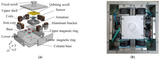
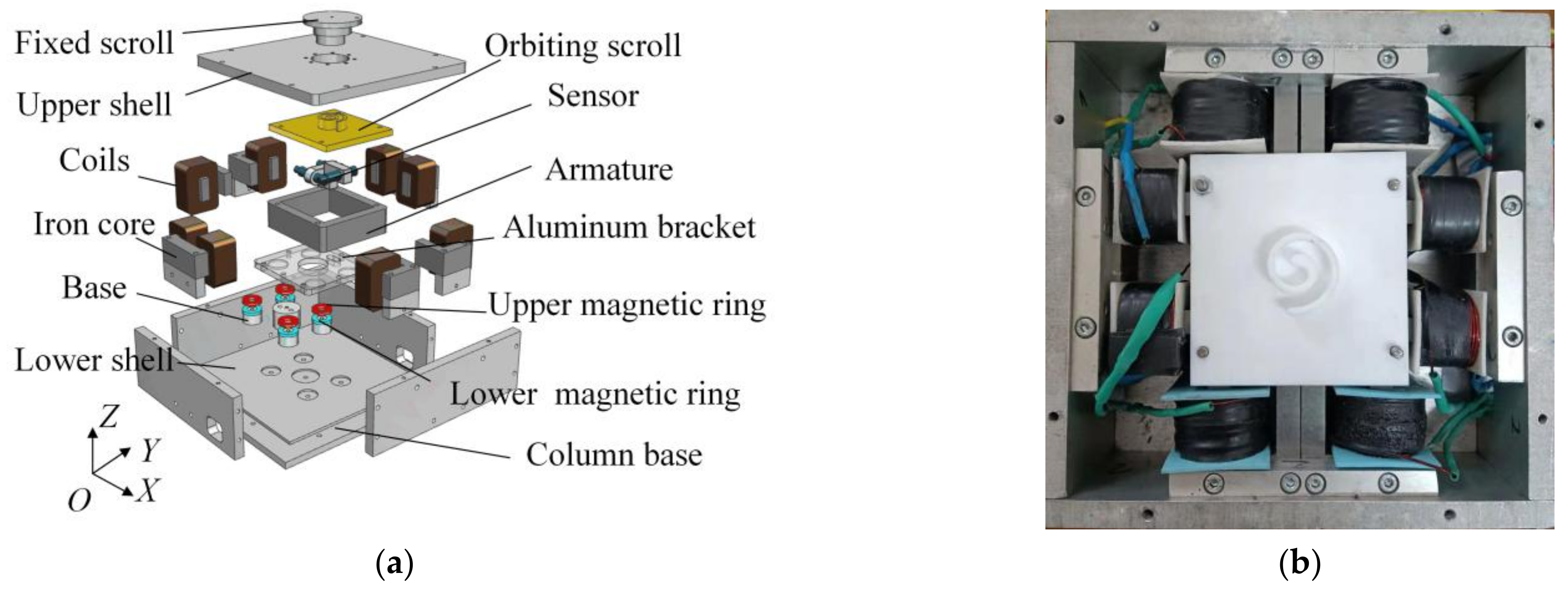
The structure of the MLDD-OFSC is shown in Figure 1a. The armature and orbiting scroll are driven horizontally by three pairs of electromagnets to perform the orbiting motion for gas compression. As shown in Figure 1b, three pairs of electromagnets are arranged in the X and Y directions around the armature. The two X-direction electromagnets are controlled to keep the displacements equal, thereby suppressing the self-rotation of the orbiting scroll and eliminating the need for anti-rotation mechanisms. The Y-direction electromagnet provides the driving force in the vertical axis of the orbital plane. The time-varying gas load requires a closed-loop servo system to stabilize the trajectory. Three displacement sensors are arranged around the armature: the Y-direction sensor measures the armature position, while the two X-direction sensors measure both position and rotation angle.
Figure 1.
Structure and operating principle of the MLDD-OFSC. (a) Cross-sectional view of the compressor; (b) photograph of the experimental prototype.
In the vertical direction, a passive permanent-magnet compliance mechanism, consisting of four sets of repulsive magnetic rings, supports the orbiting scroll. This flexible support absorbs impacts and vibrations. In addition, the orbiting scroll can tilt to release pressure when the compression chamber pressure becomes abnormally high, improving system safety.
2.2. Dynamic Modeling and Acceleration Feedback Linearization
The dynamics of the orbiting scroll in a single degree of freedom can be described by Newton’s second law:
where m is the mass of the orbiting scroll assembly, q denotes the translational DOF (x or y), γ is the yaw angle, and J is the rotational inertia. The lumped disturbance Fd,q is defined as:
where c is the viscous damping coefficient, Ffriction represents Coulomb friction, Fgas is the gas force from compression, and Fother accounts for unmodeled disturbances.
For each axis, a pair of opposing electromagnets is driven by a single current command ic with zero-bias differential distribution [28]:
The electromagnetic force generated by the active coil is nonlinear with respect to both current and air gap:
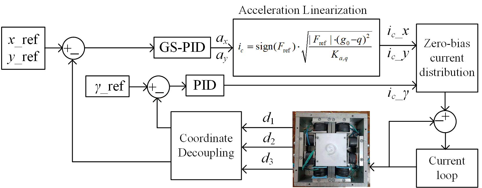
where Ka,q is the electromagnetic force coefficient, and g0 is the nominal air gap at the center position (1.5 mm). This nonlinearity—where the force is proportional to the square of the current and inversely proportional to the square of the air gap—motivates the acceleration feedback linearization approach. The key idea is to use an inverse force model to compute the current command required to produce a desired acceleration. Given a desired acceleration, the required electromagnetic force is:
Inverting (4) yields the current command:
By applying this current in real time, the nonlinear electromagnetic suspension system is compensated into a nominal double-integrator system , effectively linearizing the plant for the outer position loop.
2.3. Control System Architecture
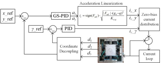
Figure 2 illustrates the overall control architecture of the proposed system. The control scheme comprises three cascaded loops: an outer position loop with gain-scheduled PID (GS-PID) control, a middle acceleration loop with inverse-model-based feedback linearization, and an inner current loop provided by the commercial servo drive hardware. In the feedback path, three eddy-current displacement sensors measure the distances to the orbiting scroll, and a homogeneous-transformation decoupling module converts the raw sensor signals into the actual three-DOF motions (x, y, and yaw angle γ), which are then fed back to the position loop for error computation. The current distribution follows a zero-bias differential driving scheme, where the single current command is distributed to the opposing electromagnets to enable bidirectional force generation. The gain scheduling strategy is detailed in Section 2.4, and the decoupling principle is described in Section 2.5.
Figure 2.
Block diagram of the proposed control architecture.
2.4. Gain Scheduling Strategy
The proportional and derivative gains are scheduled according to the trajectory phase. The maximum gain is assigned at the center of the air-gap stroke (1.5 mm, where the velocity is maximum), and the minimum gain at the stroke extremes (where the displacement error is maximum, and the velocity is zero). This design is motivated by the zero-bias differential driving configuration: a naive larger air gap to generate higher gain” scheduling would cause abrupt gain variations near the extremes, exciting mechanical oscillations. Placing the gain peak at the stroke center and decreasing it smoothly toward both ends compensates for stiffness degradation while avoiding switching-induced transients.
The position-loop GS-PID control law is as follows:
Define the air-gap offset Δx = x − x0, where x0 = 1.5 mm denotes the center air gap of the actuator stroke. A distance-based scheduling law, in which the gain decreases monotonically with |Δx|, can be formulated as:
where Δxmax = 1.0 mm is the maximum allowable air-gap offset. This law reaches its maximum at the stroke center and its minimum at both boundaries. However, it suffers from two fundamental drawbacks. First, it relies on |Δx|, which introduces a slope discontinuity at the stroke center and complicates theoretical analysis. Second, in the differential driving configuration where the two air gaps are complementary, a gain that varies with |Δx| would reach its extreme values precisely at the turning points, where the control direction reverses and the effective stiffness switches from one coil to the other—leading to abrupt gain jumps and mechanical oscillations.
To overcome these issues, a cosine-based continuous scheduling law is adopted as the final expression:
where Kp0 and Kd0 are the base gains, and Kp,amp and Kd,amp are the variation amplitudes. This mapping places the maximum gain at the stroke center, where the two coils are symmetrically balanced, and the electromagnetic stiffness is moderate, and smoothly reduces toward both extremes, where the force capability is inherently weak and a softer control action helps prevent collision. Moreover, the cosine function is smooth and continuously differentiable over the entire orbital cycle, avoiding the slope discontinuities and gain jumps inherent in displacement-based scheduling. Consequently, the gains vary at twice the trajectory frequency, completing two full scheduling cycles per orbital revolution.
2.5. Coordinate Decoupling
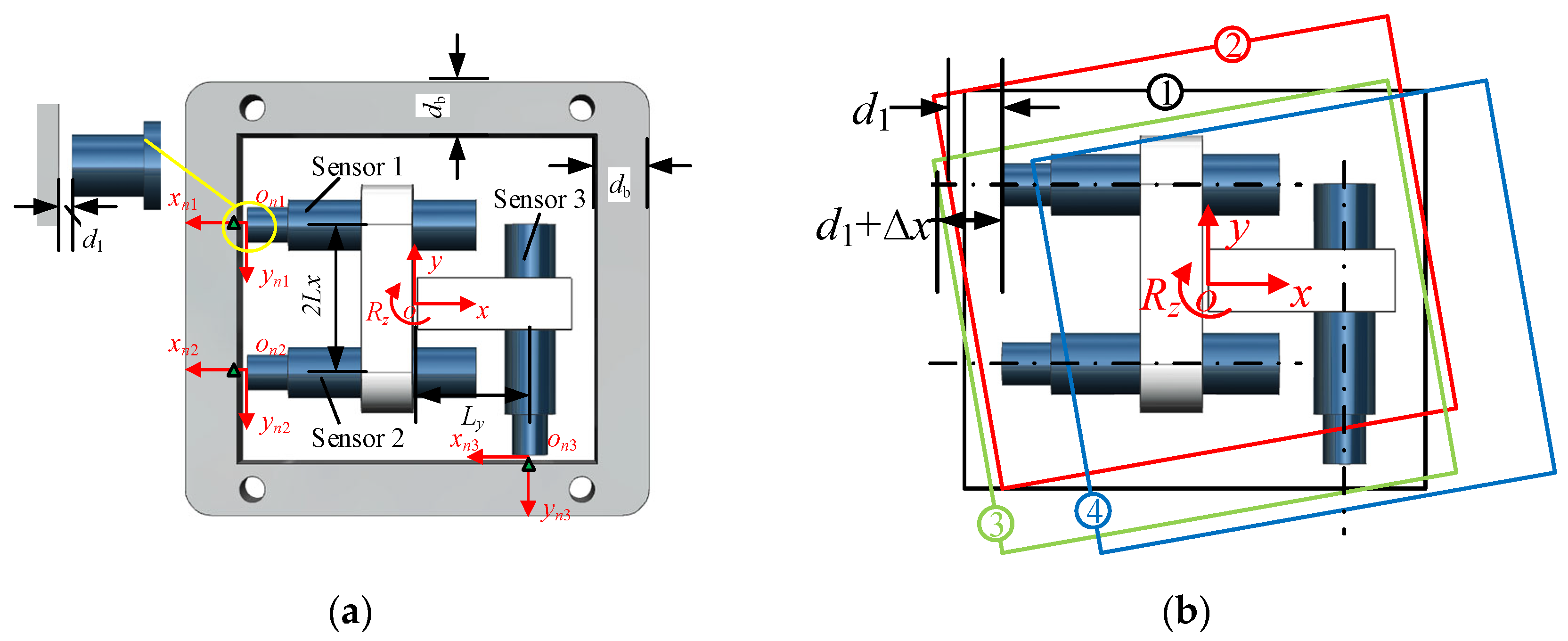
In the MLDD-OFSC, three displacement sensors are arranged around the orbiting scroll, measuring distances d1, d2, and d3. These raw sensor readings are not directly equal to the physical DOFs—each sensor measures a coupled combination of x, y, and yaw angle γ. To enable independent control, a decoupling transformation is required. The geometric relationship between the sensor readings and the physical DOFs is established through a homogeneous transformation matrix. Figure 3a illustrates the coordinate transformation from the original system {P} to each sensor coordinate system {A}, {B}, and {C}. For each sensor i (i = 1, 2, 3), this transformation is given by:
where txi and tyi are the translation offsets of each sensor, as shown in Figure 3b. The physical meaning of this coupling is illustrated: when the orbiting scroll undergoes displacement and rotation simultaneously, the sensor readings are no longer independent. Although d3 measures the distance in the Y direction, it is coupled with d1 and d2. The displacements in both X and Y directions are simultaneously governed by all three sensor readings d1, d2, and d3. This coupling implies that a naive decoupling approach—treating each sensor as representing a single DOF—would introduce significant errors during trajectory motion.
Figure 3.
Coordinate decoupling principle. (a) Schematic diagram of coordinate transformation. (b) Coordinate decoupling principle.
By inverting the homogeneous transformation, the physical DOFs can be reconstructed from the coupled sensor measurements. The resulting decoupling relationship is:
where Lx and Ly are geometric constants of the sensor arrangement, and Dx and Dy are offset parameters. This transformation decouples the raw sensor signals into three independent DOFs, enabling the position loop to control x, y, and γ separately without cross-coupling interference.
2.6. Frequency-Domain Stability Verification
To verify the closed-loop stability of the gain-scheduled PID parameters over the full operating range, frequency-domain analysis is performed at three characteristic air-gap positions: at the left extreme (0.5 mm), center (1.5 mm), and right extreme (2.5 mm). The corresponding PID gains at these positions are at both extremes, and at the center, with fixed across all positions. For frequency-domain analysis, the nonlinear electromagnetic force model in Equation (4) is linearized at each operating point. The current stiffness Ki(x0) and displacement stiffness Kx(x0) (negative stiffness magnitude) are defined as:
where Kb = 1.7 × 10⁻⁵ N·m2/A2 is the electromagnetic force coefficient, g0 = 1.5 mm is the nominal center air gap, δ = 0.5 mm is a gap compensation coefficient, and I0 = 1.0 A is the fixed bias current.
The open-loop transfer function L(s) is explicitly expressed as:
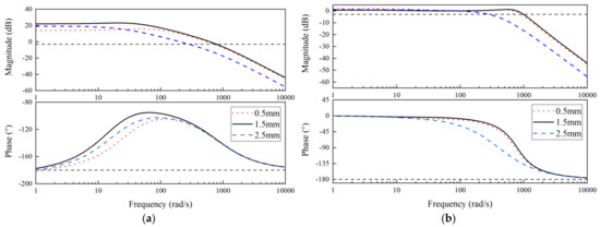
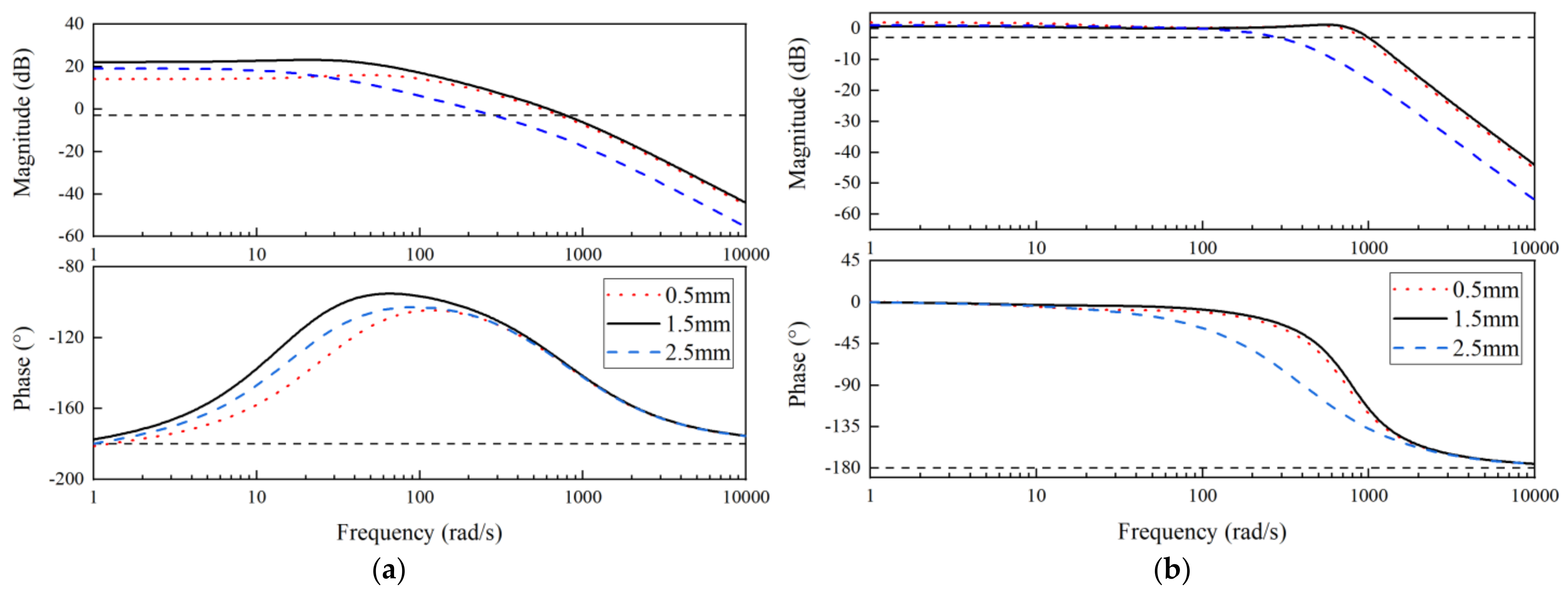
Figure 4a presents the open-loop Bode plots for the three positions, with the 0 dB and −180° reference lines marked for gain margin (GM) and phase margin (PM) evaluation. The left extreme and center positions yield PMs of 53.55° and 52.02°, with GMs of −14.06 dB and −22.09 dB, respectively. The right extreme position exhibits a PM of 72.77° and a GM of −19.16 dB. The negative GM values are expected for this open-loop unstable plant, since the open-loop transfer function contains a right-half-plane pole, and stability cannot be inferred from the sign of the GM alone. Figure 4b shows the corresponding closed-loop Bode plots, from which the bandwidths are extracted as 130.9 Hz, 153.1 Hz, and 43.9 Hz, respectively. All phase margins are positive, with a minimum of 52.02°, indicating adequate robustness. More rigorously, stability is verified by the closed-loop pole locations: at all three positions, all closed-loop poles lie strictly in the left half-plane (see Table 1). The combination of positive phase margins, negative GM (consistent with an open-loop unstable plant), and strictly stable closed-loop poles confirms that the closed-loop system remains stable with adequate robustness margins under the proposed gain-scheduled PID parameters across the entire air-gap stroke.
Figure 4.
Frequency-domain analysis at three characteristic air-gap positions. (a) Open-loop Bode plots with PM and GM annotations. (b) Closed-loop Bode plots for bandwidth evaluation.
Table 1.
Frequency-domain stability margins and closed-loop pole locations at three air-gap positions.
3. Simulation Analysis
The simulation compares three controllers: traditional fixed-gain PID, acceleration-linearized PID (AL_PID) with fixed gains, and the proposed AL_GS_PID. For the traditional PID controller, the gains are set to , , and . For the AL_PID controller, the gains are , , and . For the proposed AL_GS_PID controller, the gain scheduling follows the cosine-based mapping defined in Section 2.4, with , , , , and fixed.
The simulation model incorporates the current-loop dynamics identified in Section 2.6 and a lumped friction model to approximate the experimental platform. The friction is modeled as a Coulomb-viscous combination with N. The current command is limited to A. All other system parameters are consistent with Section 2.6. For clarity, the complete set of simulation parameters is summarized in Table 2.
Table 2.
Parameters used in the simulation model.
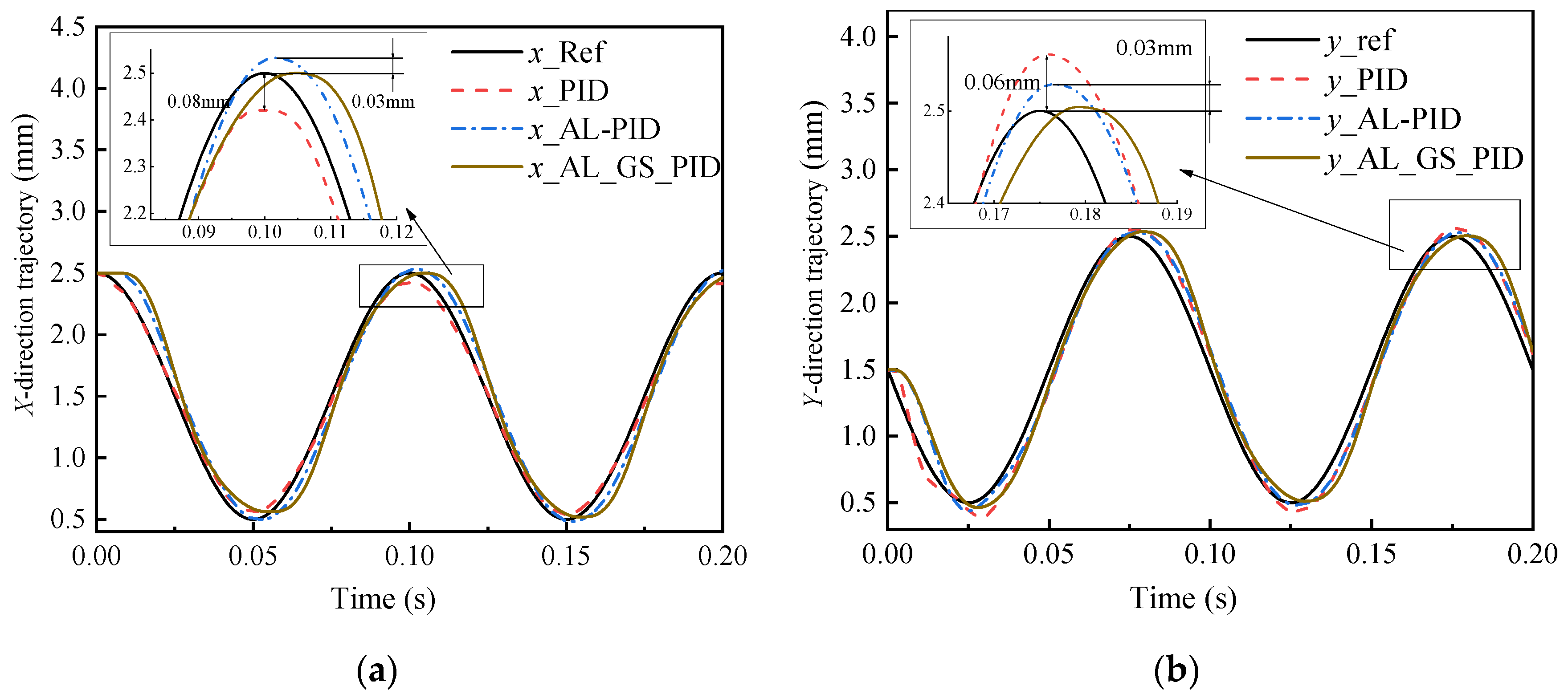
As shown in Figure 5, the tracking performance improves progressively from traditional PID to AL_PID to AL_GS_PID. In the X-direction, the peak errors are 0.08 mm for traditional PID, 0.03 mm for AL_PID, and near-zero for AL_GS_PID. In the Y-direction, the peak errors are 0.06 mm for traditional PID, 0.03 mm for AL_PID, and near-zero for AL_GS_PID. The AL_GS_PID achieves the smallest errors with virtually no overshoot, demonstrating the effectiveness of the proposed gain-scheduled control strategy.
Figure 5.
Simulated trajectory tracking comparison. (a) X-direction trajectory; (b) Y-direction trajectory.
4. Experimental Results
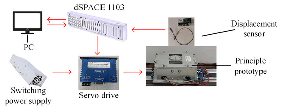
All experiments were conducted on the MLDD-OFSC test rig shown in Figure 6. The system consists of a dSPACE 1103 real-time controller, a Copley JSP-180-10 servo drive (operating in current mode) powered by a switching power supply (S-2000-220, DC 220 V/9 A), three eddy-current displacement sensors (AEC Pu-05, 0–2 mm range, 0.5 μm resolution), and the MLDD-OFSC prototype. The reference trajectory is a circle with a radius of 0.5 mm at 600 rpm. The controller is implemented in Simulink and compiled to the dSPACE platform at a sampling rate of 1 kHz. The servo drive accepts ±10 V analog command signals, with the output current limited to ±5 A.
Figure 6.
Experiment platform of the MLDD-OFSC.
4.1. Decentralized PID Control Without Decoupling
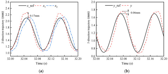
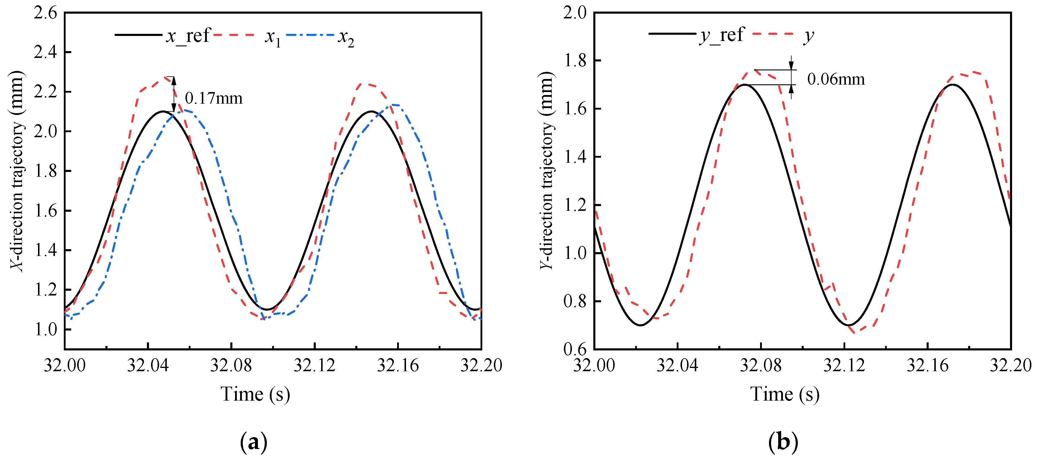
Figure 7a,b shows the X- and Y-direction trajectories under conventional decentralized PID control. The controller employs fixed parameters Kp = 8000, Ki = 500, and Kd = 20 for all three channels (X, Y, and yaw), with no decoupling between the translational and rotational degrees of freedom. The measured trajectory exhibits a visibly distorted elliptic shape, deviating significantly from the reference circle. The peak tracking errors are 0.17 mm in X and 0.06 mm in Y. This result confirms that without decoupling, the coupling between sensor readings and the three DOFs severely corrupts the orbital shape, and the independent channel controllers cannot suppress the resulting self-rotation and trajectory distortion.
Figure 7.
Experimental trajectory tracking: decentralized PID without decoupling. (a) X-direction trajectory; (b) Y-direction trajectory.
4.2. PID Control with Homogeneous-Transformation Decoupling
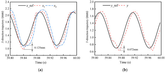
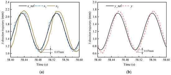
Figure 8a,b presents the results when the homogeneous-transformation decoupling module is introduced. The PID parameters remain unchanged from Experiment I (Kp = 8000, Ki = 500, Kd = 20) to isolate the effect of decoupling. After decoupling, the elliptical distortion is substantially reduced, and the trajectory recovers a near-circular shape. The peak errors decrease to 0.125 mm in X and 0.072 mm in Y. This improvement verifies that the decoupling strategy effectively separates the coupled sensor signals into independent X, Y, and yaw DOFs. However, residual periodic errors persist, indicating that the nonlinear electromagnetic stiffness has not yet been addressed.
Figure 8.
Experimental trajectory tracking: PID with homogeneous-transformation decoupling. (a) X-direction trajectory; (b) Y-direction trajectory.
4.3. Acceleration-Feedback Linearization with Fixed-Gain PID
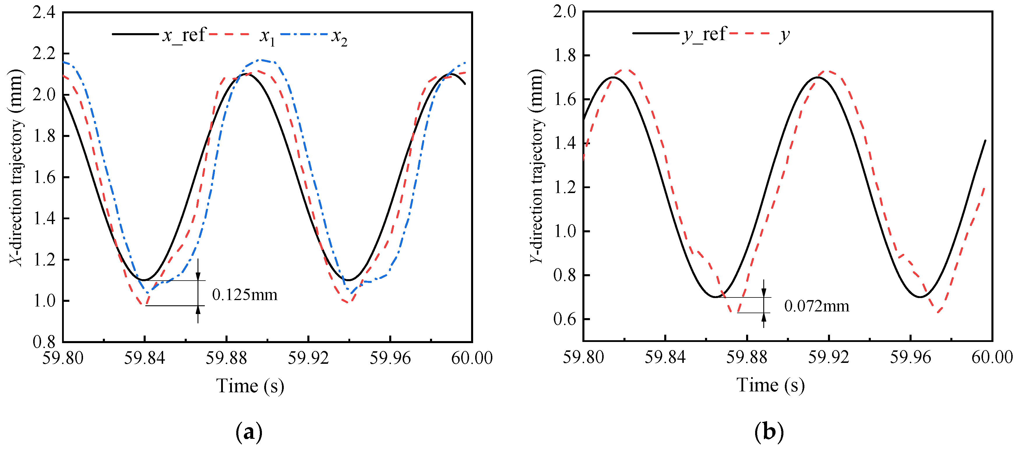
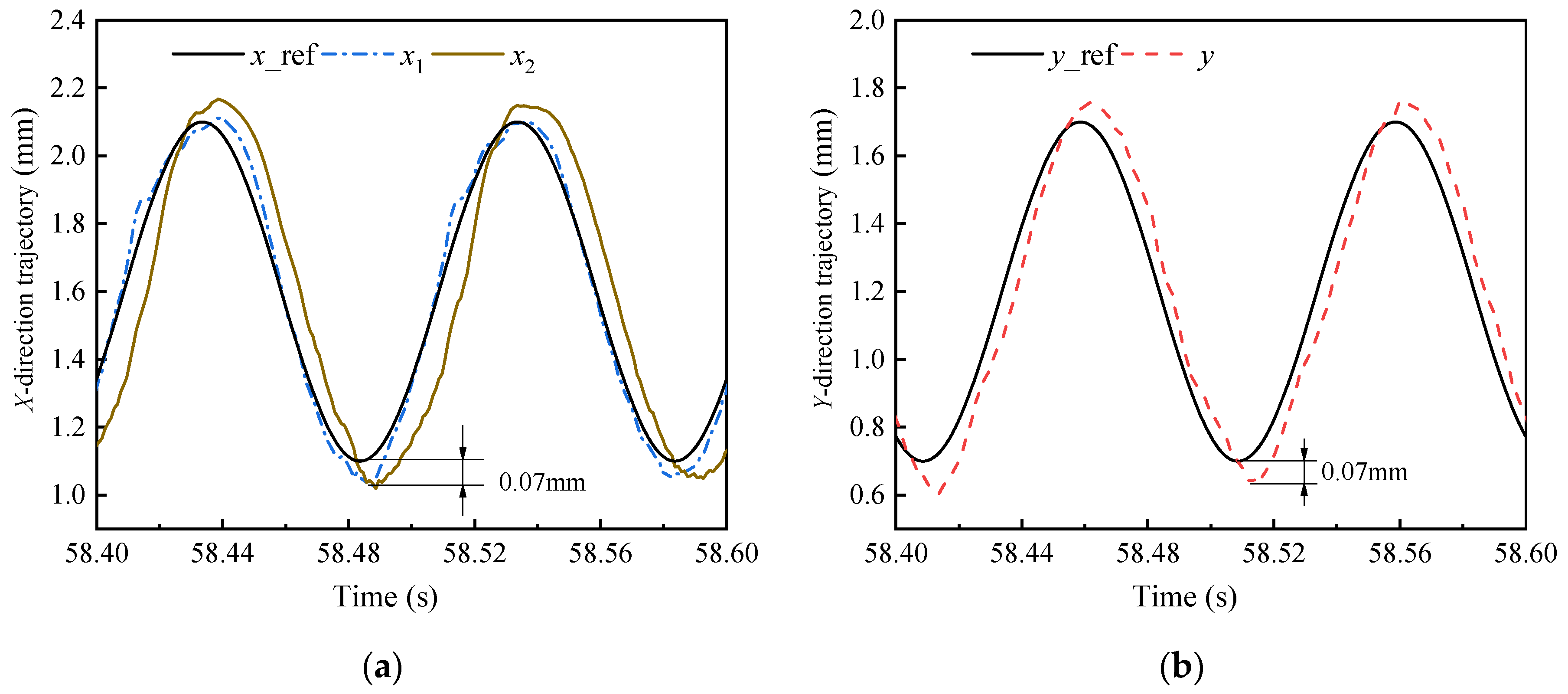
Figure 9a,b shows the results when the acceleration-feedback linearization module is added on top of the decoupling stage. The outer-loop PID adopts fixed gains of , , and . The linearization effectively compensates for the air-gap-dependent force nonlinearity near the stroke center, yielding tighter tracking and faster transient response during the mid-phase of the orbit. The peak errors are reduced to 0.07 mm in both X and Y directions. Compared with Experiment II, the linearization brings clear benefits in the central region. However, at the stroke extremes where the air-gap offset is maximal, the fixed gains cannot accommodate the varying stiffness, resulting in visible error growth. This confirms that fixed-gain linearization alone is insufficient to ensure uniform performance over the full trajectory cycle.
Figure 9.
Experimental trajectory tracking: AL_PID with fixed gains. (a) X-direction trajectory; (b) Y-direction trajectory.
4.4. Acceleration-Feedback Linearization with Gain-Scheduled PID
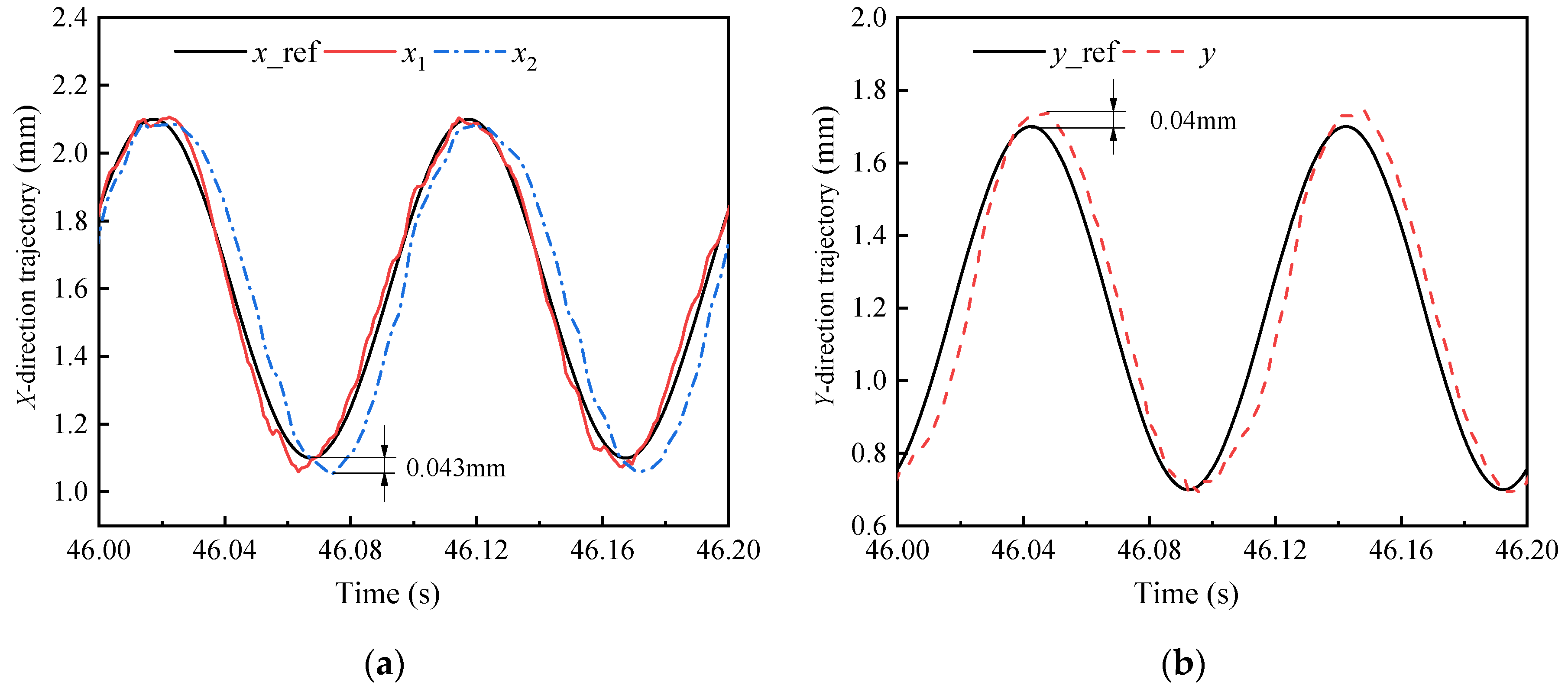
Figure 10a,b presents the results of the full proposed scheme: decoupling plus acceleration feedback linearization with gain-scheduled PID (AL_GS_PID). The proportional and derivative gains for the X and Y channels are scheduled as and according to the trajectory phase, with , , , , and fixed. The yaw channel retains fixed gains of , , and . The adaptive strategy achieves the most consistent tracking performance across the entire orbital cycle. The trajectory maintains near-perfect circularity with minimal overshoot. The peak errors are reduced to 0.043 mm in X and 0.04 mm in Y—the lowest among all four experiments. Notably, the fixed gains used in Experiment III (, ) exactly equal the upper bounds of the adaptive intervals in Experiment IV. Therefore, the superiority of Experiment IV over Experiment III cannot be attributed to higher control effort, but purely to the phase-dependent gain scheduling that dynamically matches the time-varying stiffness.
Figure 10.
Experimental trajectory tracking: AL_GS_PID with phase-adaptive gains. (a) X-direction trajectory; (b) Y-direction trajectory.
5. Discussion
The statistical metrics in Table 3 confirm the progressive improvement across the four control configurations. Decentralized PID exhibits the largest errors and highest current (4.50 A). Decoupling alone reduces X-direction errors but slightly increases Y-direction errors, indicating that the coupling is eliminated at the cost of reduced cross-axis compensation. Adding acceleration linearization further reduces errors to 0.07 mm near the stroke center. The proposed AL_GS_PID achieves the lowest RMS and STD in both directions while using the lowest current (2.83 A), confirming that the performance improvement arises from scheduling rather than higher control effort.
Table 3.
Experimental tracking performance and control effort.
6. Conclusions
This paper has proposed a control strategy integrating coordinate decoupling, acceleration feedback linearization, and gain-scheduled PID for a magnetically levitated oil-free scroll compressor. The main conclusions are drawn as follows:
- (1)
- Coordinate decoupling effectively eliminates trajectory distortion. A homogeneous-transformation-based decoupling model is established to convert three raw sensor readings into independent X, Y, and yaw DOFs. With identical PID gains, the decoupling module reduces the peak tracking errors from 0.17 mm to 0.125 mm in the X-direction and from 0.06 mm to 0.072 mm in the Y-direction, confirming that the improvement arises from decoupling itself rather than controller retuning.
- (2)
- Acceleration feedback linearization compensates for the nonlinear force–air-gap relationship. By inverting the electromagnetic force model, the suspension dynamics are linearized into a nominal double-integrator system. The fixed-gain AL_PID further reduces the peak errors to 0.07 mm in both directions near the stroke center, demonstrating the effectiveness of the nonlinear compensation.
- (3)
- Phase-adaptive gain-scheduled PID accommodates air-gap-dependent stiffness variation. A cosine-based smooth scheduling law is developed, where the gains vary continuously with the trajectory phase to avoid abrupt transitions. The full AL_GS_PID scheme achieves the best tracking performance, with peak errors of 0.043 mm in X and 0.04 mm in Y—reductions of 74.7% and 33.3% over the decentralized PID. Notably, the scheduled gains in Experiment IV share the same upper bounds as the fixed gains in Experiment III (Kp = 8000, Kd = 20), confirming that the improvement is attributed to phase-dependent scheduling rather than higher control effort.
- (4)
- Frequency-domain analysis verifies closed-loop stability across the full stroke. At three characteristic air-gap positions (0.5 mm, 1.5 mm, and 2.5 mm), the open-loop Bode plots yield phase margins of 53.55°, 52.02°, and 72.77°, respectively, with corresponding gain margins of −14.06 dB, −22.09 dB, and −19.16 dB. The negative GM values were expected for this unstable open-loop plant. More rigorously, all closed-loop poles were verified to lie strictly in the left half-plane at all three positions, confirming robust stability.
- (5)
- The proposed strategy achieves improved tracking with reduced control effort. The maximum control current of the AL_GS_PID is 2.83 A, lower than the 4.50 A required by the decentralized PID, further demonstrating that the performance enhancement is achieved through intelligent gain scheduling rather than excessive actuation.
The proposed strategy was validated under no-load conditions, where gas-force effects are negligible. Extension to full-load operation requires further investigation and is not addressed in this work.
Author Contributions
Conceptualization, C.S. and F.S.; methodology, C.S. and F.S.; software, C.S. and J.Y.; validation, C.S., J.Y., C.Z. and R.D.; formal analysis, C.S. and J.J.; investigation, C.S., X.L., and F.X. and R.D.; data curation, J.Y., X.L., and C.Z.; writing—original draft preparation, C.S. and J.Y.; writing—review and editing, C.S., F.S., R.Z., F.X., R.D. and L.K.; visualization, J.Y., X.L., and C.Z.; supervision, F.S. and F.X.; project administration, F.S.; funding acquisition, F.S.; resources, L.K. All authors have read and agreed to the published version of the manuscript.
Funding
This research was supported by the National Natural Science Foundation of China (Grant Nos. 52375258 and 52405284), the Liaoning Provincial Science and Technology Program (Grant No. 2025-BSLH-300), the National Key Research and Development Project (Grant No. 2024YFB3410002), the China Postdoctoral Science Foundation (Grant No. 2024M762160), the Natural Science Foundation of Liaoning Province (Grant No. 2023-BS-127), and the Scientific Research Fund Project of the Liaoning Provincial Department of Education (Grant No. JYTMS20231191).
Institutional Review Board Statement
Not applicable.
Informed Consent Statement
Not applicable.
Data Availability Statement
The original contributions presented in this study are included in the article. Further inquiries can be directed to the corresponding author.
Conflicts of Interest
The authors declare no conflicts of interest.
References
- Wang, J.; Han, Y.; Pan, S.; Wang, Z.; Cui, D.; Geng, M. Design and development of an oil-free double-scroll air compressor used in a PEM fuel cell system. Renew. Energy 2022, 199, 840–851. [Google Scholar] [CrossRef] [Scilit]
- Cardone, M.; Gargiulo, B. Numerical simulation and experimental validation of an oil-free scroll compressor. Energies 2020, 13, 5863. [Google Scholar] [CrossRef] [Scilit]
- Cheng, S.; Feng, Y.; Wang, K.; Meng, X. Tribo-dynamics modeling and analysis of key friction pairs in scroll compressor with floating fixed scroll design. Eng. Appl. Comput. Fluid Mech. 2022, 16, 2270–2285. [Google Scholar] [CrossRef] [Scilit]
- Hong, J.; He, X.; Sun, C.; Zhang, D.; Tao, W. Exploration of refrigerant vapor–lubricating oil two-phase flow in a scroll compressor. Phys. Fluids 2024, 36, 123321. [Google Scholar] [CrossRef] [Scilit]
- He, Z.; Ji, L.; Xing, Z. Experimental investigation on the DLC film coating technology in scroll compressors of automobile air conditioning. Energies 2020, 13, 5103. [Google Scholar] [CrossRef] [Scilit]
- Zhang, Y.X.; Chen, X.H.; Li, J.; Li, C.M.; Li, X.; Gao, T.; Jing, T.T.; Liu, W. Tribological properties of PEEK-based composite coating prepared by thermal spraying. Phys. Scr. 2023, 98, 055923. [Google Scholar] [CrossRef] [Scilit]
- Schweitzer, G.; Maslen, E.H. Magnetic Bearings: Theory, Design, and Application to Rotating Machinery; Springer: Berlin/Heidelberg, Germany, 2009. [Google Scholar]
- Dutta, D.; Biswas, P.K.; Debnath, S.; Ahmad, F. Advancements and challenges in active magnetic bearings: A comprehensive review of performance, control, and future prospects. IEEE Access 2024, 13, 3051–3071. [Google Scholar] [CrossRef] [Scilit]
- Fan, L.; Liu, Z.; Jiang, D.; Qu, R. Research on high-frequency vibration reduction for active magnetic bearings with carrier phase shifting PWM. IEEE Trans. Ind. Electron. 2024, 71, 8525–8535. [Google Scholar] [CrossRef] [Scilit]
- Fan, L.; Liu, Z.; Qu, R. Online vibration control for active magnetic bearing-based motor drive with improved grey wolf optimization. IEEE Trans. Ind. Electron. 2026, 73, 5203–5213. [Google Scholar] [CrossRef] [Scilit]
- Ma, X.; Zheng, S.; Wang, K. Surge disturbance suppression of active magnetic bearing suspended compressors based on disturbance observer. IEEE Trans. Ind. Electron. 2023, 70, 9421–9431. [Google Scholar] [CrossRef] [Scilit]
- Yan, Z.; Chen, Q.; Zheng, S. Method for enhancing the stability margin of the magnetic bearing-rotor system based on a novel low-frequency phase shifter. IEEE Trans. Ind. Electron. 2025, 72, 2289–2299. [Google Scholar] [CrossRef] [Scilit]
- Li, W.; Zhu, C. Multiobjective vibration control for the noncollocated active magnetic bearings flexible rotor systems. IEEE Trans. Ind. Electron. 2024, 71, 8525–8535. [Google Scholar] [CrossRef] [Scilit]
- Trakarnchaiyo, C.; Wang, Y.; Khamesee, M.B. Design of a compact planar magnetic levitation system with wrench–current decoupling enhancement. Appl. Sci. 2023, 13, 2370. [Google Scholar] [CrossRef] [Scilit]
- Lv, X.; Fang, J. Gain-Scheduling Robust Control for High-Speed Flat Magnetically Suspended Rotor of MSCMG Considering Gyroscopic Effects and Dynamic Characteristics. IEEE Trans. Ind. Electron. 2025, 72, 5398–5407. [Google Scholar] [CrossRef] [Scilit]
- Hosseinzadeh, R.; Martin, F.; Hinkkanen, M. A dynamic model for six-degree-of-freedom bearingless linear motor systems. IEEE Trans. Ind. Appl. 2021, 57, 6921–6930. [Google Scholar] [CrossRef] [Scilit]
- Xu, F.; Lv, Y.; Xu, X.; Dinavahi, V. FPGA-based real-time wrench model of direct current driven magnetic levitation actuator. IEEE Trans. Ind. Electron. 2018, 65, 9635–9645. [Google Scholar] [CrossRef] [Scilit]
- Shi, C.; Sun, F.; Dou, R.; Ren, H.; Li, Q.; Xu, F.; Zhang, X. Modeling and simulation analysis of oil-free scroll compressor driven by magnetic force. Int. J. Appl. Electromagn. Mech. 2020, 64, 1269–1278. [Google Scholar] [CrossRef] [Scilit]
- Shi, C.; Sun, F.; Xu, F.; Jin, J.; Tong, L.; Zhou, Q.; Oka, K. Analysis of trajectory tracking characteristics of a magnetically driven oil-free scroll compressor. Actuators 2022, 11, 312. [Google Scholar] [CrossRef] [Scilit]
- Su, K.H.; Park, K.; Son, Y.S.; Lee, Y. Performance optimization with LPV synthesis for disturbance attenuation in planar motors. Mathematics 2024, 12, 3293. [Google Scholar] [CrossRef] [Scilit]
- Almobaied, M.; Al-Nahhal, H.S.; Arrieta, O.; Vilanova, R. Design a robust proportional-derivative gain-scheduling control for a magnetic levitation system. Mathematics 2023, 11, 4040. [Google Scholar] [CrossRef] [Scilit]
- Trakarnchaiyo, C.; Khamesee, M.B. A novel wrench–current decoupling strategy to extend the use of small lookup data for a long-range maglev planar motor. Actuators 2023, 12, 358. [Google Scholar] [CrossRef] [Scilit]
- Zhu, M.; Wang, X.; Bao, X.; Zhou, H. Decoupling Control Strategy for Maglev Planar Motors Based on Virtual Current Coordinate System. In Proceedings of the 2025 28th International Conference on Electrical Machines and Systems (ICEMS), Busan, Republic of Korea, 16–19 November 2025; pp. 1033–1038. [Google Scholar] [CrossRef] [Scilit]
- Zhuravlev, A.; Putkonen, A.; Madanzadeh, S.; Jastrzebski, R.P. Linear parameter-varying and fixed-parameter H∞-based control of a bearingless compressor. IEEE Access 2024, 12, 104344–104353. [Google Scholar] [CrossRef] [Scilit]
- Tarisciotti, L.; Ahumada, C.; Papini, L.; Gonzalez-Castaño, C.; Bolognesi, P. Finite control set model predictive control for a wheatstone bridge active magnetic bearing. IEEE Trans. Ind. Appl. 2025, 61, 7504–7516. [Google Scholar] [CrossRef] [Scilit]
- Gong, L.; Luo, W.; Li, Y.; Chen, J.; Hua, Z. Rotor unbalanced vibration control of active magnetic bearing high-speed motor via adaptive fuzzy controller based on switching notch filter. Appl. Sci. 2025, 15, 3681. [Google Scholar] [CrossRef] [Scilit]
- Zhang, Y.; Xu, Y.; Zhou, J.; Zhou, Y.; Mahfoud, J. Vibration control of AMB-rotor system under base motions based on disturbance observer. IEEE ASME Trans. Mechatron. 2025, 30, 5398–5407. [Google Scholar] [CrossRef] [Scilit]
- Yao, Y.; Ren, G.; Yu, S. Division linearization zero-bias current control for AMBs–rotor system with uncertainties and saturation. IEEE Trans. Ind. Electron. 2023, 70, 10557–10566. [Google Scholar] [CrossRef] [Scilit]

Disclaimer/Publisher’s Note: The statements, opinions and data contained in all publications are solely those of the individual author(s) and contributor(s) and not of MDPI and/or the editor(s). MDPI and/or the editor(s) disclaim responsibility for any injury to people or property resulting from any ideas, methods, instructions or products referred to in the content. |
© 2026 by the authors. Licensee MDPI, Basel, Switzerland. This article is an open access article distributed under the terms and conditions of the Creative Commons Attribution (CC BY) license.