


Abstract
A flywheel energy storage system (FESS) is a device that employs a high-speed rotating flywheel for energy storage, where the motor is a core component enabling the energy conversion. Since the motor rotor is integrated onto the flywheel rotor (FR), when the FESS operates, the vortex motion of the FR causes misalignment between the motor rotor and stator, and the resulting unbalanced magnetic pull (UMP) will induce changes in the vibration characteristics of the FR. This paper presents a permanent magnet synchronous motor (PMSM) designed for a FESS and analyzes the variation pattern of the UMP induced by rotor eccentricity in this motor utilizing the finite element method. Furthermore, the UMP is equivalently modeled using the motor stiffness, and a dynamic model of an active magnetically suspended rigid flywheel rotor that considers the UMP in the motor is established. In this study, the motor position offset ratio β is defined to quantify the axial distance between the motor position and the FR mass center. This paper analyzes the variation law of the vibration characteristics of the FR with the magnitudes of the UMP and the motor position offset ratio β using numerical calculations. Finally, the correctness of the calculated results is verified using experimental testing. This investigation demonstrates that the value of UMP fluctuates as the rotor’s rotation angle increases, while its average value exhibits a linear increasing trend with the growth in rotor eccentricity. As UMP and β increase, the first- and second-order critical speeds of FR exhibit a clear decreasing trend. Meanwhile, variations in these two factors also exert different influences on the vibration amplitude induced by the mass imbalance response of the FR. Therefore, when designing an active magnetically levitated flywheel energy storage system, the influence of motor parameters on the vibration characteristics of FR should be taken into consideration.
1. Introduction
A flywheel energy storage system (FESS) is an innovative physical energy storage device that employs a high-speed rotating flywheel to store energy and realizes the conversion between electrical energy and kinetic energy through a motor. It boasts the strengths of a large energy storage capacity density, high charging and discharging capacity, fast response speed, environmental friendliness, and long working life. In addition, it offers excellent practical engineering application value [1,2,3].
Motor design is a crucial task for the development of a FESS. Based on the application requirements of the FESS, the motor should be capable of both electric and power generation modes and possess high power, fast response speed, and high reliability. The motors commonly applied in flywheel energy storage systems include permanent magnet synchronous motors (PMSMs), induction motors (IMs), and switched reluctance motors (SRMs) [4,5,6]. In FESSs, the motor rotor is often integrated into the flywheel rotor shafting. When the flywheel rotor rotates, shafting vortex occurs in the motor rotor. This causes misalignment between the rotor and stator of the motor. The electromagnetic interaction between the motor rotor and stator not only generates torque but also produces a radial attractive force. When the rotor is concentric with the stator, this radial attractive force is balanced. However, when the rotor and stator are in a non-concentric state, unbalanced magnetic pull (UMP) will be generated [7,8,9]. During the operation of the FESS, the motor rotor is inevitably subjected to the action of UMP, which will further affect the vibration properties of the FR [10,11]. Therefore, when designing the motor for FESSs, it is necessary to investigate its operating performance and also consider the influence of UMP on the vibration characteristics of the FR. In recent years, many scholars have conducted extensive research on the design of flywheel energy storage system motors, the UMP in motors, and the vibration properties of motor rotors.
Numerous investigations on the performance of motors in FESSs have been reported. Liu et al. [12] achieved an improvement in the performance and a reduction in the loss of an outer rotor ironless brushless DC motor by optimizing its magnetic poles and windings. Sun et al. [13,14,15] proposed a cup-shaped winding permanent magnet synchronous motor (PMSM) applied to a large-capacity FESS that could effectively decrease the axial height of flywheel and achieve an increase in the efficiency as well as a reduction in power consumption of the FESS. Wang et al. [16] optimized the rotor structure of the permanent magnet synchronous motor in a FESS, achieving a reduction in harmonic current and temperature on the rotor, effectively avoiding irreversible demagnetization of the permanent magnet. Chen et al. [17] designed a composite rotor of a PMSM with high speed for an 200 kW/20,000 rpm uninterruptible power supply flywheel energy storage system. This composite rotor could suppress eddy current losses in rotor and solve the heat dissipation problem. Li et al. [18] conducted multi-objective optimization on the structural parameters of the high-speed surface-mounted permanent magnet synchronous motor (SMPSM) in a magnetically suspended flywheel energy storage system, thereby improving the efficiency of the SMPSM and reducing its weight and torque ripple. Jiang et al. [19] designed a dual three-phase stator winding structure and auxiliary teeth for the PMSM used in FESSs, ensuring the motor’s fault tolerant operation under a series of winding open circuit faults, effectively reducing the current during winding short circuits, and thus improving the operational stability of motor.
During research on the vibration characteristics of the rotor, the bearing parameters, the frame support system, and the foundation excitation have important effects on the vibration characteristics of the rotor [20,21]. In addition, the unbalanced magnetic pull force of the motor has an important impact on the vibration characteristics of the rotor. Li et al. [22] proposed an analytical calculation model for the eccentricity air gap magnetic flux density in the slotted permanent magnet motor rotor that could quickly and accurately determine the corresponding magnetic field and unbalanced magnetic pull force under the condition of rotor eccentricity. Song et al. [23] adopted a FEM to study the UMP distribution of a motor rotor under different eccentricity conditions. The investigation revealed that the distributions of unbalanced magnetic pull force under static, dynamic, and mixed eccentricities were strip shaped, concentric and circular, and eccentric tooth shaped, respectively Zhang et al. [24] investigated the dynamic characteristics of the energy storage flywheel rotor when there was initial static eccentricity in the induction motor rotor. The study suggested that the static eccentricity would change the displacement waveform of the rotor as well as the shape and position of the axis trajectory. Furthermore, the frequency components related to the stator rotating magnetic field appeared in the rotor vibration spectrum, and new resonance peaks appeared in the acceleration response of the rotor. Xu et al. [25] proposed an air gap length model considering static and dynamic eccentricity and determined the UMP solution method. Subsequently, they established a rotor dynamics model considering this UMP; they also studied the vibration responses of the rotor under large and small relative eccentricity conditions. Liu et al. [26] reported a rotor system dynamics model considering the mass eccentricity, position eccentricity, angular eccentricity, as well as transverse electromagnetic torque of PMSM rotor, and these researchers also studied the vibration response of the motor rotor. The research indicated that various eccentricities of the motor rotor, unbalanced magnetic pull force, and lateral electromagnetic torque would cause the radial and inclined vibration coupling of the motor rotor. Hao et al. [27] built a dynamic model of the electric spindle system and investigated the influence of factors such as internal motor parameters, rotor static eccentricity, and bearing parameters on the dynamic characteristics of the spindle rotor. It demonstrated that the variation in the static eccentricity of the rotor caused the amplitude curve to exhibit complex nonlinear phenomena. Dai et al. [28] researched the nonlinear dynamical characteristics of the PMSM rotor, revealing the affect patterns of the UMP and mass eccentricity excitation on rotor vibration properties. Michon et al. [29] conducted a study on the UMP of the rotor and stator in a large permanent magnet motor and the impact of this force on the bearing’s load and lifespan. The results showed that the UMP had a pronounced effect on the lifespan of bearing. Feng et al. [30] proposed a semi-analytical method to describe the UMP force of a tilted eccentric rotor and its electromagnetic torque, established a rotor dynamics model for the spindle bearing unit, and also explored its dynamic displacement eccentric vibration response. The results demonstrated that the coupling effect of the UMP, mass unbalance force, as well as bearing force had a significant impact on the spindle bearing system.
Currently, although researchers have conducted relevant studies on the unbalanced magnetic pull (UMP) of motors in FESSs and the impact of this force on rotor vibration characteristics, there are relatively few investigations into the impact of motor UMP on the vibration characteristics of the FR in active magnetic-suspended flywheel energy storage systems. Therefore, this article first analyzes the characteristics of the UMP induced by rotor eccentricity in motor and then explores the effect of UMP in the motor on vibration characteristics of the rotor in an active magnetically levitated flywheel energy storage system.
The layout of this article is arranged as follows: Part 2 introduces the permanent magnet synchronous motor structure employed in the FESS and analyzes the variation rules of the unbalanced magnetic pull (UMP) under various rotor eccentricities in the motor using the finite element method. Furthermore, the unbalanced magnetic pull force (UMP) is equivalently treated. Part 3 constructs the dynamic model of an active magnetically suspended rigid flywheel rotor considering the UMP in the motor. Part 4 analyzes the influence of the UMP on the critical speed and mass imbalance response of the FR. Part 5 introduces the experimental platform and the test procedure and compares the theoretical values with measured data. Part 6 presents the conclusions of this paper.
2. Analysis of Unbalanced Magnetic Pull Force Caused by Rotor Eccentricity in a Permanent Magnet Synchronous Motor
2.1. Problem Description and Analysis
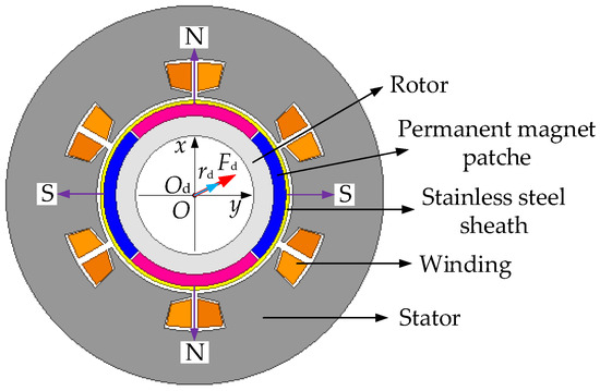
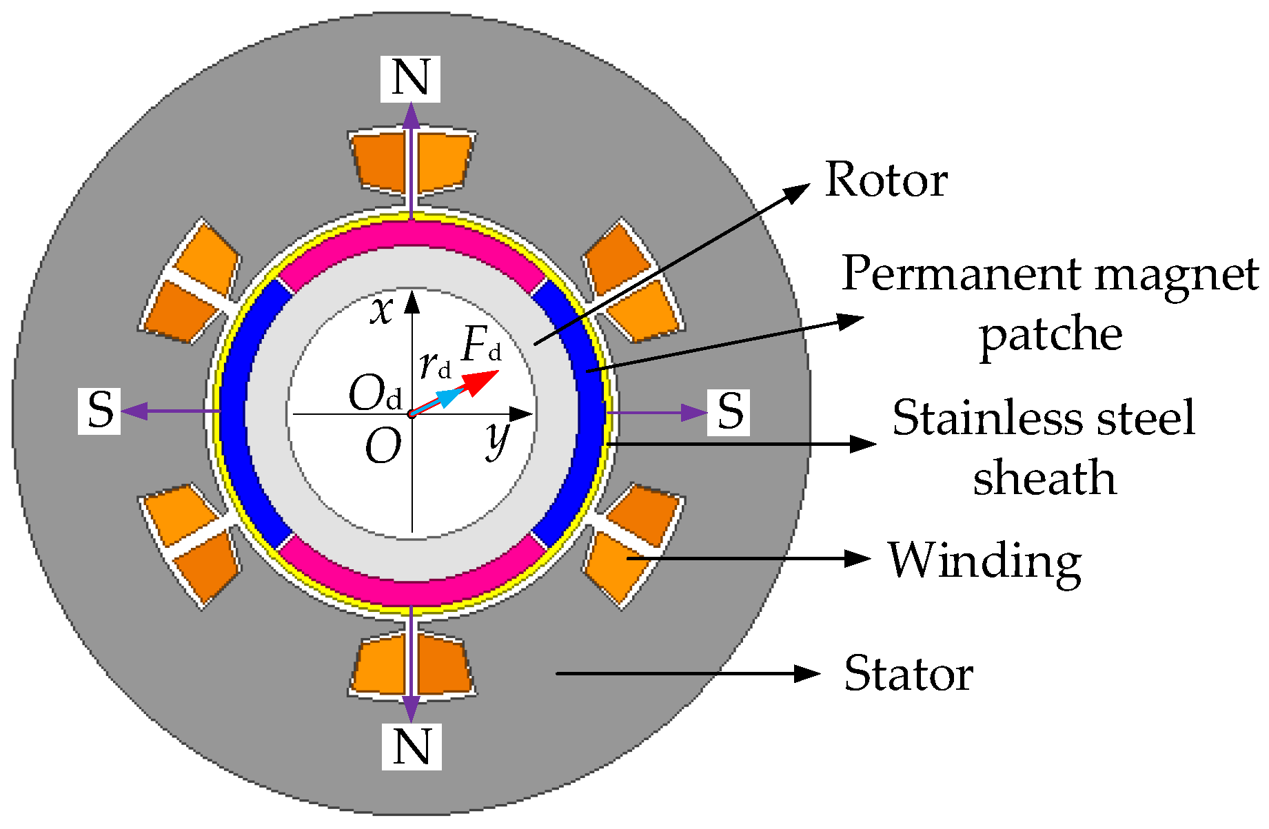
Permanent magnet synchronous motors (PMSMs) exhibit the strengths of fast response and high efficiency, and these motors are highly suitable as an energy conversion component for FESSs. Figure 1 displays the diagram of the radial cross-section structure for the PMSM studied in this work. The stator of this motor is a six-slot structure, and the stator winding adopts a three-phase winding form with a star connection. The permanent magnet rotor of this motor is composed of four-pole permanent magnet patches, and a stainless steel sheath is employed to secure the strength of the rotor structure. The permanent magnet patches are radially magnetized rubidium iron boron permanent magnets. The magnetic poles on the outer diameter surface of each permanent magnet patch are shown in Figure 1, where N represents the positive pole and S represents the negative pole. In addition, when there is a radial eccentricity rd between the rotor center Od and the stator center O, the gap width between the motor rotor and stator will exhibit an uneven distribution. A magnetic circuit is formed between the rotor and the stator of the motor, and the magnetic flux density in this circuit is related to the width of the air gap. On the side with a smaller gap width (in the positive direction of rd), the magnetic field density in the air gap is higher, which results in a greater attraction between the motor stator and the rotor; conversely, on the side with a larger gap width (in the opposite direction of rd), the attraction between the motor stator and the rotor is smaller. Therefore, when the motor rotor has an eccentricity rd, an unbalanced magnetic pull force Fd in the same direction as rd will be generated in the motor. The basic structural parameters for this motor are presented in Table 1.
Figure 1.
Planar structure diagram of this permanent magnet synchronous motor.
Table 1.
Basic structure parameters of this PMSM.
During operation of the FESS, the flywheel rotor (FR) will generate vortex due to the effect of the unbalanced mass. This causes the motor rotor integrated on the flywheel rotor to produce radial displacement, thereby generating unbalanced magnetic pull (UMP). This will directly affect the vibration characteristics of the FR. In this paper, the flywheel rotor is supported by electromagnetic bearings, which have lower support stiffness compared to rolling bearings and sliding bearings. The impact of the UMP on the vibration characteristics of the FR will be more prominent, thus it is necessary to explore the influence of this UMP in the motor on the vibration characteristics of the active magnetically suspended flywheel rotor.
This work first uses the finite element method (FEM) to analyze the variation rules of the UMP rotor eccentricity and, on this basis, establishes a dynamic model of an active magnetically levitated flywheel rotor considering the UMP. Then, the influence rules of the magnitude and position of UMP in the motor on the vibration properties of FR are analyzed.
2.2. Analysis of Unbalanced Magnetic Pull Force in the Motor Based on the Finite Element Method
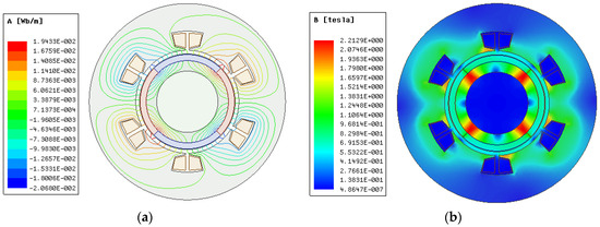
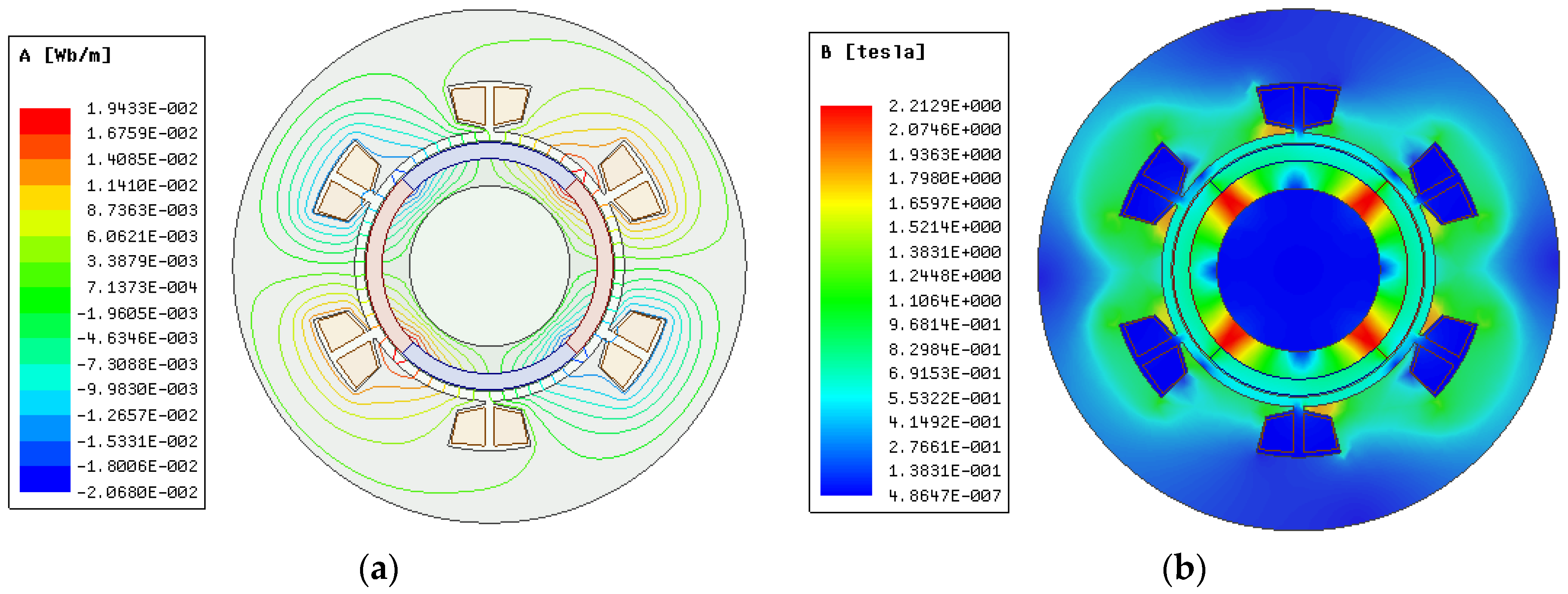
During the calculation of the magnetic field of the PMSM, it is assumed that the rotor axis of the motor is parallel to its stator axis, and the end effects are ignored. The magnetic field of the PMSM (as shown in Figure 1) is solved using the two-dimensional FEM, and the resulting magnetic field cloud map is presented in Figure 2. Figure 2a demonstrates the magnetic flux line distribution for this PMSM, from which it can be seen that no leakage phenomenon appears. Figure 2b exhibits the corresponding magnetic flux cloud map, from which it can be noticed that the maximum magnetic flux appears at the boundary between each permanent magnet on the rotor. The magnetic field distribution for this permanent magnet synchronous motor is reasonable, indicating that the structure design of this motor is reasonable.
Figure 2.
Magnetic field distribution diagram of the PMSM: (a) Magnetic field line distribution; (b) magnetic flux distribution cloud map.
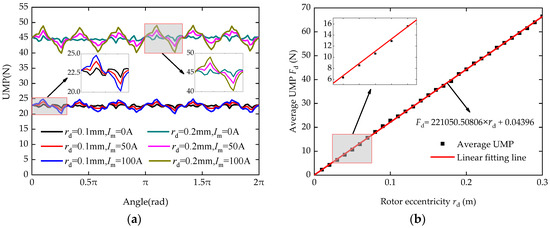
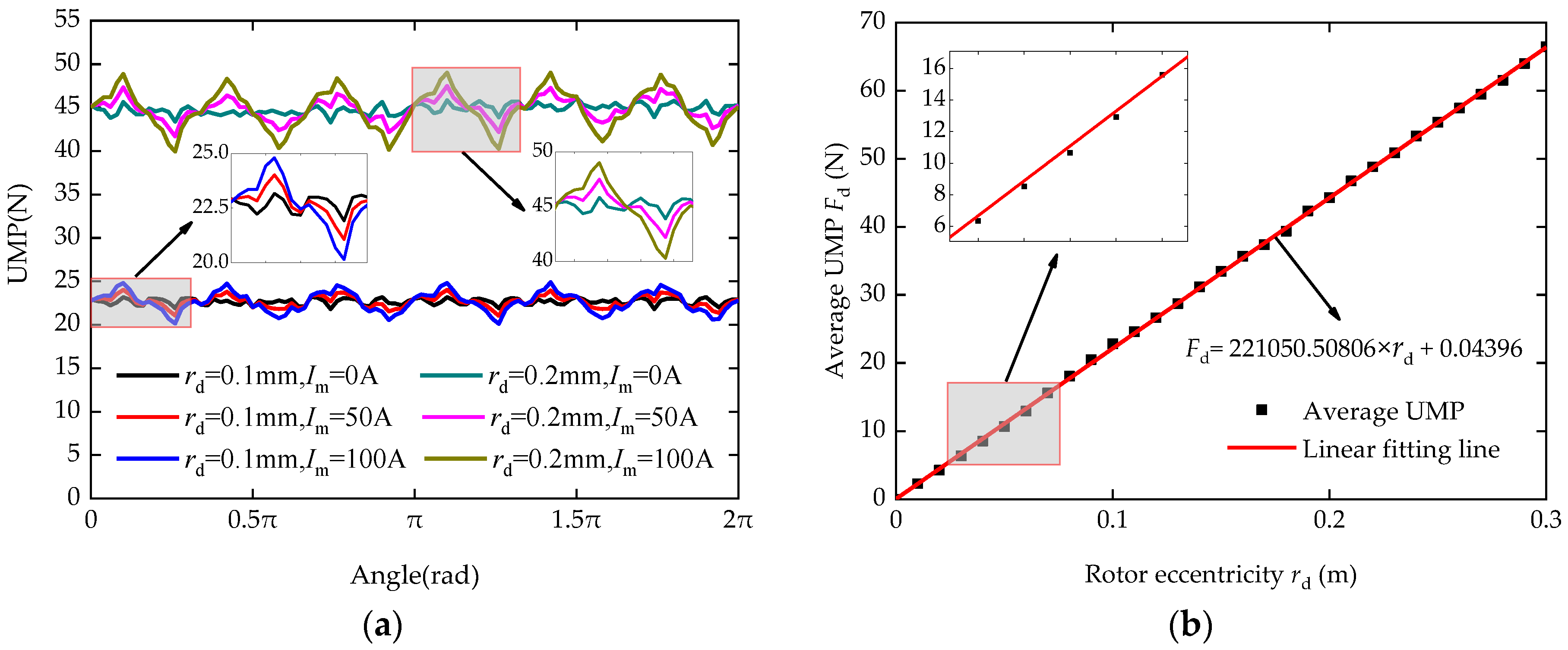
According to the radial magnetic flux density in the air gap between the rotor and stator of the motor, the radial force acting on the motor rotor, namely the unbalanced magnetic pull (UMP), can be obtained. Set the eccentricity of the motor rotor to 0.1 mm and 0.2 mm, respectively. Under these different eccentricity conditions, set the maximum amplitude of the motor winding current to 0 A, 50 A, and 100 A, respectively. Then, the variation curves of the motor UMP with the rotor rotation angle are obtained, as presented in Figure 3a.
Figure 3.
The variation curve of the UMP of motor rotor: (a) The variation in UMP with the rotation angle of the rotor; (b) the variation in UMP with rotor offset.
As can be observed in Figure 3a, when the rotor eccentricity rd is 0.1 mm and 0.2 mm, the UMP of motor fluctuates around 22.5 N and 45 N, respectively. That is, the motor UMP exhibits fluctuating changes with the increase in the rotor rotation angle. Thus, the magnitude of the UMP is mainly affected by the rotor eccentricity rd. When the winding current Im is 50 A and rd is 0.1 and 0.2 mm, respectively, the ratios of the fluctuation amplitudes of UMP to their average values both are about 5%. When Im is 100 A and rd is 0.1 and 0.2 mm, respectively, this ratio is about 10%. This means that the ratio of the fluctuation amplitude of the UMP to its average value is related to the winding current Im. The larger Im is, the higher this ratio will be. When Im is small, the discrepancy between the fluctuation amplitude of the UMP and its average value is relatively small. Therefore, when the winding current of stator is small, the average value of the motor’s UMP that varies with the rotation angle of rotor can be utilized to evaluate the unbalanced magnetic pull force in the motor. The motor studied in this work belongs to the case where the winding current is relatively small; thus, the variation in its UMP with the eccentricity of the motor rotor can be obtained, as illustrated in Figure 3b.
Usually, the unilateral air gap of the radial magnetic bearing is small; in this study, it is set at 0.3 mm. Therefore, the range of the rotor eccentricity rd is determined to be 0–0.3 mm. Figure 3b demonstrates the values of the UMP under different rd as well as the curve (red line) obtained by performing linear fitting on the values of UMP. Additionally, the linear fitting expression is given in this figure. In addition, its fitting parameter R-Square (COD) is 0.99979, which is close to 1, indicating a good linear fit. From this figure, it can be found that the UMP of motor has a linear increasing trend as the rotor eccentricity increases, which has a good consistency with the fitted straight line. Therefore, the UMP of motor can be linearized, and it can be equivalent to the product of the motor stiffness and eccentricity. Since the constant term of the fitting line expression shown in Figure 3b is very small, this constant term can be omitted.
By rounding the slope of the fitting line, the unbalanced magnetic pull force UMP of motor can be written as follows:
where kd is motor stiffness. Based on the linear fitting expression given in Figure 3b, the stiffness parameter kd of the PMSM introduced in this paper is 2.2105 × 10⁵ N/m.
The smaller the amplitude of the stator winding current is, the closer the unbalanced magnetic pull force of the motor at each rotor angle is to its average value, that is, the smaller the error between the motor stiffness and the motor UMP. Therefore, when the current of the motor stator winding is smaller, the usability of the motor stiffness obtained in this paper is better. This paper uses the motor stiffness kd to measure the magnitude of the UMP of motor and, based on this, conducts the dynamic modeling of the flywheel rotor.
3. Dynamic Model Considering the Unbalanced Magnetic Pull Force of Motor
As the rotational speed increases, the flywheel rotor (FR) will transition from a rigid mode to an elastic mode. The supporting stiffness of the magnetic levitation bearing is relatively lower compared to other types of bearings. In addition, electromagnetic bearing is suitable for achieving suspension and control of rigid rotor, and the rotational inertia and mass of the FR are both relatively large. Usually, the FR in an active magnetic levitation flywheel energy storage system is designed as a rigid rotor (that is, the FR is in a rigid mode within the design speed). Therefore, during the process of conducting dynamic modeling, the flywheel rotor is assumed to be a rigid rotor.
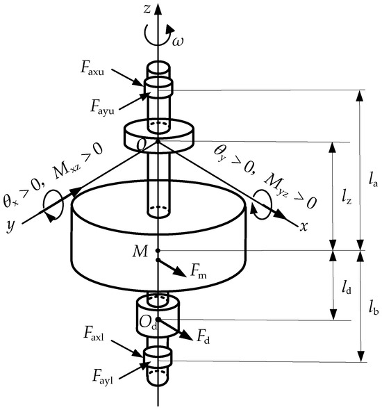
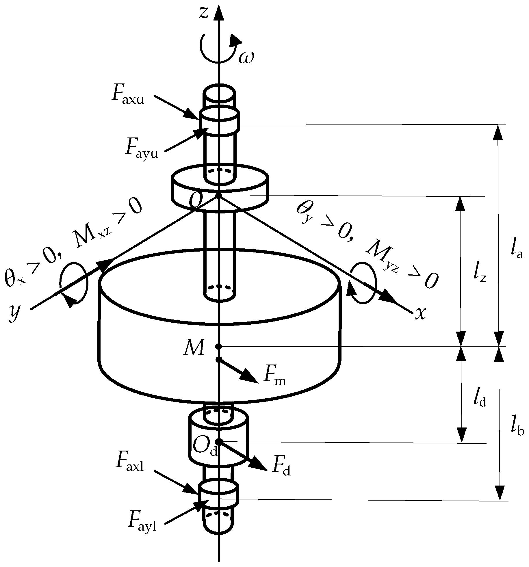
In the active magnetically levitated flywheel energy storage system, the axial movement of the FR is constrained by the axial bearing, and when the FR tilts, it will rotate around the center of the axial bearing rotor. Therefore, a fixed coordinate system O-xyz is built with the geometric center O of the axial bearing rotor under the initial equilibrium position of FR as the origin. The corresponding force analysis diagram of the FR obtained is given in Figure 4. This figure presents the force distribution of the FR and its relevant structural parameters. Here, O is the geometric center of the axial bearing rotor; M denotes the mass center of the FR without considering the unbalanced mass; Od is the geometric center of motor rotor; la and lb denote the distances for the upper and lower radial bearings relative to the FR mass center, respectively; lz and ld are the distances of the axial bearing and motor relative to FR mass center, respectively; ω denotes the angular velocity of FR (rad/s); and θx, θy and Mxz, Myz represent the rotation angle and torque of FR with respect to the y- and x-axis, respectively. Additionally, considering that the tilt rotation angle θ of FR is relatively minor in magnitude, let sinθ ≈ θ, cosθ ≈ 1.
Figure 4.
Diagram of force analysis of the flywheel rotor.
As demonstrated in Figure 4, the flywheel rotor is subjected to the support forces (Faxu, Fayu, Faxl, Fayl) from the radial magnetic bearing, the mass unbalance force Fm, the radial bearing support moments (Max, May), and the mass unbalance moments (Mmx, Mmy). In addition, the rotational vortex of the FR will cause radial movement of the center Od of motor rotor, which leads to an uneven air gap and magnetic field distribution between the stator and rotor. This causes an unbalanced radial force on the motor rotor (namely, the unbalanced magnetic pull force Fd) and unbalanced magnetic pulling force torque (Mdx, Mdy), which will directly affect the vibration characteristics of the flywheel rotor.
The supporting force Fa exerted by the radial active magnetic suspension bearing on the flywheel rotor can be expressed using equivalent dynamic stiffness ka and damping ca. Here, the parameters of ka and ca for the active magnetic suspension bearing with PID controller can be stated as follows [31]:
where ki and kx denote the stiffness coefficients of the current and displacement of the electromagnetic force, respectively; Kp, Ki, and Kd denote the proportionality coefficient, integral coefficient, and differential coefficient, respectively; Ks is displacement sensor coefficient; Ka is the power amplifier coefficient; Ts, Ta, and Td denote the time constants of the displacement sensor, power amplifier, and differential unit, respectively; and ω denotes the angular frequency of FR (rad/s).
Then, the forces exerted by the radial magnetic bearing on FR in x and y directions (Fax and Fay), as well as the moments generated by the radial magnetic bearing mounted on FR relative to the y- and x-axes (Max and May), can be stated as follows:
where xu(t) and yu(t) denote the position of the upper radial bearing rotor, which can be written as xu(t) = x(t) + (la − lz)·θx(t) and yu(t) = y(t) + (la − lz)·θy(t), respectively; xl(t) and yl(t) denote the position of the lower radial bearing rotor, which can be written as xl(t) = x(t) − (lb + lz)·θx(t) and yl(t) = y(t) − (lb + lz)·θy(t), respectively; kau and cau are the equivalent stiffness and damping of the upper radial bearing; kal and cal are the equivalent stiffness and damping of the lower radial bearing; and x(t) and y(t) denote the position of axial bearing rotor.
According to the expression of the motor unbalance magnetic pull force shown in Equation (1), the unbalanced magnetic pull (UMP) force acting on flywheel rotor in the directions of x and y (Fdx and Fdy), as well as the torque generated by the UMP on FR relative to the y- and x-axes (Mdx and Mdy), can be respectively stated as follows:
where kd represents the motor stiffness, and ld represents the distance between the motor and FR mass center.
In addition, due to the presence of the unbalanced mass on flywheel rotor, a mass imbalance force will be generated during its rotation, and the magnitude of this force varies proportionally with the square of rotating speed. The mass imbalance force (Fmx and Fmy) acting on FR along the x and y directions, as well as the torque (Mmx, Mmy) generated by this mass imbalance force around the y- and x-axes on the flywheel rotor, can be expressed as follows:
where Um represents the mass imbalance quantity; lm denotes the axial spacing between the unbalanced mass and FR mass center M; and α0, ω0, and a are the initial rotation angle, initial angular velocity, and angular acceleration of the FR, respectively.
Based on Newtonian vector mechanics and the theorem of angular momentum and by combining Equations (2)–(5), the dynamic mathematical model of the active magnetic levitation rigid flywheel rotor considering the unbalanced magnetic pull (UMP) of the motor can be acquired as follows:
where ; ; ;
; ; ;
; and .
Furthermore, Jd is the equatorial moment of inertia of the flywheel rotor, and Jp is the polar moment of inertia of the flywheel rotor.
The dynamic model as shown in Equation (6) is appropriate for solving the vibration characteristic parameters of the FR under the rigid body mode. This paper utilizes this dynamic model to analyze the influence rule of the UMP on the vibration characteristics of the active magnetic levitation rigid flywheel rotor.
4. The Influence of Unbalanced Magnetic Pull Force of Motor on the Dynamic Characteristics of Active Magnetic Suspension Flywheel Rotor
The magnitude of the motor unbalanced magnetic pull (UMP) and its acting location will affect the force state of the flywheel rotor (FR), thereby altering the vibration properties of the active magnetically levitated flywheel rotor. The critical speed and mass imbalance response are important manifestations of the vibration characteristics of flywheel rotor. Therefore, this section explores the effect of the magnitude of motor UMP and its acting location on the critical speed and mass imbalance response of FR employing the numerical computation method.
4.1. Numerical Solution and Analysis of the Vibration Characteristic Parameters of FR
The structural and physical parameters for the FR are presented in Table 2. Additionally, the parameters for radial active magnetic bearing are listed in Table 3. Substitute these parameters into the dynamics model as shown in Equation (6), and solve this model using the fourth-order Runge–Kutta numerical method. Here, the motor stiffness kd represents the magnitude of the UMP in motor, and the motor position ld (namely, the axial distance between the motor and FR mass center) represents the location where the UMP acts. By adjusting the parameters of kd and ld, the variation curve of the vibration amplitude of FR with speed can be obtained based on different UMP values and their acting positions. Here, the initial angular velocity ω0 = 0.1 rad/s and angular acceleration a = 3 rad/s2 are determined in the solving process.
Table 2.
Structural and physical parameters of FR.
Table 3.
Parameters of the radial active magnetic bearing.
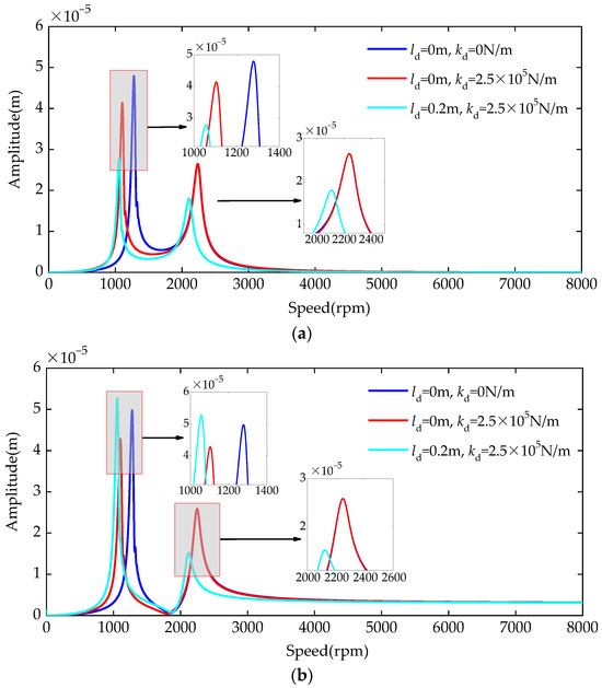
When the stiffness kd of the motor and its position ld are 0 N/m and 0 m, 2.5 × 10⁵ N/m and 0 m, and 2.5 × 10⁵ N/m and 0.2 m, separately, the obtained curves of the FR’s vibration amplitude versus the speed at the radial bearing positions are presented in Figure 5a,b. Figure 5a exhibits the amplitude curves of the FR at the position of its upper radial bearing, and Figure 5b demonstrates the amplitude curves at the lower radial bearing position.
Figure 5.
Under different motor stiffness kd and position ld, the variation curves of the flywheel rotor’s vibration amplitude versus speed at the positions of radial bearing are presented: (a) Amplitude curves under the upper radial bearing position; (b) amplitude curves under the lower radial bearing position.
From Figure 5a,b, it can be found that as the speed increases, there are two peaks in the amplitude curves of FR under its upper and lower radial bearing positions. The speeds at these two peak points stand for the first- and second-order critical speeds ω1c and ω2c of FR. As the motor is placed at the FR mass center (namely, ld = 0 m), compared with the case where kd = 0 N/m, when the motor stiffness kd is 2.5 × 10⁵ N/m, the ω1c significantly decreases, and the vibration amplitude of FR at its radial bearing position significantly decreases under ω1c. However, there is no significant change in ω2c and its vibration amplitude under this speed. This indicates that the existence of motor stiffness (that is, the UMP in motor) has an obvious impact on the first critical speed ω1c and that the vibration amplitude corresponds to this speed.
In addition, under the condition that the motor stiffness kd is 2.5 × 10⁵ N/m, compared to ld = 0, when the motor position ld is 0.2 m, the ω1c and ω2c of FR both decrease, and ω2c exhibits a more obvious decreasing trend. Furthermore, below the first critical speed ω1c, the corresponding vibration amplitude at the upper radial bearing significantly decreases, while that at the lower radial bearing significantly increases. Below the ω2c, the vibration amplitudes of FR at the upper and lower radial bearings both obviously decrease. This demonstrates that the motor position ld, which is the location where the UMP acts, has an obvious effect on critical speed of the FR and its vibration amplitude.
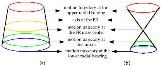
In addition, based on the displacement parameters (x, y) and tilt angle parameters (θx, θy) of the FR, the vibration modes (namely, the motion trajectory of the axis of FR) of the active magnetically levitated flywheel rotor at its first- and second-order critical speeds ω1c and ω2c can be obtained, as shown in Figure 6a,b. In this figure, the black straight line represents the axis of the FR, the red curve shows the motion trajectory of the FR at its upper radial bearing, the yellow curve denotes the motion trajectory at the mass center of FR, the green curve indicates the motion trajectory of FR at the position of motor, and the blue curve represents the motion trajectory of FR at its lower radial bearing.
Figure 6.
The vibration mode of FR: (a) Vibration mode at the first-order critical speed; (b) vibration mode at the second-order critical speed.
As indicated in Figure 6a, the FR exhibits a translational vibration mode below the critical speed ω1c. Under this vibration mode, the critical speed of FR is closely related to the radial support force. However, the existence of motor UMP (namely, the motor stiffness kd) will directly change the radial support force of the FR, thereby exerting a significant influence on ω1c. In addition, Figure 6b shows that the FR presents a conical vibration mode at the critical speed ω2c. Below this vibration mode, the critical speed of the FR is closely related to the supporting moment, while the changes of the UMP in motor and its acting position will directly affect the supporting moment on the flywheel rotor, thereby significantly influencing ω2c.
In addition, under the translational vibration mode (this corresponds to the first-order critical speed), the variation in the magnitude of UMP and its acting location will alter the radial displacement and tilt angle of the FR; as these two factors increase, the vibration amplitudes at the positions of the upper and lower radial bearings exhibit the same or opposite tendencies. Under the conical vibration mode (this corresponds to the second-order critical speed), the change in the UMP will alter the inclination angle of the FR. At this time, as the inclination angle increases, the vibration amplitudes at the positions of the upper and lower radial bearings present the same trends.
4.2. The Influence of Motor Unbalanced Magnetic Pull Force on the Critical Rotation Speed of the Active Magnetic Suspension Flywheel Rotor
From the above analysis in Section 4.1, it can be concluded that the presence of the motor UMP will affect the vibration characteristics of the active magnetic suspension flywheel rotor. Critical speed is one of the significant features of rotor vibration. Hence, this section primarily explores the influence rules of the magnitude of motor UMP (characterized by motor stiffness kd) and its acting position (characterized by motor position ld) on the first- and second-order critical speeds (ω1c and ω2c) of the active magnetic suspension flywheel rotor.
In order to quantify the position of the motor on the flywheel rotor shaft system, the parameter of the motor position offset ratio β is defined. Its definition is as follows:
where ld represents the distance between the motor and the mass center of FR, and lb is the distance from the lower radial bearing to the mass center of FR. For the flywheel energy storage system studied in this paper, the motor is located between the mass center of FR and the lower radial bearing. The range of parameter β is between 0 and 1, and the larger the β is, the greater the distance from the motor to the mass center of FR.
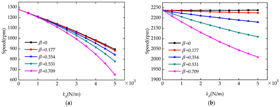
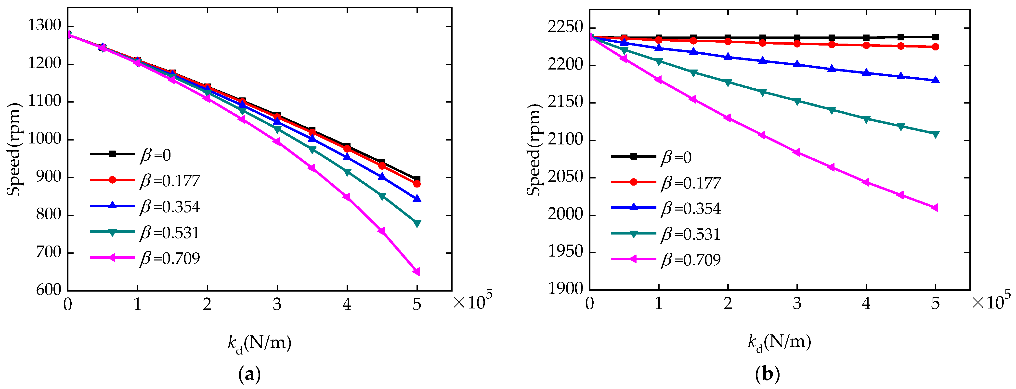
Under different motor position offset ratios β, the curves showing the variation in critical speed as motor stiffness kd are presented in Figure 7. Here, Figure 7a,b demonstrate the curves of critical speeds ω1c and ω2c versus kd when the β is 0, 0.177, 0.355, 0.532, and 0.709.
Figure 7.
Curves of the critical speed of FR with kd and β: (a) Variation curves of the first-order critical speed; (b) variation curves of the second-order critical speed.
As presented in Figure 7a, the changes in motor stiffness kd and its position offset ratio β both have an obvious effect on the critical speed ω1c of FR. With the increase in kd and β, the ω1c presents a declining tendency. It indicates that the rise of the UMP reduces the first critical speed of FR. In addition, as the axial distance ld from the position of motor to the FR’s mass center increases, the ω1c also decreases. This is mainly because the direction of the UMP is opposite to that of the radial bearing support force. Specifically, compared to the stiffness of the radial bearing, the motor stiffness is a negative stiffness. The radial support stiffness of the FR will decrease as the motor stiffness increases. Moreover, at the critical speed ω1c, the FR exhibits a translational mode (as shown in Figure 6a), and the critical speed under this vibration mode decreases with the decrease in its radial support stiffness. Thus, as the magnitude of the UMP increases, the first critical speed presents a decreasing trend. In addition, as the axial distance from the motor position and the FR mass center increases, the UMP torque acting on the FR increases, which leads to an increase in the inclined rotation angle of the FR. Due to the coupling between the radial motion and inclined rotation of the FR, ω1c demonstrates a decreasing trend with the increase in ld. In the case where β is 0, 0.355, and 0.709 and when kd = 2.5 × 10⁵ N/m, the reduction in ω1c is 13.7%, 14.6%, and 17.5%, respectively; when kd = 5 × 10⁵ N/m, ω1c decreases by 30%, 34%, and 49%, respectively. From this, it can be seen that the influence of motor stiffness kd on the critical speed ω1c is greater than that of the motor position offset ratio β on ω1c.
Figure 7b shows that the changes in the motor stiffness kd and its position offset ratio β both have a significant effect on the second critical speed ω2c. When β = 0, the variation in kd has no clear influence on ω2c. However, when β ≠ 0, ω2c decreases as both kd and β increase. This indicates that when the axial spacing ld is 0, the increase in the motor’s UMP produces no distinct impact on the second critical speed; however, as ld and UMP increase, the ω2c decreases. This is because the FR exhibits a conical vibration mode under the ω2c, as shown in Figure 6b. In this mode, the critical speed for FR primarily depends on its supporting moment. When the axial spacing ld is 0, the variation in the UMP shows no significant impact on the supporting moment. However, this supporting moment decreases as ld and UMP increase. This results in a reduction in the ω2c. When kd = 2.5 × 10⁵ N/m and β is 0.355 and 0.709, the corresponding critical speed ω2c declines by 1.4% and 5.9%, respectively; furthermore, when kd = 5 × 10⁵ N/m, and β is 0.355 and 0.709, ω2c decreases by 2.6% and 10%, respectively. Thus, it can be seen that the effect of the motor stiffness kd on the second critical speed ω2c is smaller than that of the motor position offset ratio β on ω2c.
From the above analysis, it can be concluded that the UMP in the motor and its acting position will significantly reduce the critical speed of the FR. In addition, the variation in the UMP exerts a more prominent impact on the first critical speed, while the change in its acting position produces a more distinct influence on the second critical speed. Therefore, during the process of an active magnetically levitated flywheel energy storage system design, in order to accurately determine the critical speed of the FR and its operating speed range, the effect of the UMP on the critical speed should be taken into account.
4.3. The Influence Rule of the Unbalanced Magnetic Pull Force of the Motor on the Mass Imbalance Response of the Active Magnetic Levitation Flywheel Rotor
The mass imbalance response is a vital manifestation of the operational stability of the flywheel rotor (FR), while the existence of the motor’s UMP will change the force state of the FR, thereby affecting the mass imbalance response. As shown in the vibration amplitude curves illustrated in Figure 5 of Section 4.1, the presence of the UMP produces a significant effect on the vibration amplitude under critical speed. However, after the second critical speed, this vibration amplitude does not change significantly with the alteration in the motor stiffness kd and the motor position ld. Therefore, this part mainly discusses the change rules of the mass imbalance response for the FR under critical speed along with the variation in the UMP. Here, the motor position offset ratio β is adopted to quantify the axial position of this motor mounted on the FR, and β = ld/lb.
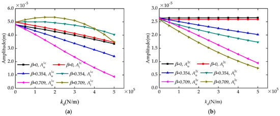
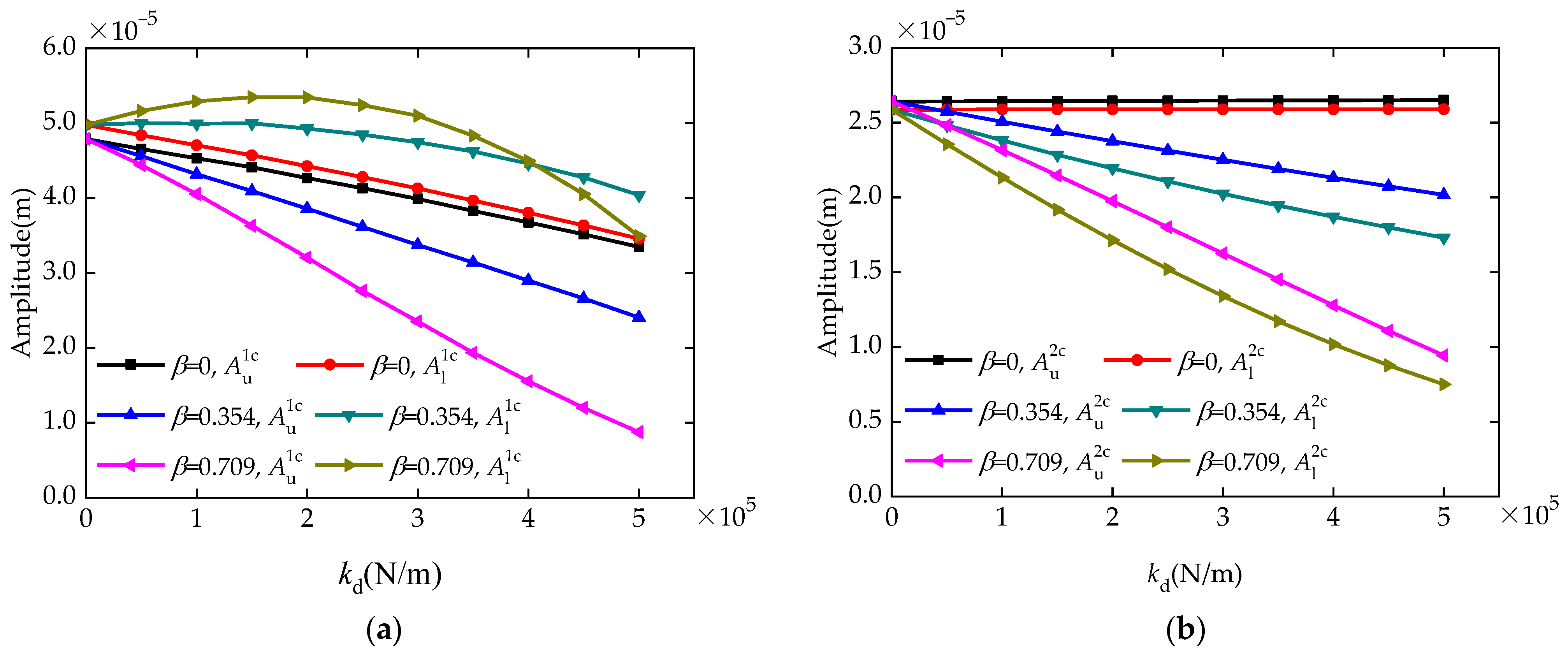
Under different β values at critical speeds, the calculated curves for vibration amplitude of FR at positions of its radial bearings versus kd are presented in Figure 8a,b. Among them, under the critical speed ω1c, when β is 0, 0.354, and 0.709, separately, the curves for the vibration amplitude (, ) at the upper and lower radial bearing positions versus kd are displayed in Figure 8a; meanwhile, under the critical speed ω2c, the corresponding curves for vibration amplitude (, ) are presented in Figure 8b.
Figure 8.
Under the critical speed, the FR’s vibration amplitude curves at the positions of its upper and lower radial bearings along with kd and β: (a) Amplitude curves below the ω1c; (b) amplitude curves below the ω2c.
Figure 8a reveals that the variations in motor stiffness kd and its position offset ratio β both have a significant impact on the vibration amplitude for FR at the positions of its radial bearing below the first critical speed ω1c. The vibration amplitude for FR at its upper radial bearing position decreases as kd and β increase. However, the trend of its vibration amplitude at the lower radial bearing position with kd is related to β. As β increases, the variation trend in with kd changes from gradually decreasing to first increasing and then decreasing. This indicates that as the UMP and the axial distance ld increase, the vibration amplitude at its upper radial bearing position decreases; however, its vibration amplitude at the lower radial bearing position shows different variation trends with the increase in ld as the UMP changes. When ld is small, the amplitude maintains a decreasing trend. However, as ld increases, this evolves into a trend of first increasing and then decreasing. This is mainly because as the UMP and its axial distance ld increase, the ω1c decreases. This will lead to a significant reduction in its mass imbalance force at the speed of ω1c, thereby causing a decrease in the vibration amplitude ( and ) under the position of the radial bearings. However, the increase in UMP and ld will lead to a reduction in the radial support force imposed on FR, which will cause an increase in and . Additionally, the variation in the motor position will affect the support torque of FR. This will change the tilt angle of the FR; thus, the variation in the vibration amplitude at the upper and lower radial bearing positions exhibits different trends. The variation pattern of the vibration amplitude at the position of radial bearings is a manifestation under the combined effects of various factors. Among them, in the case where β is 0, 0.355, and 0.709 and when kd = 2.5 × 10⁵ N/m, decreases by 13.7%, 24.5%, and 33.1% respectively, and shows decreases of 14% and 2.6% as well as an increase of 7.4%, respectively. When kd = 5 × 10⁵ N/m, decreases by 30.1%, 49.8%, and 82%, respectively, and the corresponding presents a decrease of 30.4%, 18.8%, and 29.9%, respectively. From this, it can be seen that both the motor stiffness kd and its position offset ratio β have a distinct effect on the vibration amplitudes and .
In addition, as presented in Figure 8b, when β = 0, the change in motor stiffness kd has no clear effect on the vibration amplitudes ( and ) under the position of the upper and lower radial bearings below the critical speed ω2c. However, when β ≠ 0, both and decrease with the increase in kd and β, and their decreasing trends become more obvious as β increases. This means that when the axial spacing ld is 0, the increase in the motor’s UMP has no significant effect on the vibration amplitudes ( and ) at the radial bearing positions below the speed of ω2c; however, both and decrease with the increase in ld and UMP. This is noted because when ld is 0, the change in UMP has no obvious effect on the supporting moment of FR and its second critical speed ω2c. However, as UMP and ld increase, the ω2c of the FR declines, causing a reduction in the mass imbalance moment acting on the FR under the speed ω2c. This leads to a decrease in the vibration amplitude at the position of the radial bearings under the speed ω2c. Although as the UMP and ld increase, the supporting moment of the FR decreases, which will lead to a rise in FR vibration amplitude. The reduction in vibration amplitude caused by the decrease in the mass unbalance moment at the speed ω2c is more significant. Therefore, below the critical speed ω2c, the vibration amplitudes of FR under its upper and lower radial bearing positions exhibit a decreasing trend. In the case where β is 0.355 and 0.709 and when kd = 2.5 × 10⁵ N/m, decreases by 12.4% and 25.2%, respectively, and decreases by 18.6% and 33.8%, respectively. When kd = 5 × 10⁵ N/m, decreases by 23.6% and 64.3%, respectively, and decreases by 33.1% and 71%, respectively. Thus, it can be seen that both the kd and β produce an obvious effect on the vibration amplitudes and , and the impact of these two factors on vibration amplitude at the lower radial bearing position is greater than that at the upper radial bearing position.
The above analysis reveals that the magnitude of the UMP and its acting location produce a significant impact on the vibration amplitude induced by the mass imbalance response of the FR under the critical speed. Reasonable motor parameter design can reduce the vibration amplitude of FR under its radial bearing positions at the critical speed, which helps the flywheel rotor to stably cross the critical speed range. However, the existence of UMP in the motor will reduce the overall support stiffness of the FR. When the flywheel energy storage system is subjected to external excitation, the running reliability of the active magnetically levitated flywheel rotor will be affected to some extent. Therefore, in the process of investigating the operational stability of the active magnetically levitated flywheel rotor under external excitation, the influence of the UMP in the motor should be considered.
5. Experiment
5.1. Experimental Setup
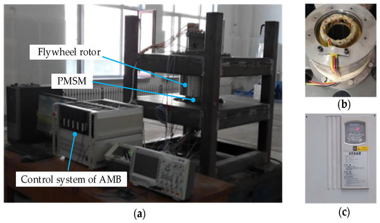
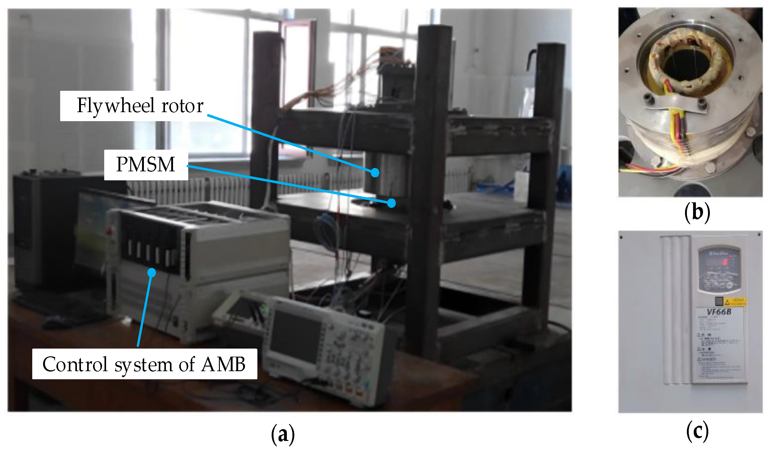
The experimental testing platform and its components are given in Figure 9. Figure 9a demonstrates the prototype of the active magnetically levitated flywheel energy storage system. The stator and controller of motor in this prototype are respectively shown in Figure 9b,c. The flywheel rotor adopts a vertical support structure, and both its radial and axial supports are equipped with active magnetic suspension bearings. Among them, the motor is the permanent magnet synchronous motor (PMSM) studied in this work, and it is driven and controlled by a frequency converter. This motor is located between the flywheel and the lower radial electromagnetic bearing, and the distance ld between it and the mass center of FR is 0.111 m.
Figure 9.
Experimental test platform: (a) Prototype of vertical active magnetically levitated flywheel energy storage system; (b) motor stator; (c) motor controller.
During the experimental testing process, the voltage signals from the eddy current displacement sensor of the radial active magnetically levitated bearing are collected using the PXI data acquisition system (sampling frequency is 3000 Hz). Converting the gathered signals based on the transformation relation between the voltage and displacement of the displacement sensor, the vibration amplitude signals of FR under the position of its radial bearings can be acquired. By conducting frequency domain analysis on these vibration signals, the vibration amplitude of FR at different speeds can be obtained; thus, the corresponding experimental vibration amplitude curve of the FR can be obtained.
5.2. Analysis of Theoretical and Experimental Test Results
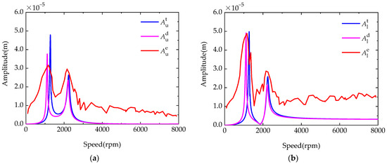
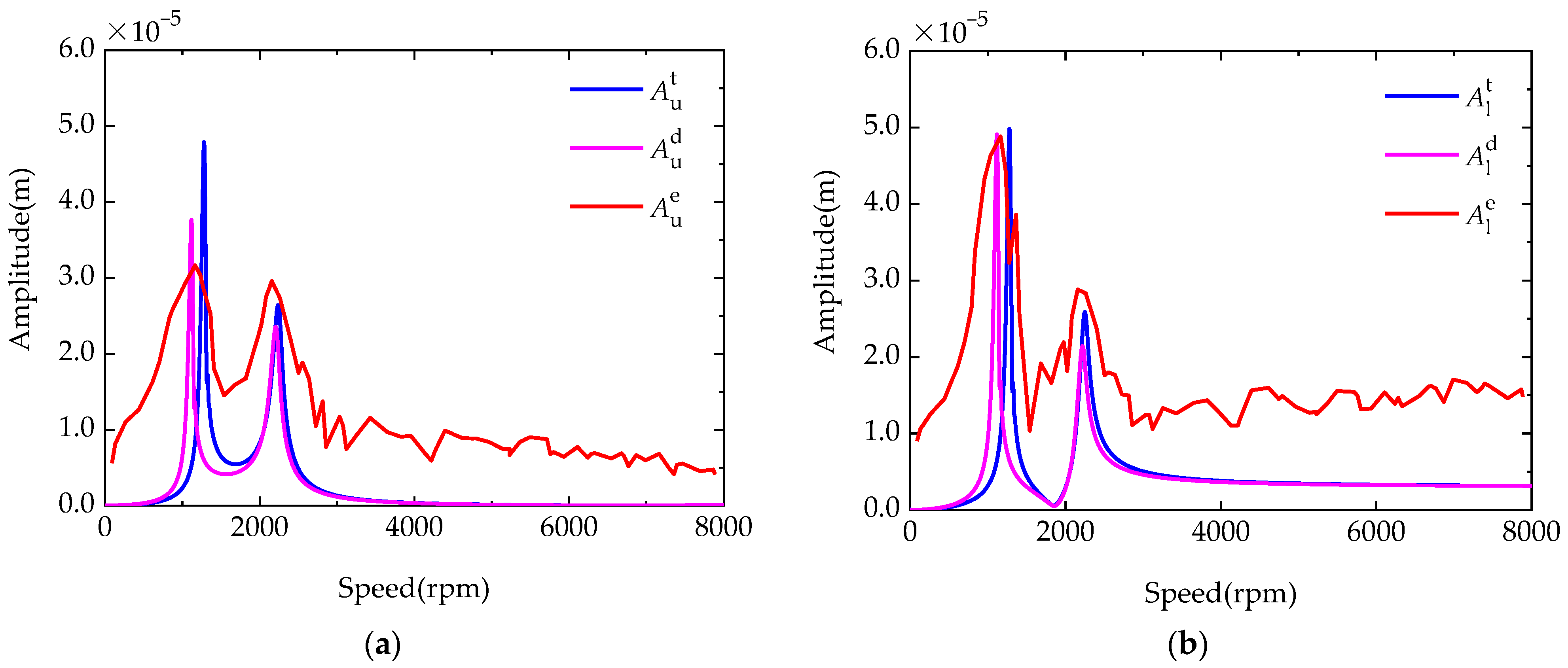
The vibration amplitudes (, ) of FR under the position of its upper and lower radial bearings obtained from the experimental tests are shown in Figure 10 as the red curve. The theoretical calculation results of the amplitude values (, ) of FR without considering the UMP are shown in Figure 10 as the blue curve. Moreover, when considering the UMP in the motor, the corresponding theoretical results for the amplitudes (, ) of FR under its upper and lower radial bearing positions are exhibited in Figure 10 as the pink curve.
Figure 10.
Theoretical calculation and experimental test results of the FR vibration amplitude under the position of its radial bearings: (a) Vibration amplitude at the position of the upper bearing; (b) vibration amplitude at the position of the lower bearing.
Figure 10 shows that the experimental as well as theoretical calculation vibration amplitude curves for FR under its radial bearing positions have a certain deviation in numerical values, but their overall trend of change has a good consistency. Among them, the measured results for the FR’s first- and second-order critical rotational speeds are 1165 and 2155 rpm, respectively. When the UMP is not considered, the corresponding theoretical results are 1278 and 2238 rpm, respectively. These values are slightly larger than the experimental ones, and the relative deviations among them and the testing results are 9.7% and 3.8%, respectively. When considering the UMP of the motor, the corresponding theoretical results are 1115 and 2202 rpm, respectively, and the relative errors between them and the experimental results are 4.3% and 2.2%, respectively. In addition, in theoretical calculations, when considering the UMP, the first-order critical speed decreased by 163 rpm, while the second-order critical speed decreased by 36 rpm, indicating a significant difference in the changes between these two critical speeds. This is mainly because the factors affecting the first and second critical speeds are different. Among them, the first critical speed is closely related to the mass of the FR and its radial support force, while the second critical speed is related to its equatorial moment of inertia and support torque.
From this, it can be evident that when considering the UMP in the motor, the relative error among their calculated and tested results is smaller. Furthermore, when taking into account the UMP, the calculated vibration amplitudes are more closer to their experimental results. This verifies the correctness of the theoretical model established in this paper and the validity of the conclusions obtained from this investigation. In addition, there are some deviations between the theoretical model and the experimental system that ignore the three-dimensional effects of the magnetic field in motor and the stiffness of the foundation frame. This will lead to some errors, and in future research, the theoretical model can be further improved to reduce errors.
6. Conclusions
This paper primarily investigated the influence of the motor UMP on the vibration characteristics of the FR in an active magnetically suspended flywheel energy storage system. The variation rules for the UMP caused by rotor eccentricity in a permanent magnet synchronous motor (PMSM) adapted to FESS were analyzed using the finite element method. On this basis, a dynamic model of the magnetically suspended rigid flywheel rotor taking into account the UMP was constructed, and the impact of the magnitude of this motor UMP and its acting location on the vibration properties of FR was explored. Furthermore, the correctness of the theoretical results was verified using experiments. The conclusions obtained from this investigation were as follows:
- The unbalanced magnetic pull (UMP) in the PMSM increased as the rotor eccentricity increased. The magnitude of this UMP fluctuated with the increase in the rotor rotation angle; however, this fluctuation amplitude was relatively small compared to the value of the motor UMP. Overall, the UMP presented a linear increase trend with the increase in rotor eccentricity.
- The first- and second-order critical rotational speeds of the active magnetic suspension flywheel rotor both decreased as the motor UMP and its axial position offset ratio β increased. When the motor stiffness kd was 2.5 × 10⁵ N/m and the offset ratios β were 0.354 and 0.709, the first critical speed decreased by 14.6% and 17.5%, respectively, and the second critical speed decreased by 1.4% and 4.8%, respectively. Moreover, the size of the motor UMP and its acting location also had a significant effect on the vibration amplitude induced by the mass imbalance response of the FR.
- When considering the UMP in the motor, the calculated results for the vibration characteristics of the active magnetic suspension flywheel rotor were more similar to the measured ones, which validated the correctness of the established theoretical model and the conclusions obtained in this paper. During the analysis of the rotor vibration characteristics of an active magnetically suspended flywheel energy storage system, the impact of the motor UMP should be taken into account.
Author Contributions
Conceptualization, L.W.; methodology, L.W.; software, L.W.; validation, L.W., T.L. and Z.R.; investigation, L.W.; resources, T.L. and Z.R.; data curation, L.W.; writing—original draft preparation, L.W.; writing—review and editing, L.W.; visualization, L.W.; supervision, T.L. and Z.R. All authors have read and agreed to the published version of the manuscript.
Funding
This work is supported by the National High-tech Research and Development Program of China (Grant No. 2013AA050802) and the Fundamental Research Special Funds for the Central Universities of Harbin Engineering University (Grant No. HEUCFZ1024).
Institutional Review Board Statement
Not applicable.
Informed Consent Statement
Not applicable.
Data Availability Statement
The original contributions presented in this study are included in the article. Further inquiries can be directed to the corresponding author.
Conflicts of Interest
The authors declare no conflicts of interest.
References
- Mahmoud, M.; Ramadan, M.; Olabi, A.G.; Pullen, K.; Naher, S. A review of mechanical energy storage systems combined with wind and solar applications. Energy Convers. Manag. 2020, 210, 112670. [Google Scholar] [CrossRef] [Scilit]
- Qi, Z.N.; Zhang, Y.; Yu, S.Y.; Fu, Z.J. Design and Analysis of the Multilayer Sleeve Structure for the Rotor Eddy Current Loss Reduction of a High-Speed Permanent Magnet Motor for Flywheel Energy Storage System. IEEE Trans. Transp. Electrif. 2025, 11, 11398–11409. [Google Scholar] [CrossRef] [Scilit]
- Tziovani, L.; Hadjidemetriou, L.; Charalampous, C.; Tziakouri, M.; Timotheou, S.; Kyriakides, E. Energy Management and Control of a Flywheel Storage System for Peak Shaving Applications. IEEE Trans. Smart Grid 2021, 12, 4195–4207. [Google Scholar] [CrossRef] [Scilit]
- Soomro, A.; Amiryar, M.E.; Pullen, K.R.; Nankoo, D. Comparison of Performance and Controlling Schemes of Synchronous and Induction Machines Used in Flywheel Energy Storage Systems. In Proceedings of the 3rd Annual Conference in Energy Storage and Its Applications (3rd CDT-ESA-AC), Sheffield, UK, 11–12 September 2018. [Google Scholar]
- Yan, Z.G.; Wu, S.P.; Huang, M.P.; Zhang, W.; Zhang, M.; Zhang, P.L. A Stator-PM Counter-Rotating Dual-Rotor High-Speed Electrical Machine for Flywheel Energy Storage System. IEEE Trans. Ind. Electron. 2025, 73, 4506–4517. [Google Scholar]
- Hüner, E. A New Multi-Axial Flux Pm Motor-Generator System for Flywheel Energy Storage. Appl. Sci. 2025, 15, 2524. [Google Scholar] [CrossRef] [Scilit]
- Ye, C.Y.; Yu, D.Z.; Liu, K.F.; Dai, Y.Z.H.; Deng, C.; Yang, J.T.; Zhang, J.P. Research of a Stator PM Excitation Solid Rotor Machine for Flywheel Energy Storage System. IEEE Trans. Ind. Electron. 2022, 69, 12140–12151. [Google Scholar] [CrossRef] [Scilit]
- Zhou, Y.; Bao, X.H.; Di, C.; Wang, L. Analysis of dynamic unbalanced magnetic pull in induction motor with dynamic eccentricity during starting period. IEEE Trans. Magn. 2016, 52, 8202604. [Google Scholar] [CrossRef] [Scilit]
- Zhang, A.; Bai, Y.; Yang, B.; Li, H. Analysis of Nonlinear Vibration in Permanent Magnet Synchronous Motors under Unbalanced Magnetic Pull. Appl. Sci. 2018, 8, 113. [Google Scholar] [CrossRef] [Scilit]
- Gruber, W.; Hinterdorfer, T.; Sima, H.; Schulz, A.; Wassermann, J. Comparison of different motor-generator sets for long term storage flywheels. In Proceedings of the IEEE International Symposium on Power Electronics, Electrical Drives, Automation and Motion (SPEEDAM), Ischia, Italy, 18–20 June 2014. [Google Scholar]
- Sun, X.D.; Su, B.K.; Wang, S.H.; Yang, Z.B.; Lei, G.; Zhu, J.G.; Guo, Y.G. Performance Analysis of Suspension Force and Torque in an IBPMSM with V-Shaped PMs for Flywheel Batteries. IEEE Trans. Magn. 2018, 54, 8105504. [Google Scholar] [CrossRef] [Scilit]
- Liu, K.; Yin, M.; Hua, W.; Ma, Z.Q.; Lin, M.Y.; Kong, Y. Design and Optimization of an External Rotor Ironless BLDCM Used in a Flywheel Energy Storage System. IEEE Trans. Magn. 2018, 54, 8109105. [Google Scholar] [CrossRef] [Scilit]
- Sun, M.X.; Xu, Y.L.; Han, K. Structure and Optimization Design of Cup Winding Permanent Magnet Synchronous Machine in Flywheel Energy Storage System. IEEE Trans. Magn. 2023, 59, 8100805. [Google Scholar] [CrossRef] [Scilit]
- Sun, M.X.; Xu, Y.L.; Zhang, W.J. Multiphysics Analysis of Flywheel Energy Storage System Based on Cup Winding Permanent Magnet Synchronous Machine. IEEE Trans. Energy Convers. 2023, 38, 2684–2694. [Google Scholar] [CrossRef] [Scilit]
- Sun, M.X.; Xu, Y.L.; Li, G.S. Analysis of No-Load Operation of Cup Winding Permanent Magnet Synchronous Machine in Flywheel Energy Storage Application. IEEE/ASME Trans. Mechatron. 2024, 29, 3739–3749. [Google Scholar] [CrossRef] [Scilit]
- Wang, G.J.; Wang, P.; Wang, X.Y. Equivalent Magnetic Circuit Reluctance Optimization for Rotor Loss Reduction in Permanent Magnet Synchronous Motor for UPS-FESS. IEEE Access 2020, 8, 107593–107600. [Google Scholar] [CrossRef] [Scilit]
- Chen, Y.G.; Zang, B.Q.; Wang, H.T.; Liu, H.X.; Li, H.R. Research on Composite Rotor of 200kW Flywheel Energy Storage System High Speed Permanent Magnet Synchronous Motor for UPS. In Proceedings of the 24th International Conference on Electrical Machines and Systems (ICEMS), Gyeongju, Republic of Korea, 31 October–3 November 2021. [Google Scholar]
- Li, Y.W.; Zhu, C.S.; Wu, L.J.; Zheng, Y.T. Multi-Objective Optimal Design of High-Speed Surface-Mounted Permanent Magnet Synchronous Motor for Magnetically Levitated Flywheel Energy Storage System. IEEE Trans. Magn. 2019, 55, 8202708. [Google Scholar] [CrossRef] [Scilit]
- Jiang, X.J.; Zhang, L.; Li, F.W.; Zhao, Z.H. Design and Analysis of a Highly Reliable Permanent Magnet Synchronous Machine for Flywheel Energy Storage. Machines 2024, 12, 655. [Google Scholar] [CrossRef] [Scilit]
- Dagnaes-Hansen, N.A.; Santos, I.F. Magnetically suspended flywheel in gimbal mount-Nonlinear modelling and simulation. J. Sound Vib. 2018, 432, 327–350. [Google Scholar] [CrossRef] [Scilit]
- Yang, Y.; Liu, C.N.; Chen, L.; Zhang, X.L. Phase deviation of semi-active suspension control and its compensation with inertial suspension. Acta Mech. Sin. 2024, 40, 523367. [Google Scholar] [CrossRef] [Scilit]
- Li, J.T.; Liu, Z.J.; Nay, L.H.A. Effect of Radial Magnetic Forces in Permanent Magnet Motors With Rotor Eccentricity. IEEE Trans. Magn. 2007, 43, 2525–2527. [Google Scholar] [CrossRef] [Scilit]
- Song, Y.X.; Liu, Z.Y.; Hou, R.J.; Gao, H.J.; Huang, B.; Wu, D.Z.; Liu, J.T. Research on electromagnetic and vibration characteristics of dynamic eccentric PMSM based on signal demodulation. J. Sound Vib. 2022, 541, 117320. [Google Scholar] [CrossRef] [Scilit]
- Zhang, H.S.; Liu, Y.B.; Teng, W.; Song, S.Y.; Wang, Y.J. Dynamic characteristics analysis of energy storage flywheel motor rotor with air-gap eccentricity fault. J. Energy Storage 2024, 89, 111684. [Google Scholar] [CrossRef] [Scilit]
- Xu, X.P.; Liu, Y.; Han, Q.K. A universal dynamic model and solution scheme for the electrical rotor system with wide range of eccentricity. Int. J. Non-Linear Mech. 2023, 152, 104402. [Google Scholar] [CrossRef] [Scilit]
- Liu, F.; Xiang, C.L.; Liu, H.; Chen, X.; Feng, F.Z.; Cong, H.; Yu, K.L. Model and experimental verification of a four degrees-of-freedom rotor considering combined eccentricity and electromagnetic effects. Mech. Syst. Signal Process. 2022, 169, 108740. [Google Scholar] [CrossRef] [Scilit]
- Hao, J.; Yao, Z.H.; Li, C.Y.; Song, W.J.; Miao, H.H.; Xu, M.T.; Liu, Z.D. Dynamic characteristics analysis of asynchronous motorized spindle considering combined unbalanced magnetic pull and nonlinear bearing restoring force effects. Mech. Syst. Signal Process. 2023, 185, 109807. [Google Scholar] [CrossRef] [Scilit]
- Dai, W.; Zhang, H.; Halim, D.; Yang, J.; Xu, Z.Y.; Li, J. Rotordynamic Analysis of a Permanent Magnet Synchronous Motor Considering Nonlinear Unbalanced Magnetic Pull. In Proceedings of the 22nd International Conference on Electrical Machines and Systems (ICEMS), Harbin, China, 11–14 August 2019. [Google Scholar]
- Michon, M.; Atallah, K.; Johnstone, G. Effects of unbalanced magnetic pull in large permanent magnet machines. In Proceedings of the IEEE Energy Conversion Congress and Exposition (ECCE), Pittsburgh, PA, USA, 14–18 September 2014. [Google Scholar]
- Feng, W.; Zhang, K.; Liu, B.G.; Sun, W.F.; Cai, S.J. Dynamic modeling and vibration response analysis of a synchronous motorized spindle with inclined eccentricity. J. Vib. Control 2022, 28, 2950–2964. [Google Scholar]
- Wang, L.; Li, T.L.; Ren, Z.Y. The Influence of Axial Bearing Position of Active Magnetic Suspension Flywheel Energy Storage System on Vibration Characteristics of Flywheel Rotor. Actuators 2025, 14, 290. [Google Scholar] [CrossRef] [Scilit]

Disclaimer/Publisher’s Note: The statements, opinions and data contained in all publications are solely those of the individual author(s) and contributor(s) and not of MDPI and/or the editor(s). MDPI and/or the editor(s) disclaim responsibility for any injury to people or property resulting from any ideas, methods, instructions or products referred to in the content. |
© 2026 by the authors. Licensee MDPI, Basel, Switzerland. This article is an open access article distributed under the terms and conditions of the Creative Commons Attribution (CC BY) license.