


Abstract
Small satellite constellations are becoming increasingly integrated with emerging services such as cloud computing and big data, which imposes strict requirements on compactness, light weight, low-power consumption, and high integration of space mechanisms. Herein, we report a millimeter-scale bar-type piezoelectric ultrasonic motor (USM) operating in the coupled resonant mode of two first-order bending (B1) vibration modes whose stator has an outer diameter of only 2 mm. Compared with conventional bar-type USMs driven by four excitation sources, the proposed configuration requires only two excitation signals, and the inner electrode does not need to be led out, thereby reducing both power consumption and fabrication difficulty. The dependence of output performance on driving frequency, driving voltage, and mechanical load was then systematically investigated. Specifically, at a voltage of 200 Vpp, the proposed motor achieved an output torque density of 0.85 μNm/mm3, which is more than 30% higher than those of typical reported USMs. Then, eight bar-type motors were integrated into one compact arrayed module as an application demonstration. These results indicate that the proposed miniature USM has excellent comprehensive actuation performance and great potential for precision driving in small satellite systems.
1. Introduction
Small satellites, which feature low cost, short manufacturing cycles, and rapid deployment capability, have become an important supplement to modern space systems. The increasing demand for remote-sensing satellite constellations and other emerging space missions has created new opportunities for the development of small satellites [1,2]. According to Euroconsult, 2962 small satellites with an average launch mass of 116 kg were launched worldwide from 2011 to 2020, and 13,912 small satellites were expected to be launched during 2021–2030 [3]. To reduce the overall satellite volume without sacrificing system performance, space mechanisms such as micro/nano-satellite gimbals, precision pointing mechanisms, and vibration isolation platforms must be further miniaturized, lightened, and highly integrated.
Motors are the direct driving sources of various space mechanisms and therefore strongly influence their size, mass, positioning accuracy, output force, and dynamic response. Compared with conventional driving sources such as electromagnetic motors and pneumatic motors, piezoelectric ultrasonic motors (USMs) exhibit numerous attractive superiorities, including compact structure, light weight, fast response, absence of electromagnetic interference, high resolution, self-locking when power is off, and high positioning stiffness [4,5]. These features make them particularly suitable for light-weight and fast-response space mechanisms. Owing to these advantages, USMs have been increasingly applied in practical space mechanisms, and China became the second country after the United States to use USMs in space in 2013 [6]. Therefore, further improving the miniaturization level and actuation performance of USMs is of great importance for maintaining competitiveness in aerospace engineering.
Most USMs operate near their resonant frequencies to obtain higher velocity, larger output force, or higher torque [7,8,9,10]. Resonant USMs are commonly driven by coupling two vibration modes, such as bending-bending modes [10,11,12,13,14,15], longitudinal-bending modes [16,17,18,19,20,21], and longitudinal-longitudinal modes [22]. Among the longitudinal-bending hybrid motors, the L1-B2 USM, which combines the first longitudinal (L1) mode and the second bending (B2) mode, is one of the most representative and commercially used configurations. This type of motor can generate effective elliptical motion at the driving tip and has been widely applied in precision actuation systems [17,18,19,21]. However, hybrid-mode motors based on different vibration modes generally require careful modal frequency matching, and their fixture design and miniaturization can become more challenging when compact stator structures are required. From this viewpoint, the bending-bending mode is particularly attractive because a stator operating in this mode usually has at least two nodal positions, which can be used for mounting with little influence on vibration. In addition, the superposition of two identical bending modes can reduce the strict dimensional requirements that often occur in multi-mode coupled motors, simplify the driving circuit, and reduce the risk of mode decoupling caused by temperature-induced frequency drift [14,23].
The bar-type rotary motor is a representative bending-bending USM. It converts electrical energy into mechanical output through the vibration of a slender cylindrical stator. Because of its simple structure and convenient fabrication, it is suitable for space mechanisms with strict size and weight constraints. According to the stator structure, reported bar-type USMs can be classified into three categories. The first type uses a metallic elastic body as the stator substrate. For example, Morita et al. fabricated a miniature motor with a diameter of 2.4 mm by depositing a 6-micrometer-thick piezoelectric film on the surface of a metallic body; however, the degraded performance of the deposited piezoelectric ceramic limited the output torque to 7 μNm [13]. Koc et al. also demonstrated a compact motor of a hollow metal cylinder with externally bonded piezoelectric plates, where wobbling motion was generated by exciting one piezoelectric plate at a frequency between the two split bending resonances [15]. The second type uses a Langevin transducer as the stator, in which metallic and piezoelectric ceramic parts are clamped by bolts for strong-electric-field operation, but this approach increases structural complexity and overall size [24,25]. The third type uses a piezoelectric ceramic column or tube as the stator. This configuration can fully exploit the high torque-density advantage of miniature USMs and obtain higher efficiency, but the fabrication of small thin-walled ceramic components has limited its development [12]. Moreover, most existing bar-type USMs are driven by four sinusoidal signals with 90° phase differences, resulting in relatively high power consumption [12,13]. The inner grounding electrode of a miniature motor is also difficult to lead out uniformly and reliably, which may reduce product consistency in batch fabrication.
In this work, we design and fabricate a miniature bar-type USM operating in the superposed first-order bending (B1) modes (i.e., B1-B1 mode). The motor employs a thin-walled piezoelectric ceramic stator with an outer diameter of only 2 mm. Through rational friction coupling between the stator and rotor, stable and reliable actuation is realized with only two excitation signals, while the inner electrode is used as a floating electrode during motor operation. The experimental results show that the proposed miniature motor features fast motion velocity, low operating voltage, stable bidirectional driving, and high output force density, showing promising application prospects in precision pointing, active vibration isolation, and other compact space mechanisms.
2. Stator Design and Operating Principle
2.1. Stator Structure
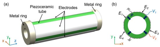
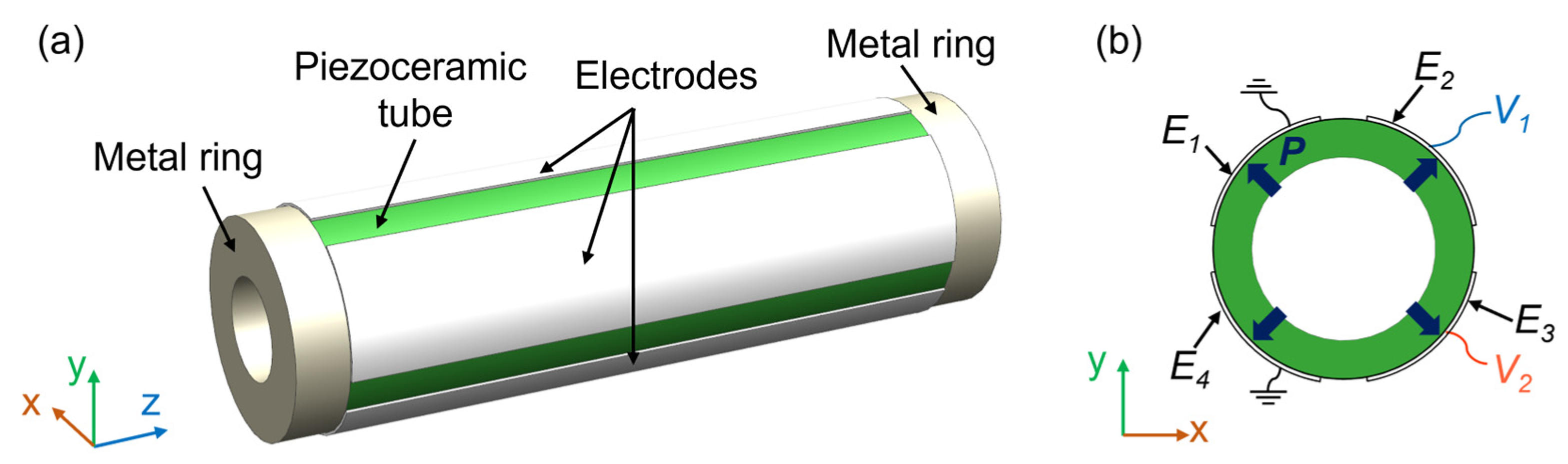
Figure 1 shows the structure of the proposed miniature bar-type USM stator operating in B1-B1 mode. The stator consists of one piezoelectric ceramic tube and two metallic stator parts bonded with epoxy resin. As depicted in Figure 1b, the outer electrode of the piezoelectric ceramic tube was divided into four identical regions, denoted as E1–E4, while the continuous inner electrode was used only for poling and was left electrically floating during motor operation. The four outer electrodes formed two orthogonal driving channels. In each channel, one outer electrode was connected to the sinusoidal voltage output (i.e., V1 or V2), and the opposite outer electrode was connected to the reference ground of the driving circuit. It should be noted that the floating inner electrode is capacitively coupled with all outer electrodes; thus, its potential is determined by the capacitive coupling among the driven and grounded outer electrodes. Nevertheless, because one outer electrode in each opposite pair is driven while the other is grounded, an asymmetric radial electric-field distribution is established across the ceramic wall. The resulting asymmetric strain distribution excites one B1 mode of the stator. To obtain the maximum vibration amplitude, the driving frequency is set near the resonant frequency of the B1 mode. Under two sinusoidal signals with a phase difference of ±90°, two orthogonal B1 modes are excited and superimposed in the piezoelectric ceramic tube, thereby generating a hula-hoop-like wobbling motion of the whole piezoelectric stator.
Figure 1.
Schematic structure of the miniature bar-type USM stator: (a) The three-dimensional model of the proposed USM stator; (b) Cross-section and excitation method of the piezoelectric ceramic tube.
2.2. Operating Principle and Theoretical Model
The elliptical vibration trajectory of particles on the stator surface is the key prerequisite for USM operation. Therefore, the vibration behavior of the stator is first analyzed theoretically. The voltage signals V1 and V2 are applied to the electrode input ends named CH1 and CH2, respectively. When the phase difference between the two signals is −90°, they satisfy the following relationships:
where V10 and V20 are the voltage amplitudes, and ω is the frequency of the B1 mode.
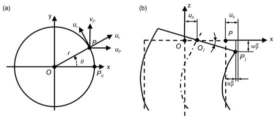
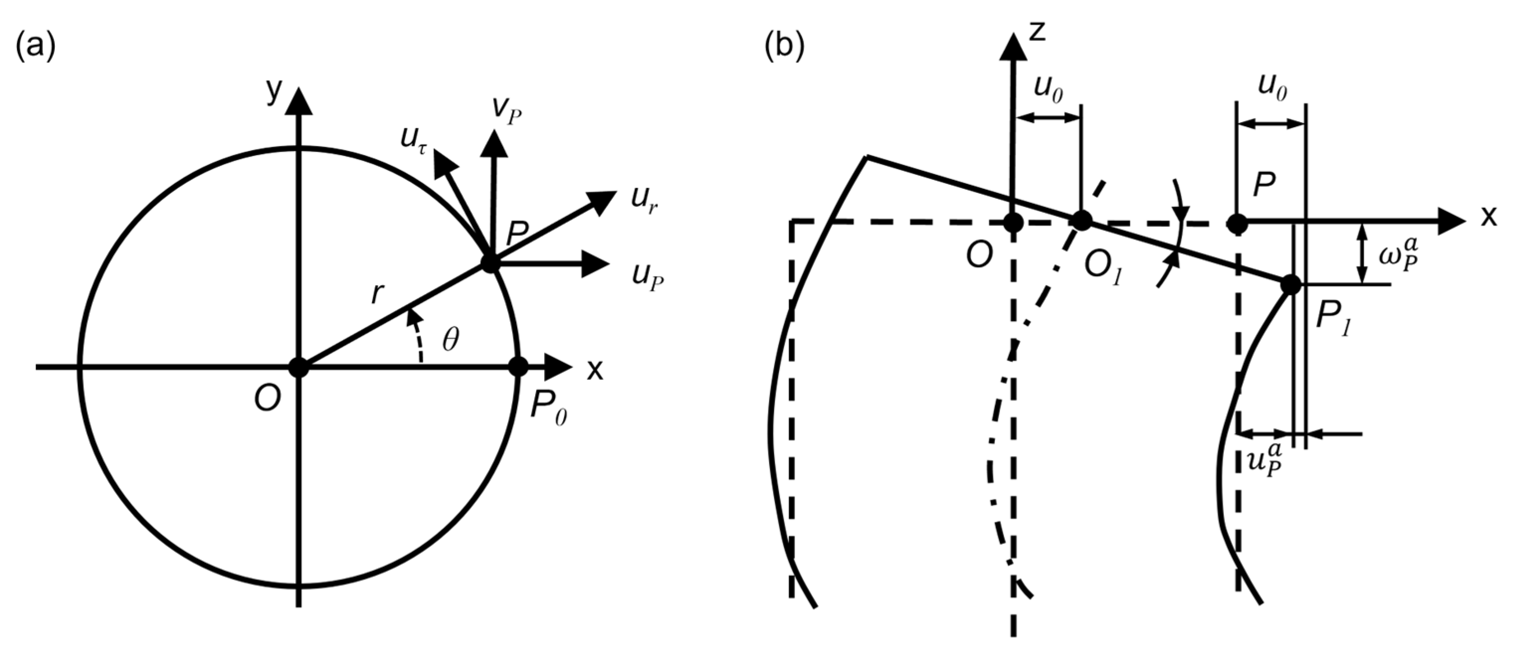
Let O be the intersection point between the stator axis and the upper end face, and let P(x, y) be an arbitrary point on the upper end plane, as shown in Figure 2a. When CH1 is excited alone and the influences of other modes and damping are ignored, the displacement response u0 in the x direction of point O and the angular displacement response β of the end face can be expressed as:
where W0 and are the maximum lateral displacement and maximum angular displacement of point O, respectively.
Figure 2.
Deformation of the driving end face under CH1 excitation: (a) Location of point P on end surface of stator; (b) Displacement of point P.
In the case of small deformation, the bending deformation of the stator satisfies the plane hypothesis. Therefore, the displacement responses of point P in the x and z directions can be approximately derived as [26]:
Similarly, when CH2 is excited alone, the displacement responses of point P in the y and z directions are:
When CH1 and CH2 are excited simultaneously, the z-direction displacement response of point P is:
Equation (9) shows that the z-direction displacement response of point P depends on both time t and circumferential angle θ, exhibiting a harmonic wave that rotates along the circumferential direction without fixed nodes or antinodes. This indicates that the bending-mode-based bar-type USM operates as a traveling-wave motor.
By decomposing uP and vP into the radial and tangential directions of point P, the radial and tangential displacement components, ur and uτ, can be obtained as:
Equations (10) and (11) indicate that both the radial and tangential displacement responses of point P follow traveling-wave equations. Combining the displacement components along the radial, tangential, and z directions in pairs according to Equations (9)–(11), the motion trajectory of point P on each coordinate plane can be obtained. Specifically, combining the tangential and z-direction displacement components yields the motion equation:
Thus, the vibration trajectory projected onto the plane composed of the tangential and z directions is an ellipse. When the rotor is elastically pressed onto the driving end face of the stator, the tangential displacement of this ellipse produces a relative motion tendency between the contact particles on the stator and the rotor, thereby generating the torque that drives the rotor.
Combining the radial and z-direction displacement components gives:
This result indicates that the vibration trajectory projected onto the plane composed of the radial and z directions is a straight line. If the rotor stiffness is excessively high, radial sliding may occur at the stator-rotor contact interface, causing energy dissipation and reducing motor efficiency.
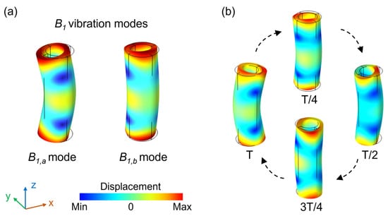
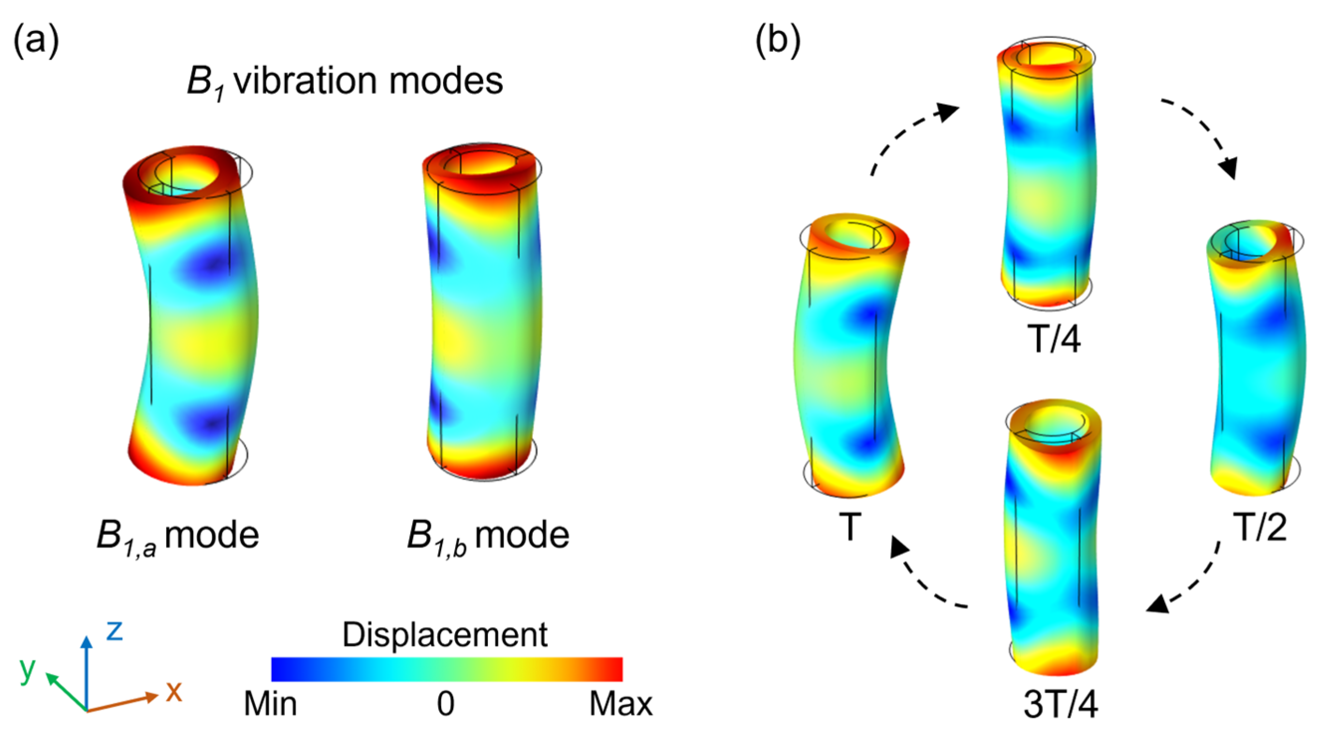
To visualize the driving principle, the piezoelectric-device module in COMSOL Multiphysics 6.2 was used to simulate the vibration modes of the piezoelectric stator and its vibration behavior. As depicted in Figure 3a, identical-frequency B1 vibration modes can be excited in x-z and y-z planes, which are respectively named as B1,a and B1,b modes. And there are two nodal lines in the middle region of the piezoceramic tube. When the phase difference between CH1 and CH2 is −90°, the piezoceramic tube forms a counterclockwise hula-hoop-like motion, as shown in Figure 3b. These finite-element simulation results confirm the feasibility and reliability of the proposed B1-B1 operating mode.
Figure 3.
Simulated vibration modes of the bar-type USM stator: (a) The B1 vibration modes; (b) Simulated vibration sequence of the stator.
3. Characteristics of the B1-B1 Piezoelectric Stator
To balance electromechanical coupling and heat generation, PZT-4 ceramic with the piezoelectric strain coefficients d33, d31, and d15 of 2.8 × 10⁻¹⁰ C/N, −1.0 × 10⁻¹⁰ C/N, and 4.2 × 10⁻¹⁰ C/N was selected as the material for the piezoceramic tube. The B1-B1 mode is a same-type mode driving method, and the piezoelectric ceramic tube has high structural symmetry. Therefore, the two B1 modes of the ceramic tube naturally have the same resonant frequency, which is expected to drift together with environmental temperature. Because heterogeneous-mode coupling is not required, the dimensions of the piezoceramic tube can be designed with high flexibility.
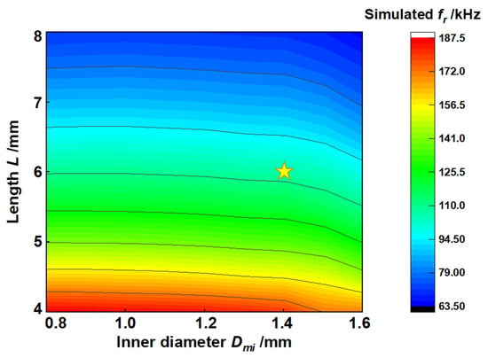
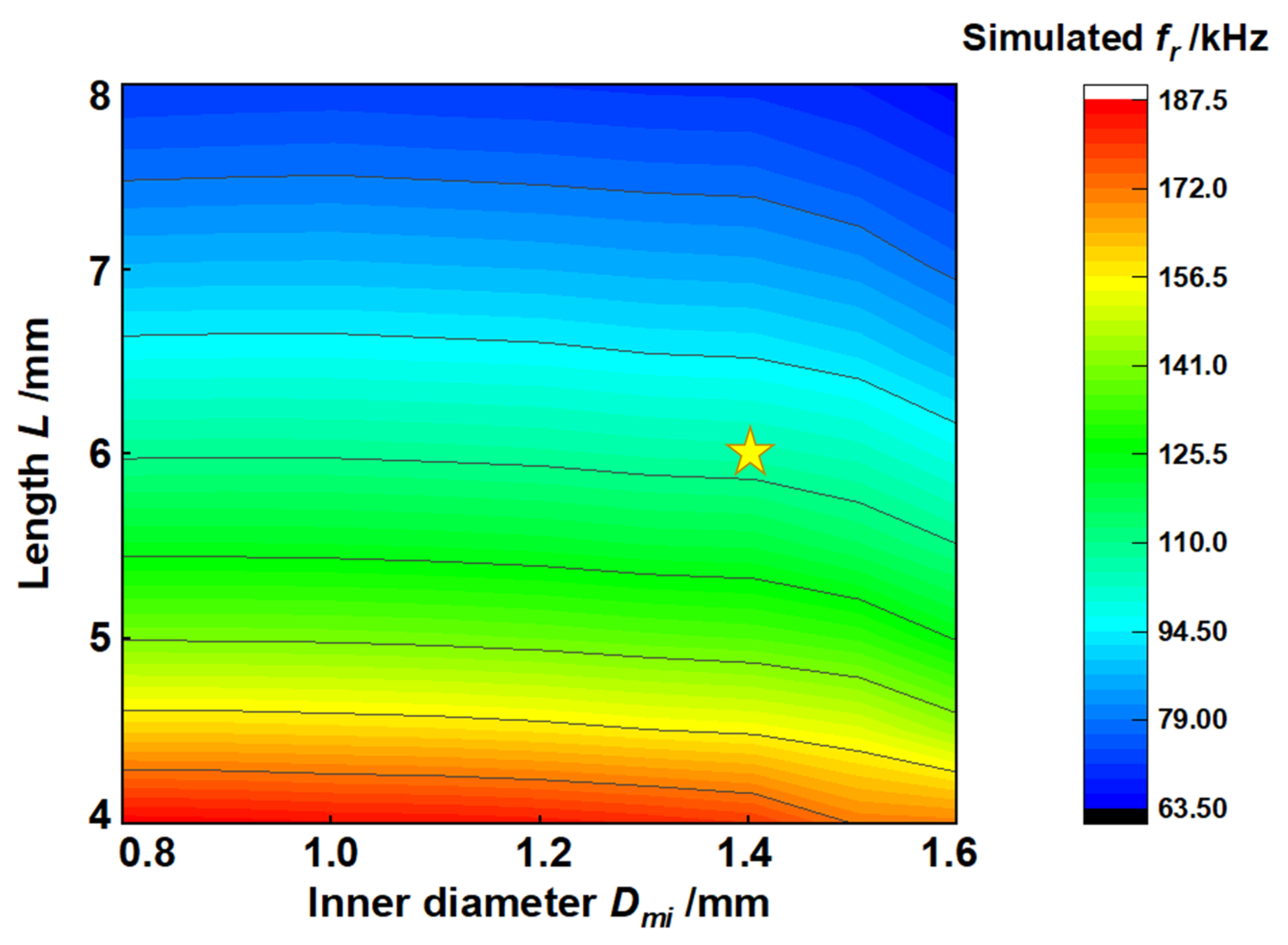
Considering the miniaturization requirement, the outer diameter of the piezoceramic tube was selected as 2 mm. When the thickness and inner diameter of the metal rings were fixed at 0.5 mm and 1 mm, respectively, the resonant frequency fr of the B1 mode under different tube lengths L and inner diameters Dmi was simulated, as shown in Figure 4. The simulation results demonstrate that fr decreases nonlinearly with increasing L and Dmi. Considering the reliability of thin-wall ceramic fabrication, the final ceramic tube was designed with a length of 6 mm and an inner diameter of 1.4 mm, corresponding to a simulated resonant frequency of 105.72 kHz, which corresponds to the position of the star in Figure 4.
Figure 4.
Simulated resonant frequency fr of the ceramic tube operating in the B1 mode as a function of tube length L and inner diameter Dmi.
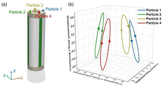
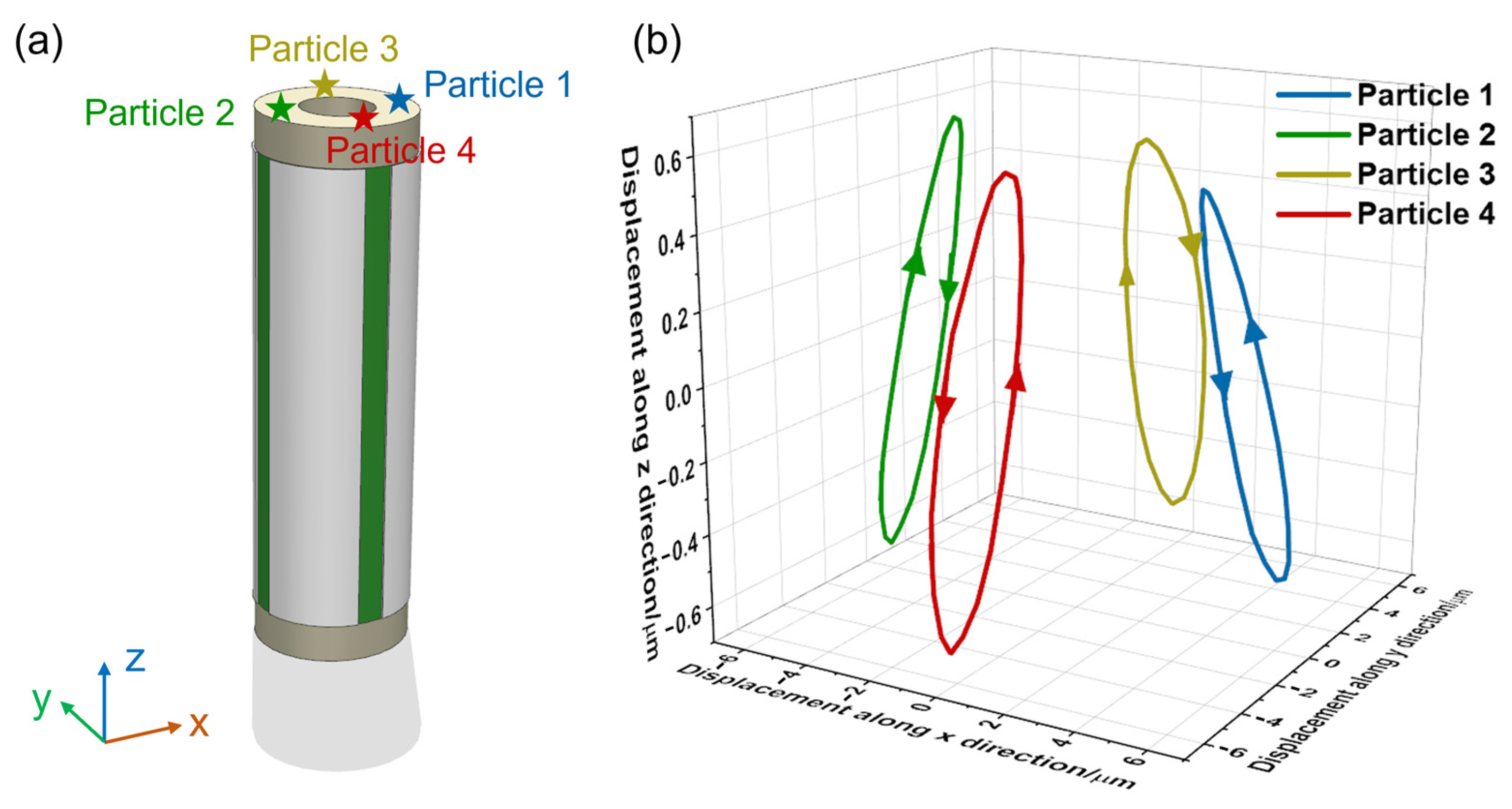
For this optimized size, four uniformly distributed particles on the stator end face, as shown in Figure 5a, were selected for transient simulation over one vibration period. With a sinusoidal driving signal of 105.72 kHz and 200 Vpp, the simulated vibration trajectories are depicted in Figure 5b. Three characteristics can be clearly observed. First, the vibration trajectories of the particles are elliptical and inclined relative to the x-y plane. Second, when each particle trajectory is observed from the center of the ceramic tube, the rotation direction is counterclockwise, and the particles are located at different positions of their ellipses at a given moment. Only when the z-direction displacement of the particles reaches the maximum can the rotor be driven to rotate. Third, the peak-to-peak displacement amplitudes along the x, y, and z directions are 2.5 μm, 2.2 μm, and 1.0 μm, respectively. These simulation results provide a basis for fabricating the motor prototype.
Figure 5.
Simulated vibration trajectories of four particles on the stator end face: (a) The positions of four particles; (b) The simulated vibration trajectories of four particles.
The piezoceramic tube and the two metal rings were then bonded with epoxy resin. An impedance analyzer (4294A, Agilent Technologies, Santa Clara, CA, USA) was used to measure the dielectric and impedance spectra of the piezoelectric stator to confirm the actual resonant state of the B1 mode. Because the outer electrode of the ceramic tube was divided into four regions, the four regions were tested separately. The differences in capacitance, dielectric loss, resonant frequency, and minimum impedance among the four regions were all within 5%, satisfying the requirements for stable actuation. The experimentally measured resonant frequency was approximately 113.6 kHz, which differs from the simulated result by 7.88 kHz. Considering fabrication errors, assembly errors, and material-property nonuniformity, this difference is acceptable and further verifies the feasibility of the simulation analysis.
4. Actuation Experiments
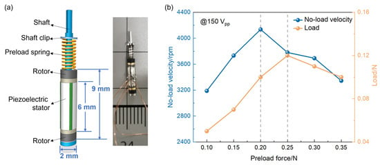
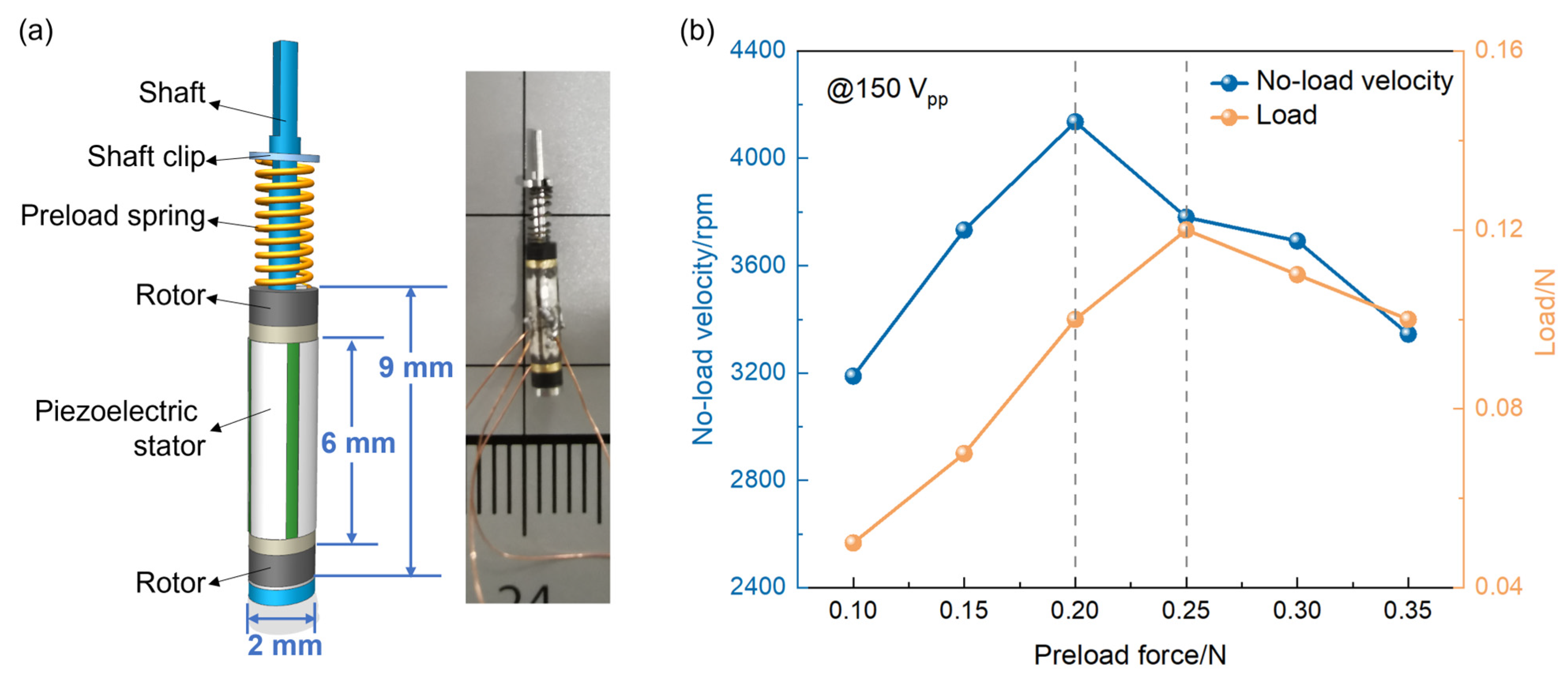
The theoretical analysis, numerical simulation, and impedance measurement above demonstrate that the proposed piezoelectric stator structure and B1-B1 operating mechanism can successfully generate elliptical vibration in one stator. To evaluate the output performances of the stator as a USM, a prototype was designed and fabricated, as shown in Figure 6a. The prototype consists of a bar-type stator operating in the B1-B1 mode, two rotors, a shaft, a preload spring, and a shaft clip. The bar-type stator is elastically pressed against one pair of rotors via the preload spring. By changing the thickness of the shaft clips from 0.45 mm to 0.70 mm, the preload applied to the stator can be tuned. As illustrated in Figure 6b, with the increase in the preload force, the no-load velocity and load capacity both tend to rise and then fall, and reach the maximum values at the preload force of 0.20 N and 0.25 N, respectively. To get better load capacity, a preload force of 0.25 N was chosen in this work.
Figure 6.
The structure and preload force of the millimeter-scale bar-type USM: (a) Three-dimensional structure and photograph of the USM; (b) The relationships between the output performances and the preload force.
The experimental setup for evaluating the driving performances consists of a driving module, a displacement measuring module, and a monitoring module. Two-phase sinusoidal signals were generated by a signal generator (AFG3022B, Tektronix, Beaverton, OR, USA), amplified by a high-voltage power amplifier (2350, Tegam, Geneva, NY, USA), and monitored by an oscilloscope (MSOX4024A, Keysight, Santa Rosa, CA, USA). Then, the moving characteristics were measured using the high-precision laser Doppler vibrometer (LV-S01, Sunny, Yuyao, China). In the later stage of the experiment, a driving control board capable of simultaneously controlling eight USMs was developed, which can generate two high-frequency high-voltage sinusoidal signals with an adjustable ±90° phase difference. It consists of a voltage-controlled frequency generator and a frequency-division/phase-shifting circuit. A phase-locked-loop closed-loop circuit is adopted to lock the signal phase of the piezoelectric ceramic and realize frequency tracking, thereby suppressing resonant-frequency drift caused by heat generation in the piezoelectric ceramic.
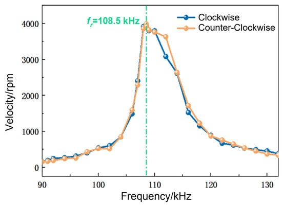
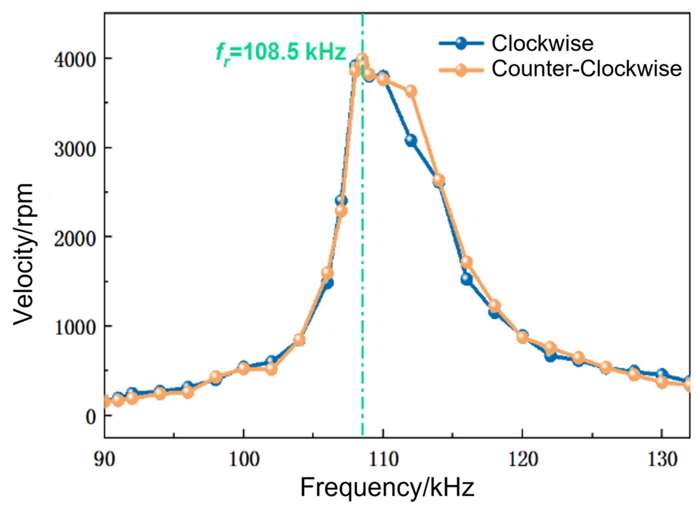
To determine the reliable operating frequency range of the bar-type USM, the relationship between no-load shaft velocity and driving frequency was investigated at an applied voltage of 150 Vpp, as shown in Figure 7. The prototype achieved stable bidirectional motion over a frequency range from 90 to 132 kHz, corresponding to a reliable bandwidth of 42 kHz. The no-load velocity reached its maximum value of approximately 3900 rpm at 108.5 kHz, indicating that this frequency is the actual resonant point of the motor prototype where the stator-rotor contact interface can obtain a larger tangential vibration velocity. This resonant operation is beneficial for obtaining high output performances from a compact millimeter-scale stator. However, the output performance is sensitive to frequency deviation near resonance, and long-term operation exactly at resonance may increase the risk of ceramic fracture caused by increased mechanical stress and heat generation. Therefore, considering both output performance and operational reliability, the optimal driving frequency for the subsequent tests was set as 110 kHz. It can also be observed that the clockwise and anticlockwise velocities show a slight difference at some high frequencies, which is mainly attributed to manufacturing and assembly tolerances, such as slight dimensional errors of the piezoceramic tube and metal rings, nonuniformity of electrode segmentation and poling, small deviations in the stator-rotor contact condition, and asymmetry of the preload/friction interface.
Figure 7.
Bidirectional no-load velocity of the miniature bar-type USM as a function of driving frequency.
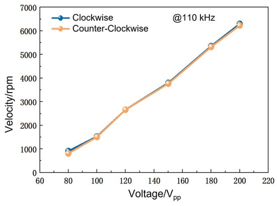
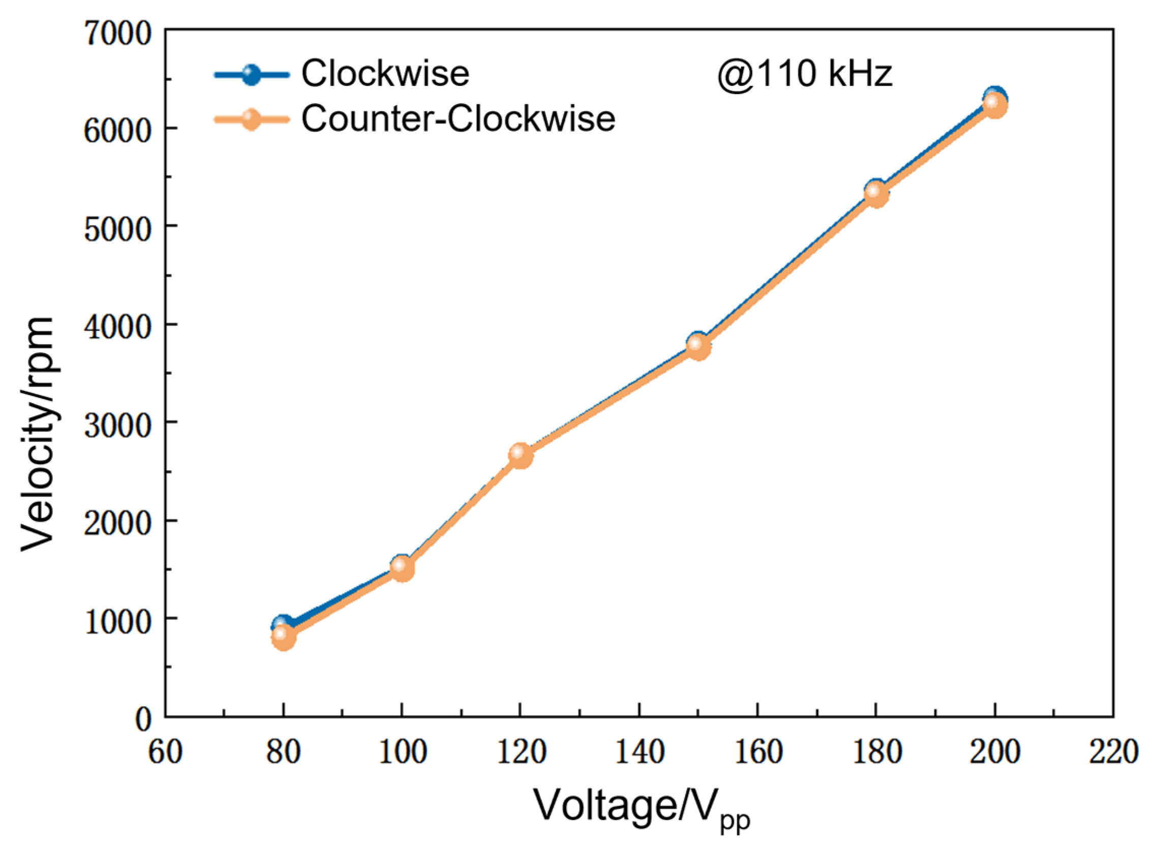
At the driving frequency of 110 kHz, the relationship between no-load velocity and driving voltage in both directions is shown in Figure 8. Under the present preload condition, no stable continuous rotation was observed when the driving voltage was lower than approximately 80 Vpp. Although the stator could still vibrate in this voltage range, the vibration amplitude and tangential driving force were insufficient to overcome the friction at the stator-rotor interface induced by the preload. Therefore, 80 Vpp was regarded as the approximate starting voltage for stable macroscopic rotation of the present prototype. Once the driving voltage exceeded 80 Vpp, the velocity of the USM in both directions increased almost linearly with the driving voltage and reached a maximum value of 6200 rpm at 200 Vpp. This result indicates that the output velocity can be directly controlled by the input voltage. The high-velocity operation capability is closely related to the large vibration amplitude of the metallic stator end face and the small contact diameter between the stator and rotor, which will expand the application range of this USM. The velocity curves in the two directions almost overlap, further confirming the symmetry of bidirectional motion and the symmetry of the excited B1,a and B1,b modes. To ensure long-term reliability and avoid cracking or fracture of the piezoelectric ceramic, the driving voltage should not exceed 200 Vpp.
Figure 8.
Bidirectional no-load velocity of the miniature bar-type USM as a function of driving voltage.
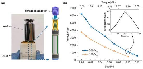
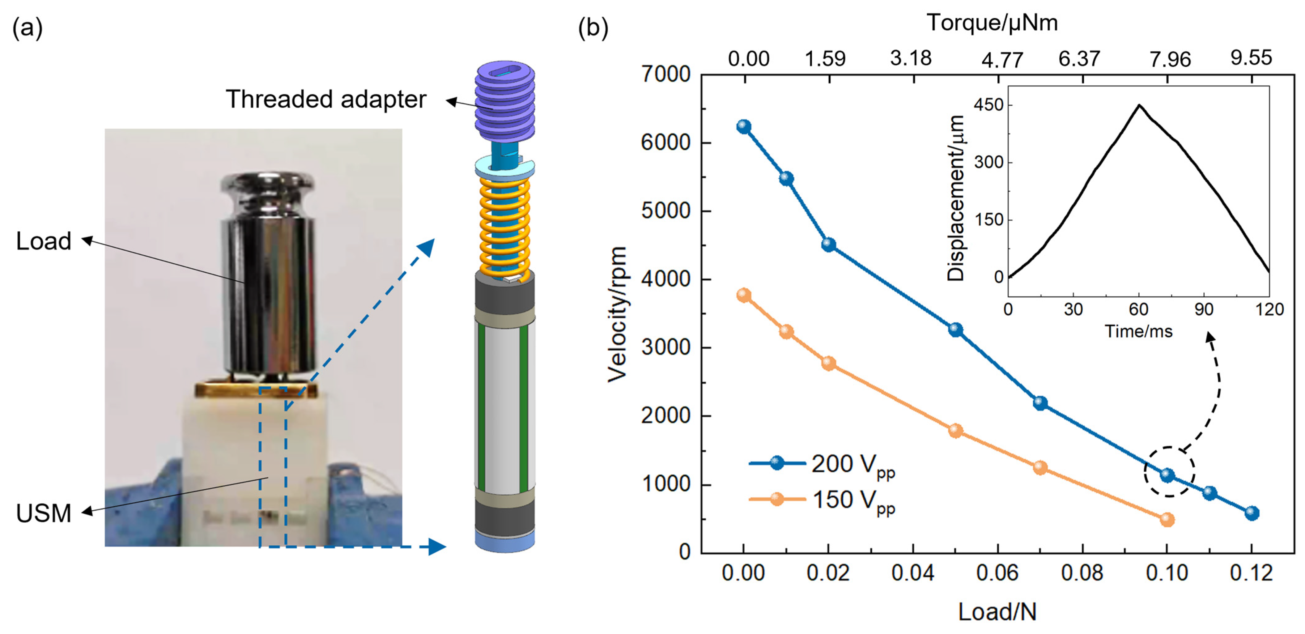
The rotational motion of the rotor was then converted into linear motion of an output component by using a threaded adapter and housing, as shown in Figure 9a, to test the load-driving capability of the motor. Figure 9b shows the measured rotary velocity of the shaft as a function of mechanical load under different driving voltages at 110 kHz. The results denote a negative linear correlation between the velocity and load, and the maximum load is 0.12 N under a voltage of 200 Vpp. If the transmission efficiency of the screw is taken as 0.8, the maximum torque output of the USM is 9.55 μNm. According to the volume of the driving part, the output force density reached 10.7 mN/mm3 (i.e., 0.85 μNm/mm3), which is significantly higher than those of typical resonant USMs [12,13,14,23,27,28]. This high force density benefits from the rational friction-coupling design between the stator and rotor and demonstrates the substantial advantage of piezoelectric actuation in miniaturized devices.
Figure 9.
Load-capacity test of the bar-type motor: (a) Schematic structure for linearly driving a mass load; (b) Plots of the rotary velocity versus mechanical load under varying driving voltages.
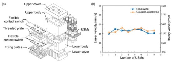
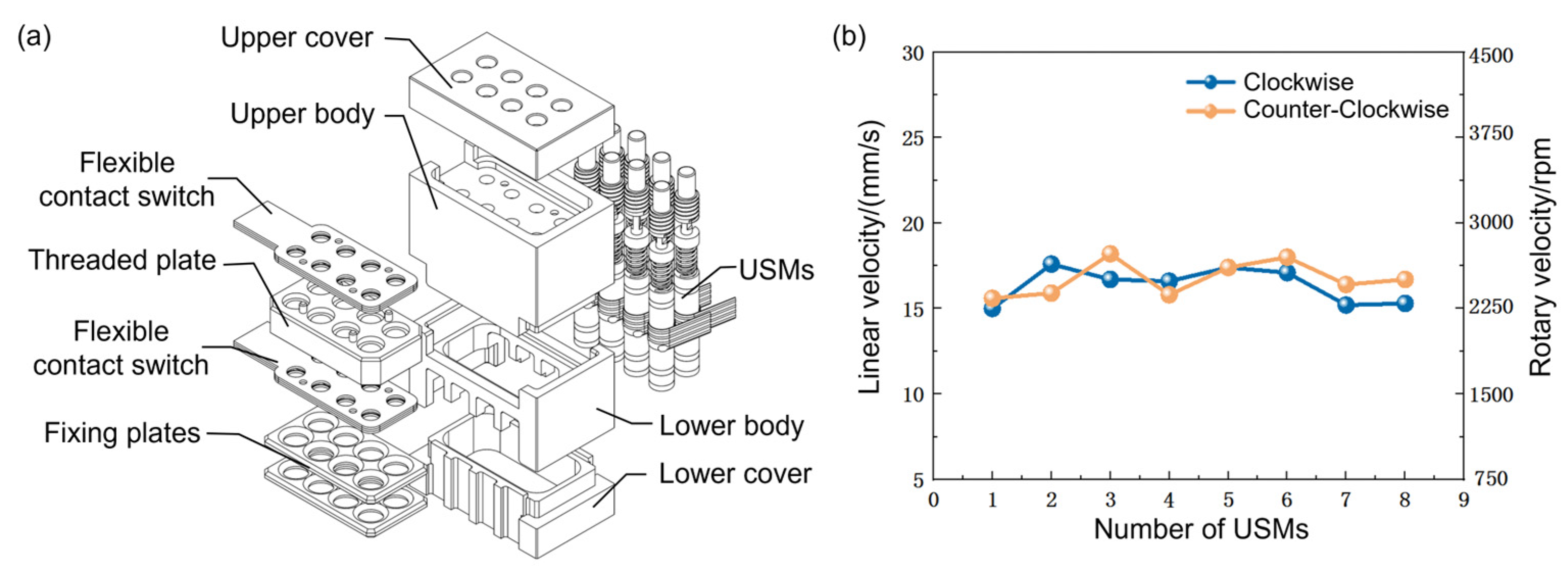
As an application demonstration, eight bar-type USMs were integrated into one module in a 2 × 4 array. The center-to-center distance between adjacent motors was only 2.6 mm, and threaded connections were used to convert rotary motion into linear motion. The module consists of an upper cover, an upper body, a lower body, a lower cover, a threaded plate, two fixing plates, two flexible contact switches, and eight bar-type motors, as shown in Figure 10a. The performances of the eight USMs were tested, and their no-load velocities at 120 Vpp and 110 kHz are summarized in Figure 10b. The performance fluctuation among the eight motors was within 10%. Considering the advantages of closed-loop control, it is reasonable to expect that smaller performance fluctuation and more reliable repeatability can be obtained when closed-loop control is adopted. These results further demonstrate the high integration capability and miniaturization advantage of the proposed motor, suggesting broad application prospects in micro/nano-satellite systems and in large flexible structures requiring parallel multipoint active vibration control.
Figure 10.
An application case of integrating eight USMs into a single module: (a) Structural schematic of the arrayed bar-type USM module; (b) Performance consistency of eight USMs.
For the synchronous operation of multiple motors, electromagnetic interference should be considered in the arrayed configuration. Since the proposed USMs are driven by the inverse piezoelectric effect rather than electromagnetic field interaction, the motor stators themselves are not expected to generate strong magnetic fields, which is an inherent advantage over electromagnetic motors. Therefore, the main electromagnetic compatibility concern comes from the high-frequency and high-voltage driving circuits. In practical circuit design, electrical crosstalk between adjacent driving channels, capacitive coupling among high-voltage signal lines, common-ground interference, and radiated/conducted emissions from the power amplifier should be carefully suppressed by separated driving channels, proper grounding, sufficient insulation spacing, compact wiring, and shielding when necessary.
Based on the above experimental results, a hierarchical control strategy can be considered for the proposed B1-B1 bar-type USM. The inner loop can provide phase locking and resonance-frequency tracking to keep the stator operating near its actual resonant frequency, while the outer velocity or position feedback loop can regulate the output motion by adjusting the excitation frequency, voltage amplitude, or phase relationship. For the arrayed configuration, independent driving channels combined with an outer coordination loop may be used to improve the displacement consistency of multiple USMs. Robust nonlinear control methods, such as cascade sliding mode control, may also be introduced to compensate for frictional uncertainty, load disturbance, and piezoelectric nonlinearities [11,29].
Table 1 compares the optimal operating conditions and driving performances of the proposed B1-B1 mm-scale bar-type USM with those of previously reported resonant piezoelectric motors. The proposed USM not only has a simple and compact structure but also exhibits excellent comprehensive performance, including high load/torque density, high driving velocity, and wide operating bandwidth. In particular, the proposed motor achieves a load density of 10.7 mN/mm3 and an equivalent torque density of 0.85 μNm/mm3, showing its advantage in volume-normalized output performance. In addition, as long as the input electric field remains within the safe range, the piezoelectric motor can operate for a long time without obvious temperature rise or performance degradation.
Table 1.
Performance comparison between the proposed miniature bar-type USM and reported resonant USMs.
5. Conclusions
In summary, a miniature bar-type USM operating in the B1-B1 mode with an outer diameter of only 2 mm was developed to improve the comprehensive performance of the miniaturized USM. Through theoretical analysis and finite-element simulation, the symmetrical vibration characteristics of the B1 modes were utilized to design a piezoelectric ceramic tube with two metal rings bonded at its ends, for converting the microscopic elliptical vibration trajectories of particles into macroscopic rotary output of the shaft through friction coupling. Because the motor is driven by same-type vibration modes, it avoids mode-decoupling problems and complicated dimensional design. In addition, the floating-electrode driving method greatly reduces the difficulty of electrode wiring and soldering.
Experimental tests show that the proposed USM exhibits excellent comprehensive driving performance, including a millimeter-scale structure (a stator outline of φ2 × 6 mm3), a wide stable operating bandwidth (90–132 kHz), a high no-load velocity (~6200 rpm), and a high-torque density (0.85 μNm/mm3). Eight USMs were further integrated into one compact arrayed module, verifying both the high integration capability and the controllable and stable output performance of the motor. These results indicate that the proposed miniature bar-type USM is highly promising as a high-precision, high-dynamic, and light-weight driving source for space mechanisms, such as precision pointing mechanisms, parallel multipoint active vibration isolation platforms, and arrayed micro-gimbals.
Author Contributions
Conceptualization, Z.L. and S.D.; methodology, Z.L. and S.D.; validation, Z.L., X.Y. and L.Y.; investigation, L.Y.; data curation, Z.L. and X.Y.; writing—original draft preparation, Z.L.; writing—review and editing, G.Z. and S.D.; visualization, Z.L. and X.Y.; supervision, S.D.; project administration, G.Z. and S.D.; funding acquisition, Z.L. and S.D. All authors have read and agreed to the published version of the manuscript.
Funding
This research was funded by the National Natural Science Foundation of China, grant number 52502131.
Data Availability Statement
All data needed to evaluate the conclusions in the paper are present in the paper. Additional data related to this paper may be requested from the authors.
Conflicts of Interest
The authors declare no conflicts of interest.
References
- Cho, M.; Hirokazu, M.; Graziani, F. Introduction to Lean Satellite and ISO Standard for Lean Satellite. In Proceedings of the 2015 7th International Conference on Recent Advances in Space Technologies (RAST), Istanbul, Turkey, 16–19 June 2015; pp. 789–792. [Google Scholar]
- Gonzalez, C.E.; Rojas, C.J.; Bergel, A.; Diaz, M.A. An Architecture-Tracking Approach to Evaluate a Modular and Extensible Flight Software for CubeSat Nanosatellites. IEEE Access 2019, 7, 126409–126429. [Google Scholar] [CrossRef] [Scilit]
- Euroconsult. Available online: https://www.euroconsult-ec.com/ (accessed on 6 June 2026).
- Mohith, S.; Upadhya, A.R.; Navin, K.P.; Kulkarni, S.M.; Rao, M. Recent Trends in Piezoelectric Actuators for Precision Motion and Their Applications: A Review. Smart Mater. Struct. 2021, 30, 013002. [Google Scholar] [CrossRef] [Scilit]
- Wang, Y.Z.; Deng, J.; Li, J.; Zhang, S.J.; Chen, W.S.; Liu, Y.X. Progress, Challenges, and Prospects of Miniature Ultrasonic Motors. Adv. Mater. Technol. 2025, 10, e00711. [Google Scholar] [CrossRef] [Scilit]
- Successful Application of the Ultrasonic Motor Developed by Nanjing University of Aeronautics and Astronautics in the Chang’e-3 Infrared Spectrometer. J. Vib. Meas. Diagn. 2014, 34, 199.
- Tian, X.; Liu, Y.X.; Deng, J.; Wang, L.; Chen, W. A Review on Piezoelectric Ultrasonic Motors for the Past Decade: Classification, Operating Principle, Performance, and Future Work Perspectives. Sens. Actuators A Phys. 2020, 306, 111971. [Google Scholar] [CrossRef] [Scilit]
- Zhang, J.Y.; Yang, L.; Ma, C.; Ren, W.; Zhao, C.; Wang, F. Improving Efficiency of Traveling Wave Rotary Ultrasonic Motor by Optimizing Stator. Rev. Sci. Instrum. 2019, 90, 056104. [Google Scholar] [CrossRef] [Scilit] [PubMed]
- Li, J.K.; Huang, H.J.; Morita, T. Stepping Piezoelectric Actuators with Large Working Stroke for Nano-Positioning Systems: A Review. Sens. Actuators A Phys. 2019, 292, 39–51. [Google Scholar] [CrossRef] [Scilit]
- Lv, X.M.; He, Z.Z.; Zhu, R.Q.; Wang, B.; Wang, X.Y.; Zhu, R.L.; Li, Z.M.; Zhang, C.L.; Dong, S.X. A Millimeter-Scale, High-Power Density Linear Piezoelectric Resonant Actuator. IEEE Trans. Ind. Electron. 2025, 72, 10519–10530. [Google Scholar] [CrossRef] [Scilit]
- Dong, S.X.; Lim, S.P.; Lee, K.H.; Zhang, J.D.; Lim, L.C.; Uchino, K. Piezoelectric Ultrasonic Micromotor with 1.5 mm Diameter. IEEE Trans. Ultrason. Ferroelectr. Freq. Control 2003, 50, 361–367. [Google Scholar] [CrossRef] [Scilit] [PubMed]
- Kanda, T.; Makino, A.; Ono, T.; Suzumori, K.; Morita, T.; Kurosawa, M.K. A Micro Ultrasonic Motor Using a Micro-Machined Cylindrical Bulk PZT Transducer. Sens. Actuators A Phys. 2006, 127, 131–138. [Google Scholar] [CrossRef] [Scilit]
- Morita, T.; Kurosawa, M.K.; Higuchi, T. A Cylindrical Micro Ultrasonic Motor Using PZT Thin Film Deposited by Single Process Hydrothermal Method (φ 2.4 mm, L = 10 mm Stator Transducer). IEEE Trans. Ultrason. Ferroelectr. Freq. Control 1998, 45, 1178–1187. [Google Scholar] [CrossRef] [Scilit] [PubMed]
- Li, Z.M.; Zhu, R.Q.; Yi, X.Y.; Dong, S.X. A High-Power-Density Piezoelectric Actuator Operating in Bicycling Movement Mechanism. IEEE Trans. Ind. Electron. 2023, 70, 6090–6098. [Google Scholar] [CrossRef] [Scilit]
- Koc, B.; Cagatay, S.; Uchino, K. A Piezoelectric Motor Using Two Orthogonal Bending Modes of a Hollow Cylinder. IEEE Trans. Ultrason. Ferroelectr. Freq. Control 2002, 49, 495–500. [Google Scholar] [CrossRef] [Scilit] [PubMed]
- Deng, J.; Wu, K.; Wang, Y.Z.; Li, J.; Guan, J.H.; Zhang, S.J.; Liu, Y.X. Development of a 2-DOF Rotary Ultrasonic Actuator for Reflector Steering. IEEE Trans. Ind. Electron. 2026, 73, 12068–12078. [Google Scholar] [CrossRef] [Scilit]
- Peled, G.; Yasinov, R.; Karasikov, N. Performance and Applications of L1B2 Ultrasonic Motors. Actuators 2016, 5, 15. [Google Scholar] [CrossRef] [Scilit]
- Yun, C.H.; Ishii, T.; Nakamura, K.; Ueha, S.; Akashi, K. A High Power Ultrasonic Linear Motor Using a Longitudinal and Bending Hybrid Bolt-Clamped Langevin Type Transducer. Jpn. J. Appl. Phys. 2001, 40, 3773. [Google Scholar] [CrossRef] [Scilit]
- Li, Z.M.; Bian, L.; Yi, X.Y.; Zhu, R.Q.; Yuan, X.T.; Dong, S.X. A Co-Fired Multilayer PMnS-PZT Ceramic Based Linear Piezoelectric Ultrasonic Micromotor with a High-Load-Density. Appl. Phys. Lett. 2022, 120, 082902. [Google Scholar] [CrossRef] [Scilit]
- Li, Z.M.; Yi, X.Y.; Zhu, R.Q.; Yu, Z.H.; Yuan, X.T.; PourhosseiniAsl, M.J.; Dong, S.X. A Symmetric-Actuating Linear Piezoceramic Ultrasonic Motor Capable of Producing a Scissoring Effect. Research 2023, 6, 0156. [Google Scholar] [CrossRef] [Scilit] [PubMed]
- Delibas, B.; Koc, B. L1B2 Piezo Motor Using d33 Effect. In Proceedings of the ACTUATOR 2018, 16th International Conference on New Actuators, Bremen, Germany, 25–27 June 2018; pp. 1–4. [Google Scholar]
- Liu, Y.X.; Chen, W.S.; Feng, P.; Liu, J.K.; Shi, S.J. Miniaturization of a U-Shape Linear Piezoelectric Motor with Double Feet. Sens. Actuators A Phys. 2014, 214, 95–100. [Google Scholar] [CrossRef] [Scilit]
- Xin, X.D.; Gao, X.Y.; Wu, J.G.; Li, Z.M.; Chu, Z.Q.; Dong, S.X. A Ring-Shaped, Linear Piezoelectric Ultrasonic Motor Operating in E01 Mode. Appl. Phys. Lett. 2020, 116, 152902. [Google Scholar] [CrossRef] [Scilit]
- Huang, W.Q.; Ma, X.L.; Bi, Y.H.; Zhao, C.S. Study on the Motion Mechanism of a Bar-Type Traveling-Wave Ultrasonic Motor. J. Vib. Shock 2004, 23, 48–51. [Google Scholar]
- Uchino, K. Ferroelectric Devices, 2nd ed.; CRC Press: Boca Raton, FL, USA, 2010. [Google Scholar]
- Zhao, C.S. Ultrasonic Motors, 1st ed.; Springer: Heidelberg, Germany, 2011. [Google Scholar]
- Chen, Z.H.; Li, X.; Chen, J.; Dong, S.X. A Square-Plate Ultrasonic Linear Motor Operating in Two Orthogonal First Bending Modes. IEEE Trans. Ultrason. Ferroelectr. Freq. Control 2013, 60, 115–120. [Google Scholar] [CrossRef] [Scilit] [PubMed]
- Liu, Y.X.; Yan, J.P.; Wang, L.; Chen, W.S. A Two-DOF Ultrasonic Motor Using a Longitudinal–Bending Hybrid Sandwich Transducer. IEEE Trans. Ind. Electron. 2019, 66, 3041–3050. [Google Scholar] [CrossRef] [Scilit]
- Mercorelli, P. A Robust Cascade Sliding Mode Control for a Hybrid Piezo-Hydraulic Actuator in Camless Internal Combustion Engines. IFAC Proc. Vol. 2012, 45, 790–795. [Google Scholar] [CrossRef] [Scilit]

Disclaimer/Publisher’s Note: The statements, opinions and data contained in all publications are solely those of the individual author(s) and contributor(s) and not of MDPI and/or the editor(s). MDPI and/or the editor(s) disclaim responsibility for any injury to people or property resulting from any ideas, methods, instructions or products referred to in the content. |
© 2026 by the authors. Licensee MDPI, Basel, Switzerland. This article is an open access article distributed under the terms and conditions of the Creative Commons Attribution (CC BY) license.