


Abstract
A two-degree-of-freedom, self-exciting pneumatic vibroactuator was investigated. The feature of this vibroactuator is that, along with the sliding-reciprocating movement of the working body along the axis, it also rotates about this axis. A new mathematical model of this vibroactuator is presented and solved using numerical methods. Comparisons of the results of numerical and experimental studies are described. The analyzed vibroactuator, supplemented with extended functional capabilities, is established for use in intensifying technological production processes.
1. Introduction
Pneumatic vibrotransducers are widely used across various scientific and industrial fields, depending on their intended use. In industrial and manufacturing processes, they are used for vibrocompaction of pharmaceutical powders [1], in room-temperature injection molding of ceramics [2], and as components of polishing machines [3]. They are also used in the production of concrete pipes and columns [4,5], in powder delivery systems for direct metal laser deposition [6], in cold spray systems for depositing polymer particles on polymer substrates [7,8], and in continuously vibrating powder bed reactors [9]. In construction and geotechnical applications, pneumatic vibrators are used for concrete made of hemp and rice husks [10], soil [11,12,13,14], and for soil compaction and leveling in lightweight aircraft [15]. They are also used to reduce internal particle friction during concrete delivery [16] and in fossil preparation processes [17]. In material handling and flow improvement, these devices are used to control membrane fouling [18], reduce powder adhesion to granulator walls [19], and improve processing of adhesives or poorly flowing materials in material handling equipment [20,21]. In advanced materials and high-tech applications, pneumatic vibrotransducers are used to eliminate defects in carbon fiber-reinforced polymer structures [22] and as vibrator components in complex technological systems [23]. In biomedical and biomechanical research, pneumatic vibrotransducers are used for calcaneal tendon vibration (frequency range 80–110 Hz) and to study the increase in residual force during submaximal and maximal contractions of the plantar flexor muscles, depending on the angle of the knee joint [24]. They are also used for focal muscle vibration [25] and muscle proprioception stimulation [26]. In agricultural and special-purpose systems, pneumatic vibrotransducers are used in cotton seeders [27] and reduced-gravity simulators [28].
Many authors have investigated active vibration control solutions in pneumatic systems [29,30,31]. Qiu and Zhao [29] applied the phase control method to a pneumatic actuator with a flexible manipulator. Gao et al. [30] proposed the use of piezoelectric actuators inside pneumatic actuators to reduce friction and generate vibrations more efficiently. Morales et al. [31] developed and experimentally tested an air suspension system in which the air flow direction allows changes in the system transfer function. These studies [32,33,34] examine the application of active and nonlinear control in pneumatic systems. Liang et al. [32] applied active control schemes to a pneumatic isolator to improve low-frequency isolation, particularly in the resonant range. Khajepour [33] proposed a nonlinear control method that enables the generation of any bias input for asymmetric actuators. Zhao et al. [34] experimentally compared pneumatic, piezoelectric, and hybrid oscillatory control using a PD control strategy. In Reference [35], a three-mode self-exciting pneumatic vibroactuator consisting of two elastically connected excitation chambers was studied. Its mathematical model was developed and numerically solved, and three modes of motion were determined. The numerical results were experimentally verified. This vibroactuator can be applied to increase the intensification of production processes.
The design and analysis of multi-degree-of-freedom (MDOF) vibration systems are important for a deeper understanding of the dynamics of complex mechanical systems and their vibration control capabilities. For example, Da Silva and Marques [36] investigated multi-degree-of-freedom nonlinear energy harvesters (MDOF-NES) for passive damping of spring-induced oscillations. The results of the study showed that the mass parameters of the MDOF-NES significantly affect the stability, amplitudes, and synchronization frequency range of the limit cyclic oscillations (LCO). These works highlight the potential of passive vibration control, which complements and provides a basis for further research on active and hybrid oscillatory control methods.
A lot of research has been done on the energy transducer over the last two decades. The original vibration transducer was as simple as a cantilever beam with a PE (piezoelectric) patch or a coil-magnet assembly. Through evolution, these have been integrated into a single hybrid system. The problem of frequency tuning was initially solved with a nonlinear transducer, but later the focus shifted to two DOFs (degrees of freedom) and then to multiple DOFs. Currently, the focus is on different branched systems with resonant or nonlinear configurations [37]. Vibration energy can be harvested using electromagnetic (EM) [38], piezoelectric (PE) [39,40], electrostatic (ES), triboelectric [41] or self-exciting transduction mechanisms. When a device uses more than one transduction mechanism, it is called a hybrid energy harvester [42]. Much research has been carried out on this topic. In Reference [43], the possibility of using helical beams in a cantilevered beam with a tip mass was investigated to harvest energy from ambient vibrations and to generate electrical voltage to supply the sensor nodes, without the need for wires and disposable batteries. The basic assumption was that the excitation was in-plane, with a constant frequency but variable direction. The parameters of the spiral beam were obtained by numerical iteration in finite element simulations, trying to achieve uniform stiffness at the end of the beam, so that the first two in-plane bending natural frequencies coincide. The researchers analyzed the dynamic behavior of MDOF systems using modal analysis methods. However, difficulties arise when dealing with systems that have singular matrices due to constraints. In such cases, a modified modal analysis approach can be applied within the framework of analytical dynamics. This approach facilitates the estimation of natural frequencies and system responses, even when traditional modal analysis methods may fail [44]. The behavior of MDOF structural systems is analyzed using different numerical methods, such as finite element analysis (FEA) and finite difference methods (FDM). These allow for detailed simulations and parametric studies that allow engineering solutions, such as structural response methods to all loads and forces, as in Reference [45]. Such analyses are essential for safe and efficient structures that can withstand dynamic environments. In practice, MDOF systems often behave indirectly due to factors such as joint friction. In [46], when the authors precisely controlled the position of a robot with six degrees of freedom, it was necessary to take into account the effects of friction between the links. Based on the results, the researchers found that a comprehensive nonlinear dynamic equation incorporating a Coulomb friction model can be developed to accurately simulate and control the robot’s motions. In [47], it is discussed that soft actuators are essential for soft robots and can also be used in rigid-body robots. In this paper, the researchers focus on methods to improve the adaptability of origami-inspired soft pneumatic actuators (OSPAs).
The researchers’ results in [48] show that in the field of pneumatic control valves, the partial order model has good adaptability and efficiency, and the two-degree-of-freedom partial order internal model control algorithm also effectively improves the accuracy, speed, and reliability of valve position control. In another paper [49], a new cooperative control strategy for 3-degree-of-freedom PM is proposed to achieve both synchronized and differential motion. A pneumatically controlled test bench was constructed to validate the effectiveness of the cooperative controller. The results in the paper show that the control method outperforms the PID controller.
The mentioned studies are mostly limited to specific systems and laboratory conditions, so the applicability of their results to practice is limited. In addition, passive MDOF-NES solutions and simple control strategies are sensitive to parameter changes and are effective only in narrow operating ranges. There is also a lack of integrated studies on passive, active, and hybrid oscillatory control methods.
Both system analysis and system identification are needed to study and characterize the dynamic behavior of complex vibrating structures. The identification of different systems involves the development of mathematical models based on experimental data, as in system response prediction. The design and analysis of MDOF vibration transducers involve a wide range of research, including innovative actuation techniques, advanced analysis techniques, numerical simulations, and system identification processes. Together, these subjects contribute to a deeper understanding and more effective control of the dynamic behavior of complex mechanical systems. Our research highlights the complex interplay between rotational motion, system nonlinearity and self-excited vibrations in rotating machines. This approach is a promising way to improve the stability and performance of a wide range of mechanical and hydraulic systems. Pneumatic actuators are lightweight, with high acceleration and speed, but suffer from oscillations and lower force. Hydraulic actuators excel in force and displacement but are heavy and energy-intensive. Electric actuators offer precise, efficient, and smooth control, but with lower peak velocity and limited displacement. The main results of the various types of vibroactuator systems compared are presented in Table 1.
Table 1.
Parameters of hydraulic, pneumatic, and electric actuator systems [50].
Pneumatic vibroexciters on an air cushion, with multifunctional capabilities: harmonic and non-harmonic change in the working body movement, step change in vibration parameters, and impact mode of the working body. Understanding these mechanisms is essential for the development of effective prediction strategies, thus ensuring the reliable operation of rotating equipment. The aim of this study is to demonstrate that a novel aspect of controlling self-excited vibrations through pressure modulation is the ability to dynamically adjust system parameters, thereby mitigating or eliminating unwanted oscillations. This model differs from previous works [35] by the authors in that it has an additional degree of movement—rotational movement, which expands or changes the application prospects. The modified design of the vibroactuator introduces an additional degree of motion, the air outflow becomes more complex, and as a result, additional equations describing the motion and the outflowing air flow appear.
2. Mathematical Model of a Pneumatic Vibroactuator
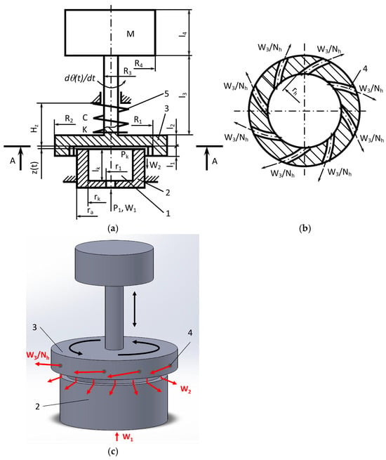
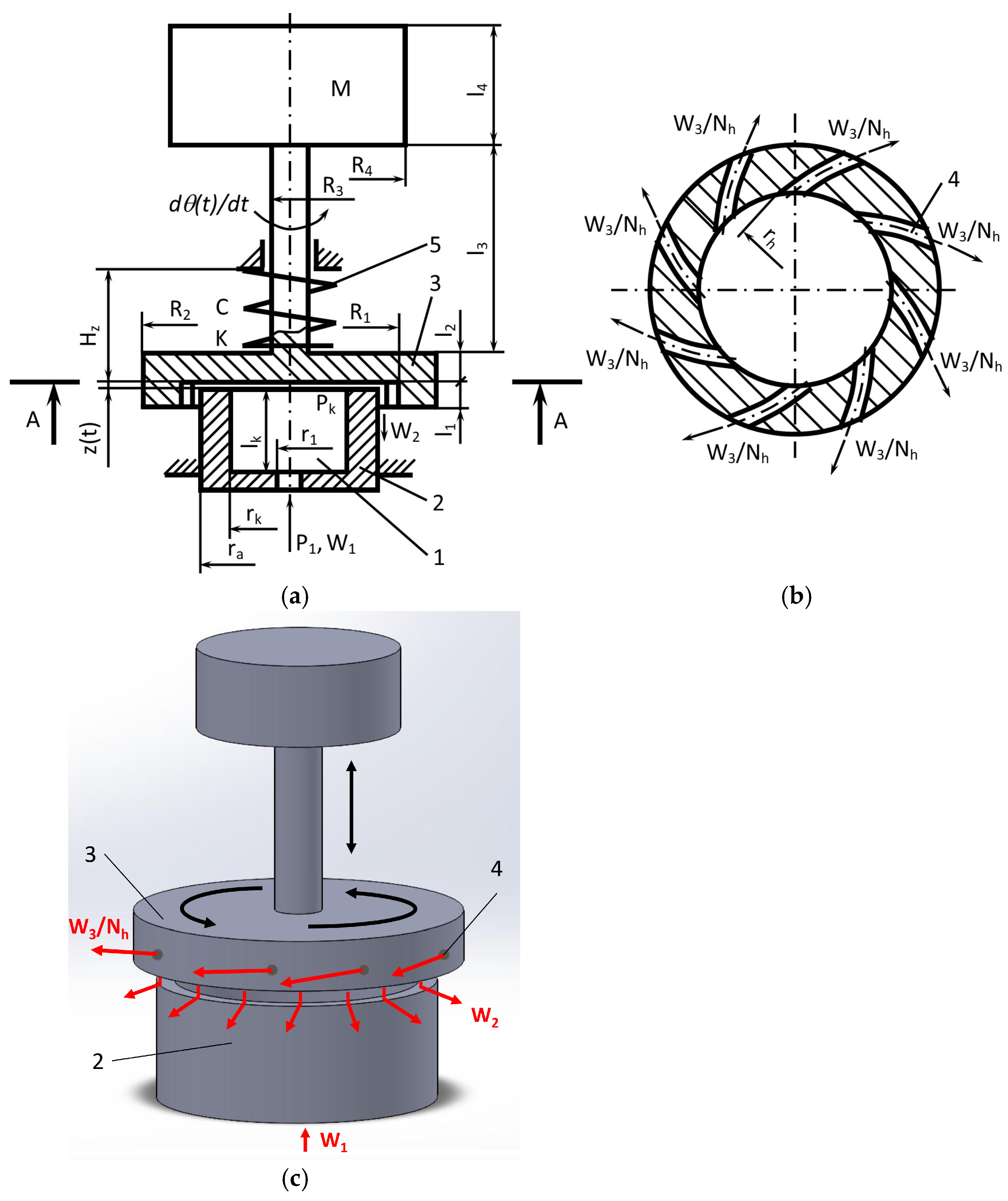
Figure 1 shows a diagram of a two-degree-of-freedom vibroactuator. In the proposed design, the housing performs a combined oscillating motion along the Y axis and rotational oscillations about one longitudinal axis. Thus, two degrees of freedom (oscillating and rotational) are generated in a single coaxial mechanical structure. The principle of the operation of such vibroactuators is as follows: after supplying compressed air (gas) of a certain pressure P1, it flows W1 through the throttle into the chamber (1) in the vibroactuator body (2). Part of the gas flows W2 through the annular gap between the vibroactuator cover (3) with the mass M and the surface of the vibrator body (2). Another part of the air flows W3 through the air outlet channels (4), forcing the vibroactuator cover to rotate. A static gas cushion is formed in the aforementioned gap. A further increase in the pressure of the gas flowing in the chamber increases the pressure in the chamber and in the gap until the elastic suspension (vibroactuator cover (3) with mass M is tightened by a spring (5)), overcoming the elasticity of the spring (5), begins to move towards an increase in the working gap. Due to the inertia of the vibroactuator cover (3) with the mass M, the suspension overcomes the equilibrium point, and the gap reaches its maximum value. In this position, the pressure in the chamber is too high, so less gas flows through the throttle than flows out through the gap and air outlet channels to the outside. As a result, the pressure in the chamber decreases. Then the cover of the vibroactuator with the mass begins to move in the direction of decreasing the working gap. Due to inertia, the equilibrium point is overcome again, and the gap reaches a minimum value.
Figure 1.
Calculation scheme for a two-degree-of-freedom pneumatic vibroactuator: (a) Side view; (b) Bottom view (A-A); (c) 3D view: 1—chamber; 2—body; 3—cover; 4—air outlet channels; 5—spring; ra = 15 × 10−3 m—vibroactuator body radius; rk = 10 × 10−3 m—chamber radius; lk = 20 × 10−3 m—chamber height; r1 = 1.5 × 10⁻³ m—radius of the compressed air supply channel; rh = (0.5, 1.0, 2.0, 3.0) × 10−3 m—radius of the air outlet from the chamber channel end; R1 = 15.5 × 10⁻³ m—radius of the lid chamber (inner cylinder radius); l1 = 11 × 10−3 m—height of the lid chamber; R2, R3, R4—outer cylinder radii; l2, l3, l4—heights of the cylinders forming the working body; P1—pressure of compressed air supplied to the chamber; W1—amount of air supplied; PK—air pressure in the chamber; W2—amount of air flowing out of the chamber; W3/Nh—amount of air outflowing through the hole in the lid; M—working mass; C—rigidity coefficient; K—damping coefficient; Hz—initial tightening of vibrating masses; z(t)—vertical displacement of the working body; dθ(t)/dt—angular velocity of the working body.
As the gap decreases, the gas accumulates in the chamber faster than it flows out through the gap and the air outlet channels, so the pressure increases again. The increased pressure forces the cover of the vibroactuator with the mass to move in the direction of increasing the gap. The process repeats cyclically.
The mathematical model describes a dynamic of a pneumo-mechanical system consisting of two coaxial cylinders with air flow. The system exhibits coupled vertical motion and rotation of the upper cylinder (lid) due to internal pressure and tangentially angled holes.
The entire system is described by two second-order differential equations that characterize the vertical (1) and rotational (2) motions of the actuating element:
where z(t)—vertical displacement of the working body; z(t)/dt—vertical velocity; PK(t)—internal pressure in chamber; P1—supply pressure (upstream); Hz—initial tightening of vibrating masses; Patm—ambient pressure; K—damping coefficient; C—rigidity coefficient; M—working mass; and g—gravitational acceleration.
where I—lid moment of inertia about Z axis, b—quadratic air resistance (typical b ≈ 0.0005), θ(t)—rotation angle of the lid about Z axis; dθ(t)/dt—angular velocity; Nh—number of holes (Nh = 8); Fhole is the impulse force from one hole, rmid—moment arm (equal to mean radius); and γ—the inclination of the hole with respect to the radial normal. The angle of inclination determines the tangential component of the moment and participates as a coefficient equal to sin γ.
According to the ideal gas law:
The pressure change or gas mass balance can be expressed as
where R—specific gas constant for air (287 J/kg·K); TK—supply temperature (assume that it is isothermal process and TK = 293 K); W1—amount of feeding air; W2—amount of air outflowing from chamber through the gap above the top; and W3—amount of air outflowing from through the 8 holes in the lid. The member ρK·dVK/dt takes into account the change in volume when the lid moves and the dependence of density on pressure.
The volume of the chamber and the space above the chamber is expressed by the following equation:
where rK—main chamber radius; lK—main chamber height; R1—lid chamber radius; and l1—lid chamber height.
The change in the volume of the chamber is expressed by the following equation:
The De Saint-Venant and Vantzel formulas with critical and subcritical modes are used to calculate air flows, which the authors have tested and whose effectiveness they have proven in previous studies [35].
Amount of feeding air:
Amount of air outflowing from the chamber through the gap above the top:
Amount of air outflowing through the holes in the lid:
where μi—coefficients assessing the gas resistance or discharge coefficients (typically 0.6–0.9); μ1—resistance coefficient of air entering into the chamber; μ2—resistance coefficient of air flow from the chamber; μ3—resistance coefficient of air flow from the holes in lid; ρ1—supplied air density; λ—critical ratio of pressures (λ = 0.528); β—ratio of specific heats (β = 1.405); and Sh—cross-sectional area of the air outlet.
Thus, the dynamics of this model can be described by a system of Equations (1), (2) and (4), which are used in the expressions Equations (6)–(9).
While solving the system of first- and second-degree differential equations, we transformed the system to first-degree equations. The Runge–Kutta method has been used to solve these equations. Differential equations are described in a matrix where members changing in time t are recalculated in separate procedures for each moment in time. The solution was realized using MATLAB R2025b software.
3. An Experimental Stand for the Study of a Pneumatic Vibroactuator
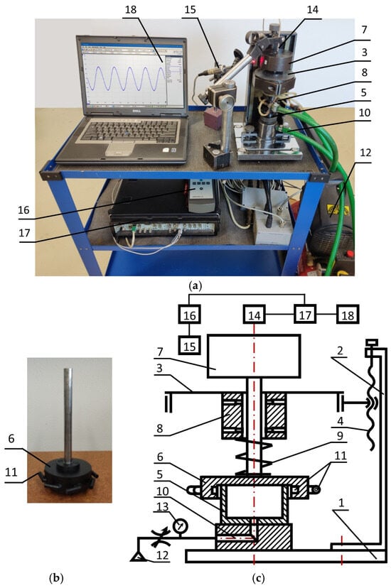
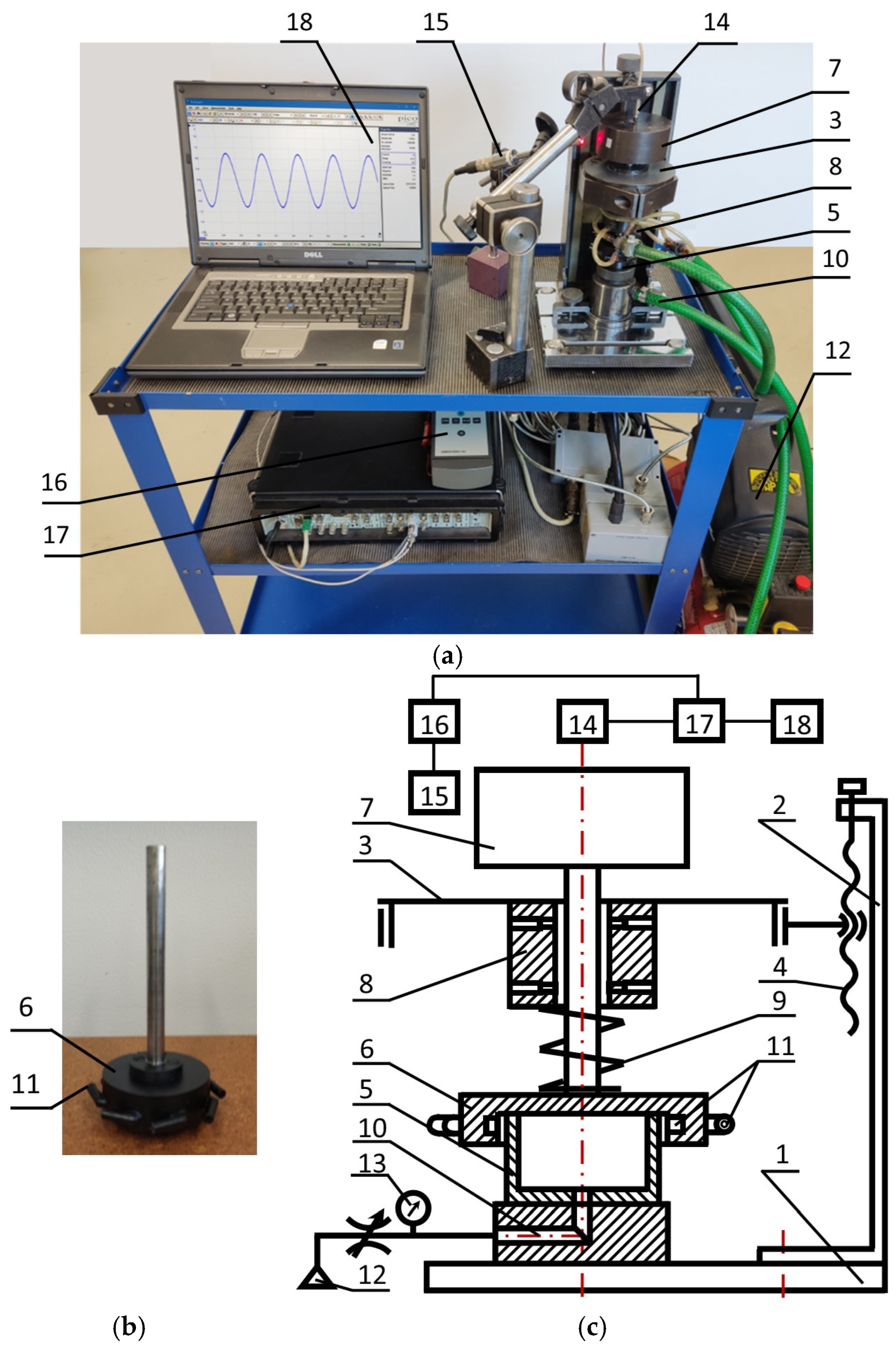
An experimental stand for the study of a two-degree-of-freedom pneumatic vibroactuator was installed. The general view and the structural scheme of the measuring equipment are presented in Figure 2. The output data of this multiparametric system (amplitude, frequency and angular velocity) depends on the value of the oscillatory changeable mass (7) and the geometrical parameters of chamber (5). The vibration parameters also depend on the cross-section area of the throttles (10) and amount of feeding pressure P1.
Figure 2.
Experimental stand for the research of pneumatic vibroactuator: (a) General view; (b) general view of cover with channels and (c) structural scheme: 1—base; 2—stand; 3—carrier; 4—screw; 5—vibroactuator body; 6—cover with channels; 7—changeable mass; 8—air bearing; 9—elastic spring; 10—air supply channel; 11—air outlet channels from the chamber; 12—compressed air system; 13—manometer; 14—non contact displacement sensor IN-081 (Brüel & Kjær); 15—angular velocity sensor P-95 (Brüel & Kjær); 16—analyser Vibrotest 60 (Brüel & Kjær); 17—PULSE 3560 analyzer (Brüel & Kjær); 18—computer.
During the experimental research, the following geometrical parameters of vibroactuator were used: rk = 10 × 10−3 m, lk = 20 × 10−3 m, r1 = 1.5 × 10⁻³ m, r1 = 15.5 × 10⁻³ m, l1 = 11 × 10−3 m, and rh = 1 × 10⁻³ m (Figure 1).
4. Results and Discussion
The digital solution for the mechanical system described above is based on the creation of mathematical models of the pneumatic self-oscillating vibroactuator described above, the numerical solution of the dynamic system, and a comparison of the results obtained with the results of the experimental research.
4.1. Results of the Investigation When the Initial Tightening Hz and the Supplied Pressure P1 Were Changed but the Work Mass M and Angle of the Cover Holes Relative to the Radial Normal γ Were Constant
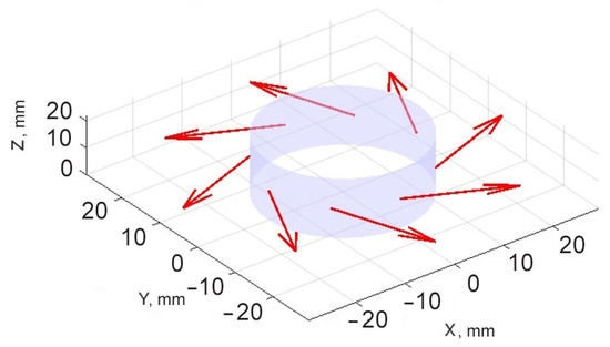
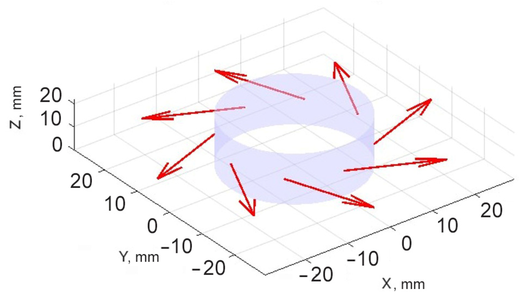
During the digital investigation, the initial tightening Hz, the supplied pressure P1, the work mass M, and the angle of the cover holes (Figure 3) relative to the radial normal γ were changed. The results of the calculations were compared with the experimental results obtained on the laboratory stand.
Figure 3.
Simplified 3D view of cover (lid) with angled holes: arrows present outflowing from lid.
The following initial geometric data and coefficients of the vibro-exciter were used for the calculations: rk = 10 × 10−3 m; lk = 20 × 10−3 m; ro = 1.5 × 10⁻³ m; r1 = 0.5 × 10⁻³ m; lk1 = 10 × 10−3 m; K = 38.2 kg/s; C = 14.7 N/mm; M = 1.45 kg, time t = [0; 2] s.
The values of the system parameters changed during modeling, and the obtained system vibration characteristics (amplitude A and frequency f) and rotational motion results (angle of rotation θ and angular velocity w) are presented in Table 2.
Table 2.
Initial data and results of the study according investigation 4.1.
The 1st column—number of the test; 2nd–4th—initial settings of the vibro-exciter; 5th–8th—characteristics of the working body vibrations and spindle rotation obtained by mathematical modeling; and 9th–10th—amplitudes of vibrations and values of frequencies obtained during the experiment.
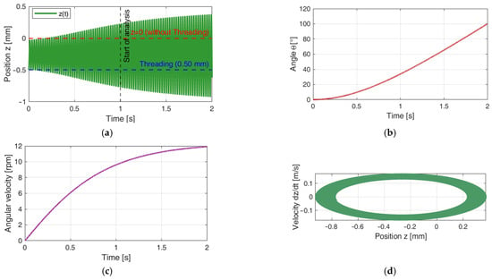
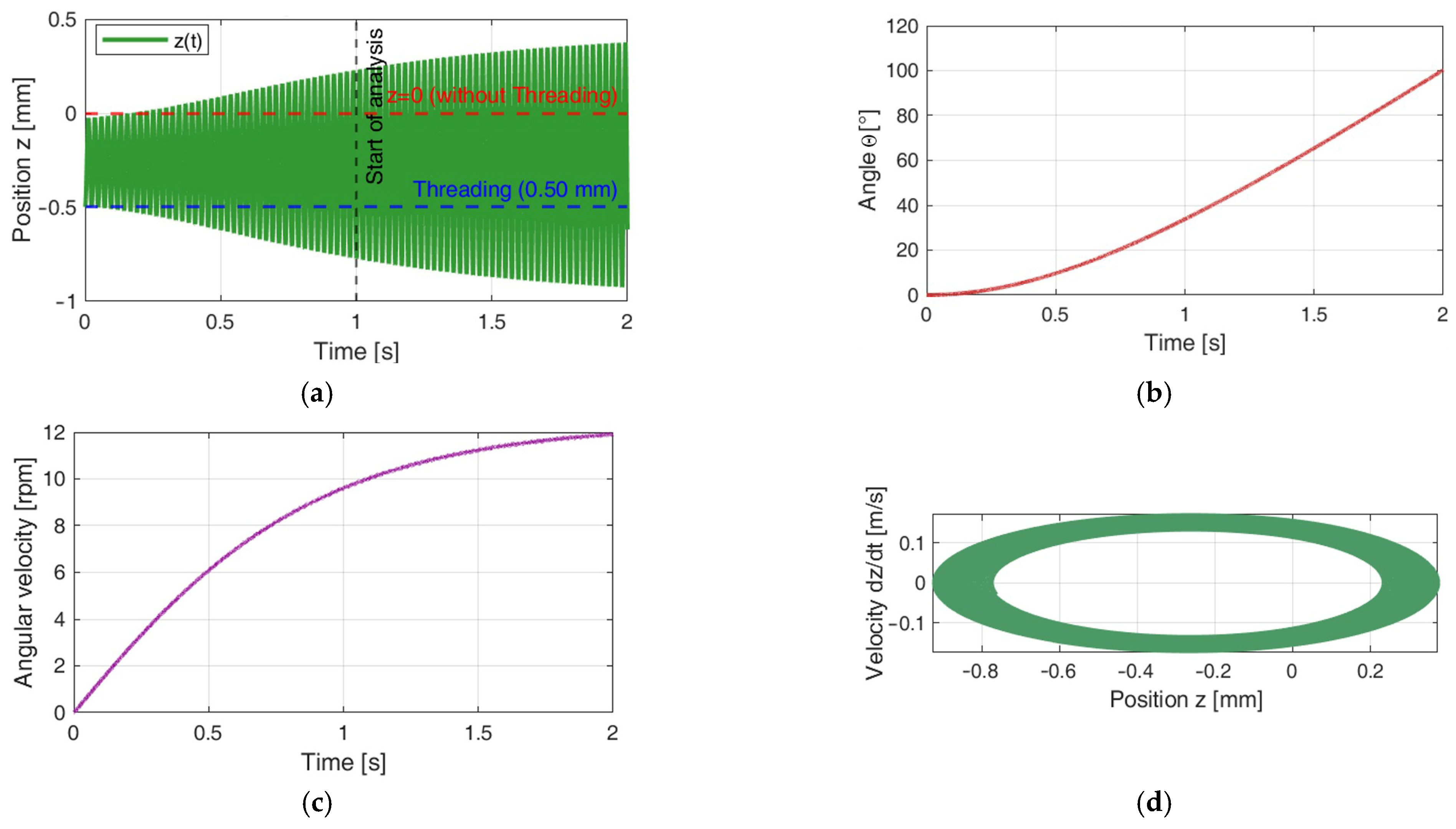
The characteristics of the variable parameters of the main mechanical systems obtained during the mathematical modeling are presented in Figure 4.
Figure 4.
Vibrations of working body of vibro-exciters (initial data from Table 1, Test No. 1): (a) vibrations z(t); (b) angle of rotation; (c) angular velocity; (d) phase view of system.
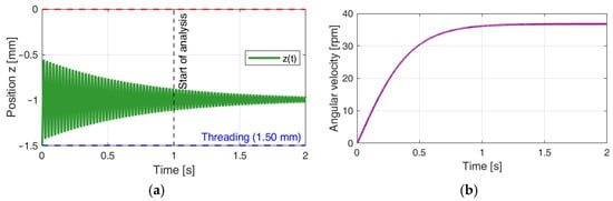
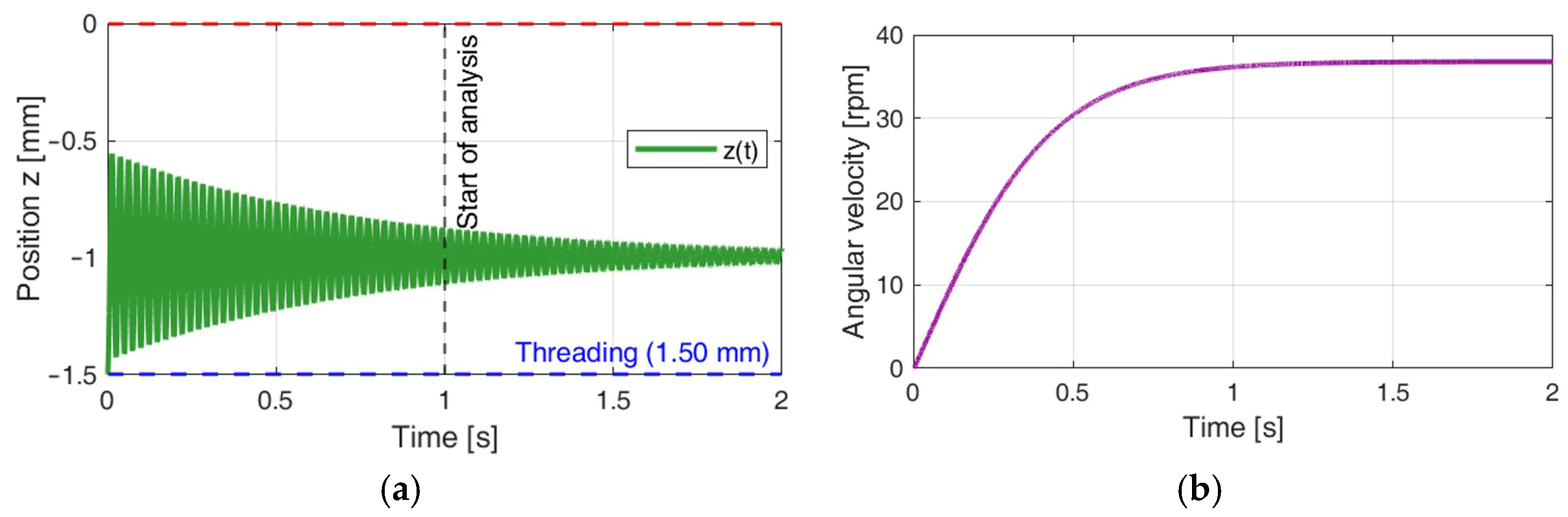
When the tightening Hz = 1.5 mm, attenuating vibrations were generated in the system, and the lid with a mass M reached a maximum angular velocity of w = 35 rpm on 0.75 s from the start and rotated at a constant speed (Test No. 7, Figure 5).
Figure 5.
Vibrations of working body of vibro-exciters (initial data from Table 1, Test No. 7): (a) vibrations z(t); (b) angular velocity.
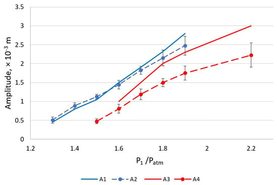
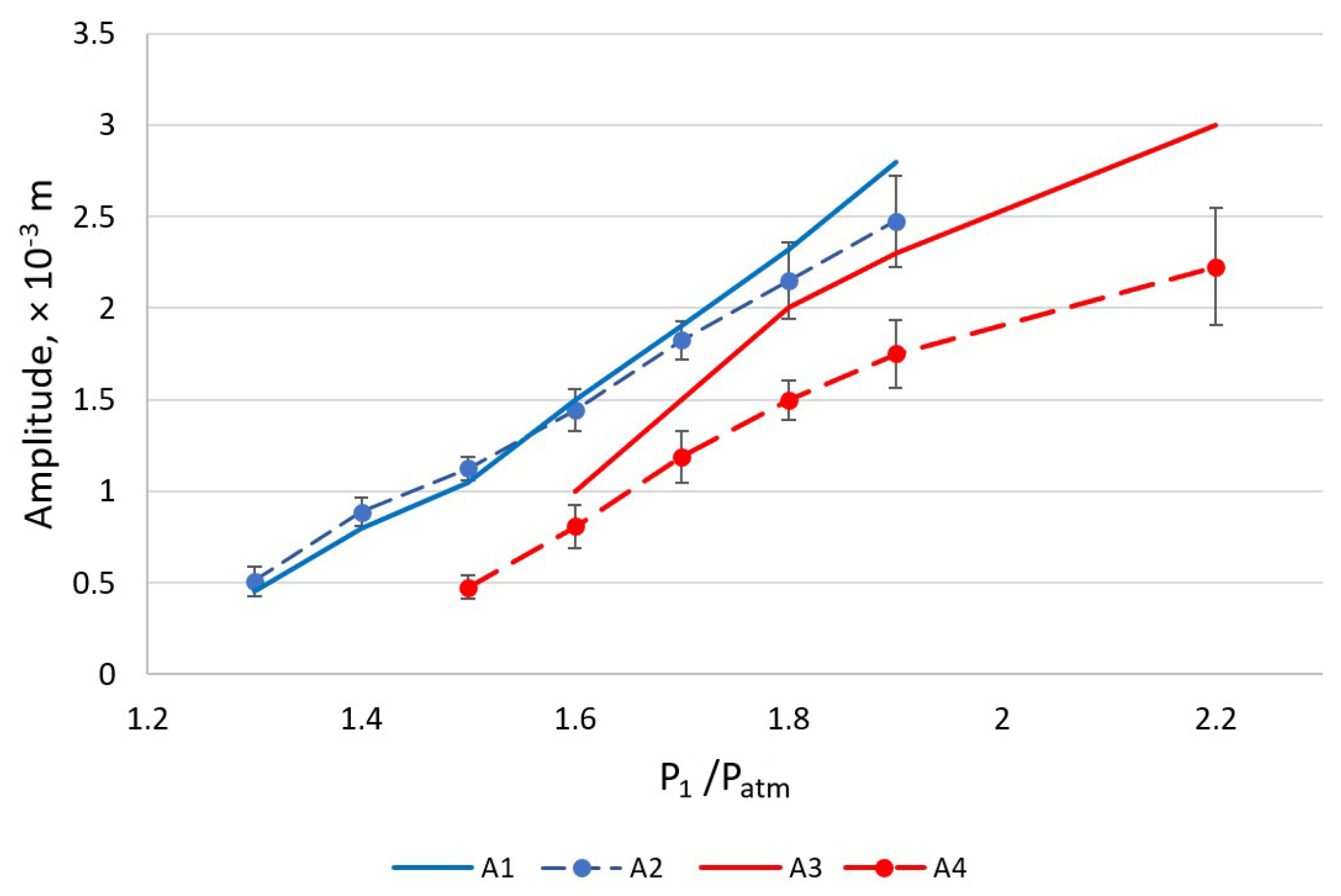
The analysis of the dependences of the vibration exciter amplitude on the supplied air pressure, presented in Figure 6, shows that at a lower initial stress (Hz = 0.5 × 10⁻³ m) the results of the theoretical model and the experiment agree well. This is confirmed by the correspondence of the blue curves (A1 and A2), which allows us to state that the selected model adequately describes the phenomenon under study in this case.
Figure 6.
Vibrations of working body of vibro-exciters: A1, A3 (solid lines)—results of mathematical calculations; A2, A4 (dashed lines)—results of experiments.
Meanwhile, at a higher initial stress (Hz = 1.0 × 10⁻³ m), the correspondence of the theoretical and experimental results is worse—the coincidence of the red curves (A3 and A4) can be assessed only as average. This may indicate that at higher stress, certain physical factors are not sufficiently evaluated by the model, for example, nonlinear effects or additional losses.
4.2. Results of the Investigation of the Angular Velocity on the Supplied Compressed Air Pressure
The dependence of the angular rotation speed (angular velocity) on the supplied compressed air pressure was investigated using mathematical modeling. A comparison of the results of the theoretical investigation with the experimental results is presented in Table 3.
Table 3.
Initial data and results of the study according investigation 4.2.
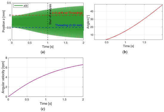
When the tightening Hz = 0.5 mm and supply pressure P1 = 1.3 × Patm, and the radius of the holes arranged at an angle in the cover rh = 0.5 × 10⁻³ m, self-vibrations were generated in the system with amplitude A = 0.36 × 10⁻³ m, and the lid with a mass M reached angular velocity of w = 6.6 rpm = 0.69 rad/s, as shown in Figure 7.
Figure 7.
Vibrations of the working body of vibro-exciters according to the data of Test No.1 from Table 2: (a) vibrations z(t); (b) angle of rotation; (c) angular velocity.
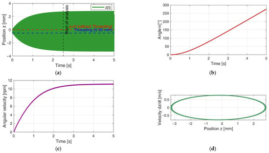
When the tightening Hz = 0.5 × 10⁻³ m and supply pressure P1 = 1.8 × Patm, self-vibrations were generated in the system with amplitude A = 2.25 × 10⁻³ m, and the lid with a mass M reached a maximum angular velocity value w = 11.2 rpm = 1.17 rad/s after 4.1 s, as shown in Figure 8.
Figure 8.
Vibrations of working body of vibro-exciters (initial data from Table 2, Test No. 3): (a) vibrations z(t); (b) angle of rotation; (c) angular velocity; (d) phase view of system.
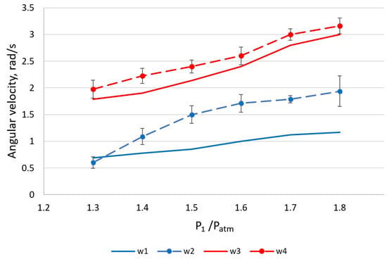
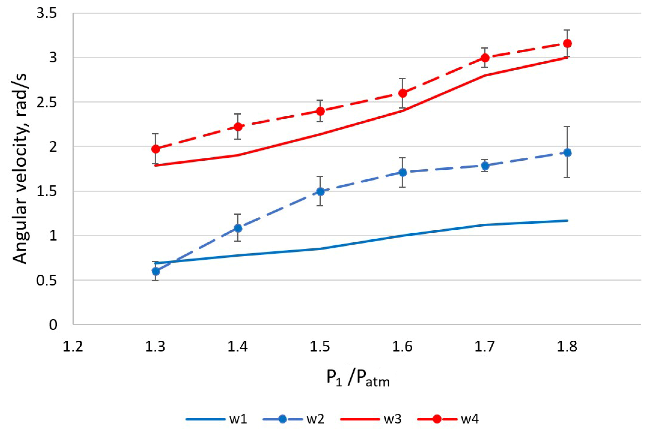
Figure 9 presents graphs of the dependence of the angular velocity on the supplied air pressure at different initial tightening Hz values. The dashed line marks the experimental results, while the solid line marks the theoretical results. Blue lines (w1 and w2) correspond to the results obtained when tightening Hz = 0.5 × 10⁻³ m, and red lines (w3 and w4) indicate when Hz = 1.0 × 10⁻³ m. It can be observed that doubling the initial stress causes the mathematical model to correlate less well with the experimental data, providing only an illustration of the trends in the influence of the parameters rather than accurate results. Since the initial excitation of the main working dynamic system was considered to be Hz = 0.5 × 10⁻³ m, the mathematical model focuses on this initial parameter.
Figure 9.
The dependence of the angular velocity on the supplied compressed air pressure at different tightening: w1, w3 (solid lines)—results of mathematical calculations; w2, w4 (dashed lines)—results of experiments.
4.3. Results of the Investigation of the Angular Velocity on the Supplied Compressed Air Pressure at Different Radii of the Air Outlet Channel in the Lid Wall
The dependence of the angular velocity on the supplied compressed air pressure at different radii of the air outlet channel in the lid wall is presented in Table 4. Mathematical modeling was performed using the following parameters: M = 1.45 kg, tightening Hz = 0.5 × 10⁻³ m, γ = 15°. During the calculations, the value of the supplied pressure P1 and the radius of the hole in the cover wall rh were changed.
Table 4.
Initial testing data and results of the research.
The 1st column—number of the test; 2nd–3rd—initial changing settings of vibro-exciter; 4th–5th—spindle rotation obtained by mathematical modeling; 6th—values of angular velocity obtained during the experiment.
The results of mathematical modeling showed that increasing the diameter of the air outlet channels from 1.0 × 10⁻³ m to 2.0 × 10⁻³ m increased the angular velocity of rotation. When the channel diameter is increased to 4.0 × 10⁻³ m, no self-vibrations occur in the vibro-exciter, and the angular velocity decreases to 3.2 rpm.
The main characteristics of the pneumatic vibroactuator are presented in Table 5.
Table 5.
Main characteristics of pneumatic vibroactuator.
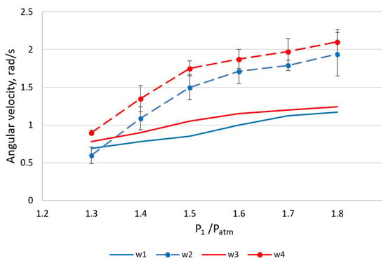
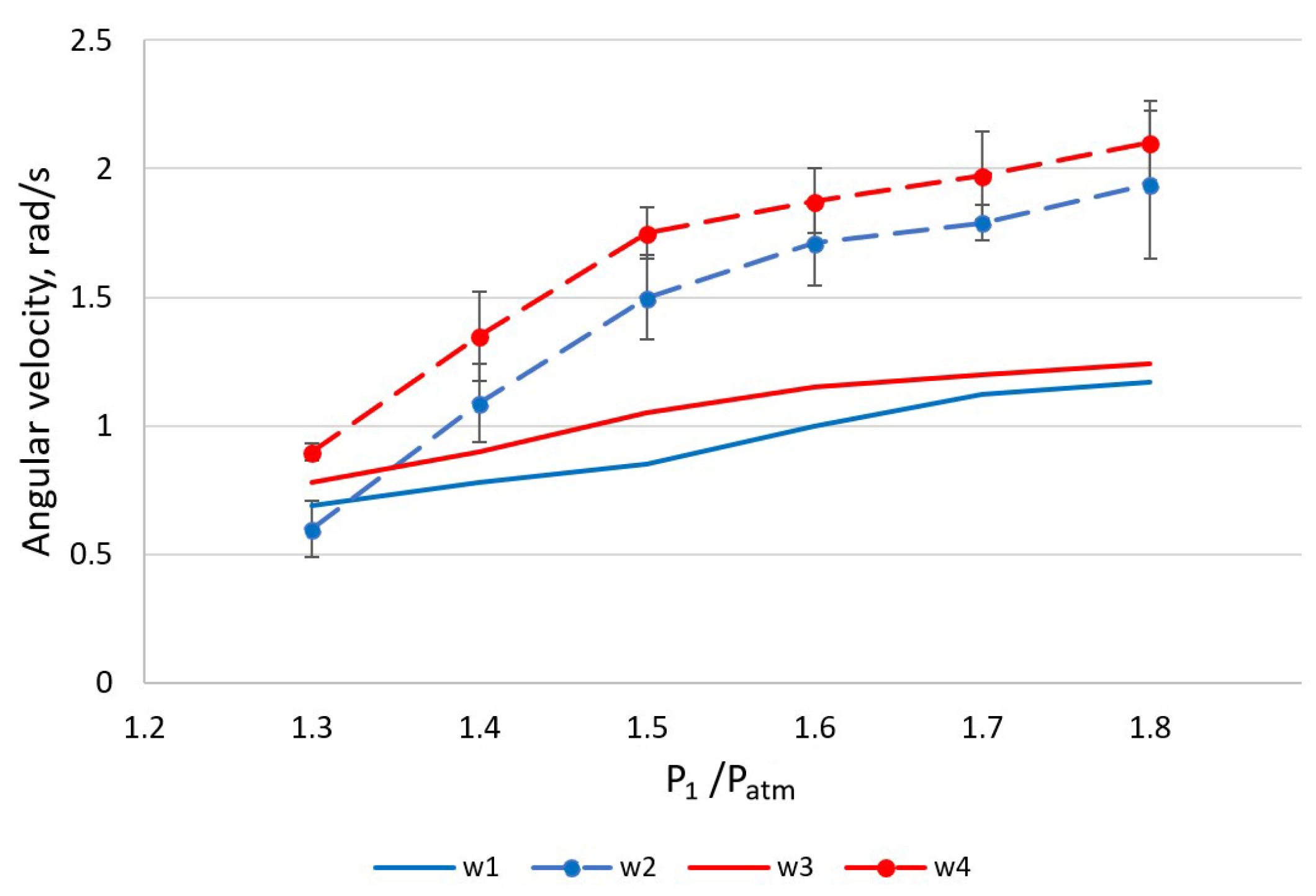
Figure 10 shows graphs of the dependence of angular velocity on the supplied air pressure. The dashed line marks the experimental results, while the solid line marks the theoretical results. Blue lines (w1 and w2) correspond to the results obtained when the diameter of the air outlet channels rh = 0.5 × 10⁻³ m, and red lines (w3 and w4) indicate when rh = 1.0 × 10⁻³ m.
Figure 10.
The dependence of the angular velocity on the supplied compressed air pressure at different diameter of the air outlet channels: w1, w3 (solid lines)—results of mathematical calculations; w2, w4 (dashed lines)—results of experiments.
5. Conclusions
A pneumatic vibro-exciter with a rotational working mass lid, operating in a regime of self-exciting vibrations, was investigated.
A mathematical model was created using De Saint-Venant and Vantzel equations that described the dynamics of the mechanical system of two types of movements of the pneumatic vibro-exciter. This model is a system of several first- and second-degree differential equations that was reduced to a system of first-degree equations and solved applying the Runge—Kutta method.
The experimental data and the results of the mathematical modeling of the vibro-exciter of the considered design correlate with each other. When analyzing the results, the same dependencies and trends in the movement of the working body are determined. The mathematical model is limited to isothermal conditions; therefore, discrepancies with the experiment are possible.
The amplitude of the vibro-exciter’s self-oscillations linearly depends on the supplied air pressure. Under certain mechanical and geometric parameters of the dynamic system, with a 1.5-fold increase in the air pressure supplied to the chamber, the vibro-exciter’s oscillation amplitude can increase by six times.
During the study, it was found that with these initial data, the system could operate in the self-oscillation mode when the supplied pressure varied from 1.3 to 2.2 × Patm.
Increasing the initial tightening, the occurrence of self-oscillations of the working body of the vibro-exciter occurred at a higher supplied pressure. By increasing the initial tightening from 0.5 to 1.0 × 10⁻³ m, the system entered the auto-oscillation mode at approximately 1.2 times the applied pressure (instead of 1.3 × Patm, 1.52 × Patm was required).
By increasing the tightening more than 1.5 × 10⁻³ m, auto-oscillations were not achieved at any applied pressure values during the mathematical study.
Increasing the air supplied to the chamber linearly changed the results of the angular velocity of the working body. By increasing the pressure from 1.3 to 1.8 × Patm, the angular velocity increased to 1.6 times.
Theoretical studies show that the angular velocity also linearly depends on the diameter of the air outlet holes in the cover. However, if the diameter is increased too much, without changing other geometric parameters of the vibro-actuator, auto-oscillations of the working body no longer occur.
For further research, the authors plan to conduct an experiment with a vibro-exciter with other geometric parameters and supplement the theoretical study with simulation analysis in a MATLAB Simulink environment.
Author Contributions
Conceptualization, K.V.; methodology, K.V. and D.P.; software, D.P.; validation, D.P., L.G. and I.V.; formal analysis, L.G. and I.V.; investigation, D.P., L.G. and I.V.; resources, L.G. and I.V.; writing—original draft preparation, L.G. and I.V.; writing—review and editing, K.V. and D.P.; supervision, K.V. All authors have read and agreed to the published version of the manuscript.
Funding
This research received no external funding.
Institutional Review Board Statement
Not applicable.
Informed Consent Statement
Not applicable.
Data Availability Statement
The data that support the findings of this research are available from the corresponding authors upon reasonable request.
Conflicts of Interest
The authors declare no conflicts of interest.
References
- Polizzi, M.A.; Franchville, J.; Hilden, J.L. Assessment and predictive modeling of pharmaceutical powder flow behavior in small-scale hoppers. Powder Technol. 2016, 294, 30–42. [Google Scholar] [CrossRef] [Scilit]
- Wiesner, V.L.; Rueschhoff, L.M.; Diaz-Cano, A.I.; Trice, R.W.; Youngblood, J.P. Producing dense zirconium diboride components by room-temperature injection molding of aqueous ceramic suspensions. Ceram. Int. 2016, 42, 2750–2760. [Google Scholar] [CrossRef] [Scilit]
- Zhang, J.; Chaudhari, A.; Wang, H. Surface quality and material removal in magnetic abrasive finishing of selective laser melted 316L stainless steel. J. Manuf. Process. 2019, 45, 710–719. [Google Scholar] [CrossRef] [Scilit]
- Abbas, S.; Faisal, A.; Khan, M.A.; Nehdi, M.L.; Hameed, R.; Shaukat, S. Systematic state-of-the-art review on precast concrete pipes. RINENG 2025, 25, 103826. [Google Scholar] [CrossRef] [Scilit]
- Saleem, S.; Shah, O.H.; Jirawattanasomkul, T.; Dawei, Z.; Pimanmas, A.; Kunawisarut, A.; Srivaranun, S. Evaluating natural and synthetic fibers in strengthening concrete column specimens with varying corner radii and aspect ratios. J. Build. Eng. 2025, 103, 112095. [Google Scholar] [CrossRef] [Scilit]
- Angelastro, A.; Campanelli, S.L.; Casalino, G. Statistical analysis and optimization of direct metal laser deposition of 227-F Colmonoy nickel alloy. Opt. Laser Technol. 2017, 94, 138–145. [Google Scholar] [CrossRef] [Scilit]
- Khalkhali, Z.; Rothstein, J.P. Characterization of the cold spray deposition of a wide variety of polymeric powders. Surf. Coat. Technol. 2020, 383, 125251. [Google Scholar] [CrossRef] [Scilit]
- Rajan, K.S.; Rothstein, J.P. Cold spray deposition of high density polyethylene composite powders. Surf. Coat. Technol. 2024, 484, 130809. [Google Scholar] [CrossRef] [Scilit]
- Hartig, J.; Howard, H.C.; Stelmach, T.J.; Weimer, A.W. DEM modeling of fine powder convection in a continuous vibrating bed reactor. Powder Technol. 2021, 386, 209–220. [Google Scholar] [CrossRef] [Scilit]
- Chabannes, M.; Becquart, F.; Garcia-Diaz, E.; Abriak, N.E.; Clerc, L. Experimental investigation of the shear behaviour of hemp and rice husk-based concretes using triaxial compression. Constr. Build. Mater. 2017, 143, 621–632. [Google Scholar] [CrossRef] [Scilit]
- Frost, J.D.; Roy, N.; Chen, C.-C.; Park, J.-Y.; Jang, D.-J.; Lu, Y.; Cao, J. Quantitative Analysis of Microstructure Properties and their Influence on Macroscale Response. KSCE J. Civ. Eng. 2019, 23, 3777–3792. [Google Scholar] [CrossRef] [Scilit]
- Ibagón, L.; Caicedo, B.; Villacreses, J.P.; López-Caballero, F. Mitigating washboard effect: A study on geocells as soil reinforcement for unpaved roads. Geotext. Geomembr. 2025, 53, 1433–1445. [Google Scholar] [CrossRef] [Scilit]
- Lohar, J.; Shrivastava, N. Granite processing waste as sustainable structural fill in reinforced soil structures: A techno-economic analysis. Constr. Build. Mater. 2025, 491, 142800. [Google Scholar] [CrossRef] [Scilit]
- Kommanamanchi, V.; Chennarapu, H.; Balunaini, U. Mechanistic evaluation of biaxial and triaxial geogrids and geocells reinforcing C&D waste aggregate layers for sustainable flexible pavements. Constr. Build. Mater. 2025, 497, 143867. [Google Scholar] [CrossRef] [Scilit]
- Skonieczny, K.; Niksirat, P.; Forough Nassiraei, A.A. Rapid automated soil preparation for testing planetary rover-soil interactions aboard reduced-gravity aircraft. J. Terramech. 2019, 83, 35–44. [Google Scholar] [CrossRef] [Scilit]
- Comminal, R.; da Silva, W.R.L.; Andersen, T.J.; Stang, H.; Spangenberg, J. Modelling of 3D concrete printing based on computational fluid dynamics. Cem. Concr. Res. 2020, 138, 106256. [Google Scholar] [CrossRef] [Scilit]
- Sterren, A.F.; Cisterna, G.A.; Rustán, J.J.; Vaccari, N.E.; Balseiro, D.; Ezpeleta, M.; Prestianni, C. New invertebrate peri-glacial faunal assemblages in the Agua de Lucho Formation, Río Blanco Basin, Argentina. The most complete marine fossil record of the early Mississippian in South America. J. South Am. Earth Sci. 2021, 106, 103078. [Google Scholar] [CrossRef] [Scilit]
- Chatzikonstantinou, K.; Tzamtzis, N.; Pappa, A.; Liodakis, S. Membrane fouling control using high-frequency power vibration, in an SMBR pilot system—Preliminary studies. Desalination Water Treat. 2016, 57, 11550–11560. [Google Scholar] [CrossRef] [Scilit]
- Ly, A.; Achouri, I.E.; Gosselin, R.; Abatzoglou, N. Sequential fixed-fluidized bed foam granulation (SFFBFG) and drying: Multivariate model development for water content monitoring with near–infrared spectroscopy. Chem. Eng. Sci. 2022, 262, 118039. [Google Scholar] [CrossRef] [Scilit]
- Bekaert, B.; Van Snick, B.; Pandelaere, K.; Dhondt, J.; Di Pretoro, G.; de Beer, T.; Vervaet, C.; Vanhoorne, V. Continuous direct compression: Development of an empirical predictive model and challenges regarding PAT implementation. Int. J. Pharm. X 2022, 4, 100110. [Google Scholar] [CrossRef] [Scilit]
- Matsunami, K.; Ryckaert, A.; Verrecas, H.; da Silva, A.F.T.; Anderson, A.; Wikström, H.; Dumarey, M.; Mann, J.; de Beer, T.; Vanhoorne, V.; et al. Comparative analysis of tablet dissolution behavior: Batch vs. Continuous direct compression. Int. J. Pharm. 2025, 675, 125498. [Google Scholar] [CrossRef] [Scilit] [PubMed]
- Kitselis, A.; Traiforos, N.A.; Manolakos, D.E. The effect of resonance on the void content in CFRP tubes. Compos. B Eng. 2016, 106, 164–171. [Google Scholar] [CrossRef] [Scilit]
- Li, Z.; Si, Q.; Jia, P.; Xiao, G.; Tong, X. Research on particle swarm screening mechanism and performance optimization based on simulated lunar microgravity. Adv. Space Res. 2024, 73, 2137–2154. [Google Scholar] [CrossRef] [Scilit]
- Dalton, B.H.; Contento, V.S.; Power, G.A. Residual force enhancement during submaximal and maximal effort contractions of the plantar flexors across knee angle. J. Biomech. 2018, 78, 70–76. [Google Scholar] [CrossRef] [Scilit]
- Botter, A.; Cerone, G.L.; Saggini, R.; Massazza, G.; Minetto, M.A. Characterization of the stimulation output of four devices for focal muscle vibration. Med. Eng. Phys. 2020, 85, 97–103. [Google Scholar] [CrossRef] [Scilit]
- Landelle, C.; Anton, J.-L.; Nazarian, B.; Sein, J.; Gharbi, A.; Felician, O.; Kavounoudias, A. Functional brain changes in the elderly for the perception of hand movements: A greater impairment occurs in proprioception than touch. NeuroImage 2020, 220, 117056. [Google Scholar] [CrossRef] [Scilit]
- Li, K.; Cai, W.; Zhao, B.; Lu, B.; Li, S.; Ni, X. Simulation and experimental study on the seed filling performance of a split cotton seeder. Biosyst. Eng. 2025, 253, 104128. [Google Scholar] [CrossRef] [Scilit]
- Rezich, E.; Butt, G.; Aubin-Fournier, P.-L.; Skonieczny, K.; Haskin, I.; Nguyen, Q.G. Effect of reduced gravity on tool forces of an ultrasonically vibrating blade in regolith simulant. Acta Astronaut. 2025, 236, 1272–1286. [Google Scholar] [CrossRef] [Scilit]
- Qiu, Z.; Zhao, Z. Vibration suppression of a pneumatic drive flexible manipulator using adaptive phase adjusting controller. J. Vib. Control 2015, 21, 2959–2980. [Google Scholar] [CrossRef] [Scilit]
- Gao, H.; De Volder, M.; Cheng, T.; Bao, G.; Reynaerts, D. A pneumatic actuator based on vibration friction reduction with bending/longitudinal vibration mode. Actuator A-Phys. 2016, 252, 112–119. [Google Scholar] [CrossRef] [Scilit]
- Morales, A.L.; Nieto, A.J.; Chicharro, J.M.; Pintado, P. An adaptive pneumatic system for the attenuation of random vibrations. J. Vib. Control 2015, 21, 907–918. [Google Scholar] [CrossRef] [Scilit]
- Liang, J.; Chen, H.; Wu, Q. Active suppression of pneumatic vibration isolators using adaptive sliding controller with self-tuning fuzzy compensation. J. Vib. Control 2015, 21, 246–259. [Google Scholar] [CrossRef] [Scilit]
- Khajepour, A. Nonlinear controller design for asymmetric actuators. J. Vib. Control 2000, 6, 937–959. [Google Scholar] [CrossRef] [Scilit]
- Zhao, Z.; Qiu, Z.; Zhang, X.; Han, J. Vibration control of a pneumatic driven piezoelectric flexible manipulator using self-organizing map based multiple models. Mech. Syst. Signal Process. 2016, 70–71, 345–372. [Google Scholar] [CrossRef] [Scilit]
- Kibirkštis, E.; Pauliukaitis, D.; Vaitasius, K.; Gegeckienė, L.; Venytė, I.; Jurėnas, V. Research of Multi-Mode Pneumatic Vibroactuator. Actuators 2023, 12, 348. [Google Scholar] [CrossRef] [Scilit]
- da Silva, J.A.I.; Marques, F.D. Multi-degree of freedom nonlinear energy sinks for passive control of vortex-induced vibrations in a sprung cylinder. Acta Mech. 2021, 232, 3917–3937. [Google Scholar] [CrossRef] [Scilit]
- Ahmad, M.M.; Khan, N.M.; Khan, F.U. Multi-degrees of freedom energy harvesting for broad-band vibration frequency range: A review. Sens. Actuators A Phys. 2022, 344, 113690. [Google Scholar] [CrossRef] [Scilit]
- Ordoñez, V.; Arcos, R.; Romeu, J.; Reina, S. Analysis of Different Cylindrical Magnet and Coil Configurations for Electromagnetic Vibration Energy Harvesters. PEN 2021, 9, 1055–1063. [Google Scholar] [CrossRef] [Scilit]
- Liu, C.; Zhao, R.; Yu, K.; Lee, H.P.; Liao, B. A quasi-zero-stiffness device capable of vibration isolation and energy harvesting using piezoelectric buckled beams. Energy 2021, 233, 121146. [Google Scholar] [CrossRef] [Scilit]
- Salem, M.S.; Ahmed, S.; Shaker, A.; Alshammari, M.T.; Al-Dhlan, K.A.; Alanazi, A.; Saeed, A.; Abouelatta, M. Bandwidth Broadening of Piezoelectric Energy Harvesters Using Arrays of a Proposed Piezoelectric Cantilever Structure. Micromachines 2021, 12, 973. [Google Scholar] [CrossRef] [Scilit]
- Zorlu, Ö.; Topal, E.T.; Külah, H.A. Vibration-Based Electromagnetic Energy Harvester Using Mechanical Frequency Up-Conversion Method. IEEE Sens. J. 2011, 11, 481–488. [Google Scholar] [CrossRef] [Scilit]
- Liang, H.; Hao, G.; Olszewski, O.Z. A review on vibration-based piezoelectric energy harvesting from the aspect of compliant mechanisms. Sens. Actuators A Phys. 2021, 331, 112743. [Google Scholar] [CrossRef] [Scilit]
- Shabanalinezhad, H.; Svelto, C.; Malcovati, P.; Gatti, G. Design of a Two-Degree-of-Freedom Mechanical Oscillator for Multidirectional Vibration Energy Harvesting to Power Wireless Sensor Nodes. Sensors 2024, 24, 4531. [Google Scholar] [CrossRef] [Scilit]
- Pantelous, A.A.; Pirrotta, A. Modal Analysis of Multi-Degrees-of-Freedom Systems with Singular Matrices: Analytical Dynamics Approach. J. Eng. Mech. 2017, 143, 04021031. [Google Scholar] [CrossRef] [Scilit]
- Alaneme, G.U.; Bahrami, A.; Ibe Iro, U.; Ganasen, N.; Out, O.N.; Udeala, R.C.; Ifebude, B.O.; Onwusereaka, E.A. Numerical Analysis and Parametric Study on Multiple Degrees-of-Freedom Frames. Civ. Eng. J. 2023, 9, 1709–1736. [Google Scholar] [CrossRef] [Scilit]
- Yang, J.; Zhang, G.; Wang, L.; Wang, J.; Wang, H. Multi-degree-of-freedom joint nonlinear motion control with considering the friction effect. In Proceedings of the IEEE 19th World Symposium on Applied Machine Intelligence and Informatics (SAMI 2021), Herlany, Slovakia, 21–23 January 2021; pp. 000211–000216. [Google Scholar] [CrossRef] [Scilit]
- Zaghloul, A.; Bone, G.M. Origami-Inspired Soft Pneumatic Actuators: Generalization and Design Optimization. Actuators 2023, 12, 72. [Google Scholar] [CrossRef] [Scilit]
- Zhu, M.; Chen, S.; Xu, Z.; Dong, X. Design of Two-Degree-of-Freedom Fractional-Order Internal Model Control Algorithm for Pneumatic Control Valves. Actuators 2023, 12, 214. [Google Scholar] [CrossRef] [Scilit]
- Huang, Q.; He, G.; Feng, G.; Ding, B. A Novel Cooperative Control Strategy for Three-Degree-of-Freedom Pneumatic Parallel Mechanism. Actuators 2024, 13, 89. [Google Scholar] [CrossRef] [Scilit]
- Pustavrh, J.; Hočevar, M.; Podržaj, P.; Trajkovski, A.; Majdič, F. Comparison of hydraulic, pneumatic and electric linear actuation systems. Sci. Rep. 2023, 13, 20938. [Google Scholar] [CrossRef] [Scilit] [PubMed]

Disclaimer/Publisher’s Note: The statements, opinions and data contained in all publications are solely those of the individual author(s) and contributor(s) and not of MDPI and/or the editor(s). MDPI and/or the editor(s) disclaim responsibility for any injury to people or property resulting from any ideas, methods, instructions or products referred to in the content. |
© 2026 by the authors. Licensee MDPI, Basel, Switzerland. This article is an open access article distributed under the terms and conditions of the Creative Commons Attribution (CC BY) license.