Article

4-DOF Full-Speed Range Vibration Suppression of an Active–Passive Supported Flywheel Rotor Based on Inverse System Decoupling

1
School of Aeronautics and Astronautics, Sun Yat-sen University, Shenzhen 518107, China
2
School of Engineering and Design, Hunan Normal University, Changsha 410081, China
*
Author to whom correspondence should be addressed.
Actuators 2026, 15(3), 157; https://doi.org/10.3390/act15030157
Submission received: 28 January 2026 / Revised: 4 March 2026 / Accepted: 6 March 2026 / Published: 8 March 2026
(This article belongs to the Special Issue Vibration Control Based on Intelligent Actuators and Sensors)

Abstract

Flywheel energy storage systems exhibit superior performance in electric vehicle regenerative braking, railway traction power supply, and grid frequency regulation due to their high instantaneous power and fast dynamic response. However, systems supported by conventional mechanical bearings face severe radial structural coupling; unbalanced excitation and gyroscopic effects drastically amplify vibrations during critical speed traversal, undermining operational reliability and engineering scalability. To tackle this challenge, this paper proposes a full-speed vibration suppression scheme for active–passive supported flywheel energy storage systems integrated with a damping ring, combined with an inverse system decoupling controller to eliminate structural coupling, unbalance-induced vibration, and gyroscopic effects. A dynamic model of the integrated system is established using Lagrange’s equations, and four-degree of freedom decoupling expressions are derived to achieve complete radial decoupling. A speed-stage-based control strategy is further developed for full-speed adaptation. Comprehensive simulations validate the scheme’s decoupling performance, vibration suppression efficacy, and robustness. Results demonstrate that the proposed controller achieves full radial decoupling, reducing the average steady-state tracking error by 99.86%. The segmented control enables stable operation across 100–20,000 rpm and cuts critical speed resonance peaks by 81.23%. Compared with pure mechanical and magnetic bearing systems, the integrated active–passive support reduces resonance peaks by 94.72% and 42.25%, respectively. Under current perturbation and parameter variation, the scheme reduces the average steady-state error by 75.89% relative to the coupled system, confirming its strong engineering applicability.

1. Introduction

The frequent start–stop and braking of electric vehicles under urban conditions cause the power battery to be subjected to severe power fluctuations, accelerating battery degradation and shortening its service life [1,2,3]. Flywheel energy storage systems (FESSs), with their advantages of high instantaneous power, rapid response capability, and long cycle life, can efficiently recover braking energy and smooth out power fluctuations, becoming a key auxiliary energy storage unit for extending the life of power batteries. They have shown broad application prospects in fields such as electric vehicles, railway traction power supply, and grid frequency regulation [4,5,6]. As the core supporting component of FESSs, the performance of bearings directly determines the self-discharge rate, service life, maintenance cost, and operational stability of the system [7,8]. At present, mechanical bearings are widely used in vehicle-mounted FESSs due to their strong shock resistance to adapt to complex road conditions [9]. However, the traditional FESS of mechanical bearings has three core pain points. First, there is severe structural coupling in the radial direction, which leads to mutual interference of vibrations in each degree of freedom. Second, during full-speed operation, it is necessary to cross the critical speed. Unbalanced excitation causes resonance and intensifies vibration. Thirdly, the gyroscopic effect is significant under high-speed rotation, which is prone to cause dynamic instability and further deteriorate the dynamic performance of the system [10]. These problems jointly lead to accelerated bearing wear and excessive system vibration, seriously restricting the reliability and engineering application scope of FESS.
To solve the above problems, the active and passive support technology has become a research hotspot. By providing the basic load-bearing capacity through mechanical bearings and combining the active control capability of active magnetic bearings (AMBs), both load-bearing reliability and vibration suppression accuracy can be balanced [11]. Meanwhile, the introduction of damping elements can further enhance the vibration reduction performance of the system. Therefore, constructing an active and passive support architecture with damping elements, combined with efficient decoupling control and full-speed range adaptation strategies, has become a key path to break through the performance bottleneck of traditional FESSs, which has significant theoretical research value and engineering application significance.
To address the vibration and lifespan issues of FESS of the mechanical bearing, researchers first started with passive damping optimization. For instance, reference [12] proposed introducing elastic support damping devices into mechanical bearings to reduce vibration. Reference [13] developed a passive damping device based on O-rings, which achieves vibration reduction by changing the overall stiffness and damping of the bearing, with significant cost-effectiveness. Reference [14] adopts a cast silicone rubber seat small rolling element bearing (REB) combined with passive magnetic unloading technology, effectively reducing the bearing load and self-discharge rate of the FESS. In addition, reference [15] proposed a technical solution of using viscoelastic materials as the external damping structure to address the issue of excessive rotor deflection amplitude at the resonant speed of the system due to insufficient damping performance of passive magnetic bearings (PMBs). Tao [16] established a dynamic model for the rotationally symmetric flexible strut (RSS) base and performed static, modal, and harmonic response analyses to optimize the tangential support plates using an equivalent static load method. Experimental modal validation confirmed that the critical frequency of the optimized base was successfully shifted away from the operating frequency range, thereby effectively suppressing resonance. This study provides a valuable reference for analyzing and improving the vibration characteristics of such gas turbine support bases. Nonetheless, such passive damping devices generally have the drawbacks of complex structure, poor convenience of installation and disassembly, and fixed and unadjustable damping values, making it difficult to meet the dynamic characteristic requirements of FESS full-speed range operation. For this reason, this paper directly adopts the damping ring (DR) structure proposed by the author in the previous research literature [17], integrates it into the active and passive support system, and takes advantage of the compact structure and adjustable damping of this DR to enhance the vibration-damping adaptability of the system.
As a fully passive magnetic suspension support scheme, PMBs feature prominent advantages of high operational reliability and zero energy consumption, and have received extensive attention and in-depth research in the field of high-speed rotating machinery such as FESSs. Filatov and Maslen [18] proposed a PMB design scheme suitable for FESSs, which provides an important technical reference for the realization of high-stiffness passive radial and axial support for FESSs. Fang [19] carried out the integrated design and dynamic analysis of PMBs and damping systems for the engineering application requirements of high-speed compressors, and revealed the key role of eddy current damping in the vibration suppression of magnetically suspended rotor systems. Vigliani [20] systematically investigated the power loss suppression strategies of PMBs through a combination of numerical modeling and experimental testing, and their latest research results confirmed that the operational power loss of PMBs can be significantly reduced by optimizing the axial offset of magnetic rings and the structural design of magnetic circuits. However, PMBs have three inherent technical limitations: first, there is a coupling restriction between their stiffness and load capacity, making it difficult to meet the application requirements of FESSs with large loads; second, the lack of active adjustment capability makes it impossible to adapt to the vibration suppression requirements of rotor speed changes and external disturbances; third, the damping characteristics are mainly realized by the eddy current effect, and it is difficult to independently regulate and optimize the stiffness and damping. Therefore, the hybrid support and active–passive cooperative support schemes of PMBs and AMBs have become an important technical path to balance the operational reliability and dynamic control performance of rotating machinery systems, and also provide an important background support and research starting point for this paper.
Active and passive support technology, by integrating the advantages of mechanical bearings and AMBs, has become an important direction for solving the performance bottleneck of FESSs [21]. References [22,23] indicate that the combination of AMBs and mechanical bearings can significantly reduce the axial load of mechanical bearings, decrease frictional losses, and enhance charging efficiency and service life. Reference [24] effectively optimizes the bearing load spectrum through the collaborative design of elastic bearing supports and AMBs, reduces the cost of on-board FESS, and extends its service life. However, this technology has core challenges: the introduction of AMBs makes the system exhibit strong multivariable coupling characteristics, and the nonlinearity of the electromagnetic force intensifies with the increase of current and displacement amplitudes, significantly increasing the control difficulty. Therefore, decoupling control becomes the prerequisite for high-precision control of active and passive support FESSs.
The existing decoupling control methods are mainly classified into three categories: cross-feedback decoupling, differential geometric decoupling, and inverse system decoupling. Cross-feedback decoupling is widely used in gyroscopic effect suppression due to its simple structure [25], but it can only achieve approximately linear decoupling of the two radial rotational degrees of freedom and cannot solve the complete coupling problem of radial 4-DOF, thus limiting the control accuracy. Differential geometry decoupling can achieve complete decoupling, but it requires complex and abstract coordinate transformations, with ambiguous physical meanings and high engineering implementation difficulty [26,27]. The decoupling of the inverse system does not require a complex coordinate transformation. Its physical meaning is clear, and it is easy to implement in engineering, gradually becoming a research hotspot. For example, reference [28] proposed an inverse system decoupling control strategy based on the improved simulated annealing genetic algorithm (ISAGA) to optimize the support vector machine (SVM), aiming to address the inherent nonlinearity and strong coupling issues among rotor displacement, rotational speed, and flux linkage in the composite squirrel-cage bearing induction motor (CCR-BIM). The results show that this strategy can effectively achieve the decoupling control of rotor displacement, rotational speed, and flux linkage coupling in CCR-BIM. Reference [29] proposed a sliding mode active interference suppression control strategy based on inverse system decoupling, effectively suppressing the unbalanced vibration caused by rotor eccentricity. Reference [30] proposed a hybrid decoupling scheme of neural network inverse (NNI) and two-degree of freedom internal model control for the 4-DOF permanent magnet offset AMB system to compensate for the unmodeled dynamic effects. Reference [31] combines the inverse system with the internal model control and introduces phase advance compensation to address the stability and robustness issues brought about by the linearization of the current mode. Nonetheless, most of the existing research on decoupling the inverse system focuses on pure magnetic suspension rotor systems, without fully considering the differences in coupling characteristics brought about by the active and passive coordination of mechanical bearings and AMBs, making it difficult to be directly applied to active and passive support FESS with DR.
The cooperative control and full-speed range adaptation of the active and passive support systems is another research difficulty. Most of the existing research focuses on the co-optimization of vibration and friction losses: Reference [32] proposed the idea of joint control of vibration and friction in the active hybrid bearing rotor system, achieving co-optimization through differentiated controllers and neural network assisted computing. Reference [33] proposed a combined control scheme of vibration and friction for the active hybrid bearing (AHB) rotor system to ensure high precision and low loss operation. Reference [34] constructs a control system model with nonlinear hybrid bearings (ball bearings, squirrel-cage, electromagnetic actuators), providing a new path for the control of nonlinear rotating machinery. However, none of these studies have fully considered the impact of dynamic changes in rotational speed under full-speed range operation on cooperative control.
The core of full-speed range vibration control is to avoid critical speed resonance. Reference [35] proposed that by continuously adjusting the support stiffness to change the critical speed of the rotor, a resonance-free operation interval could be constructed, effectively reducing subcritical and supercritical responses. Reference [36] proposed a full-speed multi-damper control (FSMDC) strategy for the rotor system of aeroengines with elastic support dry friction dampers (ESDFDs) to ensure stable operation at critical speeds. Nevertheless, current full-speed range control strategies neither integrate the cooperative characteristics of active and passive supports nor are integrated with full decoupling control, thus failing to resolve the cooperative interference problem induced by coupling, dynamic changes in rotational speed, unbalanced, and gyroscopic effect. In conclusion, there are three core gaps in the existing research: passive damping devices cannot adapt to the dynamic characteristics of the full-speed range, and the research on active and passive support architectures with passive damping components is insufficient; inverse system decoupling is mostly applicable to pure magnetic suspension systems. It has not been designed for the coupling characteristics of active and passive support FESS with DR, making it difficult to achieve complete decoupling of 4-DOF. The full-speed range control is disconnected from the active and passive cooperative control and decoupling control, making it impossible to achieve stable vibration suppression throughout the entire operating range. To this end, this paper proposes a full-speed range vibration suppression scheme for FESSs with active and passive supports and DRs based on inverse system decoupling. Through the collaborative design of architecture innovation, decoupling optimization, and full-speed range adaptation, the above core problems are addressed.
This paper focuses on the full-speed range vibration suppression problem of active and passive support FESSs with DR, and conducts theoretical modeling, control strategy design, and simulation verification research. The primary contributions of this study are summarized as follows. First, this paper proposes a novel active–passive collaborative support architecture integrated with a DR. Through the design of the DR featuring “elastic support and replaceable filling material”, the architecture achieves “stable stiffness and adjustable damping”, addressing the poor adaptability of traditional passive damping devices. Meanwhile, it constructs a collaborative mechanism of “mechanical bearing load bearing-active magnetic bearing vibration control-DR energy dissipation”, thereby filling the research gap in the collaborative design between passive damping elements and active control in active–passive supports [15,17]. Second, this paper derives the inverse system 4-DOF decoupling expressions suitable for active–passive hybrid support systems. By real-time compensating for structural coupling forces and gyroscopic effect coupling forces, the strongly coupled system is decoupled into independent subsystems, breaking through the limitation that existing inverse system decoupling is only applicable to pure magnetic suspension systems [30,31]. Third, this paper establishes a full-speed segmented vibration suppression strategy covering “subcritical-critical-supercritical”stages. In the subcritical stage, decoupling and unbalance compensation are combined to suppress low-frequency vibrations; in the critical stage, continuous variable stiffness control is adopted to avoid resonance; and in the supercritical stage, decoupling is utilized to eliminate gyroscopic effects, filling the research gap that existing full-speed control is disconnected from decoupling and active–passive collaboration [35,36].
The subsequent sections of this paper are organized as follows. Section 2 is the theoretical basis and modeling, which elaborately introduces the overall structure of the active and passive support FESS and the structure and working principle of the DR, expounds the decoupling theory of the inverse system, establishes the system dynamics model based on the Lagrange equation, and deduces the 4-DOF decoupling expression. Section 3 is about the design of control strategies. Based on the characteristics of speed segmentation, a full-speed range vibration suppression controller with a decoupling module is designed, and the control parameters and switching logic for each speed range are clearly defined. Section 4 is simulation verification. Through multiple sets of simulation experiments, the decoupling characteristics of the system, the control effects in each speed domain, the operational stability in the full-speed domain, the active and passive cooperative performance, and the anti-interference robustness are analyzed. Section 5 is for discussion, analyzing the advantages and limitations of the proposed plan, and presenting future research directions. Section 6 is the conclusion, summarizing the core research achievements and innovative contributions of this paper.

2. Modeling of Active and Passive Supported FESSs and Inverse System Theory

Firstly, the structure of the FESS with active and passive supports and the design principle of the DR are introduced. Secondly, the dynamic equations of the FESS with active and passive supports are derived. Finally, the decoupling theory of the inverse system is expounded, and the expression after decoupling of the FESS with active and passive supports is derived.

2.1. Dynamic Modeling of FESSs with Active and Passive Supports

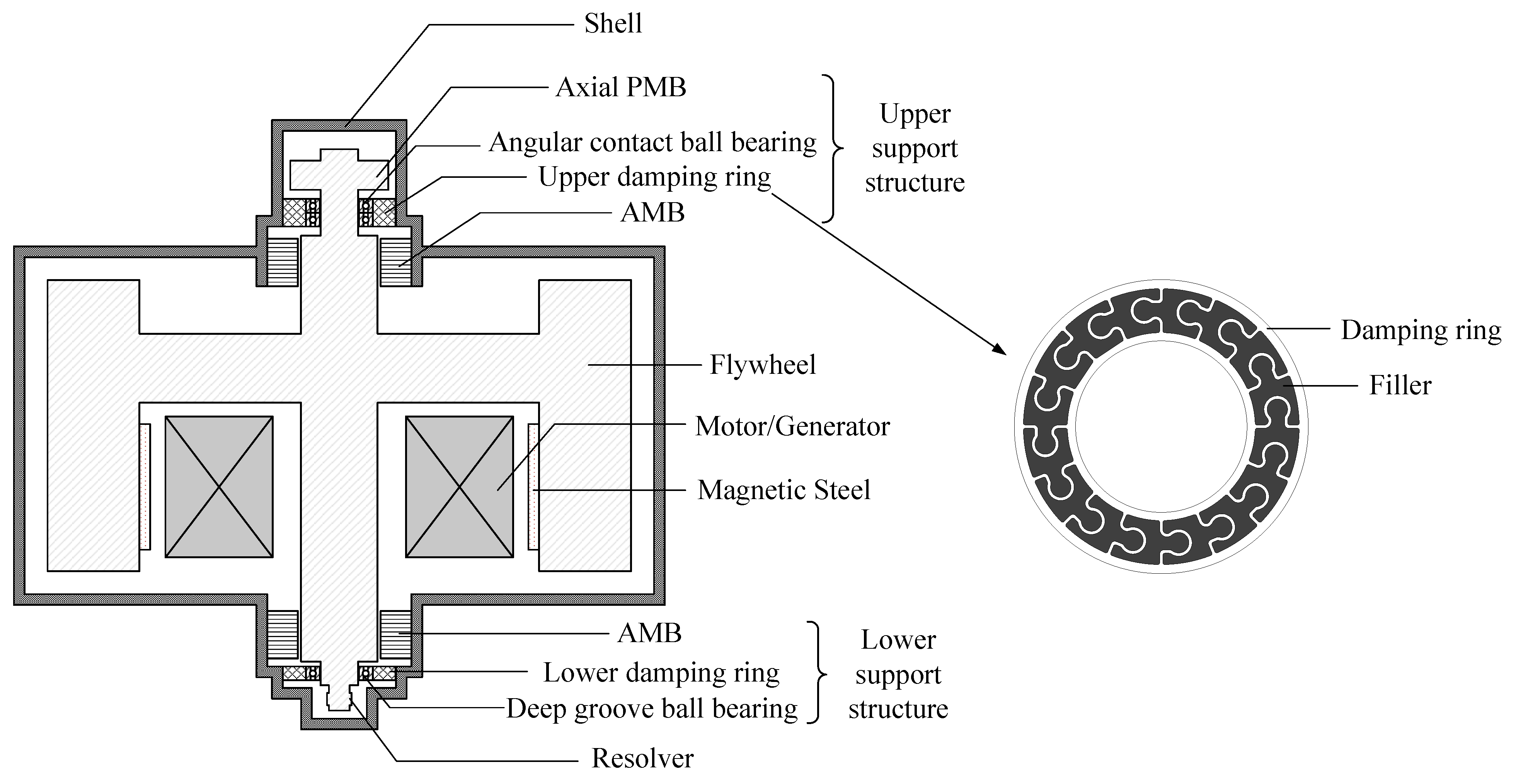
The FESS with active and passive supports consists of an active part and a passive part. Among them, the active part is the AMB, and the passive part is the mechanical bearing with a DR structure. Figure 1 shows the structural schematic diagram of the FESS with active and passive supports. Its core components are as follows:
(1)
Flywheel rotor
The flywheel rotor is composed of components such as the main shaft, hub, motor back iron, magnet steel, carbon fiber outer ring, motor rotor, and magnetic bearing rotor. Each carbon fiber outer ring is assembled with an interference fit.
(2)
Upper support structure
The upper support structure, from top to bottom, consists of the axial AMB and the upper damper in sequence. Among them, the axial AMB adopts a permanent magnet offset hybrid magnetic bearing. The upper damper is composed of mechanical bearings, DR, and AMB, which are used to reduce the amplitude of the rotor when it passes through the critical speed and enhance the stability of the system. The mechanical bearing described is a pair of angular contact ball bearings.
(3)
Lower supporting structure
The lower support structure is composed of DR, deep groove ball bearings, and AMB.
(4)
Other components
The permanent magnet synchronous motor integrated in the FESS adopts an external rotor structure. The rotor of the permanent magnet motor is installed on the inner wall of the flywheel rotor, featuring high efficiency and high power density. The rotor-bearing system of the FESS is placed in a vacuum chamber, and the motor is equipped with cooling water channels to reduce the power loss and heat generation of the system.
(5)
Design principle of DR
The DR elastic support device is composed of a ring-shaped elastic body structure and fillers. Between the inner and outer rings of the annular elastomer structure, there are multiple Ω -shaped spokes uniformly distributed along the circumference. The specific structural dimensions of the DR adopted in this paper are as follows: outer diameter 72 mm, inner diameter 42 mm, and thickness 6 mm. There is an infill structure inside the DR, with neoprene rubber as the infill material. The damping value can be adjusted by filling the spoke gap between the inner and outer rings with materials such as rubber. Among them, the elastomer structure mainly provides support stiffness, while the rubber filler only contributes a small part of the total stiffness, and the two have a parallel stiffness relationship. This design enables the DR to have both excellent elastic stiffness and significant damping characteristics. Specifically, the stiffness adjustment of the DR is mainly achieved by changing its own material and structural dimensions. For instance, by choosing different materials such as aluminum alloy and stainless steel, the stiffness can vary several times. In addition, by adjusting the spoke size between the inner and outer rings of the DR, a small range of stiffness fine-tuning can be achieved. It is worth noting that the impact of adjusting stiffness on the damping characteristics is relatively small. This is because the main damping of the DR comes from the filling material. The damping adjustment of the DR is mainly achieved by filling different materials, such as chloroprene rubber, metal rubber, plastic, wood, etc. The damping characteristics of different materials vary significantly. Meanwhile, the stiffness of these filling materials differs by tens of times from that of the DR body. Therefore, when the filling materials are replaced, the stiffness of the DR will not be significantly affected.
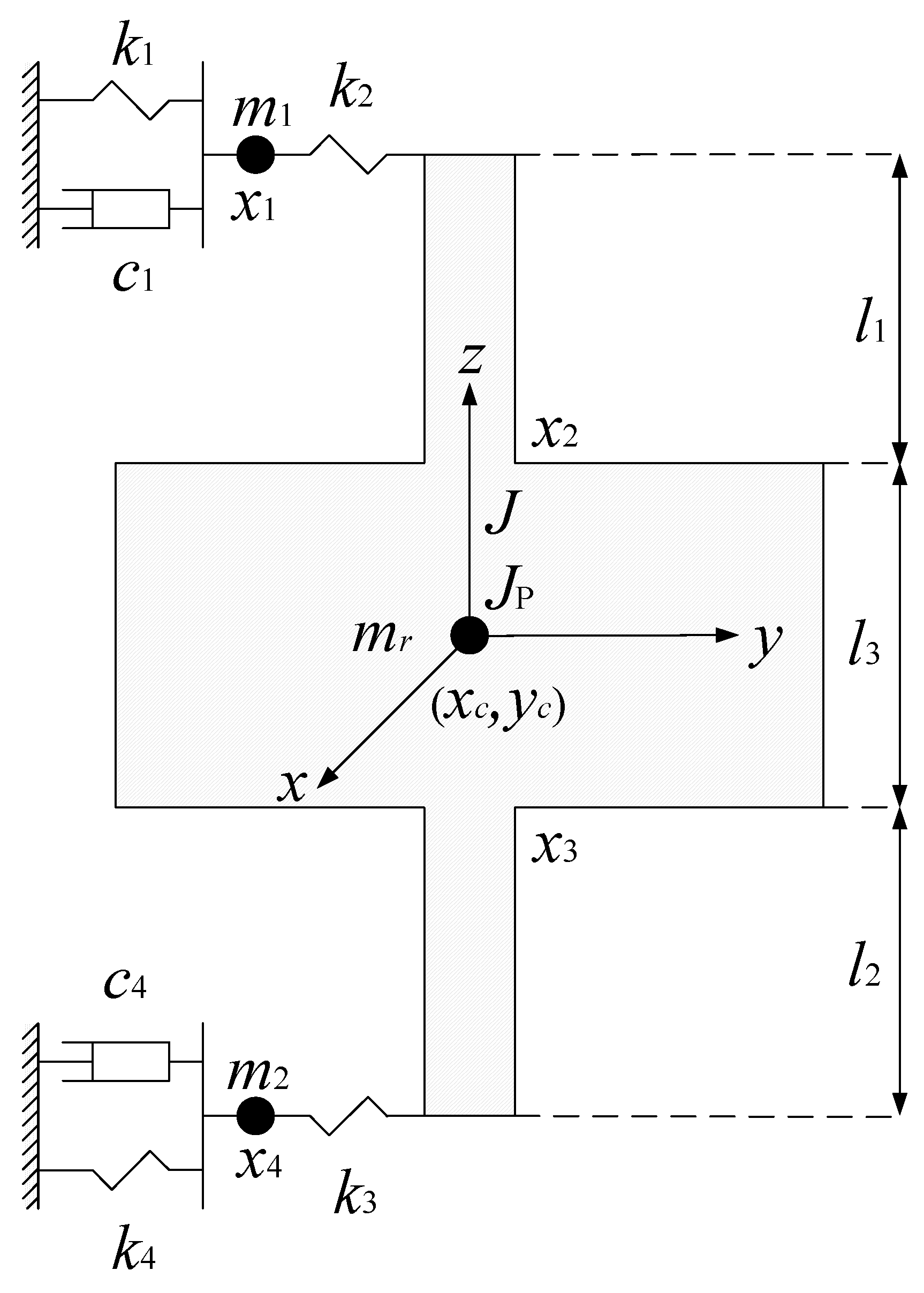
According to rotor dynamics theory, the function of the DR is to evaluate the modal damping ratio of the FESS containing the DR. Therefore, this section analyzes the free vibration characteristics of the FESS. The dynamic model of the active and passive supported FESS is shown in Figure 2. To simplify the modeling process, the following assumptions are made:
(1)
When the flywheel rotor is at rest, it is completely centered in the vertical direction, without considering the influence of gravity on the rotating shaft.
(2)
Ignore the effect of the motor’s magnetic field on the flywheel rotor.
(3)
Only radial vibration is considered, and the vibration form is linear vibration.
(4)
Simplify the DR to a linear mass-spring-damping system.
Based on the above assumptions, according to the second type of Lagrange’s equation containing dissipative force, the expressions of kinetic energy T, potential energy U, and dissipative energy Z of the active and passive supported FESS are calculated as follows:
T = 1 2 m r ( x ˙ c 2 + y ˙ c 2 ) + 1 2 J p Ω ( Ω + 2 α ˙ β ) + 1 2 J ( α ˙ 2 + β ˙ 2 ) + 1 2 m 1 ( x ˙ 1 2 + y ˙ 1 2 ) + 1 2 m 2 ( x ˙ 4 2 + y ˙ 4 2 )
U = 1 2 k 1 ( x 1 2 + y 1 2 ) + 1 2 k 4 ( x 4 2 + y 4 2 ) + 1 2 k 2 ( x 5 2 + y 5 2 ) + 1 2 k 3 ( x 6 2 + y 6 2 )
Z = 1 2 c 1 ( x ˙ 1 2 + y ˙ 1 2 ) + 1 2 c 4 ( x ˙ 4 2 + y ˙ 4 2 )
where x c = x 2 + x 3 2 , y c = y 2 + y 3 2 , α = x 2 x 3 l 3 , β = y 2 y 3 l 3 , x 5 = x 2 x 1 + l 1 ( x 2 x 3 ) l 3 , x 6 = x 3 x 4 l 2 ( x 2 x 3 ) l 3 , y 5 = y 2 y 1 + l 1 ( y 2 y 3 ) l 3 , y 6 = y 3 y 4 l 2 ( y 2 y 3 ) l 3 .
The second type of Lagrange equation containing dissipating forces is shown as follows:
d d t T q ˙ T q + U q + Z q ˙ = 0
Substitute Equations (1)–(3) into Equation (4), and finally obtain the equation in matrix form as:
M x ¨ + C x ˙ + Ω H y ˙ + K x = 0 M y ¨ + C y ˙ Ω H x ˙ + K y = 0
where M = m 1 0 0 0 0 m 3 m 4 0 0 m 4 m 3 0 0 0 0 m 2 , C = c 1 0 0 0 0 0 0 0 0 0 0 0 0 0 0 c 4 , H = 0 0 0 0 0 J p l 3 2 J p l 3 2 0 0 J p l 3 2 J p l 3 2 0 0 0 0 0 , m 3 = m r 4 + J l 3 2 , m 4 = m r 4 J l 3 2 ,
K = k 1 + k 2 k 2 ( 1 + l 1 / l 3 ) k 2 l 1 / l 3 0 k 2 ( 1 + l 1 / l 3 ) k 2 ( l 1 2 / l 3 2 + 2 l 1 / l 3 + 1 ) + k 3 l 2 2 / l 3 2 k 2 ( l 1 2 / l 3 2 + l 1 / l 3 ) k 3 ( l 2 2 / l 3 2 + l 2 / l 3 ) k 3 l 2 / l 3 k 2 l 1 / l 3 k 2 ( l 1 2 / l 3 2 + l 1 / l 3 ) k 3 ( l 2 2 / l 3 2 + l 2 / l 3 ) k 2 l 1 2 / l 3 2 + k 3 ( 1 + l 2 2 / l 3 2 + 2 l 2 / l 3 ) k 3 ( 1 + l 2 / l 3 ) 0 k 3 l 2 / l 3 k 3 ( 1 + l 2 / l 3 ) k 3 + k 4 .
Further, Equation (5) can be written as follows:
M new r ¨ + C new r ˙ + Ω H new r ˙ + K new r = 0
where r = [ x y ] T , M n e w = M 0 0 M , C n e w = C 0 0 C , K n e w = K 0 0 K , H n e w = 0 H H 0 .
Finally, the dynamic equations containing electromagnetic force and unbalanced force are given:
M new r ¨ + C new r ˙ + Ω H new r ˙ + K new r = f + f u
where f is the electromagnetic force, f = f x f y T , f x = 0 k x x 2 + k i i x 2 k x x 3 + k i i x 3 0 T , f y = 0 k x y 2 + k i i y 2 k x y 3 + k i i y 3 0 T , k x is the displacement stiffness coefficient, and k i is the current stiffness coefficient. f u is the unbalanced force, f u = u Ω 2 e j Ω t . u is the unbalance quantity, with the unit being kg·m.

2.2. Decoupling Design Based on Inverse System Theory

Since the unbalanced force of the rotor is an external disturbance force acting on the flywheel rotor, it does not change the internal coupling characteristics of the system. The suppression of external disturbances will be specifically addressed in the controller design stage. Therefore, when explaining the decoupling principle of the active and passive support flywheel rotor system, the influence of the unbalanced force is temporarily not considered. At this point, Equation (7) can be simplified as:
M new r ¨ + C new r ˙ + Ω H new r ˙ + K new r = f
Select the output variable Y = x 2 x 3 y 2 y 3 T , input variable U = u 1 u 2 u 3 u 4 T = i x 2 i x 3 i y 2 i y 3 T , and state variable X = x 1 x 2 x 3 x 4 y 1 y 2 y 3 y 4 x ˙ 1 x ˙ 2 x ˙ 3 x ˙ 4 y ˙ 1 y ˙ 2 y ˙ 3 y ˙ 4 T . At this time, the state space expression of the radial four-degree of freedom active and passive support FESS is:
X ˙ = A X + B U Y = C o X
where A = 0 I M new 1 ( K new k x ) M new 1 ( C new + Ω H new ) , B = 0 M new 1 k i , C o = C o 1 0 4 × 8 , C o 1 = 0 1 0 0 0 0 0 0 0 0 1 0 0 0 0 0 0 0 0 0 0 1 0 0 0 0 0 0 0 0 1 0 . After further derivation, the expression of the second-order derivative of the output matrix Y ¨ is obtained.
Y ¨ = C o 1 M new 1 f C new + Ω H new r ˙ K new r
Substituting the system matrix into Equation (10) yields
Y ¨ = a 1 + a 2 a 3 + a 4 a 5 + a 6 a 7 + a 8
where
a 1 = m 4 i x 3 k i k 2 l 1 x 1 l 3 k 2 l 1 2 l 3 2 + l 1 l 3 k 3 l 2 2 l 3 2 + l 2 l 3 x 2 + k x x 3 k 3 1 + l 2 2 l 3 2 + 2 l 2 l 3 + k 2 l 1 2 l 3 2 x 3 + k 3 1 + l 2 l 3 x 4 + J p y 6 Ω l 3 2 J p y 7 Ω l 3 2 m 3 2 m 4 2 ,
a 2 = m 3 i x 2 k i + k 2 1 + l 1 l 3 x 1 + k x x 2 k 2 1 + l 1 2 l 3 2 + 2 l 1 l 3 + k 3 l 2 2 l 3 2 x 2 k 2 l 1 2 l 3 2 + l 1 l 3 k 3 l 2 2 l 3 2 + l 2 l 3 x 3 k 3 l 2 x 4 l 3 J p y 6 Ω l 3 2 + J p y 7 Ω l 3 2 m 3 2 m 4 2 ,
a 3 = m 3 i x 3 k i k 2 l 1 x 1 l 3 k 2 l 1 2 l 3 2 + l 1 l 3 k 3 l 2 2 l 3 2 + l 2 l 3 x 2 + k x x 3 k 3 1 + l 2 2 l 3 2 + 2 l 2 l 3 + k 2 l 1 2 l 3 2 x 3 + k 3 1 + l 2 l 3 x 4 + J p y 6 Ω l 3 2 J p y 7 Ω l 3 2 m 3 2 m 4 2 ,
a 4 = m 4 i x 2 k i + k 2 1 + l 1 l 3 x 1 + k x x 2 k 2 1 + l 1 2 l 3 2 + 2 l 1 l 3 + k 3 l 2 2 l 3 2 x 2 k 2 l 1 2 l 3 2 + l 1 l 3 k 3 l 2 2 l 3 2 + l 2 l 3 x 3 k 3 l 2 x 4 l 3 J p y 6 Ω l 3 2 + J p y 7 Ω l 3 2 m 3 2 m 4 2 ,
a 5 = m 3 i y 2 k i + k 2 1 + l 1 l 3 y 1 + k x y 2 k 2 1 + l 1 2 l 3 2 + 2 l 1 l 3 + k 3 l 2 2 l 3 2 y 2 k 2 l 1 2 l 3 2 + l 1 l 3 k 3 l 2 2 l 3 2 + l 2 l 3 y 3 k 3 l 2 y 4 l 3 + J p x 6 Ω l 3 2 J p x 7 Ω l 3 2 m 3 2 m 4 2 ,
a 6 = m 4 i y 3 k i k 2 l 1 y 1 l 3 k 2 l 1 2 l 3 2 + l 1 l 3 k 3 l 2 2 l 3 2 + l 2 l 3 y 2 + k x y 3 k 3 1 + l 2 2 l 3 2 + 2 l 2 l 3 + k 2 l 1 2 l 3 2 y 3 + k 3 1 + l 2 l 3 y 4 J p x 6 Ω l 3 2 + J p x 7 Ω l 3 2 m 3 2 m 4 2 ,
a 7 = m 4 i y 2 k i + k 2 1 + l 1 l 3 y 1 + k x y 2 k 2 1 + l 1 2 l 3 2 + 2 l 1 l 3 + k 3 l 2 2 l 3 2 y 2 k 2 l 1 2 l 3 2 + l 1 l 3 k 3 l 2 2 l 3 2 + l 2 l 3 y 3 k 3 l 2 y 4 l 3 + J p x 6 Ω l 3 2 J p x 7 Ω l 3 2 m 3 2 m 4 2 ,
a 8 = m 3 i y 3 k i k 2 l 1 y 1 l 3 k 2 l 1 2 l 3 2 + l 1 l 3 k 3 l 2 2 l 3 2 + l 2 l 3 y 2 + k x y 3 k 3 1 + l 2 2 l 3 2 + 2 l 2 l 3 + k 2 l 1 2 l 3 2 y 3 + k 3 1 + l 2 l 3 y 4 J p x 6 Ω l 3 2 + J p x 7 Ω l 3 2 m 3 2 m 4 2 .
In the equation, since the electromagnetic force f is a function of u 1 , u 2 , u 3 , and u 4 , the Y ¨ explicitly contains the input variable U. By using the above equation, the functional relationship between each input variable ( u 1 , u 2 , u 3 , u 4 ) and Y ¨ can be inversely solved; that is, U = f ( Y ¨ ) .
Before solving the equation, the reversibility of Equation (11) must first be analyzed. The corresponding Jacobian matrix is given by:
D = 2 Y ¨ ( U ) U = 2 y ¨ 1 u 1 2 2 y ¨ 1 u 2 2 2 y ¨ 1 u 3 2 2 y ¨ 1 u 4 2 2 y ¨ 2 u 1 2 2 y ¨ 2 u 2 2 2 y ¨ 2 u 3 2 2 y ¨ 2 u 4 2 2 y ¨ 3 u 1 2 2 y ¨ 3 u 2 2 2 y ¨ 3 u 3 2 2 y ¨ 3 u 4 2 2 y ¨ 4 u 1 2 2 y ¨ 4 u 2 2 2 y ¨ 4 u 3 2 2 y ¨ 4 u 4 2
Substitute the data and solve as follows:
D = k i m 3 m 3 2 m 4 2 k i m 4 m 3 2 m 4 2 0 0 k i m 4 m 3 2 m 4 2 k i m 3 m 3 2 m 4 2 0 0 0 0 k i m 3 m 3 2 m 4 2 k i m 4 m 3 2 m 4 2 0 0 k i m 4 m 3 2 m 4 2 k i m 3 m 3 2 m 4 2
Take the determinant of the Jacobian matrix D and set it to zero. It can be solved that k i approaches 0. Since k i is the current stiffness coefficient and is never zero, the determinant of the Jacobian matrix D is not zero; that is, Equation (11) is invertible. By inverting Equation (11), the functional relationship between each input variable ( u 1 , u 2 , u 3 , u 4 ) and Y ¨ can be obtained, as shown below:
i x 2 = 1 k i l 3 2 k 3 l 2 2 x 2 + l 3 2 ( m 3 x ¨ 2 + m 4 y ¨ 3 k 2 x 1 + k 2 x 2 k x x 2 ) + k 2 l 1 2 ( x 2 x 3 ) k 3 l 2 2 x 3 l 3 k 2 l 1 ( x 1 2 x 2 + x 3 ) + k 3 l 2 ( x 3 x 4 ) + J p y 6 Ω J p y 7 Ω ,
i x 3 = 1 k i l 3 2 k 2 l 1 l 3 ( x 1 x 2 ) k 3 l 2 2 x 2 + k 3 l 2 2 x 3 + k 2 l 1 2 ( x 2 + x 3 ) k 3 l 2 l 3 ( x 2 2 x 3 + x 4 ) + l 3 2 ( m 4 x ¨ 2 + m 3 x ¨ 3 + k 3 x 3 k x x 3 k 3 x 4 ) J p y 6 Ω + J p y 7 Ω ,
i y 2 = 1 k i l 3 2 k 3 l 2 2 y 2 + l 3 2 ( m 3 y ¨ 2 + m 4 y ¨ 3 k 2 y 1 + k 2 y 2 k x y 2 ) + k 2 l 1 2 ( y 2 y 3 ) k 3 l 2 2 y 3 l 3 k 2 l 1 ( y 1 2 y 2 + y 3 ) + k 3 l 2 ( y 3 y 4 ) J p x 6 Ω + J p x 7 Ω ,
i y 3 = 1 k i l 3 2 k 2 l 1 l 3 ( y 1 y 2 ) k 3 l 2 2 y 2 + k 3 l 2 2 y 3 + k 2 l 1 2 ( y 2 + y 3 ) k 3 l 2 l 3 ( y 2 2 y 3 + y 4 ) + l 3 2 ( m 4 y ¨ 2 + m 3 y ¨ 3 + k 3 y 3 k x y 3 k 3 y 4 ) + J p x 6 Ω J p x 7 Ω .
After decoupling by the inverse system method, the transfer functions from the new input variables ( v 1 , v 2 , v 3 , v 4 ), ( v 1 = x ¨ 2 , v 2 = x ¨ 3 , v 3 = y ¨ 2 , v 4 = y ¨ 3 ) to the output variable Y are all 1 s 2 . Therefore, after decoupling by the inverse system method, the originally strongly coupled radial four-degree of freedom active and passive support FESS has been transformed into four mutually decoupled single-input, single-output systems, and each subsystem is a pseudo-linear system with a transfer function of 1 s 2 .

3. Full-Speed Range Control System Design

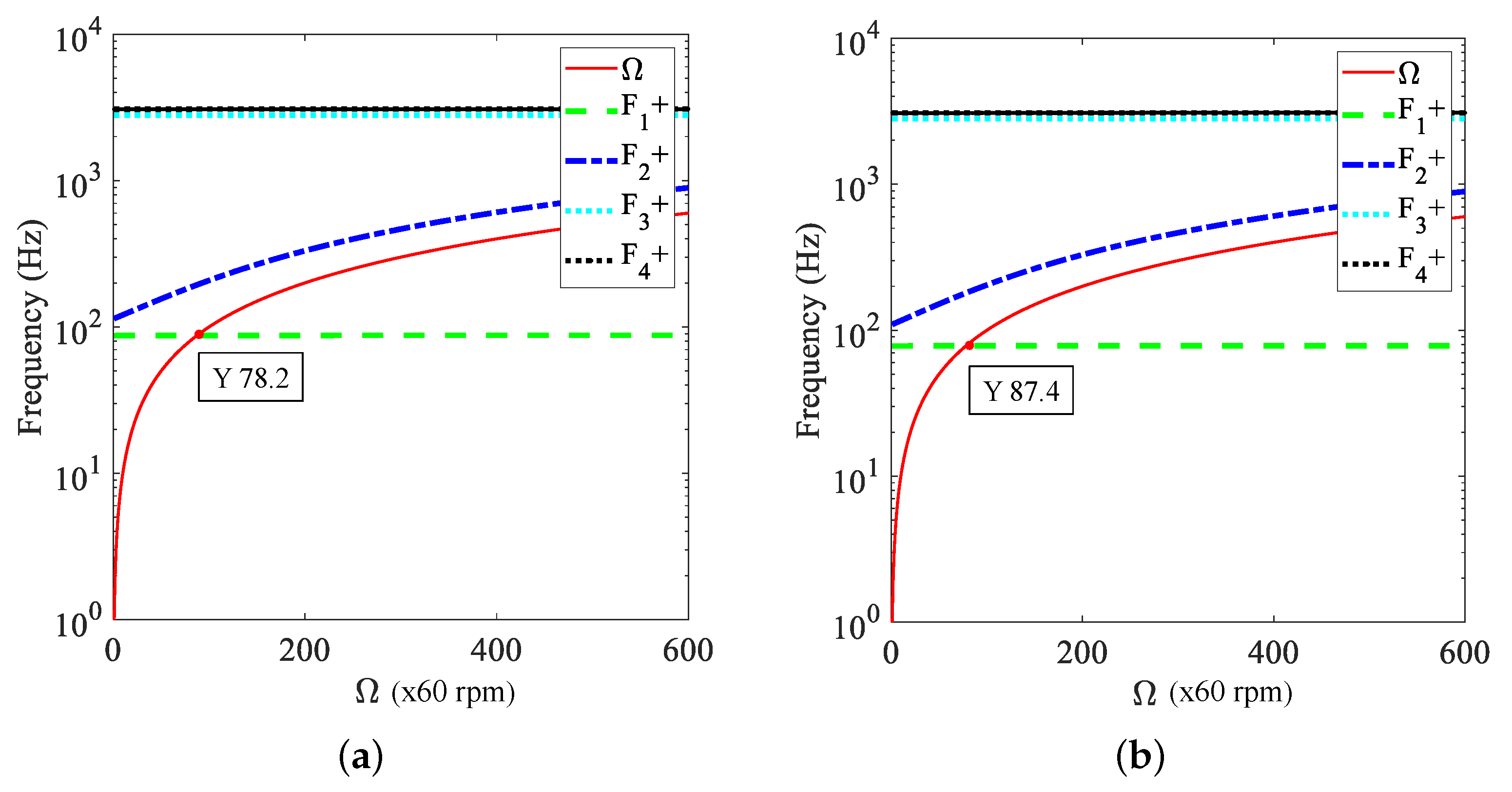
Based on the dynamic model of the FESS with the DR active and passive support established in Section 2 and the 4-DOF inverse system decoupling theory, this section first analyzes the dynamic characteristics and core disturbance mechanisms of the system within the full-speed range. Then, in view of the characteristic differences in the “subcritical-critical-supercritical” three stages, a segmented collaborative vibration suppression strategy is designed. The expression of the control law, parameter design method, and speed switching logic for each stage is clarified. Ultimately, stable and high-precision control within the full-speed range is achieved. Under the main passive and auxiliary active support architecture of mechanical bearings and magnetic bearings, the dynamic behavior of the system shows significant speed dependence: in the subcritical stage ( Ω < 0.9 Ω c ), the vibration is mainly caused by the unbalanced excitation at the synchronous frequency (where Ω c is the critical speed of the system); in the critical stage ( 0.9 Ω c Ω 1.1 Ω c ), resonance amplification effects induced by unbalanced excitation are prone to occur; in the supercritical stage ( Ω > 1.1 Ω c ), the gyroscopic effect dominates, and precession/nutation instability is likely to occur. It should be noted that the critical interval of 0.9 Ω c to 1.1 Ω c is based on the conventional definition of the resonance peak region in rotor dynamics, and the resonance effect on system vibration is most significant within this interval. Through the simulation calculation of the critical speed, as shown in Figure 3 (The first-order forward whirling is represented by F 1 + ; the same applies to others.), the critical speed of the system studied in this paper is 78.2 Hz (i.e., 4692 rpm), which is slightly lower than that of the mechanical bearing system with a DR at 87.4 Hz. This is due to the displacement stiffness of the magnetic bearing weakening the overall support stiffness of the system. Based on the above analysis, the control strategy design is carried out in stages in the following text.

3.1. Design of Control Law for Subcritical Speed Range ( Ω < 0.9 Ω c )

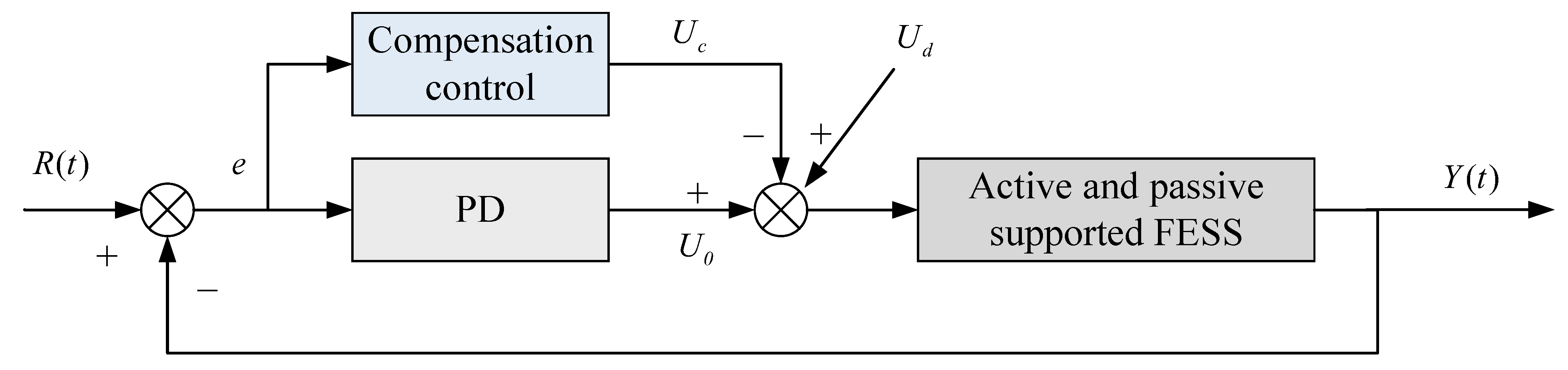
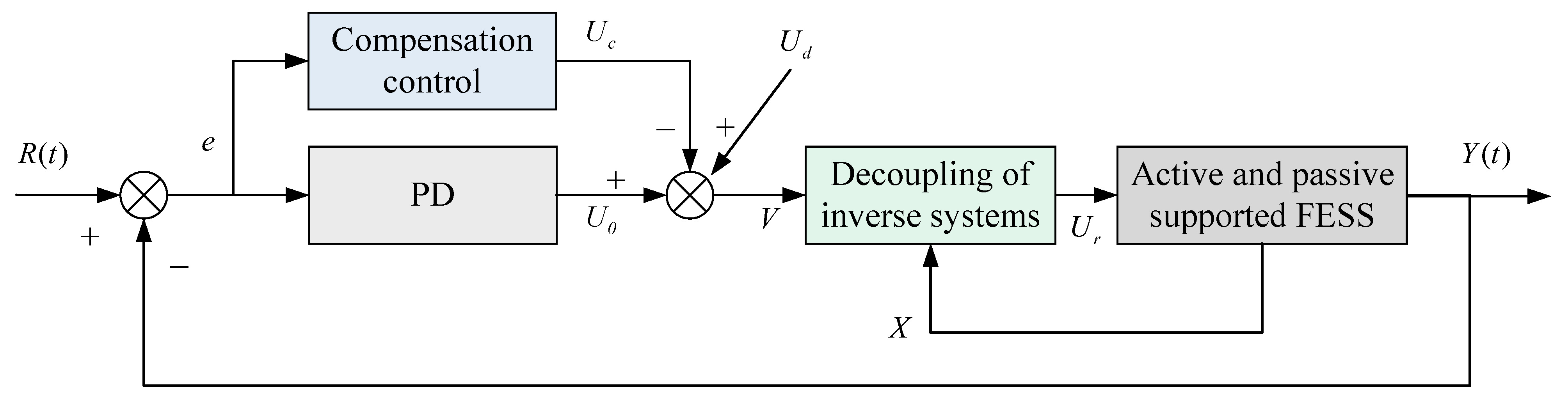
In the subcritical speed stage, after the system is decoupled by the inverse system, 4-DOF independent control is achieved. The core disturbance is the unbalanced excitation at the synchronous frequency as the rotational speed increases, and the influence of external load disturbances is relatively small. Therefore, the control objective in this stage is to precisely suppress the low-frequency vibration caused by the unbalanced excitation while ensuring the stability of the system, laying the foundation for the subsequent critical speed crossing. A collaborative control strategy integrating inverse system decoupling, PD feedback control, and unbalance compensation is adopted. Inverse system decoupling is the basis to achieve independent control of each channel. PD feedback control is necessary to ensure the basic stability of the system. And unbalance compensation is needed to precisely counteract the low-frequency components of the unbalanced excitation. The core advantage of this strategy lies in the ability to pre-suppress the predictable unbalanced disturbance through unbalance compensation, avoiding the lag problem inherent in pure PD feedback control. The principle block diagrams of PD control combined with unbalance compensation are shown in Figure 4 and Figure 5, where R ( t ) is the reference displacement input, Y ( t ) is the system displacement output, and the controlled object is the active and passive supported FESS after inverse system decoupling. After inverse system decoupling, the single-channel transfer function is simplified to 1 s 2 . U d is the equivalent disturbance voltage, which is the external load disturbance obtained from the unbalanced excitation according to the equivalent principle, and its expression is shown in Equation (14).
V is the input of the inverse system. After being processed by the decoupling control law of the inverse system, the control variable U r is obtained. It is converted into current by the power amplifier (included in the active and passive support FESS) and input into the flywheel rotor system. According to the equivalent principle, the unbalance disturbance is equivalent to the disturbance voltage U d . The expression of the equivalent disturbance voltage is as follows:
U d = α d sin ( ω t ) + β d cos ( ω t )
where α d and β d are the corresponding Fourier coefficients. The control variable U 0 obtained through the PD controller is as follows:
U 0 = e ( k p + k d s )
where k p and k d are the proportional and differential coefficients of the PD controller respectively. e represents the feedback error. The expression of the unbalance compensation voltage U c is as follows:
U c = α c sin ( ω t ) + β c cos ( ω t )
where α c and β c are the corresponding Fourier coefficients. Obviously, when α c = α d and β c = β d , the system imbalance is completely compensated. The expression of the input V of the inverse system decoupling control law is as follows:
V = U 0 U c + U d

3.2. Design of Control Law for Critical Speed Range ( 0.9 Ω c Ω 1.1 Ω c )

During the critical speed stage, the system is in a resonance-sensitive zone, where vibrations caused by unbalanced excitation are significantly amplified, easily leading to rotor–stator rub and threatening system safety. Therefore, the core control objective in this stage is to dynamically adjust the system’s equivalent stiffness to shift the natural frequency away from the excitation frequency corresponding to the current speed, thereby avoiding resonance. At the same time, it is necessary to coordinate the DR and the active damping of the magnetic bearing to ensure the stability of the speed crossing process. This section adopts a strategy integrating continuous variable stiffness control and damping coordinated regulation. By actively adjusting the control stiffness through magnetic bearings, the dynamic increase of the system’s equivalent stiffness is achieved, thereby enhancing the system’s natural frequency and avoiding the natural frequency matching the excitation frequency corresponding to the current rotational speed. The DR provides the basic energy dissipation capacity, and the magnetic bearing enhances the vibration reduction effect by adjusting the damping coefficient. The two work together to suppress resonance vibration. To avoid sudden changes in vibration during the speed switching process, a gradual stiffness transition strategy is adopted: before entering the critical zone, the magnetic bearing control mode is gradually transitioned from the “subcritical unbalance compensation mode” to the “variable stiffness control mode”; during the critical zone crossing process, the damping coefficient and stiffness value are kept in coordinated change; after leaving the critical zone, the control mode is gradually transitioned to the “supercritical gyroscopic effect suppression mode”. In this section, PD control is adopted to adjust the stiffness and damping of the magnetic bearing. First, the expressions of the equivalent stiffness and equivalent damping of the system under PD control need to be derived. For a single degree of freedom linear mass-spring-damper system, its motion equation is:
m x ¨ + d x ˙ + k x = F
where m represents mass, d represents damping coefficient, and k represents stiffness. Taking the Laplace transform of Equation (18), the frequency characteristic equation of the system is obtained as:
x ( j ω ) = F ( j ω ) m ω 2 + k + j ω d
Due to the limitations of the rotor processing technology, there will definitely be an unbalance in the flywheel rotor system. As mentioned above, the motion equation of the active and passive supported FESS with unbalance is given by Equation (7). For a unit negative feedback system under PID control, the transfer function relationship between the control variable U and the displacement r is:
U ( s ) = G ( s ) r ( s ) = P I 1 s D s r ( s )
G ( s ) is the transfer function of the PID control unit feedback, where P represents the proportional coefficient, I represents the integral coefficient, and D represents the differential coefficient. Substituting Equation (20) into Equation (7) and finally neglecting the integral term, the frequency equation of the system can be obtained as:
r ( j ω ) = f 1 ( j ω ) M new ω 2 + K new k x + k i P + j C new ω + Ω H new ω + k i D ω
By comparing Equation (19) and Equation (21), it is easy to obtain the expressions of the equivalent stiffness k e and equivalent damping d e of the active and passive supported FESS relative to the mass-spring-damper system.
k e = K new k x + k i P
d e = C new + Ω H new + k i D
The core of the variable stiffness regulation law design lies in determining the stiffness adjustment range and the gradual change rule. Firstly, the PD parameter adjustment interval is preliminarily determined through the root locus stability criterion. Further, the PD parameter adjustment interval is optimized based on the Bode diagram and the steady-state error of the system. Then, the stiffness adjustment range is determined according to this adjustment interval, and finally, the stiffness adjustment is carried out. The expression of the single-channel variable stiffness control law is as follows:
k mb ( Ω ) = k mbo + k rise Ω 0.9 Ω c 0.2 Ω c ( 0.9 Ω c < Ω < 1.1 Ω c )
k eff ( Ω ) = k m + k mb ( Ω )
where k mb is the real-time stiffness of the magnetic bearing, k mbo is the initial stiffness of the magnetic bearing in the subcritical state, and k rise is the total increase in stiffness during the critical rotational speed stage. The final equivalent stiffness k eff is the sum of the real-time stiffness of the magnetic bearing k mb and the stiffness of the mechanical bearing k m . As can be seen from Equation (24), the stiffness of the magnetic bearing changes linearly with the rotational speed, ensuring the smoothness of the process of crossing the critical zone.

3.3. Supercritical Speed Range Control Law Design ( Ω > 1.1 Ω c )

In the supercritical speed range, the gyroscopic effect intensifies significantly, inducing coupling between the rotor’s precession and nutation modes and thus increasing the risk of system instability. Therefore, the core control objective in this stage is to completely counteract the mode coupling caused by the gyroscopic effect, maintain the dynamic stability of the rotor, and simultaneously suppress the vibrations induced by the residual unbalanced excitation. Traditional methods for suppressing the gyroscopic effect often employ cross-feedback control (CFC), which introduces phase compensation signals related to the speed in the cross channels to counteract the gyroscopic torque. However, in the active–passive bearing system, the structural coupling between mechanical bearings and magnetic bearings leads to a decrease in the compensation accuracy of CFC, making it difficult to achieve complete mode decoupling. Based on the inverse system decoupling theory presented in Section 2, this paper directly achieves complete decoupling of the 4-DOF system to eliminate the mode coupling caused by the gyroscopic effect without the need for complex cross-feedback channel design. After inverse system decoupling, the precession and nutation modes are completely independent, and each mode can be stably controlled by an independent PD controller, significantly simplifying the control design in the supercritical stage.

3.4. Full-Speed Range Control Switching Logic

To achieve smooth and stable control across the entire speed range, a segmented switching logic based on speed thresholds is designed. The core parameters and switching process are as follows:
Switching thresholds: Taking the critical speed Ω c as the reference, the switching thresholds are set at 0.9 Ω c (subcritical to critical) and 1.1 Ω c (critical to supercritical).
Transition strategy: A transition zone of 50 rpm in width is set around the switching thresholds. Within this zone, a weighted superposition of the control laws from the previous and subsequent stages is adopted, with the weights varying linearly with speed (for example, in the subcritical to critical transition zone, the weight of the subcritical control law linearly decreases from 1 to 0, while that of the critical control law linearly increases from 0 to 1).

4. Simulation Verification

To verify the effectiveness of the scheme incorporating passive and active support with DR, inverse system based 4-DOF full decoupling, and full-speed range segmented control proposed in this paper, a series of simulation verifications is carried out in this section. Firstly, the basic simulation parameters are clarified, and then the decoupling performance of the system, the control performance in different speed stages, the global performance in the full-speed range, the advantages of the active and passive collaboration, and the robustness of the system are verified in sequence. Finally, the superiority of the scheme proposed in this paper is highlighted through multi-dimensional comparisons. Table 1 lists the core structure and dynamic parameters of the FESS, providing a basis for simulation modeling.

4.1. Decoupling Performance Verification

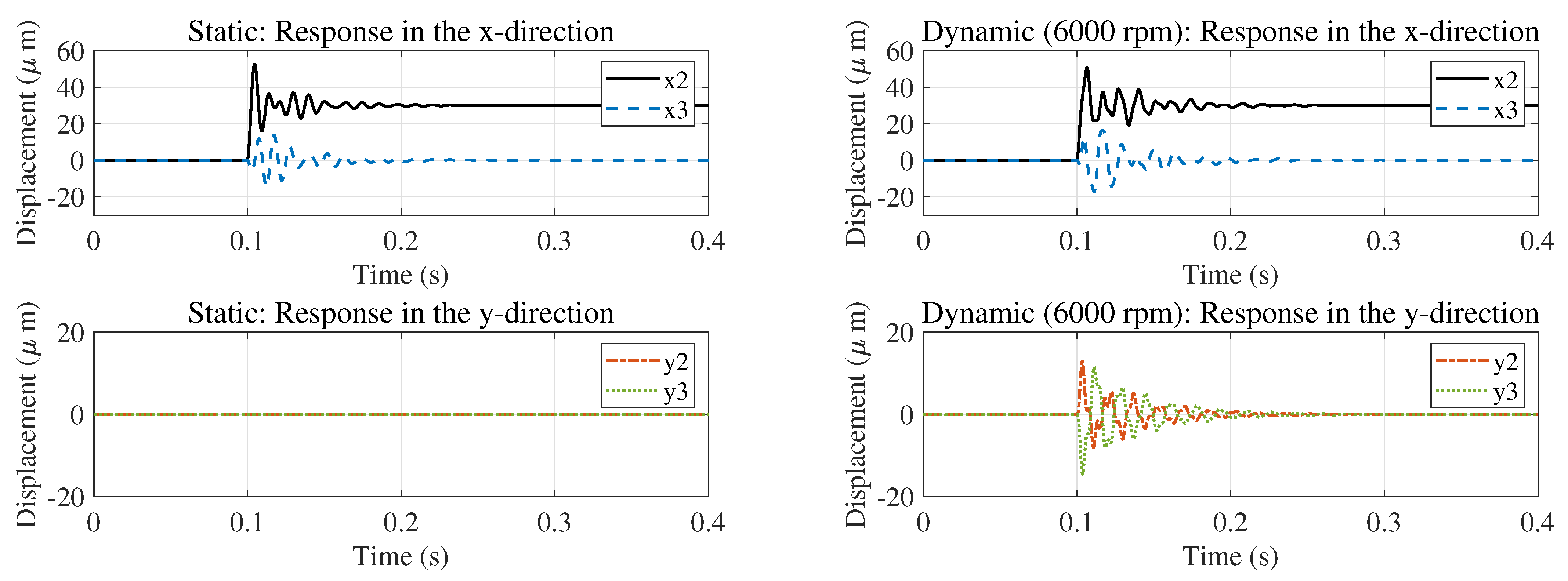
This subsection aims to verify whether the inverse system decoupling algorithm proposed in Section 2 can achieve complete decoupling of the radial 4-DOF, eliminating the structural coupling and gyroscopic effect coupling among the degrees of freedom, laying the foundation for subsequent staged control. The system’s static condition and the coupled condition at 6000 rpm are shown in Figure 6. In both conditions, only the displacement of the x 2 degree of freedom is adjusted, which suddenly changes from 0 to 30 μm at 0.5 s. As shown in Figure 6, under the static condition, the excitation of the x 2 degree of freedom only causes a response in the x 3 degree of freedom, indicating that only structural coupling exists at this time; under the dynamic condition at 6000 rpm, the excitation of the x 2 degree of freedom causes significant responses in the other three degrees of freedom, verifying that the gyroscopic effect intensifies the system coupling and highlighting the necessity of decoupling.
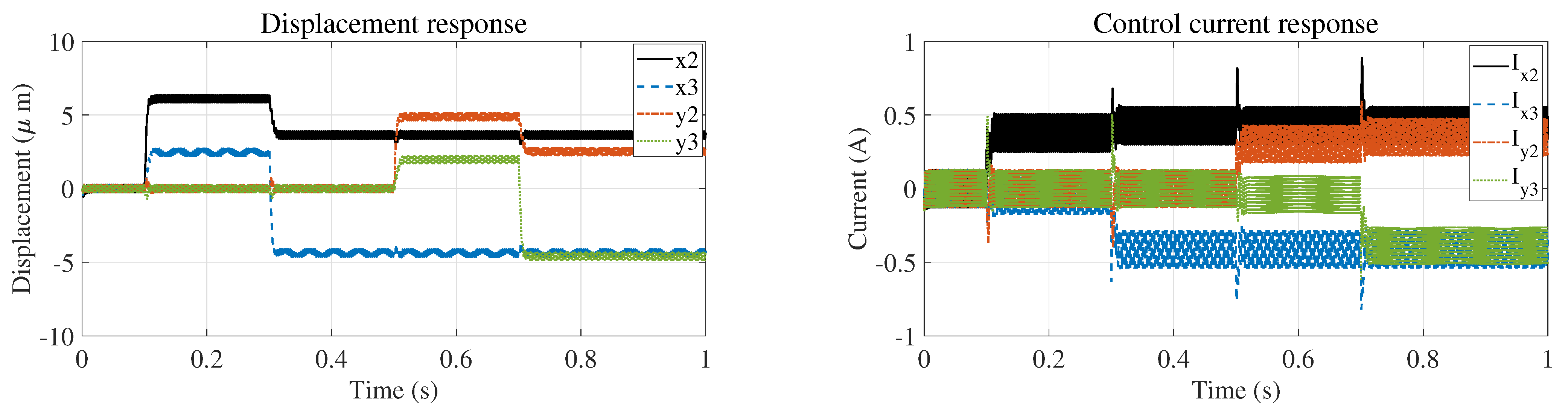
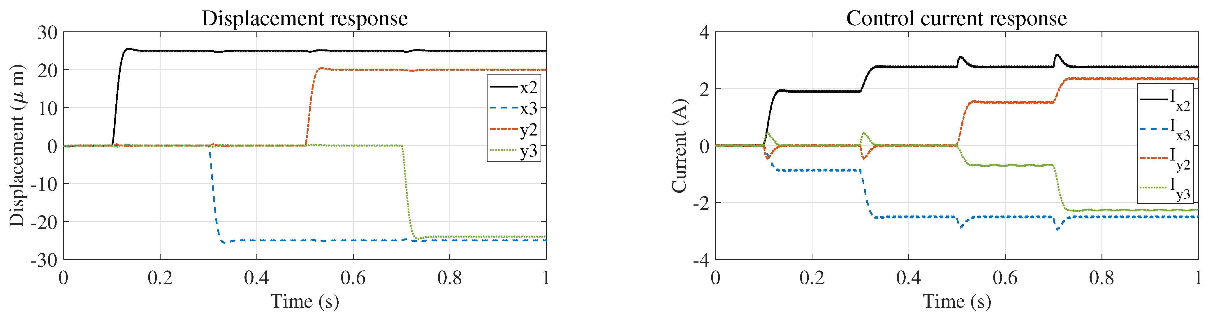
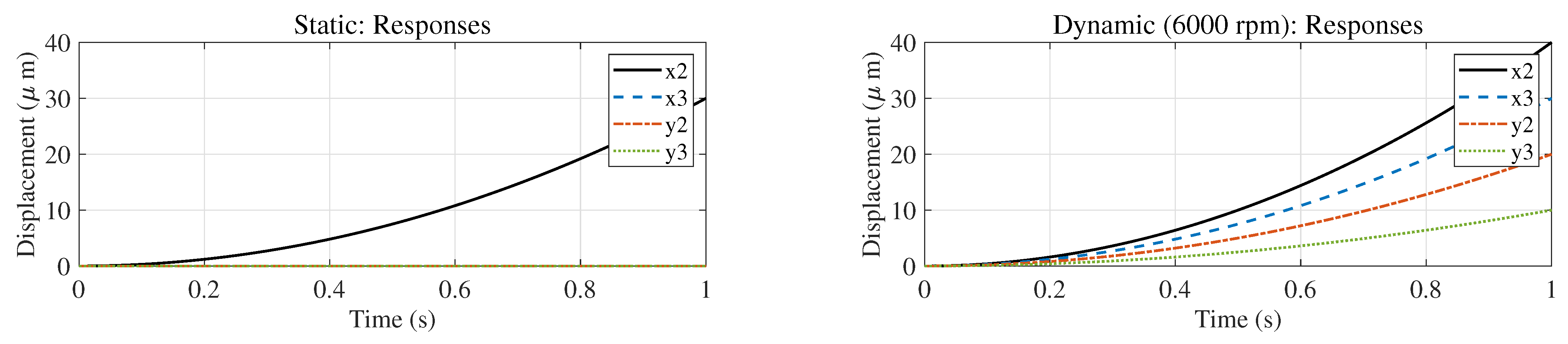
Subsequently, the performance of the decoupled system was analyzed. The static and 6000 rpm working conditions’ coupling characteristics are shown in Figure 7. Under the static condition, only a step signal of 6 × 10 5 m was input to x 2 (initial displacement and velocity were both 0, step size was 2 × 10 5 s, and duration was 1 s). The output of x 2 presented a quadratic curve (corresponding to the transfer function 1 s 2 ), while the other degrees of freedom were nearly zero, achieving decoupling. The final displacement of x 2 was 30 μm, consistent with the result of the second integral, verifying the accuracy of the program. Under the 6000 rpm condition, step signals (amplitudes were 8 × 10 5 m, 6 × 10 5 m, 4 × 10 5 m, and 2 × 10 5 m respectively) were input to the x 2 , x 3 , y 2 , and y 3 positions. The steady-state output displacements of each channel were 40 μm, 30 μm, 20 μm, and 10 μm, respectively, which were in line with the theoretical results, and there was no cross-coupling interference, achieving complete decoupling of the four degrees of freedom.

4.2. Performance Analysis of Control in the Entire Speed Range

Based on the decoupling verification results in Section 4.1, this section verifies the performance of the piecewise control strategy proposed in this paper in the three stages of “subcritical-critical-supercritical”, respectively.

4.2.1. Subcritical Speed Stage

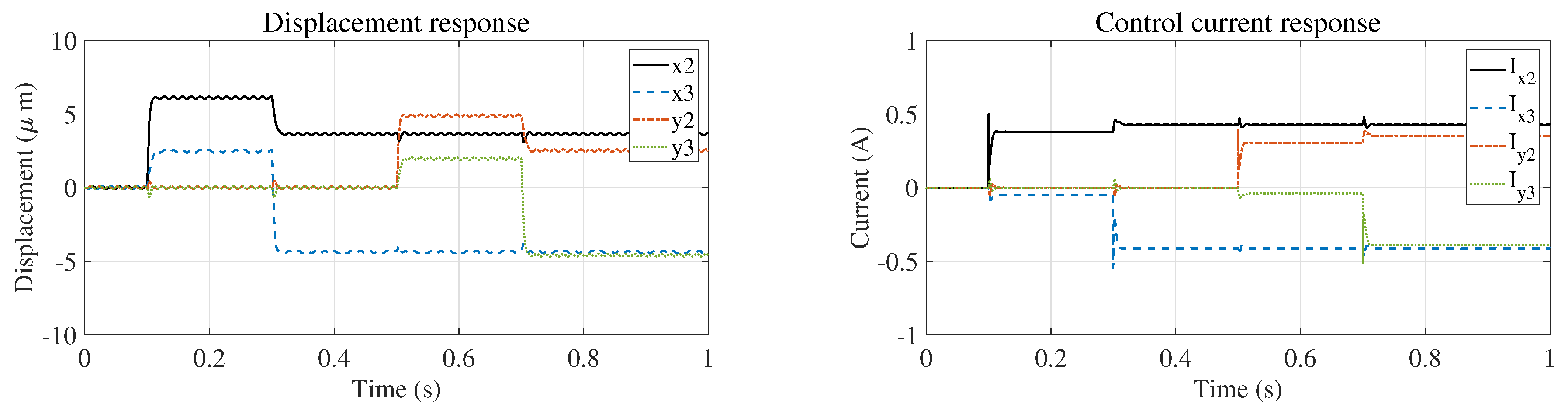
This subsection verifies the unbalanced vibration suppression effect of the strategy incorporating inverse system decoupling, PD control, and unbalance compensation in the subcritical stage, and compares the steady-state control accuracy of the coupled system. First, the setpoint tracking simulation is carried out. The proportional gain k p and derivative gain k d of the PD controller are set to 2 × 10 4 and 2 × 10 2 , respectively. Each control channel is configured such that the x 2 channel steps to 25 μm at 0.1 s, the x 3 channel steps to −25 μm at 0.3 s, the y 2 channel steps to 20 μm at 0.5 s, and the y 3 channel steps to −24 μm at 0.7 s. Setpoint tracking simulation results are presented in Figure 8 and Figure 9. The convergence-stage average error of the coupled system (defined as the mean displacement error over the final 10% of the simulation steady-state phase) reaches 21.36 μm, 20.63 μm, 17.48 μm, and 19.41 μm for the x 2 , x 3 , y 2 , and y 3 channels, respectively. The average error of the decoupled system in this paper is only about 0.027 μm, and the improvement in steady-state accuracy exceeds 99.85% for all channels. Moreover, the coupled system has obvious channel cross-interference (a sudden change in the displacement of one channel causes fluctuations in other channels), while the decoupled system has no cross-interference, verifying the synergistic enhancement effect of decoupling on unbalanced vibration suppression.
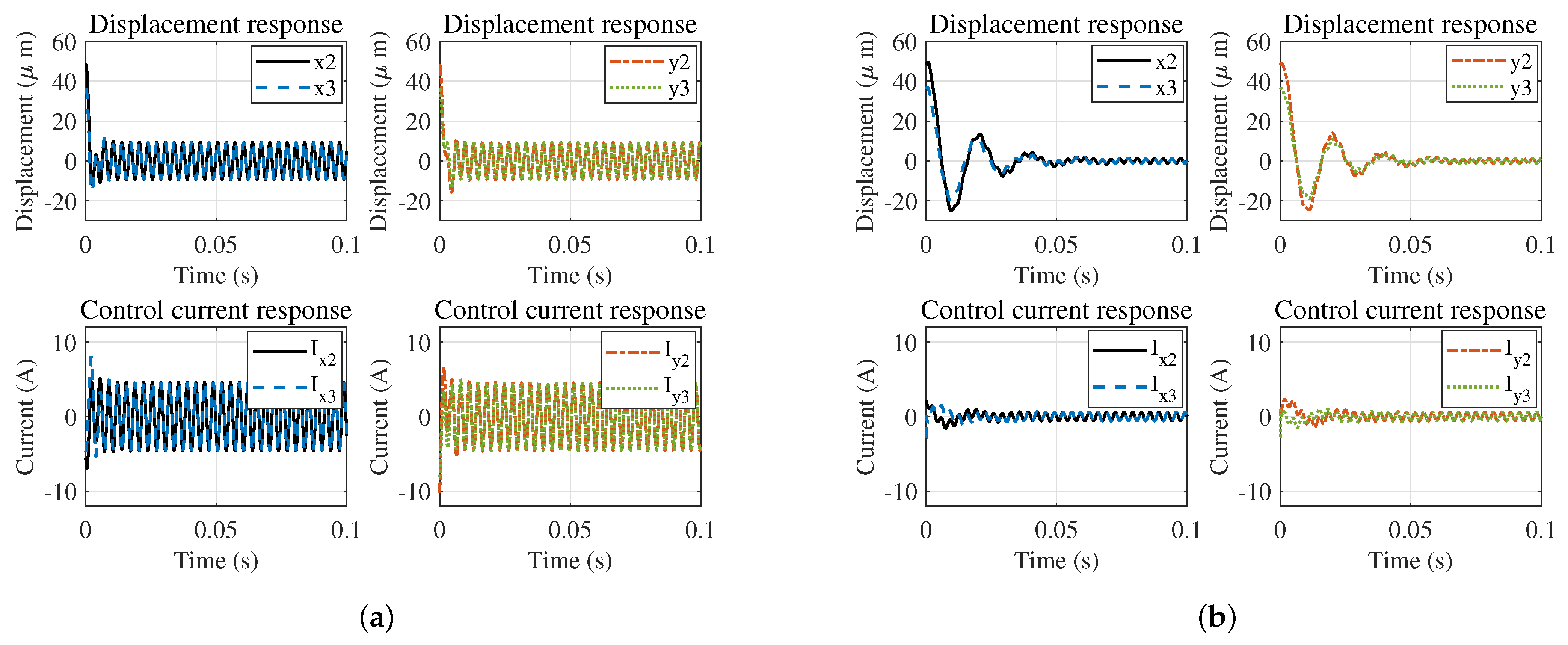
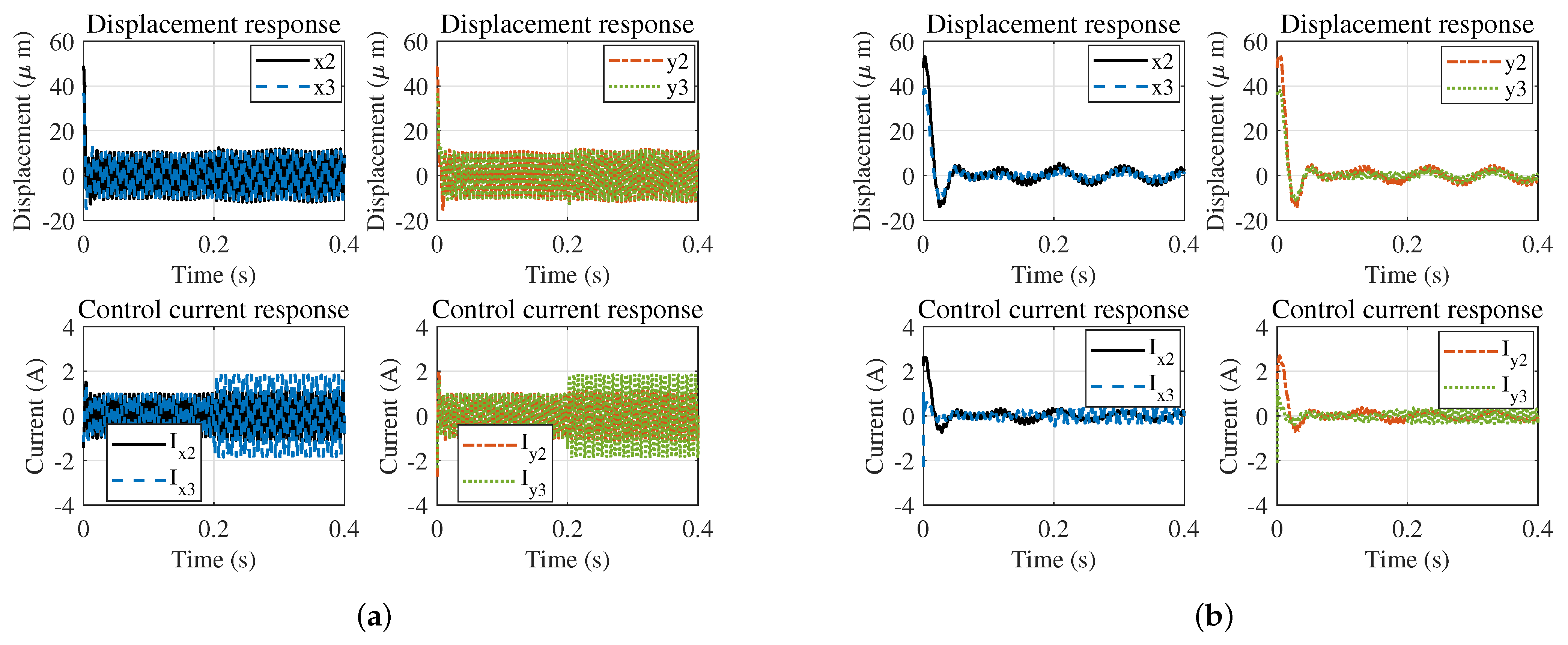
The following is the simulation of initial disturbance control. The k p and k d of the PD controller are set to 2 × 10 4 and 1 × 10 2 , respectively. The simulation results of initial disturbance suppression are shown in Figure 10. The average error of the coupled system is 5.06 μm, while that of the decoupled system in this paper is 1.54 μm, with an overall accuracy improvement of 68.30%. Among them, the improvement in the x-direction channel exceeds 76%, and that in the y-direction exceeds 57%. Therefore, in the subcritical stage, the strategy combining decoupling and unbalance compensation proposed in this paper can effectively eliminate the influence of channel coupling and unbalanced excitation. Its steady-state control accuracy is significantly higher than that of the coupled system, laying a solid foundation for critical speed traversal.

4.2.2. Critical Speed Stage

This section aims to verify the effectiveness of the continuous variable stiffness control (CVSC) strategy proposed in this paper within the critical speed range. The core objective is to actively shift the critical speed by dynamically tuning magnetic bearing control parameters to modify the system’s equivalent stiffness, thereby avoiding the resonance zone during speed ramp-up and suppressing resonance amplification. The implementation of the CVSC strategy is based on the premise of “system stability” and “steady-state accuracy meeting the standard”. Therefore, the simulation verification process is divided into three steps: determining the PD control parameter range that meets the constraints; deriving the stiffness adjustment range based on the equivalent stiffness/damping equation; and conducting variable stiffness adjustment simulations within the target parameter range to verify the critical speed shift effect. To ensure system stability during variable stiffness adjustment and steady-state displacement error less than 8 μm, a three-stage screening procedure involving root locus preliminary screening, Bode plot fine screening, and closed-loop response verification was adopted to determine the stable domain of PD parameters (see Figure 11). First, preliminary screening was performed via the root locus method. Based on the closed-loop transfer function of the active–passive supported FESS, the root locus was plotted with k d fixed and k p varied to identify the k p range that keeps all system poles in the left-half complex plane. Similarly, fixing k p enabled the derivation of the stable k d range via root locus analysis, yielding the boundary of the k p k d two-dimensional stable domain. Second, fine screening was conducted using Bode plots. Within the root locus-derived stable domain, parameter pairs ( k p , k d ) satisfying stability margin requirements (phase margin P M 45 ° , gain margin G M 6 dB ) were further filtered. Third, closed-loop response verification was implemented. Step response simulations were carried out for the screened parameter pairs to validate compliance with dynamic performance and steady-state accuracy specifications. Finally, the constrained PD parameter range was determined as k p [ 5 × 10 3 , 4 × 10 4 ] , k d [ 2.5 × 10 1 , 2 × 10 2 ] .
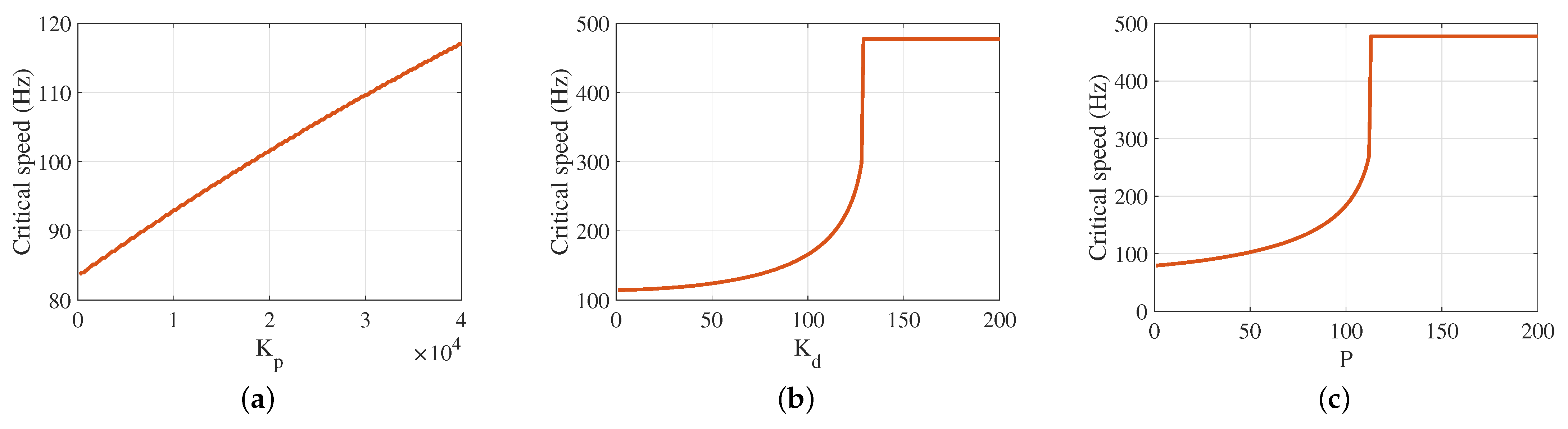
Combining the equivalent stiffness and damping expressions derived in Section 3.2 (Equations (22) and (23)), it follows that adjusting k p and k d directly modifies the system’s equivalent stiffness and damping, thereby altering the critical speed. Based on this mechanism, variable stiffness simulations were performed within the determined PD parameter range to analyze k p and k d effects on the critical speed. Figure 12 shows the following: with k d fixed, the critical speed increases linearly with k p (a 39.7% rise as k p increases from 2 × 10 2 to 4 × 10 4 ); with k p fixed, it grows geometrically with k d (a 317.2% increase as k d rises from 1 to 200); and with k p and k d increasing proportionally ( k p : k d = 200 : 1 ), it also exhibits geometric growth. Note that this simulation was conducted on a coupled system, solely to verify the effectiveness of dynamic stiffness adjustment. For a decoupled system, precise control of each channel enables superior dynamic stiffness adjustment performance.

4.2.3. Supercritical Speed Stage

This section aims to verify the gyroscopic effect suppression performance of the strategy combining decoupling and PD control in the supercritical stage, and to compare its steady-state accuracy with that of the PD control integrated with CFC.
First, the setpoint tracking simulation is conducted. The k p and k d of the PD controller are set to 2 × 10 4 and 2 × 10 2 , respectively. The results of the setpoint tracking simulation are shown in Figure 13 and Figure 14. The average error of the coupled system exceeds 20 μm, while the average error of the decoupling system in this paper is only 0.027 μm, with an accuracy improvement of over 99.85%. Although the traditional CFC can partially suppress the gyroscopic effect, it cannot eliminate structural coupling and still has obvious channel interference.
The simulation results of the initial disturbance suppression are shown in Figure 15. The average error of the coupled system is 5.9 μm, and the control current exceeds the 3.6 A limit (which is restricted by the power amplifier of this system); the average error of the decoupled system in this paper is 0.74 μm, with an accuracy improvement of 87.39%, and the control current does not exceed the limit, resulting in lower energy consumption. This is because decoupling eliminates the gyroscopic effect and structural coupling, allowing the controller to precisely act on the target channel and avoiding unnecessary energy consumption.

4.2.4. Global Performance Verification in the Entire Speed Range

This subsection aims to verify the vibration suppression effect of the scheme combining decoupling and full-speed range segmented control proposed in this paper across the entire speed range of 100–20,000 rpm, and to compare its global performance with the traditional scheme combining coupling, fixed PD control, and CFC. The test conditions are designed as follows:
(1)
Speed scanning: Uniform speed scanning from 100 to 20,000 rpm with a 50 rpm step.
(2)
Control strategies: The scheme proposed in this paper, which combines decoupling, subcritical unbalance compensation, critical CVSC, and supercritical fixed PD control; and the traditional scheme, which combines coupling, unbalance compensation, fixed PD control, and CFC.
(3)
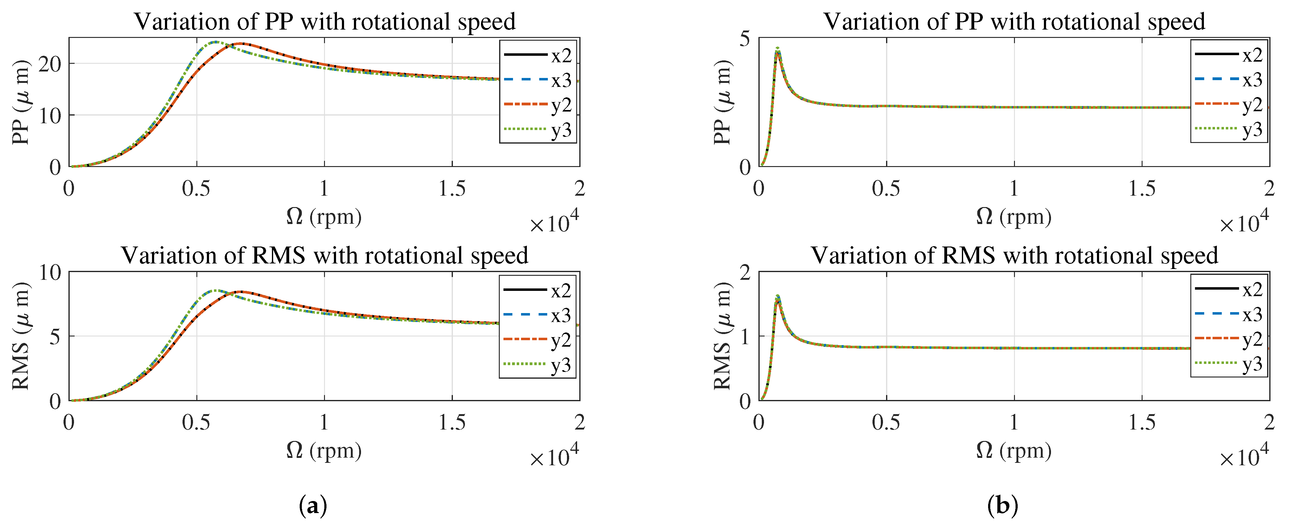
Evaluation indicators: Peak-to-peak (PP) vibration and root mean square vibration (RMS), with data extracted from the final 1 3 of the steady-state phase to exclude transition process interference.
The simulation results of the vibration characteristics in the full-speed range are shown in Figure 16. The comprehensive critical speed of the traditional scheme is 6236 rpm, with the maximum PP values in the x 2 and x 3 directions at the critical point being 23.83 μm and 24.13 μm respectively; the comprehensive critical speed of the scheme proposed in this paper is 750 rpm (owing to the decoupling and separation of low-order independent modes, the true low-order natural frequencies are revealed), and the maximum PP value at the critical point is only 4.40 to 4.60 μm. Throughout the entire speed range, the PP and RMS values of the vibration of the scheme proposed in this paper are significantly lower than those of the traditional scheme. The PP values of the four degrees of freedom vibration are reduced by more than 80%, with an average reduction of 81.23%.
The reduction of the comprehensive critical speed of the decoupled system compared to the coupled system is mainly due to the fact that decoupling directly alters the modal characteristics of the system (separating coupled modes and revealing the true natural frequencies of low-order independent modes) and the dynamic response mechanism, eliminating the influence of multi-channel coupling interference on control accuracy and transforming the system from a “coupled multi-modal” operating state to an “approximately independent single-modal” operating state. The core function of active decoupling is to effectively offset the internal coupling effects of the system through control compensation strategies. It does not change the inherent properties of the modes themselves, but separates the coupled and superimposed modal components, so that the true natural frequencies of the low-order independent modes can be revealed (corresponding to a critical speed of 750 rpm), thereby leading to a significant shift in the critical speed exhibited by the system. Specifically, in the coupled state, the system has three types of strong coupling effects: structural coupling, gyroscopic coupling, and translational–torsional coupling. These coupling effects will suppress the performance of low-order independent modes, making the dynamic characteristics of the system dominated by high-order coupled modes; hence, the corresponding critical speed shows a higher value (6236 rpm).

4.3. Active and Passive Synergistic Verification

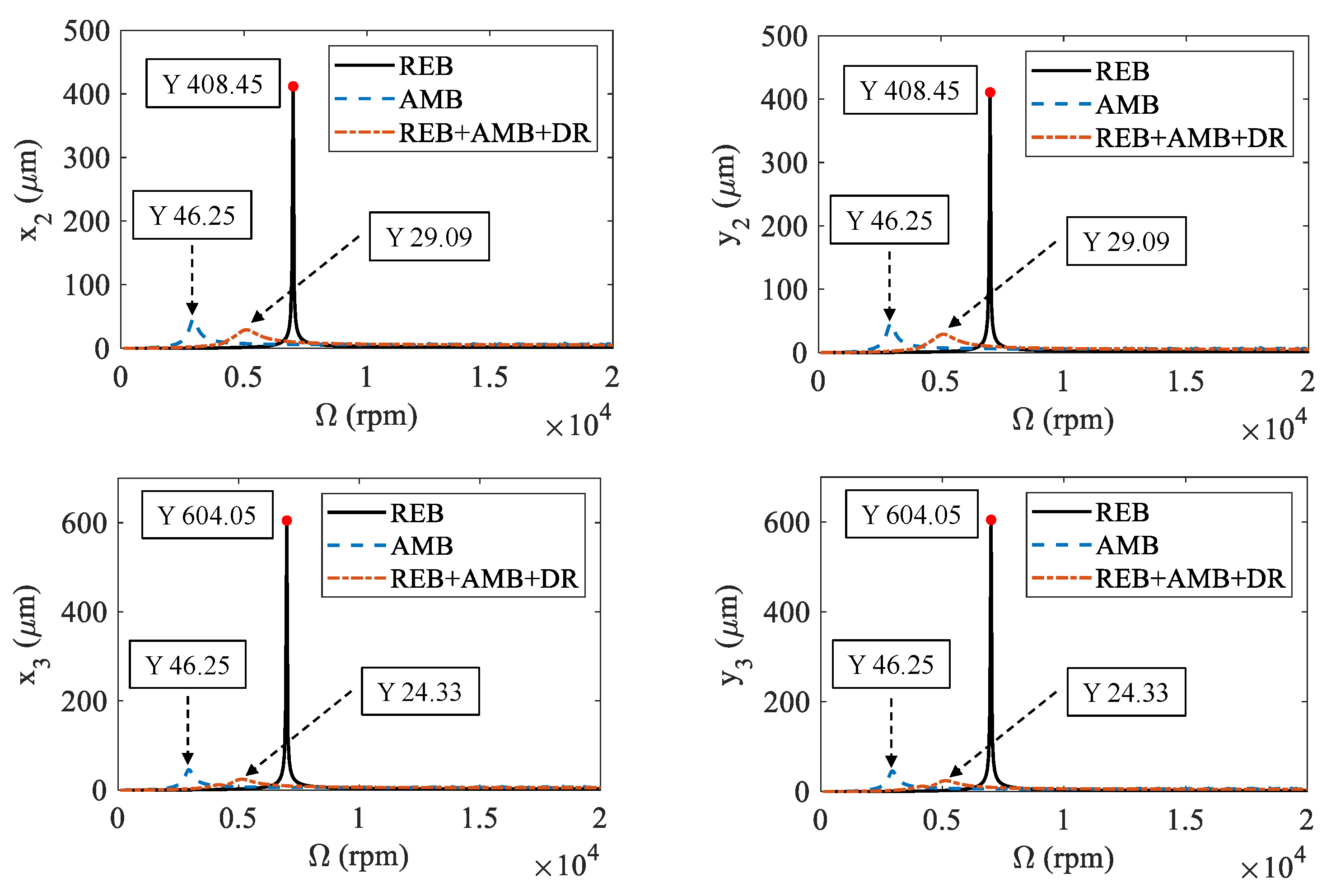
This section aims to verify the vibration reduction advantages of the active–passive synergistic support architecture combining mechanical bearings, magnetic bearings, and DR, by comparing its performance with that of the single support architectures featuring only mechanical bearings and only magnetic bearings. With an unbalanced mass of 5 × 10 5 kg·m, the vibration comparison results of different support architectures are shown in Figure 17. The system with only mechanical bearings experiences a strong resonance at 7000 rpm, with an average peak of 506.25 μm; the system with only magnetic bearings resonates at 2950 rpm, with an average peak of 46.25 μm; the active and passive synergistic support system proposed in this paper resonates at 5100 rpm, with a peak of only 26.71 μm, which is 94.72% and 42.25% lower than the previous two, respectively. The advantages of active and passive synergy lie in: mechanical bearings providing basic load-bearing capacity and ensuring structural stability; magnetic bearings adjusting stiffness/damping in real time through active control to suppress dynamic vibration; DRs offering additional passive damping to dissipate resonance energy, thereby synergistically enhancing the vibration reduction effect. The combination of the three achieves a synergistic optimization of “load bearing-active control-passive energy dissipation”, breaking through the performance bottleneck of single support architectures.

4.4. Robustness Verification

This section aims to verify the robustness of the decoupled control system proposed in this paper under the combined interference of current disturbance and parameter perturbation, and to compare its anti-interference ability with that of the coupled system. When the working speed is 9000 rpm, the proportional gain k p and derivative gain k d of the PD controller are set to 2 × 10 4 and 1 × 10 2 , respectively. The compound interference is as follows: At 0.1 s, a cosine disturbance current of 0.05 A and 10 Hz is injected in the x 2 direction of the upper electromagnetic bearing, and a sinusoidal disturbance current of the same amplitude is injected in the y 2 direction. At 0.2 s, the current stiffness coefficient k i in the x 3 and y 3 directions drops by 20%, simulating the perturbation of the electromagnetic bearing model. The robustness simulation results are shown in Figure 18. The average error of the convergence stage of the coupled system under compound interference is 7.06 to 7.20 μm. The average error of the decoupling system in this paper is 1.20 to 2.41 μm, and the accuracy improvement range is 66.55% to 82.93%, with an average improvement of 75.89%. The anti-interference advantage of the decoupling system stems from two key mechanisms. First, decoupling eliminates inter-channel coupling interference, confining disturbances to the target channel alone and preventing their diffusion and amplification. Second, the linearization characteristics of inverse system decoupling mitigate the impact of model perturbation on control accuracy, thereby enhancing the system’s adaptability to parameter uncertainties.
The invertibility of the inverse system serves as the fundamental premise for the implementation of decoupling control, which is guaranteed by the non-singularity of the Jacobian matrix. In this paper, the rigorous verification of system invertibility is completed by proving that the determinant of the Jacobian matrix is non-zero when the current stiffness coefficient k i 0 . Numerical robustness, in contrast, refers to the retention capability of invertibility under the conditions of parameter perturbation and external disturbance, which characterizes the engineering property that the decoupling algorithm can still maintain system invertibility and ensure decoupling accuracy when system parameters fluctuate, forming a core logical relationship of “fundamental premise-engineering extension”between the two. The core parameters affecting decoupling quality are sorted in the order of influence from high to low, and their action mechanisms are clarified as follows: the current stiffness coefficient k i , as the core parameter of decoupling control, directly determines the determinant value of the Jacobian matrix; the perturbation of k i will directly increase the risk of Jacobian matrix singularity and greatly reduce decoupling accuracy, making it the most critical factor affecting the invertibility and control accuracy of decoupling. The polar moment of inertia J p is the core characterization parameter of the gyroscopic effect coupling term under high-speed operating conditions; the perturbation of J p will lead to a decrease in the compensation accuracy of the gyroscopic coupling term, and the impact of its fluctuation on decoupling accuracy will be further highlighted at supercritical speeds. The displacement stiffness coefficient k x directly affects the modeling accuracy of electromagnetic force, thereby changing the design of the compensation term of the inverse system; the perturbation of this parameter will indirectly reduce the compensation effect of the decoupling algorithm and lead to a decrease in decoupling accuracy. The stiffness/damping coefficient of the DR, as the dynamic parameter of the passive support of the system, affects the damping performance of each independent subsystem after decoupling by indirectly changing the overall dynamic characteristics of the system, and has only a slight impact on decoupling accuracy, thus being classified as a secondary influencing parameter.

5. Discussion

This study addresses the full-speed vibration control challenge of active–passive supported FESS, proposing an integrated scheme combining DR-based active–passive architecture, inverse system 4-DOF full decoupling, and segmented full-speed control. Its core achievements and academic value are as follows. Firstly, the inverse system decoupling algorithm eliminates radial 4-DOF coupling by compensating structural and gyroscopic effects, simplifying controller design without cross-feedback channels. It overcomes traditional cross-feedback control defects, improving steady-state accuracy by 57% to 99.86% versus coupled systems, and limiting supercritical control current within 3.6 A to avoid over-limit bottlenecks. Secondly, the segmented full-speed strategy adapts to speed-dependent dynamic characteristics: subcritical low-frequency vibration is suppressed via decoupling and unbalance compensation; critical resonance is avoided by continuous variable stiffness control; supercritical gyroscopic instability is mitigated via decoupling. It reduces full-speed (100–20,000 rpm) average vibration PP by 81.23%, with the critical resonance peak dropping from 24.13 μm to 4.40 μm. Thirdly, the DR-integrated architecture realizes “load-bearing-active control-passive energy dissipation”synergy. Mechanical bearings ensure stability, AMBs regulate stiffness/damping, and DRs dissipate resonance energy, reducing critical peaks by 94.72% (vs. mechanical bearings) and 42.25% (vs. magnetic bearings).
Limitations include constrained AMB stiffness/damping adjustment by 3.6 A current limit, imperfect speed-stage linear transition under sudden changes, and model inaccuracy from unconsidered torsional vibration and temperature drift. This study mainly targets the specific dynamic characteristics of the active–passive hybrid support configuration and proposes an integrated scheme of inverse system decoupling and segmented control. Although robust methods such as sliding mode control and ADRC have exhibited excellent performance in pure magnetic suspension systems [29], their adaptability to active–passive hybrid systems has not been sufficiently investigated. Future work will systematically carry out comparative studies between inverse system decoupling and various advanced control methods, and explore the hierarchical architecture design of a decoupling layer combined with a robust control layer.

6. Conclusions

This paper focuses on the problem of full-speed range vibration control in the active and passive support FESS, and conducts dynamic modeling, decoupling algorithm design, segmented control strategy development, and simulation verification work. An integrated scheme incorporating active–passive cooperative architecture with DR, inverse system-based 4-DOF full decoupling, and full-speed range segmented control is proposed. The core conclusions are as follows.
(1) A radial 4-DOF dynamic model for the active and passive support FESS was established, accurately characterizing the dynamic characteristics of structural coupling, gyroscopic effect coupling, and unbalanced excitation, providing a precise modeling basis for subsequent decoupling and control design.
(2) The proposed inverse system decoupling algorithm achieves complete decoupling of radial 4-DOF, effectively eliminating static structure coupling and dynamic gyroscopic effect coupling. After decoupling, there is no cross-interference in each channel of the system. The steady-state average error of the setpoint tracking is reduced from 19.86 μm to 0.027 μm, and the accuracy is improved by 99.86%. The steady-state average error of initial disturbance suppression decreased from 5.48 μm to 1.14 μm, with an average decrease of 79.19%, which was significantly better than the traditional coupled system.
(3) The full-speed range segmented control strategy is designed to be adapted to the dynamic characteristics of each speed stage, achieving stable operation across the entire speed range from 100 to 20,000 rpm. The average resonant peak at the critical speed was reduced from 23.98 μm to 4.5 μm, and the average peak value of the vibration was weakened by 81.23%. This successfully solved the core problem of vibration amplification beyond the critical speed in the traditional fixed control strategy.
(4) The proposed active and passive cooperative support architecture with DRs has significant vibration reduction advantages. The average critical resonance peak is 94.72% lower than that of the mechanical bearing system alone (506.25 μm) and 42.25% lower than that of the magnetic bearing system alone (46.25 μm), achieving a coordinated optimization of “load bearing-active control-passive energy consumption”.
(5) The control scheme proposed in this paper has excellent robustness. Under the combined interference of current disturbance and parameter perturbation, the steady-state error is reduced by an average of 75.89% compared with the coupled system, and it is feasible for engineering application.


Author Contributions

Conceptualization, K.L.; Data curation, M.H.; Funding acquisition, Y.Z.; Investigation, M.H.; Methodology, experiment and measurement, M.H., D.L. and H.L.; Software, M.H. and Y.Z.; Validation, M.H.; Writing—original draft, M.H.; Writing—review and editing, K.L., J.W. and Y.Z. All authors have read and agreed to the published version of the manuscript.

Funding

This work is supported by the Hunan Provincial Natural Science Foundation of China (2026JJ81620).

Institutional Review Board Statement

Not applicable.

Informed Consent Statement

Not applicable.

Data Availability Statement

The data presented in this study are available on request from the corresponding author.

Acknowledgments

We would like to express our sincere gratitude to Weiya Zhou and Jinzhao Yang for their valuable help in framing the paper.

Conflicts of Interest

The authors declare no conflicts of interest.

Abbreviations

The following abbreviations are used in this manuscript:
FESSFlywheel energy storage system
PMBPermanent magnet bearing
AMBActive magnetic bearing
AHBActive hybrid bearing
CREMBCombined rolling element and magnetic bearing
REBRolling element bearing
DRDamping ring
m r Mass of the flywheel rotor
m 1 Mass of the upper damping ring after filling
m 2 Mass of the lower damping ring after filling
k 1 Stiffness of upper damping ring
k 2 Stiffness of the upper mechanical bearing
k 3 Stiffness of the lower mechanical bearing
k 4 Stiffness of lower damping ring
c 1 Damping coefficient of upper damping ring
c 4 Damping coefficient of lower damping ring
J p Polar moment inertia of the flywheel rotor
JDiameter moment inertia of the flywheel rotor
l 1 Length from upper mechanical bearing to upper end of flywheel
l 2 Length from lower mechanical bearing to lower end of flywheel
l 3 Length between the upper and lower ends of the flywheel
Ω Rotating speed of the rotor
ω Modal frequency or exciting frequency
xVibration in the direction of x-axis
yVibration in the direction of y-axis

References

  1. Zheng, Z.; Cai, D.; Bamisile, O. Optimization strategy for braking energy recovery of electric vehicles based on flywheel/battery hybrid energy storage system. J. Energy Storage 2024, 103, 114447. [Google Scholar] [CrossRef] [Scilit]
  2. Vernekar, N.K.; Pai, R.; Aroor, G.; Kumar, N.; Hariharan, G. Advancements in Active Journal Bearings: A Critical Review of Performance, Control, and Emerging Prospects. Modelling 2025, 6, 97. [Google Scholar] [CrossRef] [Scilit]
  3. Xu, K.; Guo, Y.; Lei, G.; Zhu, J. A Review of Flywheel Energy Storage System Technologies. Energies 2023, 16, 6462. [Google Scholar] [CrossRef] [Scilit]
  4. Farrokhzad Ershad, N.; Tafazzoli Mehrjardi, R.; Ehsani, M. High-performance 4WD electric powertrain with flywheel kinetic energy recovery. IEEE Trans. Power Electron. 2021, 36, 772–784. [Google Scholar] [CrossRef] [Scilit]
  5. Zhang, W.; Gu, X.; Ji, H. Robust Sensorless Control of Vehicle-mounted Flywheel Battery Against Continuous Road Disturbance. IEEE Trans. Transp. Electrif. 2025, 11, 12052–12062. [Google Scholar] [CrossRef] [Scilit]
  6. Hu, H.; Wei, J.; Wang, H.; Xiao, P.; Zeng, Y.; Liu, K. Analysis of the Notch Filter Insertion Position for Natural Frequency Vibration Suppression in a Magnetic Suspended Flywheel Energy Storage System. Actuators 2023, 12, 22. [Google Scholar] [CrossRef] [Scilit]
  7. Haidl, P.; Buchroithner, A. Design of a Low-Loss, Low-Cost Rolling Element Bearing System for a 5 kWh/100 kW Flywheel Energy Storage System. Energies 2021, 14, 7195. [Google Scholar] [CrossRef] [Scilit]
  8. Hu, H.; Liu, K.; Wang, H.; Wei, J. A wide bandwidth GaN switching power amplifier of active magnetic bearing for a flywheel energy storage system. IEEE Trans. Power Electron. 2023, 38, 2589–2605. [Google Scholar] [CrossRef] [Scilit]
  9. Buchroithner, A.; Brandstatter, A.; Recheis, M. Mobile Flywheel Energy Storage Systems: Determining Rolling Element Bearing Loads to Expand Possibilities. IEEE Veh. Technol. Mag. 2017, 12, 83–94. [Google Scholar] [CrossRef]
  10. Cole, M.; Hawkins, L. Model-Based Analysis of Friction-Induced Subsynchronous Whirl for a Rotor Contacting with Clearance Bearings Under Axial Load. ASME J. Eng. Gas Turbines Power 2016, 138, 072507. [Google Scholar] [CrossRef] [Scilit]
  11. Breńkacz, Ł.; Witanowski, Ł.; Drosińska-Komor, M.; Szewczuk-Krypa, N. Research and applications of active bearings: A state-of-the-art review. Mech. Syst. Signal Process. 2021, 151, 107423. [Google Scholar] [CrossRef] [Scilit]
  12. Kang, X.; Palazzolo, A. Simulation, Test, and Mitigation of ½× Forward Whirl Following Rotor Drop Onto Auxiliary Bearings. ASME J. Eng. Gas Turbines Power 2020, 142, 041020. [Google Scholar] [CrossRef] [Scilit]
  13. Haidl, P.; Zisser, M.; Buchroithner, A.; Schweighofer, B.; Wegleiter, H.; Bader, M. Improved Test Rig Design for Vibration Control of a Rotor Bearing System. In Proceedings of the 23rd International Congress on Sound and Vibration, Athens, Greece, 10–14 July 2016. [Google Scholar]
  14. Buchroithner, A.; Haan, A.; Preßmair, R.; Bader, M.; Schweighofer, B.; Wegleiter, H.; Edtmayer, H. Decentralized low-cost flywheel energy storage for photovoltaic systems. In Proceedings of the International Conference on Sustainable Energy Engineering and Application (ICSEEA), Jakarta, Indonesia, 3–5 October 2016. [Google Scholar]
  15. Passenbrunner, J.; Jungmayr, G.; Amrhein, W. Design and Analysis of a 1D Actively Stabilized System with Viscoelastic Damping Support. Actuators 2019, 8, 33. [Google Scholar] [CrossRef] [Scilit]
  16. Tao, Y.; Tohti, G.; He, H.; Geni, M. Study on the Dynamic Optimization and Design of a Flexible Rotationally Symmetric Tangential Support Plate Base. Appl. Sci. 2025, 15, 2554. [Google Scholar] [CrossRef] [Scilit]
  17. Hu, M.; Liu, K.; Wei, J.; Hou, E.; Liu, D.; Zhao, X. Dynamics Study of Hybrid Support Flywheel Energy Storage System with Damping Ring Device. Actuators 2024, 13, 532. [Google Scholar] [CrossRef] [Scilit]
  18. Filatov, A.V.; Maslen, E.H. Passive Magnetic Bearing for Flywheel energy storage systems. IEEE Trans. Magn. 2001, 37, 3913–3924. [Google Scholar] [CrossRef]
  19. Fang, J.; Le, Y.; Sun, J.; Wang, K. Analysis and Design of Passive Magnetic Bearing and Damping System for High-Speed Compressor. IEEE Trans. Magn. 2012, 48, 2528–2537. [Google Scholar] [CrossRef] [Scilit]
  20. Vigliani, A.; Cavallaro, S.P.; Venturini, S. Modelling and Experimental Testing of Passive Magnetic Bearings for Power Loss Reduction. Appl. Sci. 2025, 15, 4149. [Google Scholar] [CrossRef] [Scilit]
  21. Fang, J.; Tang, E.; Zheng, S. Optimum Damping Control of the Flexible Rotor in High Energy Density Magnetically Suspended Motor. ASME J. Eng. Gas Turbines Power 2015, 137, 082505. [Google Scholar] [CrossRef] [Scilit]
  22. Sato, D.; Itoh, J.; Watanabe, T.; Kawagoe, K.; Yamada, N.; Kato, K. Development of magnetic coupling with variable thrust structure for flywheel energy storage system in long lifetime UPS. In Proceedings of the IEEE International Telecommunications Energy Conference (INTELEC), Osaka, Japan, 18–22 October 2015. [Google Scholar]
  23. Yang, D.; Qin, H.; Xie, X.; Zhang, Z. Suppression of lateral vibration in a shafting system via an auxiliary active magnetic bearing with position control. Proc. Inst. Mech. Eng. Part C J. Mech. Eng. Sci. 2023, 237, 1581–1594. [Google Scholar] [CrossRef] [Scilit]
  24. Recheis, M.; Buchroithner, A.; Andrasec, I.; Gallien, T.; Schweighofer, B.; Bader, M.; Wegleiter, H. Improving kinetic energy storage for vehicles through the combination of rolling element and active magnetic bearings. In Proceedings of the IECON 2013—39th Annual Conference of the IEEE Industrial Electronics Society, Vienna, Austria, 10–13 November 2013. [Google Scholar]
  25. Okada, Y.; Nagai, B.; Shimane, T. Cross-feedback stabilization of the digitally controlled magnetic bearing. J. Vib. Acoust. Stress. Reliab. Des. 1992, 114, 54–59. [Google Scholar] [CrossRef] [Scilit]
  26. Jana, A. Differential geometry-based adaptive nonlinear control law: Application to an industrial refinery process. IEEE Trans. Ind. Inform. 2013, 9, 2014–2022. [Google Scholar] [CrossRef] [Scilit]
  27. Lu, W.; Li, C.; Xu, C. Sliding mode control of a shunt hybrid active power filter based on the inverse system method. Int. J. Electr. Power Energy Syst. 2014, 57, 39–48. [Google Scholar] [CrossRef] [Scilit]
  28. Lu, C.; Cheng, J.; Ding, Q.; Zhang, G.; Fang, J.; Zhang, L.; Du, C.; Zhang, Y. Inverse System Decoupling Control of Composite Cage Rotor Bearingless Induction Motor Based on Support Vector Machine Optimized by Improved Simulated Annealing-Genetic Algorithm. Actuators 2025, 14, 125. [Google Scholar] [CrossRef] [Scilit]
  29. Lu, J.; Ye, C.; Wan, S. Improved active disturbance rejection control for AMB flywheel system based on inverse system. Int. J. Dyn. Control 2024, 12, 1086–1097. [Google Scholar] [CrossRef] [Scilit]
  30. Sun, X.; Su, B.; Chen, L. Precise control of a four degree-of-freedom permanent magnet biased active magnetic bearing system in a magnetically suspended direct-driven spindle using neural network inverse scheme. Mech. Syst. Signal Process. 2017, 88, 36–48. [Google Scholar] [CrossRef] [Scilit]
  31. Fang, J.; Ren, Y. Decoupling control of magnetically suspended rotor system in control moment gyros based on an inverse system method. IEEE/ASME Trans. Mechatron. 2011, 17, 1133–1144. [Google Scholar] [CrossRef] [Scilit]
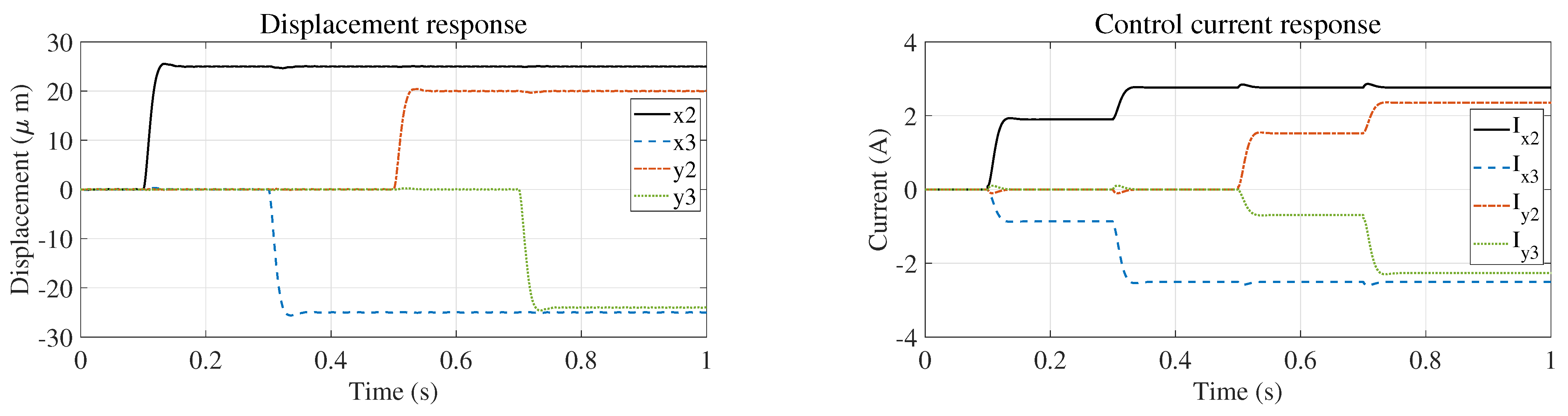
  32. Liu, H.; Mao, L.; Wang, T. Theoretical and experimental study on a dual-stage variable stiffness friction damper for satellite flywheel. Mech. Syst. Signal Process. 2023, 185, 109761. [Google Scholar] [CrossRef] [Scilit]
  33. Li, S.; Zhou, C.; Savin, L. Theoretical and experimental study of motion suppression and friction reduction of rotor systems with active hybrid fluid-film bearings. Mech. Syst. Signal Process. 2023, 182, 109548. [Google Scholar] [CrossRef] [Scilit]
  34. Morais, T.; Der Hagopian, J.; Steffen, V., Jr. Modeling and identification of electromagnetic actuator for the control of rotating machinery. Shock Vib. 2013, 20, 171–179. [Google Scholar] [CrossRef]
  35. Laine, S.; Haikonen, S.; Tiainen, T. Rotor resonance avoidance by continuous adjustment of support stiffness. Int. J. Mech. Sci. 2024, 270, 109092. [Google Scholar] [CrossRef] [Scilit]
  36. Wang, C.; Wang, S.; Li, Q. A novel adaptive control strategy for wide-speed-range aero-engine rotor systems with elastic support-dry friction dampers. Aerosp. Sci. Technol. 2025, 158, 109889. [Google Scholar] [CrossRef] [Scilit]
Figure 1. Schematic diagram of the structure of the FESS with active and passive supports.
Actuators 15 00157 g001
Figure 2. Dynamic model of the FESS with active and passive supports.
Actuators 15 00157 g002
Figure 3. Critical speeds of FESS under different supports (a) Active and passive supported FESS; (b) mechanical bearing FESS.
Actuators 15 00157 g003
Figure 4. Block diagram of traditional PD control with unbalance compensation principle.
Actuators 15 00157 g004
Figure 5. Block diagram of PD control based on inverse system decoupling with unbalance compensation principle.
Actuators 15 00157 g005
Figure 6. Coupling conditions of each degree of freedom in the coupled system.
Actuators 15 00157 g006
Figure 7. Coupling conditions of each degree of freedom after system decoupling.
Actuators 15 00157 g007
Figure 8. Subcritical setpoint tracking response of the coupled system.
Actuators 15 00157 g008
Figure 9. Subcritical setpoint tracking response of decoupled system.
Actuators 15 00157 g009
Figure 10. Comparison of initial disturbance suppression responses in the subcritical stage: (a) coupled system, (b) decoupled system.
Actuators 15 00157 g010
Figure 11. Three-level screening process of PD control parameter stability domain.
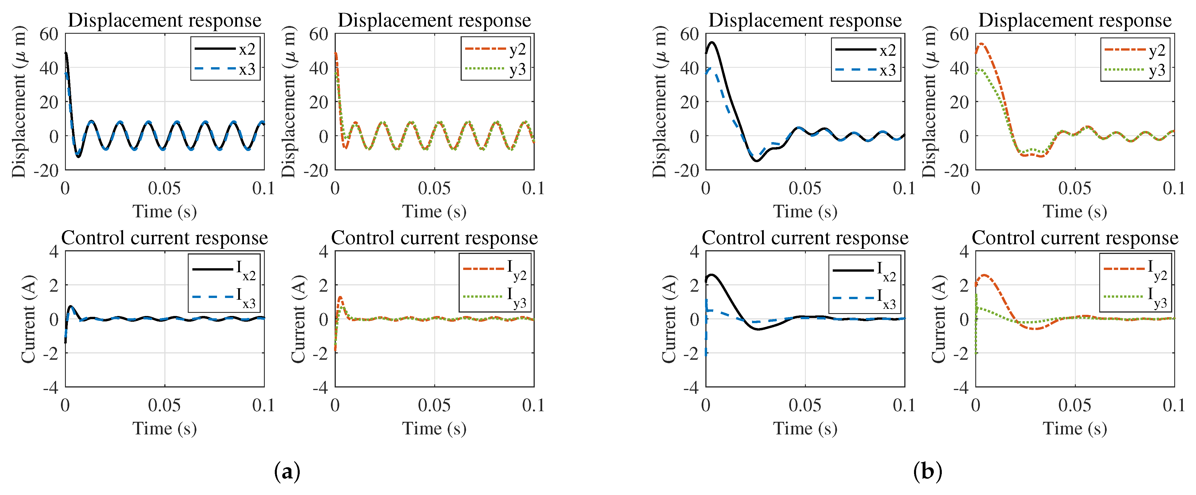
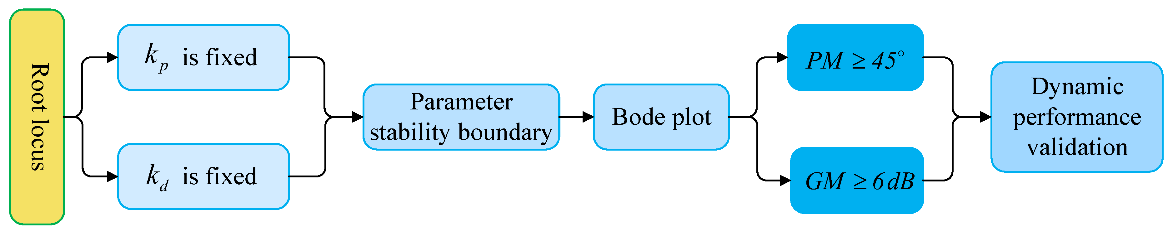
Actuators 15 00157 g011
Figure 12. Correlation characteristic curve of PD parameters and critical speed of the system: (a) k p , (b) k d , (c) P.
Actuators 15 00157 g012
Figure 13. Supercritical setpoint tracking response of the PD control integrated with CFC.
Actuators 15 00157 g013
Figure 14. Decoupled system supercritical setpoint tracking response.
Actuators 15 00157 g014
Figure 15. Comparison of initial disturbance suppression responses in the supercritical stage: (a) coupled system, (b) decoupled system.
Actuators 15 00157 g015
Figure 16. Comparison curve of PP and RMS values of vibration in the entire speed range: (a) coupled system, (b) decoupled system.
Actuators 15 00157 g016
Figure 17. Comparison of PP vibration values in the full-speed range for different support structures.
Actuators 15 00157 g017
Figure 18. Comparison of the responses of the two systems under compound interference: (a) coupled system, (b) decoupled system.
Actuators 15 00157 g018
Table 1. Structure and dynamic parameters of FESS.
ItemValueItemValueItemValueItemValue
m r (kg)41.34 m 1 (kg)0.198 m 2 (kg)0.117J (kg· m 2 )0.566
J p (kg· m 2 )0.835 l 1 (m)0.06 l 2 (m)0.052 l 3 (m)0.19
k 2 (N/m) 6.96 × 10 7 k 3 (N/m) 3.48 × 10 7 k 1 (N/m) 7.29 × 10 6 c 1 (N·s/m) 1.66 × 10 3
k 4 (N/m) 7.29 × 10 6 c 4 (N·s/m) 1.66 × 10 3 k x (N/m) 1.25 × 10 6 k i (N/A)140
Disclaimer/Publisher’s Note: The statements, opinions and data contained in all publications are solely those of the individual author(s) and contributor(s) and not of MDPI and/or the editor(s). MDPI and/or the editor(s) disclaim responsibility for any injury to people or property resulting from any ideas, methods, instructions or products referred to in the content.