


Abstract
The proportional integral derivative (PI) controller remains the predominant algorithm employed in engineering applications. Nevertheless, existing PI tuning methodologies, whether classical or contemporary, are often characterized by indirectness and limited accuracy or by excessive complexity that hinders practical implementation. Moreover, the influence of the noise filter incorporated within the feedback loop on the closed-loop system performance has not been comprehensively evaluated in these tuning strategies. Consequently, the resulting PI parameters frequently demonstrate suboptimal performance, necessitating empirical on-site adjustments through trial and error. To address these limitations, this study proposes a novel PI controller tuning approach that explicitly integrates the noise filter and directly designs the closed-loop system to meet specified bandwidth criteria. Additionally, the proposed method guarantees the absence of resonance peaks in the closed-loop amplitude frequency response and incorporates considerations of noise attenuation and phase margin. The efficacy and applicability of the method were validated experimentally on a permanent magnet synchronous motor (PMSM) servo system, confirming its practical utility.
1. Introduction
Permanent magnet synchronous motors (PMSMs) are extensively utilized in industries such as robotics, aerospace, and electric vehicles because of their excellent features, including high power density, strong reliability, and effective control performance. The most commonly employed control technique for PMSMs is the field-oriented cascaded PI control, valued for its simplicity and robustness.
Compared to other control methods, the PI controller has a long-standing history in automatic control systems. Initially, in 1788, James Watt applied proportional control to enhance the steam engine. Later, in 1868, Maxwell analyzed the stability of the governor through differential equations, demonstrating how parameters affect system dynamics and establishing the groundwork for control theory. By the early 20th century, classical PI control had evolved, incorporating integral and derivative components alongside proportional control to eliminate steady-state errors and reduce oscillations.
The initial design of PI controllers relied on a trial-and-error approach without theoretical guidance, making it time-consuming and dependent on experience. Nyquist and Bird introduced a frequency-domain analysis method that provided a stability criterion for parameter design; however, estimating closed-loop performance by designing the open-loop frequency response was indirect and imprecise, requiring repeated verification of the tuned parameters. Subsequently, the Ziegler–Nichols and Cohen–Coon methods were developed for parameter tuning [1,2,3], but these were limited to first- or second-order systems and could cause severe oscillations in higher-order or nonlinear systems [4]. PI controllers have since been widely adopted in engineering practice. Building on the original ideal control structure, design optimizations have been made to account for lag elements introduced during actual actuator operation and random environmental disturbances, aiming to better reflect real control performance [5,6]. References [7,8] applied the internal model control (IMC) approach for controller design and used an internal model PI tuning method based on the Maclaurin series for cascaded control systems. However, this method neglected higher-order terms of the Maclaurin series, resulting in inaccuracies. To improve control performance for nonlinear, time-delay, and large time constant systems, replacing the integral term in the traditional PI controller with a fractional order term can effectively balance overshoot and response speed. Nonetheless, designing and tuning fractional PI controllers is complex, computationally intensive, and often requires integration with advanced control algorithms [9,10,11].
Unlike conventional control methods that demand accurate system models, advancements in learning control have introduced intelligent algorithms like genetic algorithms [12], neural networks [13], and particle swarm optimization [14] for automatic parameter tuning [15]. Additionally, model-free predictive control, reinforcement learning, and other tuning techniques can eliminate reliance on system models entirely [16]. However, these adaptive algorithms require extensive online computation, making them impractical for engineering applications involving high-precision control systems with rapid control cycles [17,18].
In summary, traditional PI tuning methods, whether classical or modern, tend to be either indirect and imprecise or overly complex and difficult to implement. Additionally, none of these methods have thoroughly assessed how the noise filter in the feedback loop affects closed-loop performance. As a result, the PI parameters obtained often lead to suboptimal performance and require on-site trial-and-error adjustments. To address these issues, this paper proposes a new PI tuning approach for certain system types that directly targets the closed-loop bandwidth while considering factors such as resonance peaks, noise suppression, and phase margin. Furthermore, the paper reports on applying this tuning method to a PMSM servo system. The key contribution is offering a PI controller design method that is direct, accurate, and intuitive, and that incorporates the impact of the noise filter during parameter tuning.
The structure of the paper is as follows: Section 2 introduces the proposed tuning method; Section 3 details its application in designing a PI controller for a PMSM servo system; Section 4 presents simulation and experimental results to demonstrate the method’s feasibility and effectiveness; and Section 5 concludes the paper.
2. The Proposed Novel Tuning Method for PI Controller
For control plants with transfer functions of types (1), (2), or (3), one can obtain an I-type system by using a P, PI, or PID controller, respectively, through the application of the zero-pole cancellation technique.
where, is the gain of the plant, , and are time constants related to the system dynamics, and < is supposed for transfer function (2).
The corresponding P, PI and PID controllers are formulated as
where kp is the gain of the controller.
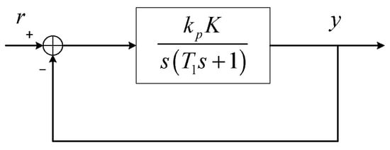
The resulting I-type system is expressed by Equation (7), and the related closed-loop control diagram is illustrated in Figure 1.
according to the frequency domain design principle, the asymptote must cross the 0 dB line with a slope of −20 dB per decade at the cutoff frequency.
Figure 1.
System control block diagram using PI controller.
The cut-off frequency is generally considered approximately equal to the closed-loop bandwidth. This leads to the approximate result shown in Equation (8).
based on Equations (4)–(6) and (8), the control parameters can be fully determined by the plant dynamics and the desired closed-loop bandwidth.
However, in real physical systems, the output signal is often contaminated by noise. Therefore, it is necessary to use a low-pass filter within the feedback loop. Unfortunately, this feedback filter introduces additional zeros and poles into the system’s closed-loop transfer function, which alters the system’s performance. Consequently, the filter must be considered during the controller tuning process.
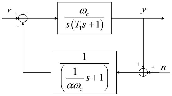
Let the filter’s bandwidth be set as a multiple of the cutoff frequency, with α > 0 always holding true. The closed-loop control system block diagram incorporating a first-order low-pass filter in the feedback loop is illustrated in Figure 2.
Figure 2.
System control block diagram with filter.
The system’s closed-loop transfer function can be derived as presented in Equation (9).
2.1. Design of System Bandwidth
The closed-loop bandwidth is defined by Equation (10). By substituting Equation (9) into Equation (10) and simplifying, the constraint relationship among the system bandwidth, the cut-off frequency, and the ratio coefficient α is derived, as presented in Equation (11).
in other words, when the system bandwidth is specified, ωc and α must fulfill the condition stated in Equation (11), and theoretically, there are infinitely many pairs of (ωc, α) that satisfy the system bandwidth criteria.
Additional conditions need to be introduced to further determinate the optimal set of (, ).
2.2. Resonance Peak Consideration
The resonance peak of the system is directly linked to the overshoot in the system’s dynamic response. A lower resonance peak corresponds to a smaller overshoot. Therefore, to minimize overshoot as much as possible, the closed-loop amplitude–frequency response must not exhibit any resonance peaks. This means that inequality (12) must be satisfied for all frequency values.
where
and it is necessary to ensure to comply with for all the frequency value .
According to Equation (13), it can be derived that
and further derivation leads to the constraints for and to meet the requirement of no resonance peaks, which is formulated as (15).
2.3. Noise Suppression Capability
The noise transfer function of the closed-loop system shown in Figure 2 is
The following equation displays the amplitude ratio between the noise transfer function and the closed-loop output transfer function.
since the closed-loop system has the same bandwidth and is free of resonant peaks.
The system is anticipated to exhibit roughly the same closed-loop amplitude frequency response for various parameter sets. From Equation (17), it is evident that a smaller ratio coefficient corresponds to better noise suppression. In other words, when the system output is significantly affected by noise, it is advisable to use a filter with a narrow bandwidth in the feedback loop, which aligns with intuitive understanding.
2.4. Phase Margin
The open loop transfer function of the system shown in Figure 2 is
As stated above, the asymptote of is expected to cross the 0 dB line with −20 dB/dec at .
So according to Equation (18), the phase margin of the system can be expressed as follows in approximation.
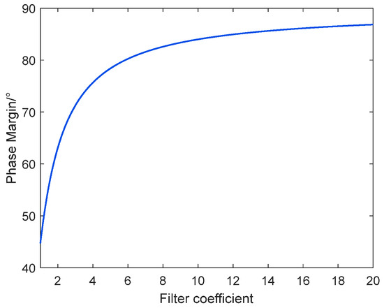
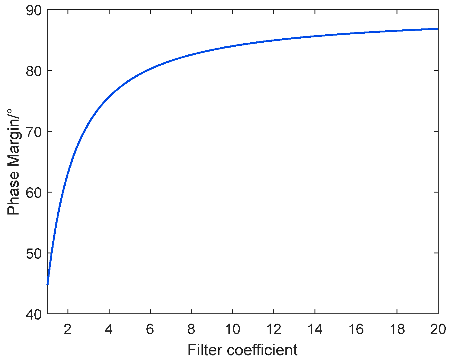
It can be observed that a smaller value helps enhance the system’s control accuracy. Under the same conditions of and, the relationship curve between γ and α is illustrated in Figure 3.
Figure 3.
The trend of phase margin variation with the ratio coefficient α.
On the other hand, the phase margin will decrease as well, making the system more likely to oscillate. Therefore, in a real system, a balance must be struck among various parameter settings, rather than focusing solely on maximizing noise suppression.
3. Design of PMSM Servo System Using the Proposed Tuning Method
In this section, the previously described PI controller tuning method is applied to the design of a PMSM servo system. The system specifications and PMSM parameters used are listed in Table 1.
Table 1.
System specifications and PMSM parameters.
The sensor employed in this study is a 26-bit absolute position imaging sensor. Within the servo system’s three-loop architecture, both the current loop and the position loop require position data for feedback and closed-loop control, whereas the speed loop derives velocity values by differentiating the position signals. However, the differentiation process can introduce sensor noise, which is approximately characterized as white noise. In the current loop, current measurement is performed using a 16-bit analog-to-digital converter (ADC), which similarly contributes a certain level of white noise. To mitigate the adverse effects of noise arising from the acquisition and computation of position, speed, and current signals on the precision of closed-loop control, low-pass filters are incorporated into each signal acquisition circuit. Furthermore, to ensure that these low-pass filters do not compromise system stability or bandwidth, their influence is carefully considered during the design of the proportional integral (PI) controller presented in this work, with optimal parameters selected based on a comprehensive evaluation of relevant factors.
3.1. Current Loop Design
The voltage equation of PMSM in the rotating frame is formulated as
where is the back electromotive force (EMF) of the motor, , are the stator voltage and current, respectively.
Ignoring the EMF, then the transfer function from to is deduced as
Considering the one step delay and sample-hold characteristic of the digital control system, the transfer function from control variable to output current is approximated as
Comparing Equation (22) with Equation (2), it can be concluded that , , and for the current loop.
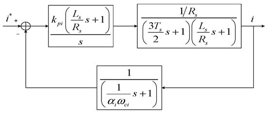
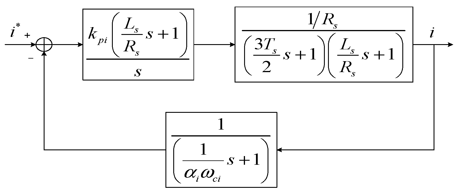
The control diagram of the current loop using PI controller is shown in Figure 4. The controller and filter is formulated as Equations (23) and (24), respectively.
where is the gain of the current PI controller. is the cut-off frequency of the asymptote of , and is the ratio of the current filter bandwidth to .
Figure 4.
Block diagram of the current loop.
According to the proposed tuning method and Equation (8), can be determined as
It can be seen from Equations (23)–(25) that the controller and filter is tuned as long as and are selected optimally.
However, the analytical solution of and cannot be deduced within the proposed tuning method framework, they are determined by adopting the numerical calculation method.
The closed-loop bandwidth of the current loop is given as 100 ± 0.5 Hz. Setting the cut-off frequency is within the range of 60–70 Hz with a step length of 2 Hz, and the ratio coefficient is with a step length 0.1. Following Equations (11) and (15), the parameter configurations that meet the closed-loop bandwidth and without resonant peaks are determined by adopting the numerical calculation method, which are shown in Table 2. Where is the filter bandwidth, and is the phase margin calculated following Equation (19).
Table 2.
The parameter combinations satisfying = 100 ± 0.5 Hz.
Table 2 shows that all configurations have an adequate phase margin, indicating that system stability is not an issue for the current loop. To improve noise suppression, the smallest value should be chosen according to Equation (17). In this sense, the current controller and filter is tuned as (26) and (27) by the determination of .
3.2. Speed Loop Design
In motor servo systems, the speed feedback signal is typically derived by differentiating the position signal. Taking into account the overall delay introduced by the differentiation process, the sample-and-hold behavior, and the current loop bandwidth, the transfer function relating the speed control input to the shaft speed is given by
where is the torque constant of the involved PMSM, and it relates to the pole pairs and rotor flux linkage as
Comparing Equation (28) with Equation (2), it can be concluded that , , and for the speed loop.
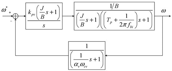
The control diagram of the speed loop with a PI controller and a low-pass filter is shown in Figure 5.
Figure 5.
Block diagram of the speed loop.
Following the similarly procedure of (23)–(25), and taking the closed-loop bandwidth of the speed loop as 20 ± 0.5 Hz, the partial parameter configurations that meet the bandwidth and resonance requirements are shown in Table 3.
Table 3.
The parameter combination satisfying .
The cut-off frequency is constrained within the range of 10–15 Hz with a step length of 1 Hz, and the coefficient ratio is set to have a step length of 0.1. The and are the corresponding filter bandwidth and phase margin, respectively.
Since the moment of inertia and viscous friction coefficient feature significant uncertainty, the speed loop should have sufficient phase margin. As and are selected, the speed controller and filter are tuned as
3.3. Position Loop Design
The closed-loop transfer function of the speed loop can be approximated as a first-order lag by neglecting higher-order dynamics. Considering the sample-and-hold effect, the transfer function of the position control plant is given by
According to the proposed tuning method, a P-type controller should be used to adjust the angular position output of the motor.
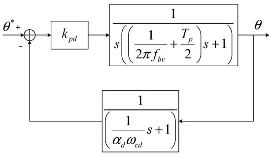
The control diagram of the position loop with a P-type controller and a low-pass filter is shown in Figure 6.
Figure 6.
Block diagram of the position loop.
The closed-loop bandwidth is expected, and , is determined through numerical calculation, and the corresponding phase margin is 67.3°. The resulting position controller and filter is shown as
4. Simulation and Experimental Results
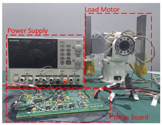
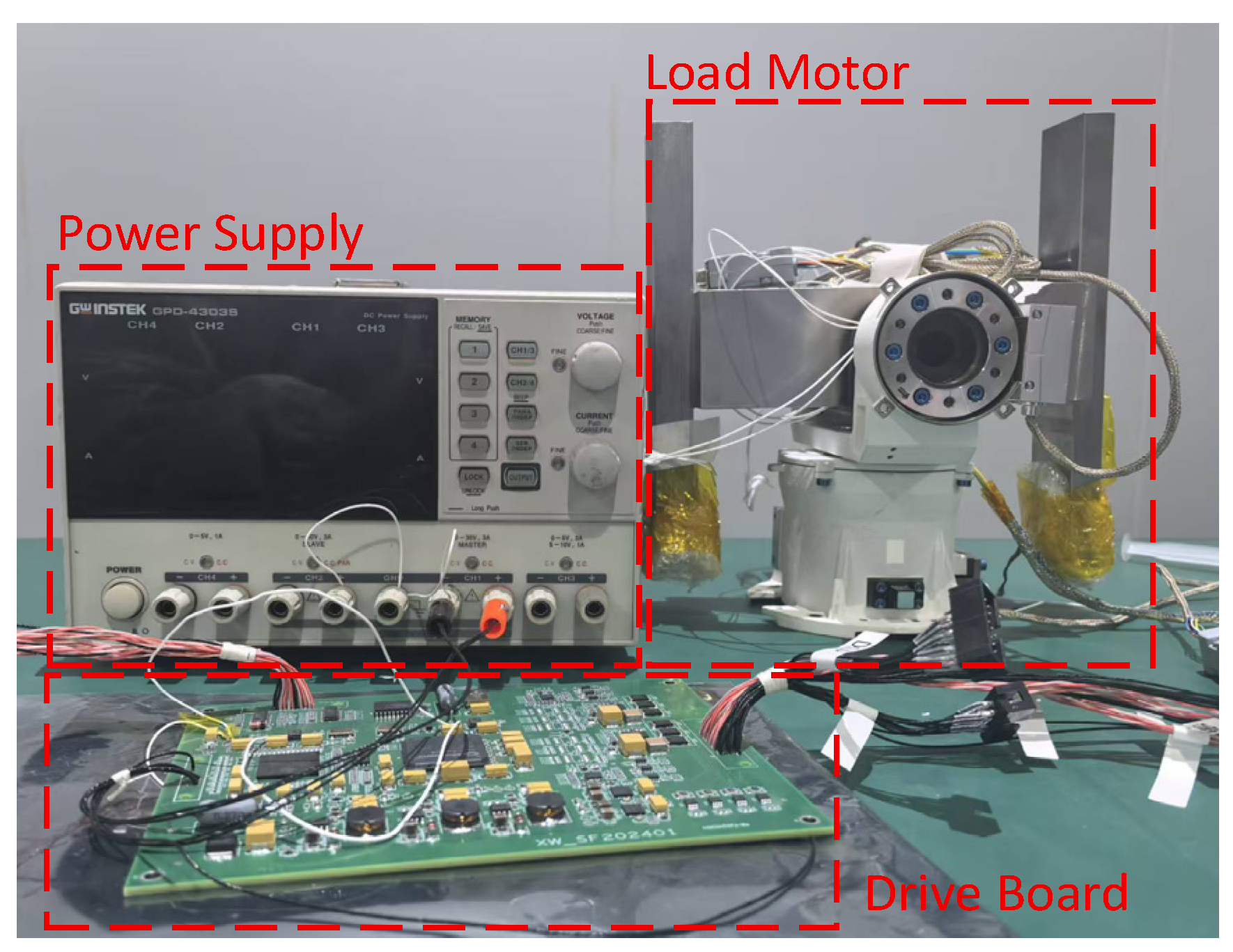
Following the previous design, PI controllers were developed for the current loop, speed loop, and position loop, respectively. Based on this, simulation models were created to simulate and validate the design approach presented in this paper, and an experimental setup was established for testing. The core of the experimental platform is a real-time control system built around the TI TMS570LS4357B. A 26-bit absolute encoder was chosen, and the PWM carrier frequency is set at 20 kHz. To confirm the accuracy of the proposed design method, both simulation and experiments were performed using the same parameters, as detailed in Table 1. The experimental platform is illustrated in Figure 7.
Figure 7.
Experimental setup.
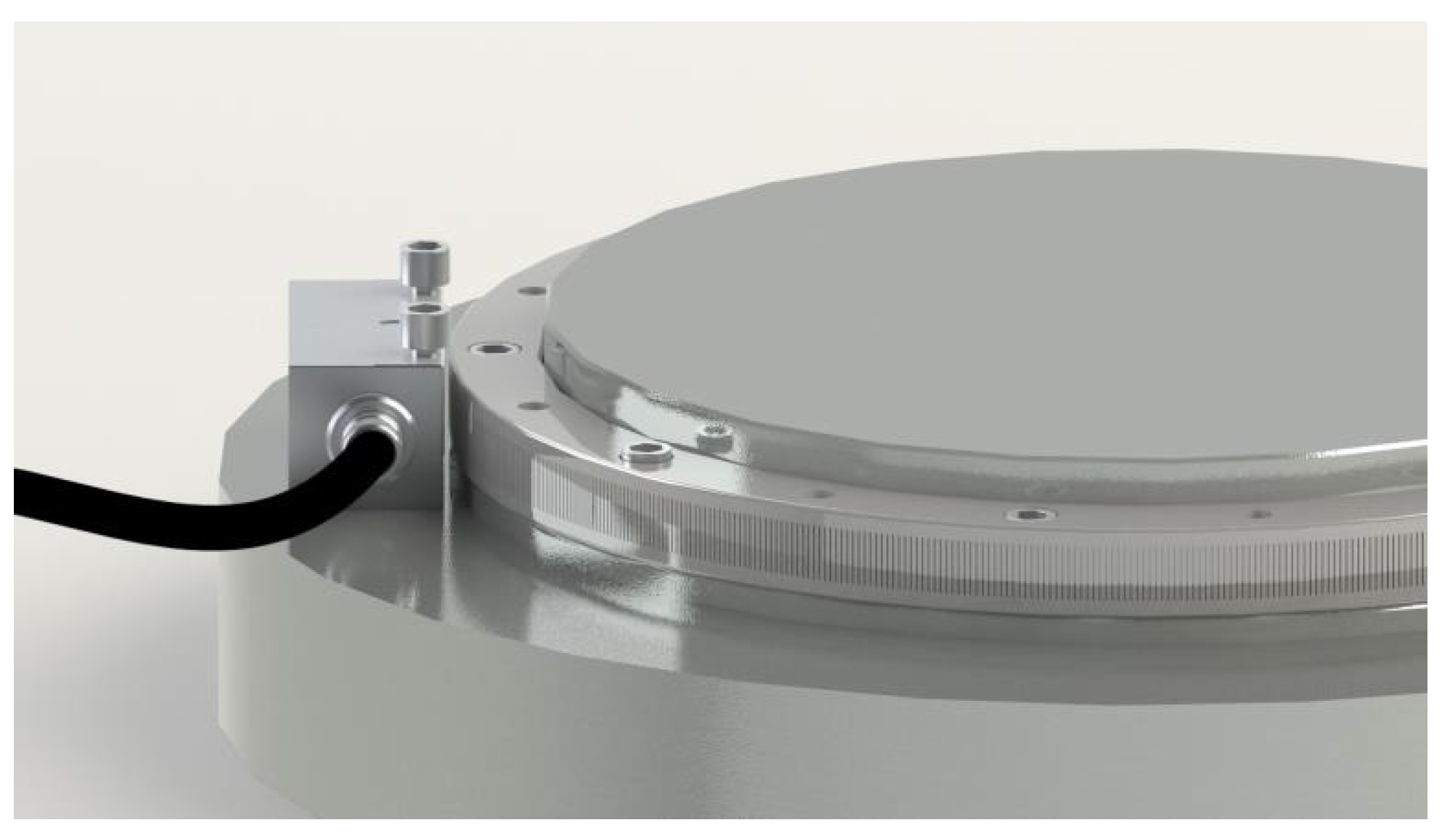
Based on the dimensional and precision requirements of the rotating shaft, this study utilizes a 26-bit imaging absolute position sensor. This sensor employs a signal super-resolution decoding technique to attain high-precision and compact angular measurement. The encoder features advantageous attributes including a large hollow shaft, lightweight construction, and low rotational inertia, rendering it well-suited for controlling turntables with hollow shaft configurations. Its split-type structural design enables direct attachment of the encoder disc to the rotating element, thereby minimizing measurement errors. The primary technical specifications are presented in Table 4, while its physical appearance is depicted in Figure 8.
Table 4.
Raster model parameters.
Figure 8.
Metal grating angle encoder.
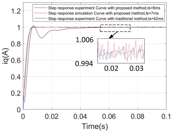
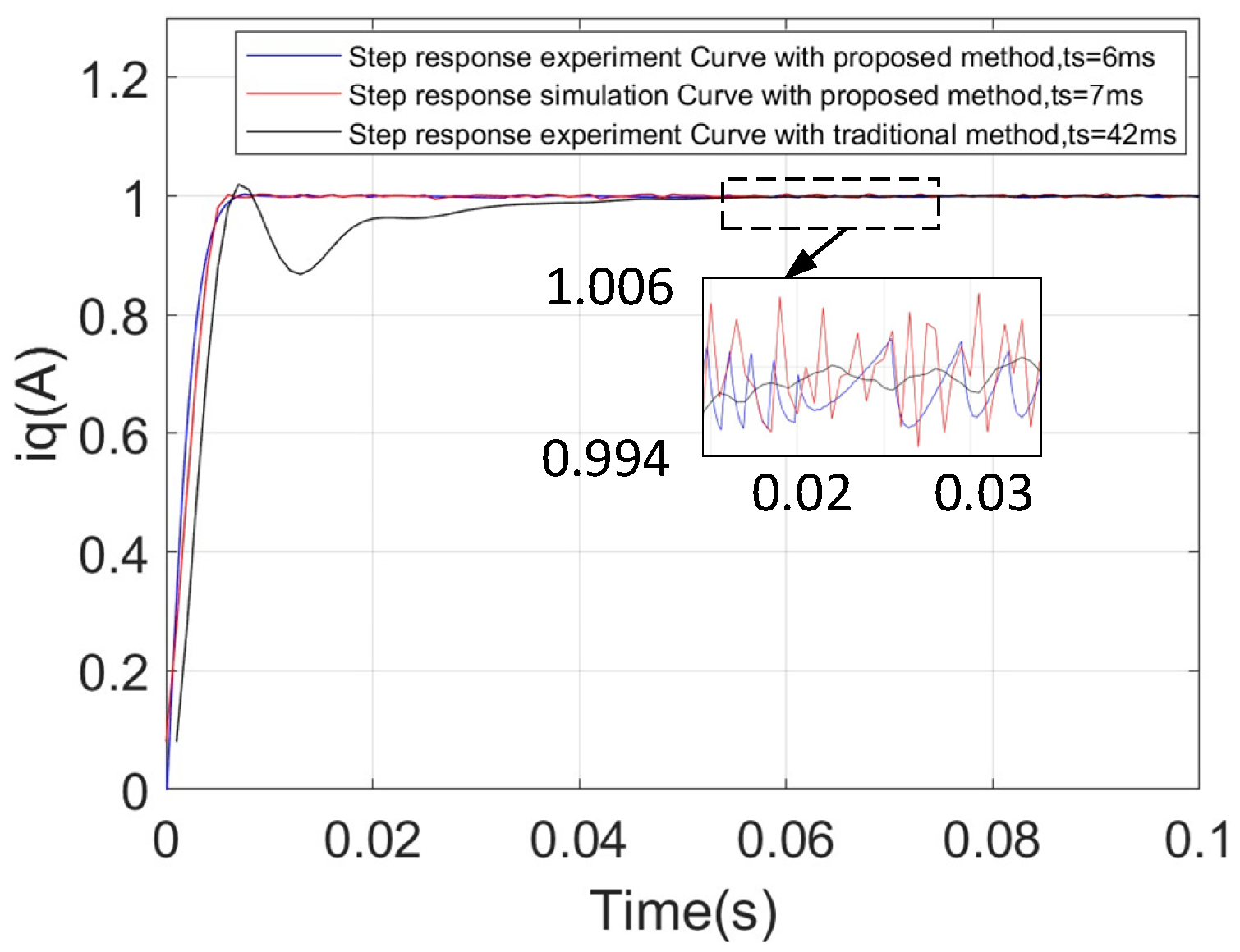
The servo system simulation model was developed using Matlab R2022b, and the step response curves of the current loop were generated, as illustrated in Figure 9. Analysis of the current loop response waveforms indicates that the response times for the simulation and experimental data are 7 ms and 6 ms, respectively. The maximum observed jitter in the experimental measurements is 0.0055 A, whereas the maximum jitter in the simulation is 0.0034 A. Overall, the simulation waveforms exhibit strong agreement with the experimental results.
Figure 9.
The current curve obtained by the proposed PI controller design method based on the dual-lag link system.
The current response of the current loop PID controller obtained by the traditional design method has overshoot, which proves that the parameters obtained by the traditional design method are inconsistent with the design expectations during the actual debugging process.
The current response of the current loop PID controller, derived using the conventional design approach, exhibits overshoot, indicating that the parameters obtained through this traditional method do not align with the design expectations during practical debugging.
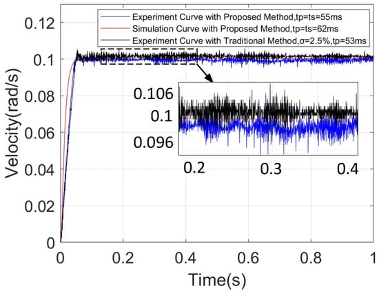
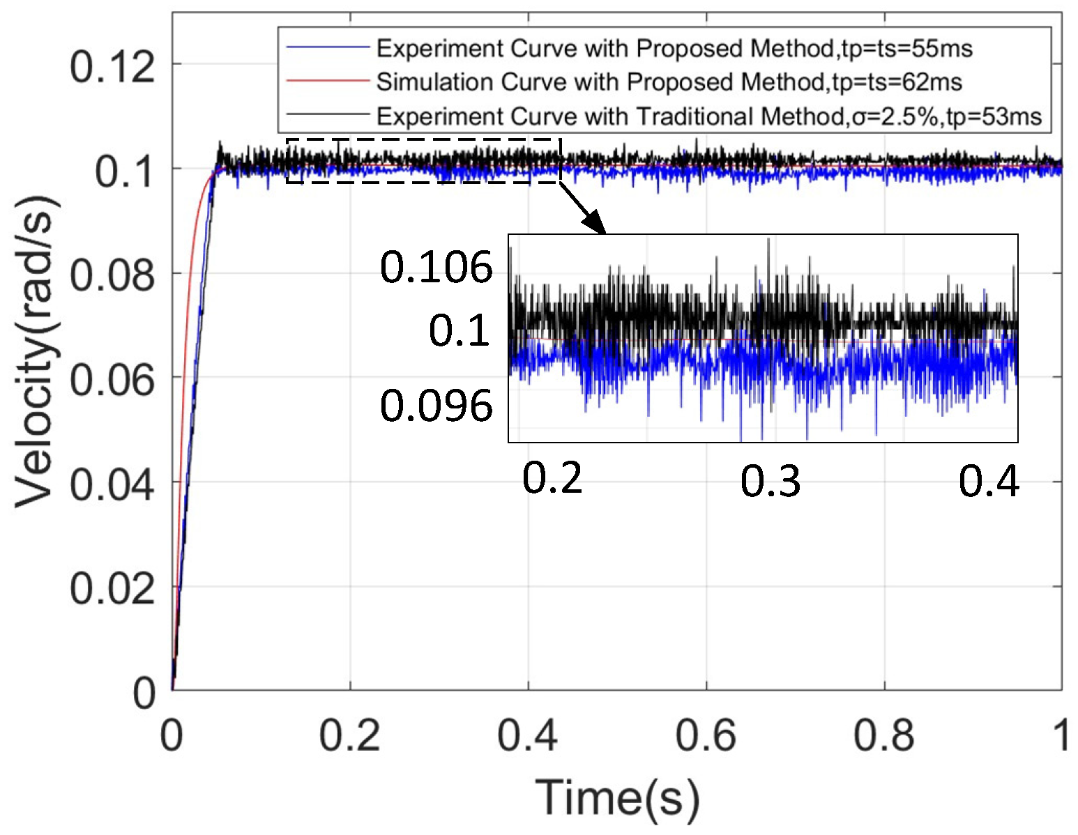
Figure 10 presents the experimentally measured step response curves of the velocity loop. The proposed PI design method produces a speed response curve with a target of 0.1 rad/s, achieving a response time of 55 ms without overshoot and maintaining a relatively small error. In comparison, the simulated speed response curve demonstrates a response time of 62 ms. The maximum steady-state speed tracking errors for the experimental and simulated curves are rad/s and rad/s, respectively, confirming that the designed speed PI controller delivers satisfactory control performance. Conversely, the PID control curve obtained via the traditional design method shows a 2% steady-state deviation in rotational speed, necessitating an extended period for adjustment and error elimination.
Figure 10.
The velocity curve obtained by the proposed PI controller design method based on the dual-lag link system.
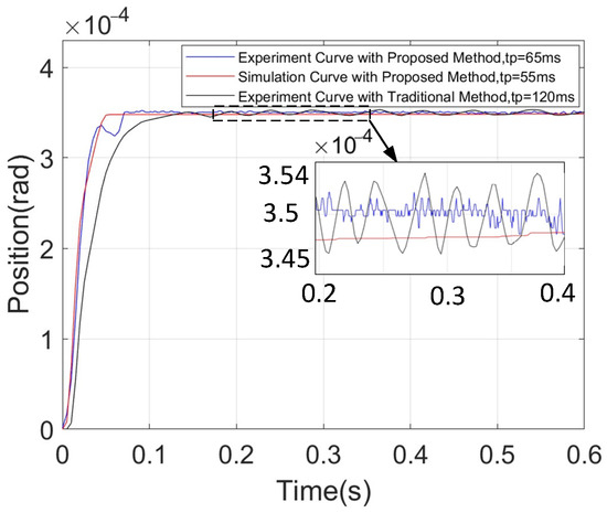
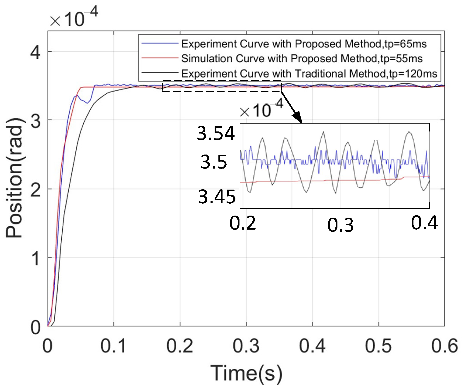
Figure 11 presents the experimentally obtained step response curves of the position control loop. The proposed proportional integral (PI) controller design method produces a position response with a resolution of 350 μrad. Experimentally, the system achieves a response time of 65 ms without overshoot, exhibiting a maximum position tracking error of 0.33 rad. In contrast, the simulation results indicate a faster response time of 55 ms but with a larger steady-state error of 1.45 rad. When compared to the experimental performance of a PI controller designed using conventional methods, the proposed approach demonstrates superior performance, as the traditional controller exhibits a jitter amplitude of 6 μrad and a response time of 120 ms, both of which are significantly less favorable than those obtained with the proposed design methodology.
Figure 11.
The position curve obtained by the proposed PI controller design method based on the dual-lag link system.
In summary, the PI controller design approach presented in this study demonstrates superior control performance. The experimental findings closely align with theoretical design predictions, indicating the method’s applicability to systems exhibiting similar characteristics.
5. Conclusions
This study presents a comprehensive methodology for designing universal proportional integral (PI) controllers tailored to Permanent Magnet Synchronous Motor (PMSM) servo systems. The proposed design framework concurrently addresses the incorporation of filters aimed at mitigating feedback loop noise and the fulfillment of system bandwidth specifications, thereby offering a more intuitive and integrated design strategy. Validation through both simulation and experimental investigations demonstrates strong agreement, confirming the efficacy of the approach. Notably, compared to conventional design techniques, the current loop exhibits a significant enhancement in response performance, with the 1 A current step response time reduced from 42 ms to 6 ms without overshoot. In the speed control loop, the steady-state error at a 0.1 rad/s speed step is diminished substantially, achieving a 21.4% improvement in control accuracy while preserving the original response time. Furthermore, the position loop shows a reduction in control error from 6 μrad to 3 μrad, alongside a decrease in response time from 120 ms to 65 ms, with a minimal static control error of 0.33 μrad.
Despite these advancements, the current methodology is constrained by its reliance on numerical computation techniques to establish the relationship between controller parameters and system performance metrics. In summary, the proposed design framework offers a novel and effective alternative for the selection and tuning of PI controllers in servo motor applications.
Author Contributions
Conceptualization, L.K. and J.W.; methodology, L.K. and J.W.; software, L.K., H.H. and X.D.; validation, L.K., H.H., X.D. and B.L.; formal analysis, H.H.; investigation, L.K.; resources, L.K.; data curation, H.H.; writing—original draft preparation, L.K., H.H. and X.D.; writing—review and editing, L.K.; funding acquisition, L.K. All authors have read and agreed to the published version of the manuscript.
Funding
This research was funded by Jilin Province’s Special Project for Concentrated Efforts and Breakthroughs: “Intelligent Lightweight Ultra-Wide Swath High-Resolution Remote Sensing Satellite and Data Processing Technology”, No. 2025JLGJ0013GX.
Institutional Review Board Statement
Not applicable.
Informed Consent Statement
Not applicable.
Data Availability Statement
Dataset available on request from the authors.
Conflicts of Interest
Authors Lingbo Kong, Huiying Hu, Xinyu Dong and Boting Liu were employed by the Chang Guang Satellite Technology Company. The remaining authors declare that the research was conducted in the absence of any commercial or financial relationships that could be construed as a potential conflict of interest.
References
- Ismail, K.; Rachmildha, T.D.; Rijanto, E.; Haroen, Y.; Ristiana, R. Comparison of PID Controller Tuning Methods for Multi PMSM Angular Speed Synchronization. In Proceedings of the International Conference on Electric Vehicular Technology (ICEVT), Surakarta, Indonesia, 30–31 October 2018; pp. 95–99. [Google Scholar]
- Saxena, M.; Ghosh, M.; Kulshrestha, D.; Paliwal, N.; Pandit, M. Optimized PI/PD/PID Controller Design for DC Motor Speed Control: A Comparative Study of Random Forest-Based Tuning & Classical Methods. In Proceedings of the 2025 Devices for Integrated Circuit (DevIC), Kalyani, India, 5–6 April 2025; pp. 396–400. [Google Scholar]
- Xin, C.; Zhang, W.; Yang, Q. Research and Application Prospect of PID Auto-tuning. In Proceedings of the Chinese Control Conference (CCC), Shenyang, China, 27–29 July 2020; pp. 5991–5995. [Google Scholar]
- Singh, S.; Singh, V.; Rani, A.; Yadav, J. Optimization of PID controller based on various tuning methods. In Proceedings of the International Conference on Power, Instrumentation, Energy and Control (PIECON), Aligarh, India, 10–12 February 2023; pp. 1–6. [Google Scholar]
- Wu, Q.; Chen, A.; Cao, Y. Optimal PID Parameter Tuning Method of First-Order Time-Lag System Based on BP Neural Network. In Proceedings of the International Conference on Power, Intelligent Computing and Systems (ICPICS), Shenyang, China, 26–28 July 2024; pp. 1001–1006. [Google Scholar]
- Pandey, S.K.; Veeranna, K.; Kumar, B.; Deshmukh, K.U. A Robust Auto-tuning Scheme for PID Controllers. In Proceedings of the Annual Conference of the IEEE Industrial Electronics Society, Singapore, 18–21 October 2020; pp. 47–52. [Google Scholar]
- Lee, Y.; Lee, M.; Park, S.; Brosilow, C. PID Controller Tuning for Processes with Time Delay. In Proceedings of the 11th KACC, Pohang, Republic of Korea, 24–26 October 1996; pp. 291–294. [Google Scholar]
- Lee, Y.; Park, S.; Lee, M. PID Controller Tuning to Obtain Desired Closed Loop Responses for Cascade Control Systems. Ind. Eng. Chem. Res. 1998, 37, 1859–1865. [Google Scholar] [CrossRef] [Scilit]
- Khubalkar, S.W.; Chopade, A.S.; Junghare, A.S.; Aware, M.V. Design and tuning of fractional order PID controller for speed control of permanent magnet brushless DC motor. In Proceedings of the International Conference on Control, Measurement and Instrumentation (CMI), Kolkata, India, 8–10 January 2016; pp. 326–330. [Google Scholar]
- Jin, Y.; Du, M.; Han, J.; Liu, D. Research on Self-tuning Fractional Order PID Speed Control of Permanent Magnet Synchronous Motor Based on Torque Observer Compensation. In Proceedings of the International Conference on Smart Grid and Clean Energy Technologies (ICSGCE), Jilin, China, 18–20 October 2024; pp. 8–13. [Google Scholar]
- Qi, Z.; Yang, H.; Li, M.; Li, J. Research on Fractional Order PID Controller in Servo Control System. Conference on Energy. In Proceedings of the Internet and Energy System Integration (EI2), Changsha, China, 8–10 November 2019; pp. 2931–2935. [Google Scholar]
- Yao, W. The Parameter Tuning Method of the Fuzzy PID Control Based on an Improved Differential Evolution Algorithm. In Proceedings of the Asia-Pacific Conference on Communications Technology and Computer Science (ACCTCS), Shenyang, China, 23–25 April 2025; pp. 820–826. [Google Scholar]
- Fu, J.; Lu, X.; Yang, G. PID Control Parameter Tuning Method of Permanent Magnet Synchronous Motor Based on Improved AHP-BP Neural Network Algorithm. In Proceedings of the International Conference on Civil Aviation Safety and Information Technology (ICCASIT), Hangzhou, China, 23–24 October 2024; pp. 1255–1262. [Google Scholar]
- Tang, X.; Jia, C.; He, Z. CLPSO: An Improved PSO Algorithm and its Application to PID Parameter Tuning. In Proceedings of the International Conference on Electronic Information Engineering and Computer (EIECT), Shenzhen, China, 27–29 September 2024; pp. 820–824. [Google Scholar]
- Deshmukh, J.K.; Tirole, R.; Bhaskar, A. Optimization of PID Controllers for Cascade Control Loops Using Particle Swarm Optimization Techniques. In Proceedings of the International Conference on I-SMAC (IoT in Social, Mobile, Analytics and Cloud) (I-SMAC), Kirtipur, Nepal, 3–5 October 2024; pp. 473–478. [Google Scholar]
- Ivanova, D.; Krasteva, A.; Ruseva, V. Tuning PID Controllers Parameters of the DC Motor with Genetic Algorithm. In Proceedings of the Conference on Electrical Machines, Drives and Power Systems (ELMA), Sofia, Bulgaria, 19–21 June 2025; pp. 1–5. [Google Scholar]
- Trujillo, K.B.; Álvarez, J.G.; Cortés, E. PI and PID Controller Tuning with Deep Reinforcement Learning. In Proceedings of the IEEE International Conference on Automation/XXV Congress of the Chilean Association of Automatic Control (ICA-ACCA), Curicó, Chile, 24–28 October 2022; pp. 1–6. [Google Scholar]
- Gao, X.; Huang, C.; Lan, W.I. Optimal PID Tuning for Plants with Random Parameters. In Proceedings of the China Automation Congress (CAC), Chongqing, China, 17–19 November 2023; pp. 1611–1616. [Google Scholar]

Disclaimer/Publisher’s Note: The statements, opinions and data contained in all publications are solely those of the individual author(s) and contributor(s) and not of MDPI and/or the editor(s). MDPI and/or the editor(s) disclaim responsibility for any injury to people or property resulting from any ideas, methods, instructions or products referred to in the content. |
© 2026 by the authors. Licensee MDPI, Basel, Switzerland. This article is an open access article distributed under the terms and conditions of the Creative Commons Attribution (CC BY) license.