


Abstract
The escalating incidence of knee cartilage damage underscores the need for improved treatment approaches, while the present modalities are constrained by limitations. This paper presents a novel mobile device for manipulating microrobots to deliver therapeutic agents to damaged knee cartilage areas using external magnetic fields. A curved telescopic mechanism, proposed for the first time, enables effective navigation along complex human body contours, thereby overcoming the limitations of conventional linear approaches. The device is equipped with a precise closed-loop controller. A model-based optimization of magnetic end-effector position and orientation is developed to ensure high targeting efficiency and repeatability. The system performances are verified in a human-sized phantom model, demonstrating the superior targeting accuracy, and achieving outcomes exceeding those of conventional systems. These findings underscore the system’s strong potential for clinical translation in regenerative knee therapies, offering a portable, low-cost, and effective alternative to existing methods.
1. Introduction
The global prevalence of knee cartilage damage is steadily rising, largely due to age-related degeneration, obesity, and traumatic injuries associated with sports or accidents [1]. Knee cartilage plays a vital role in joint mobility and load-bearing; however, its avascular and aneural nature significantly limits its intrinsic healing capacity [2]. Prolonged cartilage degeneration frequently progresses to knee osteoarthritis (KOA), a debilitating condition affecting over half a billion elderly individuals worldwide [3].
Treatment strategies for knee cartilage damage generally fall into three categories: chondroprotection, chondro-reparation, and chondro-regeneration, selected based on lesion severity and patient profile [4]. Chondroprotection relies on conservative measures such as oral medications or intra-articular injections to relieve symptoms, but its long-term clinical effectiveness remains inconclusive [5]. Chondro-reparation approaches, including abrasion, drilling, and microfracture, stimulate mesenchymal cell recruitment through induced bleeding. While cost-effective and relatively simple, these methods are mainly suitable for younger patients (<50 years) and carry risks of recurrence [6]. Chondro-regeneration, which employs autografts, allografts, or osteochondral tissue transplantation, aims to restore cartilage more effectively but is limited by high cost and suboptimal long-term outcomes [7].
In recent years, mesenchymal stem cells (MSCs) have emerged as a promising therapeutic option for cartilage regeneration owing to their multilineage differentiation potential [8,9]. Clinical studies have demonstrated significant improvements in knee pain and function following intra-articular MSC injections [8,9,10]. However, critical challenges remain. Current delivery methods exhibit poor targeting efficiency (<1%) because injected cells disperse within the joint cavity, where fluid vortices flush them away from the defect site [11,12,13]. Moreover, the limited half-life of MSCs within the joint space underscores the need for sustained, localized delivery. These limitations highlight the urgent requirement for an active guidance system to accurately deliver and retain therapeutic agents at the defect site.
Microrobot-based navigation has been widely investigated for targeted therapy, employing actuation mechanisms such as acoustic, optical, chemical, or magnetic forces [10]. Among these, magnetic actuation is particularly attractive for clinical application due to its deep penetration, biocompatibility, and high force output [11,12]. Prior studies have explored magnetic microrobots for MSC delivery, including microrobots loaded with adipose-derived MSCs for cartilage regeneration in animal models [13]. While effective in concept, these systems rely heavily on manual magnetic manipulation, which introduces operator-dependent variability and targeting errors exceeding 20%. Furthermore, conventional magnetic manipulation systems (MMS) require large coil arrays and substantial power consumption, making them costly, bulky, and impractical for routine clinical use [14,15,16,17,18]. These limitations underscore the need for a portable, low-power, and user-friendly device that can seamlessly integrate with existing surgical environments.
The first portable curved telescopic device (PCTD) for magnetic guidance of MSC-loaded microcarriers (MCs) to damaged cartilage regions was introduced in our previous work to address these challenges [19]. The proposed system integrates a novel curved telescopic mechanism with two motorized degrees of freedom (DoF), ensuring sufficient workspace coverage while maintaining a compact design. At its distal end, a magnetic actuator is embedded for controlling magnetic MCs. Unlike bulky coil-based MMS, the PCTD consumes minimal power and features an all-on-board configuration that facilitates integration with surgical beds and intraoperative workflows. Although the targeting experiments were performed, the minimum targeting efficiency (TE) in the successful cases was 88% for two different target areas using manually selected poses of the magnetic end-effector (EEF). There is no guarantee that this performance can be maintained in clinical scenarios, where the navigation protocol is required to ensure high TE for different patients and treatment areas. To cope with this challenge, in this work, we present a model-based optimization of EEF position and orientation for precise navigation of MCs from a selected injection point to targeted areas. In this framework, the basic dynamic responses of MCs were modified from [20].
Building upon this foundation, we present the optimization and experimental validation of the PCTD. Motion characterization and phantom targeting experiments demonstrate that the system achieves high targeting accuracy, repeatability, and efficiency, surpassing the performance of conventional stationary systems. This work highlights a transformative step toward affordable, clinically adaptable robotic assistance in knee cartilage regeneration, bridging the gap between stem cell therapy and practical, effective delivery.
2. Methodology
2.1. Portable Curved Telescopic Device
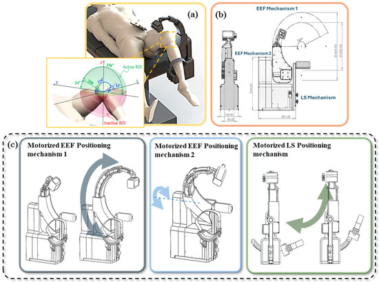
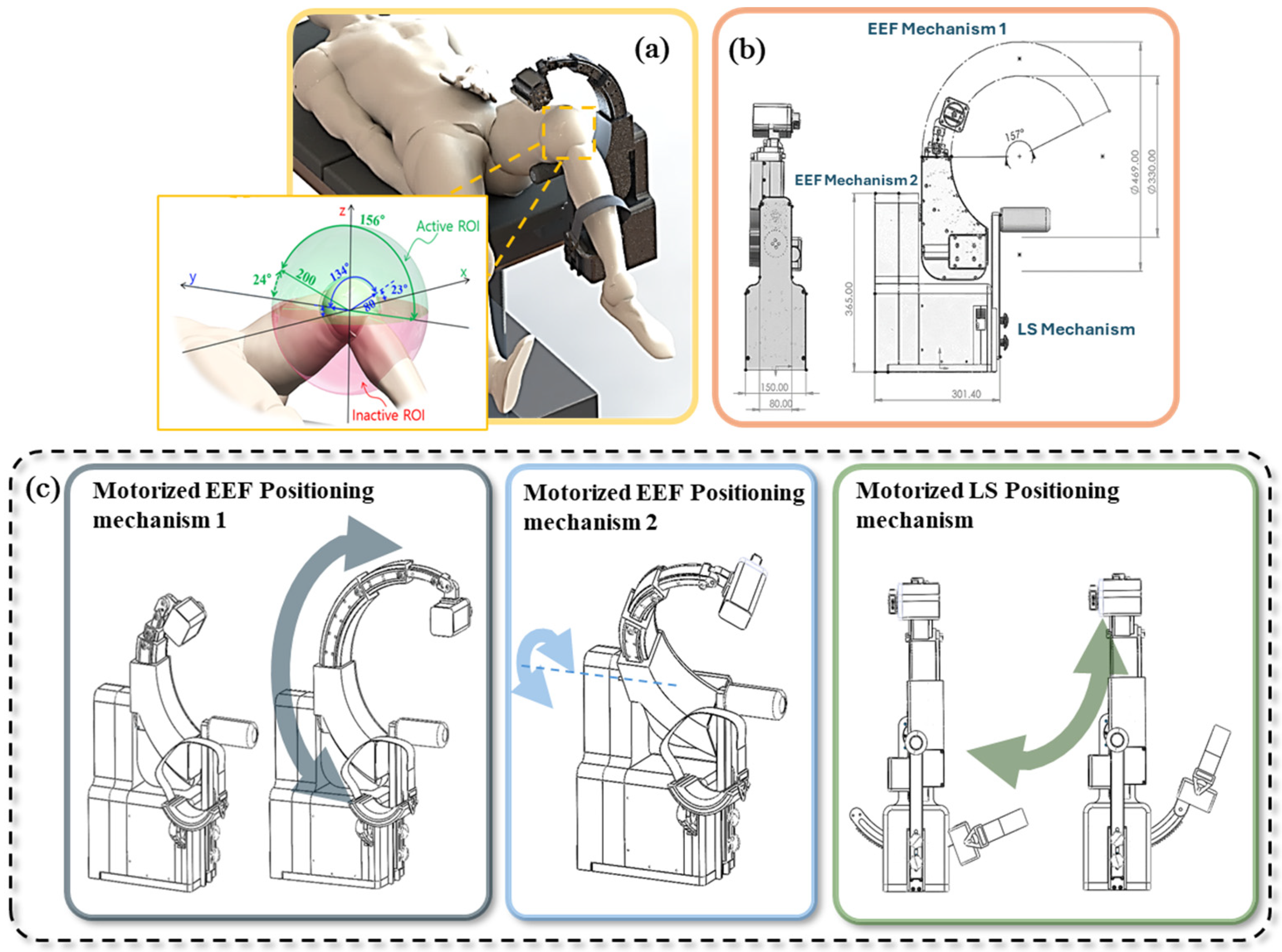
In conventional therapeutic approaches for knee cartilage repair, 6-DoF robotic systems are typically employed to perform precise manipulations during total knee arthroplasty and related procedures. While these systems provide high positioning accuracy and motion flexibility, their large size, high cost, and limited compatibility with other surgical instruments hinder their use in compact or integrated clinical environments. To overcome these limitations, a PCTD was developed not only to address the shortcomings of conventional robotic systems but also to specifically enable magnetic guidance of MSC-loaded MCs toward damaged cartilage regions. The device was carefully designed to operate efficiently within the effective workspace defined by the anatomical constraints of the human knee (maximum diameter was selected as Ø160 mm), thereby preventing collision with the joint surface and ensuring procedural safety. Furthermore, its compact and modular design facilitates seamless integration with intraoperative instruments such as the arthroscope, allowing precise magnetic actuation, improved targeting efficiency, and enhanced clinical applicability. The real-world scenario of applying PCTD in knee surgery can be illustrated as shown as Figure 1a.
Figure 1.
Overview of the proposed PCTD system: (a) real-world surgical setup; (b) hardware structure and specifications; and (c) motorized actuation mechanisms of the EEF and LS.
By exploiting the anatomical constraint that the EEF always points toward the center of the hemispherical workspace, the required degrees of freedom are significantly reduced. Instead of employing a full 6-DoF configuration, the proposed PCTD achieves magnetic actuation with a simpler yet effective 3-DoF mechanism: two rotational motions about the x- and y-axes and one radial translational motion toward or away from the knee center. Figure 1b presents the overall configuration of the three main subsystems: the curved telescopic mechanism (EEF Mechanism 1), the body rotary joint (EEF Mechanism 2), and the leg support mechanism (LS Mechanism), together with the key technical specifications of the proposed system. The EEF Mechanism 1, which rotates about the y-axis to extend and retract the EEF along a curved trajectory, operates in coordination with EEF Mechanism 2, which rotates about the x-axis to provide lateral coverage of the damaged cartilage region. This coordinated motion enables the system to realize a hemispherical workspace. Additionally, the LS Mechanism provides radial translation to adjust the EEF–knee distance, allowing fine modulation of the magnetic field strength and the resulting forces exerted on the MSC-loaded MCs. These mechanisms are schematically illustrated in Figure 1c, arranged from left to right.
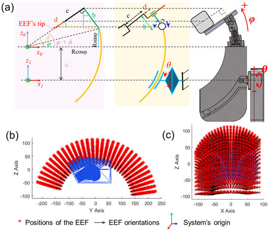
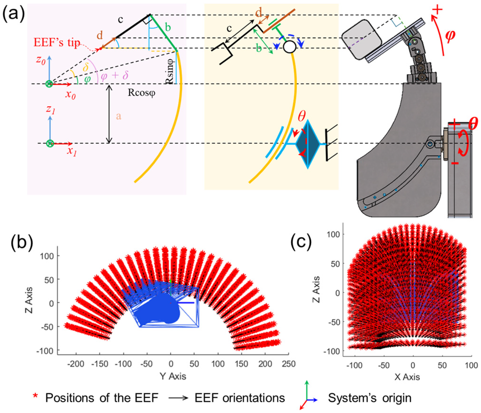
To ensure that the proposed curved telescopic mechanism operates effectively within the hemispherical workspace, the kinematics of the PCTD were analyzed to visualize its reachable region and demonstrate the system’s capability for magnetic guidance of MSC-loaded MCs. Figure 2a presents the simplified geometry and the corresponding kinematic diagram of the curved telescopic mechanism. The system consists of four main variables, including two motorized joints—the EEF Mechanism 1 (denoted as φ) and EEF Mechanism 2 (expressed as θ)—and two manually adjustable joints—the hinge joint (represented by δ) and the linear joint (indicated by d). Based on the kinematic diagram, the initial position of the EEF of the curved telescopic mechanism can be expressed as:
where R, b, c are the radius of the EEF Mechanism 1, the distance from the center of hinge joint to the tool tip, and the length measured between the linear joint to the tip of EEF, respectively.
Figure 2.
Kinematic analysis of the proposed PCTD: (a) simplified geometric model of the curved telescopic mechanism (left) and its corresponding kinematic diagram (right); the reachable workspace of the device in (b) Y−Z plane; (c) X−Z plane.
Because Mechanism 1 and Mechanism 2 rotate about different axes, a local coordinate frame {1} is assigned to the rotation axis of EEF Mechanism 2. The EEF coordinate at an arbitrary input angle θ can therefore be expressed with respect to frame {1} as follows:
where a is the distance between the EEF Mechanism 1 and EEF Mechanism 2.
The global EEF position with respect to the base coordinate is then obtained as follows:
As illustrated in Figure 2b,c, the workspace of the portable knee treatment device is presented in the Y-Z and X-Z side views. It can be clearly observed that the workspace of the proposed device fully covers the knee phantom, demonstrating its suitability for intraoperative applications in the knee joint region. Details of the system parameters used in this plot are summarized in Table 1.
Table 1.
Parameters used in system kinematics.
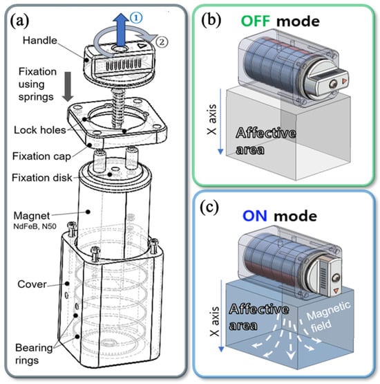
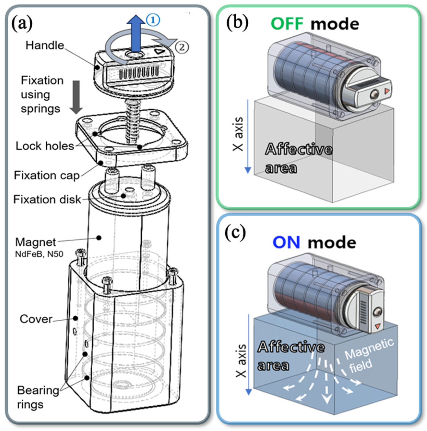
Moreover, the EEF of the proposed PCTD integrates a cylindrical permanent magnet, which is of N50 grade and has a magnetization direction perpendicular to its body axis to enable ON/OFF the magnetic field, and serves as the magnetic actuator for generating the external magnetic field required to guide the MSC-loaded MCs. The mechanically switchable configuration of the magnetic EEF is shown in Figure 3a, where a two-step action of switching between the ON/OFF mode including pulling and turning the handle is illustrated. The working mechanism of the OFF and ON modes has been illustrated in Figure 3b and Figure 3c, respectively. The cylindrical magnet has a fixed internal magnetization direction, and the operator changes the output state by mechanically rotating the magnet via the handle. When the dipole is aligned toward the region of interest (ROI), the system enters the ON mode, whereas rotating the dipole away from the ROI produces the OFF mode. This dipole-reorientation mechanism generates two distinct magnetic output states [19].
Figure 3.
The magnetic EEF: (a) Details of switchable configuration; (b) OFF mode working mechanism; (c) ON mode working mechanism.
2.2. Model-Based Optimization of the End Effector for Magnetic Particle Targeting
In this section, a physics-based dynamic model of the magnetic particle in a fluid medium is developed to accurately characterize its motion under the influence of multiple physical effects. The aim is to provide a rigorous formulation that captures the interplay of forces acting on the magnetic particle, thereby providing a formulation that allows us to simulate particle trajectories with higher fidelity and to systematically optimize the EEF orientation and position for magnetic targeting applications.
The formulation begins with Newton’s second law of motion, in which the net force acting on the magnetic particle is expressed as the sum of three major components, the magnetic force generated by the magnetic EEF, the fluidic drag due to relative motion between the particle and the surrounding fluid, and the gravitational force acting on the particle. The governing equation presented below is based on the dynamic equation of the magnetic particle in [20]:
where m, qp, Fmag, Fdrag,, Fgravity are the particle mass, the 3D position of the particle, the magnetic force, the fluidic drag force, and the gravitational forces, respectively.
The magnetic force acting on the magnetic particle can be expressed as follows:
where V, M, B are the magnetic particle volume, magnetic moment vector, and the magnetic field, respectively.
The fluidic drag force exerted on the spherical carrier can be defined as:
where dp denotes the diameter of the spherical magnetic particle. µfluid represents the dynamic fluid viscosity of the fluid surrounding the magnetic particle. While νfluid denotes the flow velocity vector at the magnetic particle position which is interpolated from finite element simulation of unit-amplitude injection flow.
The gravitational forces acted on the particles can be expressed as follows:
where , denote the mass density of MC and fluidic environment.
By analyzing the three contributing forces in (4), combined with their equations from (5) to (7), the governing dynamic equation can be presented as:
Let us set , and substitute them into (8) as:
Applying the Laplace transform to (9) with zero initial condition , it is represented as:
By applying the inverse Laplace, the particle position and its traveling velocity at t can be obtained as:
The analytical form of (11) enables direct computation of the particle’s displacement over time. This compact model serves as the computational core of the model-based EEF optimization, allowing accurate prediction of its trajectory from the injection point to the target region.
Subsequently, these derived analytical solutions are implemented into the simulation to perform the model-based optimization. The dynamic model of the magnetic particle is then integrated with the kinematic structure of the PCTD to enable a complete physical-to-geometrical mapping.
The optimization objective is to identify the EEF pose that minimizes the distance between the predicted end position of the magnetic particle and the desired target inside the knee phantom. The cost function is defined as follows:
where Pt is the target position, qend is the predicted end-point of the particle.
For any given combination of angular variables (θ, φ, δ), the spatial pose of the EEF tip is computed through the kinematic model. This pose determines the orientation of the permanent magnet attached to the EEF, from which the direction and magnitude of the magnetic field acting on the particle are calculated using the point-dipole formulation. Once the magnetic field is established, the dynamic model simulates the particle’s motion by numerically integrating the forces acting on it. The simulation proceeds until the traveled distance from the injection point equals the anatomical distance to the target. After all configurations are evaluated, the combination yielding the smallest targeting error is selected as the optimal EEF pose (θ*,φ*,δ*).
Once the optimal pose is obtained, it is transferred to the physical system, where the EEF is commanded to move toward the optimized configuration using the kinematic model combined with a closed-loop PID controller. This control scheme ensures precise positioning of the EEF at the optimized location, thereby generating the required magnetic field distribution to guide the MSC-loaded MCs effectively toward the target region.
3. Experimental Results
3.1. Position Control
To apply the proposed model-based optimization algorithm efficiently, the EEF control accuracy of the two control joints needs to be ensured. Hence, two different experiments were carried out, including open-loop control and closed-loop control. In both experiments, an inclinometer (MSENS-IN-D-485, DAS Co. Ltd., Hwaseong, South Korea) was attached to the last joint of EEF Mechanism 1, and its feedback values were used as the ground truth to evaluate the control accuracy.
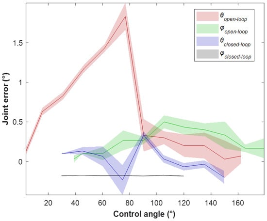
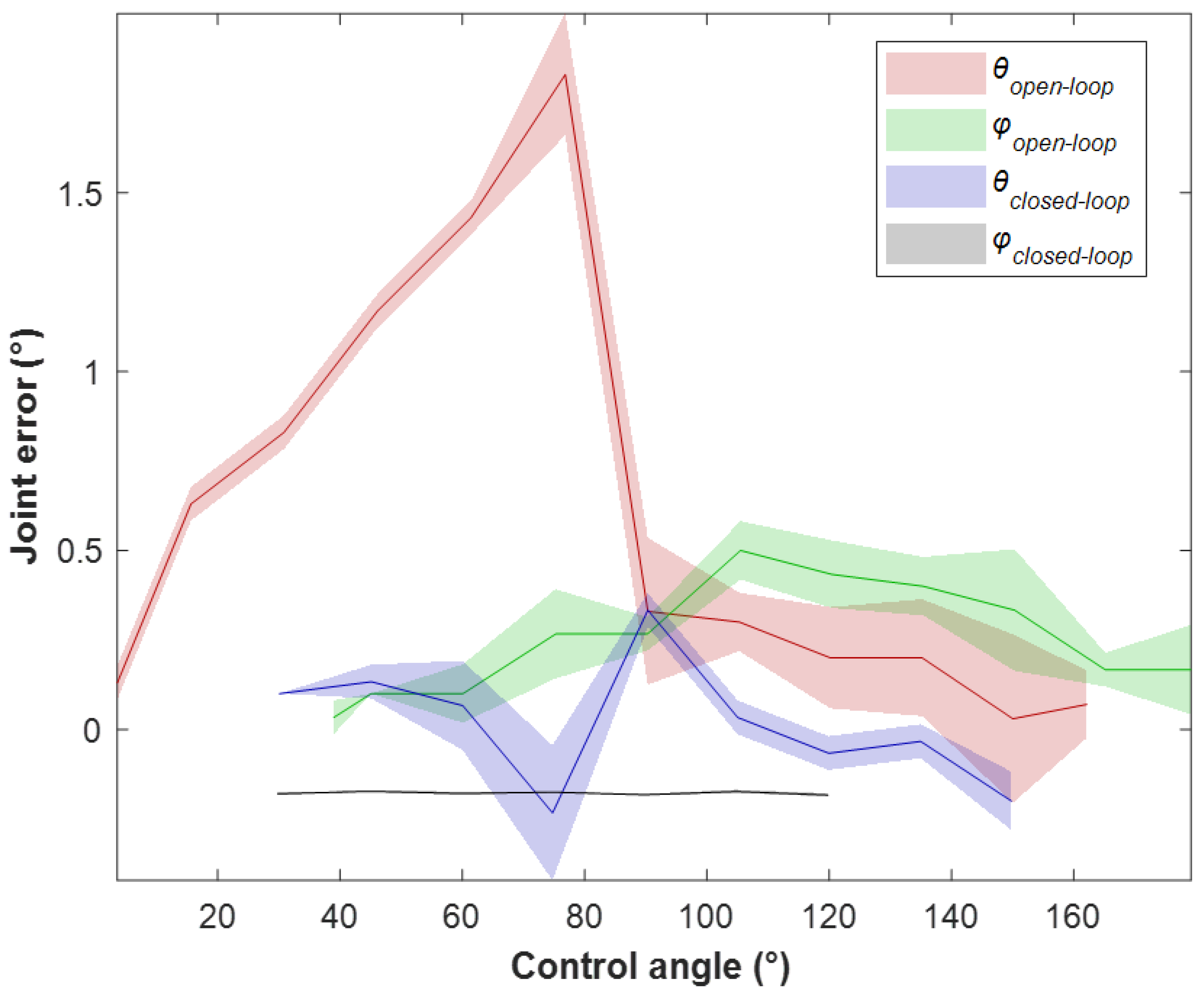
Initially, the open-loop control experiment was carried out. The EEF Mechanism 1 joint was sequentially controlled to predetermined angles within the workspace. The measurements obtained from the inclinometer were used as reference values, while those from the encoder were used for evaluation. A similar procedure was applied to the EEF Mechanism 2 joint, with each measurement repeated three times to ensure reliability. Figure 4 illustrates the error results of the two system joints. In this figure, the bold solid lines indicate the mean values measured at each predefined angle, whereas the shaded bounds represent the standard deviations. For the EEF Mechanism 1 joint, shown in green, the maximum angular error was approximately 0.5°. When expressed in terms of root mean square error (RMSE), the corresponding positional errors were 0.3 mm, 0 mm, and 0.3 mm along the x-, y-, and z-axes, respectively. Meanwhile, the error at the EEF Mechanism 2 joint, shown by the red curve, was considerable. In the range between 60° and 90°, the maximum angular error reached approximately 2°. The corresponding positional errors, expressed as RMSE, were 0 mm, 1.3 mm, and 2.0 mm along the x-, y-, and z-axes.
Figure 4.
Verification of the PCTD’s EEF control accuracy: Control performance of EEF mechanisms 1 and 2 under open-loop and closed-loop control at different angles.
Under closed-loop control, the PID algorithm was implemented, using the inclinometer’s angular signal as real-time feedback for both joints. Because the PCTD was operated at a slow and safe speed to allow the user sufficient time to respond to any unintended joint motion, only the proportional term of the PID controller was required. The gain was tuned empirically to achieve the desired accuracy for both EEF Mechanism 1 and EEF Mechanism 2 joints without causing excessive overshoot. This scheme greatly reduced the errors, as shown by the black and purple curves in Figure 4. The quantitative results are summarized in Table 2, where the PID controller was evaluated using percentage overshoot (PO), rise time per degree (tr/degree), settling time per degree (ts/degree), and the maximum angular error. In addition, the RMSE was first calculated separately for the φ and θ joint cases to assess their individual contribution. The overall positional RMSE was then calculated directly from all experimental samples. With the PID scheme applied, the maximum angular deviation of both joints decreased to 0.2°, and the overall EEF positional RMSE were 0.14, 0.17, and 0.33 mm along the x-, y-, and z-axes, respectively.
Table 2.
Joint response metrics under PID control.
These outcomes demonstrate that the PID controller enables stable convergence, accurate response, and reliable consistently achievement of the optimized EEF poses, making it suitable and effective control strategy for the proposed system.
3.2. Optimization Results
The simulation was performed to analyze the magnetic targeting performance of the optimized PCTD’s EEF within the reconstructed 3D knee phantom via MATLAB 2024b software. The particle trajectory was computed for various combinations of the EEF’s angular parameters (θ, φ, δ) following the derived dynamic model. For each configuration, the system simulated the particle motion under magnetic, drag, and gravitational forces until the particle reached the vicinity of the target region. The key simulation parameters were defined as follows: the injection flow rate was set to 5 mL/min using a 16G catheter with an inner diameter of 1.7 mm, resulting in a flow velocity at the catheter tip of approximately 35 mm/s. The particle’s diameter, density, and magnetization were 450 µm, 1.09 ± 0.01 g/mL, and 20 emu/g, respectively. The fluid dynamic viscosity was 1 mPa·s.
A full parametric sweep of θ = 7–156°, φ = 17–140°, δ = −30–30° was carried out to evaluate all feasible configurations, with a total runtime of approximately 17 h. The resulting database recorded the particle position and corresponding targeting error.
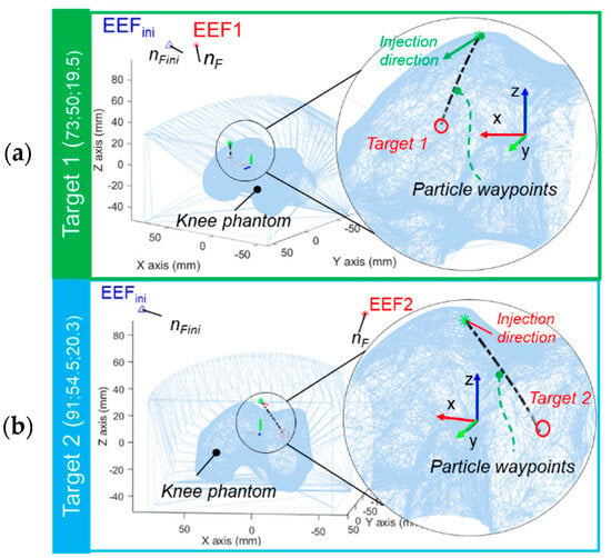
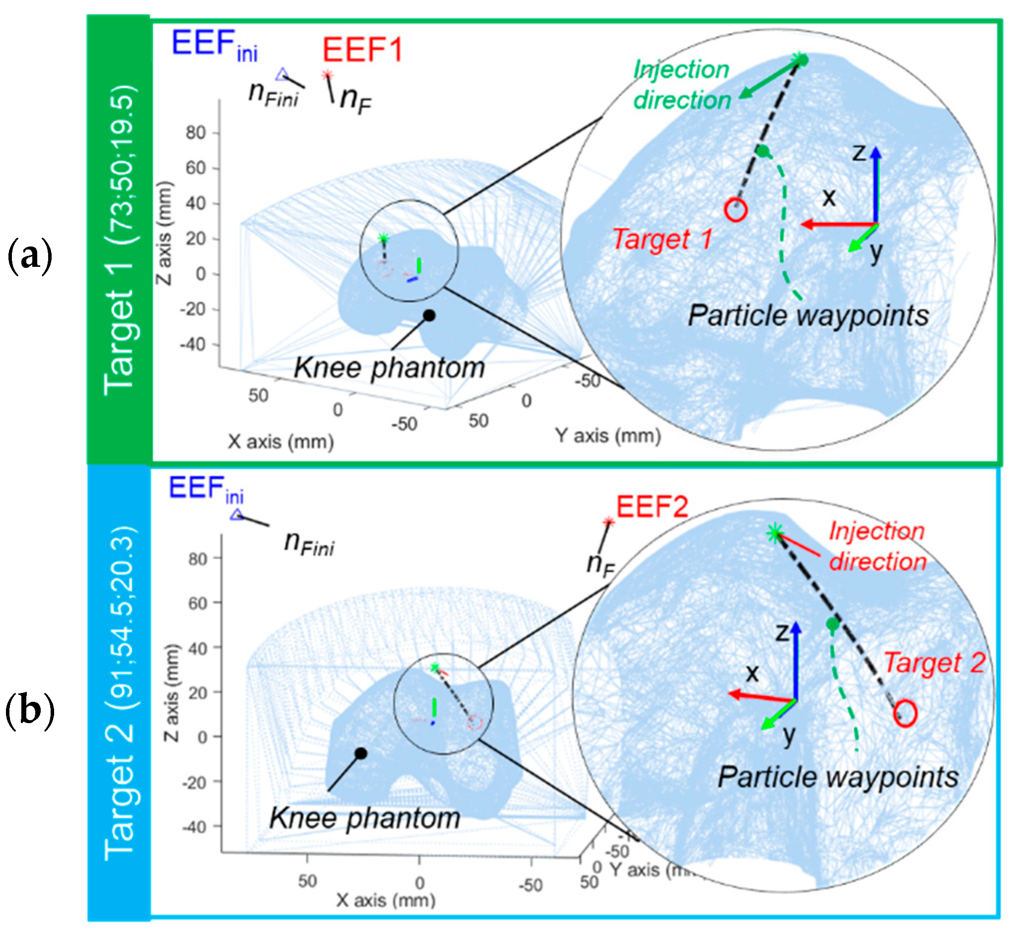
The optimization was applied to two different targeted areas. The optimization identified an optimal EEF orientation of θ* = 115°, φ* = 17°, and δ*= 22° with the end-point error is 0.072 mm for target 1, located at x = 73 mm, y = 50 mm, z = 19.5 mm. For target 2, located at x = 91 mm, y = 54.5 mm, z = 20.3 mm, the optimal orientation was obtained at of θ* = 137°, φ* = 96°, and δ* = 22° with the end-point error is 0.038 mm. As illustrated in Figure 5, the optimized trajectories converged significantly closer to both targets, demonstrating the effectiveness of the proposed model-based optimization in guiding magnetic particles toward different target positions.
Figure 5.
Simulation−based optimization results: (a) Optimal EEF position for Target 1; (b) Optimal EEF position for Target 2.
3.3. Targeting Results
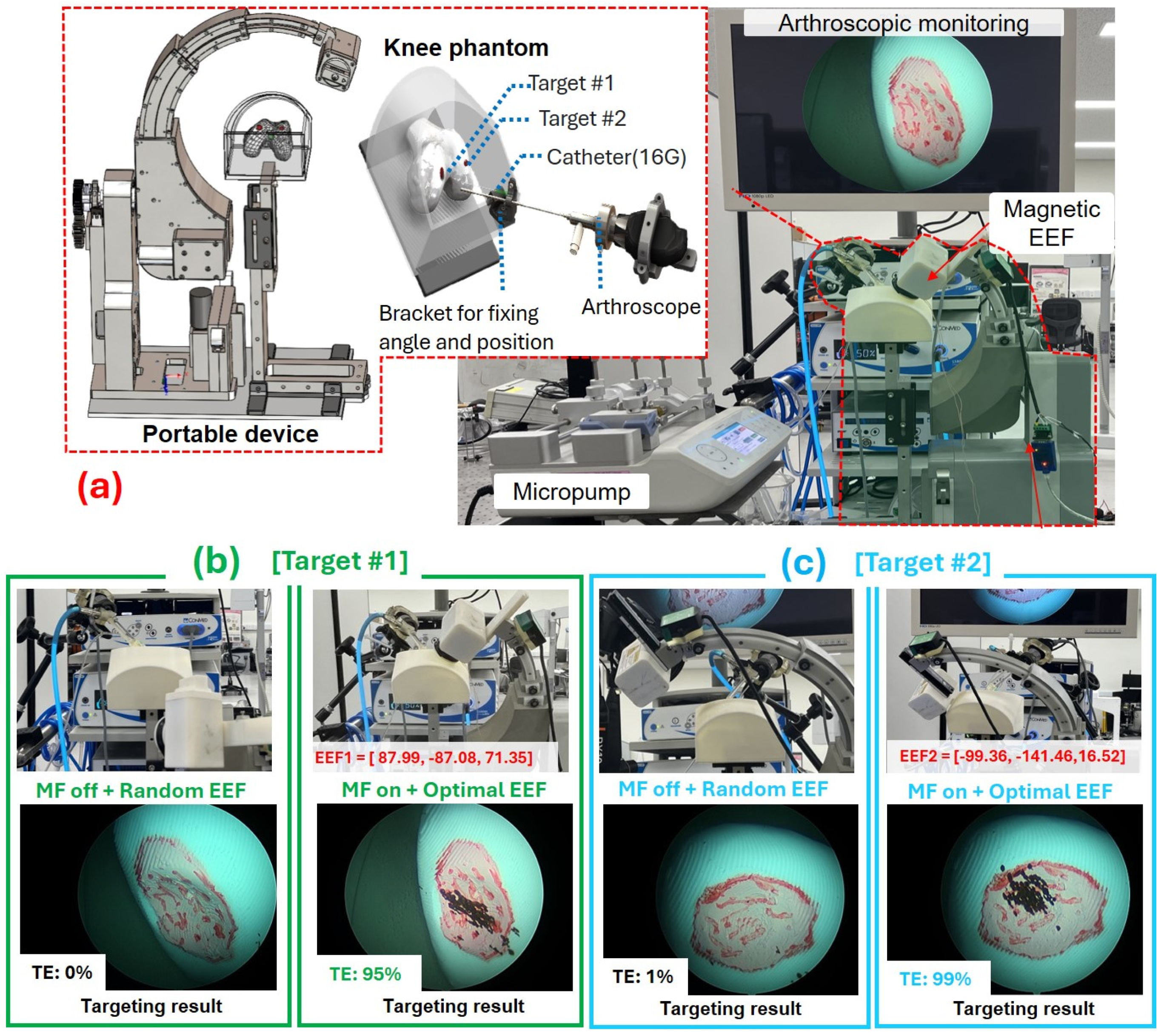
To experimentally validate the effectiveness of the proposed model-based optimization, two magnetic targeting trials were conducted inside the 3D knee phantom using the optimal EEF configurations derived from simulation. The phantom model was reconstructed from a CT-scanned human knee and scaled to the maximum anatomical size, with an outer diameter of approximately 150 mm according to SizeKorea data. For visualization, an arthroscopic system (IM8120 Eyecup camera head, ConMed, Largo, FL, USA) was coupled with an autoclavable arthroscope (Ø2.9 mm, 30°, 152 mm, Linvatec, Frankfurt, Germany) and connected to a camera control unit (IM8000, ConMed, USA). The injection system consisted of a 16G LV catheter (Shinchang Medical Co. Ltd., Gumi-si, Republic of Korea) connected to a 30 mL syringe (Shinchang Medical Co., Ltd.) filled with deionized water and mounted on a programmable micropump (Fusion 4000, Chemyx Inc., USA) to precisely control the injection speed. The magnetic carriers were preloaded into the injection channel using a 5 mL syringe (Shinchang Medical Co., Ltd.). The MCs used in this experiment were MagLus BMG-S2 microcarriers (Biot Inc., Gwangju, Republic of Korea) [13] with an average particle diameter of 450 ± 50 µm and a magnetization of around 20 emu/g.
Based on the optimization framework, the EEF’s orientation and position corresponding to the minimum targeting error were first determined through simulation. These optimal angular parameters were then transferred to the real hardware control system, where the PCTD’s EEF was controlled under the closed-loop control to the optimal position precisely. Once the EEF reached its optimized pose, magnetic particle injection was performed through the catheter at a constant flow rate of 5 mL/min. The injected MSC-loaded MCs were then exposed to the magnetic field generated by the cylindrical permanent magnet mounted at the EEF tip.
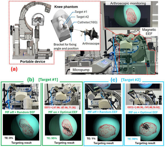
When the magnet was activated (ON), the generated magnetic flux successfully attracted and guided the particles along the predicted trajectory toward the target region. As a result, the targeting success rates reached 95% for target 1 and 99% for target 2, respectively. In contrast, when the magnetic field was deactivated (OFF), the injected particles followed the fluid streamlines and failed to reach the designated lesion areas, yielding only 0% and 1% arrival rates, respectively, as illustrated in Figure 6.
Figure 6.
(a) Experimental validation of MC navigation within the 3D knee phantom; (b) Navigation performance toward Target 1 under magnet OFF and ON modes; (c) Navigation performance toward Target 2 under magnet OFF and ON modes.
These results demonstrate that the optimized EEF configuration obtained from simulation can be directly utilized to control the real system, ensuring accurate magnetic actuation and consistent delivery of the magnetic MCs to the targeted cartilage region. The pronounced difference between the ON and OFF cases further highlights the strong correlation between the predicted field-flow dynamics and the experimental outcomes, thereby validating the physical fidelity and practical reliability of the proposed optimization framework.
To illustrate the advantages of integrating the optimization strategy with the PCTD system, Table 3 summarizes representative specifications in related studies together with the results of the present work. Unlike the electromagnetic systems in [13,21], which required multiple current-driven coils and high power consumption, the PCTD relies on a single permanent-magnet source and operates without electrical current, while still providing a clinically relevant hemispherical workspace. Building upon this hardware, the proposed optimization framework improves the targeting performance by at least 7% compared with empirical trials performed on the PCTD without optimization [19] and achieves a minimum of 15% increase in TE compared to previous work [13].
Table 3.
Comparison with other MSC-loaded MC navigation systems.
4. Conclusions and Future Work
In this study, a model-based navigation scheme is proposed using a portable curved telescopic device to achieve a comparable performance of the magnetic guidance of MSC-loaded microcarriers toward damaged cartilage regions during total knee arthroplasty. By leveraging a model-based optimization framework based on the physical dynamics of magnetic particle motion, the orientation and position of the end-effector were systematically optimized to minimize targeting error. The proposed approach effectively captured the interplay between magnetic force, fluidic drag force, and gravitational forces, enabling accurate simulation of the particle trajectory within a realistic knee phantom environment.
Simulation results demonstrated that the optimized EEF configuration achieved highly precise magnetic targeting, which was further confirmed through experimental trials. In experiments, when the magnet was activated, the targeting success rates reached 95% and 99% for two predefined targets, whereas negligible targeting was observed in the OFF condition. These findings confirm that the optimized EEF configuration can be directly applied to the real device, ensuring consistent and reliable magnetic actuation within the anatomical workspace. The proposed framework not only provides a compact and clinically compatible magnetic actuation platform but also establishes a unified modeling-to-control workflow that can be extended to other minimally invasive procedures.
While the results demonstrate strong performance, several limitations of the current work should be noted. First, the hydrodynamic environment was modeled using a simplified flow assumption, without incorporating local flow disturbances near cartilage surfaces or turbulence at the catheter tip. Second, the velocity field used in the particle-dynamics simulation was derived from a 2D profile mapped into the 3D joint cavity, which may not fully capture the spatial complexity of intra-articular fluid motion. Third, the long optimization time required pre-calculation before practical trials. Lastly, the catheter-tip position was predefined using a mechanical bracket, as illustrated in Figure 6, whereas clinical scenarios require automatic and patient-specific localization.
Future research will focus on addressing these limitations by considering the influence of more realistic joint-flow behaviors on particle transport, by incorporating parallel computation or pruning strategies to reduce runtime toward in situ implementation, and by integrating an automatic medical localization framework into the PCTD system to autonomously determine the injection position without relying on any fixed bracket for angle or position adjustment. These improvements are expected to enhance targeting accuracy and strengthen the adaptability of the system to patient-specific anatomies, further supporting its clinical translation. In addition, the medical-grade materials and appropriate sterilization pathways will also be considered to ensure compatibility with clinical standards.
Author Contributions
Conceptualization, N.T.T.N., K.T.N. and J.K.; methodology, N.T.T.N.; software, N.T.T.N. and M.C.H.; validation, N.T.T.N. and M.C.H.; formal analysis, N.T.T.N.; investigation, B.K., J.K. and K.T.N.; resources, N.T.T.N.; data curation, N.T.T.N.; writing—original draft preparation, N.T.T.N. and K.T.N.; writing—review and editing, B.K., J.K. and K.T.N.; visualization, B.K., J.K., J.-O.P. and K.T.N.; supervision, B.K., J.K. and K.T.N.; project administration, J.K. and J.-O.P.; funding acquisition, J.-O.P. All authors have read and agreed to the published version of the manuscript.
Funding
This work is supported by a grant of the Korean Health Technology R&D Project through the Korea Health Industry Development Institute (KHIDI), funded by the Ministry of Health & Welfare, Republic of Korea (grant number: RS-2023-00302154).
Data Availability Statement
Data can be provided on request.
Conflicts of Interest
The authors declare no conflicts of interest.
Abbreviations
The following abbreviations are used in this manuscript:
| KOA | Knee osteoarthritis |
| MSCs | Mesenchymal stem cells |
| MMS | Magnetic manipulation systems |
| PCTD | Portable curved telescopic device |
| MC | Microcarrier |
| DoF | Degrees of freedom |
| EEF | End effector |
| LS | Leg support |
| RMSE | Root mean square error |
| ROI | Region of interest |
| TE | Targeting efficiency |
References
- Cross, M.; Smith, E.; Hoy, D.; Nolte, S.; Ackerman, I.; Fransen, M.; Bridgett, L.; Williams, S.; Guillemin, F.; Hill, C.L.; et al. The Global Burden of Hip and Knee Osteoarthritis: Estimates from the Global Burden of Disease 2010 Study. Ann. Rheum. Dis. 2014, 73, 1323–1330. [Google Scholar] [CrossRef] [Scilit]
- Sophia Fox, A.J.; Bedi, A.; Rodeo, S.A. The Basic Science of Articular Cartilage: Structure, Composition, and Function. Sports Health 2009, 1, 461–468. [Google Scholar] [CrossRef] [Scilit] [PubMed]
- Cui, A.; Li, H.; Wang, D.; Zhong, J.; Chen, Y.; Lu, H. Global, Regional Prevalence, Incidence and Risk Factors of Knee Osteoarthritis in Population-Based Studies. EClinicalMedicine 2020, 29–30, 100587. [Google Scholar] [CrossRef] [Scilit] [PubMed]
- Talesa, G.R.; Manfreda, F.; Ceccarini, P.; Pace, V.; Antinolfi, P.; Rinonapoli, G.; Caraffa, A. The Treatment of Knee Cartilaginous Injuries: State of the Art. Acta Biomed. 2022, 93, e2022099. [Google Scholar] [CrossRef] [Scilit] [PubMed]
- Laver, L.; Marom, N.; Dnyanesh, L.; Mei-Dan, O.; Espregueira-Mendes, J.; Gobbi, A. PRP for Degenerative Cartilage Disease: A Systematic Review of Clinical Studies. Cartilage 2017, 8, 341–364. [Google Scholar]
- Richter, D.L.; Schenck, R.C.; Wascher, D.C.; Treme, G. Knee Articular Cartilage Repair and Restoration Techniques: A Review of the Literature. Sports Health 2016, 8, 153–160. [Google Scholar] [CrossRef] [Scilit]
- Davies, R.L.; Kuiper, N.J. Regenerative Medicine: A Review of the Evolution of Autologous Chondrocyte Implantation (ACI) Therapy. Bioengineering 2019, 6, 22. [Google Scholar] [CrossRef] [Scilit]
- Xiang, X.-N.; Zhu, S.-Y.; He, H.-C.; Yu, X.; Xu, Y.; He, C.-Q. Mesenchymal Stromal Cell-Based Therapy for Cartilage Regeneration in Knee Osteoarthritis. Stem Cell Res. Ther. 2022, 13, 14. [Google Scholar] [CrossRef] [Scilit]
- Giorgino, R.; Albano, D.; Fusco, S.; Peretti, G.M.; Mangiavini, L.; Messina, C. Knee Osteoarthritis: Epidemiology, Pathogenesis, and Mesenchymal Stem Cells: What Else Is New? An Update. Int. J. Mol. Sci. 2023, 24, 6405. [Google Scholar] [CrossRef] [Scilit]
- Law, J.; Yu, J.; Tang, W.; Gong, Z.; Wang, X.; Sun, Y. Micro/Nanorobotic Swarms: From Fundamentals to Functionalities. ACS Nano 2023, 17, 12971–12999. [Google Scholar] [CrossRef] [Scilit]
- Sitti, M.; Wiersma, D.S. Pros and Cons: Magnetic versus Optical Microrobots. Adv. Mater. 2020, 32, 1906766. [Google Scholar] [CrossRef] [Scilit] [PubMed]
- Yang, L.; Zhang, L. Motion Control in Magnetic Microrobotics: From Individual and Multiple Robots to Swarms. Annu. Rev. Control. Robot. Auton. Syst. 2021, 4, 509–534. [Google Scholar] [CrossRef] [Scilit]
- Go, G.; Jeong, S.-G.; Yoo, A.; Han, J.; Kang, B.; Kim, S.; Nguyen, K.T.; Jin, Z.; Kim, C.-S.; Seo, Y.R.; et al. Human Adipose–Derived Mesenchymal Stem Cell–Based Medical Microrobot System for Knee Cartilage Regeneration in Vivo. Sci. Robot. 2020, 5, 6626. [Google Scholar] [CrossRef] [Scilit] [PubMed]
- Li, J.; Li, X.; Luo, T.; Wang, R.; Liu, C.; Chen, S.; Li, D.; Yue, J.; Cheng, S.; Sun, D. Development of a Magnetic Microrobot for Carrying and Delivering Targeted Cells. Sci. Robot. 2018, 3, eaat8829. [Google Scholar] [CrossRef] [Scilit]
- Jeon, S.; Kim, S.W.S.Y.S.; Ha, S.; Lee, S.; Kim, E.; Kim, S.W.S.Y.S.; Park, S.H.; Jeon, J.H.; Kim, S.W.S.Y.S.; Moon, C.; et al. Magnetically Actuated Microrobots as a Platform for Stem Cell Transplantation. Sci. Robot. 2019, 4, eaav4317. [Google Scholar] [CrossRef] [Scilit]
- Yasa, I.C.; Tabak, A.F.; Yasa, O.; Ceylan, H.; Sitti, M. 3D-Printed Microrobotic Transporters with Recapitulated Stem Cell Niche for Programmable and Active Cell Delivery. Adv. Funct. Mater. 2019, 29, 1808992. [Google Scholar] [CrossRef] [Scilit]
- Jeon, S.; Park, S.H.; Kim, E.; Kim, J.; Kim, S.W.; Choi, H. A Magnetically Powered Stem Cell-Based Microrobot for Minimally Invasive Stem Cell Delivery via the Intranasal Pathway in a Mouse Brain. Adv. Healthc. Mater. 2021, 10, 2100801. [Google Scholar] [CrossRef] [Scilit]
- Chen, X.-Z.; Liu, J.-H.; Dong, M.; Müller, L.; Chatzipirpiridis, G.; Hu, C.; Terzopoulou, A.; Torlakcik, H.; Wang, X.; Mushtaq, F.; et al. Magnetically Driven Piezoelectric Soft Microswimmers for Neuron-like Cell Delivery and Neuronal Differentiation. Mater. Horizons 2019, 6, 1512–1516. [Google Scholar] [CrossRef] [Scilit]
- Nguyen, K.T.; Thi Nguyen, N.T.; Park, J.; Kim, J. A Portable Assistant System for Knee Treatment Based on Curved Telescopic Mechanism. Sensors Actuators A Phys. Actuators A Phys. 2025, 397, 117287. [Google Scholar] [CrossRef] [Scilit]
- Nguyen, K.T.; Kee, H.; Go, G.; Kim, S.; Choi, E.; Park, J.; Park, S.; Kim, J. Field-Free Region Scanning-Based Magnetic Microcarrier Targeting in Multibifurcation Vessels. Adv. Intell. Syst. 2024, 6, 2300700. [Google Scholar] [CrossRef] [Scilit]
- Huang, H.; Li, J.; Wang, C.; Xing, L.; Cao, H.; Wang, C. Using Decellularized Magnetic Microrobots to Deliver Functional Cells for Cartilage Regeneration. Small 2024, 20, e2304088. [Google Scholar] [CrossRef] [Scilit]

Disclaimer/Publisher’s Note: The statements, opinions and data contained in all publications are solely those of the individual author(s) and contributor(s) and not of MDPI and/or the editor(s). MDPI and/or the editor(s) disclaim responsibility for any injury to people or property resulting from any ideas, methods, instructions or products referred to in the content. |
© 2026 by the authors. Licensee MDPI, Basel, Switzerland. This article is an open access article distributed under the terms and conditions of the Creative Commons Attribution (CC BY) license.