


Abstract
This paper presents a torque oscillation attenuation method for permanent magnet synchronous motors (PMSMs) based on the combination of sliding-mode control (SMC) and the equivalent input disturbance (EID) approach. To deal with the changes in PMSM parameters, we explored a continuous-domain ant colony optimization (CDACO) method to design a control system for such a plant. This is the first application of SMC-EID to uncertain PMSM plants, with CDACO enabling robust parameter tuning in continuous spaces. First, we designed an EID estimator to estimate the disturbance caused by torque oscillation. Next, we added the estimated disturbance to the sliding-mode controller to improve disturbance attenuation performance. Then, we extended an ant colony optimization (ACO) algorithm to the continuous domain to optimize controller parameters for an uncertain plant. Finally, a speed control experiment was carried out on a two-mass experimental system for PMSMs to demonstrate the validity of the method. The experimental results show that our method yields better control performance than the SMC.
1. Introduction
A permanent magnet synchronous motor (PMSM) has many advantages, including a simple structure, a large torque, and high efficiency and reliability [1]. It has been widely used in industrial robots [2], conveyors [3], drilling machines [4], and many other industrial applications. However, it is difficult to achieve high-precision control of a PMSM servo system because it is affected by disturbances [5].
Torque oscillations are critical for PMSMs because they degrade the control performance of PMSM servo systems [6]. Thus, suppressing torque oscillations is an important figure of merit for PMSMs in the application of electrical vehicle traction, especially in low-speed operations [7]. It has been extensively investigated in the literature. Approaches are mainly divided into two categories: design-based and control-based [8]. The former focuses on optimizing the geometric structures of stators and rotors to minimize torque oscillations [9]. The latter focuses on designing control strategies to smooth the PMSM torque [10].
Control-based approaches can be used to further mitigate torque oscillations for a suitably designed physical structure. Sliding-mode control (SMC) [11], active disturbance rejection methods [12], and many other advanced control strategies have been applied to PMSM control systems to achieve high control precision. The SMC system has been widely used in control practice due to its simple structure, fast dynamic response, and strong disturbance attenuation [13]. However, such a system requires disturbance information in the design of a sliding-mode controller. Moreover, there is a trade-off between disturbance attenuation performance and chattering for SMC systems. More specifically, the high gain of a sliding-mode controller guarantees disturbance attenuation performance, but it leads to a chattering phenomenon. Thus, SMC has been modified to reduce chattering from various angles, such as high-order SMC [14], integral SMC [15], and a reaching-law method [16]. However, these methods have complex structures and relatively difficult design methods. Recent advanced SMC methods, including disturbance-observer-based SMC for synchronous reluctance motors [17] and linear-extended-state-observer-based terminal SMC for PMSMs [18], manage to actively estimate and attenuate disturbances, but these lack handling of uncertainties.
Active disturbance rejection methods use observers to estimate and compensate for disturbances actively. The equivalent input disturbance (EID) approach is one of these methods. An EID is a signal on the control input channel of a plant that produces the same effect on the output as actual disturbances do [19]. Compared to active disturbance rejection control (ADRC), disturbance-observer-based control (DOBC), and other active disturbance rejection methods, the EID approach has its unique advantages. Unlike ADRC, the configuration of an EID system is relatively simple; unlike DOBC, it does not require an inverse model of a plant. It yields satisfactory disturbance attenuation performance in many applications, such as vibration depression of buildings [20], quadrotor control [21], and servo systems [22]. It is worth mentioning that the system stability and control performance of an SMC system are ensured by a low gain of the sliding-mode controller if the system uses the information of a disturbance.
Several studies have demonstrated the potential to improve the oscillation attenuation performance of PMSMs by combining SMC and EID approaches. Refs. [23,24] incorporated EID into a conventional SMC system. These two studies allowed SMC to reject unmatched disturbances and calculate the stability domain of SMC switching gains. However, they did not explain how to choose specific SMC switching gains. Refs. [25,26] used SMC as the controller in an EID system. These two methods improved the dynamic performance of the control system. Nevertheless, they did not give the method for designing SMC parameters. Ref. [27] used an SMC controller to suppress the estimation error that the conventional EID approach neglected. This study managed to ensure system stability with a low switching gain, which produced little chattering compared to conventional SMC. However, it used the method of enlarging and reducing to design the switching gain. There was conservativeness in the process. These studies proved that the combination of SMC and EID improved the control performance and produced little chattering with a low switching gain. In PMSM servo systems, the moment of inertia and the viscous friction coefficient may change with time and operating environments. However, up to now, the SMC-EID method has only been used to handle plants without uncertainties. It is challenging to extend SMC-EID to plants with uncertainties.
Intelligent optimization algorithms provide a way to address the design problem of uncertain systems. Among these algorithms, the ant colony optimization (ACO) algorithm is a reliable population-based algorithm mimicking ant foraging behavior for solving discrete problems [28]. It is a multi-agent meta-heuristic optimization method. ACO algorithms involve simple agents (ants) that cooperate with each other to achieve an emergent unified behavior for a system. They are capable of finding high-quality solutions for problems with a large search space [29]. Note that the solution of the ACO is obtained from a finite set of discrete combinations [30]. The optimization of SMC parameters requires finding a solution in a continuous solution space. How to extend the ACO method to a continuous solution space is a critical problem.
In this study, we combine the EID and SMC methods to attenuate torque oscillation in an uncertain plant. We extend ACO to a continuous solution space and name it continuous-domain ant colony optimization (CDACO) for designing control systems for such plants. Unlike these prior works [23,24,25,26,27], which only handled plants without uncertainties and focused on the switch gain design, we address uncertainties via CDACO, providing a systematic multi-parameter design for real-world variations in PMSM servo systems, where the moment of inertia and the viscous friction coefficient may change with time and operating environments. The basic idea was presented in [31]. This paper is a significant improvement over that paper: the plant is uncertain, and we developed a CDACO algorithm to design the control system for such a plant. In the rest of this paper, first, we analyze the disturbances in PMSM servo systems. Next, we present a system configuration that combines the EID and SMC methods for a PMSM. Then, we develop a CDACO algorithm to design the SMC-EID-based control system for an uncertain plant. Finally, experiments verify its validity. The main contributions of this article are as follows:
- (1)
- We applied the SMC-EID method to an uncertain system. SMC-EID attenuates a disturbance effectively and achieves a fast response while having little chattering.
- (2)
- We extended the discrete ACO to a continuous solution space and developed a CDACO algorithm.
- (3)
- We used the CDACO algorithm to design the control system for an uncertain plant. CDACO optimizes the integral of timed square error (ITSE) of an uncertain system to design the SMC parameters.In this paper, , and means the maximum singular value of D. is the Laplace transform of and is the inverse Laplace transform.
2. Torque Oscillations in PMSM Servo Systems
A basic control strategy for a PMSM drive is vector control. The following model of a PMSM (Table 1) is used for this purpose:
where the subscripts d and q mean the direct and quadrature axes, respectively.
Table 1.
PMSM parameters ().
The oscillation torque, , is mainly caused by a cogging torque and a torque ripple. A cogging torque results from the structure of the motor, also known as a position-dependent torque. A torque ripple is caused by the flux linkage between the permanent magnet and the stator currents. Based on [9], we analyze and model the torque oscillation in PMSMs.
2.1. Cogging Torque
The interaction between the permanent magnet flux and the magnetic conductance generated by the stator slot is the source of cogging torque, which is determined by its fundamental and harmonic waves. The period of the torque is
where is the least common multiple between the number of stator slots and pole pairs .
The interaction between the direct current component of permanent magnet flux and the harmonic interaction of magnetic conductance is another source of the cogging torque. Similarly, the period of the torque is
where is the least common multiple between the number of stator slots and rotor slots.
As a result, the cogging torque is
where and are the amplitudes of the cogging torque and is the electrical angle.
2.2. Torque Ripple
Due to a non-sinusoidal flux density distribution in air gaps, the resultant flux linkage between the permanent magnet and the stator currents contains the harmonics in the a-b-c frame.
The corresponding flux linkage appears as the 6th and its multiple harmonics, which are expressed as
where , , and are the DC, the 6th, and the 12th harmonic terms of the d-axis flux linkage and is the electrical angle.
The effect of a torque ripple is
The cogging torque and the torque ripple are both functions of the angle . Thus, the oscillation torque contains both of them:
The disturbance model in (7) is derived from physical principles underlying PMSM torque oscillations. Cogging torque arises from the interaction between the permanent magnet flux and stator slot reluctance, with periods and determined by the least common multiple of stator slots and rotor poles, leading to periodic harmonics. Torque ripple originates from non-sinusoidal flux and current harmonics, typically dominated by 6th-order multiples in three-phase systems. It is a disturbance that relates to the angles of the motor. Its frequencies vary with the speed of the PMSM. As the EID approach attenuates disturbances in a wide frequency range, we combine the SMC and EID methods to achieve a fast response and satisfy torque oscillation attenuation.
3. SMC-EID System for PMSM
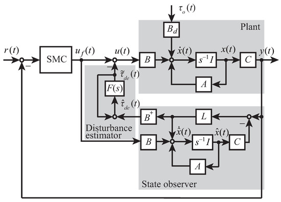
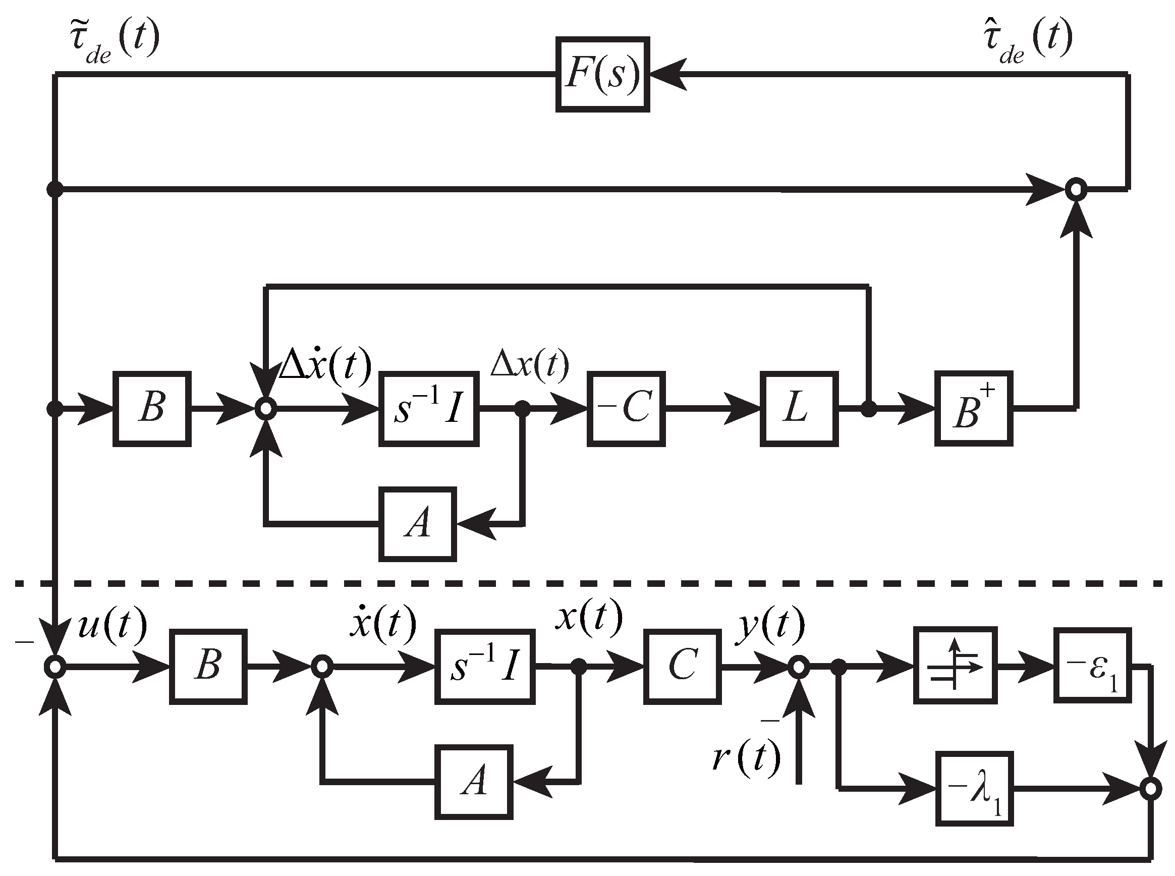
The configuration of an SMC-EID control system (Figure 1) has four parts: a plant, an SMC, a state observer, and a disturbance estimator. This section explains the basic structure and configuration of the EID approach.
Figure 1.
Configuration of SMC-EID.
This study considers a surface-mounted PMSM, in which . Let , which is widely used to control such a PMSM. Thus, (1) becomes
Define
state variables and the control input as
respectively. Then,
The inductor of the q-axis is usually small for a small-size PMSM (less than 10 mH). Thus, we assume that
This allows us to write (10) as
Since a voltage compensator is usually used to compensate for , the model of the PMSM, (10), with a voltage compensator becomes
Define the sliding surface as
The control input of a conventional SMC system without EID is
3.1. Basic Structure of EID Approach
A linear plant with a disturbance
can be interpreted as a plant with an EID [32], , that is,
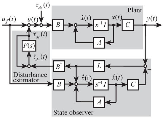
She et al. devised a method to produce an estimate of in a simple way (Figure 2) [19]. A full-order observer is used to estimate it.
Figure 2.
Basic configuration of EID approach.
The observer is
where is the reconstructed state of , is the output of the observer, is the control input of the observer, and L is the observer gain. Then
An estimate of the EID [19] is
where
and
A low-pass filter is used to select the estimation frequency band. It satisfies
where is the highest angular frequency for disturbance attenuation. is the filtered signal of :
3.2. Stability Analysis
We should design the low-pass filter and the observer gain so that they do not destroy the stability of the whole system. Let
The plant (18) is
Substituting (21) into (22) yields
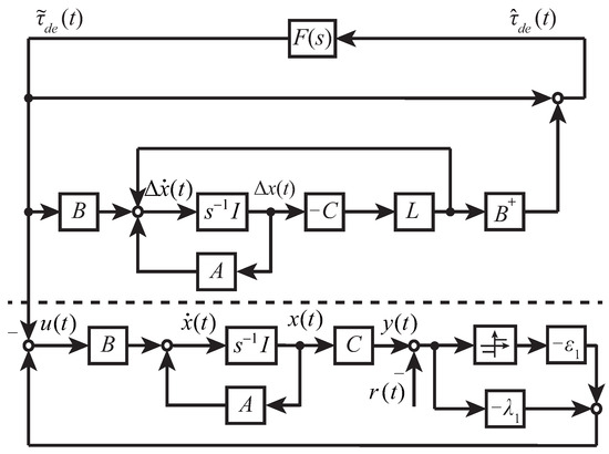
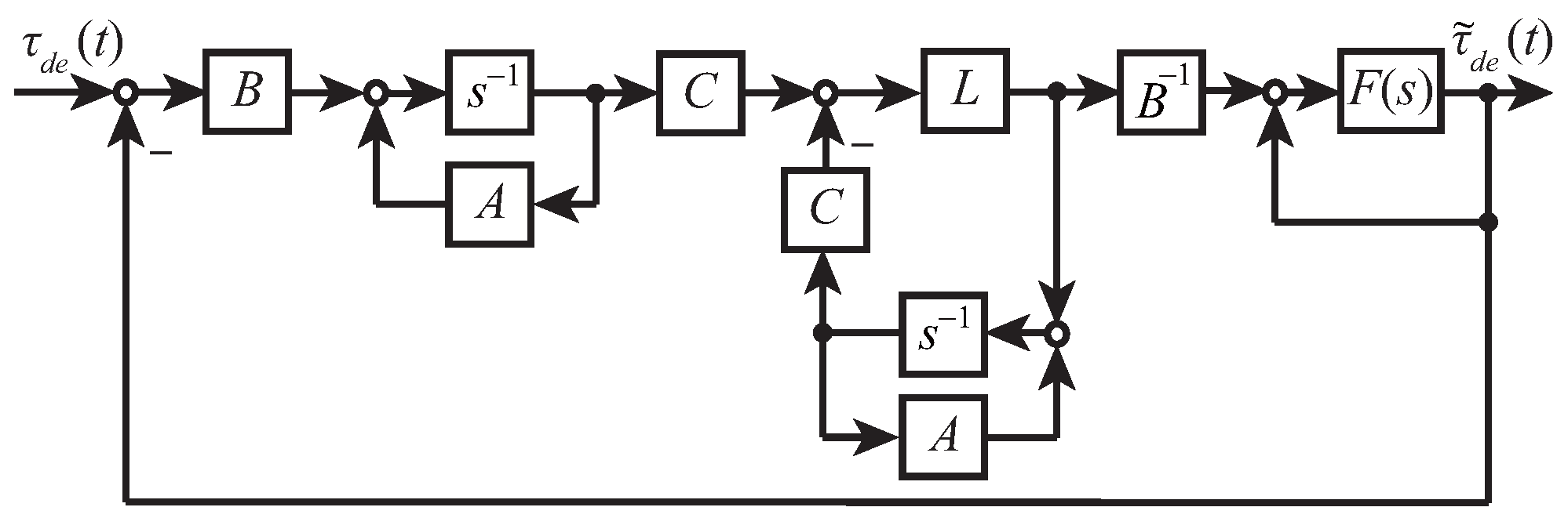
Combining (27), (29), and (30), and redrawing Figure 1, yields Figure 3.
Figure 3.
Block diagram of SMC-EID.
The stability conditions for the improved servo system are broken down into two parts. First, the control law (21) guarantees the stability of the EID system. Second, the feedback control system is stable.
The transfer function from to is
Theorem 1.
When the system is under the following conditions, (21) guarantees the stability of the control system.
- (1)
- is stable.
- (2)
- . Here, , and means the maximum sigular value of G.
The feedback system is an SMC system. The sliding surface is defined in (14). The parameters of the state-space Formula (18) for the PMSM (13) are
The derivative of with time is
The controller is designed as (15). Then,
Define a Lyapunov function
The system is stable when
Then
In (37), when and , . We need to design to ensure that
It is obvious that (38) holds when the control gain satisfies
Thus, the system is stable when Theorem 1 and (39) hold.
4. Design of EID Estimator and SMC
This section explains the design of the EID estimator and the parameters of the SMC-EID system (c, , k, and ).
4.1. EID Estimator Design
Two elements need to be selected for the EID estimation and compensation: the low-pass filter and the observer gain L.
An appropriate low-pass filter ensures disturbance attenuation performance. A first-order low-pass filter is designed:
where is used to regulate the angular-frequency band for disturbance attenuation. The cutoff angular frequency .
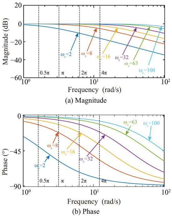
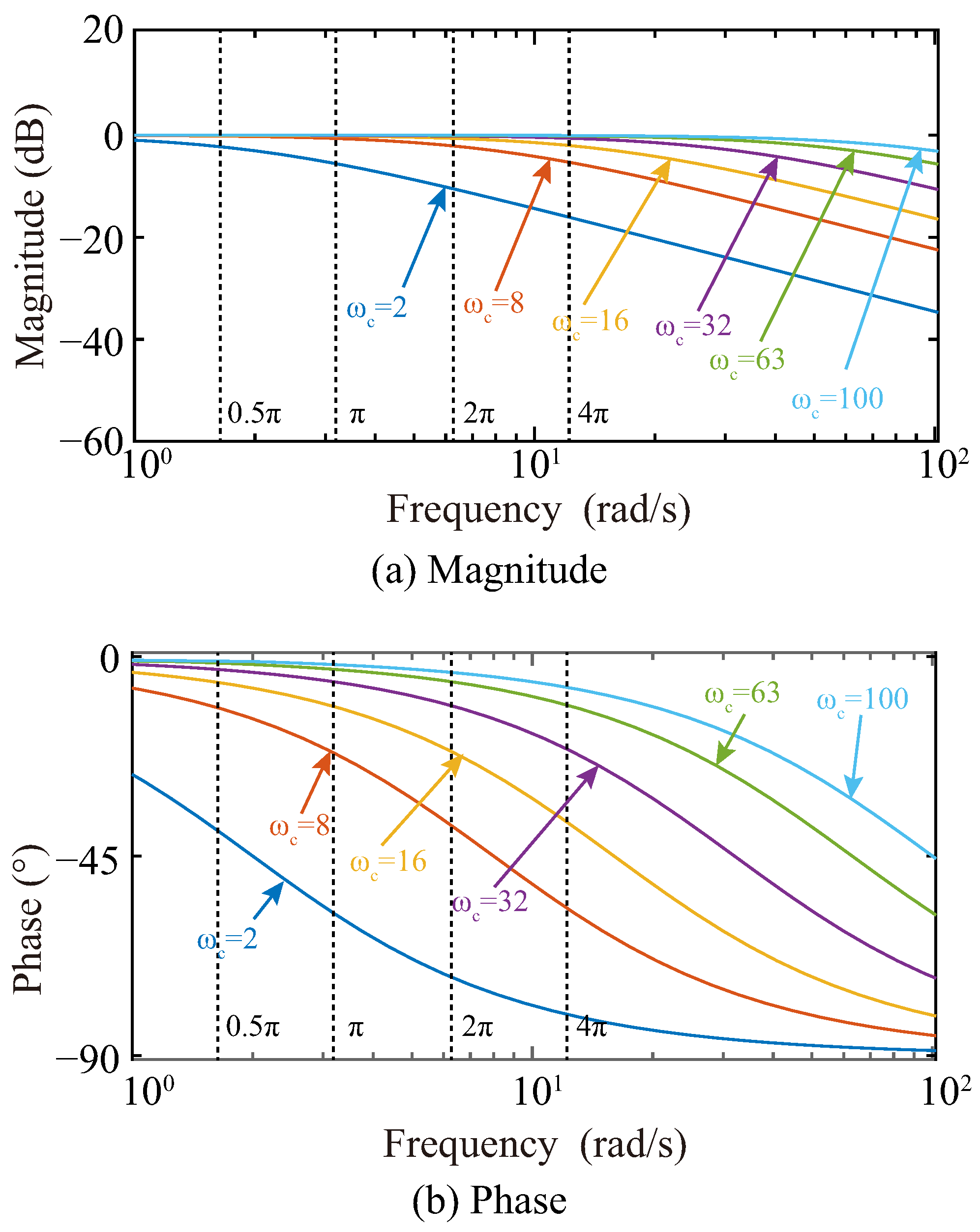
To investigate the relationship between the cutoff angular frequency and the disturbance attenuation performance, we chose a set of cutoff angular frequencies of 100, 63, 32, 16, 8, and 2 rad/s and drew Bode diagrams (Figure 4). When the cutoff angular frequency of the low-pass filter is five times higher than a disturbance component, the component of the disturbance estimate passes the filter with virtually no gain attenuation or phase lag.
Figure 4.
Bode plot of : (a) magnitude and (b) phase.
But if the angular-frequency band is too wide, it cannot attenuate high-frequency noise in the system. Thus, is chosen as [32]
where in (41) is the highest angular frequency of disturbances. Thus,
where is the angular-frequency band for disturbance attenuation.
After we choose an appropriate , we need to design an observer gain L that ensures is small enough.
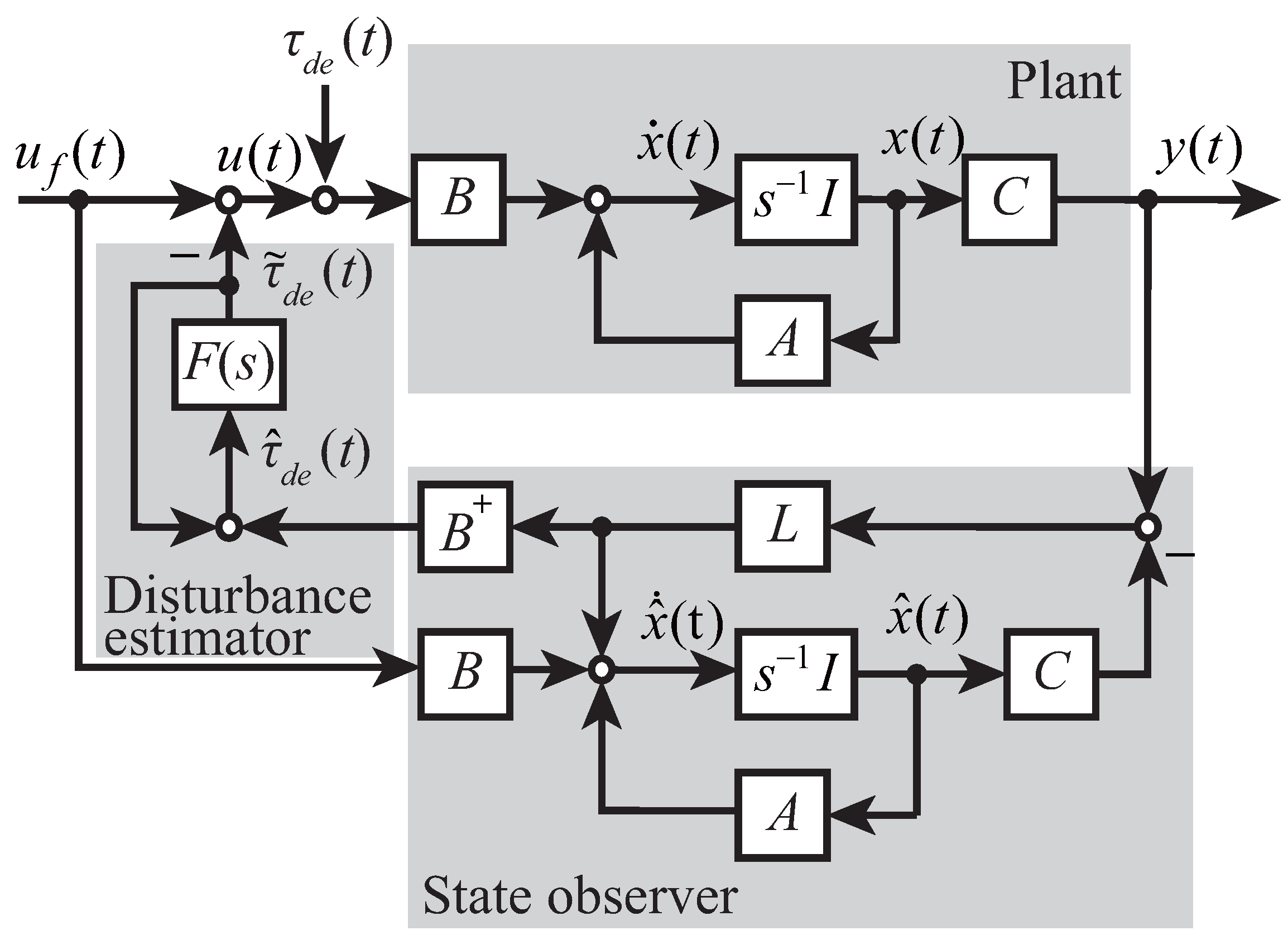
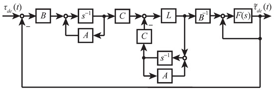
Figure 5.
EID configuration for disturbance estimate analysis.
The system is a unity feedback system and . The open-loop transfer function is
Thus, the closed-loop transfer function from to is
Then, the transfer function from to is
According to the Routh Criterion, it is stable when
can be interpreted as
We choose an L that ensures
can be represented by
When is large enough that
Then,
Thus,
As the zero and the pole are close to each other, and they are both far from other zeros and poles, they result in zero-pole cancellation. Then,
According to (41),
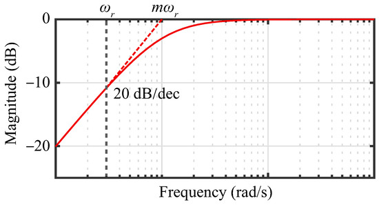
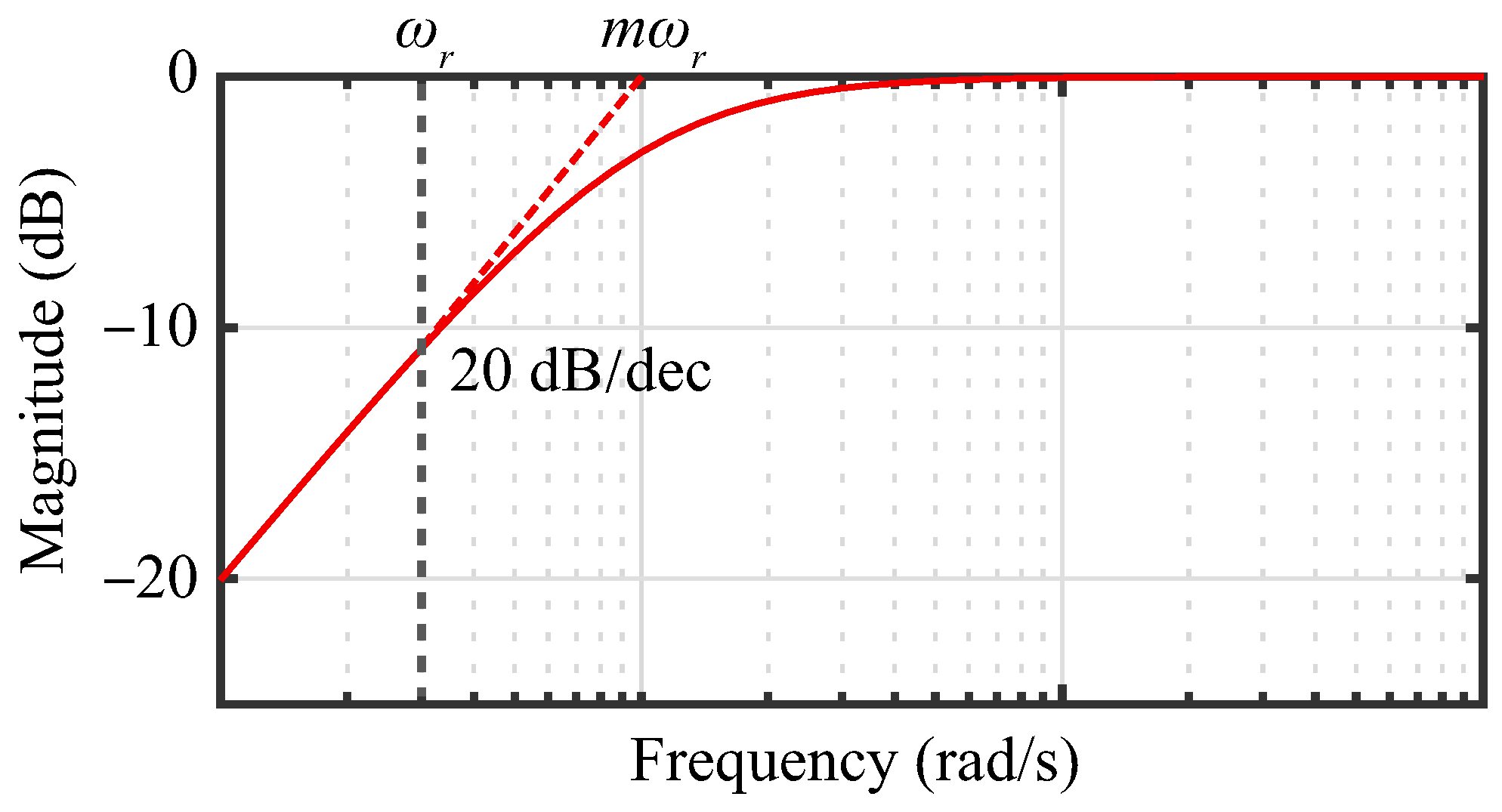
From the Bode diagram of is shown as Figure 6.
Figure 6.
Bode diagram of . The solid line represents the exact frequency response, while the dashed line denotes the asymptotic magnitude characteristic indicating the slope and cutoff frequency.
When the disturbance frequency satisfies
the inequality below holds.
4.2. Ant Colony Optimization-Based SMC Design
We replaced the sign function in SMC with a saturation function to further suppress chattering. As a result, the SMC-EID in this study is
where
and the positive constant k is the linear region of the saturation function. As shown in (14), c should be a positive real number. Thus, is chosen for the design of , , and in (57). As there are uncertainties in the system, we set up a group of systems with different parameters. The number of systems is N. The optimal set of control parameters should show great control performance in all systems.
is the switching gain of the SMC and is the gradient of the saturation function. The smaller is, the closer to a sign function the saturation function is. While the combination of a larger and a smaller yields better disturbance attenuation performance, it produces larger chattering. The chattering is bounded by the saturation function , limiting amplitude to . is a proportional control gain. The larger it is, the faster the dynamic response is and the larger the overshoot is.
This study developed a method of designing the SMC parameters based on CDACO to solve the problem.
A conventional ACO solution space is usually a discrete solution space. However, this study needs to find a solution in a continuous solution space.
Let an ant be . The pheromone of Ant n in the ith iteration is
where p is a weight of the performance index, which is a positive constant indicating the transition performance; is a forgetting factor; and is the weighted average of . is the ITSE of the n-th system:
is small when
- (1)
- Settling time is short;
- (2)
- Overshoot is small;
- (3)
- Chattering is little;
- (4)
- Static error is eliminated.
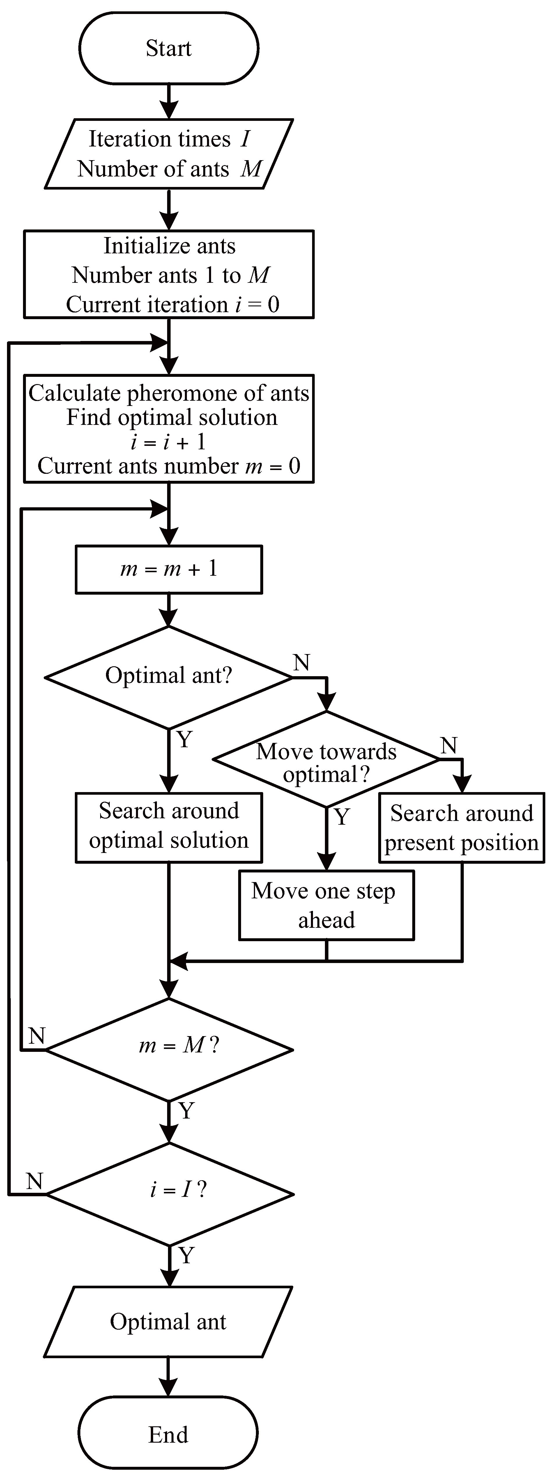
evaluates the control performance comprehensively. The smaller is, the better the overall control performance is. The optimal ant has the smallest performance index and the largest pheromone (), that is, a small speed fluctuation and small chattering. It searches around itself and looks for a better solution.
Other ants calculate their transition probabilities. For example, the probability of Ant n is
Thus, a low pheromone means the ant has a high transition probability of moving toward the optimal solution. If it decides not to do so, then it searches around itself.
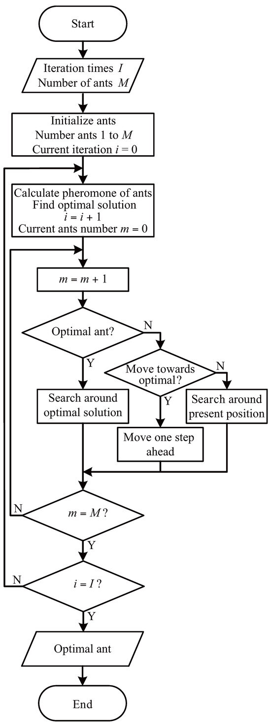
We condense the above discussion as follows:
- CDACO algorithm:(Step 1) Set the number of ants M, evaporation rate , initial pheromone , and max iteration times I. Generate initial ants uniformly in the search space justified by the lower bound from (39) to ensure stability and the upper bound to avoid excessive gain.
- (Step 2) Update the pheromone for each ant using (59).
- (Step 3) Calculate the transition probability for each ant using (61) and make a decision by sampling from Gaussian probability.
- (Step 4) Go to (Step 2) and repeat until reaching the iteration times.
The flow chart of CDACO (Figure 7) further clarifies the CDACO procedure.
Figure 7.
Flow chart of CDACO.
The performance of CDACO depends on the number of ants M, the number of iteration times I, the weight of the performance index p, the forgetting factor , and the performance index . Note that a large means that the pheromone depends strongly on the current state, and a large p means a high transition probability .
5. Experimental Verification
Table 2.
Nominal PMSM specifications.
Let the reference input be
and the disturbance model is derived from PMSM torque oscillations (7)
where is the mechanical angle of the PMSM. Since the target angular velocity of the PMSM is 500 rpm, which is approximately 50 rad/s, the angular frequencies in the disturbance are about 5 rad/s, 10 rad/s, and 300 rad/s. Note that torque oscillations at 300 rad/s or higher have little influence on the PMSM system. was chosen to be 10 rad/s and the low-pass filter to be
According to (48) and (50) and ensuring observer performance, the time constant of the observer should be less than one-tenth of that of the plant. Thus, the observer gain L is chosen to be
The CDACO algorithm was established in MATLAB 2020b/Simulink and the parameters optimized offline. We set up different systems with different moments of inertia and viscous friction coefficients, which simulate the uncertainties in the system. Among them, the moment of inertia kg and the viscous friction coefficients N/rad. Thus, there are nine different systems with different parameters. The system whose kg and N/rad is the nominal system. Its performance index is . The performance indexes of other systems are . E is calculated as follows:
It guarantees the robustness of the system.
The SMC-EID, (57), has three parameters, , , and , that need designing. According to (39), we choose . Thus, the range of is
Then, we set the search space to be
Setting the parameters of CDACO (Table 3), uniformly generating the first generation of ants in the search space, (69), and optimizing , , and in (57) yields
Table 3.
Parameters of CDACO.
For comparison, we used CDACO to optimize the parameters in a conventional SMC
The conventional SMC is designed with the same CDACO, sliding surface (14), and nine identical uncertain systems as the SMC-EID method. Optimizing gives
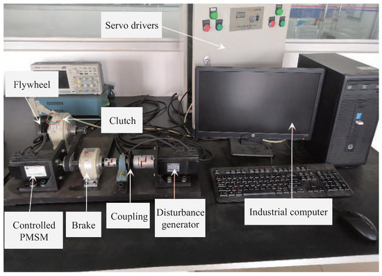
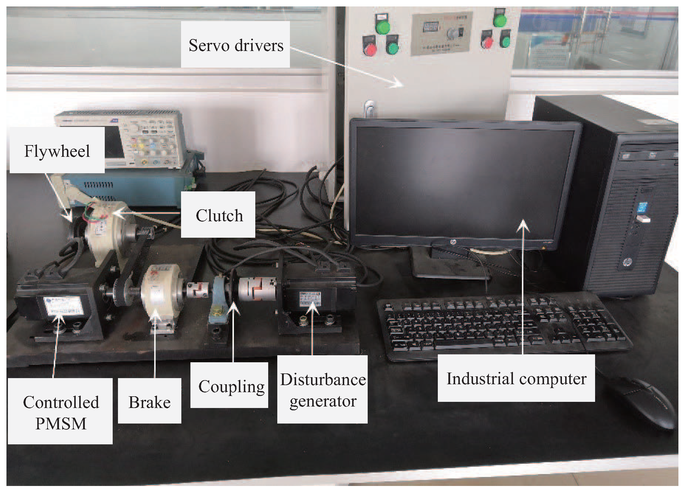
A two-mass experimental system (Figure 8) was used to demonstrate the validity of the method. It has two identical PMSMs: one is used as a plant, and the other is a disturbance generator. It has a clutch that controls the engagement and disengagement of the flywheel, thereby changing the system’s rotational inertia. The nameplate values of the PMSMs are summarized in Table 4.
Figure 8.
Two-mass experimental system.
Table 4.
PMSM nameplate values.
MATLAB R2020b was used to design a control system. TwinCAT 3 was used to perform system control with a sampling period of 500 μs.
We conducted four sets of comparative experiments with different moments of inertia J and reference speeds r. The four experimental conditions are shown as follows:
- Exp. 1: = 0.004 and = 500 rpm;
- Exp. 2: = 0.004 and = 250 rpm;
- Exp. 3: = 0.006 and = 500 rpm;
- Exp. 4: = 0.006 and = 250 rpm.
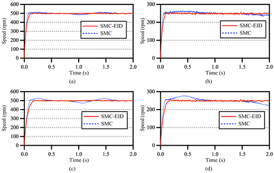
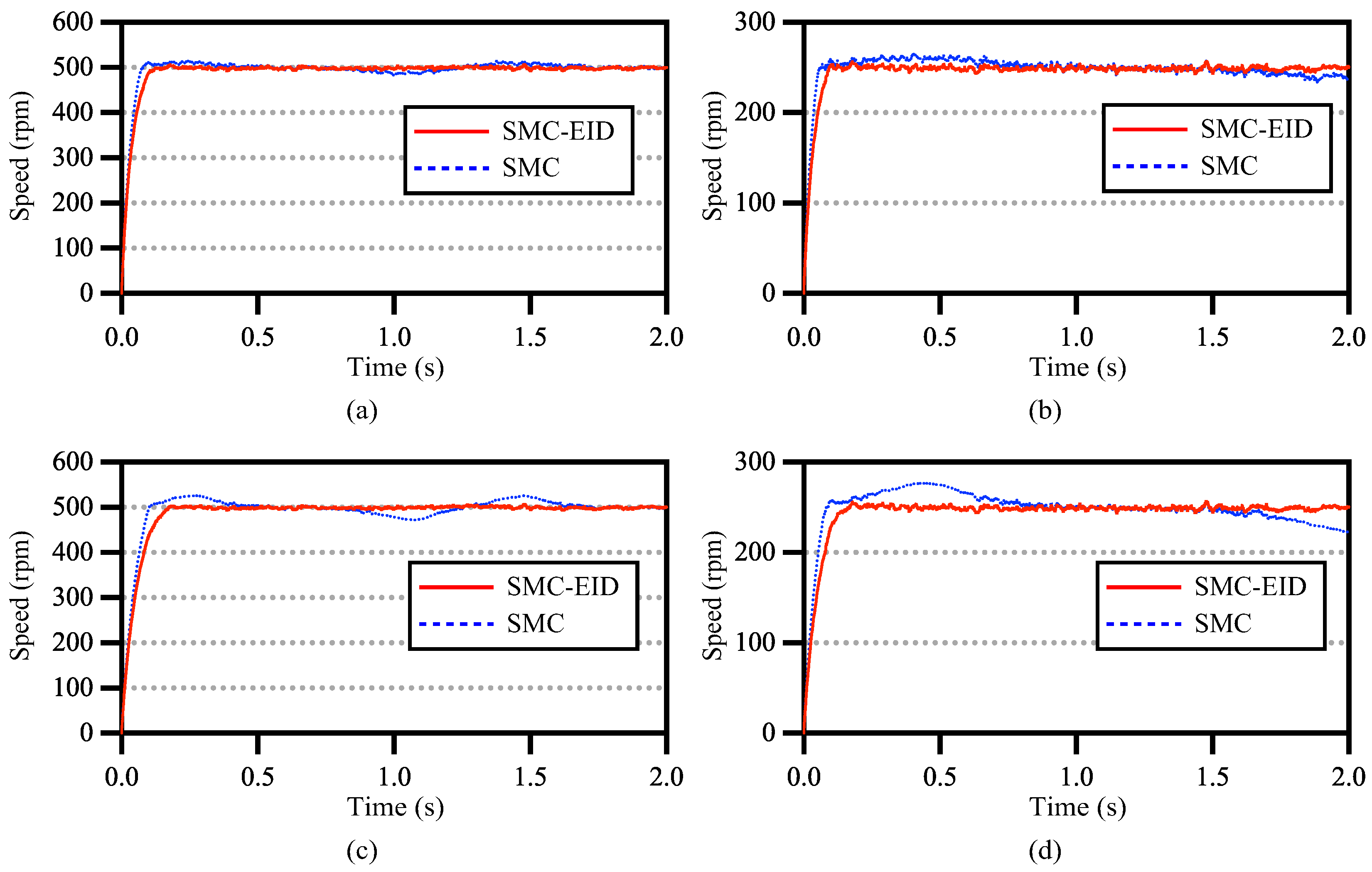
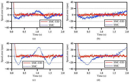
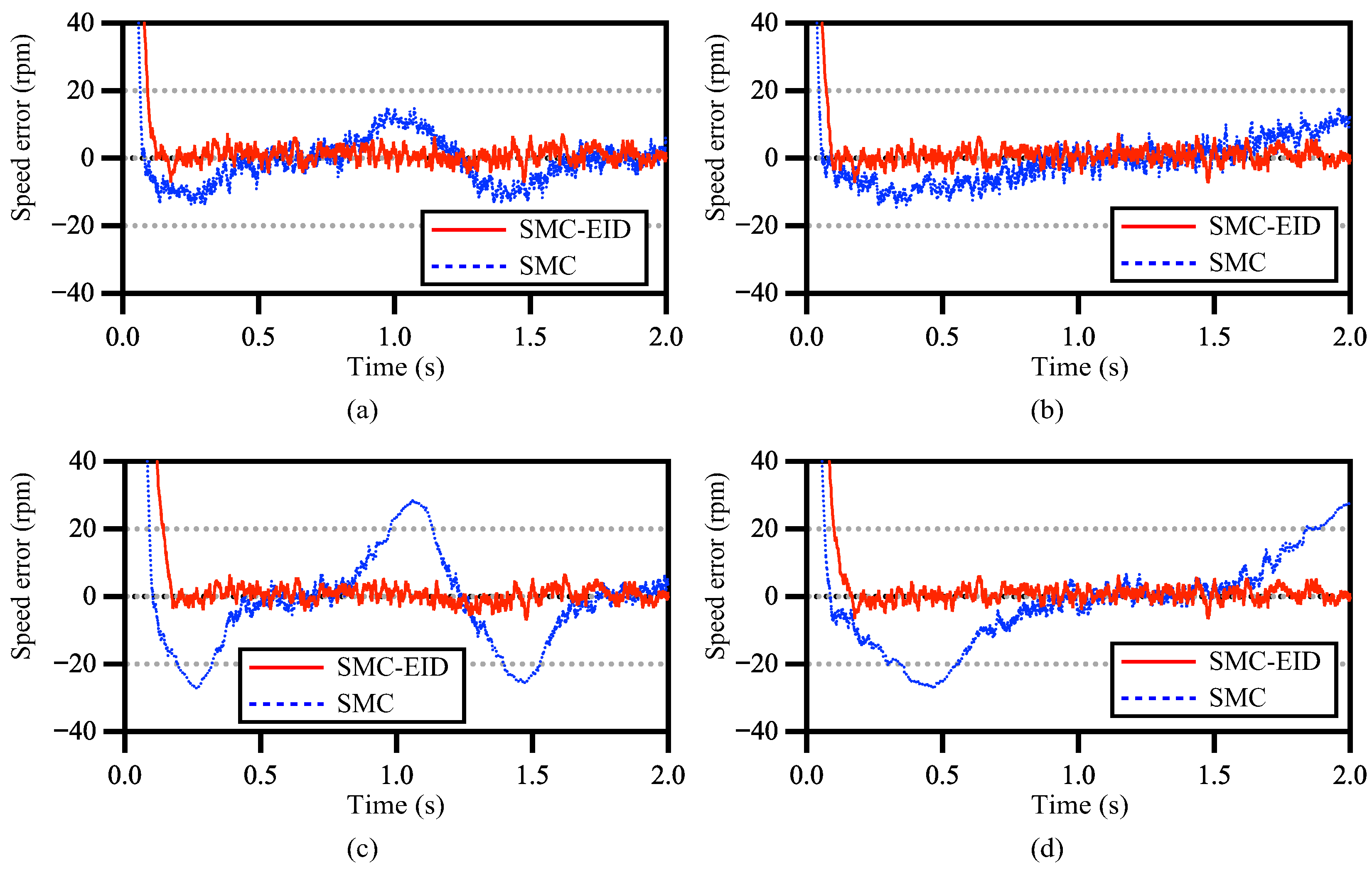
The speed response (Figure 9) and speed error (Figure 10) show that the disturbance was attenuated to a lower level for the SMC-EID than for the SMC. A comparison between performance indexes (Table 5) reveals that in all four experiments, the peak-to-peak (PP) speed error and ITSE of the SMC-EID are all less than those of the conventional SMC. The average PP speed error of the SMC-EID is about 37% of that of the conventional SMC, and the average ITSE of the SMC-EID is about 35% of that of the conventional SMC.
Figure 9.
Comparison of speed response between SMC-EID and conventional SMC in different sets of experiments: (a) Exp. 1, (b) Exp. 2, (c) Exp. 3, and (d) Exp. 4.
Figure 10.
Comparison of speed error between SMC-EID and conventional SMC in different sets of experiments: (a) Exp. 1, (b) Exp. 2, (c) Exp. 3, and (d) Exp. 4.
Table 5.
Control performance comparison (PP: peak-to-peak).
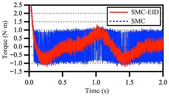
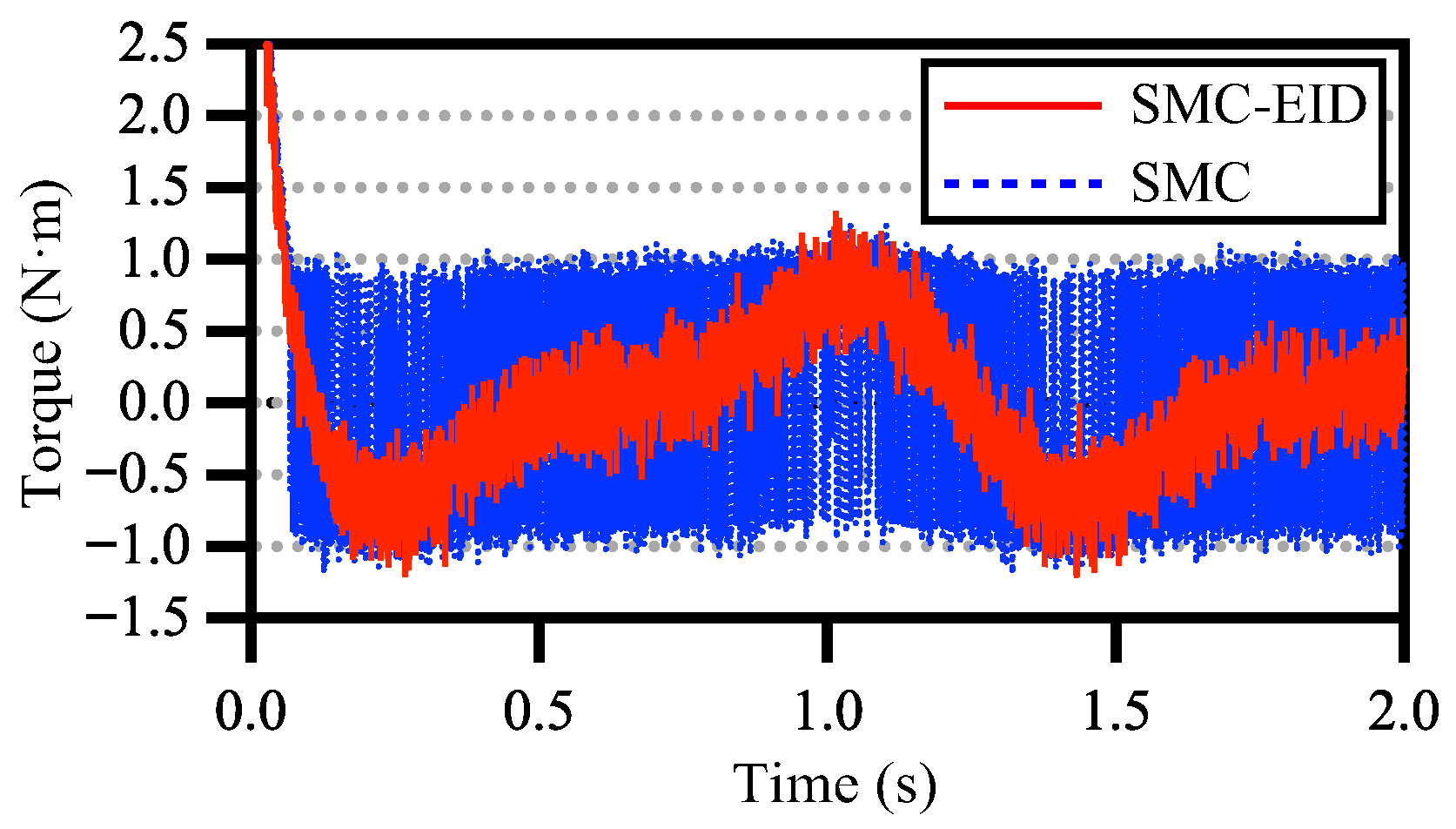
We take Exp. 1 as an example. The torque comparison (Figure 11) between SMC-EID and conventional SMC shows that the chattering is much smaller for the SMC-EID than for the SMC.
Figure 11.
Torque comparison between SMC and SMC-EID in Exp (1).
6. Conclusions
This paper explained a control method that combines the SMC and EID methods for uncertain systems. We added an EID estimate to a sliding-mode controller, not only to improve the disturbance attenuation performance but also to reduce chattering. Then, CDACO solves the design problem of uncertain systems. This method has significant advantages:
- (1)
- Our method extends the SMC-EID method to uncertain plants, demonstrated by stability analysis and optimization over nine uncertain systems.
- (2)
- The novel CDACO algorithm handles continuous optimization spaces and solves the multi-parameter design problem for uncertain systems.
- (3)
- Experimental results validate superior control performance compared to conventional SMC. In the four experiments, the average PP speed error of the SMC-EID method was about 37% of that of the conventional SMC, and the ITSE of SMC-EID was about 35% of that of the conventional SMC.
Author Contributions
Conceptualization, R.J. and J.S.; methodology, R.J., X.Y. and J.S.; software, R.J. and F.W.; validation, R.J. and X.Y.; formal analysis, R.J. and J.S.; investigation, R.J. and J.S.; resources, R.J., J.S., F.W. and S.K.; data curation, R.J.; writing—original draft preparation, R.J., X.Y. and J.S.; writing—review and editing, R.J., X.Y., J.S., F.W. and S.K.; visualization, R.J., J.S., F.W. and S.K.; supervision, J.S., F.W. and S.K.; project administration, X.Y, S.K. and J.S.; funding acquisition, X.Y, S.K. and J.S. All authors have read and agreed to the published version of the manuscript.
Funding
This work was supported in part by the Beijing Natural Science Foundation under Grant 4244089; the Fundamental Research Funds for the Central Universities, China University of Geosciences (Wuhan) under Grant CUG240635; the “CUG Scholar” Scientific Research Funds at China University of Geosciences (Wuhan) under Grant 2022029; the Natural Science Foundation of Hubei Province, China under Grant 2020CFA031; and JSPS (Japan Society for the Promotion of Science) KAKENHI under Grants 23K25252 and 24K03325.
Institutional Review Board Statement
Not applicable.
Informed Consent Statement
Not applicable.
Data Availability Statement
Data are available at URL (accessed on 23 Jan 2026): https://pan.baidu.com/s/17rgN6X47Ig7ePO9mR8q28A?pwd=jjii Password: jjii.
Conflicts of Interest
The authors declare no conflicts of interest.
Abbreviations
The following abbreviations are used in this manuscript:
| PMSM | Permanent magnet synchronous motor |
| SMC | Sliding-mode control |
| EID | Equivalent input disturbance |
| ADRC | Active disturbance rejection control |
| DOBC | Disturbance-observer-based control |
| ACO | Ant colony optimization |
| CDACO | Continuous-domain ant colony optimization |
References
- Du, H.; Wen, G.; Cheng, Y.; Lü, J. Design and implementation of bounded finite-time control algorithm for speed regulation of permanent magnet synchronous motor. IEEE Trans. Ind. Electron. 2020, 68, 2417–2426. [Google Scholar] [CrossRef] [Scilit]
- Zhang, B.; Zhang, W.; Luo, H. Two-dimensional control of a fractional-order permanent magnet synchronous motor model for industrial robots. Electr. Power Syst. Res. 2025, 249, 111963. [Google Scholar] [CrossRef] [Scilit]
- Zhang, X.; Ren, M.; Wang, H.; Xu, H.; Shi, B.; Gao, M. A Study on a Speed Regulation Method for Mining Scraper Conveyors and a Control Strategy for Permanent Magnet Drive Systems. Actuators 2025, 14, 106. [Google Scholar] [CrossRef] [Scilit]
- Lin, F.C.; Chen, C.S.; Lin, C.J. Adaptive fuzzy observer and control in servo drivers for two-axis drilling machine. Int. J. Adv. Manuf. Technol. 2024, 132, 3105–3122. [Google Scholar] [CrossRef] [Scilit]
- Wu, F.; Li, P.; Wang, J. FO improved fast terminal sliding mode control method for permanent-magnet synchronous motor with FO disturbance observer. IET Control Theory Appl. 2019, 13, 1425–1434. [Google Scholar] [CrossRef] [Scilit]
- Mao, H.; Tang, X.; Tang, H. Speed control of PMSM based on neural network model predictive control. Trans. Inst. Meas. Control 2022, 44, 2781–2794. [Google Scholar] [CrossRef] [Scilit]
- Lara, J.; Xu, J.; Chandra, A. Effects of rotor position error in the performance of field-oriented-controlled PMSM drives for electric vehicle traction applications. IEEE Trans. Ind. Electron. 2016, 63, 4738–4751. [Google Scholar] [CrossRef] [Scilit]
- Krishnamoorthy, S.; Sanjeevikumar, P.; Holm-Nielsen, J.B.; Bo, J.; Singh, R.R.; Rajesh, M. Torque ripple minimization of PMSM using an adaptive Elman neural network-controlled feedback linearization-based direct torque control strategy. Int. Trans. Electr. Energy Syst. 2021, 31, 1. [Google Scholar]
- Nakao, N.; Akatsu, K. Suppressing pulsating torques: Torque ripple control for synchronous motors. IEEE Ind. Appl. Mag. 2014, 20, 33–44. [Google Scholar] [CrossRef] [Scilit]
- Guo, Y.; Jiang, F.; Wang, S.; Cheng, S.; Hu, Z. Variable Control Period Model Predictive Current Control with Current Hysteresis for Permanent Magnet Synchronous Motor Drives. Actuators 2025, 14, 517. [Google Scholar] [CrossRef] [Scilit]
- Suhail, S.A.; Bazaz, M.A.; Hussain, S. Adaptive sliding mode-based active disturbance rejection control for a quadcopter. Trans. Inst. Meas. Control 2022, 44, 3176–3190. [Google Scholar] [CrossRef] [Scilit]
- Xie, F.; Hu, T. Speed fluctuation suppression of PMSM based on composite quasi-resonant active disturbance rejection control. J. Power Electron. 2025, 1–11. [Google Scholar] [CrossRef] [Scilit]
- Wang, S.; Tao, L.; Chen, Q.; Na, J.; Ren, X. USDE-based sliding mode control for servo mechanisms with unknown system dynamics. IEEE/ASME Trans. Mechatronics 2020, 25, 1056–1066. [Google Scholar] [CrossRef] [Scilit]
- Zeng, Q.; Jiang, M.; Hu, J. The Second-Order Sliding Mode Control Algorithm for Fixed-Time Stability of Nonlinear Systems. Circuits, Syst. Signal Process. 2024, 43, 5507–5531. [Google Scholar] [CrossRef] [Scilit]
- Abbas, S.J.; Husain, S.S.; Al-Wais, S.; Humaidi, A.J. Adaptive integral sliding mode controller (SMC) design for vehicle steer-by-wire system. SAE Int. J. Veh. Dyn. Stab. NVH 2024, 8, 383–396. [Google Scholar] [CrossRef] [Scilit]
- Ahn, H.; Kim, S.; Park, J.; Chung, Y.; Hu, M.; You, K. Adaptive Quick Sliding Mode Reaching Law and Disturbance Observer for Robust PMSM Control Systems. Actuators 2024, 13, 136. [Google Scholar] [CrossRef] [Scilit]
- Liu, Y.C. Disturbance-Observer-Based Sliding-Mode Speed Control for Synchronous Reluctance Motor Drives via Generalized Super-Twisting Algorithm. Actuators 2024, 13, 233. [Google Scholar] [CrossRef] [Scilit]
- Yao, Y.; Zhuang, Y.; Xie, Y.; Xu, P.; Wu, C. Prescribed Performance Global Non-Singular Fast Terminal Sliding Mode Control of PMSM Based on Linear Extended State Observer. Actuators 2025, 14, 65. [Google Scholar] [CrossRef] [Scilit]
- She, J.H.; Xin, X.; Pan, Y. Equivalent-input-disturbance approach-Analysis and application to disturbance rejection in dual-stage feed drive control system. IEEE/ASME Trans. Mechatronics 2010, 16, 330–340. [Google Scholar] [CrossRef] [Scilit]
- Miyamoto, K.; She, J.; Nakano, S.; Sato, D.; Chen, Y. Active structural control of base-isolated building using equivalent-input-disturbance approach with reduced-order state observer. J. Dyn. Syst. Meas. Control 2022, 144, 091006. [Google Scholar] [CrossRef] [Scilit]
- Cai, W.; She, J.; Wu, M.; Ohyama, Y. Quadrotor waypoint-tracking control under exogenous disturbances based on equivalent-input-disturbance approach. J. Frankl. Inst. 2020, 357, 4709–4741. [Google Scholar] [CrossRef] [Scilit]
- Mei, Q.; She, J.; Liu, Z.; Wu, M. Estimation and compensation of periodic disturbance using internal-model-based equivalent-input-disturbance approach. Sci. China Inf. Sci. 2022, 65, 182205. [Google Scholar] [CrossRef] [Scilit]
- She, J.; Pan, Y.; Hashimoto, H.; Lei, Q.; Wu, M. Equivalent-input-disturbance approach enables sliding-mode control systems to reject unmatched disturbances. In Proceedings of the 2015 IEEE International Conference on Industrial Technology (ICIT), Seville, Spain, 17–19 March 2015; IEEE: New York, NY, USA, 2015; pp. 226–231. [Google Scholar]
- Jiang, Z.; Zhou, L.; Zhang, Z.; Jiang, F.; Cheng, L. An equivalent-input-disturbance-based sliding mode control approach for DC-DC buck converter system with mismatched disturbances. In Proceedings of the 2019 Chinese Control Conference (CCC), Guangzhou, China, 27–30 July 2019; IEEE: New York, NY, USA, 2019; pp. 639–644. [Google Scholar]
- Mahapatro, K.A.; Gundecha, A.D.; Chavan, A.D.; Suryawanshi, P.V. Disturbance rejection in motion control based on equivalent input disturbance approach with experimental validation. In Proceedings of the 2019 4th International Conference on Recent Trends on Electronics, Information, Communication & Technology (RTEICT), Bangalore, India, 17–18 May 2019; IEEE: New York, NY, USA, 2019; pp. 1247–1251. [Google Scholar]
- Fang, M.; Liang, X.; Chen, Y.; Cheng, J.; Qian, H.; Huang, S.; Du, Y.; She, J. Speed control of permanent magnet synchronous motor using sliding mode control combined with equivalent input disturbance control. In Proceedings of the 2022 41st Chinese Control Conference (CCC), Hefei, China, 25–27 July 2022; IEEE: New York, NY, USA, 2022; pp. 2860–2863. [Google Scholar]
- Yin, X.; She, J.; Wu, M.; Sato, D.; Ohnishi, K. Disturbance rejection using SMC-based-equivalent-input-disturbance approach. Appl. Math. Comput. 2022, 418, 126839. [Google Scholar] [CrossRef] [Scilit]
- Zhao, D.; Liu, L.; Yu, F.; Heidari, A.A.; Wang, M.; Oliva, D.; Muhammad, K.; Chen, H. Ant colony optimization with horizontal and vertical crossover search: Fundamental visions for multi-threshold image segmentation. Expert Syst. Appl. 2021, 167, 114122. [Google Scholar] [CrossRef] [Scilit]
- Paniri, M.; Dowlatshahi, M.B.; Nezamabadi-Pour, H. MLACO: A multi-label feature selection algorithm based on ant colony optimization. Knowl.-Based Syst. 2020, 192, 105285. [Google Scholar] [CrossRef] [Scilit]
- Stützle, T.; Dorigo, M. ACO algorithms for the traveling salesman problem. Evol. Algorithms Eng. Comput. Sci. 1999, 4, 163–183. [Google Scholar]
- Jiang, R.; She, J.; Liu, Z.; Li, D.; He, W. Attenuation of PMSM Torque-Ripple Based on Combination of Equivalent-Input-Disturbance Approach and Sliding-Mode Control. In Proceedings of the 45th Annual Conference of the IEEE Industrial Electronics Society (IECON), Lisbon, Portugal, 14–17 October 2019; IEEE: New York, NY, USA, 2019; Volume 1, pp. 6838–6841. [Google Scholar]
- She, J.H.; Fang, M.; Ohyama, Y.; Hashimoto, H.; Wu, M. Improving disturbance-rejection performance based on an equivalent-input-disturbance approach. IEEE Trans. Ind. Electron. 2008, 55, 380–389. [Google Scholar] [CrossRef] [Scilit]


Disclaimer/Publisher’s Note: The statements, opinions and data contained in all publications are solely those of the individual author(s) and contributor(s) and not of MDPI and/or the editor(s). MDPI and/or the editor(s) disclaim responsibility for any injury to people or property resulting from any ideas, methods, instructions or products referred to in the content. |
© 2026 by the authors. Licensee MDPI, Basel, Switzerland. This article is an open access article distributed under the terms and conditions of the Creative Commons Attribution (CC BY) license.