


Abstract
As an emerging physical energy storage technology, the magnetic suspension flywheel battery boasts prominent advantages such as high working efficiency, long service life, and short charging time. However, improving the energy conversion efficiency of magnetic suspension flywheel battery systems and reducing their overall energy loss have long been critical bottleneck technologies that urgently need to be addressed for practical applications. To promote China’s green and low-carbon energy transition and accelerate the achievement of the “double carbon” goals, this paper summarizes two core components of flywheel battery systems—magnetic bearings and flywheel motors—along with two key technologies: topological structure and control strategy, based on numerous cutting-edge studies. Subsequently, focusing on further reducing the energy consumption of flywheel energy storage systems, technical prospects are extended from aspects including system material selection and intelligent integrated control, aiming to provide research directions for the low-energy-consumption operation of flywheel battery systems.
1. Introduction
With the rapid depletion of non-renewable energy sources such as fossil fuels and the escalating environmental pollution, energy issues have become a major bottleneck restricting social development. Currently, against the backdrop of energy shortages, approximately 50–70% of global energy is wasted unnecessarily due to existing energy-consuming equipment and patterns. Therefore, while optimizing the energy structure and developing clean energy, the research, development, and application of new energy storage technologies have become increasingly important. Among them, the flywheel battery, also known as the flywheel energy storage system (as shown in Figure 1), is an efficient new mechanical energy storage technology. Compared with traditional chemical batteries, the magnetic suspension flywheel battery exhibits significant advantages including high energy storage density, excellent energy conversion efficiency, fast response speed, long cycle life, and environmental friendliness. It is a short-term high-power energy storage technology with broad development prospects and market application potential, which can be widely applied in important fields such as high-quality uninterruptible power supplies (UPS), new energy vehicles, aerospace, and power grid frequency regulation [1,2,3].
Figure 1.
Structure diagram of flywheel battery.
However, the overall energy loss of the magnetic suspension support-flywheel system has always been a core bottleneck limiting the large-scale application of flywheel batteries in various practical scenarios, and has long been a focus of attention and controversy in the industry. Among the five key technologies of flywheel energy storage, the magnetic bearing system and the flywheel motor, as core components directly related to energy loss, have consistently been key research directions for scholars at home and abroad striving to reduce the energy consumption of flywheel batteries.
In the magnetic bearing system, the energy consumption level exerts a decisive impact on its overall performance. Long-term high-power operation can cause the control coil to generate a large amount of heat, leading to rotor thermal expansion and sensor temperature drift, which in turn seriously affects the rotor control accuracy. Specifically, the energy loss of magnetic bearings mainly consists of four parts: rotor rotational loss, stator loss, power amplifier loss, and cable loss. Among them, the cable loss is generally a fixed value after the design is completed, the power amplifier loss can be reduced by using soft switching technology, while the rotor rotational loss and stator loss can be decreased through the optimization of the magnetic bearing topological structure and control strategy. Due to the certain structural similarity between magnetic bearings and motors, motor losses can also be roughly divided into control loss, rotor rotational loss, and stator loss. Similarly, motor losses can be improved by optimizing the topological structure and control strategy.
To provide a systematic comparative basis for the evaluated technologies, this study establishes a unified evaluation framework encompassing five core dimensions: (1) energy loss reduction rate (a key indicator for low-energy-consumption performance); (2) structural stiffness (critical for operational stability); (3) system complexity (associated with manufacturing and maintenance costs); (4) environmental adaptability (tolerance to high temperatures, ultra-high speeds, and external disturbances); and (5) engineering applicability (industrialization maturity and scalability). Subsequently, this framework will be applied to systematically compare and evaluate the topological structures and control strategies of magnetic bearings and flywheel motors, clarifying their advantages and disadvantages in low-energy-consumption operation and providing a unified reference for technical selection.
2. Low-Energy-Consumption Magnetic Bearing Structure and Control
2.1. Low-Energy-Consumption Magnetic Bearing Structure
Magnetic bearing technology emerged in the mid-1960s. As an emerging support method, its structural types have been continuously enriched and improved with the continuous advancement of technology and the varying performance requirements of different application scenarios. Based on different classification criteria, magnetic bearings exhibit diverse classification forms. From the perspective of structural characteristics and working principles, magnetic bearings can be divided into three types: Active Magnetic Bearings (AMB), Passive Magnetic Bearings (PMB), and Hybrid Magnetic Bearings (HMB); if distinguished by working methods, they can be classified into radial magnetic bearings and axial magnetic bearings. PMB features a simple structure and does not require additional control mechanisms. However, relying solely on PMB, the system cannot achieve complete passive stable suspension. At least one degree of freedom among the six degrees of freedom of the object will be in an unstable state, so it needs to be used in conjunction with other types of bearings [4]. AMB has high stiffness and can perform continuous control adjustments according to actual needs, but the control process consumes a large amount of power. HMB provides static bias magnetic flux through permanent magnets and generates control magnetic flux using control coils. This method can not only adjust dynamic performance but also achieve passive stable suspension of some degrees of freedom, which can effectively reduce the energy loss of the magnetic bearing itself and the power consumption of the power amplifier circuit. It is particularly suitable for space application fields with strict requirements on power consumption, such as flywheels for spacecraft attitude control and high-speed motors. Based on the inherent structural advantages of HMB in low power consumption, this paper focuses on introducing the classification of HMB and its development status in achieving low-energy-consumption performance in recent years.
According to the number of degrees of freedom involved in active control, Hybrid Magnetic Bearings (HMB) can be subdivided into single-degrees-of-freedom, two-degrees-of-freedom, three-degrees-of-freedom, four-degrees-of-freedom, five-degrees-of-freedom, and other types [5,6]. Among them, the two-degree-of-freedom HMB is the most widely used in applications and the most focused structural form in the field of scientific research. Other magnetic bearing structures with higher degrees of freedom can be constructed by combining two-degree-of-freedom HMB. Overall, the basic structures of HMB with different degrees of freedom can be further divided into two categories: homopolar HMB and heteropolar HMB, according to the similarity or difference of the magnetic poles formed by the permanent magnet bias flux on the stator poles.
2.1.1. Homopolar Hybrid Magnetic Bearing Structure
In the homopolar HMB, the magnetic field generated by the permanent magnet only changes in magnitude but remains unchanged in direction when the rotor rotates at high speed, resulting in low rotor rotational loss (excellent energy loss reduction rate) and strong adaptability to ultra-high-speed operation (environmental adaptability). However, its long axial length increases structural complexity, which slightly raises manufacturing and maintenance costs. However, this structure needs to consider the axial length of the permanent magnet and the coil placement space, resulting in a relatively large overall axial length [7]. At the end of the 20th century, scholars at home and abroad conducted research on a widely used two-degree-of-freedom homopolar HMB. Figure 2 shows its topological structure principle diagram. This bearing adopts an inner rotor four-pole structure, divided into upper and lower layers. The four magnetic poles of a single pole plate have the same polarity, and the opposite magnetic poles work in a differential mode to generate radial control force [8,9,10].
Figure 2.
The structure of homopolar hybrid magnetic bearing.
To further reduce the hysteresis loss of the homopolar HMB, the pole spacing length can be reduced to decrease the fluctuation amplitude. However, the length cannot be too small, otherwise, the control magnetic flux coupling between adjacent poles will be enhanced, thereby affecting the performance of the control system and increasing the excitation current loss. In addition to reducing the pole spacing length, reducing the magnetic field fluctuation frequency of the rotor core can also decrease the rotational loss. Grbesa [11] conducted research on HMB with permanent magnets installed on the stator and proposed changing the radial stator with four teeth and two pairs of poles to a three-pole structure to reduce the number of magnetic field fluctuations in the rotor core. Furthermore, references [12,13] proposed a new type of two-pole permanent magnet biased radial magnetic bearing structure. When the rotor rotates one full circle, the magnetic field fluctuation of each layer of the rotor core is only twice, whose frequency is half of that of the four-pole homopolar HMB, and the rotational loss is slightly higher than half of that of the four-pole homopolar HMB.
2.1.2. Heteropolar Hybrid Magnetic Bearing Structure
Heteropolar HMB refers to the magnetic poles generated by permanent magnets on the poles being in opposite states, with the pole polarities arranged alternately. Some studies also refer to it as a coplanar bearing because the bias flux and control flux flow in the same plane. This bearing is constructed by combining the structural characteristics of active magnetic bearings and utilizing the high magnetic energy product characteristics of rare earth permanent magnet materials. It not only has the advantage of low magnetic leakage of active magnetic bearings but also possesses the characteristic of low power consumption of hybrid magnetic bearings [14]. Currently, the most common structure of heteropolar HMB is the eight-pole structure proposed by scholar Yohji Okada at the 9th International Symposium on Magnetic Bearings [15]. However, for this type of HMB, its pole cross-sectional area is small and the negative displacement stiffness is relatively large. To address the above shortcomings, scholar Martin Reisinger proposed a new design method for a six-pole heteropolar HMB [16]. Compared with the eight-pole HMB, the six-pole HMB is powered by a traditional three-phase voltage source inverter instead of a bidirectional power amplifier, featuring low manufacturing cost and low copper loss. Furthermore, Reference [17] proposed a design scheme of an outer rotor-type four-pole heteropolar two-degree-of-freedom HMB. This scheme constructs an electromagnetic magnetic circuit by setting an auxiliary air gap and reduces the displacement stiffness. Its electromagnetic magnetic circuit does not pass through the permanent magnet, which can effectively reduce the control current. Compared with the existing heteropolar HMB, this design can reduce the eddy current loss of the rotor during high-speed rotation by 75%.
Reference [18] proposed an inner rotor-type heteropolar radial hybrid magnetic bearing (HRHMB) similar to that in Reference [17], as shown in Figure 3. Four magnetic poles are distributed along the circumference of the stator, forming an NSNS heteropolar layout, and four permanent magnets are embedded in the stator slots of each pair of poles to generate bias flux. Similarly, the structure of the second air gap is used to significantly reduce the rotor core loss. Different from the disc-shaped integrated stator structure of traditional magnetic bearings, Tatsuya Matsuzaki et al. proposed a new type of heteropolar HMB assembled from four C-shaped iron cores, which is easy to assemble and has a small pole spacing. Compared with the traditional heteropolar HMB, it can effectively reduce the hysteresis loss and eddy current loss of the magnetic bearing rotor under a wide range of load conditions, providing a good idea for the structural innovation of magnetic bearings [19].
Figure 3.
Two structures of heteropolar radial hybrid magnetic bearing.
Overall, heteropolar HMB has the characteristics of short axial length and high critical speed, and naturally has low energy consumption advantages due to the presence of permanent magnets, so it is expected to gain more extensive research and application in the future. Compared with heteropolar HMB, homopolar HMB can be improved towards a lower energy consumption structure. For example, the slot between the stator poles can be designed as a closed slot to make the bias flux in the air gap distribute uniformly, thereby reducing or even eliminating the eddy current loss in the rotor core [20]. For instance, the long-foot design of the stator pole is an extension based on this idea, but this design makes the winding embedding extremely difficult, and also causes control flux coupling, increasing the control difficulty.
Table 1 summarizes the quantitative performance of typical hybrid magnetic bearing (HMB) topologies. It can be observed that compared with traditional structures, the 4-pole heteropolar HMB achieves a reduction in rotor eddy current loss. In terms of stiffness, homopolar HMBs (especially the 4-pole structure) generally have higher radial stiffness than heteropolar HMBs, but their longer axial length increases system complexity.
Table 1.
Quantitative performance comparison of typical hybrid magnetic bearing (HMB) topologies [21,22].
Therefore, conducting structural research on optimizing stator slots, reducing rotor hysteresis loss, and avoiding flux coupling is a key research direction to achieve low-energy-consumption operation of flywheel energy storage systems.
2.2. Low-Energy-Consumption Magnetic Bearing Control
In terms of the magnetic bearing structure for low-energy-consumption flywheel batteries, HMB uses permanent magnets instead of bias current to provide bias magnetic field, which has inherent advantages in reducing coil copper loss. Furthermore, scholars at home and abroad have conducted research on low-energy-consumption control methods based on the zero-power control strategy by utilizing the relationship between the magnetic force generated by permanent magnets and the air gap distance. However, HMB is inferior to pure electromagnetic bearings in terms of control flexibility, and permanent magnets may experience demagnetization. Meanwhile, their manufacturing and processing are relatively difficult with high processing costs. Based on this, pure electromagnetic bearings are usually selected in special application scenarios such as those with high requirements for control accuracy. To address the problem of high control loss of pure electromagnetic bearings, scholars at home and abroad have proposed various low-power-consumption control strategies, such as zero-bias current control strategy and variable-bias current control strategy [23].
2.2.1. Zero-Power Control
The zero-power control strategy aims to make the current in the electromagnetic coil approximately zero when the rotor is suspended. When subjected to static forces within the allowable range, the suspension air gap is appropriately adjusted to keep the current in the coil oscillating slightly around zero, thereby reducing the control current loss [24,25]. Currently, zero-power control has been applied in important fields such as flywheel energy storage batteries and maglev transportation. At the end of the 20th century, Long Zhiqiang from the National University of Defense Technology and others elaborated on the basic working principle and dynamic characteristics of zero-power control, laying a certain theoretical foundation for domestic scholars’ research on zero-power control [26]. The early zero-power control algorithms at home and abroad essentially used the integration of current signals to eliminate current static error to achieve the zero-power control goal, but the introduction of current integration would have side effects on the suspension stability of the system. To this end, reference [27] theoretically analyzed the causes and hazards of the negative effects of current integration combined with the three processes of take-off, steady state, and landing, and proposed a control strategy to suppress the negative effects, which greatly improved the dynamic performance of flywheel operation. Reference [28], based on a five-degree-of-freedom magnetic suspension bearing system, identified the external force acting on the axial direction in real time, solved the corresponding rotor core offset, changed the equilibrium position of the rotor core, and used the passive magnetic force generated by the bias magnetic field to offset the external force, ultimately achieving zero-power operation of the axial magnetic bearing. Its simulation control block diagram is shown in Figure 4. Japanese scholars applied zero-power control to a double parallel magnetic suspension system with mixed polarities (the experimental device is shown in Figure 5) and verified its feasibility independent of polarity through experiments, expanding the application scope of zero-power control in magnetic bearing systems [29].
Figure 4.
Simulation block diagram of zero power control strategy. F—axial external forces; i—Control current.
Figure 5.
Test device of zero-power control for double parallel magnetic suspension system.
This strategy achieves a high energy loss reduction rate by minimizing control current, but has low structural stiffness (risk of rotor-stator collision under large external forces) and poor environmental adaptability (permanent magnet demagnetization above 120 °C). Its low system complexity and limited engineering applicability make it suitable for low-disturbance scenarios.
2.2.2. Zero-Bias Current Control
Due to the nonlinear relationship between the electromagnetic force, displacement, and current of pure electromagnetic bearings, bias current is often used to linearize the control system model, and the bias current is set as the midpoint of the linear working range of the system to improve the stiffness, damping, and suspension accuracy of the magnetic bearing. However, large bias current will bring high power consumption problems, causing heating and thermal deformation of the electric spindle. Meanwhile, to accurately reflect the real-time position of the magnetic bearing rotor, the displacement sensor is usually installed near the magnetic bearing. The system temperature rise will also cause the sensor to produce temperature drift. Under the combined effect of thermal deformation and sensor temperature drift, the control accuracy will be greatly reduced [30]. To this end, Professor Kenzo from Chiba University in Japan first proposed the zero-bias current control strategy, providing a new idea for reducing the energy loss of maglev energy storage flywheels [31]. Subsequently, scholars at home and abroad continuously conducted experimental improvements on this basis and proposed more perfect control strategies. Reference [32] studied the zero-bias current controller and verified through experiments that zero-bias current control can achieve the same control effect as biased current. Reference [33] adopted a nonlinear adaptive control strategy with zero-bias current to control the on-board flywheel rotor, which has a good effect on reducing system energy consumption. However, zero-bias control has problems such as poor robustness to external disturbances, and its dynamic performance is often worse than that of biased current control. At the same time, the nonlinear relationship between system current and displacement also increases the difficulty of controller design, and classical control algorithms such as PID are often difficult to apply. Therefore, for occasions with high requirements for system dynamic performance and control accuracy, it is sometimes chosen to retain the bias current, but the magnitude of the bias current is not fixed but changes with the rotor speed, which is the variable-bias current control strategy.
2.2.3. Variable-Bias Current Control
Due to the requirement of high specific energy, flywheel batteries are generally designed to operate at high speeds and need to pass through multiple critical speeds. The basic idea of variable-bias current control is that when the flywheel rotor passes through each critical speed, the rotor vibration amplitude is large, and the bias current is increased to reduce the flywheel rotor vibration amplitude to ensure the flywheel rotor passes through the critical speed smoothly; when the flywheel rotor operates at a position far from the critical speed, the rotor vibration amplitude is small, and a small bias current can be used to maintain the stable operation of the flywheel rotor [34,35]. Adopting the variable-bias current control method can not only achieve low control loss during the long-term operation of the magnetic bearing but also ensure that the system has good dynamic performance in all speed ranges. Reference [36] designed an H∞ control strategy based on the variable-bias current mode for a five-degree-of-freedom magnetic suspension bearing system. The control block diagram is shown in Figure 6. Experiments have proved that the variable-bias control strategy can meet the support performance requirements without deteriorating the dynamic performance of the system, and can reduce the total current consumption of the magnetic bearing by more than 25%. The traditional variable-bias current control method switches the bias current instantaneously at a certain speed, which will cause rotor oscillation and affect the stable operation of the system. Reference [37] introduced an adaptive variable-bias current control method based on PID control, which can reduce the impact of the transition process on the system dynamic performance while effectively reducing the suspension power consumption of the system. Reference [38] also adopted adaptive variable-bias current proportional-differential control in the magnetic suspension bearing system, whose control parameters are time-varying and related to the bias current. Simulation and experimental results show that this method can reduce system power consumption without deteriorating the system dynamic performance. Variable-bias current control is a basic idea to reduce the control loss of magnetic bearings. According to different requirements and application conditions, it can be combined with specific control strategies to achieve multi-aspect performance optimization.
Figure 6.
Schematic diagram of variable bias current control. F1, F2—Suction forces of the electromagnets at both ends; D/A—Digital-to-Analog conversion; A/D—Analog-to-Digital conversion; ω—Rotor rotational speed; I(ω)—Bias current value dependent on rotational speed; ic—Control current value.
With an energy loss reduction rate of over 25%, this strategy balances structural stiffness (adjustable bias current) and environmental adaptability (resists radial impact via cross-feedback control). Its medium system complexity and mature industrial application (aerospace, vehicle-mounted) give it strong engineering applicability.
2.2.4. Robustness Analysis Under Extreme Operating Conditions
The above three low-power control strategies show significant differences in adaptability under extreme conditions. For zero-power control, high temperatures (above 120 °C) can induce permanent magnet demagnetization, reducing passive magnetic force by 15–20% and leading to rotor instability; thus, it is necessary to integrate temperature compensation algorithms (e.g., real-time magnetic force calibration in Reference [28]) to enhance environmental adaptability. For zero-bias current control, ultra-high speeds (exceeding 60,000 rpm) exacerbate the nonlinearity of electromagnetic force, resulting in degraded control accuracy; the adaptive nonlinear control strategy proposed in Reference [33] can suppress this issue by dynamically adjusting proportional-integral (PI) parameters. For variable-bias current control, external disturbances (e.g., 5–10 N radial impact) may trigger instantaneous current spikes; the cross-feedback control strategy in Reference [39] can eliminate coupling effects induced by the flywheel rotor’s gyroscopic effect and reduce rotor vibration amplitude. In terms of fault recovery, a dual-redundancy control design (e.g., redundant power amplifiers and sensors) ensures the system switches to the backup mode within 5–10 ms upon a single-channel failure, which is critical for aerospace and other high-reliability scenarios.
In addition to the combination with PID control and robust H∞ control mentioned above, there are also adaptive variable-bias current control based on fuzzy control reasoning [40].
In summary, although the use of zero-power control method to control HMB can reduce system loss in both structure and control strategy, this strategy results in low system stiffness. When the external force is large, the rotor may collide with the stator due to insufficient stiffness, making it difficult to ensure the stability of the rotor in a wide range, which limits the engineering application of this control strategy. Therefore, the research on high-stiffness flywheels with zero-power control will be particularly important. In the variable-bias current control strategy, determining how to realize a more intelligent bias current adjustment method, as well as more detailed division of speed ranges and different bias current combinations, will be of great significance for further reducing the energy loss of magnetic bearings.
3. Low-Energy-Consumption Flywheel Motor Structure and Control
3.1. Low-Energy-Consumption Flywheel Motor Structure
In terms of motor structure, induction motors have a simple structure and are easy to manufacture, but they have inherent high energy consumption, low energy conversion efficiency, and narrow speed regulation range; permanent magnet motors have high efficiency and power density, but they are sensitive to temperature, and the permanent magnets may experience demagnetization. Meanwhile, the no-load iron loss of the flywheel is large during high-speed operation; switched reluctance motors have a simple and robust structure, wide speed regulation range, and high operating efficiency, but during high-speed/ultra-high-speed operation, the mechanical bearing wear is relatively serious, which is prone to generating a large amount of friction loss. At the same time, a five-degree-of-freedom magnetic suspension bearing needs to be equipped in the flywheel battery, which increases the axial length of the flywheel battery and reduces the critical speed, limiting the high-speed development of the flywheel battery. To sum up, considering factors such as low loss and high-speed operation of the flywheel energy storage system, scholars at home and abroad have utilized the structural similarity between magnetic bearings and motor stators, wound the suspension force winding of the magnetic bearing on the motor stator winding, broken the balance of the original air gap magnetic field, generated the suspension force acting on the motor rotor, and realized the suspension and rotation of the rotor, thereby forming the magnetic suspension motor [41,42,43]. Currently, the most widely studied magnetic suspension motors can be divided into three categories: Bearingless Switched Reluctance Motors (BSRM), magnetic suspension permanent magnet synchronous motors, and magnetic suspension asynchronous motors. Magnetic suspension permanent magnet synchronous motors do not require excitation and have simple control, but their rotor strength is low, the permanent magnets on the rotor are prone to irreversible thermal demagnetization, and their field weakening ability is poor. Magnetic suspension asynchronous motors have a simple structure, small torque ripple, and high reliability, but their loss is large during high-speed operation, causing the motor temperature to rise significantly, which seriously affects the output performance of the motor. The rotor of the magnetic suspension switched reluctance motor has no permanent magnets, achieving low energy loss (reduced windage/electromagnetic loss) and high structural stiffness (high critical speed). Its high temperature resistance and shock resistance enhance environmental adaptability, while its simple structure reduces system complexity, making it highly applicable to on-board and aerospace scenarios (engineering applicability). Comprehensive comparison shows that applying the magnetic suspension switched reluctance motor to the flywheel battery, the motor serves as both an energy conversion system and a support system, with the advantages of small volume, low energy consumption, shorter axial length, and higher critical speed, making it the preferred motor to meet the low-energy-consumption operation requirements of the flywheel energy storage system.
In addition, under actual engineering application conditions, to meet the requirement of high energy storage capacity of the flywheel battery, the flywheel rotor needs to operate at high speeds, such as tens of thousands of revolutions per minute or even hundreds of thousands of revolutions per minute. Therefore, the flywheel energy storage system often needs to be equipped with a high-speed motor adapted to it. Compared with traditional medium and low-speed motors, high-speed motors have the characteristics of higher output power with the same volume, small rotor moment of inertia, and fast dynamic response [44,45]. However, in high-speed and high-frequency motors, the motor core loss will increase significantly, and due to the widespread adoption of field weakening control strategies, the load iron loss of the motor will also increase, leading to large overall energy loss and reduced efficiency of the system. With the development of motor structure design methods and material technology, the use of new low-loss materials instead of traditional cold-rolled silicon steel sheets to manufacture motor cores has become one of the effective methods to reduce motor energy consumption. Among them, amorphous alloy, as a new type of metal material obtained through modern new metallurgical technologies, has the characteristics of high magnetic permeability, low coercive force, and low loss, also known as metallic glass or liquid metal. Using iron-based amorphous alloy to manufacture motor cores can significantly reduce core loss and system temperature rise, and has good application prospects in the field of motor design. With the increasing attention paid to amorphous alloy materials by various countries and the maturity of amorphous alloy production technology, amorphous alloy motors will have good development prospects and application value in terms of low-energy-consumption characteristics.
3.1.1. Low-Energy-Consumption Magnetic Suspension Switched Reluctance Motor
Reference [46] proposed a Hybrid Dual-Stator Bearingless Switched Reluctance Motor (HDSBSRM) based on the excellent characteristics of weak coupling of traditional dual-stator magnetic suspension switched reluctance motors, aiming to further improve the system suspension output capacity and reduce suspension power consumption. This motor adopts an inner and outer dual-stator structure, where the outer stator and inner stator share a set of rotor structures. The inner stator provides a stable bias magnetic field for generating actively controllable suspension force by introducing an axially magnetized permanent magnet ring. Reference [47] studied the windage loss of the salient pole rotor of high-speed magnetic suspension switched reluctance motors. Based on computational fluid dynamics, it analyzed in detail several traditional methods for reducing the windage loss of salient pole rotors, and finally proposed a salient pole rotor with a partially covered shroud, which is not only conducive to air convection in the rotor slots and shell cavity but also reduces the windage loss of the salient pole rotor. Reference [48] proposed a representative 12/14 BSRM, as shown in Figure 7. Structurally, it includes permanent magnets, front-side structure, and rear-side structure. The permanent magnets provide bias magnetic field and improve the overall integration, which is beneficial to reducing suspension loss; the front-side structure is mainly composed of 8 equally distributed torque stator poles, 4 equally distributed suspension stator poles, and 14 equally distributed salient pole rotors; the rear-side structure is mainly composed of 4 equally distributed suspension stator poles and a cylindrical rotor. The black dashed line in the figure represents the magnetic field line path of the bias permanent magnet. This type of BSRM not only has the advantage of low operating loss but also has the feature of mechanical separation between the suspension stator and the torque stator, which can greatly reduce the coupling between the torque system and the suspension system.
Figure 7.
The structure topology of 12/14BSRM.
Beyond electromagnetic loss, windage loss is a key factor affecting the high-speed performance of Bearingless Switched Reluctance Motors (BSRM). For salient pole rotors operating at 80,000 rpm, windage loss accounts for 25–35% of the total loss [49]. Recent studies have proposed effective optimization methods: Eltaweel et al. [50] developed the first full 3D Computational Fluid Dynamics (CFD) model for the air gap of non-ventilated flywheels, incorporating complex factors such as rotor surface curvature, salient pole protrusions, air gap inhomogeneity, and boundary layer separation. By adopting adaptive meshing technology and the Large Eddy Simulation (LES) method, high-precision capture of unsteady vortex structures in the air gap was achieved for the first time under 70,000 rpm operating conditions, with a deviation of 6.1% between predicted windage loss and experimental data. The study compared three shield structures: smooth shield, longitudinal grooved shield, and transverse finned shield. It was found that longitudinal grooves (along the rotation direction) reduced windage loss by 18.5%, while transverse fins increased it by 7.2%. Furthermore, Venturini et al. [51] established an experimentally validated windage loss model. At 80,000 rpm with a vacuum degree <10−3 Pa, the windage loss accounts for 28.7% of the total loss, and the model prediction error is ≤4.2%, serving as the current benchmark for windage modeling with the highest precision. Pan et al. [52] studied Taylor vortices in the flywheel air gap. This research, for the first time, systematically revealed the formation mechanism of Taylor vortices in the air gap of flywheel energy storage systems and their dual impacts on heat transfer and windage loss. The proposed “gradually varying air gap width” design can stabilize vortex structures, reducing windage loss by 12.3% while improving thermal management efficiency by 15.7%. The aforementioned methods provide crucial technical support for reducing system-level windage loss.
From an overall perspective, introducing permanent magnets into the BSRM stator to provide bias flux to reduce suspension loss is a relatively intuitive method to reduce the overall system loss. However, considering that BSRM is often used under high-speed conditions and the relatively closed operation of the flywheel energy storage system, the overall temperature rise caused by low-efficiency radiation heat dissipation will inevitably affect the effect and service life of the permanent magnets. Therefore, it is difficult to achieve high efficiency and low energy consumption of the system by introducing permanent magnets in the structure. To address the problems such as strong coupling between the suspension system and the torque system of traditional BSRM, selecting appropriate modeling according to different structures of BSRM and then formulating accurate and efficient control strategies is also an important way to achieve low-energy-consumption operation of the flywheel energy storage system.
3.1.2. Low-Energy-Consumption Amorphous Alloy Motor
Since the 1960s, Gubanov concluded through theoretical and experimental research that iron-based amorphous alloy strips are magnetic. This discovery opened the door for the research of amorphous alloy motors and attracted wide attention from scholars at home and abroad [53]. As early as the 1970s, General Electric Company (GE) in the United States began to develop amorphous alloy transformers, and in the late 1970s, it began to pay attention to and research amorphous alloy motors. GE researchers developed a 250 W rated power amorphous alloy asynchronous motor prototype in 1982. Due to the limitation of strip width, the motor stator core laminations were processed by splicing technology. Compared with the silicon steel prototype of the same size, the stator core loss of the amorphous alloy was reduced by about 80%, but due to factors such as processing technology, the motor efficiency was only improved by 1%, which did not have a significant advantage in efficiency [54]. Linear Electric Corporation (LE) in the United States has been researching the application of amorphous alloy materials in motors since 1996, and is one of the most successful enterprises in the research and development of amorphous alloy motors in the world. The amorphous alloy motors developed by LE are all axial flux structures, and take stator processing technology as the core, optimizing the motor pole number, frequency, control strategy, etc., to make them have the advantages of high efficiency, high torque, and high power density.
Relevant scientific research institutions and enterprises in Japan have also achieved certain results in the research and development of amorphous alloy motors. As early as 2005, Hitachi Corporation of Japan applied amorphous alloy materials to the motor stator tooth structure, using block technology to assemble the stator teeth and stator yoke separately, and adopted concentrated windings to simplify the motor processing and assembly process. Later, Hitachi Corporation began to research and develop axial flux amorphous alloy motors and developed various topological structures [55,56,57]. Due to the structural limitations of axial flux motors, their application range is limited. Professor Akira Chiba from Tokyo University of Science applied amorphous alloy materials to switched reluctance motors and optimized the design of amorphous alloy switched reluctance motors. Compared with traditional silicon steel sheet switched reluctance motors, the stator yoke thickness of the amorphous alloy switched reluctance motor was reduced by 68%, the slot area was increased, the placement space for copper wire windings was expanded, which is conducive to reducing copper loss [58]. In addition, Professor M.Dems from Lodz University of Technology in Poland has done a lot of research on the loss of amorphous alloy asynchronous motors and contributed many research results [59,60].
In terms of domestic research on amorphous alloy motors, the main research units include Advanced Technology & Materials Co., Ltd., Institute of Electrical Engineering, Chinese Academy of Sciences, etc. The amorphous motor research group of Advanced Technology & Materials Co., Ltd. mainly studies the application of iron-based alloys in the stator cores of high-speed motors, and adopts the method of slicing, dipping paint, curing, and then cutting to prepare amorphous alloy stator cores of various structures, which have shown good low-energy-consumption performance in high-speed motors. Based on a commercial 20 kW electric vehicle silicon steel sheet permanent magnet motor, the Institute of Electrical Engineering, Chinese Academy of Sciences replaced the silicon steel sheet core with amorphous alloy materials. Figure 8 shows the physical pictures of the motor and the stator; and carried out the optimal design of the amorphous alloy permanent magnet motor. The results show that compared with the traditional silicon steel sheet permanent magnet motor, the amorphous alloy permanent magnet motor has an increased number of poles and reduced tooth width and yoke height, that is, it has more advantages in torque density performance than the silicon steel sheet permanent magnet motor [61].
Figure 8.
The pictures of amorphous alloy motor and amorphous alloy stator core. (a) Amorphous alloy permanent magnet motor, (b) Stator core composed of four amorphous alloy blocks.
However, the physical properties of amorphous alloys (thin, brittle, and hard) pose significant processing challenges: the strip thickness leads to difficulty in lamination, and their brittleness results in a 15–20% yield loss during stamping. Recent advances in processing technology have effectively addressed these issues: Firstly, the fatigue life of edges cut by precision laser cutting technology is significantly higher than that of sheared (stamped) edges. Crack initiation mainly occurs at microcracks and burr roots on sheared edges, while laser-cut edges have no such defects, leading to delayed crack initiation and a fatigue life improvement ranging from 60% to 80% [62,63]. Secondly, composite modification (amorphous alloy + epoxy resin matrix) enhances toughness while maintaining low-loss characteristics [64]. Thirdly, block assembly technology simplifies the processing of complex structures and reduces manufacturing costs. These advances have promoted the industrial application of amorphous alloy motors in high-speed flywheel systems.
3.2. Low-Energy-Consumption Flywheel Motor Control
As mentioned earlier, in the low-energy-consumption motor structure for on-board flywheel batteries, BSRM is formed by combining the magnetic bearing system and the switched reluctance motor, and has great advantages in low energy consumption. A good control strategy is the foundation for the stable suspension and ultra-high-speed operation of BSRM. Therefore, it is necessary to summarize and describe the existing control strategies for BSRM.
Based on the excellent characteristics of amorphous alloy such as high magnetic permeability and low coercive force, amorphous alloy motors have good development prospects in low energy consumption. However, amorphous alloy is only a new type of material used to manufacture part of the structure of the motor stator and rotor, and will not affect the determination of the motor type. Therefore, various control strategies of traditional motors can be applied to amorphous alloy motors, and only an appropriate control method needs to be selected according to specific output requirements. However, due to the different characteristics of amorphous alloy materials, compared with traditional silicon steel sheet core motors, the amorphous alloy motor will have differences in loss and output characteristics under the same control strategy.
This strategy achieves lower core loss (energy loss reduction rate) at high speeds, maintains sufficient structural stiffness for stable suspension, and has medium system complexity (easy to combine with PID control). Its good adaptability to high-speed operation makes it applicable to industrial flywheels (engineering applicability).
3.2.1. Magnetic Suspension Switched Reluctance Motor Control
At present, the commonly used method in BSRM control is the main winding single-phase conduction control strategy. Among the traditional single-phase conduction operation control strategies, the relatively mature ones are the square wave control strategy, the minimum magnetomotive force control strategy, and the average suspension force control strategy. Table 2 shows the controlled objects and winding current waveforms of the three load control strategies. Reference [65] intends to apply the dual-frequency method to the calculation of BSRM core loss, separate eddy current loss and hysteresis loss, and conduct an in-depth comparative study on the motor core loss under the above three control strategies. The results show that under the three control strategies, the core loss is not much different at low speeds, the core loss of the minimum magnetomotive force and average suspension force control is smaller than that of the square wave control strategy, and with the increase in speed, the loss of the minimum magnetomotive force control strategy is significantly lower than that of the other two control strategies. However, the single-phase conduction control strategy has problems such as small radial output force at specific positions and easy cause of radial suspension loss of control. Two-phase conduction control can effectively solve the above problems, but has the problem of large energy consumption. To this end, reference [66] proposed a minimum energy consumption control strategy under the two-phase conduction mode. Taking the minimum energy consumption as the optimization goal, it allocated the reference current values of the main conduction phase, auxiliary conduction phase, and suspension phase, achieving the goal of reducing system energy consumption while realizing stable rotor suspension.
Table 2.
Single-phase conduction operation control strategy.
Due to the large number of complex control parameters of BSRM, it is difficult to establish an accurate mathematical model. In the early stage of research, to realize the magnetic suspension of the motor rotor as soon as possible, scholars at home and abroad mainly focused on the stable output of BSRM torque and suspension force, with small loads and ignoring the influence of magnetic saturation and coupling. The traditional square wave control can realize the self-suspension of the prototype rotor. However, with the increase in actual load, the magnetic saturation and coupling problems of BSRM can no longer be ignored, and will seriously affect the stable operation of the motor. To this end, aiming at the above problems, scholars at home and abroad have carried out a lot of research on the decoupling control strategy of BSRM.
Aiming at the coupling between radial suspension forces and the nonlinearity of the core, Reference [67] derived the expression of radial suspension force under two-phase current conduction based on the establishment of an equivalent magnetic circuit model of two-phase current conduction and proposed a two-phase conduction control strategy, which effectively weakened the coupling between radial suspension forces; Reference [68] gave the radial force system model of the magnetic suspension switched reluctance motor based on the basic electromagnetic field theory, conducted reversibility analysis on the model, and adopted the neural network inverse system method to realize the decoupling control of radial force control; Reference [69] proposed a new structure of bearingless switched reluctance motor and tested the generation of radial suspension force under two conditions: during the rotation of the motor and when the control winding current changes, laying a foundation for further modeling and radial suspension decoupling control. When BSRM rotates at high speed, to ensure the suspension accuracy and output performance of the motor, realizing the decoupling between motor torque and suspension force is the key to solving the problem. In terms of the intelligence of the decoupling control strategy, Reference [70] proposed a global decoupling control method of direct inverse/corrected inverse for BSRM, establishing direct inverse and corrected inverse mathematical models in the feasible region and infeasible region, respectively, which not only solved the coupling between torque and suspension as well as radial suspension but also reduced the fluctuation of radial displacement. Reference [71] adopted finite element analysis to extract the motor characteristic profile for the single-winding BSRM, performed mapping identification processing through the Extreme Learning Machine (ELM), and combined with the inverse controller to realize the dynamic decoupling control of the motor. This algorithm has higher performance in dealing with nonlinear and uncertain problems. Using intelligent algorithms to control BSRM can effectively realize the decoupled operation of the motor, but intelligent algorithms have high requirements for motor modeling accuracy, and the control theory is relatively complex, making it difficult to realize engineering applications. In addition, as described in Reference [48] in Section 3.1.1, structurally, the torque system and suspension system of 12/14 BSRM already have good self-decoupling characteristics. However, both the stator and rotor are salient pole structures, and the magnetic flux will change with the rotor position, resulting in the dynamic coupling of the suspension force displacement stiffness with the rotor position, which has time-varying characteristics. To this end, reference [72] proposed a suspension system control strategy based on a coupled suspension force regulator adapted to the above 12/14 BSRM structure, and carried out simulation analysis and experimental verification. The results show that this method can effectively solve the dynamic coupling of the rotor position to the suspension system, improve the system robustness, and this control strategy can be extended to the research of 8/10 BSRM and 12/12 BSRM.
Although switched reluctance motors have many advantages, the problem of vibration and noise makes it difficult to promote them to a wider range of fields. As a special type of low-energy-consumption switched reluctance motor, reducing vibration and noise is also an important research topic for BSRM, and various vibration reduction control strategies have been proposed accordingly.
Reference [73] conducted relevant research on the stator vibration characteristics of dual-winding BSRM under the Direct Torque Control (DTC) strategy and two-phase conduction control strategy, respectively, and concluded that the DTC strategy can significantly reduce motor vibration and noise when the motor output torque is large, while the two-phase conduction control strategy can also effectively suppress motor vibration by reasonably distributing the suspension force of each phase. On the basis of DTC, Reference [74] proposed Direct Instantaneous Torque Control (DITC). When the motor is controlled by DITC, it is not necessary to control the flux linkage trajectory into a circle. During the control process, the actual torque always tracks the given torque. The difference signal passes through the torque hysteresis loop, and then the switching signals of the main circuit power switches are selected according to certain rules, so as to achieve the purpose of reducing torque ripple.
3.2.2. Amorphous Alloy Motor Control
Reference [75] proposed a hybrid excitation amorphous alloy axial flux motor structure. On the basis of the traditional axial flux permanent magnet motor, an electric excitation part is added. The mathematical model of the hybrid excitation axial flux motor is established under the three-phase static abc coordinate system and the two-phase rotating dq coordinate system, respectively. Based on this mathematical model, the minimum copper loss control strategy is adopted to simulate and analyze the motor model in the Simulink environment, and compare it with the motor operating characteristics under the id = 0 control condition, reflecting the advantages of the minimum copper loss control. Reference [76] designed a control system suitable for the six-phase single-winding type amorphous alloy magnetic suspension permanent magnet synchronous motor. By improving the traditional SVPWM technology, a four-vector voltage synthesis method is adopted to simultaneously meet the requirements of the motor in both the torque plane and the suspension plane. At the same time, the simulation model of the entire system is built and tested in Simulink. The simulation results show that the motor has good speed and torque performance, fast dynamic response, and can realize stable rotor suspension, verifying the accuracy of the motor model and the applicability and stability of the control method. Reference [77] took a 2.1 kW, 4000 r/min amorphous alloy permanent magnet motor (the stator core is made of amorphous alloy material, and the rotor core is still silicon steel sheet) as an example, and used the time-step finite element method to analyze the magnitude and distribution law of the stator core loss, rotor core loss, and permanent magnet eddy current loss of the amorphous alloy motor under sinusoidal wave power supply, vector control, and direct torque control no-load operation, laying a good foundation for later scholars’ loss analysis of amorphous alloy motors under different control strategies.
3.3. System-Level Energy Consumption Integration Analysis
The total energy loss of the magnetic suspension flywheel battery system is the sum of magnetic bearing loss, motor loss, power electronic conversion loss, and vacuum loss. Among these, magnetic bearing loss consists primarily of rotor eddy current loss, hysteresis loss, and stator copper loss; hybrid magnetic bearings (HMB) can significantly reduce the continuous power supply requirement by using permanent magnets to provide bias magnetic fields, electromagnets for active control, structural optimization, and low-power control strategies [78,79,80]. Motor loss includes core loss and windage loss—core loss can be reduced by adopting amorphous alloy cores, while windage loss can be lowered through rotor structure optimization. Power electronic conversion loss can be minimized via soft-switching technology to reduce switching loss. Vacuum loss (mainly caused by residual gas friction) can be mitigated by maintaining a vacuum degree of 10−3 Pa or higher [81]. The synergistic effect of the aforementioned technologies enables a significant reduction in system-level energy loss, laying a solid foundation for the practical application of low-energy-consumption flywheel batteries.
4. Conclusions
Aiming at the high power consumption of flywheel energy storage systems, this paper summarizes two core components (magnetic bearings and flywheel motors) and two key technologies (topological structure and control strategy) based on the five-dimensional evaluation framework. From the framework perspective: heteropolar HMB balances environmental adaptability and engineering applicability; variable-bias current control optimizes energy loss reduction rate and structural stiffness; BSRM and amorphous alloy motors excel in comprehensive performance. These technologies provide effective solutions for low-energy-consumption operation.
In terms of the magnetic bearing topological structure, based on the inherent structural advantages of hybrid magnetic bearings in low energy consumption, the characteristics of homopolar hybrid magnetic bearings and heteropolar hybrid magnetic bearings in achieving low energy consumption are elaborated, respectively; in terms of the magnetic bearing control strategy, aiming at the commonly used hybrid magnetic bearings and pure electromagnetic bearings in engineering, three types of low-power-consumption control strategies are described according to their respective structural characteristics; in terms of the flywheel motor topological structure, taking magnetic suspension switched reluctance motors and amorphous alloy motors as the main classification points, the rationality of applying magnetic suspension technology and amorphous alloy materials to motors in achieving low power consumption is elaborated; in terms of the flywheel motor control strategy, the control strategies for magnetic suspension switched reluctance motors and amorphous alloy motors are mainly summarized. Finally, the technical outlook on how to achieve lower energy consumption operation of the flywheel energy storage system is carried out, aiming to accelerate the development of China’s green and low-carbon economy.
5. Future Perspectives
In summary, the low-energy-consumption magnetic suspension flywheel energy storage system will have broad application prospects, and the future development trends are as follows:
(1) Designing topological structures with better performance. At present, there is still room for expansion and optimization in the structure of hybrid magnetic bearings and flywheel motors. For example, the number and arrangement of permanent magnets, the number of stator and rotor layers, the number of poles, the length of slots and teeth, the position and shape of auxiliary air gaps, etc., will all affect the magnetic field distribution of the system, leading to changes in system loss distribution and stability. Therefore, optimizing the topological structure of the flywheel battery magnetic bearing can not only help fundamentally reduce energy loss but also improve the overall performance of the flywheel.
(2) Developing intelligent low-energy control strategies. At present, the low-energy-consumption control strategies for the flywheel battery magnetic bearing system still have significant deficiencies, such as the difficulty of zero-power control in ensuring system stiffness and the easy cause of rotor vibration by variable-bias current control. Therefore, reasonably combining the core ideas of the three types of magnetic bearing low-power-consumption control strategies with the current more efficient intelligent control algorithms to design more intelligent and integrated control strategies will reduce system energy consumption while ensuring other system performance and expanding the application scope of low-energy-consumption control strategies.
(3) Applying high-performance motor materials. Applying materials with better performance in flywheel motors. Although amorphous alloy has excellent characteristics such as high magnetic permeability, its thin, brittle, and hard physical properties make it difficult to process into complex shapes, limiting the promotion and application of amorphous alloy materials in the field of low-energy-consumption motors. With the emergence of new conductive, magnetic, and insulating materials, combined with different application occasions, using new materials with higher quality, reasonable composition, and optimal ratio in the motor part to further optimize the overall topological structure of the flywheel energy storage system will fundamentally reduce system energy consumption and improve the environmental adaptability and safety stability of the system.
(4) Establishing accurate BSRM modeling and sensorless control. At present, the modeling of BSRM widely adopts simplified methods, which fail to consider extreme factors such as magnetic circuit saturation effect. Establishing a more accurate mathematical model of BSRM will help obtain higher-quality control performance. In addition, the traditional BSRM control system needs to use current, speed, and other sensors. The use of sensors not only increases the system cost but also is prone to failure, making the system difficult to operate normally. Therefore, designing the sensorless control technology of BSRM will be one of the key research directions in the future, which is of great significance for realizing low cost, miniaturization, and integration of the system.
Author Contributions
Project administration, W.Z.; Writing—original draft, Z.L.; Conceptualization, X.D.; methodology, Q.X.; validation, Z.L. All authors have read and agreed to the published version of the manuscript.
Funding
This work is supported in part by the Basic Research Program of Jiangsu (Jiangsu Provincial Excellent Youth Science Fund) under Grant BK20250152, in part by the National Natural Science Foundation of China under Grant 52077099, and in part by the Project Funded by the Priority Academic Program Development of Jiangsu Higher Education Institutions.
Institutional Review Board Statement
Not applicable.
Informed Consent Statement
Not applicable.
Data Availability Statement
No new data were created or analyzed in this study. Data sharing is not applicable to this article.
Conflicts of Interest
The authors declare no conflicts of interest.
References
- Zhang, W.Y.; Yang, H.K.; Zhu, H.Q. Key technologies and technical bottleneck analysis of flywheel battery systems for electric vehicles. Proc. CSEE 2018, 38, 5568–5581. [Google Scholar]
- Wu, T.; Zhang, W.Y. Review on key development of magnetic bearings. Machines 2025, 13, 113. [Google Scholar] [CrossRef] [Scilit]
- Dutta, D.; Kumar Biswas, P.; Debnath, S.; Ahmad, F. Advancements and Challenges in Active Magnetic Bearings: A Comprehensive Review of Performance, Control, and Future Prospects. IEEE Access 2025, 13, 3051–3071. [Google Scholar]
- Earnshaw, S. On the nature of the molecular forces which regulate the constitution of the luminiferous ether. Trans. Camb. Philos. Soc. 1848, 7, 97. [Google Scholar]
- Zhang, W.Y.; Wang, J.W.; Li, A.; Xiang, Q.W. Multiphysics fields analysis and optimization design of a novel saucer-shaped magnetic suspension flywheel battery. IEEE Trans. Transp. Electrif. 2024, 10, 5473–5483. [Google Scholar]
- Zhang, W.Y.; Wang, J.P.; Zhu, P.F.; Yu, J.X. A novel vehicle-mounted magnetic suspension flywheel battery with a virtual inertia spindle. IEEE Trans. Ind. Electron. 2022, 69, 5973–5983. [Google Scholar]
- Hou, E.Y. Structure Design and Dynamics Analysis of Magnetically Suspended Control Moment Gyroscope. Ph.D. Thesis, National University of Defense Technology, Changsha, China, 2013. [Google Scholar]
- Fukata, S.; Yutani, K. Characteristics of electromagnetic systems of magnetic bearings biased with permanent magnets. In Proceedings of the 6th International Symposium on Magnetic Bearings, Cambridge, MA, USA, 5–7 August 1998; Technomic Publishing Company, Inc.: Lancaster, PA, USA, 1998; pp. 234–243. [Google Scholar]
- Fan, Y.H.; Lee, A.C.; Hsiao, F.Z. Design of a permanent/electromagnetic magnetic bearing-controlled rotor system. J. Frankl. Inst. 1997, 334, 337–356. [Google Scholar]
- Zeng, L.; Wang, T.Y.; Xu, L.X.; Liu, Z.X. Study on mechanism for PMEB to produce magnetic suspension force. Acta Aeronaut. Astronaut. Sin. 2000, 21, 219–221. [Google Scholar]
- Grbesa, B. Low loss and low cost active radial homopolar magnetic bearing. In Proceedings of the 6th International Symposium on Magnetic Bearings, Cambridge, MA, USA, 5–7 August 1998; Technomic Publishing Company, Inc.: Cambridge, MA, USA, 1998; pp. 286–295. [Google Scholar]
- Fang, J.C.; Wang, X.; Wei, T.; Tang, E.Q.; Fan, Y.H. Homopolar 2-Pole Radial Permanent-Magnet Biased Magnetic Bearing with Low Rotating Loss. IEEE Trans. Magn. 2012, 48, 2293–2303. [Google Scholar] [CrossRef] [Scilit]
- Wang, X.; Fang, J.C.; Wei, T.; Tang, E.Q.; Fan, Y.H. Low rotating loss 2-pole radial magnetic bearing biased with permanent magnet. In Proceedings of the IEEE International Conference on Computer Science & Automation Engineering, Shanghai, China, 10–12 June 2011; IEEE: New York, NY, USA, 2011; pp. 35–39. [Google Scholar]
- Zhao, X.S.; Deng, Z.Q.; Wang, X.L.; Mei, L. Research status and development of permanent magnet biased magnetic bearings. Trans. China Electrotech. Soc. 2009, 24, 9–20. [Google Scholar]
- Okada, Y.; Koyanagi, H.; Kakihara, K.; Ueno, S. MiracBearing: New Concept of Miracle Magnetic Bearings. In Proceedings of the 9th International Symposium on Magnetic Bearings, Lexington, KY, USA, 3–6 August 2004. [Google Scholar]
- Reisinger, M.; Amrhein, W.; Silber, S.; Redemann, C.; Jenckel, P. Development of A Low Cost Permanent Magnet Biased Bearing. In Proceedings of the 9th International Symposium on Magnetic Bearings, Lexington, KY, USA, 3–6 August 2004. [Google Scholar]
- Sun, J.J.; Fang, J.C.; Wang, X.; Yang, L.; Wang, C.E. A new permanent magnet biased radial magnetic bearing. Trans. China Electrotech. Soc. 2009, 24, 53–60. [Google Scholar]
- Xu, W.; Zhu, R.Z.; Ye, C.Y. A novel heteropolar radial hybrid magnetic bearing with low rotor core loss. In Proceedings of the 2017 IEEE International Magnetics Conference (INTERMAG), Dublin, Ireland, 24–28 April 2017; IEEE: New York, NY, USA, 2017; p. 1. [Google Scholar]
- Matsuzaki, T.; Takemoto, M.; Ogasawara, S.; Nishihama, K.; Kori, D.; Nagata, K. A basic study of a novel homopolar-type magnetic bearing unifying four c-shaped cores for high output and low loss. IEEE Trans. Magn. 2015, 51, 1–4. [Google Scholar] [CrossRef] [Scilit]
- Zhao, X.S. Research on Permanent Magnet Biased Magnetic Bearing. Ph.D. Thesis, Nanjing University of Aeronautics and Astronautics, Nanjing, China, 2011. [Google Scholar]
- Zhu, R.Z.; Xu, W.; Ye, C.Y.; Zhu, J.G. Novel Heteropolar Radial Hybrid Magnetic Bearing with Low Rotor Core Loss. IEEE Trans. Magn. 2017, 53, 1–5. [Google Scholar] [CrossRef] [Scilit]
- Ji, L.; Xu, L.X.; Jin, C.W. Research on a Low Power Consumption Six-Pole Heteropolar Hybrid Magnetic Bearing. IEEE Trans. Magn. 2013, 49, 4918–4926. [Google Scholar] [CrossRef] [Scilit]
- Mystkowski, A.; Pawluszewicz, E.; Jastrzebski, R.P. Nonlinear position-flux zero-bias control for AMB system. In Proceedings of the 2015 20th International Conference on Methods and Models in Automation and Robotics (MMAR), Miedzyzdroje, Poland, 24–27 August 2015; IEEE: New York, NY, USA, 2015; pp. 471–476. [Google Scholar]
- Florian, M.; Klein, M. Deterministic production planning with concave costs and capacity constraints. Manag. Sci. 1971, 18, 12–20. [Google Scholar] [CrossRef] [Scilit]
- Wang, L.; Zhang, K.L. Hybrid magnetic suspension system based on zero power control strategy. J. Southwest Jiaotong Univ. 2005, 40, 667–672. [Google Scholar]
- Long, Z.Q.; Wang, S.Q. Research on zero power and high stiffness control in magnetic levitation system. J. Mech. Electr. Eng. 1998, 15, 46–47. [Google Scholar]
- Chen, H.C.; Li, Y.G.; Chang, W.S. Negative effect analysis and simulation research of current integral action in zero-power control. J. Syst. Simul. 2009, 21, 789–792. [Google Scholar]
- Jiang, R.G.; Zhao, X.S. Study on zero power control method of a five degrees of freedom magnetic suspension bearing system. Small Spec. Electr. Mach. 2014, 42, 37–39. [Google Scholar]
- Mizuno, T.; Ishino, Y.; Takasaki, M. Zero-power control of double parallel magnetic suspension system with mixed polarity. In Proceedings of the IECON 2014-40th Annual Conference of the IEEE Industrial Electronics Society, Dallas, TX, USA, 29 October–1 November 2014; IEEE: New York, NY, USA, 2014; pp. 2904–2910. [Google Scholar]
- Rong, H.; Zhou, K.; Mao, F.L. Suppression of imbalance vibrations in magnetically suspended spindles based on zero-bias current control. J. Tsinghua Univ. (Sci. Technol.) 2019, 59, 683–688. [Google Scholar]
- Nonami, K.; Liu, Z. Zero power nonlinear control of magnetic bearing system. In Proceedings of the 8th International Symposium on Magnetic Bearings, Mito, Japan, 26–28 August 2002; Ibaraki University: Hitachi, Japan, 2002; pp. 83–89. [Google Scholar]
- Wu, K.F.; Xie, Z.Y.; Zhang, S.Y.; Shi, Q.C. Dynamic performance of active magnetic bearing system with axial zero-bias current control. Mach. Electron. 2011, 221, 24–27. [Google Scholar]
- Sivrioglu, S. Adaptive control of nonlinear zero-bias current magnetic bearing system. Nonlinear Dyn. 2007, 48, 175–184. [Google Scholar] [CrossRef] [Scilit]
- Zhang, H. Research on Control Strategy of Flywheel Battery for Vehicle Based on Variable Bias Current Mode. Master’s Thesis, Nanjing University of Aeronautics and Astronautics, Nanjing, China, 2017. [Google Scholar]
- Zhang, W.Y.; Zhu, P.F.; Wang, J.P.; Zhu, H.Q. Stability control for a centripetal force type-magnetic bearing-rotor system based on golden frequency section point. IEEE Trans. Ind. Electron. 2021, 68, 12482–12492. [Google Scholar] [CrossRef] [Scilit]
- Long, Y.W.; Xie, Z.Y.; Xu, X.; Wang, X.; Zhou, H.K. Control strategy of active magnetic bearing system based on variable bias current control. J. Aerosp. Power 2014, 29, 118–124. [Google Scholar]
- Guo, S.X.; Han, B.C.; Li, H.; Zheng, S.Q. Adaptive variable bias current in active magnetic bearing for low power consumption. Bearing 2012, 11, 1–4. [Google Scholar]
- Johnson, D.; Brown, G.V.; Inman, D.J. Adaptive variable bias magnetic bearing control. In Proceedings of the 1998 American Control Conference, ACC (IEEE Cat. No.98CH36207), Philadelphia, PA, USA, 26 June 1998; IEEE: New York, NY, USA, 1998; Volume 4, pp. 2217–2223. [Google Scholar]
- Zhang, H.; Xie, Z.Y.; Huang, Y.L.; Zhang, X.Y. Research on cross feedback control strategy based on variable bias current. Mach. Electron. 2017, 35, 45–50. [Google Scholar]
- Wang, X. Control Strategy for Low Loss Active Magnetic Bearing. Master’s Thesis, Nanjing University of Aeronautics and Astronautics, Nanjing, China, 2013. [Google Scholar]
- Ye, X.T.; Yang, Z.B. Development of Bearingless Induction Motors and Key Technologies. IEEE Access 2019, 7, 121055–121066. [Google Scholar] [CrossRef] [Scilit]
- Ooshima, M.; Kitazawa, S.; Chiba, A.; Fukao, T.; Dorrell, D.G. Design and analyses of a coreless-stator-type bearingless motor/generator for clean energy generation and storage systems. IEEE Trans. Magn. 2006, 42, 3461–3463. [Google Scholar] [CrossRef] [Scilit]
- Sun, X.D.; Chen, L.; Yang, Z.B.; Li, F.; Zhu, H.Q. Inductance characteristics of bearingless permanent magnet synchronous motor. J. Southwest Jiaotong Univ. 2013, 48, 1059–1065. [Google Scholar] [CrossRef] [Scilit]
- Zhang, W.Y.; Zhang, X.X.; Yu, J.X.; Wang, Z. Accurate modeling of a flywheel motor considering vehicle start-up driving conditions. IEEE Trans. Ind. Electron. 2023, 70, 6057–6067. [Google Scholar] [CrossRef] [Scilit]
- Zhang, W.Y.; Zhou, W.J. Prediction model of flywheel motor and eccentric characteristics analysis of vehicle emergency braking conditions. IEEE Trans. Transp. Electrif. 2025, 11, 9072–9083. [Google Scholar]
- Sun, Y.K.; Yu, F.Y.; Yuan, Y.; Huang, Z.Y.; Huang, Y.H.; Zhu, Z.Y. A hybrid double stator bearingless switched reluctance motor. Trans. China Electrotech. Soc. 2019, 34, 1–10. [Google Scholar] [CrossRef] [Scilit]
- Zhang, J.W.; Wang, H.H.; Chen, L.; Tan, C.; Wang, Y. Salient pole rotor with partially covered shrouds for the windage loss reduction of bearingless switched reluctance motors. In Proceedings of the 2018 13th IEEE Conference on Industrial Electronics and Applications (ICIEA), Wuhan, China, 31 May–2 June 2018; IEEE: New York, NY, USA, 2018; pp. 868–873. [Google Scholar]
- Yuan, Y.; Sun, Y.K.; Ding, S.H.; Yang, F. Suspension characteristic analysis of hybrid single winding bearingless switched reluctance motor. Proc. CSEE 2023, 43, 789–798. [Google Scholar]
- Xie, Y.; Yao, Z.Q.; Hou, Z.B.; Huang, X.Y.; Li, X.H. Experimental Investigation of Windage Loss and Steady-State Temperature in Flywheel Energy Storage Systems. In Proceedings of the 2025 7th International Conference on Power and Energy Technology (ICPET), Shanghai, China, 4–7 July 2025; IEEE: New York, NY, USA, 2025; pp. 796–801. [Google Scholar]
- Eltaweel, M.; Kalyvas, C.; Chen, Y.; Herfatmanesh, M.R. Development of a CFD Model for the Estimation of Windage Losses Inside the Narrow Air Gap of an Enclosed High-Speed Flywheel. In Energy and Sustainable Futures: Proceedings of the 3rd ICESF; Springer: Berlin/Heidelberg, Germany, 2022; pp. 157–167. [Google Scholar]
- Venturini, S.; Cavallaro, S.P.; Vigliani, A. Windage loss characterisation for flywheel energy storage system: Model and experimental validation. Energy 2024, 307, 132641. [Google Scholar] [CrossRef] [Scilit]
- Pan, W.L.; Ma, J.L.; Zhang, Q.; Zhang, W.W.; Ma, R. Research on Taylor Vortex in the air-gap of flywheel energy storage systems. Int. Commun. Heat Mass Transf. 2025, 164, 108804. [Google Scholar] [CrossRef] [Scilit]
- Gubanov, A.I.; Čevyčelov, A.D. Calculation of the energy spectrum for strongly anisotropic crystals. Sov. Phys. Solid State 1961, 2, 1253–1262. [Google Scholar]
- Mischler, W.R.; Rosenberry, G.M.; Frischmann, P.G.; Tompkins, R.E. Test results on a low loss amorphous iron induction motor. IEEE Trans. Power Appar. Syst. 1981, PAS-100, 2907–2911. [Google Scholar] [CrossRef] [Scilit]
- Wang, Z.; Enomoto, Y.; Ito, M.; Masaki, R.; Morinaga, S.; Itabashi, H.; Tanigawa, S. Development of a permanent magnet motor utilizing amorphous wound cores. IEEE Trans. Magn. 2010, 46, 570–573. [Google Scholar] [CrossRef] [Scilit]
- Wang, Z.; Enomoto, Y.; Masaki, R.; Souma, K.; Itabashi, H.; Tanigawa, S. Development of a high speed motor using amorphous metal cores. In Proceedings of the IEEE International Conference on Power Electronics & ECCE Asia, Jeju, Republic of Korea, 30 May–3 June 2011; IEEE: New York, NY, USA, 2011; pp. 1940–1945. [Google Scholar]
- Wang, Z.; Masaki, R.; Morinaga, S.; Enomoto, Y.; Itabashi, H.; Ito, M.; Tanigawa, S. Development of an axial gap motor with amorphous metal cores. IEEE Trans. Ind. Appl. 2011, 47, 1293–1299. [Google Scholar] [CrossRef] [Scilit]
- Chiba, A.; Hayashi, H.; Nakamura, K.; Ito, S.; Tungpimolrut, K.; Fukao, T.; Rahman, M.A.; Yoshida, M. Test results of an srm made from a layered block of heat-treated amorphous alloys. IEEE Trans. Ind. Appl. 2008, 44, 699–706. [Google Scholar] [CrossRef] [Scilit]
- Dems, M.; Komeza, K.; Wiak, S. Application of circuit and field-circuit methods in designing process of small induction motors with stator cores made from amorphous iron. Int. J. Comput. Math. Electr. Electron. Eng. 2006, 25, 283–296. [Google Scholar] [CrossRef] [Scilit]
- Dems, M.; Komeza, K. Performance characteristics of a high-speed energy-saving induction motor with an amorphous stator core. IEEE Trans. Ind. Electron. 2014, 61, 3046–3055. [Google Scholar] [CrossRef] [Scilit]
- Fan, T.; Li, Q.; Wen, X. Development of a high power density motor made of amorphous alloy cores. IEEE Trans. Ind. Electron. 2014, 61, 4510–4518. [Google Scholar] [CrossRef] [Scilit]
- Gottwalt-Baruth, A.; Kubaschinski, P.; Tetzlaff, W.U. Influence of the cutting method on the fatigue life and crack initiation of non-oriented electrical steel sheets. Int. J. Fatigue 2024, 180, 108073. [Google Scholar] [CrossRef] [Scilit]
- Liu, X.L.; Meng, F.B.; Guang, H.; Ning, H.; Wang, M.H.; Kong, X.J. Surface Integrity Investigations and its Effect on the Fatigue Life in Laser Assisted Machining of TC6 Titanium Alloy. Int. J. Precis. Eng. Manuf. 2025, 26, 1629–1642. [Google Scholar] [CrossRef] [Scilit]
- Reddy, P.L.; Deshmukh, K.; Pasha, S.K.K. Dielectric Properties of Epoxy/Natural Fiber Composites. In Handbook of Epoxy/Fiber Composites; Springer: Berlin/Heidelberg, Germany, 2022; pp. 575–609. [Google Scholar]
- Liu, Z.Y.; Deng, Z.Q.; Wang, S.S.; Cao, X.; Yang, G.; Wang, X.L. Effect of control strategies on iron losses of bearingless switched reluctance motors. Acta Aeronaut. Astronaut. Sin. 2009, 30, 2401–2410. [Google Scholar]
- Cui, R.Z.; Wang, X.L.; Huang, Z.L.; Wang, X. Minimum energy consumption control strategy of bearingless switched reluctance motor with sharing suspension windings. Proc. CSEE 2023, 43, 5229–5239. [Google Scholar]
- Cao, X.; Deng, Z.Q.; Yang, G.; Wang, X. Novel mathematical model of bearingless switched reluctance motors with two-phase excitation. Trans. China Electrotech. Soc. 2006, 21, 50–56. [Google Scholar]
- Liu, G.H.; Sun, Y.K.; Zhang, H.; Zhao, W.X.; Shen, Y. Decoupling control of bearingless switched reluctance motors based on neural network inverse system. Trans. China Electrotech. Soc. 2005, 20, 39–43. [Google Scholar]
- Wang, X.L.; Ge, B.M.; Wang, X.D. Magnetic suspension performance analysis of a bearingless switched reluctance motor. Electr. Mach. Control 2013, 17, 7–12. [Google Scholar]
- Zhu, Z.Y.; Sun, Y.K. Universal decoupling control for bearingless switched reluctance motors based on the direct-inverse and correct-inverse system. Proc. CSEE 2014, 34, 5902–5909. [Google Scholar]
- Zhu, Z.Y.; Qi, W.; Sun, Y.K. An ELM identifier and inverse controller based algorithm for dynamic decoupling control of bearingless switched reluctance motor. In Proceedings of the International Conference on Electrical Machines & Systems, Sydney, NSW, Australia, 11–14 August 2017; IEEE: New York, NY, USA, 2017; pp. 1–6. [Google Scholar]
- Yuan, Y.; Shi, T.Y.; Sun, Y.K.; Du, Y.; Ding, S.H.; Wang, Z.X.; Yang, F. Decoupling control of suspension system for 12/14 bearingless switched reluctance motor. Proc. CSEE 2023, 43, 9310–9319. [Google Scholar]
- Liu, C.W. Vibration Control Strategy for Bearingless Switched Reluctance Motor. Master’s Thesis, Nanjing University of Posts and Telecommunications, Nanjing, China, 2016. [Google Scholar]
- Inderka, R.B.; De Doncker, R.W.A.A. DITC-direct instantaneous torque control of switched reluctance drives. IEEE Trans. Ind. Appl. 2003, 39, 1046–1051. [Google Scholar] [CrossRef] [Scilit]
- Jing, M. Magnetic Field Analytical Modeling and Control Strategy Study of Hybrid Excitation Amorphous Alloy Axial Flux Motor. Master’s Thesis, Shenyang University of Technology, Shenyang, China, 2021. [Google Scholar]
- He, R.N. Simulation and Control of Amorphous Bearingless Permanent Magnet Synchronous Motor. Master’s Thesis, Shandong University, Jinan, China, 2020. [Google Scholar]
- Tong, W.M.; Zhu, X.F.; Zhu, L.F.; Li, H.H. The impact of different supply modes on core losses of amorphous alloy permanent magnet synchronous motor. Trans. China Electrotech. Soc. 2015, 30, 115–122. [Google Scholar]
- Zhu, R.Z.; Xu, W.; Ye, C.Y.; Zhu, J.G.; Lei, G.; Li, X. Design optimization of a novel heteropolar radial hybrid magnetic bearing using magnetic circuit model. IEEE Trans. Magn. 2018, 54, 8201105. [Google Scholar] [CrossRef] [Scilit]
- Motaman, S.; Eltaweel, M.; Herfatmanesh, M.R.; Knichel, T.; Deakin, A. Numerical analysis of a flywheel energy storage system for low carbon powertrain applications. J. Energy Storage 2023, 61, 106808. [Google Scholar] [CrossRef] [Scilit]
- Chiu, H.L.; Liu, Y.C.; Chou, H.Y.; Hong, Y.L. Real-time proof of concept for a hybrid magnetic bearing with improved damping and reduced control complexity. Proc. Inst. Mech. Eng. Part C J. Mech. Eng. Sci. 2025, 239, 2383–2397. [Google Scholar]
- Wang, J. Modeling of Power Amplifiers for Magnetic Bearings and Research on Their Soft-Switching Technology. Ph.D. Thesis, Nanjing University of Aeronautics and Astronautics, Nanjing, China, 2010. [Google Scholar]
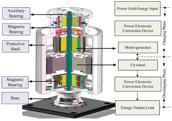
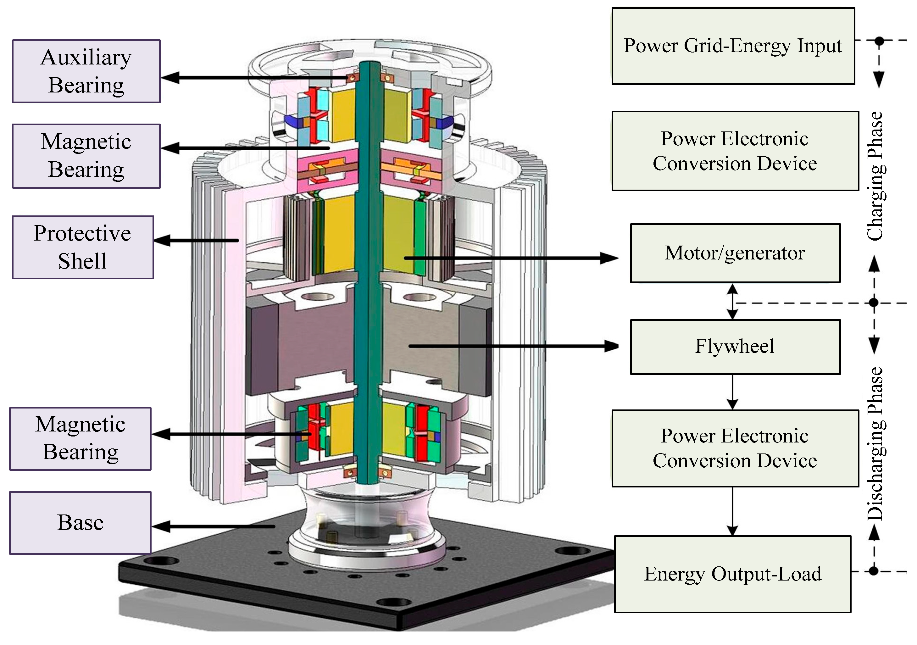
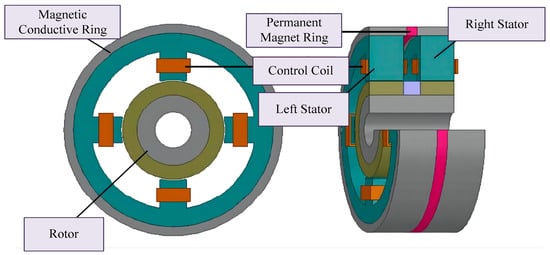
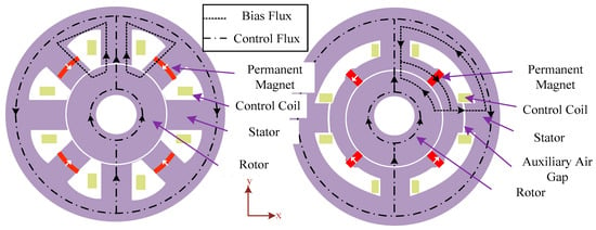
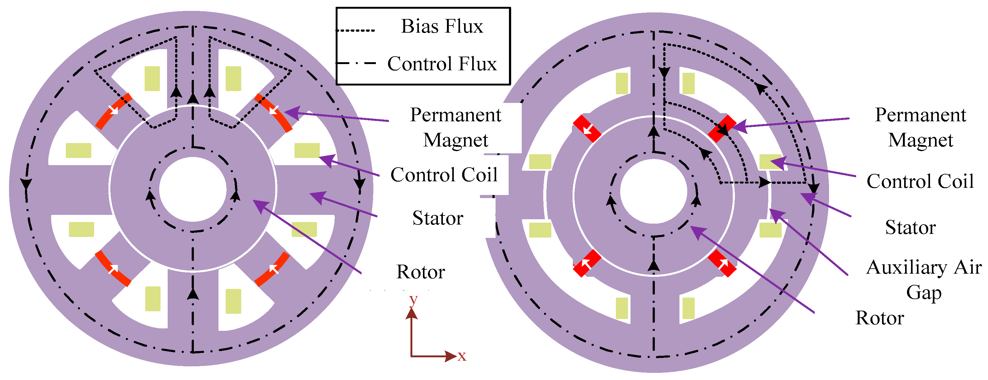
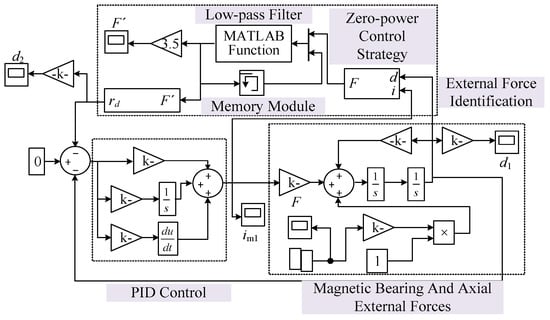
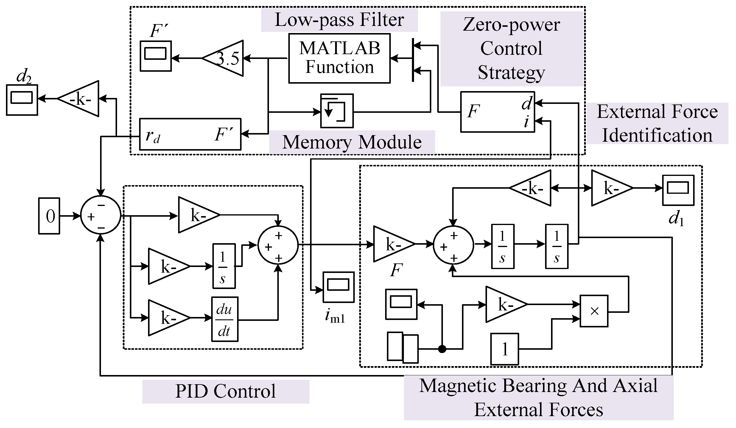
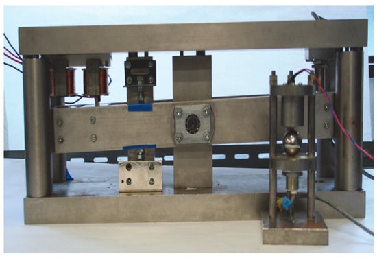
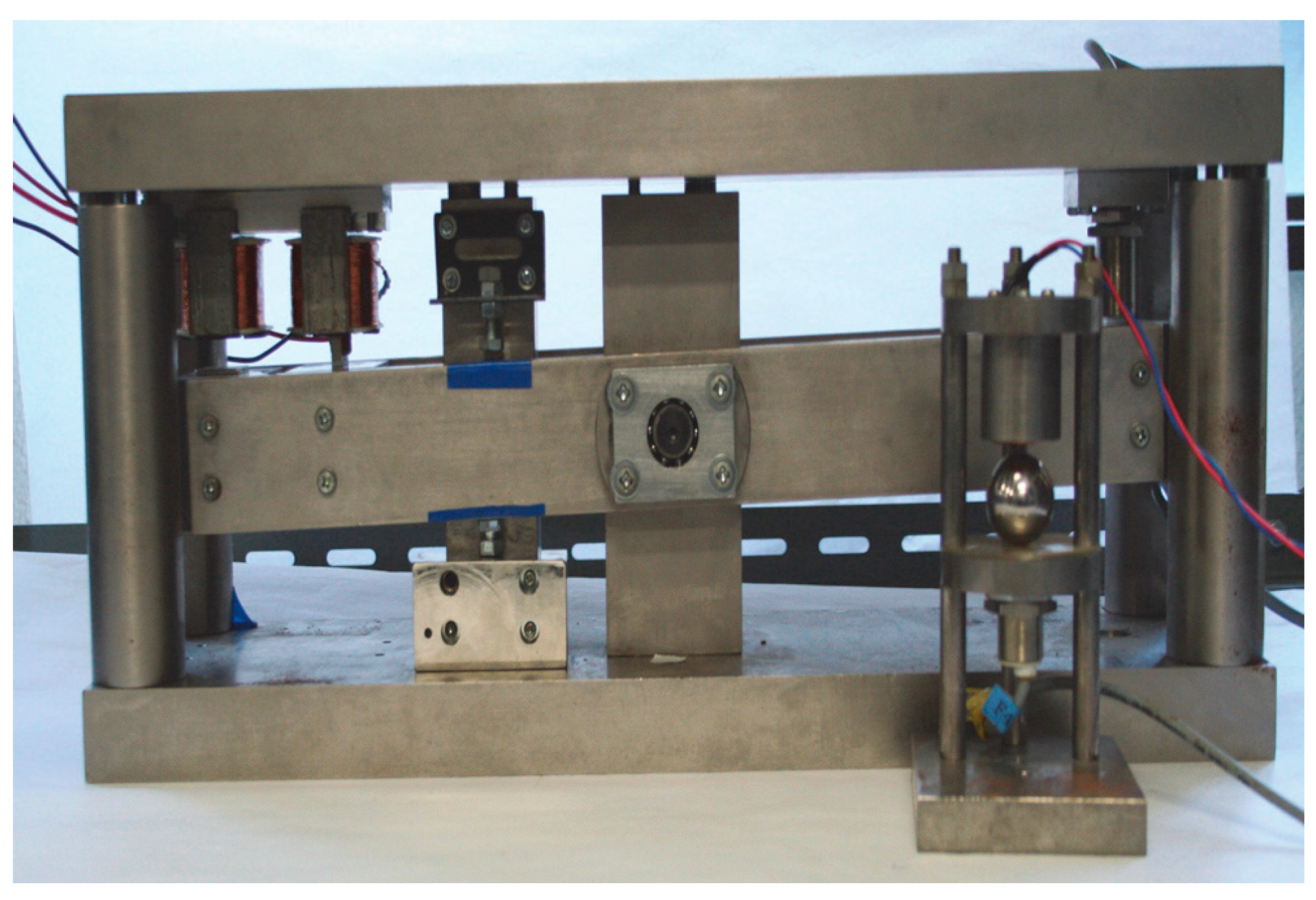
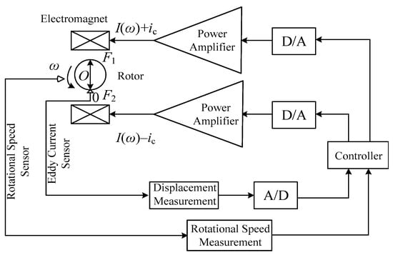
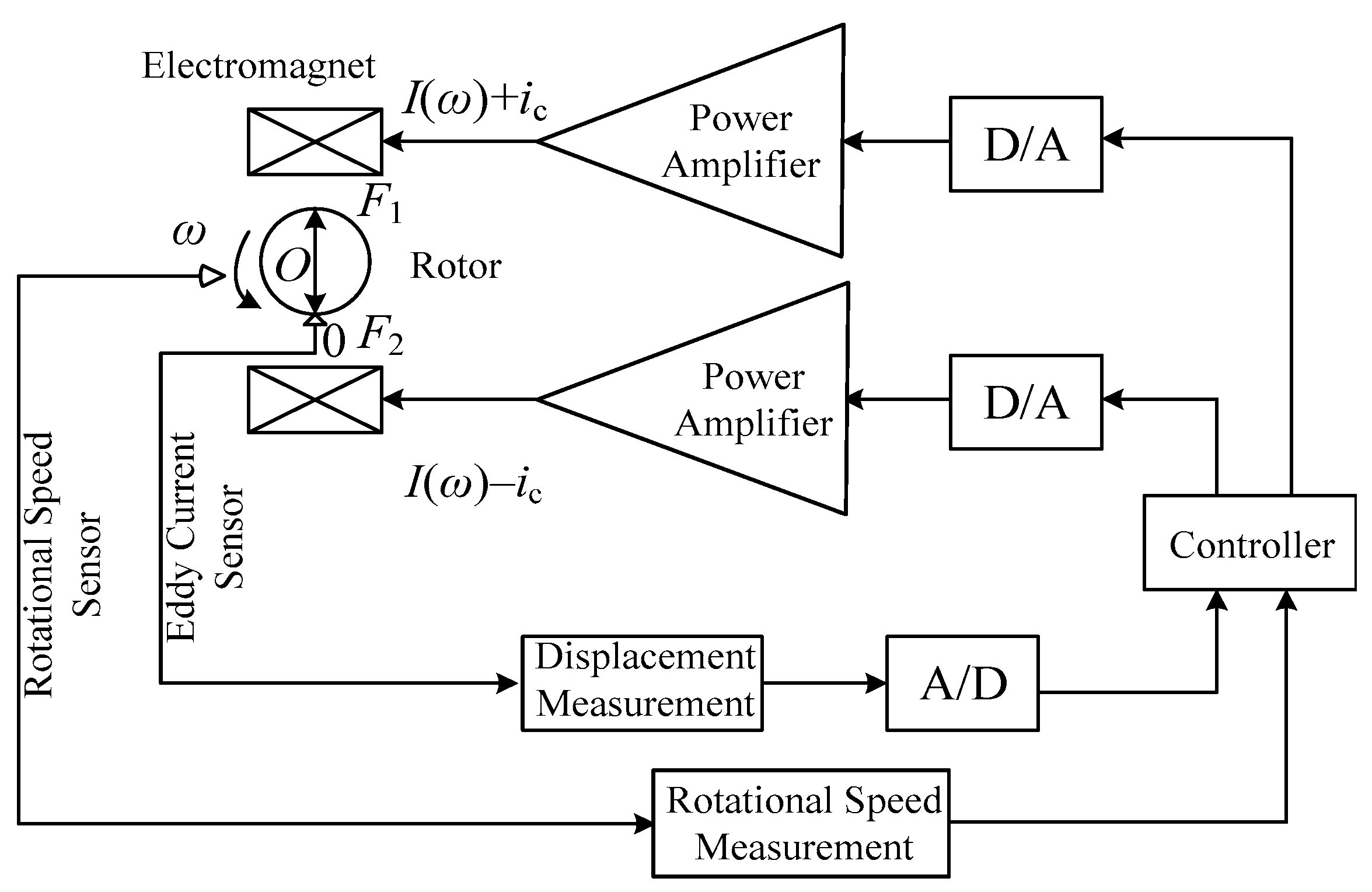
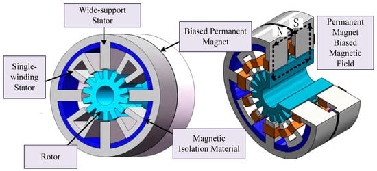
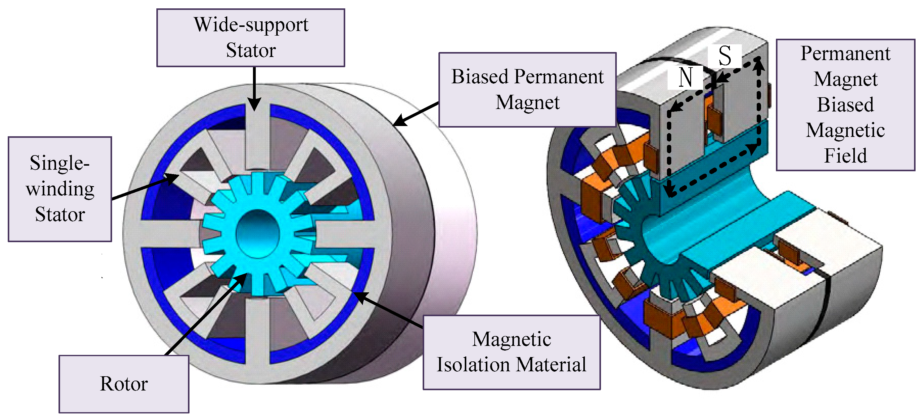
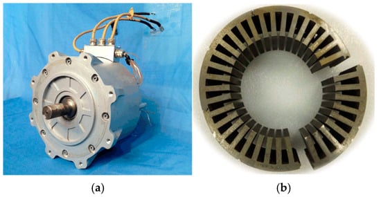
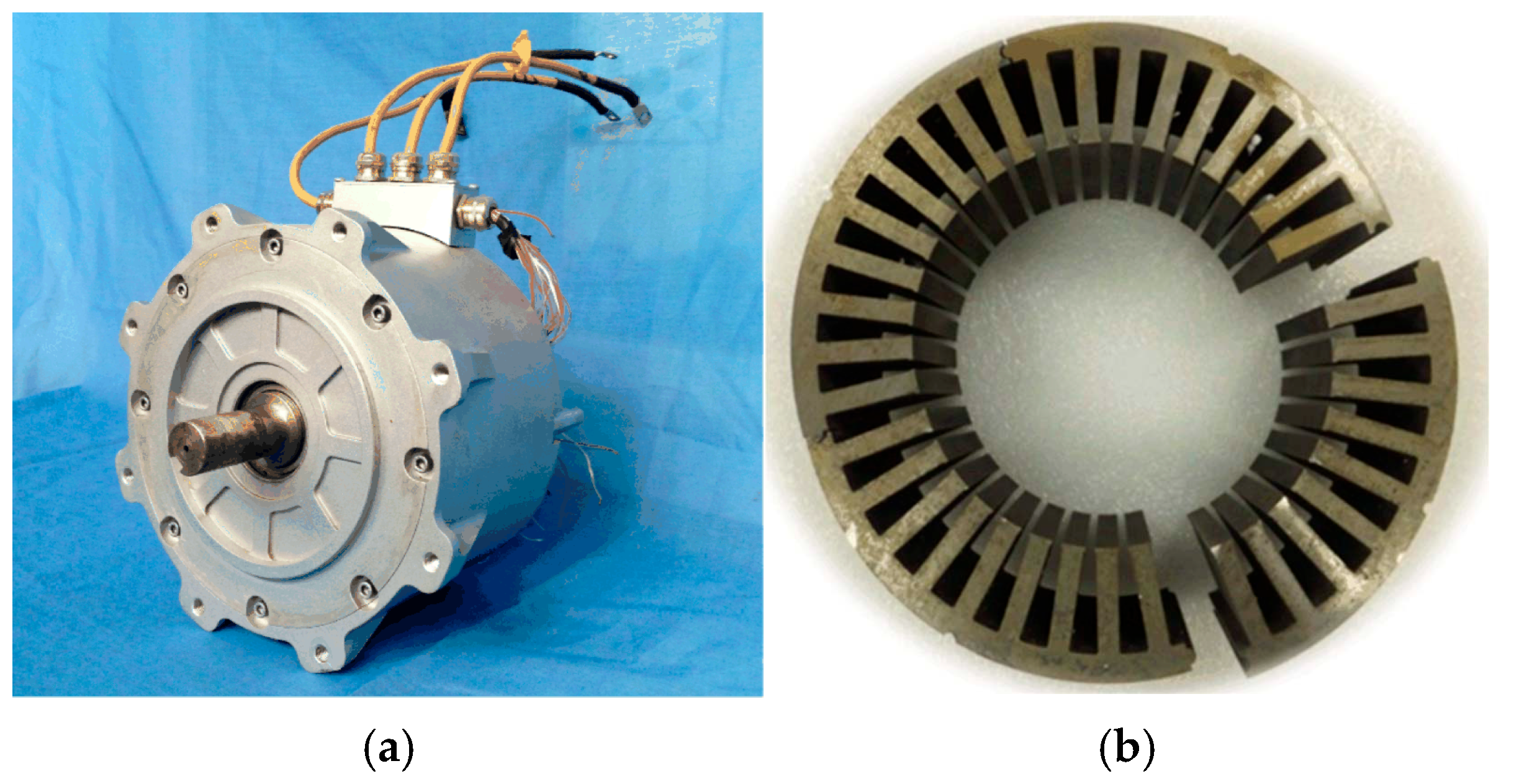

Disclaimer/Publisher’s Note: The statements, opinions and data contained in all publications are solely those of the individual author(s) and contributor(s) and not of MDPI and/or the editor(s). MDPI and/or the editor(s) disclaim responsibility for any injury to people or property resulting from any ideas, methods, instructions or products referred to in the content. |
© 2026 by the authors. Licensee MDPI, Basel, Switzerland. This article is an open access article distributed under the terms and conditions of the Creative Commons Attribution (CC BY) license.