


Abstract
Long-distance pulling of submarine cables inside horizontal directional drilling (HDD) steel casings is often limited by high interfacial resistance, rapid pulling-force accumulation, and poor adaptability to muddy-sandy environments. In addition, conventional outward-extending roller devices are relatively bulky, which increases the required casing diameter and reaming size. To address these issues, this study proposes a compact ball-frame and tensioned steel cable series drag-reduction device. An 18 m local full-scale pulling test system was established using an actual engineering submarine cable, a practical-scale steel casing, and full-scale drag-reduction devices. The effects of pipe curvature, device spacing, terminal reaction force, and in-casing medium conditions on the equivalent friction coefficient were investigated. The results show that the equivalent friction coefficient of the submarine cable–steel casing system is maintained at 0.25–0.36 under most test conditions, which is significantly lower than the commonly adopted value of 0.55 for direct contact. Based on the experimentally identified parameters, a simplified assessment model for ultimate pulling length was established for construction scheme comparison and preliminary capacity estimation. The results indicate that, with the implementation of the tensioned steel cable series system, the ultimate pulling length increases from 431/696 m for direct pulling to 954/1424 m. These results provide valuable technical references for drag-reduction scheme selection and preliminary construction-capacity assessment in HDD landfall sections.
1. Introduction
With the rapid development of offshore wind power, offshore oil and gas exploitation, and island power supply projects, the safe and efficient installation of submarine cable landfall sections has become a key issue in marine energy infrastructure construction. Compared with open-cut methods, horizontal directional drilling (HDD) can effectively reduce disturbance to shoreline landforms, beach ecology, and existing structures, and thus has been widely adopted for submarine cable landfall crossings [1,2,3,4,5,6,7,8,9]. However, unlike conventional HDD pullback operations for onshore pipelines, submarine cables are characterized by high flexibility, large unit weight, and strict requirements on abrasion resistance of the outer sheath and bending control. During pulling within steel casings, their mechanical response is influenced not only by path curvature, buoyancy effects, and terminal reaction forces, but also, to a large extent, by the continuous accumulation of friction at the cable–casing interface [10,11,12,13,14].
The installation of submarine cables in HDD steel casings generally involves drilling guidance, reaming, steel-pipe retrieval, and final cable pullback. Existing studies on HDD construction mechanics have made substantial progress in pullback force prediction, bore-path optimization, drilling fluid effects, and pipe–soil interaction mechanisms. Baumert et al. [6,7], Cheng and Polak [5], Yang et al. [8], Rabiei et al. [9], Cai and Polak [10], Guo et al. [11,12], and Yan et al. [4] have systematically investigated HDD pullback loads using empirical, theoretical, dynamic, and review-based approaches. Xu et al. [15], Lu et al. [13,14], Patino-Ramirez et al. [16], Kong et al. [17], and Faghih et al. [18] further improved the prediction accuracy of pulling loads through numerical simulation, machine learning, contact-state identification, and field monitoring. These studies provide an important basis for HDD engineering design; however, their primary focus has been on steel pipes, polyethylene pipes, or drill-string systems, while dedicated studies on submarine cable pulling within HDD steel casings remain extremely limited.
In the field of submarine cable installation, existing research has mainly concentrated on free-span behavior, dynamic responses in the splash zone, vessel–cable coupled behavior during laying, and local mechanical responses of the cable body itself. Studies by Yoshizawa and Yabuta [19], Prpić-Oršić and Nabergoj [20], Zhang et al. [21], Chang and Chen [22], Kuang et al. [23], and Qian et al. [24] indicate that cable tension is closely related to the entry angle, laying speed, wave–current environment, burial depth, and cable self-weight. Further studies by Mamatsopoulos et al. [25], Fang et al. [26,27,28], Ringsberg et al. [29], and Cerik and Huang [30] have shown that, with increasing cable size, stiffness, and landfall length, the conflict between installation tension control, local mechanical response, and allowable tensile capacity becomes increasingly prominent. Nevertheless, these studies mainly address open-water installation, general HDD pullback processes, or local mechanical behavior of the cable itself, whereas limited attention has been paid to rolling drag reduction in confined steel casings, force transmission among connected devices, and adaptability to muddy-sandy environments.
From an engineering perspective, currently used roller brackets, roller boxes, or centralizer-type devices can transform local sliding friction into rolling friction to some extent; however, they generally rely on externally protruding rollers, resulting in a relatively large structural envelope and consequently imposing higher requirements on the inner diameter of the steel casing. Existing HDD pullback and submarine cable landfall studies generally indicate that, as crossing distance increases, casing size, interface friction, and construction equipment capacity become strongly coupled [17,18,24,31,32,33,34]. This means that when the cable diameter reaches 250 mm, the use of conventional protruding roller supports often necessitates a significant increase in casing diameter. A larger casing and reaming diameter, in turn, increases reaming workload, drilling fluid consumption, waste slurry disposal, and site and equipment requirements. Therefore, for HDD-based submarine cable landfall installation, there is a clear engineering need to develop a drag-reduction device that combines rolling support with a compact structural envelope.
In addition to the issue of structural size, existing devices commonly suffer from two further limitations. First, most roller-support units work independently and lack an axial force-transmission system connecting adjacent units. As a result, the pulling force is still primarily borne by local devices and the cable armor layer, which is unfavorable for segmented load transfer and stress equalization under long-distance pulling conditions. Second, the actual environment inside HDD steel casings often involves the coexistence of water, drilling slurry, and sand. Conventional wheel-based supports are more likely to experience wheel sinkage or rolling failure under sediment accumulation, whereas dedicated designs for sand discharge, pressure relief, and cross-sectional streamlining have rarely been reported [25,27,28,29,30,35]. Therefore, achieving low friction, distributed force transfer, and adaptability to muddy-sandy environments within the limited space of a steel casing remains a key technical challenge for this type of system.
To address the above research gaps, this study focuses on the long-distance pulling of submarine cables inside HDD steel casings and proposes a ball-frame and tensioned steel cable series system. The research is carried out in three aspects. Firstly, based on the compact ball-frame structure, longitudinal tensioned steel cable connection, and water-passing/sand-discharging configuration, the novelty of the proposed device relative to conventional roller-based schemes is systematically clarified. Secondly, local full-scale pulling tests are conducted to obtain equivalent friction coefficients under varying curvature, device spacing, terminal reaction force, and in-casing conditions. Thirdly, a simplified assessment method for the ultimate pulling length is established using experimentally determined parameters, and the contribution of the device and the series system to improving installation capability is analyzed. This study aims to provide a quantitative technical basis for process design, casing size selection, and construction risk control for submarine cable landfall sections installed by HDD.
2. Mechanics of Submarine Cable Pulling and Drag-Reduction Device
2.1. Mechanics of Submarine Cable Pulling
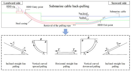
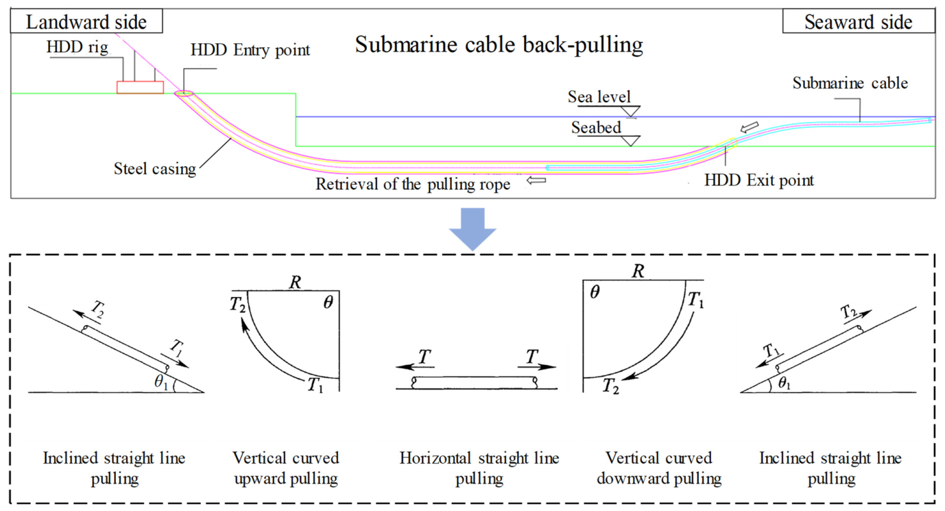
As shown in Figure 1, the final and most critical stage of submarine cable installation by horizontal directional drilling (HDD) is to pull the cable back through the steel casing to its designated position. In general, the cable crossing path includes horizontal straight sections, inclined straight sections, and curved sections. Although the mechanical state varies among these path segments, the pulling force in each case is strongly affected by interfacial friction. Therefore, a differential cable element in each path segment can be taken as the analysis object, and the corresponding pulling-force expressions can be derived based on force equilibrium.
Figure 1.
Schematic illustration of submarine cable pullback and pulling force calculation models for different sections of the crossing path.
Horizontal straight line pulling:
Inclined straight line downward pulling:
Inclined straight line upward pulling:
Vertical curved downward pulling:
Vertical curved upward pulling:
where μ is the friction coefficient; W is the unit weight of the cable (N/m); L is the cable length (m); and R is the cable bending radius (m). θ and θ1 denote the central angle of the curved segment (rad) and the inclination angle of the straight inclined segment (rad), respectively. The pulling-force calculation in Equations (1)–(3) is consistent with the formulas given in Appendix A of the Technical Code for the Design of Urban Power Cables (DL/T 5221-2016) [36], but there is a certain difference in the expression for the pulling force in the vertical bending section. The detailed derivation of the above pulling-force expressions is provided in Appendix A.
Equation (1) shows that the pulling force mainly originates from frictional resistance associated with the cable weight and is further amplified in curved sections because of the additional normal force generated by pipeline curvature. In practice, local settlement, eccentric contact, and unstable rolling or sliding in water- and slurry-containing environments may further increase the effective resistance during pullback. Therefore, the friction coefficient at the cable–casing interface is not only a basic calculation parameter but also one of the most critical factors governing constructability in long-distance HDD installation.
It should be noted that Equation (1) is adopted here as a segmental engineering calculation formula rather than a full-field mechanical model. The local resistance of a straight or curved segment is related to the adopted friction coefficient, whereas the total pulling force along the entire HDD route is obtained through section-by-section accumulation.
2.2. Ball-Frame and Tensioned Steel Cable Series Drag-Reduction Device
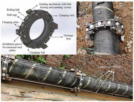
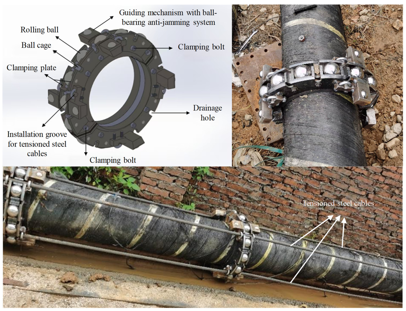
In the long-distance HDD pulling construction of submarine cables, the interface friction coefficient between the cable and its steel casing is a key parameter determining the growth rate of the pulling force and the ultimate pulling length. To mitigate sliding friction during the cable’s passage through the steel casing and to transform the contact surface sliding to multi-point rolling support, a ball-frame drag-reduction device is proposed. Its 3D schematic diagram and physical prototype are shown in Figure 2. The drag-reduction device is designed as a clamp-type annular structure, consisting primarily of rolling balls, a ball cage, and side clamping plates, and incorporating guiding components and drainage holes. The split ball-frame clamp is secured to the outer surface of the submarine cable using high-strength bolts, forming an individual drag-reduction unit. These units are interconnected by high-strength tensioned steel cables continuously arranged along the cable axis, thereby establishing a multi-point series drag-reduction system.
Figure 2.
3D schematic diagram and physical prototype of the ball-frame drag-reduction device.
The drag-reduction device proposed in this study is not a conventional outward-extending roller support but rather a compact ball-frame and tensioned steel cable series system specifically designed for submarine cable pulling inside HDD steel casings. Its key innovations are reflected in the following three aspects.
(1) Compact rolling-support structure based on circumferential balls.
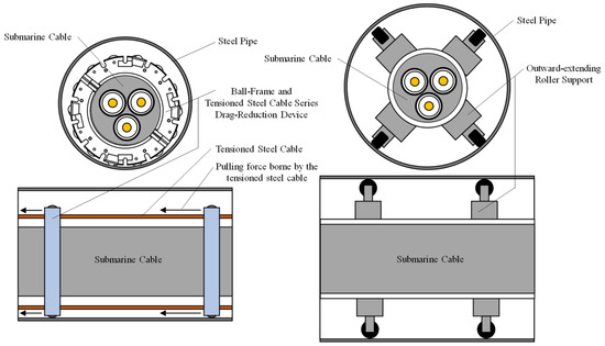
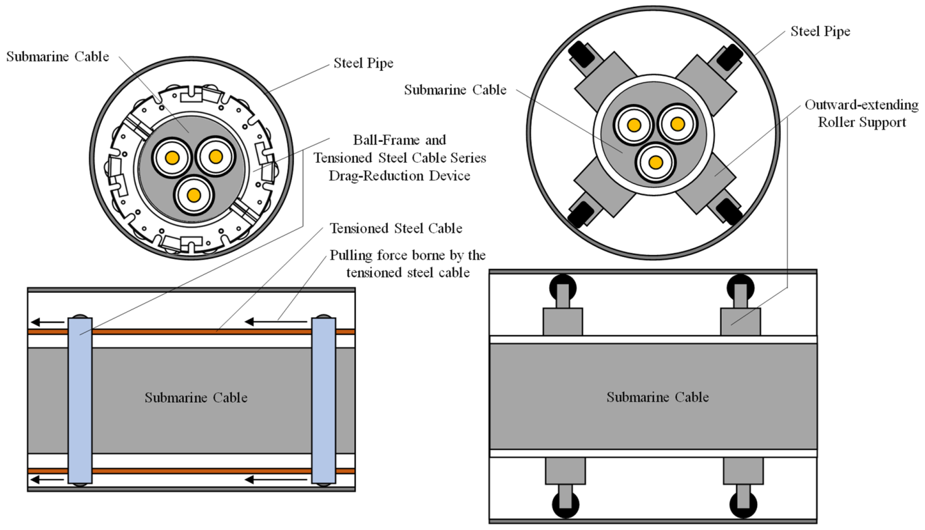
As shown in Figure 3, traditional roller-type supports generally adopt outward-extending roller assemblies with relatively large roller shafts and support heights. Although such configurations can reduce local friction, they also substantially increase the overall envelope size of the device, thereby requiring a larger steel casing diameter, a larger reaming diameter, and consequently higher construction costs. In contrast, the proposed device employs a circumferential ball-frame support configuration, in which the rolling elements are embedded within the frame and only the necessary portion of each ball is exposed. This design ensures rolling contact while significantly reducing the radial dimension of the device. For a submarine cable with an outer diameter of 250 mm, the full-scale tests in this study successfully operated within a steel casing of 460 mm inner diameter, representing a reduction of approximately 23.3% compared with the conventional 600 mm baseline. Based on the cross-sectional area of a circular bore, reducing the casing diameter from 600 mm to 460 mm corresponds to an approximately 41.2% decrease in reaming area. Therefore, the value of the proposed device lies not only in converting sliding friction into rolling friction but also in mitigating the casing-enlargement effect caused by the drag-reduction device itself through structural compactness.
Figure 3.
Schematic comparison of the proposed drag-reduction device and a conventional outward-extending roller support.
(2) Longitudinal force transmission through a tensioned steel cable series connection.
Existing roller-type support devices mostly operate as discrete units, with little or no active longitudinal coordination between adjacent supports. Under long-distance pulling conditions, this may lead to excessive local loading on the submarine cable, instability in the posture of individual devices, and local sticking or jamming. In the present design, four longitudinal tensioned steel cables are arranged between adjacent drag-reduction units, connecting them into a chain-like series system. With this configuration, the pulling force is no longer borne solely by the local armor layer of the cable and individual support units but is instead transferred in a segmented manner through a composite load path consisting of the cable–drag-reduction unit–tensioned steel cable system. This improves the uniformity of axial force transmission and reduces peak tension as well as local stress concentration. This feature clearly distinguishes the proposed device from single-ring supports or conventional roller cradles and represents an important innovation applicable to long-distance submarine cable pulling.
(3) Sand-discharge and flow-adaptive capability for muddy-sandy environments.
Water, drilling slurry, and fine sand commonly coexist inside HDD steel casings. Owing to their narrow wheel width, concentrated contact pressure, and sensitivity to bottom sediment deposition, conventional wheel-based devices are more prone to sinking into the muddy-sandy layer, leading to rolling failure in a manner analogous to vehicle bogging. In contrast, the proposed device, together with the submarine cable, forms an approximately circular outer profile, which can flatten and displace sediment accumulated at the bottom of the casing during the pulling process. Meanwhile, water-passing holes are provided in the side walls of the frame to release local pore-water pressure and to provide pathways for fine-particle migration, thereby reducing sediment buildup ahead of the device and lowering the risk of ball blockage. Therefore, the proposed system is not limited to dry steel casing conditions but is specifically adapted to the muddy-sandy environments frequently encountered in practical HDD-based submarine cable installation. This environmental adaptability constitutes another important aspect of the novelty of the proposed device.
Therefore, compared with conventional roller centralizers or roller-box-type devices, the innovation of the proposed system lies not in the presence of rolling elements alone, but in the coupled realization of compact ball support, longitudinal series load transfer, and muddy-sandy environment adaptability. Through this coupling, the device achieves the integration of drag reduction, reduced casing size demand, and enhanced performance in complex in-casing environments, making it more suitable for long-distance submarine cable pulling in HDD landfall applications.
3. Determination and Analysis of Friction Coefficients from Pulling Experiments
To verify the drag-reduction performance of the proposed device under submarine cable pulling conditions inside HDD steel casings and to provide reliable input parameters for the subsequent simplified assessment of ultimate pulling length, a local full-scale pulling test system was established in this study. The equivalent friction characteristics between the drag-reduction device and the steel casing were systematically investigated under different pipe curvatures, device spacings, terminal reaction modes, and in-casing environments. It should be noted that the primary objective of the present experiments is not to directly reproduce the full pullback process of kilometer-scale HDD submarine cable installation in the laboratory, but rather to identify the most critical input parameter for long-distance pulling assessment, namely, the equivalent friction coefficient of the drag-reduction device–steel casing system. For this parameter, representativeness depends mainly on whether the contact materials, structural scales, boundary constraints, curvature conditions, and in-casing environments are consistent with those encountered in practice, rather than on the total test length alone. On this basis, the experiments were conducted using an actual engineering submarine cable, full-scale drag-reduction devices, and a steel casing of practical dimensions so as to preserve the major controlling factors involved in cable pulling inside HDD steel casings as realistically as possible.
3.1. Experiment System and Representativeness
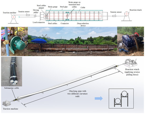
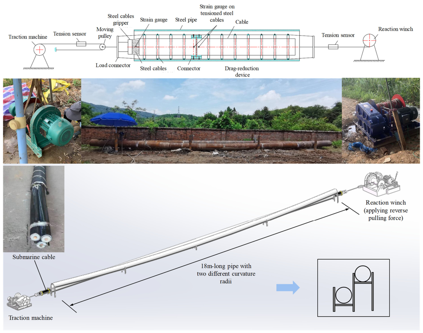
As shown in Figure 4, a submarine cable pulling experiment system with a total length of 18 m was established, consisting mainly of the test pipe section, submarine cable, drag-reduction devices, pulling steel rope, traction machine, reaction winch, tension sensors, and a data acquisition system. The submarine cable adopted in the experiment was of actual engineering specification, with a length of 16.23 m, an outer diameter of 250 mm, and a linear density of 114 kg/m. The steel casing used in the experiment had an outer diameter of 480 mm and an inner diameter of 460 mm and included both straight and curved pipe sections. The curved section had a curvature radius of 213 m, approximately 500 D, which can reasonably simulate the gentle curved segments commonly encountered in HDD crossing paths. A traction machine and a reaction winch were arranged at the two ends of the experiment pipe, respectively, and tension sensors were installed to continuously monitor the pulling force at the pulling end and the reaction force at the trailing end.
Figure 4.
Schematic diagram and physical setup of the submarine cable pulling experiment.
Compared with scaled model testing, the present experimental setup adopted full-scale configurations in terms of submarine cable diameter, steel casing dimensions, device structure, and contact relationship. The purpose was to reproduce as faithfully as possible the contact state, rolling behavior, and mechanical characteristics of the drag-reduction device within the steel casing. It should be emphasized that although the pulling-force evolution in long-distance HDD submarine cable installation is indeed closely related to total pulling length, the validity of the present experiments does not rely on using an 18 m test section to directly simulate a field installation over several hundred meters or even kilometers. Instead, the key objective is to identify the equivalent interfacial friction parameter of the device-assisted system based on an actual-scale contact configuration. Therefore, the present experiments should be regarded as full-scale parameter-identification tests, whose main role is to characterize the variation in interfacial friction behavior under different operating conditions, rather than to replace field-scale validation.
3.2. Experiment Conditions and Procedures
To cover the major factors influencing practical HDD submarine cable pulling as comprehensively as possible, the experiment conditions were designed from four aspects, namely, pipeline geometry, device arrangement, in-casing condition, and terminal reaction boundary. First, both straight and curved pipe sections were considered to simulate the straight and curved portions of the crossing path, respectively. Second, two installation spacings, 1 m and 2 m, were adopted for the drag-reduction devices in order to evaluate the influence of support density on rolling continuity and interfacial resistance. Third, both dry and sand-slurry environments were considered to simulate two representative conditions inside HDD steel casings, namely, cases without deposition and cases involving mud-sand accumulation. Finally, three terminal reaction modes, namely, disengaged, unloaded, and braking, were introduced at the trailing end to simulate different force boundary conditions corresponding to different pulling stages and different levels of external resistance. As shown in Table 1, the above factors were combined to form 13 representative test cases, each of which was repeated two to three times to improve the stability and representativeness of the results.
Table 1.
Experimental conditions for measuring the friction coefficient of the submarine cable–steel casing interface.
Before each test, the drag-reduction devices were installed on the outer surface of the submarine cable at the prescribed spacing, and adjacent units were connected by high-strength tensioned steel cables. The cable was then placed inside the experiment’s steel casing and connected to the pulling steel rope at the front end. During the experiment, the cable was pulled forward by the traction machine at a relatively stable speed, while the reaction winch at the trailing end was set to disengaged, unloaded, or braking conditions according to the selected experiment case. The experiment system synchronously recorded the pulling force at the pulling end, the reaction force at the trailing end, and the pulling displacement as functions of time. To avoid the influence of start-up transients and unloading effects near the end of pulling on the identification of friction coefficients, only data from the steady pulling stage were used in the subsequent inverse analysis.
3.3. Inverse Determination of Friction Coefficients and Treatment of Uncertainty
During cable pulling, the experiment section at any time t can be regarded as being in a quasi-static force equilibrium state. Based on the relationships among the pulling force, reaction force, gravity, and frictional resistance acting on the cable inside and outside the steel casing, the force equilibrium equation shown in Equation (6) can be established.
where F1 and F2 denote the measured pulling force at the pulling end and the reaction force at the trailing end, respectively; M0 and M1 represent the weights of the cable and drag-reduction devices inside and outside the steel casing; and f0 and f1 denote the equivalent friction coefficients inside and outside the steel casing, respectively. Since F1, F2, and the pulling displacement can be directly obtained from the sensors, while the remaining geometric and weight-related quantities are known, f0 and f1 can be treated as the unknown parameters to be identified.
In the actual calculation, multiple sampling instants were selected from the steady pulling stage of each test case. As shown in Equation (7), the corresponding force equilibrium equations at these sampling instants were assembled into an overdetermined system with respect to f0 and f1, which was then solved using the least-squares method to obtain the equivalent friction coefficients for the corresponding operating condition.
It should be emphasized that the identified f0 does not represent the pure rolling friction coefficient of an individual ball in an idealized sense. Rather, it is an equivalent integrated parameter that comprehensively reflects the combined effects of ball rolling, local sliding, device posture adjustment, guiding-component constraints, mud-sand disturbance, and local contact bias. Therefore, this parameter is more suitable as an engineering input for long-distance submarine cable pulling models than as a fundamental tribological property of a single local contact pair.
To reduce the influence of random errors, each experiment case was repeated two to three times, and the final friction coefficient was taken as the average of the repeated measurements. Since the primary objective of this study is to identify the main controlling factors and establish engineering evaluation parameters, only the mean values are reported in the main text. Further improvement may include the addition of standard deviations or coefficients of variation to enhance the statistical reliability of the results.
3.4. Experimental Results and Mechanism-Based Interpretation of Friction Coefficients
The equivalent friction coefficients between the drag-reduction device and the steel casing obtained using the above inverse procedure are summarized in Table 2. Overall, under most test conditions, f0 falls within the range of 0.25–0.36, which is substantially lower than the sliding friction coefficient of approximately 0.55 [37] typically adopted for direct contact between the submarine cable and the steel casing. This indicates that the proposed drag-reduction device can effectively transform the dominant interfacial contact mode from sliding friction to a composite contact state governed primarily by rolling support, thereby significantly reducing friction accumulation during long-distance pulling.
Table 2.
Friction coefficient f0 between the drag-reduction device and the steel casing under each condition.
From the perspective of path curvature, under dry conditions with a device spacing of 2 m and a disengaged terminal boundary, the friction coefficient increased from 0.253 for the straight pipe to 0.366 for the curved pipe. Under braking conditions, the corresponding friction coefficients for the straight and curved pipes were 0.252 and 0.361, respectively. These results indicate that curved sections significantly increase the equivalent friction level. This can be mainly attributed to the fact that in curved sections, the cable and devices tend to shift toward the outer bend, thereby increasing local normal contact pressure. At the same time, the devices are required to undergo more frequent posture adjustments while passing through the curved trajectory, and some balls may experience local sliding or non-ideal rolling, which results in additional resistance. Therefore, curved sections are consistently the most sensitive segments in terms of pulling-force amplification during HDD pullback of submarine cables, and they should be regarded as the key locations for the design and arrangement of drag-reduction devices.
Regarding device spacing, a smaller spacing does not necessarily result in a lower equivalent friction coefficient. Under straight-pipe sand-slurry conditions, reducing the spacing from 2 m to 1 m did not lead to a stable friction-reduction advantage. Under dry curved-pipe conditions, the 1 m spacing even produced higher friction coefficients than the 2 m spacing in some cases, reaching 0.504 under braking conditions. This phenomenon suggests that although reducing device spacing improves the continuity of rolling support, the increase in the number of devices also introduces stronger chain-like connection constraints and more complicated posture-coordination issues. These effects become particularly significant in curved sections or under high axial reaction forces, where local interference among multiple units and restricted coordinated deformation may offset, or even partially counteract, the friction-reduction benefit brought by denser support. It follows that the arrangement spacing of the drag-reduction devices should be determined by considering not only support continuity but also system-level coordinated deformability and installation convenience, rather than simply pursuing the densest possible layout.
With respect to the in-casing condition, the friction coefficients under sand-slurry environments were generally higher than those under dry conditions, although the increase was not monotonic. For example, under the disengaged condition in the straight pipe with a 2 m spacing, the friction coefficient increased from 0.253 in the dry case to 0.291 in the sand-slurry case; in the curved pipe with a 1 m spacing, it increased from 0.384 to 0.486. These results indicate that the mud-sand medium exerts both lubricating and hindering effects on device motion. On the one hand, water-bearing fine particles may locally form a lubricating layer, thereby reducing friction in some contact regions. On the other hand, bottom deposition, fine-sand accumulation, and slurry disturbance may hinder the free rolling of the balls and increase local resistance. The proposed device, when combined with the submarine cable, forms an approximately circular outer profile, which can flatten and displace bottom sediment during forward movement. Meanwhile, the drainage holes provided in the side wall of the frame can release local hydraulic pressure and provide migration paths for fine particles, thereby alleviating mud-sand accumulation and ball blockage to a certain extent. Therefore, although muddy-sandy environments do increase system resistance, the proposed device still maintains favorable rolling passage capacity in sand-containing media, which indirectly verifies the effectiveness of its targeted adaptation to realistic HDD muddy-sandy conditions.
From the perspective of the terminal reaction mode, the friction coefficients under braking and unloaded conditions were generally higher than those under disengaged conditions, indicating that the contact state between the drag-reduction device and the steel casing changes with increasing axial load level. A higher terminal reaction force implies a stronger overall tensile state of the system, under which the devices are more likely to undergo posture adjustment and local additional pressing under the combined effects of axial tension and local eccentricity, thereby deteriorating the rolling conditions of some balls and leading to an increase in the equivalent friction coefficient. This observation indicates that although the proposed device can significantly reduce interfacial resistance, its drag-reduction performance is still affected by axial load level and contact-state evolution. Therefore, in practical engineering applications, the device arrangement should be optimized in conjunction with pulling-force monitoring.
Overall, the experimental results demonstrate that the proposed drag-reduction device can substantially reduce the interfacial friction between the submarine cable and the steel casing under different path geometries and in-casing conditions. At the same time, the experiments also reveal the complex coupled effects of curvature, device spacing, muddy-sandy environment, and terminal reaction force on the frictional performance of the system, which provides an important basis for further optimization of device structure and arrangement parameters.
3.5. Discussion on Engineering Applicability and Limitations
It should be further noted that the main purpose of the present experiments is to identify the equivalent interfacial friction parameters of the drag-reduction device–steel casing system under different controlling factors and to analyze their variation characteristics, rather than to directly validate the full pullback process of kilometer-scale HDD submarine cable installation. As the pulling length increases, factors encountered in field practice, such as trajectory deviation, casing-wall irregularity, local casing deformation, evolution of mud-sand deposition, construction disturbance, and pulling-speed fluctuation, may further affect the evolution of pulling force. Therefore, the experimental results are more suitable for construction scheme comparison, drag-reduction performance evaluation, and preliminary estimation of pulling capacity rather than for serving as a substitute for field monitoring or full-scale engineering validation.
Nevertheless, the present experiments maintain strong engineering relevance in terms of submarine cable size, steel casing dimensions, drag-reduction device structure, and the coverage of representative operating conditions. Therefore, the identified equivalent friction parameters and their variation trends still possess clear practical value for engineering applications. Future work may combine field pullback monitoring data, longer-distance laboratory tests, or high-fidelity numerical simulations to further calibrate the friction coefficients and applicability range of the present drag-reduction device.
4. Engineering Implementation and Ultimate Pulling Length Simplified Assessment
With the adoption of the proposed ball-frame and tensioned steel cable series system, the basic sequence of submarine cable installation inside HDD steel casings remains unchanged compared with conventional direct pullback. However, the interfacial contact mode, the load-transfer path, and the movement characteristics under a complex in-casing environment are substantially altered. Therefore, it is meaningful to extract the key procedural considerations that govern long-distance pulling capacity from an engineering control perspective and, on this basis, to establish a simplified assessment method for ultimate pulling length that is directly linked to the experimentally identified parameters. Accordingly, the present section integrates the functional role of the drag-reduction procedure, the major control parameters, and the simplified assessment of ultimate pulling length into a unified discussion, thereby strengthening the technical-analysis focus of the manuscript.
4.1. Key Mechanisms and Control Considerations of the Drag-Reduction Procedure
In conventional HDD submarine cable pullback, the cable is predominantly in continuous sliding contact with the steel casing, and the pulling force accumulates rapidly with increasing pulling length. This effect becomes more pronounced in curved sections and muddy-sandy environments, where the coupling between interfacial friction and local normal pressure leads to further amplification of pulling force. After introducing the proposed ball-frame and tensioned steel cable series system, the essential role of the drag-reduction procedure does not lie in changing the preceding stages of pilot drilling, hole enlargement, or steel-casing installation, but rather in modifying the force-transfer mechanism and the in-casing running condition during the final cable pullback stage.
First, the ball-frame drag-reduction device transforms the dominant contact mode between the submarine cable and the steel casing from surface sliding to multi-point rolling support, thereby significantly reducing the accumulation of interfacial resistance per unit cable length. Second, once adjacent drag-reduction units are connected by longitudinal tensioned steel cables, the pulling force is no longer borne primarily by the local armor layer of the cable and individual support units but is transferred in a segmented and coordinated manner through the composite path of the cable–drag-reduction unit–tensioned steel cable system. This helps reduce local stress concentration and fluctuations in peak pulling force. Third, in water-bearing muddy-sandy environments, the combined outer profile of the device and cable becomes approximately circular; together with the drainage holes and guiding components, this geometry can alleviate bottom sediment accumulation and local blockage to some extent during pulling, thereby improving the continuous passage performance of the system in a complex in-casing environment.
Based on these mechanisms, the drag-reduction procedure should be controlled in practice from three main aspects. First, the installation spacing of the drag-reduction devices should be determined by considering path curvature, device configuration, and experimental evidence so as to balance rolling-support continuity and system-level coordinated deformability. Second, reliable fitting between the device and the cable, as well as stable connection of the tensioned steel cables, should be ensured to avoid loosening, misalignment, or abrupt local force concentration during pullback. Third, in curved sections and muddy-sandy environments, pulling-force monitoring and pulling-speed control should be strengthened to prevent abnormal increases in the equivalent friction coefficient caused by local additional pressing or sediment accumulation. Therefore, the essential value of the drag-reduction procedure lies not in the procedural steps themselves, but in the stable realization of rolling drag reduction and series load sharing through appropriate arrangement and parameter control.
4.2. Simplified Assessment Model for Ultimate Pulling Length
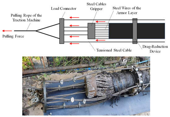
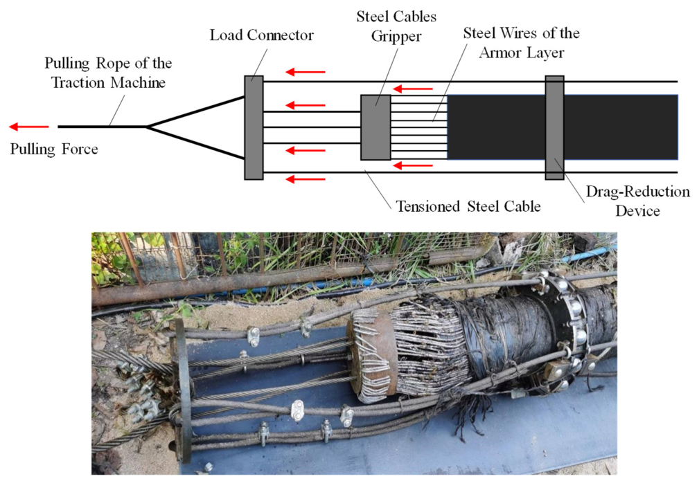
The engineering feasibility of long-distance HDD pullback of submarine cables can ultimately be quantified by whether the allowable tensile capacities of the cable and auxiliary tensioned steel cables are sufficient to overcome the accumulated interfacial resistance under a given device configuration, path condition, and in-casing environment. As shown in Figure 4 and Figure 5, the pulling rope of the traction machine transmits the tensile force through the load connector to the steel wires of the armor layer and the tensioned steel cables connected to the drag-reduction devices. Accordingly, the ultimate pulling length is defined herein as the maximum allowable cable length that can be stably pulled back along a horizontal straight crossing path without exceeding the allowable tensile capacities of the cable armor layer and the tensioned steel cables.
Figure 5.
Schematic illustration of load transfer from the traction machine to the tensioned steel cables and the cable armor layer.
The following assumptions are adopted in the present simplified assessment:
(1) The distributed pulling resistance is mainly generated by the self-weight of the submarine cable, the additional weight of the drag-reduction devices, and the equivalent friction between the system and the inner wall of the steel casing.
(2) After introducing the drag-reduction device, the direct sliding contact between the cable and the casing is replaced by a composite contact state dominated by rolling support, whose overall effect can be represented by the experimentally identified equivalent friction coefficient.
(3) The longitudinal tensioned steel cables share part of the axial pulling load, so that the allowable pulling length depends not only on the allowable tensile capacity of the submarine cable itself but also on the allowable load-carrying capacity of the tensioned steel cables.
(4) Engineering uncertainties, including casing-wall irregularity, local non-ideal rolling of some balls, and construction disturbances, are incorporated through additional influence factors and safety factors.
Based on these assumptions, the force equilibrium equation shown in Equation (8) can be established.
Thus, the following simplified assessment model is adopted for the ultimate pulling length:
where L (m) is the allowable pulling length of the submarine cable; T1max (kN) is the allowable tensile capacity of the cable armor layer; T2max (kN) is the allowable tensile capacity of the tensioned steel cables; K1 and K2 are the safety factors for the submarine cable and the tensioned steel cables, respectively; (kg/m) and (kg/m) are the unit-length weight of the cable and the drag-reduction devices, respectively; is the equivalent friction coefficient of the cable–steel casing interface under the drag-reduction system; is the influence factor associated with the inner-wall irregularity of the steel casing; and is the influence factor representing local rolling failure and additional resistance.
It should be noted that this model is not intended to reproduce every local nonlinear behavior arising during long-distance pullback. Instead, it serves as a simplified and operational framework for construction scheme comparison, drag-reduction performance evaluation, and pulling-capacity estimation, based on the equivalent friction parameters identified from local full-scale experiments. For this reason, it is explicitly referred to here as a simplified assessment model rather than as a high-fidelity full-process field prediction model.
4.3. Parameter Determination and Assessment Scenarios
To ensure an engineering basis for the model parameters, the major input values used in the ultimate pulling length simplified assessment are directly linked to the experimental results and structural design of the proposed system. For conventional direct pulling, the friction coefficient between the submarine cable and the steel casing is taken as 0.55 [37], which is commonly used in engineering practice. For the drag-reduction cases, considering that most experimentally identified equivalent friction coefficients fall within the range of 0.25–0.36 and that higher values are observed in curved sections, under high reaction forces, and in muddy-sandy environments, a conservative representative value of = 0.35 is adopted in the present assessment. The experimental results show that the interfacial friction coefficient can be significantly reduced by the proposed device compared with direct cable–casing contact, while higher coefficients are observed under curved and higher-load conditions; this also supports the need for adopting a conservative parameter in the length assessment.
The allowable tensile capacity of the submarine cable is estimated from the material strength and total cross-sectional area of the armor wires. For the cable used in this study, the armor layer consists of 114 galvanized steel wires with a diameter of 6 mm and a tensile strength of 345 N/mm2, and a safety factor of K1 = 4 is adopted. The allowable tensile capacity of the tensioned steel cables is determined from the selected wire-rope specification and the number of ropes used. In this study, four 5 W × 7–15 mm oil-coated non-rotating steel wire ropes are used, each with a maximum tensile capacity of 137.2 kN, and a safety factor of K2 = 2.5 is adopted. For the drag-reduction cases, with an installation spacing of 2.0 m and an approximate mass of 35 kg for each drag-reduction unit, the unit-length additional weight of the device system is taken as = 17.5 kg/m. For the submarine cable itself, the unit-length weight is taken as 114 kg/m under dry conditions and 70.6 kg/m under submerged conditions, considering buoyancy. To account for additional resistance associated with local casing-wall irregularity and possible non-ideal rolling of some balls, = 1.05 is adopted; = 1.0 is used for direct pulling, and 1.1 is used for the drag-reduction cases.
On this basis, three representative scenarios are comparatively assessed:
(1) Direct pulling of the submarine cable;
(2) Pulling with drag-reduction devices only;
(3) Pulling with both drag-reduction devices and tensioned steel cables.
Both dry and submerged conditions are considered to evaluate the effect of buoyancy-related weight reduction on the ultimate pulling capacity. It should be further noted that, among the above parameters, the material and structural properties of the submarine cable and the tensioned steel cables were determined according to the actual components adopted in this study, whereas K1, K2, α1, and α2 represent one set of representative coefficients selected for the present assessment. These coefficients were kept identical in all comparative calculations so as to ensure a consistent basis for comparison among different pulling schemes. Therefore, the emphasis of the present assessment is placed on the relative effectiveness of different pulling methods, rather than on the uniqueness or optimality of a particular set of coefficient values.
4.4. Assessment Results and Discussion of Ultimate Pulling Length
Using the above parameters, the estimated ultimate pulling lengths under different scenarios are obtained, as summarized in Table 3. The results indicate that under conventional direct pulling conditions, the ultimate pulling lengths of the submarine cable are 431 m and 696 m under dry and submerged conditions, respectively. The difference mainly arises from the buoyancy effect in water, which reduces the effective unit-length weight of the submarine cable and therefore decreases the distributed frictional resistance, resulting in a longer allowable pulling distance.
Table 3.
Estimation of the ultimate pulling length for submarine cables under different conditions.
When only the drag-reduction devices are installed, the ultimate pulling length increases to 534 m and 797 m, respectively, which represents a clear improvement over direct pulling in both environments. This indicates that even without considering the additional load-sharing effect of the tensioned steel cables, the ball-frame drag-reduction device alone can effectively reduce the overall interfacial resistance between the submarine cable and the steel casing by transforming the dominant contact mode from sliding to rolling support. As a result, the accumulation rate of pulling force with increasing distance is slowed down. This finding is consistent with the preceding friction-coefficient experiments, namely, the drag-reduction device improves pulling capacity primarily by reducing the equivalent friction coefficient.
When the longitudinal tensioned steel cables are further introduced, the ultimate pulling lengths increase to 954 m and 1424 m, respectively, which is substantially greater than that achieved by direct pulling. This improvement is not attributable merely to an increase in the total allowable system tensile capacity. More importantly, the series connection provided by the tensioned steel cables improves the force coordination among multiple drag-reduction units, allowing the pulling force to be transferred in a segmented manner through the composite path of the cable–device–steel cable system and thereby reducing the peak axial force borne by the local armor layer of the submarine cable. This result indicates that the engineering advantage of the proposed system does not arise solely from friction reduction but from the combined action of lowering interfacial resistance and improving the force-transfer path.
From an engineering perspective, the calculated results suggest that the ball-frame drag-reduction device provides the first-stage enhancement in ultimate pulling length, whereas the tensioned steel cable series system further amplifies this benefit significantly. This trend is fully consistent with the design philosophy of the proposed system and also agrees with the experimentally observed reduction in friction and improvement in force transmission. At the same time, it should be recognized that the calculated length values are essentially engineering estimates based on experimentally identified friction coefficients and a simplified force model. Their primary value lies in relative comparison among different pulling schemes, evaluation of drag-reduction performance, and preliminary judgment of construction feasibility, rather than in serving as an exact field prediction for a specific project.
4.5. Applicability and Limitations
The proposed model is a simplified assessment method based on measured equivalent friction parameters. Its purpose is to provide a rapid, transparent, and engineering-operational tool for evaluating long-distance HDD pullback capacity of submarine cables, rather than to replace real-time field monitoring or high-fidelity full-process numerical analysis. Moreover, the parameters μ, α1, and α2 all have clear engineering meanings. Among them, μ is derived from local full-scale pulling experiments, while α1 and α2 are introduced to represent difficult-to-quantify uncertainties such as casing-wall irregularity, local non-ideal rolling of some balls, and construction disturbances. Since field data from kilometer-scale projects have not yet been incorporated for direct calibration, the predicted ultimate pulling lengths should be interpreted as conservative assessment results for the scheme-design stage.
In addition, as the pulling length increases, field projects may involve further influencing factors, including bore-path deviation, evolution of local sediment deposition, casing deformation, fluctuations in pulling speed, and long-term rolling wear of the drag-reduction devices. These factors are not explicitly resolved one by one in the present simplified model. Therefore, future work should combine field pullback monitoring, high-fidelity numerical simulation, or longer-distance laboratory testing to further calibrate the model parameters and their range of applicability. Nevertheless, the present method is still capable of capturing the capacity differences among different drag-reduction schemes and provides an engineeringly useful criterion for long-distance pullback in HDD landfall sections of submarine cables.
5. Conclusions
This study investigated the long-distance pulling of submarine cables inside HDD steel casings through drag-reduction device design, local full-scale pulling experiments, and a simplified assessment of ultimate pulling length. The main conclusions are as follows:
(1) The proposed drag-reduction device is a ball-frame and tensioned steel cable series system specifically designed for submarine cable pulling inside HDD steel casings. Its novelty lies in the coupling of compact ball-based support, longitudinal series load transfer, and adaptability to muddy-sandy environments, rather than in the mere use of rolling elements.
(2) The local full-scale pulling experiments show that, after introducing the proposed device, the equivalent friction coefficient of the submarine cable–steel casing system is stabilized at 0.25–0.36 under most test conditions, which is significantly lower than the commonly adopted value of 0.55 for conventional direct contact, demonstrating remarkable drag-reduction capability.
(3) The experimental results further indicate that the equivalent friction coefficient is affected by pipe curvature, device spacing, terminal reaction force, and muddy-sandy in-casing conditions. Among these factors, curved sections and higher reaction-force conditions generally lead to larger friction coefficients, indicating that curved segments remain the key control points for drag-reduction design and pulling control in long-distance applications.
(4) Based on the tensile force equilibrium of submarine cable during pulling in a horizontal straight section and the experimentally identified equivalent friction coefficients, a simplified assessment method for the ultimate pulling length of submarine cables was established. Under the parameter conditions considered in this study, the ultimate pulling length increases from 431 m/696 m for direct pulling to 534 m/797 m with drag-reduction devices only and further to 954 m/1424 m when the tensioned steel cable series system is additionally introduced.
(5) The proposed method is essentially a simplified engineering assessment approach based on local full-scale experimental parameters and is suitable for drag-reduction scheme comparison and preliminary estimation of pulling capacity. For kilometer-scale HDD projects, further calibration against field monitoring data, longer-distance tests, or high-fidelity numerical analyses is still required.
Author Contributions
Conceptualization, R.G.; Methodology, W.G. and W.X.; Formal analysis, Z.H. and W.X.; Investigation, W.G. and H.Q.; Resources, C.L.; Data curation, Z.H. and H.Q.; Writing—original draft, C.L. and L.B.; Writing—review and editing, L.B.; Supervision, R.G.; Project administration, R.G.; Funding acquisition, R.G. All authors have read and agreed to the published version of the manuscript.
Funding
This research received no external funding. The APC was funded by South China University of Technology.
Data Availability Statement
The original contributions presented in this study are included in the article. Further inquiries can be directed to the corresponding authors.
Conflicts of Interest
Authors C.L. and H.Q. were employed by the company Guangxi Power Grid Co., Ltd. Author Z.H. was employed by the company Electric Power Research Institute of Guangxi Power Grid Co., Ltd. Author W.G. was employed by the company Power Grid Construction Branch of Guangxi Power Grid Co., Ltd. Author W.X. was employed by the company China Energy Engineering Group Guangdong Electric Power Design & Research Institute Co., Ltd. The remaining authors declare that the research was conducted in the absence of any commercial or financial relationships that could be construed as a potential conflict of interest.
Appendix A. Derivation of the Pulling-Force Expressions
A typical submarine cable pulling path can be divided into five sections: downward and upward pulling along inclined straight segments, downward and upward pulling along concave curved segments, and pulling along a horizontal straight segment.
(1) Horizontal straight line pulling:
Based on the force equilibrium of a differential cable element, the following expression can be obtained:
where μ is the friction coefficient; W is the unit weight of the cable (N/m); dl is the differential cable length. Integrating the above expression over the pulling length of the horizontal straight line L (m) gives
(2) Inclined straight line downward pulling:
Based on the force equilibrium of a differential cable element, the following expression can be derived:
where θ1 denotes the inclination angle of the straight inclined segment (rad). Integrating the above expression over the pulling length along an inclined straight segment L gives
(3) Inclined straight line upward pulling:
Similarly, based on the force equilibrium of a differential cable element, the following expression can be obtained:
Integrating the above expression over the pulling length L gives
(4) Vertical curved downward pulling:
Consider a differential cable element on a curved segment, with the corresponding central angle and its increment denoted by φ and dφ, respectively. The axial tensions at the two ends of the curved element are T(φ) and T(φ + dφ). Within the curved section, the normal force acting on the cable element arises from both the normal component of the cable self-weight and the normal component induced by bending, which can be expressed as:
where R is the cable bending radius (m). According to the tangential force equilibrium of the differential curved element, the following equation can be obtained:
This equation can be rearranged into the following first-order linear nonhomogeneous ordinary differential equation:
Solving the above equation yields:
When φ = 0, T = T1. Substituting this boundary condition into the above expression gives:
(5) Vertical curved upward pulling:
For upward pulling in the curved section, a similar derivation procedure leads to:
By solving the above first-order linear non-homogeneous ordinary differential equation and applying the same boundary condition, the following expression can be obtained:
References
- Black, S.; Cable, B.; Fredrickson, B.; Warren, D. Horizontal Directional Drilling Cable Shorelanding at San Nicolas Island, California. In Proceedings of the OCEANS’04 MTS/IEEE Techno-Ocean’04 Conference, Kobe, Japan, 9–12 November 2004; IEEE: New York, NY, USA, 2004; pp. 2104–2111. [Google Scholar]
- Earle, B.; Rezutko, J. Novel installation of a 138 kV pipe-type cable system under water using horizontal directional drilling. In Proceedings of the IEEE/PES Transmission & Distribution Conference & Exposition, Chicago, IL, USA, 14–17 April 2014; IEEE: New York, NY, USA, 2014; pp. 1–5. [Google Scholar]
- Ian, G.; Stocker, S. Portland General Electric’s 115 kV XLPE cable transmission line across the Willamette River. In Proceedings of the 2018 IEEE Power & Energy Society General Meeting (PESGM), Portland, OR, USA, 5–10 August 2018; IEEE: New York, NY, USA, 2018; pp. 1–4. [Google Scholar]
- Yan, X.; Ariaratnam, S.T.; Dong, S.; Zeng, C. Horizontal directional drilling: State-of-the-art review of theory and applications. Tunn. Undergr. Space Technol. 2018, 72, 162–173. [Google Scholar] [CrossRef] [Scilit]
- Cheng, E.; Polak, M.A. Theoretical model for calculating pulling loads for pipes in horizontal directional drilling. Tunn. Undergr. Space Technol. 2007, 22, 633–643. [Google Scholar] [CrossRef] [Scilit]
- Baumert, M.E.; Allouche, E.N. Methods for estimating pipe pullback loads for horizontal directional drilling (HDD) crossings. J. Infrastruct. Syst. 2002, 8, 12–19. [Google Scholar] [CrossRef] [Scilit]
- Baumert, M.E.; Allouche, E.N.; Moore, I.D. Drilling fluid considerations in design of engineered horizontal directional drilling installations. Int. J. Geomech. 2005, 5, 339–349. [Google Scholar] [CrossRef] [Scilit]
- Yang, C.J.; Zhu, W.D.; Zhang, W.H.; Zhu, X.H.; Ren, G.X. Determination of pipe pullback loads in horizontal directional drilling using an advanced computational dynamic model. J. Eng. Mech. 2014, 140, 04014060. [Google Scholar] [CrossRef] [Scilit]
- Rabiei, M.; Yi, Y.; Bayat, A.; Moore, I.D. General method for pullback force estimation for polyethylene pipes in horizontal directional drilling. J. Pipeline Syst. Eng. Pract. 2016, 7, 04016004. [Google Scholar] [CrossRef] [Scilit]
- Cai, L.; Xu, G.; Polak, M.A.; Knight, M. Horizontal directional drilling pulling forces prediction methods: A critical review. Tunn. Undergr. Space Technol. 2017, 69, 85–93. [Google Scholar] [CrossRef] [Scilit]
- Guo, Z.; Liang, Z. Analysis of the pipeline pull-back load for horizontal directional drilling. KSCE J. Civ. Eng. 2018, 22, 5133–5142. [Google Scholar] [CrossRef] [Scilit]
- Guo, Z.; Xie, S.; Ren, L.; Dong, C.; Gong, Y. Pipeline pull-back load analysis by continuous beam theory. KSCE J. Civ. Eng. 2020, 24, 1307–1317. [Google Scholar] [CrossRef] [Scilit]
- Lu, H.; Matthews, J.C.; Azimi, M.; Iseley, T. Near real-time HDD pullback force prediction model based on improved radial basis function neural networks. J. Pipeline Syst. Eng. Pract. 2020, 11, 04020042. [Google Scholar] [CrossRef] [Scilit]
- Lu, H.; Iseley, T.; Matthews, J.C.; Liao, W. Hybrid machine learning for pullback force forecasting during horizontal directional drilling. Autom. Constr. 2021, 129, 103810. [Google Scholar] [CrossRef] [Scilit]
- Xu, G.; Cai, L.; Ji, R.; Wang, Z. Numerical simulation of pipe-soil interaction during pulling back phase in horizontal directional drilling installations. Tunn. Undergr. Space Technol. 2018, 76, 194–201. [Google Scholar] [CrossRef] [Scilit]
- Patino-Ramirez, F.; Layhee, C.; Arson, C. Horizontal directional drilling (HDD) alignment optimization using ant colony optimization. Tunn. Undergr. Space Technol. 2020, 103, 103450. [Google Scholar] [CrossRef] [Scilit]
- Kong, L.; Wang, Y.; Wang, Z. Rig load prediction model in horizontal directional drilling within water-rich unstable strata. KSCE J. Civ. Eng. 2022, 26, 556–568. [Google Scholar] [CrossRef] [Scilit]
- Faghih, A.; Goerz, B.; Bayat, A. Accuracy of pull force estimation for steel pipe installation in horizontal directional drilling: Review of 200 Case Studies. J. Pipeline Syst. Eng. Pract. 2022, 13, 04022021. [Google Scholar] [CrossRef] [Scilit]
- Yoshizawa, N.; Yabuta, T. Study on submarine cable tension during laying. IEEE J. Ocean. Eng. 1983, 8, 293–299. [Google Scholar] [CrossRef] [Scilit]
- Prpić-Oršić, J.; Nabergoj, R. Nonlinear dynamics of an elastic cable during laying operations in rough sea. Appl. Ocean. Res. 2005, 27, 255–264. [Google Scholar] [CrossRef] [Scilit]
- Zhang, D.; Bai, Y.; Zhao, W.; Zhu, K. Dynamic analysis of submarine cable during the process of laying back to the seabed. Ships Offshore Struct. 2020, 15, 153–161. [Google Scholar] [CrossRef] [Scilit]
- Chang, H.C.; Chen, B.F. Mechanical behavior of submarine cable under coupled tension, torsion and compressive loads. Ocean. Eng. 2019, 189, 106272. [Google Scholar] [CrossRef] [Scilit]
- Kuang, J.; Chen, G.; Yuan, Z.; Qi, X.; Yu, Q.; Liu, Z. Dynamic interactions of a cable-laying vessel with a submarine cable during its landing process. J. Mar. Sci. Eng. 2022, 10, 774. [Google Scholar] [CrossRef] [Scilit]
- Qian, G.; Kang, W.; Cong, Y.; Liu, Z. A numerical study on the pullback process of a submarine cable based on trenchless directional drilling technology. Water 2025, 17, 1517. [Google Scholar] [CrossRef] [Scilit]
- Mamatsopoulos, V.A.; Michailides, C.; Theotokoglou, E.E.; Onoufriou, T. Critical water depth and installation curves for submarine cable deployment process. J. Mar. Sci. Eng. 2020, 8, 838. [Google Scholar] [CrossRef] [Scilit]
- Fang, P.; Jiang, X.; Hopman, H.; Bai, Y. Mechanical responses of submarine power cables subject to axisymmetric loadings. Ocean. Eng. 2021, 239, 109847. [Google Scholar] [CrossRef] [Scilit]
- Fang, P.; Li, X.; Jiang, X.; Hopman, H.; Bai, Y. Methods for the local mechanical analysis of submarine power cables: A systematic literature review. Mar. Struct. 2025, 101, 103763. [Google Scholar] [CrossRef] [Scilit]
- Fang, P.; Li, X.; Jiang, X.; Hopman, H.; Bai, Y. Bending study of submarine power cables based on a repeated unit cell model. Eng. Struct. 2023, 293, 116606. [Google Scholar] [CrossRef] [Scilit]
- Ringsberg, J.W.; Dieng, L.; Li, Z.; Hagman, I. Characterization of the mechanical properties of low stiffness marine power cables through tension, bending, torsion, and fatigue testing. J. Mar. Sci. Eng. 2023, 11, 1791. [Google Scholar] [CrossRef] [Scilit]
- Cerik, B.C.; Huang, L. Recent advances in mechanical analysis and design of dynamic power cables for floating offshore wind turbines. Ocean. Eng. 2024, 311, 118810. [Google Scholar] [CrossRef] [Scilit]
- Polak, M.A.; Lasheen, A. Mechanical modelling for pipes in horizontal directional drilling. Tunn. Undergr. Space Technol. 2001, 16, 47–55. [Google Scholar] [CrossRef] [Scilit]
- Gelinas, M.; Polak, M.A.; McKim, R. Field tests on HDPE pipes installed using horizontal directional drilling. J. Infrastruct. Syst. 2000, 6, 130–137. [Google Scholar] [CrossRef] [Scilit]
- Polak, M.A.; Duyvestyn, G.; Knight, M. Experimental strain analysis for polyethylene pipes installed by horizontal directional drilling. Tunn. Undergr. Space Technol. 2004, 19, 205–216. [Google Scholar] [CrossRef] [Scilit]
- Chehab, A.G.; Moore, I.D. Parametric study examining the short and long term response of HDPE pipes when installed by horizontal directional drilling. Tunn. Undergr. Space Technol. 2010, 25, 782–794. [Google Scholar] [CrossRef] [Scilit]
- Ogasawara, Y.; Natsu, W. A cost-effective approach to the risk reduction of cable fault triggered by laying repeaters of fiber-optic submarine cable systems in deep-sea. J. Mar. Sci. Eng. 2021, 9, 939. [Google Scholar] [CrossRef] [Scilit]
- DL/T 5221-2016; Technical Code for the Design of Urban Power Cables. National Energy Administration: Beijing, China, 2016.
- Chen, H.X. The Auxiliary Device of Dragging Submarine Cable with External Surface Clamp. Master’s Thesis, Harbin Engineering University, Harbin, China, 2022. [Google Scholar]

Disclaimer/Publisher’s Note: The statements, opinions and data contained in all publications are solely those of the individual author(s) and contributor(s) and not of MDPI and/or the editor(s). MDPI and/or the editor(s) disclaim responsibility for any injury to people or property resulting from any ideas, methods, instructions or products referred to in the content. |
© 2026 by the authors. Licensee MDPI, Basel, Switzerland. This article is an open access article distributed under the terms and conditions of the Creative Commons Attribution (CC BY) license.