


Abstract
There is a risk of wire breakage and falls when constructing high-voltage transmission lines. If this occurs, it seriously endangers the safety of crossing objects. As key structures commonly used in power construction to protect crossing facilities from wire breakage, the scientific design and accurate calculation of the safety margins for suspension-crossing frames are particularly important. However, the existing energy transfer mathematical model for impact-bearing cables after conductor fracture cannot accurately describe the physical process, and the value of the fixed break impact coefficient (e.g., 2.89 for the double circuit) adopted in the design specification is not sufficiently accurate. Thus, there is a large deviation in the bearing cable safety factor, which can cause the safety margin to be either too large or insufficient, in turn seriously affecting the safe and efficient completion of cross-line construction. To this end, in this study, we first constructed a mathematical model of impact energy conversion based on the law of conservation of energy; then, we proposed an accurate method for calculating the safety factor of the bearing cable. To verify the method’s accuracy, a full-scale true wire breakage impact test was conducted. The results show that the error between the impact coefficient calculated by this method and the test result is only 6.7%, significantly better than the 38.3% error, found when the traditional design specification is used to fix the value. This method is applied to a 220 kV crossing project case. The analysis shows that, to meet the same safety requirements, the model recommends the use of Φ12 Dyneema rope, while the traditional method requires Φ16 Dyneema rope; simultaneously, for the Φ18 Dyneema rope, the maximum allowable span calculated by this method is 450 m, which is greater than the 400 m calculated using the traditional method. Thus, this method can calculate a more accurate impact coefficient based on actual working conditions, thereby significantly optimizing the selection of load-bearing cables and increasing the upper limit of span design while ensuring construction safety. Overall, the research conclusions provide important theoretical and technical support for optimizing the design and safety check of the suspension-crossing frame.
1. Introduction
In recent years, to address the problem of energy distribution in China, the construction of UHV projects has advanced rapidly [1,2,3]. The phenomenon of crossing transmission lines is becoming increasingly frequent. For example, in the construction of the Changji–Guquan ± 1100 kV UHV transmission line project, there were as many as 670 crossings [4,5,6]. To ensure construction safety when crossing important facilities such as highways, railways, and existing transmission lines, a crossing frame is usually erected below the wire to protect the crossed objects [7,8].
A suspension-crossing frame is a common crossing device. It refers to a method of crossing a line without crossing a frame by setting auxiliary cross arms on the tower at both ends of the crossing span as the supporting body and installing bearing cable, and sealing devices between the supporting bodies to ensure the safety of the crossing object [9,10]. Because of its advantages of high construction efficiency, fewer materials, and wide application conditions, it is widely used in crossing construction [11,12,13]. When a wire-breakage accident occurs during line construction, if the bearing cable is too small to withstand the impact force, the broken bearing cable and the wire fall to the lower crossing, causing direct physical damage [14,15]. If the bearing cable specification is too large, although the safety margin is sufficient, it significantly increases construction difficulty, reduces construction efficiency, increases installation risk, and reduces economy, which may cause resource waste [16,17,18]. Therefore, it is very important to improve the calculation accuracy of the suspension-crossing frame design to ensure the safe operation of the transmission line erection project.
However, currently, in the process of designing and calculating the suspension-crossing frame, the selection of the wire drop impact coefficient is relatively rough. The existing suspension-crossing frame construction technology guideline, “DL/T5301-2015”, stipulates that the impact coefficient is 1.67 for the single-circuit line and 2.89 for the double-circuit line. The impact coefficient reflects the varying degrees of impact the conductor has on the bearing cable when the line is broken. It is an important parameter for describing the energy transfer and conversion laws of the conductor and the bearing cable during the impact process. Regardless of the influence of different working conditions on the impact coefficient, this can lead to a deviation between the calculated comprehensive safety factor of the bearing cable and the actual engineering, posing a certain safety risk [19]. In this context, it is urgent to conduct research on the bearing cable impact coefficient in a suspension crossing accident.
Zongdong. Z et al. [20] proposed a general method for calculating the tension and sag of any point of the bearing cable of the sealing net according to the basic principle of catenary mechanics, which provided theoretical support for the design of the sealing device. Yonghua, Z [21] analyzed the initial state, normal operation state, and accident state tensions of the bearing cable based on the sealing parameters and determined the sag of the bearing cable and the clearance distance at the crossing under the sealing state. Yongjun, X et al. [22] established the finite element model of the suspension-crossing frame and conducted a dynamic impact simulation analysis of the broken-line accident condition. The results show that calculations using a single impact coefficient are extremely inaccurate, and the traditional static method cannot accurately assess the safety of the suspension-crossing frame. Yong, M et al. [23] used an ultra-high-molecular-weight polyethylene rope, commonly used as bearing rope, as an example; they established a simulation model of the rope under impact and studied the influence of different engineering parameters on the impact resistance of the crossing frame under accident conditions. Suimin, M et al. [24] conducted solid modeling of the suspension-crossing frame based on ANSYS LS-DYNA finite element analysis software to accurately determine the change in the vertical displacement of the sealing device during the impact of wire breakage. They verified the feasibility of the simulation model through theoretical calculations. Min, C et al. [25,26,27] highlighted that the broken-line accident of the suspension-crossing frame is essentially a complex dynamic problem involving the rapid release and transformation of energy. The broken wire moves freely under the action of gravity. After contacting the bearing cable, the two cables adhere to each other as a whole and continue to move downward. After experiencing nonlinear oscillation, it eventually becomes stationary, i.e., the impact process is complete. Tang, C. et al. [28,29,30] pointed out that the flexible net system maintains momentum conservation and energy conservation during the collision process and solved the dynamic parameters using the momentum conservation equation. Yongjun, X et al. [31] designed the equivalent model of a lattice spanning frame. By releasing the wire-shedding device at different heights, the impact process of a broken wire was simulated, and the influence of the falling wire’s height on the impact coefficient of the spanning frame was studied. The results show that the impact coefficient of the broken wire on the spanning frame fluctuates significantly with changes in the height of the falling wire during the actual construction process. Yong, M et al. [32] established a parametric finite element model of conductor impact crossing frame and verified its feasibility through a small-scale test. During the test, the commonly used impact load was set to 0.5 tons, and the load was released after reaching a specified height. The curve of the tension of the fiber rope with time was obtained using the tension tester.
The above research extensively examined the mechanical properties and impact resistance of the suspension-crossing frame, but no research has clearly taken “energy conservation” as the principle, comprehensively considered the existing industry standards, and constructed a complete energy analysis model from the initial state of the wire to the maximum tensile state of the bearing cable for the impact process of the suspension-crossing frame to accurately describe the physical process. This model is used directly to accurately calculate the impact coefficient and the comprehensive safety factor of the bearing cable. Moreover, due to the multiple problems of site, funds and technology in the full-scale, real-type suspension-crossing frame wire-breaking impact test, there is a lack of real test data to verify the accuracy of the mechanical analysis method of the suspension-crossing frame.
Given the above problems, in this study, we analyzed the variation law of gravitational potential energy and elastic potential energy of the crossing frame system when the falling wire impacts the bearing cable in detail; moreover, we formed a dynamic motion equation of the suspension-crossing frame under the accident state and proposed a method for calculating the impact coefficient and safety factor of the suspension-crossing frame when bearing the impact of a cable-breakage accident. The relevant program was written in MATLAB (R2023b), and the mathematical model for the bearing cable’s safety factor was established. Simultaneously, a full-scale, real-type suspension crossing-frame-breaking impact test was conducted to verify the model’s accuracy. Then, based on the mathematical model, taking a practical project as an example, the influence of construction condition changes (such as bearing cable specification or span spacing) on the impact coefficient and comprehensive safety factor of the suspension-crossing frame was studied. The selection method of bearing cable was optimized, and the limit working condition range of the crossing frame is discussed here. Finally, the results are compared with those from traditional static calculations, which provide an important reference for the design of suspension crossing construction schemes.
2. Calculation Method and Test Verification of the Comprehensive Safety Factor of the Bearing Cable
2.1. Construction of a Mathematical Model of the Disconnection Impact Energy Conversion
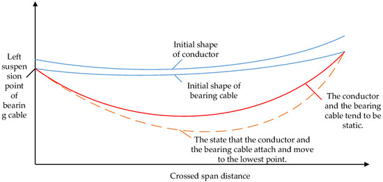
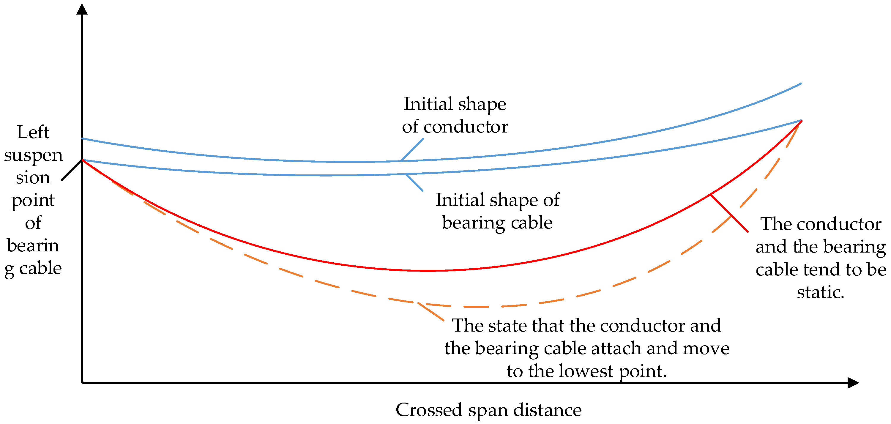
When a suspension-crossing frame breaks down, the conductor moves freely under the action of gravity. After colliding with the bearing cable, they attach to each other and move to the lowest point. After experiencing nonlinear rebound and oscillation, the system tends to become static once the potential energy difference between the conductor and the surroundings is released. The impact coefficient of the bearing cable is a dynamic parameter that describes the maximum impact resistance of the bearing cable. Therefore, the physical state studied in this paper includes the initial shape of the conductor, the initial shape of the bearing cable (safety pay-off condition), and the state in which the falling conductor and the bearing cable move together to the lowest point after attachment (Figure 1).
Figure 1.
The physical state investigated in this study.
2.1.1. Related Settings of Accident Conditions
Relevant assumptions are made about the dynamic impact process of the suspension-crossing frame when a broken-line accident occurs, with the goal of simplifying the problem:
- The conductor and the bearing cable are small and slender force bodies; thus, it is assumed that the conductor and the bearing cable studied in this paper are pure flexible force bodies.
- It is assumed that the conductor and cable studied in this paper are completely elastic bodies with constant elastic modulus, where the elastic modulus of the cable is 3.2 × 10⁴ N/mm2.
- In this paper, the wind load and icing condition are not considered, and the load on the bearing cable in each state is considered according to the uniform distribution. That is, the load on the bearing cable, including the sealing device and the falling conductor, is uniform.
- It is assumed that, after the conductor falls onto the sealing device, the stress and deformation caused by the impact will spread throughout the whole bearing cable at the moment of impact.
- The law of conservation of energy for the system remains established. The impactor and the impacted object are attached to each other and move downward once they are in contact. The process does not rebound; that is, the whole body formed by the attachment of the conductor and the bearing cable still satisfies the law of conservation of energy, and once they are in contact, they move together to the lowest point.
2.1.2. The Initial Gravitational Potential Energy of the Conductor and Bearing Cable
The general form of the known catenary equation is
Among them, the catenary parameter is , and constants and are defined by the boundary conditions.
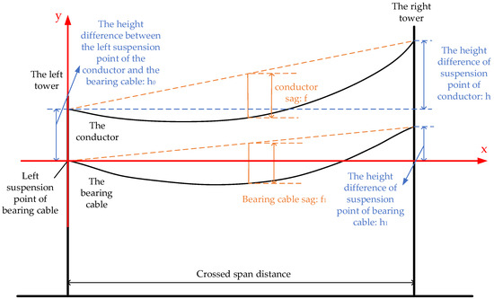
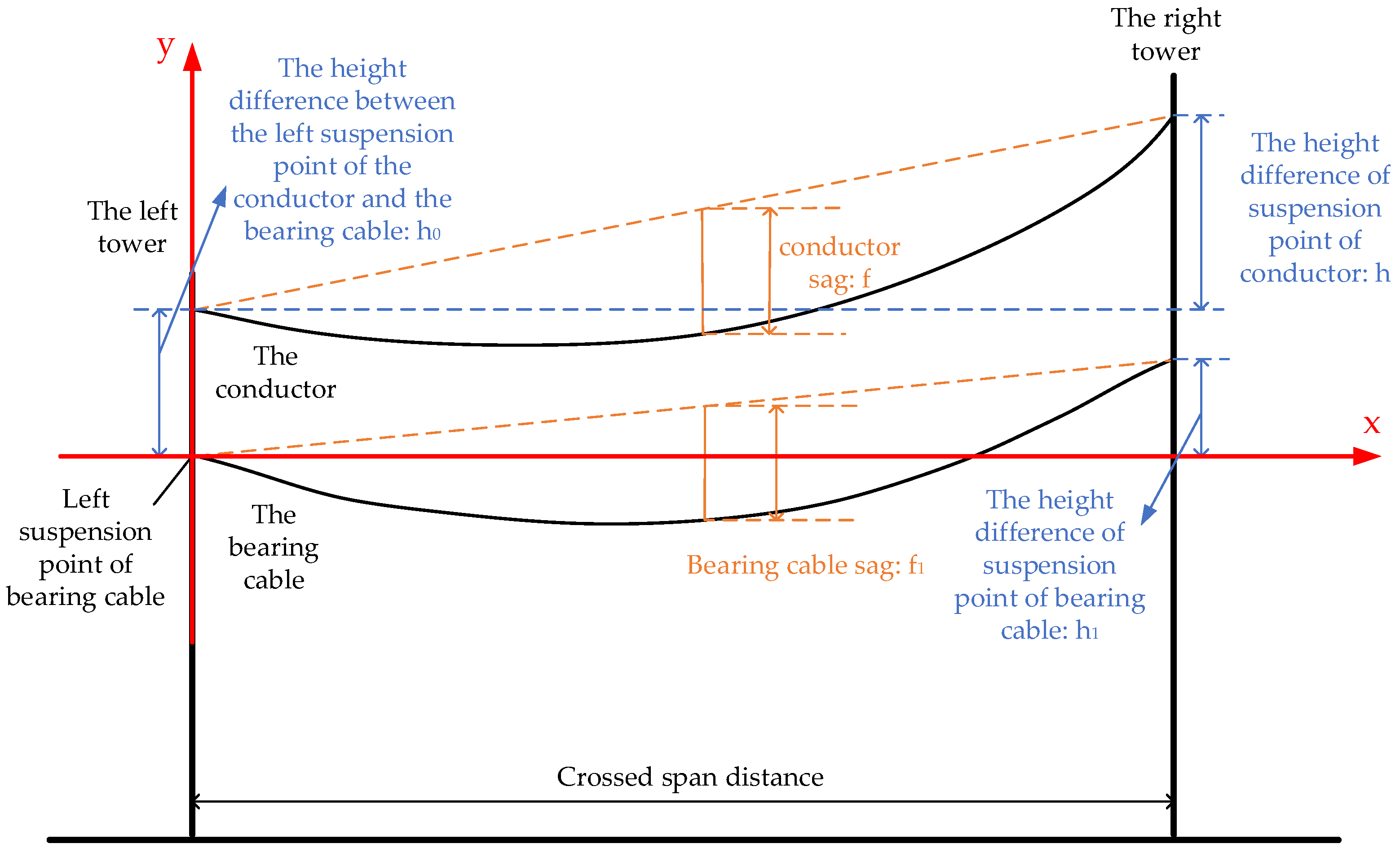
The conductor and the bearing cable in the span are used as the research object, and the left suspension point of the bearing cable is used as the origin of the coordinate. Figure 2 shows that the coordinates of the two suspension points of the initial state conductor are A (0, ) and B (, ), respectively. Substituting the boundary condition into Equation (1), the catenary equation of the initial state conductor can be obtained as follows:
where the constant, , is determined by the equation , , .
Figure 2.
A diagram of the coordinate system.
In the equation, is the modulus of the laying curve of the initial state conductor; is the unit weight of the initial state conductor; is the horizontal tension of the initial state conductor; is the span; is the sag of the span conductor; is the height difference angle of the suspension point of the span conductor; is the height difference of the suspension point of the span conductor; is the height difference between the left suspension point of the conductor and the bearing cable.
The length, , of the suspension line in the initial state of the conductor in the span is
The initial state weight, , of the conductor in the span is
The gravitational potential energy of the known mass element is , and the gravitational potential energy of the whole conductor across the span is .
Given the previous text, we can see that ; therefore,
Let , then , when , ; when , , the above equation becomes
Substituting , into the above equation, we get
Similarly, the coordinates of the two suspension points of the bearing cable are A1 (0, 0) and B1 (, ), respectively, under the safe laying condition. Substituting the boundary condition into Equation (1), the catenary equation of the bearing cable under the safe laying condition can be obtained as follows:
where the constant, , is determined by the equation , , .
In the equation, is the modulus of the setting-out curve of the bearing cable under the safe setting-out condition; is the unit weight of the load-bearing cable under the safe setting-out condition; is the horizontal tension of the load-bearing cable under the safe setting-out condition; is the sag of the span load-bearing cable; is the height difference angle of the suspension point of the span bearing cable; is the height difference of the suspension point of the span bearing cable.
The suspension line length of the bearing cable in the span under the safe setting-out condition is
The weight of the bearing cable in the span under the safe setting-out condition is
The gravitational potential energy of the bearing cable in the span under the safe setting-out condition is
2.1.3. The Gravitational Potential Energy When the Conductor and the Bearing Cable Move to the Lowest Point
When a broken-line accident occurs, the conductor falls onto the bearing cable, and the two are connected as soon as they come into contact. The left suspension point of the bearing cable remains the origin of the coordinate system, and its position is unchanged. The catenary equation, when the whole movement reaches the lowest point, is
where the constant satisfies the equation
In the equation, is the modulus of the pay-off curve of the bearing cable during the broken-line accident.
The line length when the whole movement reaches the lowest point in the span is
At this time, the overall gravitational potential energy is
In the equation, is the equivalent unit weight of the bearing cable in the event of a broken-line accident.
2.1.4. The Increase in the Elastic Potential Energy of the Bearing Cable When It Moves to the Lowest Point
For a uniform elastic overhead line, Hooke ‘s law is followed between the strain and the tension :. Assuming that the original length of the bearing cable is when it is not suspended, when it extends to , the stress of any point is ; that is, .
- where is the total tension of any point of the bearing cable under the safe pay-off condition; is the angle between the tangent of any point of the bearing cable and the horizontal direction; is the elastic modulus of the bearing cable; is the effective cross-sectional area of the bearing cable.
Because the strain of the bearing cable at any time is , when it extends to , the elongation satisfies
Let , then , when , ; when , , the above equation becomes
Substituting and into the above equation, the original length of the bearing cable when it is not suspended is
And because of , when the bearing cable extends from to , the elastic potential energy increment is
2.1.5. Impact Coefficient Calculation
The gravity potential energy when the conductor and the bearing cable move to the lowest point is denoted by ; the elastic potential energy increment when the bearing cable moves to the lowest point from the safe laying condition to the common movement to the lowest point is denoted by ; the initial gravity potential energy of the conductor is denoted by ; the initial gravity potential energy of the bearing cable is denoted by . These all meet the law of energy conservation:
By substituting Equations (7), (11), (15) and (19) into Equation (20), an equation of , , and can be obtained:
where
The weight, , of the conductor and the bearing cable when moving together to the lowest point satisfies
Given this, another equation regarding , , and can be obtained:
The values of , and can be solved by combining Equations (13), (21) and (25).
satisfies
In the equation, is the self-weight of the bearing cable; is the converted single weight of the sealing device; is the number of conductor splits; is the number of bearing cables; is the impact coefficient of the bearing cable; is the net imbalance coefficient; is the length of the falling conductor.
The impact coefficient of the bearing cable is
2.1.6. Calculation of the Comprehensive Safety Factor of the Bearing Cable
Because the bearing cable is the same as the overhead line, the horizontal tension, , of the normal operation state of the bearing cable and the horizontal tension, , of the dynamic load accident state of the bearing cable meet the state equation of the overhead line [19]:
In the equation, , is the height difference between the suspension points of the two bearing cables.
For Equation (24), let
Equation (24) is changed to
It can be obtained that
where
Therefore, the comprehensive safety factor of the bearing cable is
In the equation, is the broken force of the bearing cable.
2.1.7. The Mathematical Model for Calculating the Safety Factor of the Bearing Cable of the Suspension-Crossing Frame
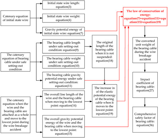
A mathematical model for calculating the safety factor of the bearing cable of the suspension-crossing frame is established using MATLAB (R2023b). First, the variables and parameters needed in the solution process are defined, and the constant C is solved. Then, the objective function is established according to the energy and length equations, and the constraint conditions are applied to obtain the three-dimensional nonlinear equations needed to solve , , and . We can select the appropriate algorithm to obtain the numerical solution of the equations, set its options, obtain the solution, verify its convergence, conduct a sensitivity analysis, and visualize the results. After obtaining the numerical solution of , the numerical solution of the impact coefficient of the bearing cable can be obtained. Finally, the comprehensive safety factor of the bearing cable is determined by the state equation of the overhead line, which assesses the safety risk to the suspension-crossing frame. The specific flowchart for establishing the objective function is shown in Figure 3.
Figure 3.
The calculation process for the safety factor of the suspension-crossing frame’s bearing cable.
2.2. Full-Scale Real-Type Wire-Breaking Impact Test
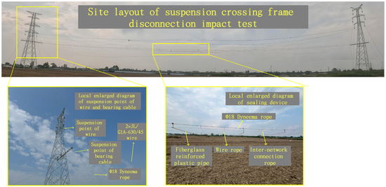
To study the dynamic response of the bearing cable device when the suspension-crossing frame breaks during the actual construction process and verify the validity and accuracy of the calculation method of the safety factor of the suspension-crossing frame’s bearing cable, a full-scale true suspension-crossing frame breaking impact test was conducted on a practical project as a test site (Figure 4).
Figure 4.
Site layout of suspension-crossing frame breaking impact test.
2.2.1. Overview of Test Engineering
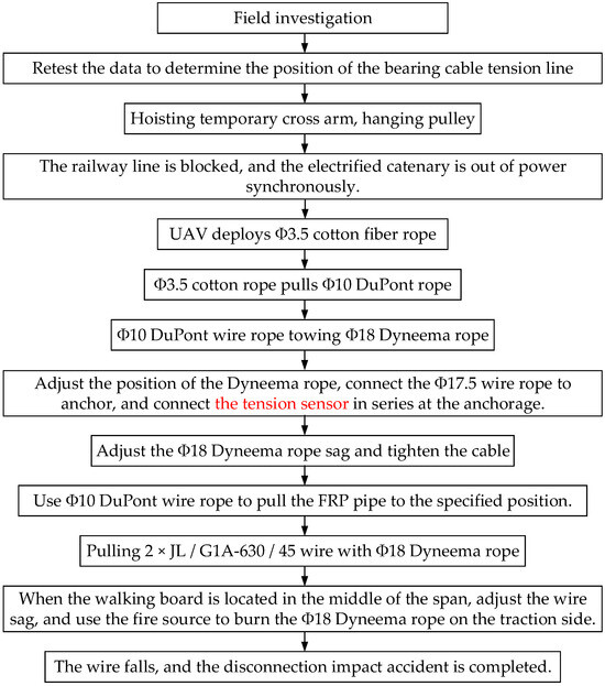
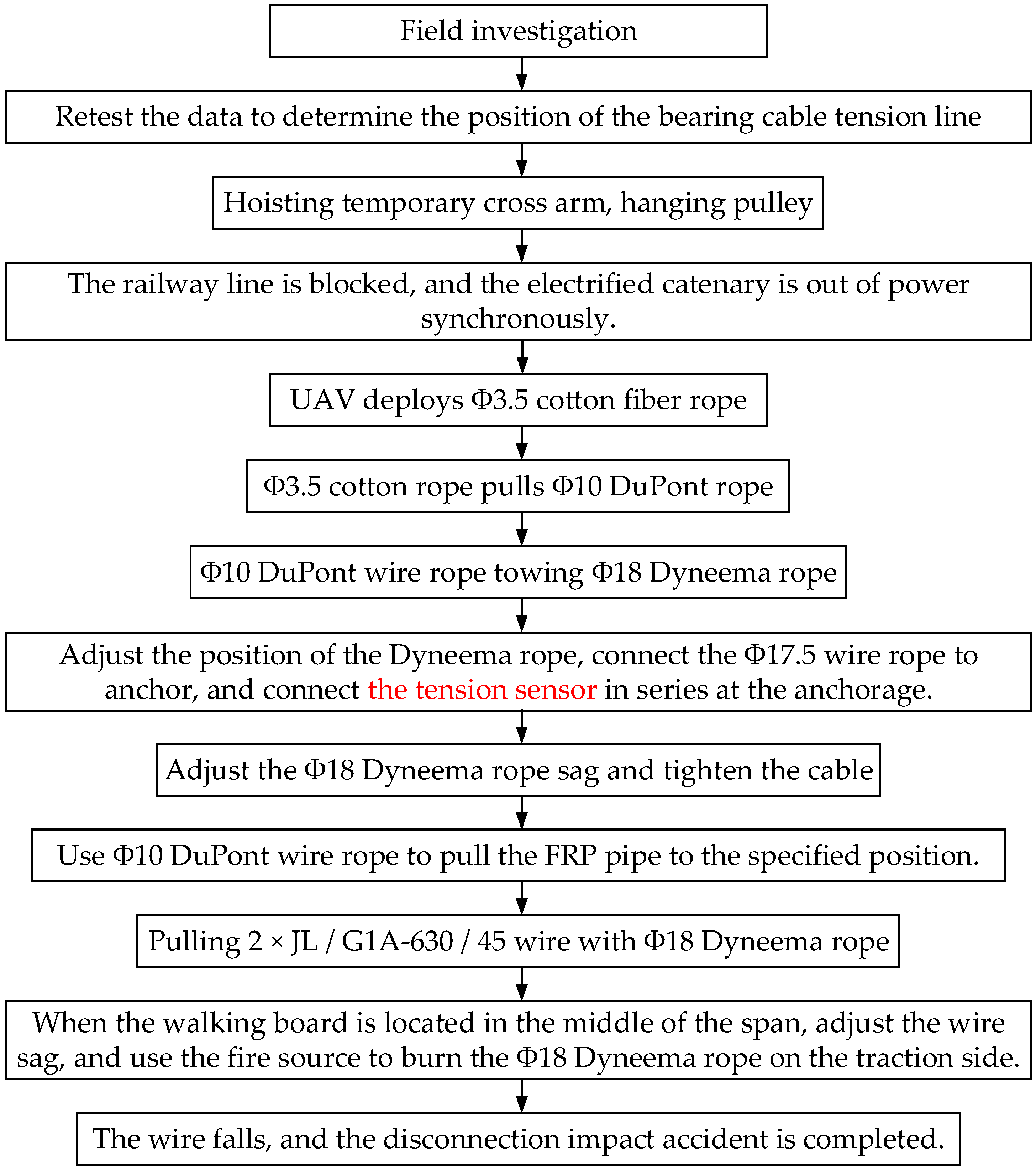
In this project, 2 × JL/G1A-630/45 steel-core, high-conductivity, aluminum-stranded wire is used for the second split-section conductor, and Φ18 Dyneema rope is selected as the bearing cable. The sealing device is composed of 4 glass steel pipes and 4 wire ropes. A WQH-820 three-wheel pulley is suspended on both sides of the tower. On one side, a 5 t tractor winch is used to draw 2 × JL/G1A-630/45 wire through a Φ18 Dyneema rope, and on the other side, the wire is slowly loosened with a brake pay-off plate. When the walking board is located at the center of the span, the wire sag is adjusted so that the distance between the wire and the sealing device exceeds 5 m. The Φ18 Dyneema rope on the traction side is burned by the fire source, and the wire falls to simulate the effect of the wire breaking impact on the current span of the wire. The crossing parameters are shown in Table 1. The specific test flow chart is shown in Figure 5.
Table 1.
The spanning parameters of the suspension-crossing frame impact test.
Figure 5.
Shock test process of suspension-crossing frame disconnection.
2.2.2. Test Scheme
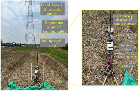
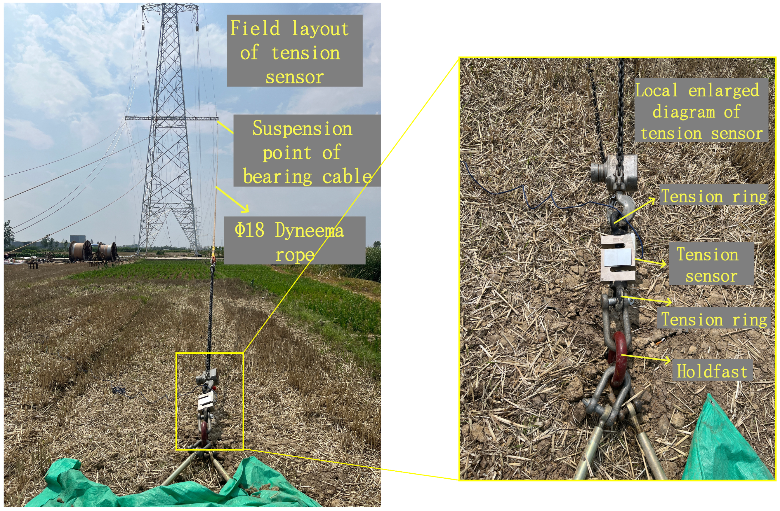
- To measure the change in tension of the bearing cable (Dyneema rope) when the wire is broken and impacted, the total tension transmitted from the bearing cable to the anchorage end is directly and accurately measured, ensuring measurement accuracy and improving the feasibility and safety of project implementation. A tension sensor (Transcell Technology, Inc., Chicago, IL, USA) is arranged at the connection of the bearing cable to the anchor, and the tension ring is connected in series at the shackle of the connection of the bearing cable to the anchor (Figure 6).Figure 6. Site layout of bearing cable tension sensor.
- To accurately capture the geometric shape and sag change of the bearing cable before and after the impact of the broken-line, high-precision three-dimensional laser scanning technology is used to perform non-contact dynamic monitoring of the test process. The scanner is positioned about 10 m to the side of the spanning frame and mounted on a stable tripod to ensure that the scanner’s central axis is roughly perpendicular to the plane of the bearing cable, thereby achieving the best point cloud density and accuracy.
3. Results
3.1. Test Results and Analysis
3.1.1. Test Result
Tension Change of Bearing Cable
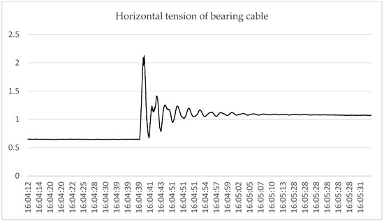
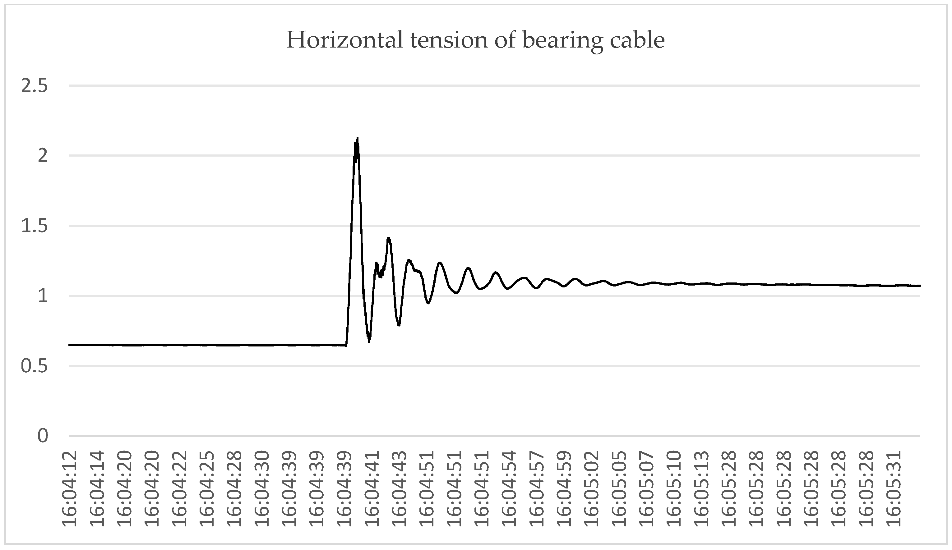
Table 2 and Figure 7 shows that after the broken-line accident, the maximum horizontal tension of the bearing cable is 2.125 t = 21.250 kN; that is, after the conductor is off the grid, the horizontal tension of the bearing cable and the sealing device under the maximum impact force and unbalanced force is 21.250 kN. When it tends to be static, the horizontal tension of the bearing cable is 1.044 t = 10.440 kN.
Table 2.
A table of the horizontal tension variation of the bearing cable.
Figure 7.
A diagram of the variation in horizontal tension of the bearing cable with time.
Morphological Changes in Sealing Device
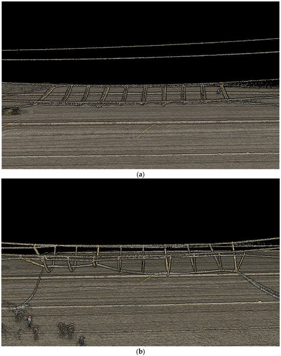
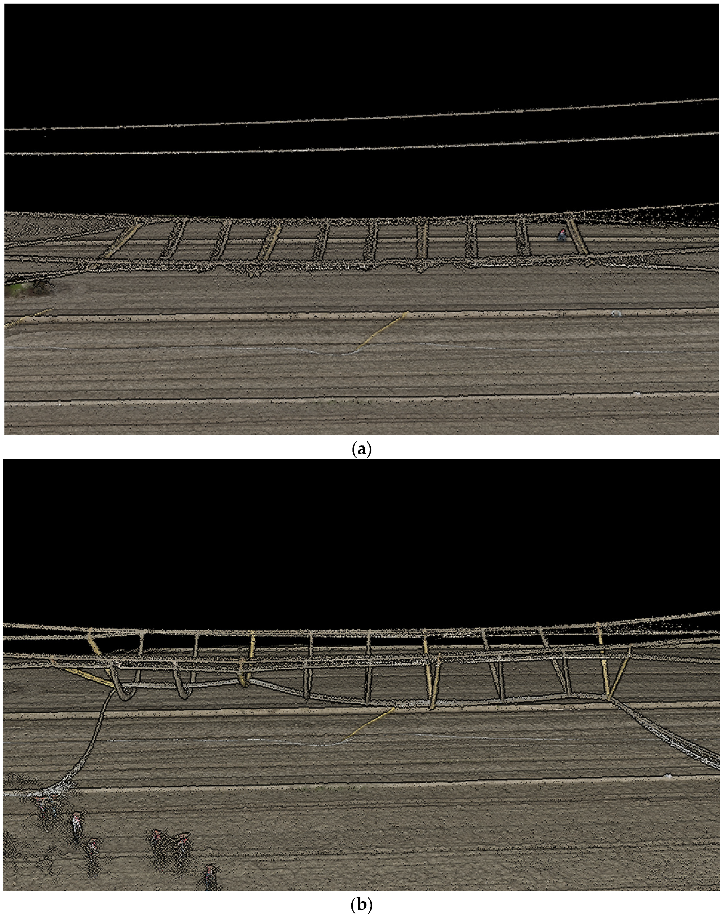
As shown in the three-dimensional point cloud model, the morphological changes in the sealing device before and after the breaking-impact accident can be observed. The specific data are shown in Table 3, and the point cloud diagram is shown in Figure 8.
Table 3.
A table of sealing device parameter changes.
Figure 8.
A schematic diagram of the net sealing device before and after the broken-line accident (based on a 3D point cloud model). (a) The shape of the sealing device before the broken-line accident; (b) the shape of the sealing device after the broken-line accident.
Table 3 shows that the sag of the sealing device before the disconnection accident is 14.27 m, and after the disconnection accident, it is 18.80 m, indicating a decrease of 4.53 m. The fracture of the FRP pipe after the impact of the falling wire reduces the width of the sealing device; simultaneously, the lowest point decreases by 4.376 m, and the sag of the sealing device increases by 2.08 m. The sag of the sealing device is the vertical difference between the lowest point of the sealing device and the bearing cable. The increase in sag reduces the clearance between the sealing device and the crossing object, which may cause the crossing frame to fail to meet the minimum safety electrical distance requirements. To ensure that the clearance distance between the net sealing device and the object to be crossed still meets the requirements of safe distance after the disconnection accident, it is necessary to improve the design and calculation accuracy of the suspension-type crossing frame.
3.1.2. Test Data Analysis
The Calculation of the Real Value of the Impact Coefficient and the Comprehensive Safety Factor of the Bearing Cable
The initial sag of the bearing cable is known, and the horizontal tension of the normal operation state of the bearing cable can be calculated:
In this test, the maximum horizontal tension of the bearing cable is 21.250 kN. Substituting into Equation (28), the converted single true value of the bearing cable under dynamic load accident can be obtained as N/m.
Substituting N/m into Equation (26), the real value of the impact coefficient of the bearing cable in this test is , and the real value of the comprehensive safety factor is .
Accuracy Verification of Safety Factor Calculation Method
The actual engineering parameters of the broken-line impact test are substituted into the calculation method for the safety factor of the bearing cable of the suspension-crossing frame based on the energy equation, and the results are compared with the test data. The results are shown in Table 4.
Table 4.
The results of the mathematical model analysis compared with the test data.
Table 4 shows that because this paper mainly studies the safety performance of the suspension-crossing frame in general, that is, without considering the wind load and icing condition, the initial weight calculation of the conductor and the bearing cable is slightly lower than the actual value, which leads to the calculation value of the converted single weight of the bearing cable in the disconnection accident being slightly lower than the actual value, and the calculated value of the comprehensive safety factor of the bearing cable is slightly higher than the actual value. In addition, the model simplifies the collision energy dissipation, and there is also a difference between the equivalent static analysis and the real dynamic response. In summary, the error of the evaluation model is within a reasonable range.
3.2. The Influence of Construction Condition Change on the Safety Performance of Bearing Cable
The traditional static calculation method defines that the impact coefficient of the bearing cable is 1.67 in the single-circuit line and 2.89 in the double-circuit line. The calculation method for the safety factor of the suspension-crossing frame’s bearing cable, based on the law of conservation of energy, can determine the impact coefficient under different working conditions and improve the accuracy of the accident tension and the comprehensive safety factor of the bearing cable. Taking a practical project as an example, this section studies the variation law of the impact coefficient of the bearing cable, the horizontal tension of the broken-line accident, and the comprehensive safety factor when the specification of the bearing cable and the span of the span change, respectively, and obtains the minimum bearing cable specification and the maximum allowable span that can be used in the project to meet the safety requirements.
3.2.1. Project Profile
The specific crossing parameters of a 220 kV transmission project suspension crossing high-speed railway are shown in Table 5.
Table 5.
The crossing parameters.
The conductor specification parameters are shown in Table 6.
Table 6.
The conductor specification parameters.
3.2.2. Optimization of Bearing Cable Selection
In the actual construction of the suspension-crossing frame, the construction party usually directly selects Φ22 Dyneema rope for insulation of the bearing cable according to experience, and some impact simulation tests use Φ22 Dyneema rope as the research object. However, after a comparative analysis, Φ22 Dyneema rope often results in a safety surplus, increases the difficulty of construction operations for construction personnel, and reduces the economic efficiency of crossing construction.
On this basis, the impact coefficient of the bearing cable; the horizontal tension of the broken-line accident; and the comprehensive safety factors of the Φ22, Φ20, Φ18, Φ16, Φ14, Φ12, and Φ10 Dyneema ropes are calculated. According to the existing suspension crossing construction process guidelines, “DL/T5301-2015”, the comprehensive safety factor of the suspension-crossing frame should not be less than 6. In this study, the analysis of the bearing cable’s safety characteristics is used as the judgment standard. The relevant specification parameters of Dyneema rope are shown in Table 7.
Table 7.
Dyneema rope specification parameters.
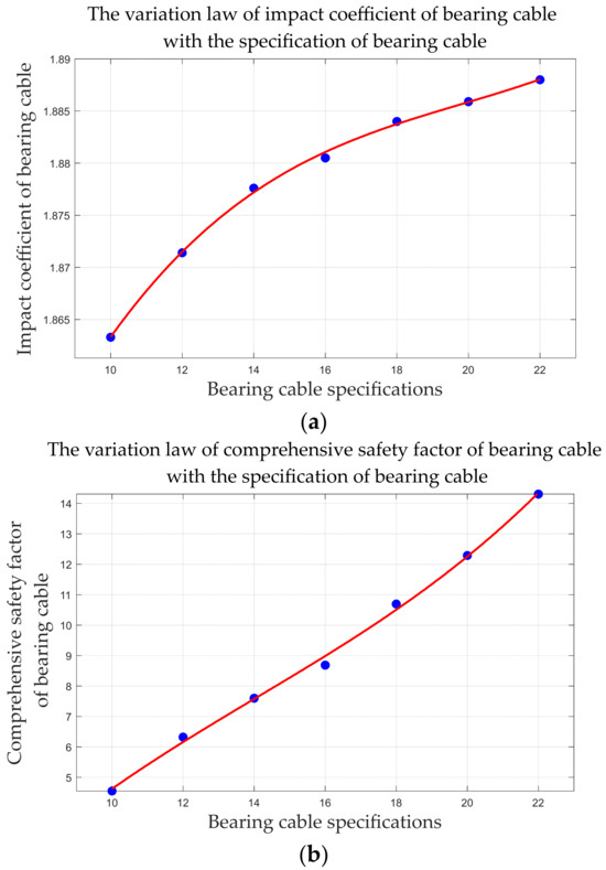
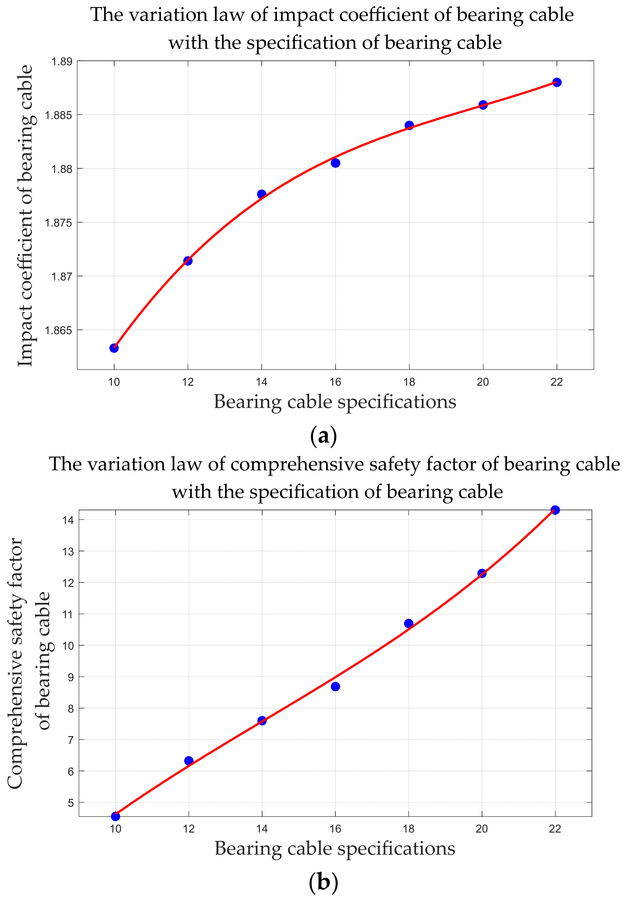
The above construction parameters are substituted into the calculation method for the bearing cable safety factor based on the energy equation to calculate the impact coefficient of the bearing cable, the horizontal tension under disconnection, and the comprehensive safety factor for various Dyneema rope specifications. The results are shown in Table 8 and Figure 9.
Table 8.
The change in the comprehensive safety factor of the bearing cable with the bearing cable specification during the broken-line accident.
Figure 9.
The variation law of the impact coefficient and comprehensive safety factor of bearing cable with the specification of bearing cable. (a) The variation law of the impact coefficient of bearing cable with the specification of bearing cable; (b) the variation law of the comprehensive safety factor of bearing cable with the specification of bearing cable.
The analysis results show that, when the JL/G1A-630/45 conductor breaks under this working condition, the converted single weight, impact coefficient, horizontal tension, and comprehensive safety factor for the bearing cable decrease as the Dyneema rope specification decreases. Among them, the change law of the impact coefficient can be fitted as , and the change law of the comprehensive safety factor can be fitted as . The project uses Φ12 Dyneema rope to meet the safety factor requirement of at least 6. In the actual construction process, the construction unit uses Φ22 Dyneema rope for the insulation section of the bearing cable, based on experience, which results in a safety margin that is too large. According to this method, optimizing the design of the crossing frame can significantly reduce construction costs and improve construction efficiency while ensuring safety.
3.2.3. Calculation of Maximum Allowable Span of Bearing Cable
Based on the bearing cable safety factor calculation method proposed in this paper, the influence of various construction factors on the comprehensive safety factor of the bearing cable can be discussed. This section uses a 220 kV delivery project suspension cable across the high-speed railway as an example to study the same construction conditions. The influence of the change of span on the safety factor of the bearing cable and the maximum span that the same bearing cable can withstand under the same construction conditions are examined.
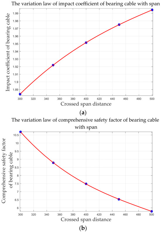
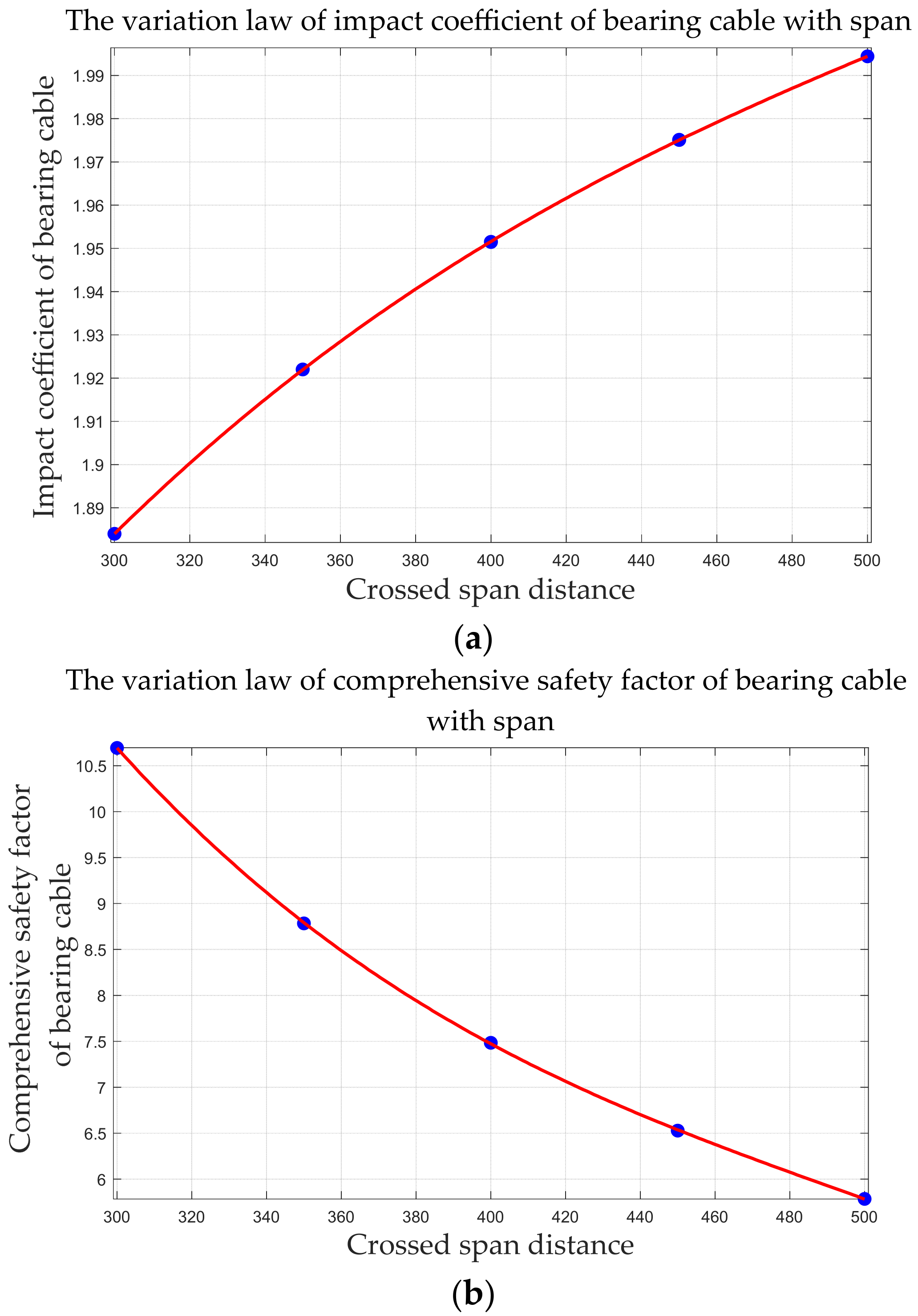
According to the analysis results of Section 3.2.2, to reduce the construction difficulty and cost of crossing construction and retain a certain safety margin to deal with emergencies, Φ18 Dyneema rope is used for the insulation section of the bearing cable. Whether the comprehensive safety factor of the bearing cable exceeds 6 is still used as the criterion. The span increases from 300 to 500 m. The obtained variation law is shown in Table 9 and Figure 10.
Table 9.
The change in the comprehensive safety factor of the bearing cable with span during a broken-line accident.
Figure 10.
Variation law of the impact coefficient and the comprehensive safety factor of the bearing cable with span. (a) The variation law of the impact coefficient of bearing cable with span; (b) the variation law of the comprehensive safety factor of bearing cable with span.
The analysis results show that, when the JL/G1A-630/45 conductor breaks under this working condition, the impact coefficient of the bearing cable and the horizontal tension of the broken-line accident state increase with the increase in span, and the single weight and comprehensive safety factor of the broken-line accident of the bearing cable decrease with the increase in span. The fitting curve equation of the impact coefficient of the bearing cable with the span change rule is , and the fitting curve equation of the comprehensive safety factor of the bearing cable with the span change rule is . Moreover, the maximum span that the Φ18 Dyneema rope can withstand under this accident condition is 450 m; beyond this, it no longer meets the safety regulations.
3.3. Compared with the Results of Traditional Static Analysis
3.3.1. Comparison of Bearing Cable Selection Results
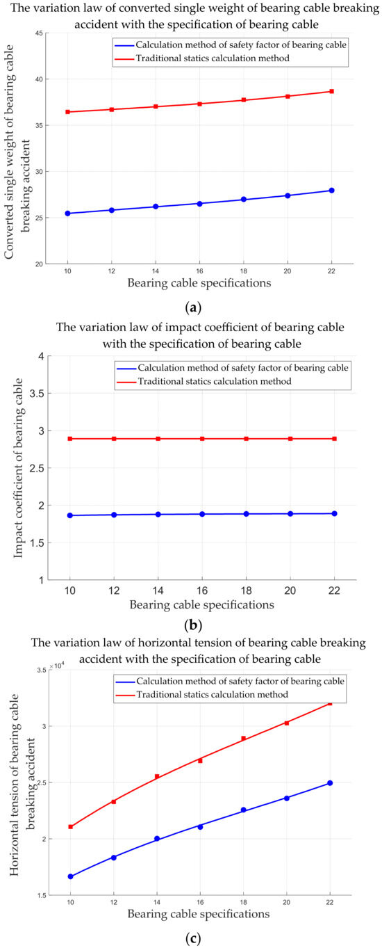
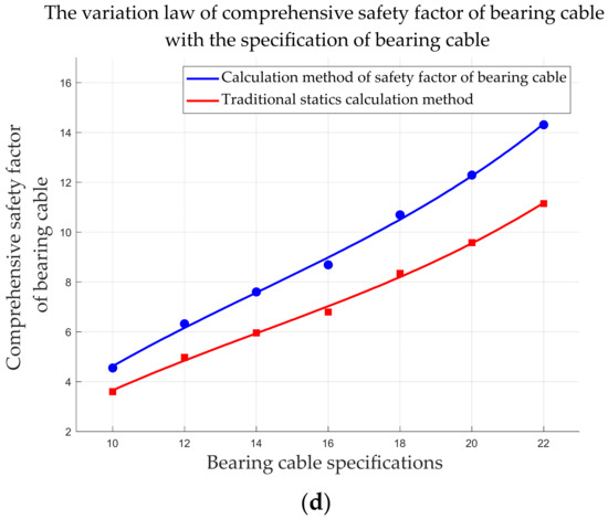
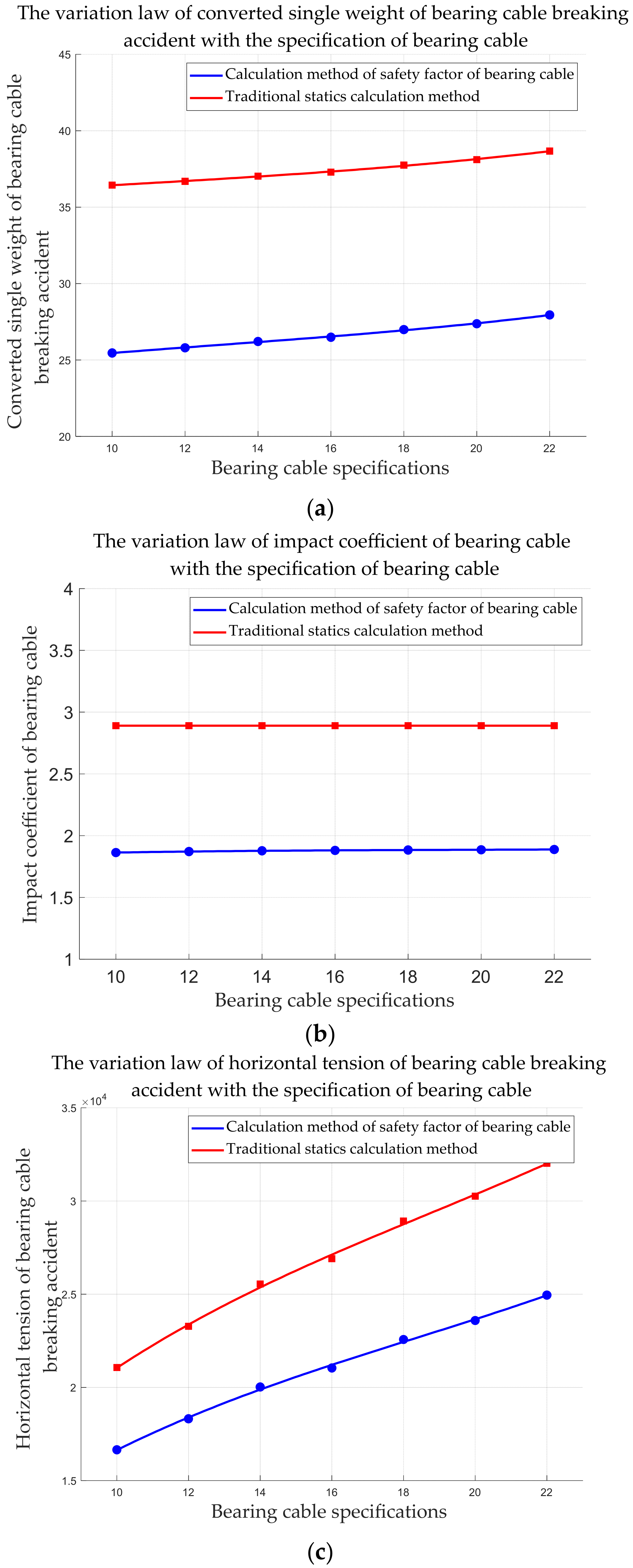
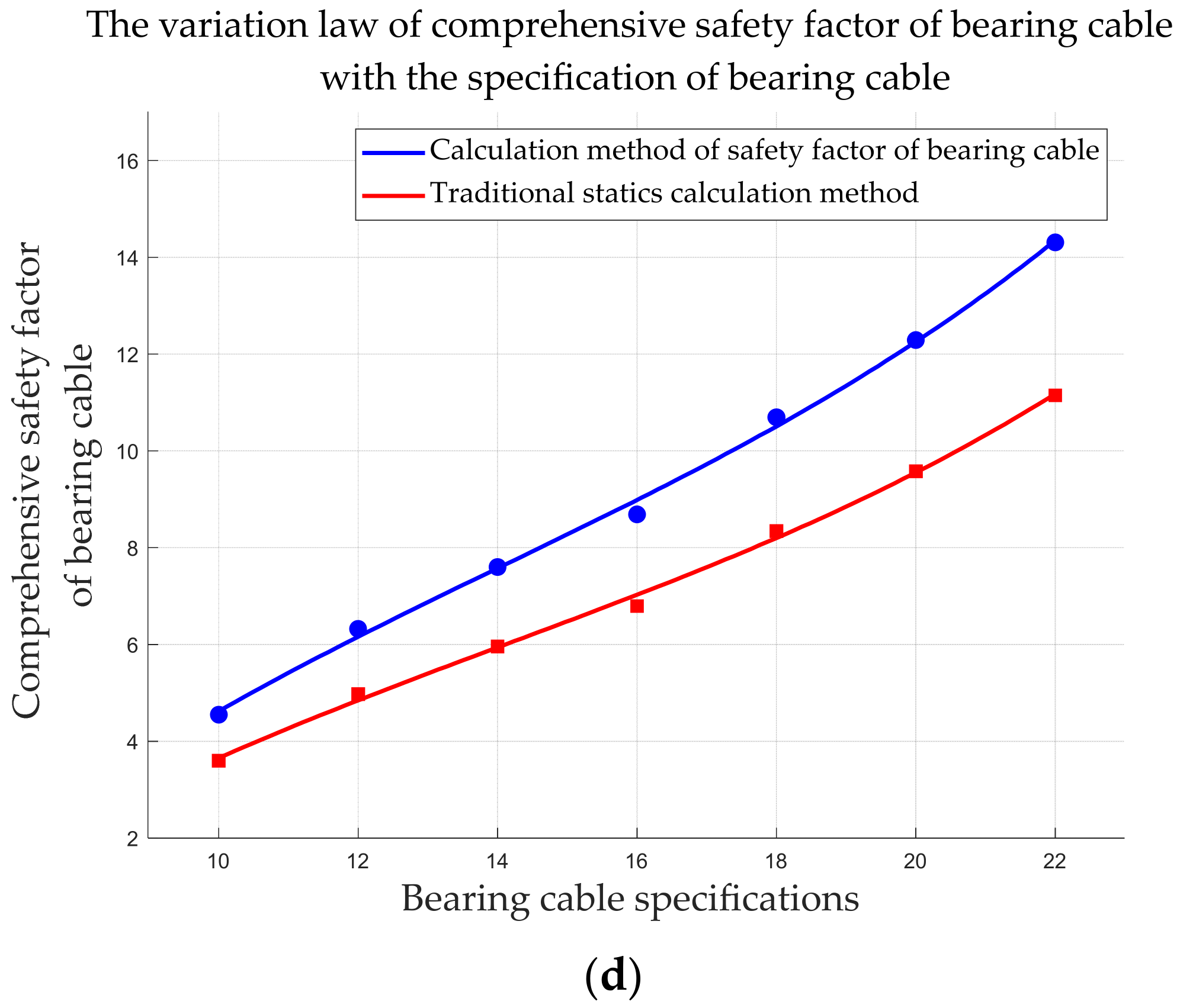
In this paper, the double-circuit overhead line is used as an example, so the impact coefficient of the bearing cable in the traditional statics calculation method is . The safety factor calculation results for the bearing cable in Section 3.2.2 are compared with the traditional static calculation results, and the variation law diagram for each parameter is shown in Figure 11.
Figure 11.
A comparison of bearing cable parameter changes with bearing cable specifications. (a) The variation law of the converted single weight of a bearing cable breaking accident with the specification of the bearing cable; (b) the variation law of the impact coefficient of the bearing cable with the specification of the bearing cable; (c) the variation law of the horizontal tension of a bearing cable breaking accident with the specification of the bearing cable; (d) the variation law of the comprehensive safety factor of a bearing cable with the specification of the bearing cable.
Figure 11 shows that the single weight, horizontal tension, and comprehensive safety factor for the broken-line accident of the bearing cable under the two analysis methods decrease as the bearing cable specification decreases, and the change trends are the same. However, the selection of the impact coefficient of the bearing cable in the traditional statics calculation method does not consider the different impact degree of the conductor falling network under different working conditions, and the value is large, which eventually leads to a low calculation value of the comprehensive safety factor of the bearing cable; that is, the safety margin is too large. According to the calculation results of traditional statics, when the JL/G1A-630/45 conductor breaks under this working condition, it is necessary to use Φ16 Dyneema rope to meet the safety requirements of a safety factor of at least 6. The analysis results in Section 3.2.2 show that Φ12 Dyneema rope can be used. Therefore, in the actual construction process, the calculation method for the safety factor of the bearing cable based on the law of conservation of energy can significantly improve the calculation accuracy of the suspension span design, reduce construction costs, and improve construction efficiency.
3.3.2. Comparison of Maximum Allowable Span Results of Bearing Cable
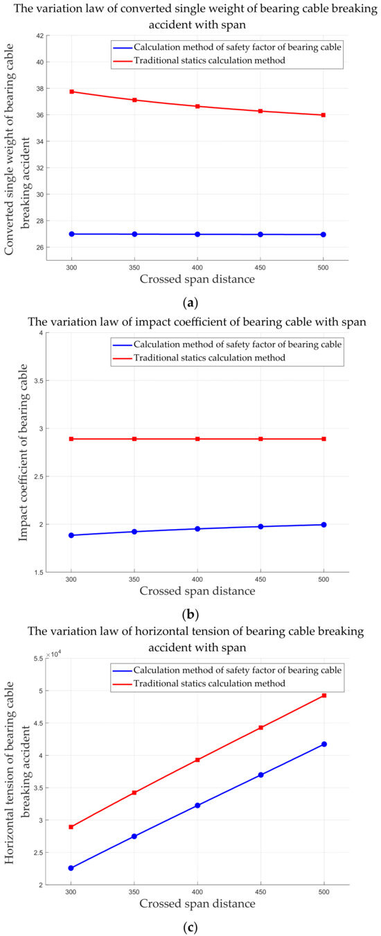
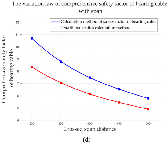
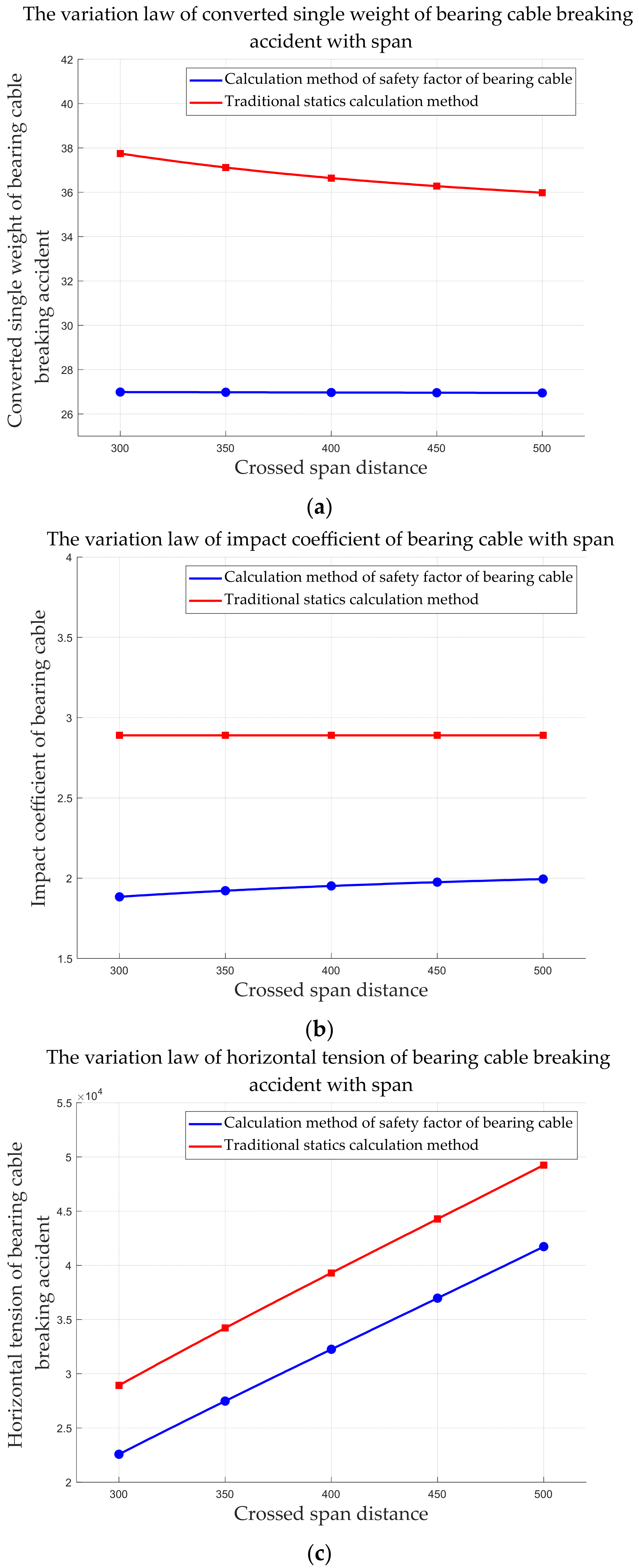
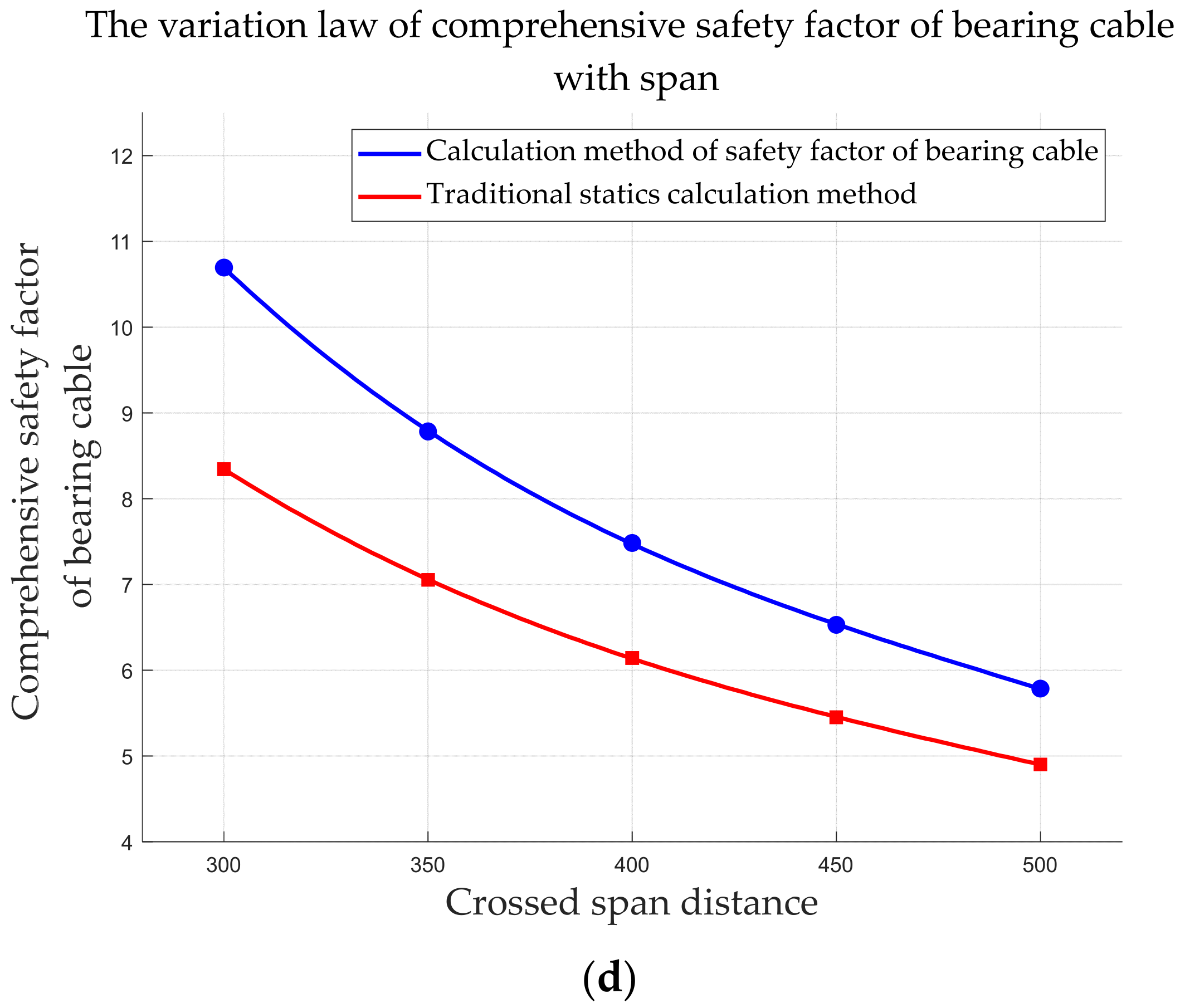
The safety factor calculation results for the bearing cable in Section 3.2.3 are compared with the traditional static calculation results, and a diagram of the variation law for each parameter is shown in Figure 12.
Figure 12.
A comparison diagram of bearing cable parameter changes with the crossed span distance. (a) The variation law of the converted single weight of a bearing cable breaking accident with span; (b) the variation law of the impact coefficient of a bearing cable with span; (c) the variation law of the horizontal tension of a bearing cable breaking accident with span; (d) the variation law of the comprehensive safety factor of a bearing cable with span.
Figure 12 shows that the single weight and comprehensive safety factor of the broken-line accident of the bearing cable under the two analysis methods decrease with the increase in the span, the horizontal tension of the broken-line accident increases with the increase in the span, and the change trend is the same. However, according to the analysis results in Section 3.2.3, the impact coefficient of the bearing cable is lower than that of the traditional statics calculation method and increases with span. Therefore, the traditional statics calculation results show that the maximum span that the Φ18 Dyneema rope can withstand under the accident condition is 400 m, and Section 3.2.3 analysis results show that the maximum span that the Φ18 Dyneema rope can withstand under the accident condition is 450 m. And the comprehensive safety factor of the bearing cable decreases more rapidly with increasing span than in traditional static analysis results. Therefore, this method can be used to study the influence of construction conditions on the impact coefficient and comprehensive safety factor of the bearing cable more efficiently and accurately and provide a reference for the safe design of a suspension-crossing frame.
3.3.3. Comparison with the Test Data
The traditional static calculation results are compared with test data, and the results are shown in Table 10.
Table 10.
The traditional static calculation results compared with test data.
Table 10 shows that the impact coefficient used in the traditional static calculation method has a large error with the actual data, and the influence of the different impact degrees of the conductor falling off on the impact coefficient under different working conditions is not considered, which leads to the calculated comprehensive safety factor of the bearing cable being less than the actual safety factor. The influence on the actual construction process is that the specification of the bearing cable, selected according to the traditional static calculation method, has a large safety margin, which can easily lead to resource waste. It is necessary to optimize the design and calculation methods of the traditional suspension-crossing frame to improve construction efficiency and reduce construction costs.
Table 4 shows that the safety-factor calculation method for the load-bearing cable based on the energy equation can significantly improve the accuracy of the suspension-crossing frame design. The calculation accuracy of the impact coefficient is increased by 31.6%, the calculation accuracy of the horizontal tension of the load-bearing cable is increased by 20.2%, and the calculation accuracy of the comprehensive safety factor is increased by 15.1%. This method can calculate the corresponding impact coefficient for different construction conditions and obtain a more realistic, comprehensive safety factor for the bearing cable. In the actual construction process, the optimal bearing cable specification can be determined using this method, and the construction cost can be minimized while ensuring safety.
4. Discussion
In this study, a method for calculating the safety factor of the bearing cable of the suspension-crossing frame based on the energy equation is proposed, which significantly improves the calculation accuracy of the crossing frame design. A full-scale real-type suspension-crossing frame conductor-breaking impact test is also conducted.
When the suspension-crossing frame is broken, the conductor falls freely under the action of gravity and collides with the bearing cable, adhering to it and moving to the lowest point. In this process, the initial gravitational potential energy of the conductor and the bearing cable satisfies energy conservation with the gravitational potential energy of the whole conductor-bearing cable coupling system at the lowest point, and the elastic potential energy increment as the bearing cable elongates to the lowest point. In Section 2.1, starting with the standardized catenary equation of the overhead line, the plane coordinate system is constructed with the left suspension point of the bearing cable as the coordinate origin. The gravitational potential energy of each state of the conductor and the bearing cable is obtained by integrating the mass element, and the length of each state of the conductor and the bearing cable is determined by integrating the arc length. Then, the incremental elastic potential energy of the bearing cable is obtained from Hooke’s law, and the energy equation is solved to obtain the impact coefficient for the broken-line accident of the bearing cable. Finally, the comprehensive safety factor of the bearing cable is calculated using the state equation of the overhead line, and the relevant program is written in MATLAB (R2023b) to construct the mathematical model for calculating the safety factor.
Simultaneously, this study selected the actual erection site and used high-precision sensor equipment to address the challenges of complex personnel scheduling and significant material loss, and restored the scene of the suspension-crossing frame disconnection impact accident. The test results show that the variation in the tension of the bearing cable over time exhibits an oscillatory attenuation waveform, and the strength of the FRP pipe used in the test is insufficient. After the impact of the falling wire, a fracture occurs, which reduces the distance between the sealing device and the ground. In existing research, experimental verification relies on small-scale tests or simplified dynamic models. Although it provides important insights into disconnection in accidents, its conclusions are often constrained by simplifying assumptions about size and boundary conditions, and there are risks in directly guiding full-scale engineering design [31,32]. Compared with the existing small-scale impact simulation test, the conclusion of this test is more authentic and reliable. The test results provide data support for the calculation method. Through a comparative analysis, the error between the calculated impact coefficient and the test value is 6.7%, and the error between the calculated comprehensive safety factor and the test value is 4.9%. The error is within a reasonable range. This method can be applied to construction design calculations.
Based on this method, the influence of changes in the bearing cable specification and span on the impact coefficient and the comprehensive safety factor of the bearing cable is successfully discussed in Section 3.2. When the construction conditions are determined, the selection of the bearing cable is closely related to the construction efficiency, cost, and safety. Currently, construction parties often use Φ22 Dyneema rope for the insulation section of the bearing cable based on past experience, which lacks a clear theoretical analysis and verification. Using the traditional statics calculation method and mathematical model calculation, the safety margin of Φ22 Dyneema rope is determined to be too large, often more than twice the safety demand, which can reduce construction efficiency and increase construction costs. The mathematical model in Section 3.2.2 shows that the comprehensive safety factor of the bearing cable is 6.3219 when the Φ12 Dyneema rope is selected, and 4.5511 when the Φ10 Dyneema rope is selected. Therefore, the Φ12 Dyneema rope is the critical bearing cable specification under this working condition. At this time, the calculated impact coefficient is 1.8714. The traditional statics calculation method follows the current industry standard “DL/T5301-2015” [19]. Using its specified fixed impact coefficient, the single-loop line is 1.67, and the double-loop line is 2.89, both of which exceed the calculated impact coefficient. The traditional statics calculation results show that Φ16 Dyneema rope is the critical bearing cable specification, which is greater than the calculation result of this method.
The traditional static calculation method and this method calculate the horizontal tension and the comprehensive safety factor of the load-bearing cable in the accident state using the state equation of the overhead line. The difference lies in the selection of the impact coefficient. As shown in the analysis results in Section 3.2.2, the impact coefficient of the bearing cable decreases with decreasing load-bearing cable specification and is lower than the traditional value. Therefore, the results of Section 3.3.1 show that the comprehensive safety factor of the bearing cable decreases as the bearing cable specification decreases, but the analysis results of this method decrease more rapidly and exceed those of the traditional static analysis. This means that, in the actual construction process, the Φ22 Dyneema rope (with too high of a safety margin) is often selected based on experience, and the traditional static analysis method also has the disadvantage of too high of a safety margin.
The same phenomenon occurs when the maximum allowable span of the bearing cable is discussed. The analysis results in Section 3.2.3 show that the maximum allowable span of the bearing cable is 450 m when Φ18 Dyneema rope is used for the same project. The results in Section 3.3.2 show that the maximum allowable span calculated by the traditional static analysis method is 400 m. Similarly, because the traditional value of the impact coefficient exceeds the calculated value, the comprehensive safety factor of the bearing cable is lower. That is, the traditional static analysis method not only provides a high safety margin in selecting the bearing cable but is also conservative in determining the limit under extreme construction conditions. Therefore, the method proposed in this study not only improves the calculation accuracy of the suspension-crossing frame design but also addresses the issue that the safety calculation is overly conservative.
In addition, the traditional static analysis results are compared with experimental data. The results show that the error between the impact coefficient from the traditional method and the actual data is 38.3%, indicating a large error. This method improves the calculation accuracy of the impact coefficient by 31.6%. The comprehensive safety factor is increased by 15.1%.
Existing research has developed a wealth of numerical and simulation models. For example, Yong, M et al. [23] established a simulation model of the impact of the rope and also studied the influence of different spans on the horizontal tension and comprehensive safety factor of the cable-breakage accident. This kind of method can analyze the transient dynamic response to impact, but the method proposed in this study offers significant advantages in computational efficiency and engineering design. It avoids the uncertainty of complex contact definitions and material nonlinear models and enables reliable checking of key design parameters at very low computational cost, making it more suitable for rapid safety checks in the design stage.
The method proposed in this study provides designers with a high-precision safety-factor evaluation tool that can replace the fixed empirical coefficient in the current specification. For projects that span important facilities or complex working conditions, using this tool to verify calculations can upgrade the design method from “rough estimation” to “accurate calculation” and improve the design’s safety and economy from the outset. Based on the analysis of the influencing factors in this paper, the selection table for the bearing cable under specific working conditions can be compiled. For example, when the 220 kV commonly used JL/G1A-630/45 wire spans 300, 350, 400, and 450 m, the optional minimum bearing cable specifications are Φ12, Φ14, Φ16, and Φ18 Dyneema ropes, respectively. This provides a direct basis for the rapid selection and optimization of the bearing cable and helps to achieve the optimal balance between safety and cost in the construction scheme design stage. The damage phenomenon of the sealing device in the full-scale test shows that in construction, we must attach great importance to the material quality of the sealing device and improve its impact resistance.
However, the current calculation method of the safety factor of the bearing cable still has some limitations: this study does not consider the wind load and icing conditions, which affect the calculation of the initial weight of the wire and the load-bearing cable, leading to a slightly higher value of the comprehensive safety factor and affecting the judgment of the safety performance to a certain extent. There are few test data, and the accuracy verification of the method is accidental. Thus, it is necessary to increase the size of the test data to provide stronger support.
In this paper, the calculation method for the impact coefficient and safety factor of the bearing cable is proposed by analyzing the energy transformation law of the suspension crossing-frame disconnection accident. The influence of construction factors on the comprehensive safety factor of the bearing cable is discussed, and the method’s accuracy is verified through a full-scale true-disconnection impact test. In the future, research can be continued in the following aspects:
- A mathematical model for calculating the safety factor of the bearing cable of the suspension-crossing frame, considering wind load and icing, can be constructed. Compared with the results of this test, we can determine whether the accuracy can be improved.
- The full-scale test in this study was conducted only once. Although the model’s accuracy under specific working conditions has been verified, its wide applicability across different voltage levels, conductor types, and complex environmental conditions still needs further verification and support with more tests and engineering example data in the future.
- Based on the current glass fiber-reinforced plastic pipe fracture in this test, it can be studied whether the sealing device material can be optimized to improve the impact resistance of the suspension-crossing frame.
5. Conclusions
In this paper, the energy transfer mathematical model of the impact-bearing cable after the existing wire fracture cannot accurately describe the physical process, and the value of the fixed broken-line impact coefficient (such as 2.89 for the double circuit) used in the design specification is not accurate enough, resulting in a large deviation in the calculation of the safety factor of the bearing cable. The energy change law of the impact-bearing cable of the wire during the broken-line accident is analyzed in detail. Based on this, an efficient and accurate method for calculating the impact coefficient and the safety factor of the bearing cable is proposed, and the mathematical model for the safety factor of the bearing cable is established. Simultaneously, it overcomes the problems of complex scheduling and the high cost of a full-size true disconnection impact test, and includes tests to verify the method’s accuracy. Then, using a practical project as an example, the influence of construction parameters on the impact coefficient and the comprehensive safety factor of the bearing cable is discussed and compared with the traditional static calculation method. The conclusions are as follows:
- According to the example analysis, against the background of a suspension crossing for a high-speed railway project, the converted single weight, horizontal tension, and comprehensive safety factor for the broken-line accident of the bearing cable were all found to decrease according to the bearing cable specification. The traditional static calculation method follows the fixed impact coefficient specified in the current industry standard. The single-circuit line is 1.67, the double-circuit line is 2.89, and the value is large. The critical specification of the bearing cable is Φ16 Dyneema rope. The calculation method proposed in this paper shows that the Φ12 Dyneema rope can meet the safety requirements. This method can improve the calculation accuracy of suspension span design, quickly and accurately select the bearing cable, reduce construction costs, and improve construction efficiency.
- When the construction conditions and the bearing cable specifications are determined, the converted single weight and the comprehensive safety factor for the broken-line accident of the bearing cable decrease with increasing span. The horizontal tension and impact coefficient of the broken-line accident increase with the increase in the span, and there is a maximum allowable span. The calculation result of the calculation method proposed in this paper is 450 m, and the traditional static calculation result is 400 m. The model clarifies the method for defining the limit working condition of the crossing frame.
- In this paper, the double-circuit project is used as an example to conduct the test. The impact coefficient test data is 2.09, and the error between the traditional value and the test value is 38.3%. In the actual construction process, it is easy to select the bearing cable specification too generously, resulting in resource waste. The calculated impact coefficient is 1.95; the error relative to the experimental value is 6.7%, and the calculation accuracy is improved by 31.6%. The calculation method can determine the specific impact coefficient value for different construction conditions and can be applied to calculate the comprehensive safety factor of the bearing cable.
- Through application analysis, this method can efficiently and accurately calculate the specific values of the impact coefficient and the comprehensive safety factor of the bearing cable-breakage accident, optimize the selection method of the bearing cable, and define the limit working condition range of the crossing frame to maximize the construction efficiency and economy while meeting safety requirements. It also has good general analysis ability. Based on the analysis of the influencing factors, the selection table for the bearing cable under specific working conditions can be compiled—for example, when the span of a 220 kV common JL/G1A-630/45 conductor is 300, 350, 400, and 450 m, the optional minimum bearing cable specifications are Φ12, Φ14, Φ16, and Φ18 Dyneema ropes, respectively. The results of this study can help construction personnel quickly select appropriate bearing cable specifications, greatly improve the construction efficiency of suspension-crossing frames, and provide important guidance for the design of construction schemes.
Author Contributions
Conceptualization, S.W. and Y.S.; methodology, S.W., B.T. and Y.S.; software, Q.H., G.Z. and P.Z.; validation, S.W., Y.S., Q.H., G.Z. and P.Z.; formal analysis, K.L. and H.G.; investigation, Y.S., Q.H. and P.Z.; resources, G.Z. and Q.H.; data curation, S.W. and P.Z.; writing—original draft preparation, S.W. and Y.S.; writing—review and editing, S.W., B.T., Y.S., Q.H. and G.Z.; visualization, K.L.; supervision, S.W. and B.T.; project administration, H.G.; funding acquisition, B.T. All authors have read and agreed to the published version of the manuscript.
Funding
This research received no external funding.
Data Availability Statement
The original contributions presented in the study are included in the article; further inquiries can be directed to the corresponding author.
Conflicts of Interest
Authors Qiyun Han, Kai Li, Guanmin Zhu, Hehuai Gui, Pengcheng Zhang were employed by the company Anhui Electric Power Transmission & Transformation Co., Ltd. The remaining authors declare that the research was conducted in the absence of any commercial or financial relationships that could be construed as a potential conflict of interest.
References
- Li, R.; Qi, L.; Dong, Y.-R.; Wang, H. Nonlinear Performance of Steel Tube Tower in Ultra-High Voltage Transmission Lines under Wind Loads. Buildings 2024, 14, 140. [Google Scholar] [CrossRef] [Scilit]
- Sospiro, P.; Amarnath, L.; Di Nardo, V.; Talluri, G.; Gandoman, F.H. Smart Grid in China, EU, and the US: State of Implementation. Energies 2021, 14, 5637. [Google Scholar] [CrossRef] [Scilit]
- Liu, X.; Zhang, J.; Hu, Y.; Liu, J.; Ding, S.; Zhao, G.; Zhang, Y.; Li, J.; Nie, Z. Carbon Emission Evaluation Method and Comparison Study of Transformer Substations Using Different Data Sources. Buildings 2023, 13, 1106. [Google Scholar] [CrossRef] [Scilit]
- Ma, L. Inter-Provincial Power Transmission and Its Embodied Carbon Flow in China: Uneven Green Energy Transition Road to East and West. Energies 2022, 15, 176. [Google Scholar] [CrossRef] [Scilit]
- Li, Z.; Wang, Z.; Li, J.; Liu, S. Experimental Study on Vortex-Induced Vibration of Steel Tubes in Transmission Towers at Various Inflow Conditions. Buildings 2023, 13, 252. [Google Scholar] [CrossRef] [Scilit]
- He, R.; Wan, P.; Yang, M. The resource curse in energy-rich regions: Evidence from China’s ultra-high voltage transmission. Energy 2024, 304, 132153. [Google Scholar] [CrossRef] [Scilit]
- Wang, S.; Guo, Z.; Zhu, G.; Zhang, P.; Han, Q.; Tang, B. Analysis of Mechanical Properties of Steel Tube Crossing Frame for Power Transmission Project. Metals 2026, 16, 299. [Google Scholar] [CrossRef] [Scilit]
- Zhang, S.; Jiang, W.; Guo, Z.; Yu, F.; Liu, J.; Tian, L. Study on the Impact of Additional Insulator String Fracture on the Safety Status of Transmission Lines Under Large Ice Loads. Buildings 2025, 15, 4131. [Google Scholar] [CrossRef] [Scilit]
- Li, F.; Li, H.; Wang, Y.; Qin, J.; Chen, P. A Transient Multi-Feed-In Short Circuit Ratio-Based Framework for East China: Insights into Grid Adaptability to UHVDC Integration. Energies 2025, 18, 4488. [Google Scholar] [CrossRef] [Scilit]
- Qin, Q.; Tu, X.; Hu, Y.; Wang, Z.; Yu, L.; Hou, S. Modeling and Loading Effect of Wind on Long-Span Cross-Rope Suspended Overhead Line with Suspension Insulator. Buildings 2024, 14, 656. [Google Scholar] [CrossRef] [Scilit]
- Song, S.; Li, S.; Liang, Y.; Huo, R.; Song, Z.; Miao, Z.; Song, Z. Study on Construction Mechanical Effect and Optimization of Large-Span Variable Cross-Section of Railway Tunnel. Buildings 2023, 13, 2859. [Google Scholar] [CrossRef] [Scilit]
- Woldemariam, A.M.; Oyawa, W.O.; Nyomboi, T. Structural Performance of uPVC Confined Concrete Equivalent Cylinders Under Axial Compression Loads. Buildings 2019, 9, 82. [Google Scholar] [CrossRef] [Scilit]
- Zhao, G.; Wang, M.; Liu, Y.; Zhang, M. Dynamic Response of Transmission Tower-Line Systems Due to Ground Vibration Caused by High-Speed Trains. Buildings 2023, 13, 2884. [Google Scholar] [CrossRef] [Scilit]
- Wang, S.; Li, C.; Zhong, W.; Li, K.; Gui, H.; Tang, B. Mechanical Characteristics Analysis and Structural Optimization of Wheeled Multifunctional Motorized Crossing Frame. Appl. Sci. 2026, 16, 3034. [Google Scholar] [CrossRef] [Scilit]
- Huang, C.; Wang, Y.; Xu, S.; Shou, W.; Peng, C.; Lv, D. Vision-Based Methods for Relative Sag Measurement of Suspension Bridge Cables. Buildings 2022, 12, 667. [Google Scholar] [CrossRef] [Scilit]
- Yi, C.; Xiao, E.; Tan, X.; He, Z.; Xiang, Y.; Li, L. Research on the Refined Main Cable Shape-Finding Algorithm for Long-Span Suspension Bridges. Buildings 2024, 14, 3233. [Google Scholar] [CrossRef] [Scilit]
- Li, J.; Wang, B.; Wang, T.; Li, Z. Nonlinear Finite Element Analysis and Fatigue Damage Assessment of Wind-Induced Vibration for the Tension Cable-Supported Power Transmission Structure. Buildings 2023, 13, 2924. [Google Scholar] [CrossRef] [Scilit]
- Zhao, Y.; Fu, Y.; Zhu, Y.; Su, B. Reliability Analysis of Degraded Suspenders of Long-Span Suspension Bridge under Traffic Flow Braking. Buildings 2024, 14, 2333. [Google Scholar] [CrossRef] [Scilit]
- DL/T 5301-2015; Construction Technology Guidelines for Overhead Transmission Lines Without Crossing Overhead Transmission Lines Without Power Cu. China Electricity Council: Beijing, China, 2014.
- Zhan, Z.; Zeng, Y. Research on calculation method of non-crossing overhead transmission line sealing network. J. Electr. Power 2021, 36, 173–181. [Google Scholar] [CrossRef]
- Zhang, Y. Research on calculation method of non-crossing overhead transmission line sealing network. China’s New Technol. New Prod. 2024, 22, 87–89. [Google Scholar] [CrossRef]
- Xia, Y.; Hu, Y.; Wan, J.; Jia, N. Dynamic Analysis of Wire Impact Suspension Crossing Frame. Mach. Des. 2018, 35, 137–141. [Google Scholar] [CrossRef]
- Ma, Y.; Jiu, J.; Zhang, H.; Yi, N. Study on the influence law of impact resistance of suspension crossing frame of transmission line. Power Eng. Technol. 2021, 40, 75–82. [Google Scholar] [CrossRef]
- Meng, S.; Shen, W.; Tang, B. Simulation analysis of collision between traction wire and sealing net in live crossing construction. J. Three Gorges Univ. (Nat. Sci. Ed.) 2020, 42, 91–95. [Google Scholar] [CrossRef]
- Min, C. Transmission Line Engineering Without Crossing Across the Line Technology; China Electric Power Press: Beijing, China, 2009; Available online: http://opac.nlc.cn (accessed on 1 March 2026).
- Soleimani, F.; Si, G.; Roshan, H.; Zhang, Z. Numerical modelling of coal and gas outburst initiation using energy balance principles. Fuel 2023, 334, 126687. [Google Scholar] [CrossRef] [Scilit]
- Jie, Z.; Wenhao, L.; Lei, Z.; Guangping, H. A continuous contact force model for impact analysis in multibody dynamics. Mech. Mach. Theory 2020, 153, 103946. [Google Scholar] [CrossRef] [Scilit]
- Tang, C.; Yao, J.; Liang, L.; Zhang, H.; Cheng, W.; Zhao, Y. Estimation of full dynamic parameters of large space debris based on rope net flexible collision and vision. Actuators 2023, 12, 344. [Google Scholar] [CrossRef] [Scilit]
- Sharma, P.; Yahalom, A. Energy Conservation in a Charged Retarded Field Engine. Energies 2025, 18, 4661. [Google Scholar] [CrossRef] [Scilit]
- Yang, L.; Li, Z.; Hu, H.; Zou, Y.; Feng, Z.; Chen, W.; Chen, F.; Wang, S.; Guo, Y. Evaluation of Energy Utilization Efficiency and Optimal Energy Matching Model of EAF Steelmaking Based on Association Rule Mining. Metals 2024, 14, 458. [Google Scholar] [CrossRef] [Scilit]
- Xia, Y.; Hu, Y. Experimental study on impact coefficient of conductor breakage on crossing frame. Mach. Des. 2018, 35, 133–136. [Google Scholar] [CrossRef]
- Ma, Y.; Xia, Y.; Meng, F. Analysis of the influence of the drop height on the suspension crossing frame under the disconnection accident. Noise Vib. Control. 2020, 40, 59–64. [Google Scholar] [CrossRef]

Disclaimer/Publisher’s Note: The statements, opinions and data contained in all publications are solely those of the individual author(s) and contributor(s) and not of MDPI and/or the editor(s). MDPI and/or the editor(s) disclaim responsibility for any injury to people or property resulting from any ideas, methods, instructions or products referred to in the content. |
© 2026 by the authors. Licensee MDPI, Basel, Switzerland. This article is an open access article distributed under the terms and conditions of the Creative Commons Attribution (CC BY) license.