


Abstract
In urban subway construction, shield tunneling inevitably passes in close proximity to existing pile foundations, inducing adverse effects on their internal forces and deformations. Taking the twin shield tunnels with small clearance adjacent to the bridge piles as the engineering background, this study establishes a three-dimensional finite element numerical model to investigate the deformation and internal force responses of the adjacent pile foundations under different pile lengths, twin-tunnel construction sequences, and tunnel face pressure conditions. The findings indicate that the primary influence zone affected by twin-tunnel excavation extends approximately twice the tunnel diameter (2D) before and after the pile foundation location. Compared with short piles, longer piles exhibit smaller vertical displacements. Meanwhile, the lateral displacements, additional axial forces and bending moments of medium and long piles increase, with their maximum values occurring near the tunnel centerline. For the near pile, when the right tunnel is excavated first, compared with the condition of the left-tunnel-first excavation, the lateral and vertical displacements slightly increase. In addition, the maximum additional axial force increases by 38.8%, while the maximum additional bending moment decreases by approximately 21%. Tunnel face pressure exerts a moderate influence on the vertical displacement of both the surrounding soil and pile foundation, while its effect on lateral displacement and internal forces is relatively insignificant. The tunnel face pressure within the range of 200 kPa to 300 kPa provides optimal control over pile foundation deformation.
1. Introduction
With the continuous growth of the population and the accelerated advancement of urbanization, urban infrastructure has developed at a rapid pace. Traffic congestion in cities has become increasingly severe, which has led to a growing demand for underground transportation systems [1,2,3]. With advantages such as high safety, fast speed, and efficient use of surface space, urban subways have become one of the mainstream transportation methods to alleviate traffic congestion [4,5,6]. The shield method is suitable for underground tunnel projects in densely populated urban areas due to its characteristics of minimal disruption to surface traffic, limited soil disturbance, and excellent controllability [7,8,9]. Tunnel excavation induces stress release in the surrounding soil, leading to ground movements around the tunnel [10,11,12]. It is common for shield tunnels to pass beneath or alongside structures such as buildings and bridges. Taking bridges as an example, tunnel excavation will induce an increase in pile deformation, thereby impairing the overall safety and normal service performance of the bridges [13,14,15]. Therefore, investigating the interaction mechanism between the soil and pile group during the tunnel construction holds significant theoretical and engineering value for accurately predicting pile response and formulating effective control measures.
To study the interaction mechanism among soil, tunnel, and pile, theoretical analysis, model tests, and numerical simulations are commonly adopted at present. Theoretical analysis commonly employs a two-stage method: In the first stage, the influence of pile foundations is neglected. Existing studies generally utilize Loganathan’s formulas and Mindlin’s solution to calculate the ground displacement induced by shield tunneling [16,17]. Subsequently, the ground displacement solutions obtained in the first stage are converted into additional loads applied to the pile structure. At this stage, pile foundations are typically treated as elastic beams supported on various soil models, such as Winkler and Pasternak models [18,19]. Theoretical analysis methods offer advantages such as intuitive parameter input, clear processes, and cost-effectiveness [20,21]. These methods have been verified to be reliable and are widely used to predict the influence of shield tunneling on adjacent existing pile foundations. In addition, model test is another typical method to investigate tunnel-pile interaction. Model tests are characterized by clear boundary conditions, visually discernible results, and high pertinence to the research subject [22,23]. The mechanisms of tunnel-pile interaction and load transfer along piles have been systematically revealed through model tests by numerous scholars [24,25,26]. Furthermore, the application of particle image velocimetry (PIV) technology enables non-destructive, full-field visualization of stress and displacement fields within soil [27,28].
With the development of computational mechanics and monitoring technology, an increasing number of scholars have adopted an integrated approach combining numerical simulation with field monitoring or model tests to investigate the influence mechanisms of key construction factors on pile foundations. The number of piles, soil parameters, the relative tunnel-pile position, and the tunnel diameter significantly influence the load distribution and deformation behavior of pile groups [29,30,31]. Differential settlement of the surrounding soil is the predominant factor responsible for the tilting of pile foundations [32,33]. Zhang et al. [34] found that the primary influence zone induced by shield tunnel excavation is within 1.5 times the tunnel diameter on both sides of the pile group along the tunneling direction. Kanagaraju et al. [35] focused on examining the effects of factors such as the tunnel-pile distance, pile diameter, and pile length. They suggested that the distance between the tunnel centerline and the existing piles should not be less than 1.5 times the tunnel radius. Furthermore, the findings of He et al. [36] indicate that when pile length exceeds a certain critical value, the soil-pile interaction becomes significantly stronger, which contributes to the effective deformation control. Jiao et al. [37] analyzed the effects of construction parameters such as grouting pressure and support pressure. They found that the face support pressure is the most critical factor in controlling the lateral displacement of the pile shaft. When the shield advances through water-bearing strata, the problem evolves into a complex fluid-solid coupling problem. Tunnel excavation induces a 66.7% reduction in pore water pressure, and the axial force decreases progressively along the pile shaft, exhibiting a phased decay pattern featured by “rapid-slow-moderate” stages [38]. Su et al. [39] quantified the impact of groundwater, revealing that construction within aquifers leads to significant increases in surface settlement and internal force of pile foundation.
Based on the above findings, the effectiveness of engineering control measures has also been quantitatively validated. Research by Huang et al. [40] indicates that grouting reinforcement between the tunnel and pile foundation can effectively reduce the pile deformation. They investigated the grouting reinforcement effects under different grouting depths and positions, and proposed the optimal grouting reinforcement scheme. Qiu et al. [41] conducted a three-dimensional inversion analysis based on the construction of Tianjin Metro Line 3. The analysis results indicate that the range of the grouting reinforcement area has a more significant effect on the pile foundation deformation than the change in grouting reinforcement depth. Tang et al. [42] further demonstrated that expanding the deep hole grouting reinforcement area can enhance the reinforcement effect, and combining this measure with pregrouting of the soil around the pile foundation achieves better performance than either measure alone. In addition, several researchers have investigated the responses of tunnels and pile foundations under dynamic loading [43,44,45].
Existing studies on tunnel-soil-pile interaction mainly focus on single tunnel excavation conditions. Although partial investigations have been carried out on the pile foundation response under twin-tunnel construction, the relevant findings remain insufficient. Moreover, research on large-diameter twin tunnels with small clearance that side-cross pile group foundations is even scarcer. Therefore, this paper constructs a three-dimensional numerical model based on the actual project of the Beijing Subway New Airport Extension Line. To investigate the interaction mechanisms among the soil, twin tunnels, and pile groups during the construction of side-passing twin tunnels with small clearance, this study investigates a range of influencing factors, including the tunnel-pile tip position, construction sequence, and tunnel face pressure. The research results provide a theoretical basis for the design and construction of similar engineering projects.
2. Project Background
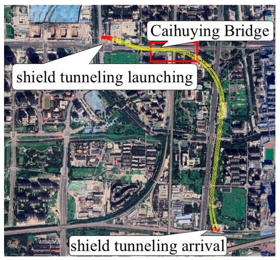
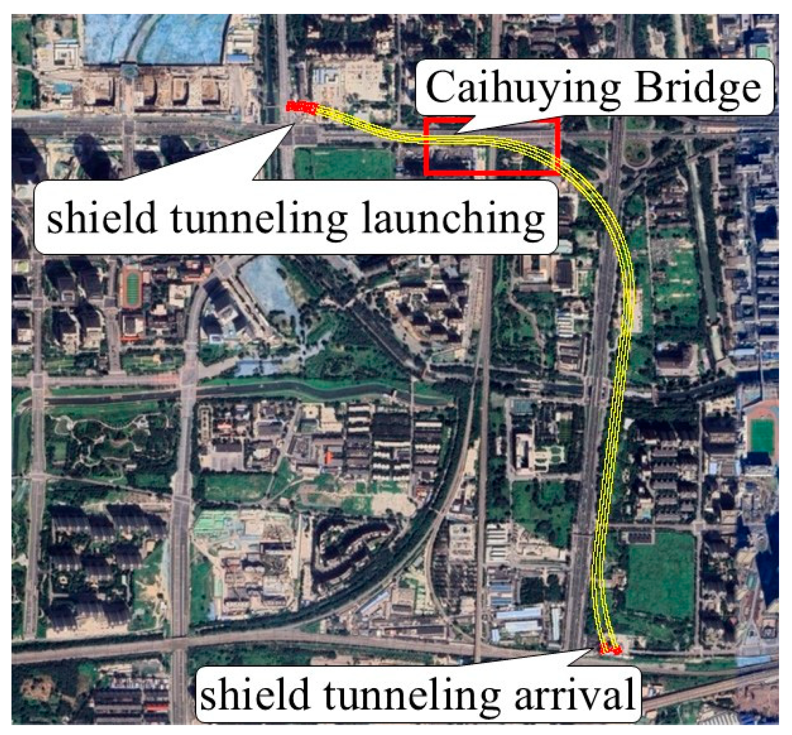
The Beijing Subway New Airport Extension Line extends from the Lize Financial Business District in the north to Caoqiao Station in the south, with its main alignment covering chainage K46+383.508 to K43+925.241. The line sequentially passes through Caihuying Bridge, Caihuying Station of Metro Line 14, and the Beijing-Kowloon Railway. The project schematic is shown in Figure 1.
Figure 1.
Route diagram of Beijing Subway New Airport Extension Line.
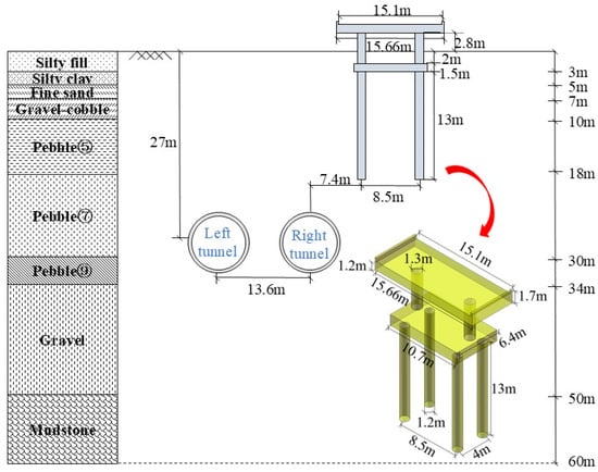
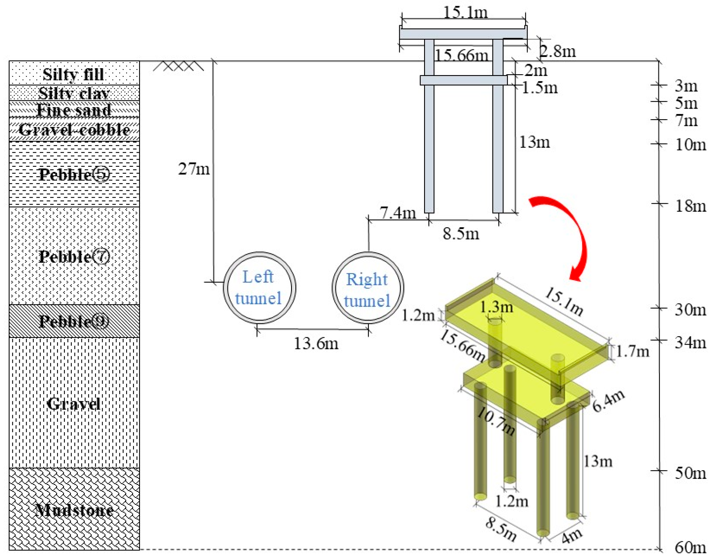
The burial depth of the twin shield tunnels ranges from approximately 19.90 m to 35.70 m, with a small clearance of 4.8 m. The ring width of the lining is 1.6 m, with an outer diameter of 8.8 m and an inner diameter of 7.9 m. The geological profile is shown in Figure 2. From top to bottom, the ground strata are composed of the following layers: silty fill, silty clay, silty fine sand, gravel-cobble, pebble ⑤, pebble ⑦, pebble ⑨, gravel, and mudstone layers. The twin tunnels in this section have a burial depth of approximately 27 m, while the tunnel structure is mainly located within the pebble ⑦ and pebble ⑨ layers.
Figure 2.
Geological cross-section of the New Airport Extension Line Section side-crossing the Bridge Pile.
Within this section, the twin tunnels closely side-cross Piles #0–#9 of the Caihuying Bridge. The horizontal clear distance between the tunnel and the pile tips ranges from approximately 2.337 m to 19.491 m, while the vertical clearance ranges from 0.079 m to 5.882 m. The associated construction risk is assessed as Level 1. A detailed analysis is carried out on Pile #0, which is the nearest pile foundation to the twin tunnels. As shown in Figure 2, Pile #0 consists of a 2 × 2 pile group, with a diameter of 1.2 m and a length of 13 m. The bridge pier above the pile cap has a diameter of 1.3 m and protrudes 2.8 m above the ground surface. Pile #0 is located approximately 6.7 m from the centerline of the right tunnel, with a pile spacing of 8.5 m.
3. Finite Element Numerical Simulations
3.1. Model Establishment
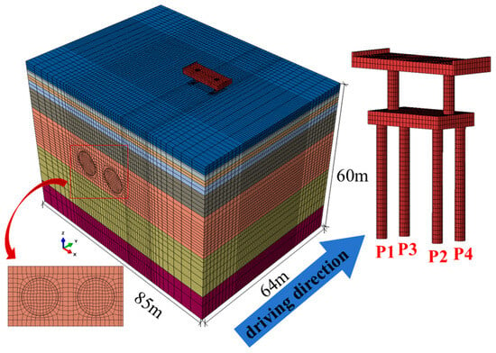
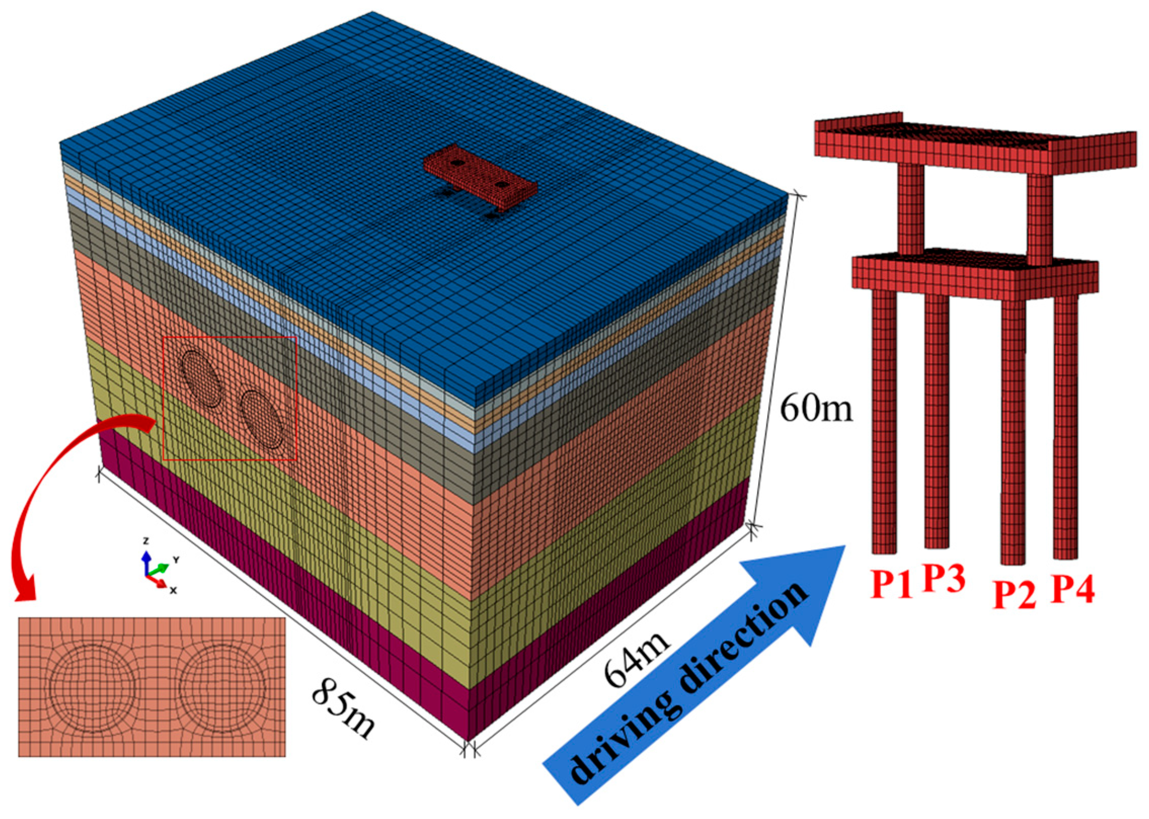
A three-dimensional finite element model for tunnel-pile group interaction was established, with its geometric and geological parameters based on the Beijing Subway New Airport Extension Line project. To eliminate boundary effects, the model’s lateral boundaries were set at least three times the tunnel diameter from the tunnel centerline. The model dimensions were set to 85 m × 60 m × 64 m, with the mesh configuration shown in Figure 3. The mesh consists of 169,332 elements and 168,658 nodes. To achieve a balance between computational efficiency and accuracy, refined meshes are adopted for the key areas near the tunnels and pile group, whereas coarser meshes are used for the surrounding areas [38]. The pile-soil interface is modeled using surface-to-surface contact pairs. The normal contact behavior is defined as hard contact, which permits interface separation under tensile stress conditions. The tangential behavior is characterized by the penalty friction formulation with a friction coefficient of 0.3. The model is constrained as follows: normal displacements are fixed on the four lateral boundaries, the bottom boundary is fully fixed, and the top surface remains traction-free.
Figure 3.
Schematic diagram of three-dimensional finite element model mesh generation.
The soil behavior is simulated using the Mohr-Coulomb elastoplastic constitutive model, and the influence of groundwater seepage is neglected in this analysis. Bridge pier, pile foundation, shield shell, grouting layer, and lining all employ linear elastic models, in which damage initiation and stiffness degradation are not taken into account [46]. Their material properties used in the analysis are given in Table 1 and Table 2.
Table 1.
Material properties of soils.
Table 2.
Material properties of bridge pile, grout, lining, and shield shell.
The construction procedure for the twin shield tunnels with small clearance is simulated in accordance with the actual on-site construction sequence, in which the left tunnel is excavated first, followed by the right tunnel. The specific steps are as follows:
- (a)
- Initial geostatic equilibrium is established, followed by the installation of the pile foundation.
- (b)
- Then the left tunnel is excavated in 1.6 m increments (one ring), with a tunnel face pressure of 200 kPa.
- (c)
- The lining and grouting layers are installed with a lag of seven rings behind the excavation face. A grouting pressure of 250 kPa is simultaneously applied to both the surrounding soil and the lining.
- (d)
- The hardening process of the grouting layer is subsequently simulated by increasing its elastic modulus from 20 MPa to 400 MPa.
- (e)
- The right tunnel is excavated following the same simulation steps.
3.2. Verification of Numerical Model
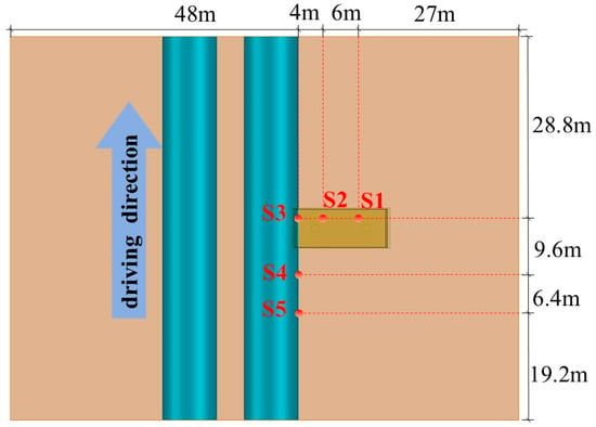
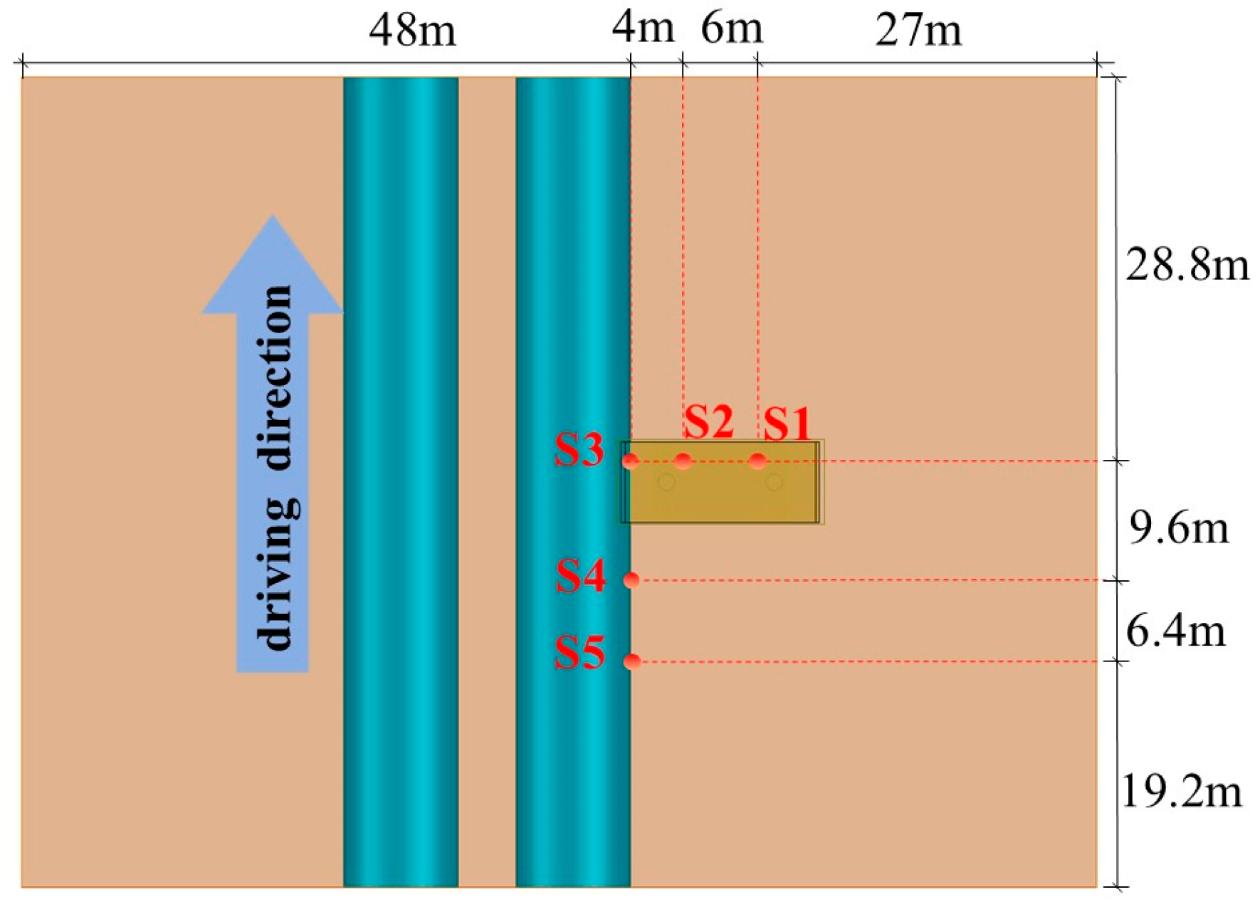
To verify the validity of the numerical model, surface settlements were monitored during the construction of the twin tunnels. The layout of the monitoring points is illustrated in Figure 4.
Figure 4.
Layout of monitoring point.
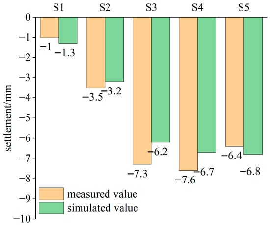
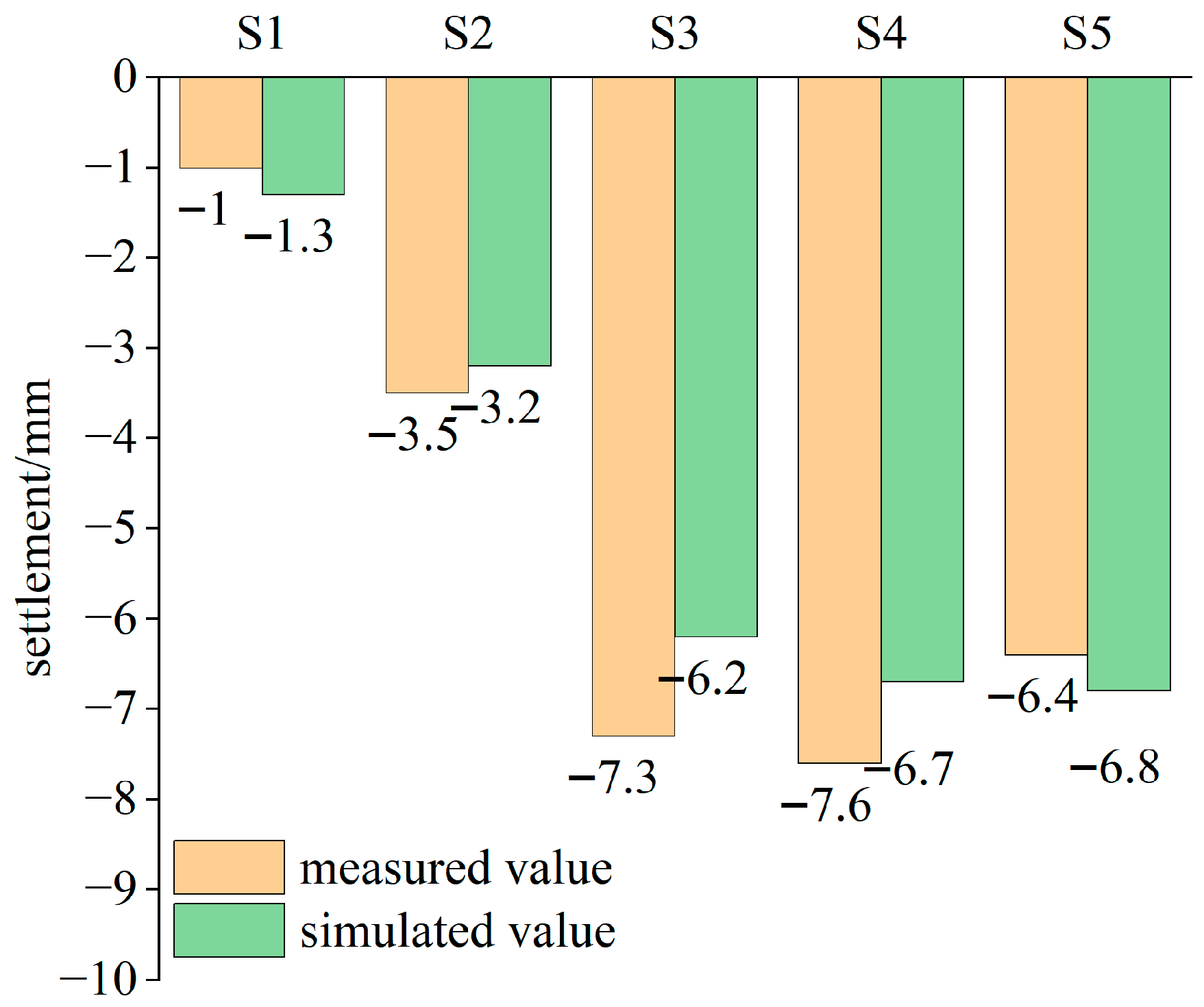
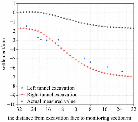
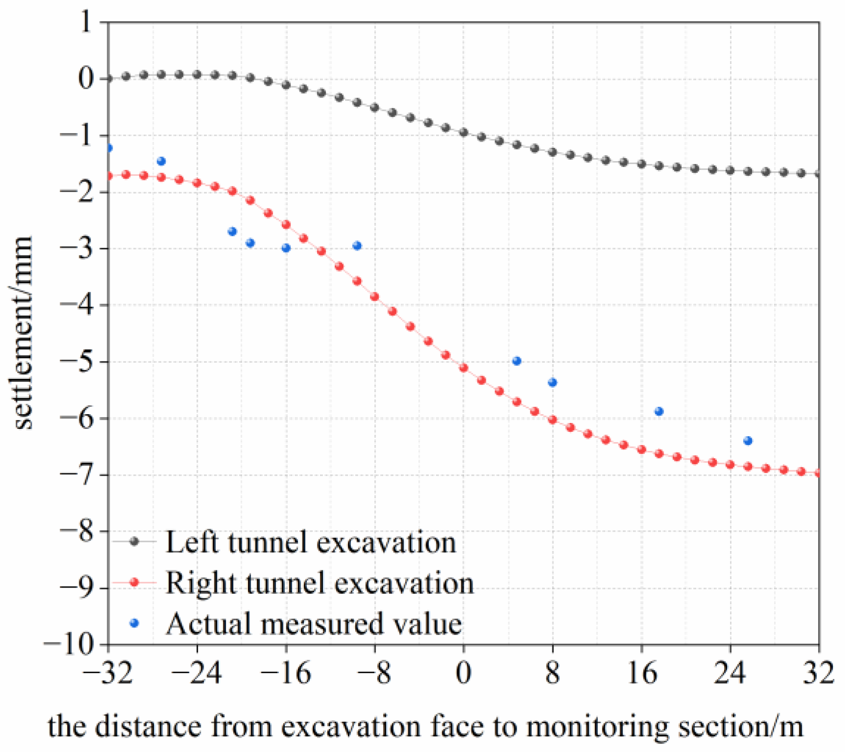
Considering the actual excavation process, a comparison of the surface settlements is conducted between the field monitoring results (the right tunnel advanced to the 209th ring) and numerical simulation results (the right tunnel advanced to the 36th ring). As shown in Figure 5 and Table 3, surface settlements increase towards the centerline of the right tunnel. For monitoring points S1 to S5, the absolute error between the simulated and measured values ranges from 0.3 mm to 1.1 mm. The maximum relative error at point S1 is 30%, which is primarily attributable to the extremely small absolute settlement at that point (only 1 mm). Furthermore, the absolute error at that point is only 0.3 mm with negligible actual deviation. The relative error of monitoring points S2–S5 with significant settlement is controlled within 15.1%, which fully satisfies the accuracy requirements of geotechnical engineering numerical simulation. Figure 6 shows the settlement trend during the twin-tunnel excavation. As the shield face advances towards monitoring point S5, the vertical displacement at the monitoring point exhibits a trend of initial slow settlement, followed by accelerated settlement and subsequent stabilization. The difference between the calculated vertical displacement value and the actual monitoring result at monitoring point S5 is within 1 mm. Overall, the calculated values at each monitoring point are in good agreement with the actual measured values.
Figure 5.
Comparison of actual and simulated settlement values at monitoring points S1–S5.
Table 3.
Absolute error and Relative error at monitoring points S1–S5.
Figure 6.
Comparison of actual and simulated settlement values at monitoring point S5.
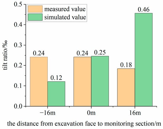
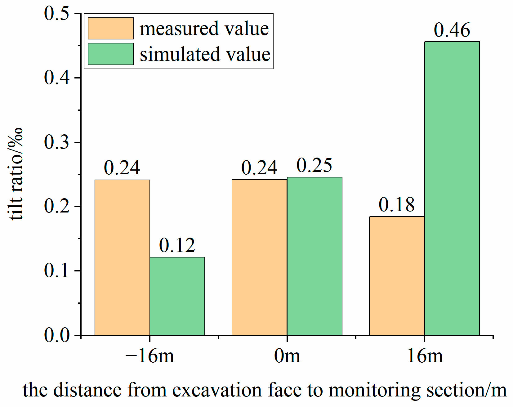
Figure 7 compares the measured and numerically simulated tilt ratios of the bridge pier above P 1 during the right-tunnel excavation. When the excavation face is 16 m away from the bridge pier, the measured tilt ratio is 0.24‰ and the simulated value is 0.12‰, which are relatively close. When the shield machine advances to the bridge pier section, the measured and simulated tilt ratios are 0.24‰ and 0.25‰, respectively, showing excellent agreement. When the shield machine has advanced 16 m beyond the bridge pier section, the measured tilt ratio is 0.18‰, whereas the corresponding numerical prediction is 0.46‰. Since the inclination rate is expressed in parts per thousand (‰) with an extremely small magnitude, the relative discrepancy is inherently amplified to a certain extent. Overall, the simulated results are in good agreement with the measured values, which can meet the analytical requirements of this study.
Figure 7.
Comparison of actual and simulated tilt ratio at bridge pier above P 1.
3.3. Analysis of Numerical Computation Results
3.3.1. Strata Response
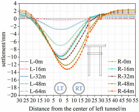
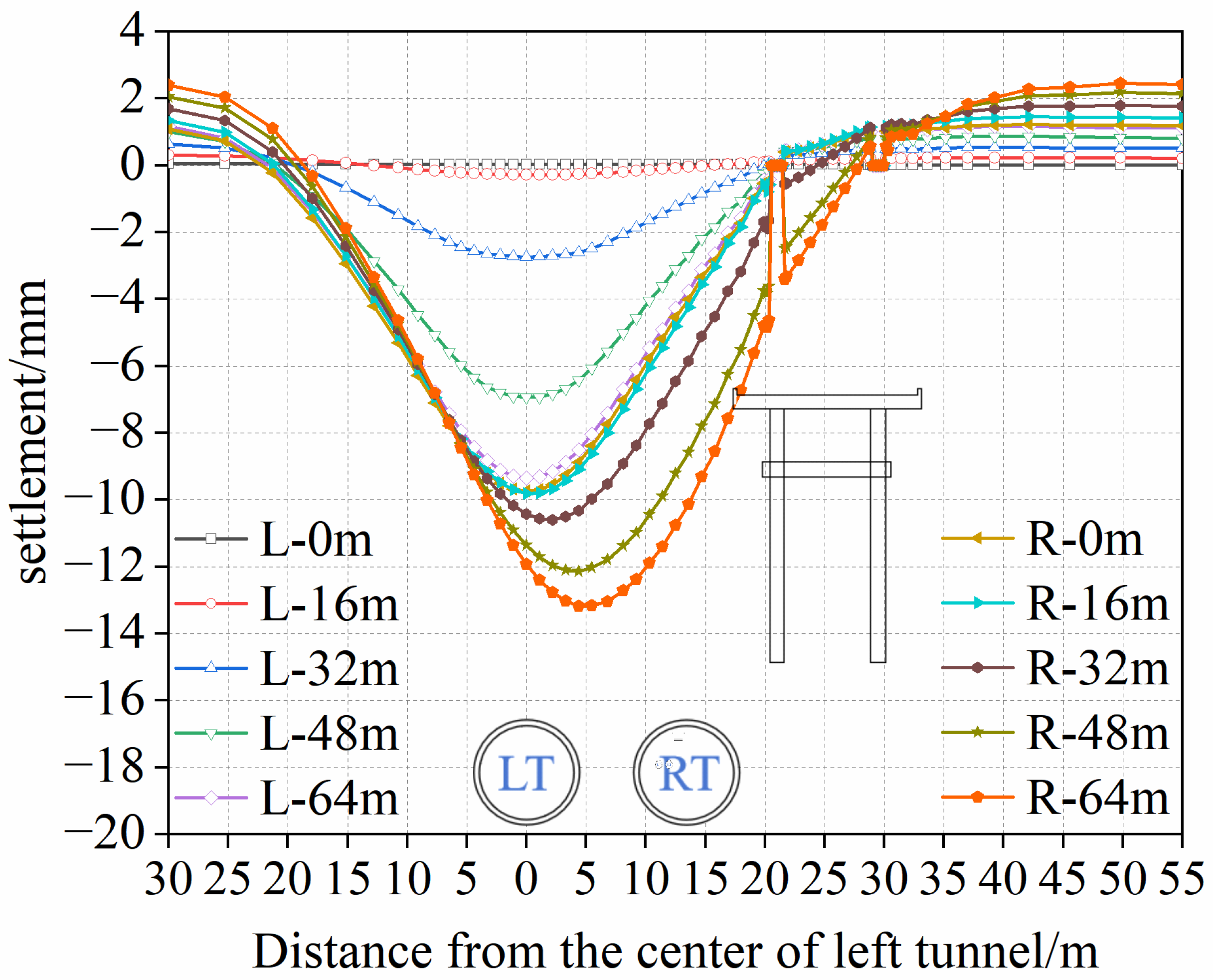
Through the comparative analysis above, the validity and reliability of the established numerical model have been verified. The responses of the strata and the pile group during the twin-tunnel construction are analyzed in this section. The monitoring section was selected at y = 32 m. The surface settlement values at the monitoring section were recorded every 10 rings (16 m in width) during the entire construction process. The time-history curves of surface settlement at the monitoring section are shown in Figure 8. In this figure, LT and RT denote the left tunnel and right tunnel, respectively; L-XX m and R-XX m represent the advance distance during the excavation of the left tunnel and right tunnel, respectively.
Figure 8.
Surface settlement at monitoring section.
As illustrated in Figure 8, during the left tunnel excavation, the surface settlement at the monitoring section exhibits an approximately symmetric distribution with respect to the vertical centerline of the left tunnel. The surface settlement increases as the distance to the vertical centerline of the left tunnel decreases. At the initial stage of the left tunnel excavation (at y = 0 m), the ground surface above the twin tunnels exhibited almost no deformation. As the shield face approached within 16 m of the monitoring section, a noticeable increase in surface settlement was observed. When the shield face advanced to the monitoring section (y = 32 m), surface settlement increased rapidly, with a maximum value of 2.8 mm. After the shield face advanced approximately 16 m past the monitoring section, the rate of surface settlement slowed down significantly. Following the completion of the left tunnel excavation, surface settlement at the monitoring section stabilized, with a maximum value of 9.4 mm. Upon initiation of the right tunnel excavation, the location of the maximum surface settlement gradually shifted toward the right tunnel, with a maximum value of 13.5 mm.
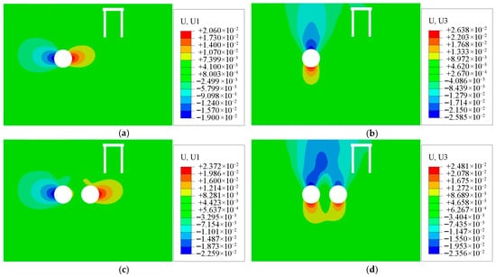
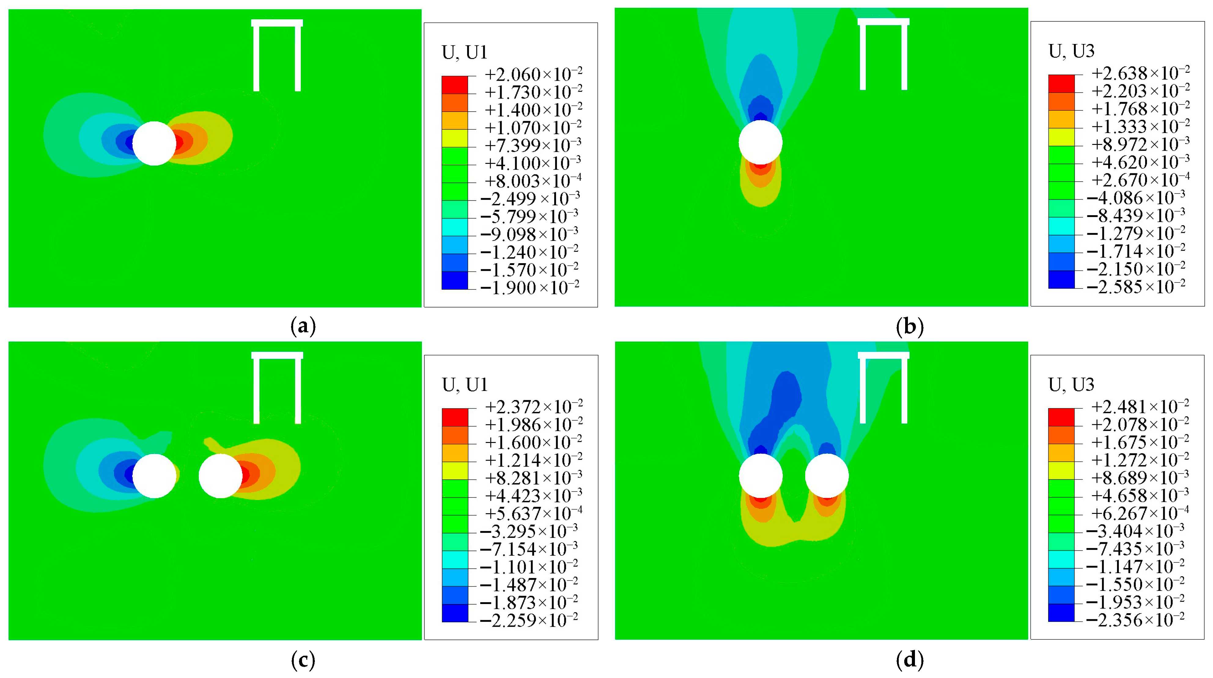
Following the completion of the twin-tunnel excavation, displacement contour diagrams of the strata were extracted and analyzed from another section at y = 30 m, as shown in Figure 9. After the left tunnel was completed, settlement of the tunnel crown was recorded, with a maximum value of 25.8 mm. The tunnel invert zone exhibited significant heave, with a maximum value of 26.3 mm. The tunnel excavation induced lateral ground displacement toward the outside of the tunnels on both sides, with a maximum value of 20.6 mm. After the right tunnel was completed, both the vertical and lateral displacements of the surrounding soil increased significantly, with maximum values of 24.8 mm and 23.7 mm, respectively.
Figure 9.
Displacement contour diagram of the strata: (a) Lateral displacement after the left tunnel excavation was completed; (b) Vertical displacement after the left tunnel excavation was completed; (c) Lateral displacement after the right tunnel excavation was completed; (d) Vertical displacement after the right tunnel excavation was completed (unit: m).
3.3.2. Pile Group Deformation Response
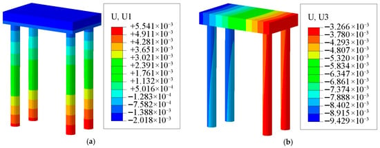
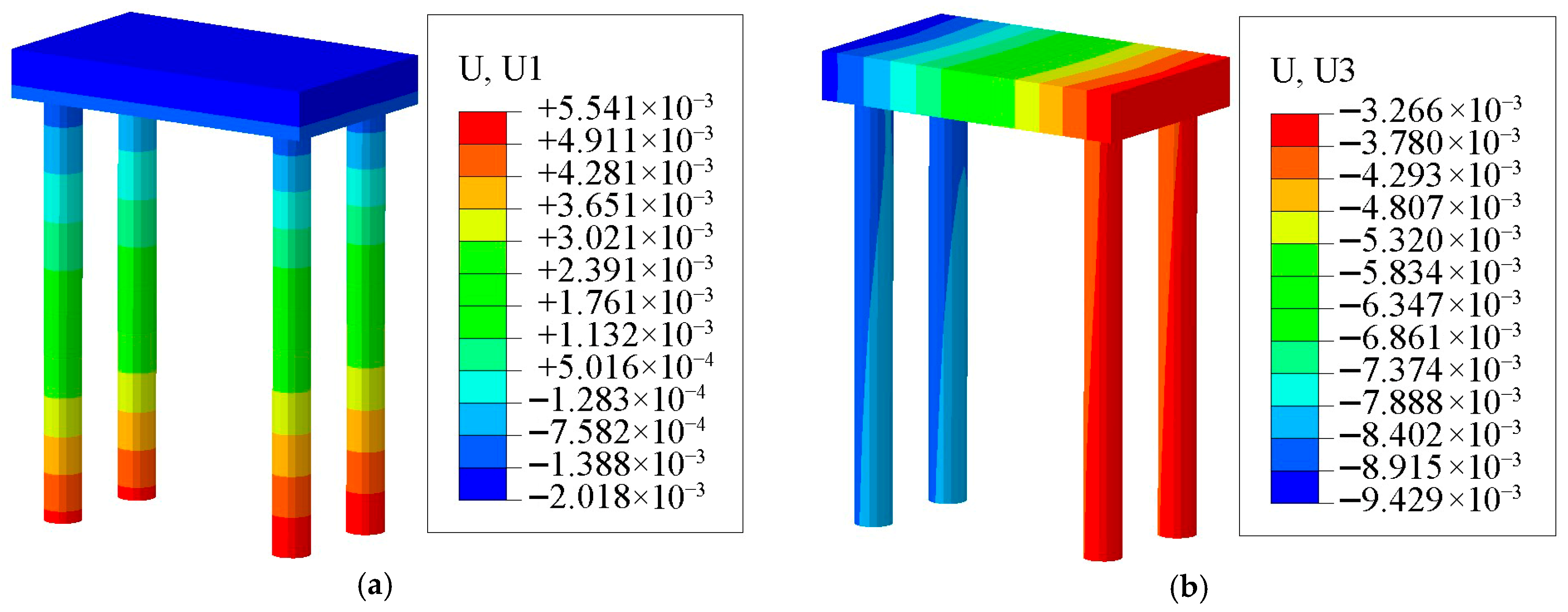
Figure 10 illustrates the final displacement contour diagrams of the pile foundation. In Figure 10a, negative values denote lateral displacement toward the tunnel, whereas positive values denote displacement away from it. In Figure 10b, the vertical displacement on the left side of the pile foundation is significantly greater than that on the right side. As a result, the pile foundation exhibits an overall tendency of tilting toward the tunnel side. The deformation characteristics of the near piles P 1 and P 3 are similar, while those of the far piles P 2 and P 4 are similar. This indicates that the piles exhibit consistent responses at similar spatial locations. Therefore, the near pile P 1 and far pile P 2 were selected for a detailed analysis of the lateral and vertical displacements. Hereafter, P 1 and P 2 are used to represent the near pile P 1 and far pile P 2, respectively.
Figure 10.
Displacement contour diagrams of the pile foundation: (a) Lateral displacement; (b) Vertical displacement.
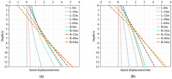
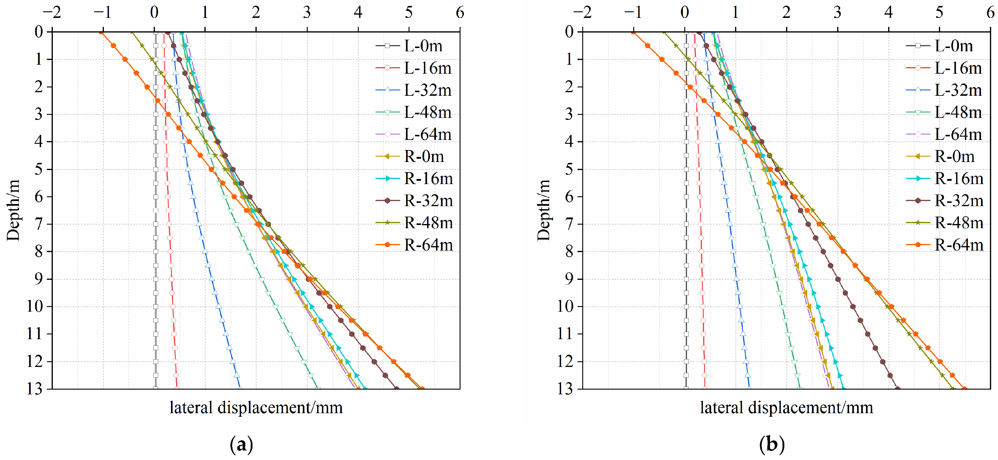
The lateral displacement trends of P 1 and P 2 during the twin-tunnel excavation are shown in Figure 11. During the progress of the left tunnel excavation, the pile foundation had a tendency to shift away from the twin tunnels. The lateral displacement subsequently increased along the pile shafts. Lateral displacements induced by left tunnel excavation reached peak values at the pile tips, approximately 4 mm for P 1 and 3 mm for P 2. Excavation of the right tunnel induced the upper segments of the piles to deflect toward the tunnel, resulting in a continuous inclination of the entire pile foundation. This resulted in final lateral displacements at the pile tips of 5.3 mm for P 1 and 5.5 mm for P 2, representing increases of 32.5% and 83.3%, respectively. This phenomenon is attributed to soil unloading adjacent to the pile group, which reduces the normal and tangential friction resistances and further induces additional lateral deformation of the pile shaft.
Figure 11.
Lateral displacements of pile shafts: (a) P 1; (b) P 2.
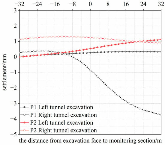
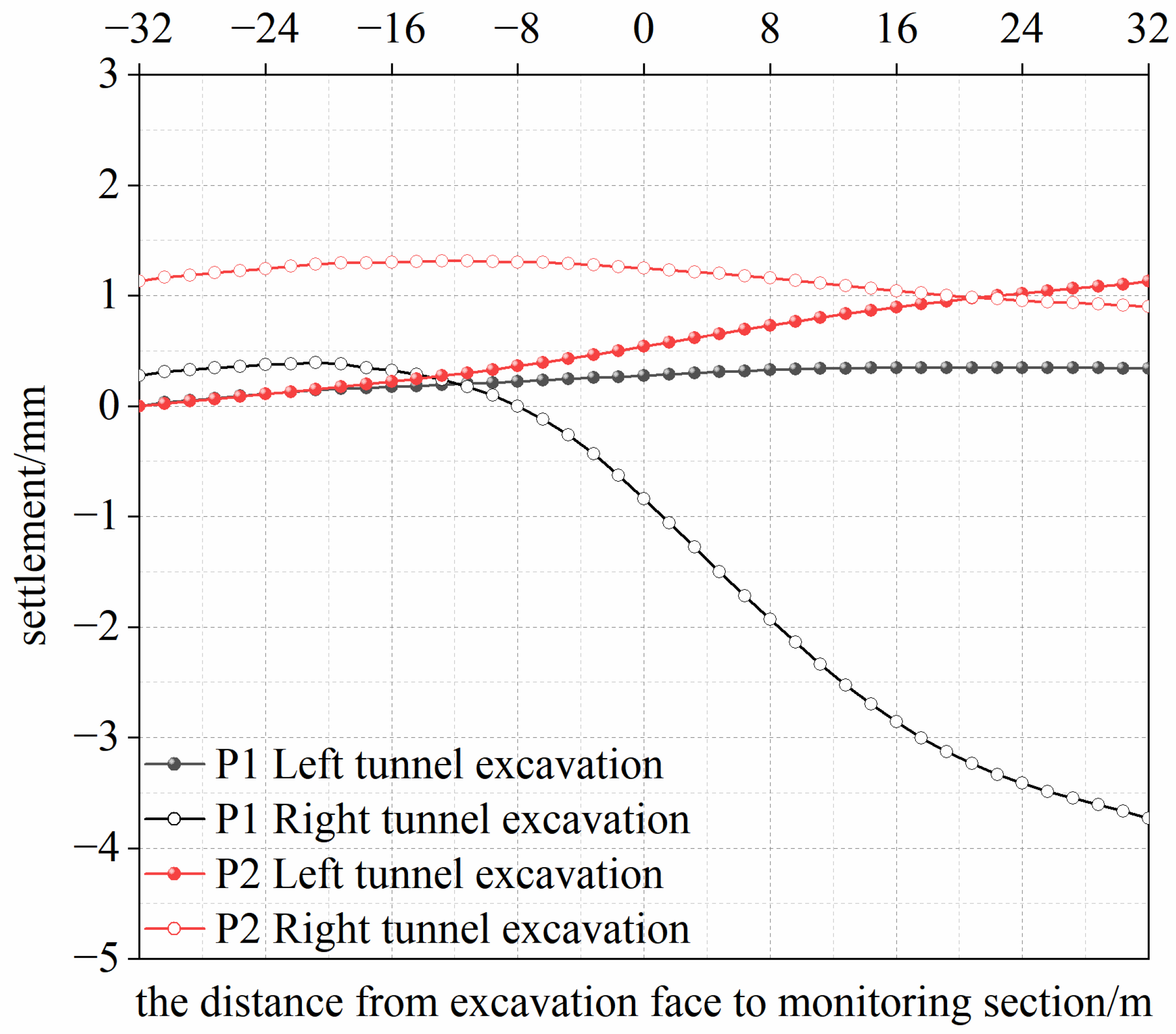
The vertical displacement curves of P 1 and P 2 at the pile tops during the twin-tunnels excavation are shown in Figure 12. The left tunnel excavation had a negligible effect on the vertical response of the pile foundation, with a maximum recorded heave of less than 1 mm. Upon entering the right tunnel excavation stage, the pile foundation exhibited continuous slight heave. When the shield face approached within 20 m of the monitoring section, P 1 exhibited a rapid settlement trend, with a final settlement of 3.8 mm. The heave of P 2 gradually decreased, with the final heave value of 1 mm. Based on the above analysis, the results indicate that the primary influence zone of the tunnel excavation on the vertical displacement of the pile foundation is limited to within twice the tunnel diameter. For P 1, the settlement within this range accounts for 75% of the total settlement value during the right tunnel excavation. Furthermore, the vertical displacement of P 2 remained within 0–1.5 mm throughout the twin-tunnel excavation. The results demonstrate that the influence of tunnel excavation on pile displacement decreases markedly with increasing tunnel-pile distance.
Figure 12.
Trend of vertical displacement at pile top.
3.3.3. Additional Axial Force and Bending Moment of Pile Group
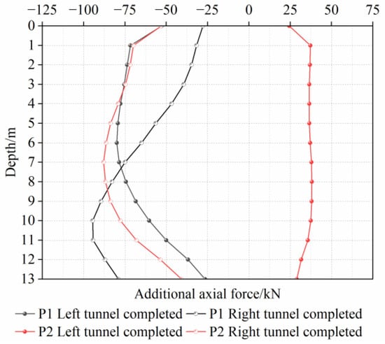
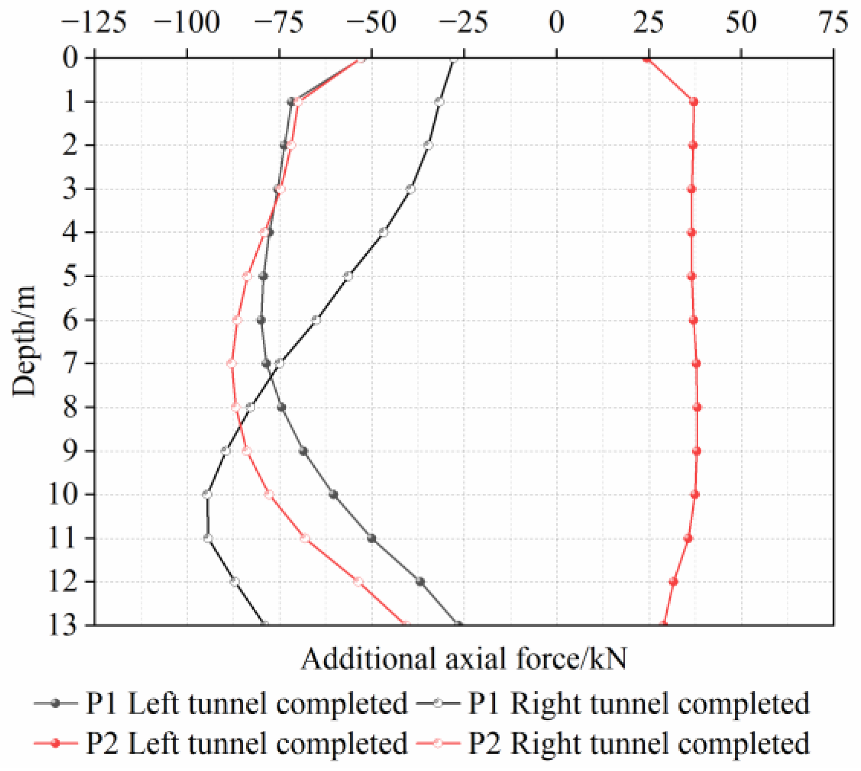
Taking the P 1 and P 2 as representative piles, their additional axial forces and bending moments are shown in Figure 13. Shield tunnel excavation disturbs the soil surrounding the pile group, thereby inducing additional axial forces along the pile shafts. For P 1, the downward displacement of the surrounding soil relative to the pile group mobilized negative skin friction, thereby increasing the axial force on the pile shaft. The additional axial force on P 1 first increased and then decreased along the pile shaft, with a maximum value of 80 kN after the left tunnel excavation was completed. Upon completion of the right tunnel, the soil around the lower segment of P 1 was significantly disturbed, leading to a notable increase in the additional axial force on this segment of P 1, with a maximum value of 95 kN. For P 2, upward soil movement relative to pile shaft induced positive skin friction during the left tunnel excavation, resulting in a positive additional axial force. Upon completion of the right tunnel, the additional axial force reversed its direction, with a maximum additional axial force of 88 kN.
Figure 13.
Additional axial forces.
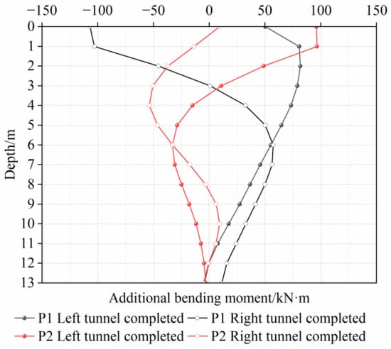
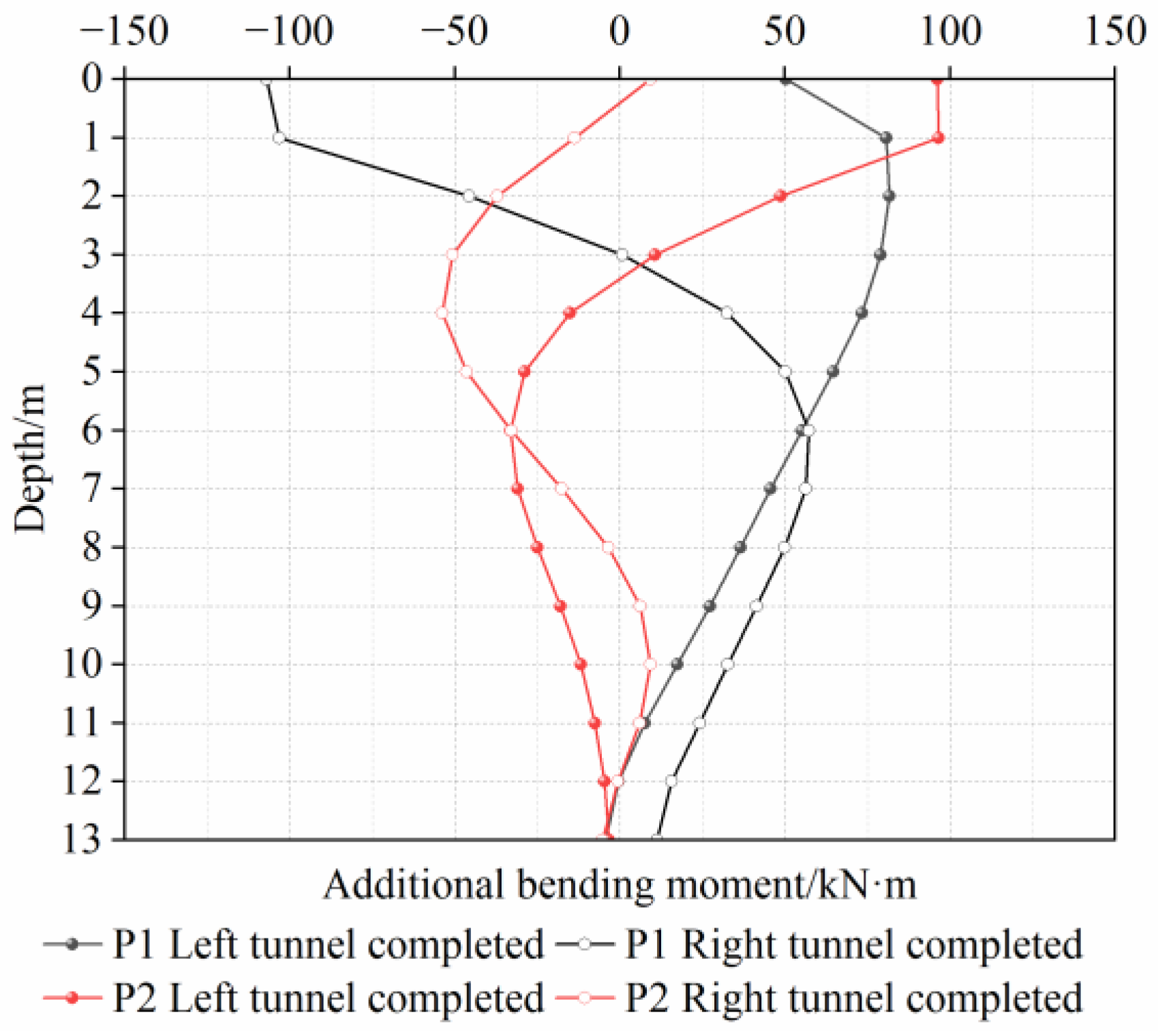
The additional bending moments on the pile shafts of P 1 and P 2 are shown in Figure 14. Following the completion of the left tunnel excavation, the pile group exhibited additional bending moments, which gradually decreased along the pile shafts. The maximum additional bending moments of P 1 and P 2, which occurred near the connection between the pile cap and pile shafts, were 81.8 kN·m and 96.6 kN·m, respectively. Upon completion of the right tunnel, the additional bending moment in the upper segment of P 1 exhibited a reversal and increased to a maximum value of 107.1 kN·m. Meanwhile, the additional bending moment in the lower segment increased to varying degrees. The additional bending moment of P 2 exhibits an “S” shaped distribution along the pile shaft, with a maximum value of 53.9 kN·m.
Figure 14.
Additional bending moments.
4. Results and Discussion
Based on the actual project, the above section has analyzed the response mechanisms induced by the construction of the twin tunnels with small clearance on the surrounding strata and pile group. To further investigate the influence of various factors on the strata and existing pile foundations during the excavation of the twin tunnels with small clearance, a detailed study was conducted from the aspects of pile foundation types, construction sequences, and shield tunneling parameters. The findings are intended to provide guidance for similar twin-tunnel projects in Beijing’s pebble strata.
4.1. Pile Length
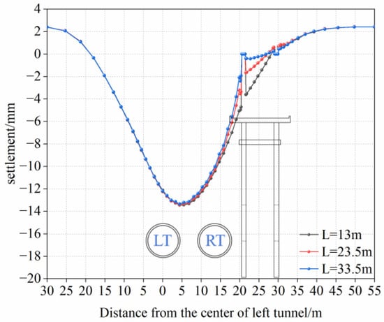
To investigate the influence of pile length on the response of twin tunnels with small clearance, based on the numerical model established previously, this section adopts different relative positions between the tunnel and pile tip, with all other parameters held constant. Three cases are designed based on the pile tip location relative to the tunnel:
- (a)
- the pile tip is located above the tunnel, represented by Pile #0, with a pile length of 13 m (short pile);
- (b)
- the pile tip is located at the tunnel centerline, with a length of 23.5 m (medium pile);
- (c)
- the pile tip is located below the tunnel, with a length of 33.5 m (long pile).
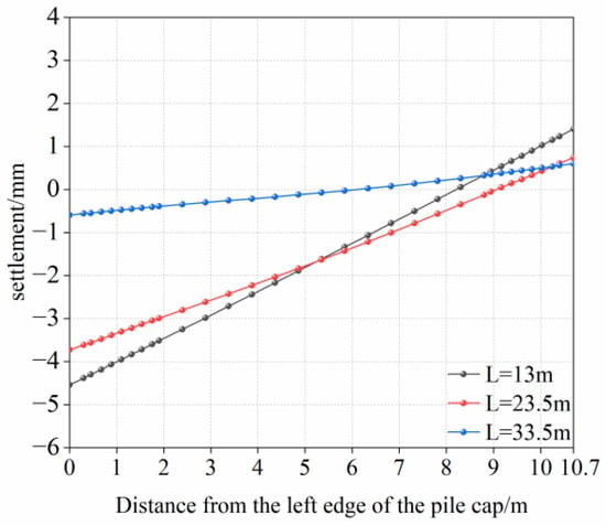
The surface settlement curves at the monitoring section under different pile lengths are shown in Figure 15. The results indicate that the influence zone for the vertical displacement of the surrounding soil is primarily confined above the pile cap. As can be seen from the pile cap settlement value shown in Figure 16, the vertical displacement of the pile foundation decreases substantially with increasing pile length. Longer piles, being embedded in deeper and more stable soil strata, exhibit higher bearing capacity and deformation resistance, thereby effectively reducing pile inclination.
Figure 15.
Surface settlement under different pile lengths.
Figure 16.
Vertical displacement of pile caps under different pile lengths.
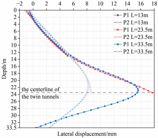
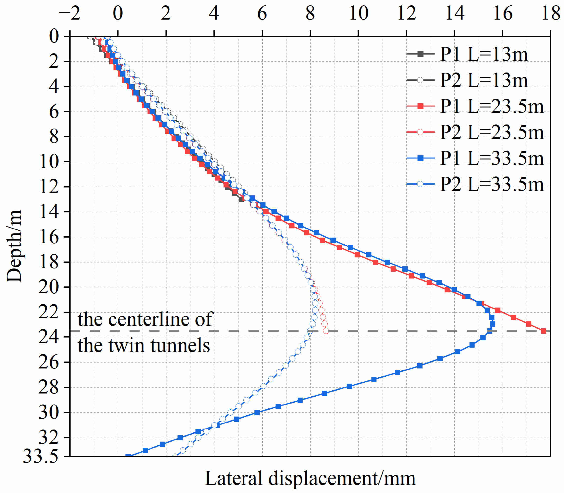
The lateral displacements of the pile shafts under different pile lengths are shown in Figure 17. For short and medium piles, the lateral displacements along the pile shafts are characterized by a nearly linear increase. For long piles, the lateral displacements of the pile shafts exhibit an initial increase followed by a decrease, with the peak values occurring at the tunnel centerline, which is consistent with existing studies [3,37,39]. This phenomenon is mainly attributed to the most severe disturbance of the soil around the tunnel induced by shield tunneling, as well as the effects of strata loss above the tunnel and unloading rebound of the soil below the tunnel [2,30]. For medium and long piles, the maximum lateral displacements of P 1 are 17.7 mm and 15.6 mm, respectively. With an increase in the tunnel-pile spacing, compared with P 1, P 2 exhibit correspondingly lower lateral displacement values of 8.8 mm and 8 mm, respectively. In addition, the maximum lateral displacement of long piles is generally smaller than that of medium piles. This is mainly because long piles extend into the gravel layer, with their pile tips embedded in the gravel layer less affected by tunneling, which effectively reduces the maximum lateral displacement [47].
Figure 17.
Lateral displacements of pile shafts under different pile lengths.
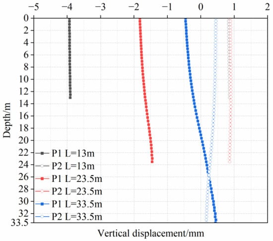
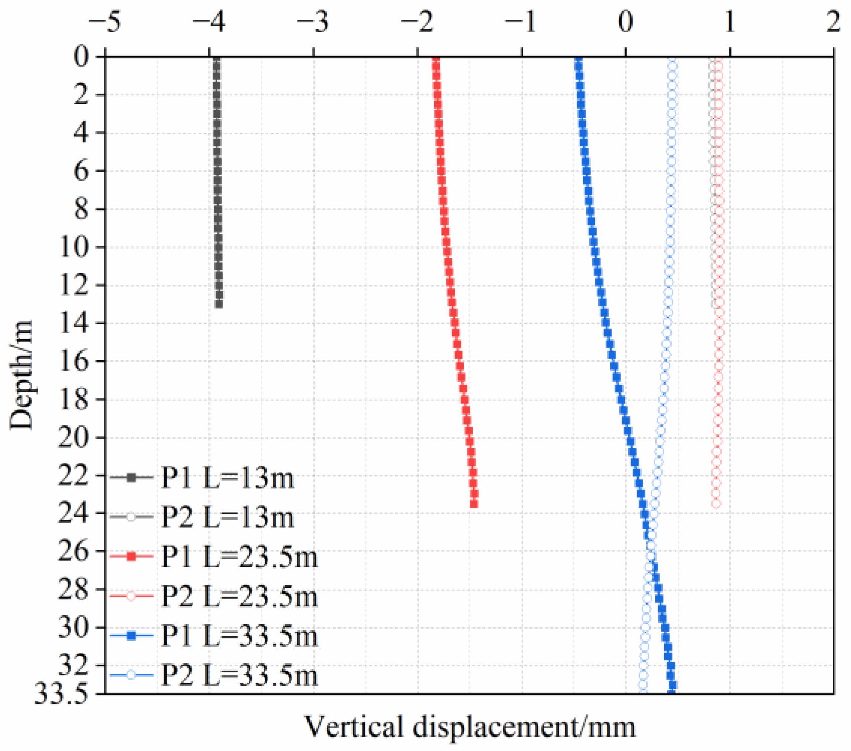
The vertical displacements of P 1 and P 2 under different pile lengths are shown in Figure 18. As the embedded depth of the pile foundation increases, longer piles generate greater total frictional resistance, resulting in a decrease in the overall vertical displacements of the pile shafts [47]. This indicates that the pile length is one of the key factors in controlling the vertical displacement of pile foundation induced by adjacent tunneling. For medium and long piles, the maximum vertical displacements of P 1 are located at the pile tops, with the maximum values of 1.8 mm and 0.5 mm, respectively. Compared with the short pile (with a maximum vertical displacement of 4 mm), the maximum values decrease by 55% and 87.5%, respectively. In contrast, the corresponding displacements at the pile top of P 2 exhibit negligible variation under different pile lengths.
Figure 18.
Vertical displacements of pile shafts under different pile lengths.
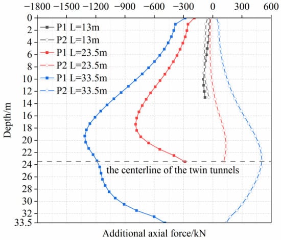
The additional axial forces of the pile shafts of different pile lengths are shown in Figure 19. The relative position between the pile tip and the twin tunnels exerts a significant influence on the axial forces of pile shafts. The skin frictional resistance of short piles is more fully mobilized, resulting in a smaller additional axial force along the pile shafts. The additional axial forces of medium and long piles show a similar trend: they increase initially and then decrease along the pile shafts. The maximum additional axial forces of P 1 are 792 kN and 1314 kN, respectively, located at the tunnel crown. The maximum additional axial forces of P 2 are 136 kN and 500 kN, respectively. The longer the pile shaft, the greater the absolute value of the additional axial force at the same horizontal elevation. This also demonstrates that the skin friction of long piles is mobilized to a lesser extent than that of short piles, which is consistent with the trend that pile foundation settlement decreases with increasing pile length.
Figure 19.
Additional axial forces of pile shafts under different pile lengths.
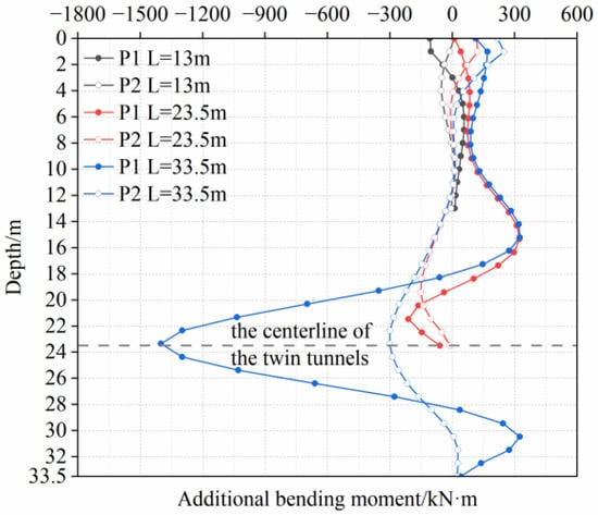
The additional bending moments and their maximum values of the pile shafts under different pile lengths are shown in Figure 20 and Table 4. The condition for short piles is detailed in the preceding section. The medium and long piles exhibit similar variation patterns in additional bending moment. For P 1, the maximum positive additional bending moments are located at a depth of 15.3 m, with values of 322 kN·m and 325 kN·m, respectively. These values are approximately six times those of the short pile P 1. The maximum negative additional bending moments are 211.3 kN·m (at 2 m above the tunnel centerline) and 1400 kN·m (at the tunnel centerline), which are about twice and 14 times that of the short pile, respectively. For P 2, the maximum positive additional bending moments are located at the pile top, with values of 121.8 kN·m and 248.2 kN·m, respectively—approximately 13 times and 25 times that of the short pile P 2. The maximum negative additional bending moments are 152.8 kN·m (medium pile, at the tunnel crown) and 301.7 kN·m (long pile, at the tunnel centerline), which are about 3 times and 6 times that of the short pile P 2, respectively. As pile length increases, the maximum additional bending moment rises and the location of the maximum additional bending moment shifts from above the tunnel crown to the tunnel centerline.
Figure 20.
Additional bending moments of pile shafts under different pile lengths.
Table 4.
Maximum additional bending moments on the pile shafts (unit: kN·m).
Based on the displacement and internal force response characteristics under different pile lengths, medium and long piles exhibit smaller vertical displacements but significantly greater lateral displacements and additional internal forces, whereas short piles show prominent vertical displacement and a relatively weak internal force response. In similar engineering practice, additional internal forces and lateral deformation should be strictly controlled for long piles, while vertical displacement should be monitored in real time for short piles to ensure the structural safety and stability of bridge pile foundations throughout tunnel construction.
4.2. Construction Sequence of the Twin Tunnels
Existing studies have primarily focused on the influence of the construction sequence of twin stacked tunnels on pile foundations [48,49,50], whereas relevant research on the construction sequence of parallel twin tunnels is insufficient [51]. The above three conditions were simulated and analyzed in accordance with the construction sequence of excavating the left tunnel first, followed by the right tunnel. To further investigate the interaction between twin-tunnel excavation with small clearance and pile group under different construction sequences, two additional conditions were introduced based on the pile length of the medium pile: “Excavating the right tunnel first, followed by the left tunnel” and “Synchronous excavation of the twin tunnels”.
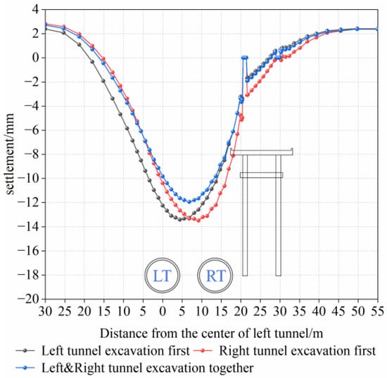
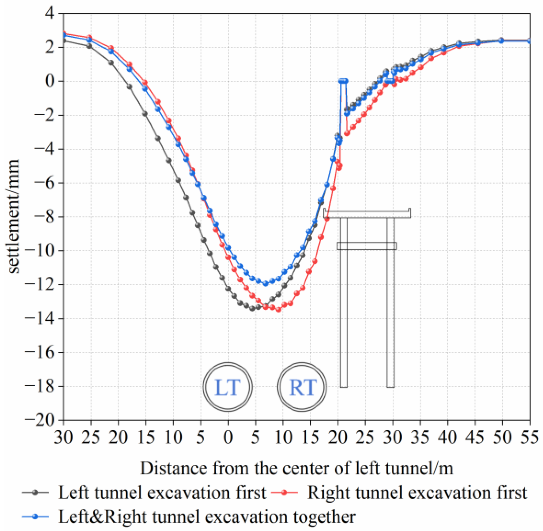
Select the monitoring section (y = 32 m) to plot the final surface settlement curve, as shown in Figure 21. For the asynchronous constructions, the maximum surface settlement values are nearly identical, with values of 13.4 mm. Under the condition of the synchronous twin-tunnel excavation, the maximum settlement point is located at the vertical centerline of the twin tunnels, with a maximum surface settlement value of 12 mm. This represents a reduction of approximately 10.4% compared to asynchronous constructions.
Figure 21.
Surface settlement at the monitoring section under different construction sequences.
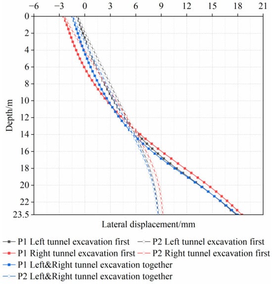
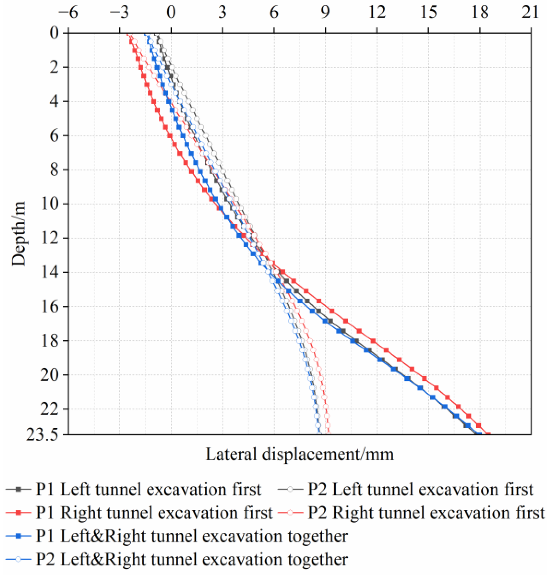
A comparison of pile lateral displacements for various construction sequences is illustrated in Figure 22. The lateral displacement curves of the pile shafts exhibit similar patterns under both the left-tunnel-first and synchronous twin-tunnel excavation conditions. When the right tunnel is excavated first, the lateral displacements of the pile shafts differ by less than 1 mm from the other two conditions, indicating that different construction sequences have a negligible effect on lateral pile response.
Figure 22.
Lateral displacements of pile shafts under different construction sequences.
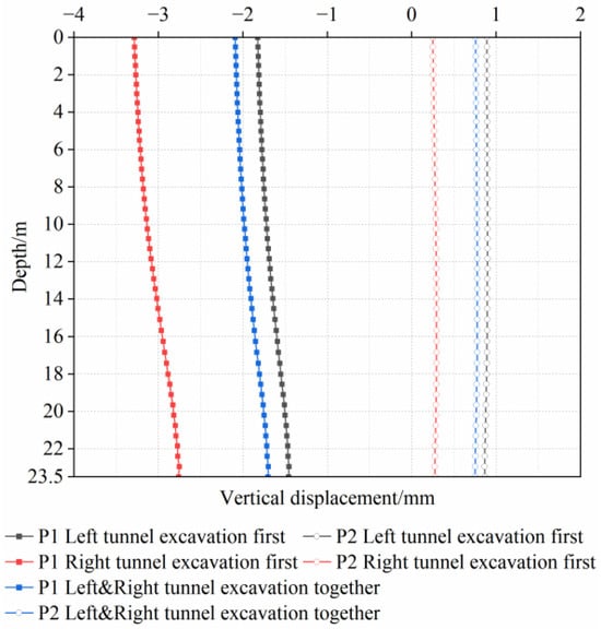
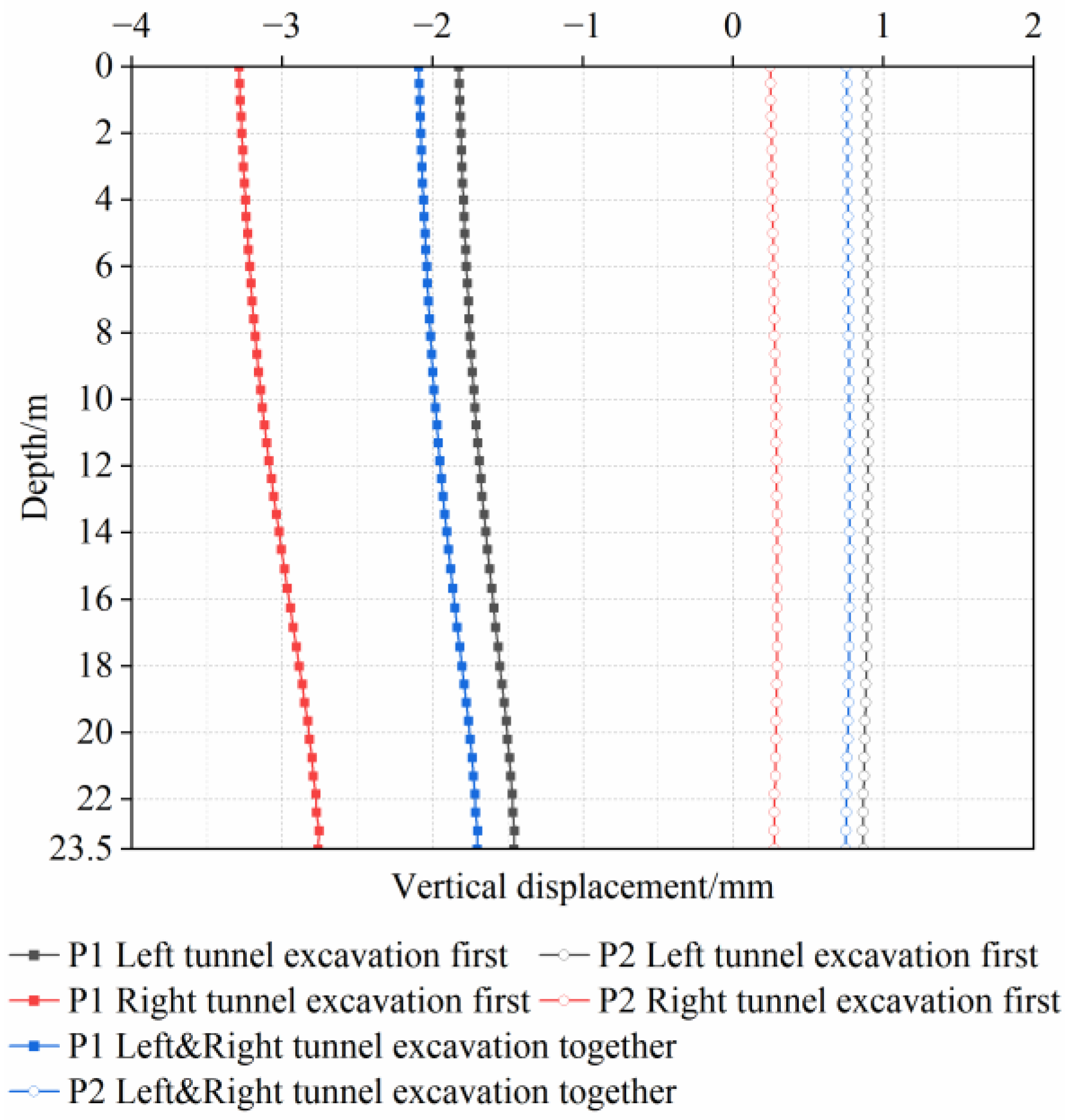
The vertical displacements of the pile shafts exhibit highly consistent trends across different construction sequences, as shown in Figure 23. From smallest to largest, the vertical displacements correspond to the following sequences: the left-tunnel-first excavation, the synchronous twin-tunnel excavation, and the right-tunnel-first excavation. Compared with previous studies [51], when the pile tip is located below the tunnel, the pile exhibits smaller vertical displacement when the tunnel closer to the pile foundation is excavated first. The maximum vertical displacements occur at the pile cap, with values of 1.8 mm, 2.1 mm, and 3.3 mm, respectively. For P 2, the entire pile shafts exhibit a heaving trend, with the maximum difference maintained within 1 mm.
Figure 23.
Vertical displacements of pile shafts under different construction sequences.
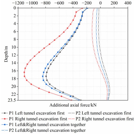
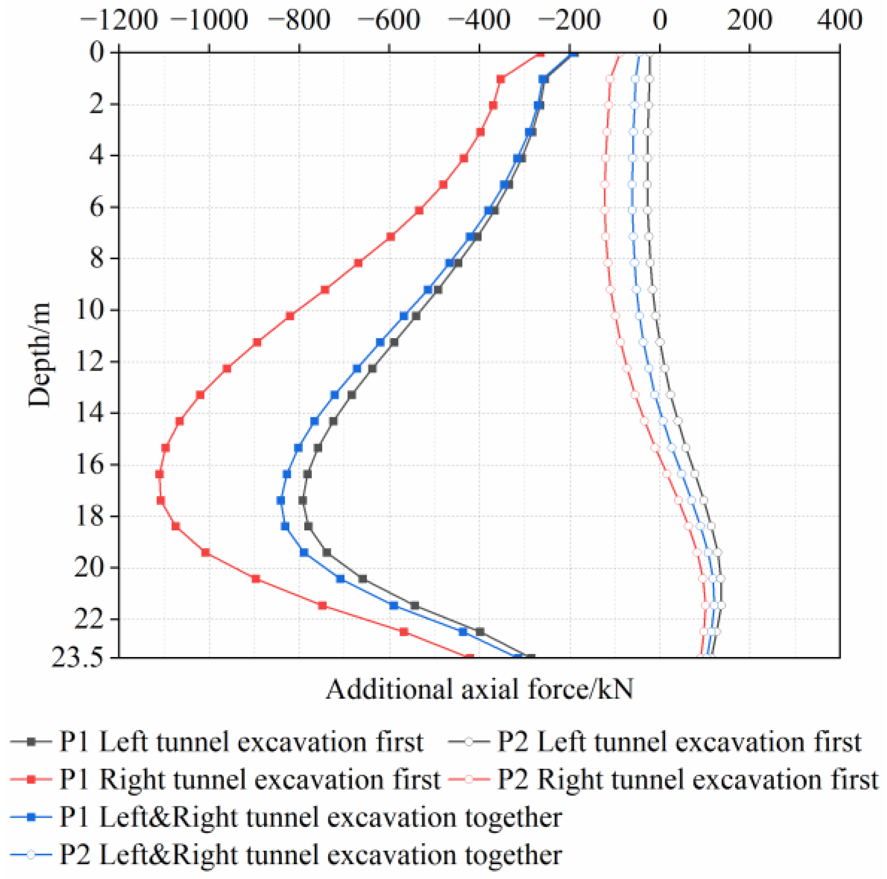
The pile shafts exhibit similar additional axial force characteristics under different construction sequences, as shown in Figure 24. For P 1, the additional axial forces increase initially and then decrease along the pile shafts. Under both left-tunnel-first and synchronous twin-tunnel excavation conditions, the difference in additional axial forces along the pile shafts is not significant. The maximum additional axial forces occur at a depth of 17.3 m, with values of 792.3 kN and 841.3 kN, respectively. When the right tunnel is excavated first, the additional axial force increases significantly. The point of maximum additional axial force occurs at a depth of 16.3 m, with a value of 1100 kN. Compared with the condition of the left-tunnel-first excavation, the additional axial force increases by approximately 38.8%. For P 2, the maximum values are positive, with values of 136.1 kN, 121 kN, and 101.5 kN, respectively.
Figure 24.
Additional axial forces of pile shafts under different construction sequences.
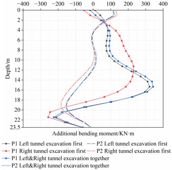
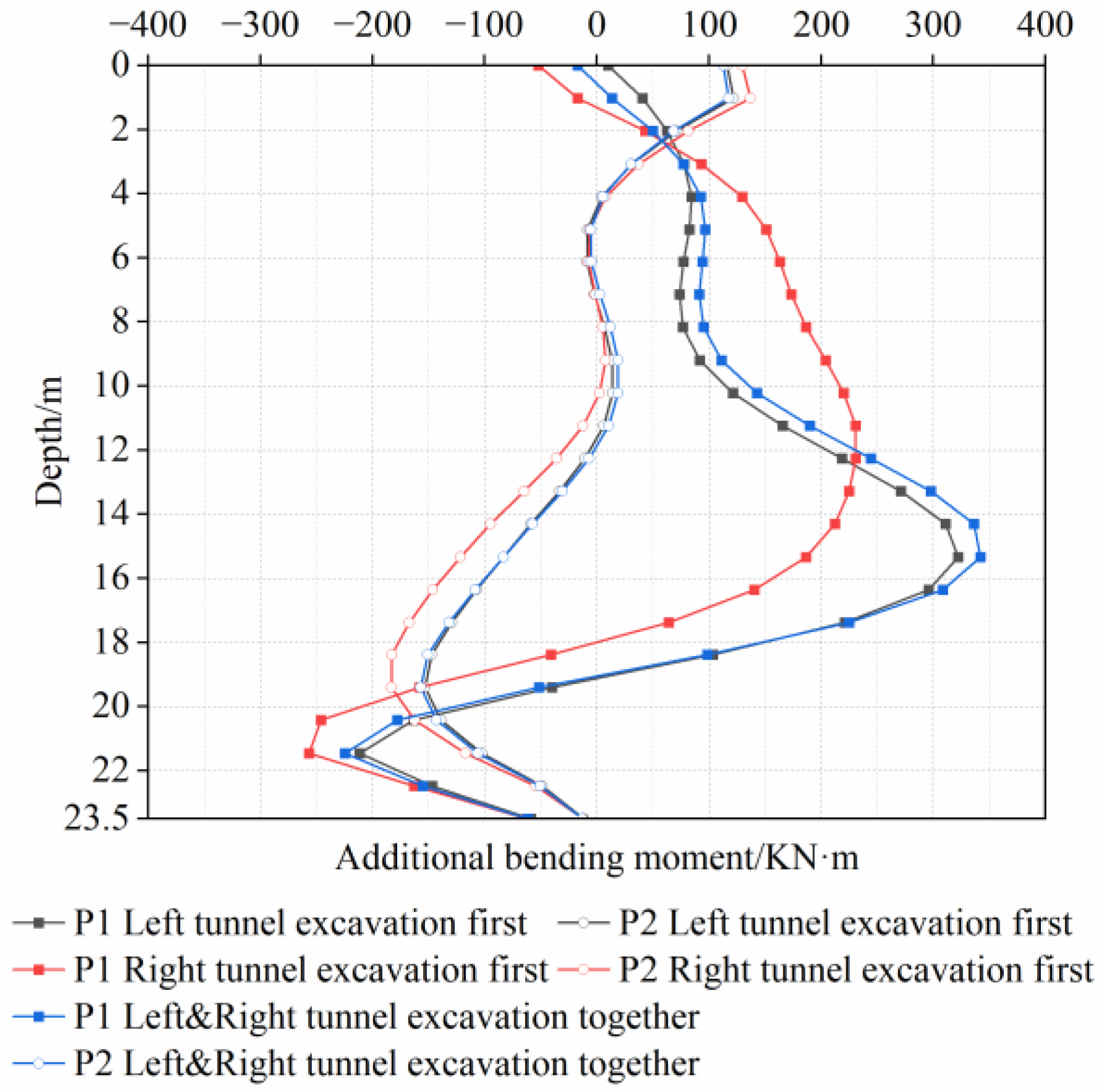
As shown in Figure 25, the additional bending moments of P 1 and P 2 are compared under different construction sequences. Under the conditions of left-tunnel-first and synchronous twin-tunnel excavation, the maximum additional bending moments of P 1 are 322 kN·m and 342 kN·m, respectively, while the corresponding values for P 2 are both 155 kN·m. Under the condition of right-tunnel-first excavation, the maximum additional bending moment on P 1 decreases to 256 kN·m (a reduction of approximately 21% compared with the left tunnel excavation first), whereas that of P 2 increases to 183 kN·m (an increase of approximately 20% relative to the condition of the left-tunnel-first excavation). Based on the above comprehensive analysis of settlement and internal forces, the right-tunnel-first excavation is recommended as the optimal construction sequence, as it achieves a more favorable balance between displacement control and structural integrity relative to other construction sequences.
Figure 25.
Additional bending moments of pile shafts under different construction sequences.
Based on the analysis of the deformation and internal force responses of pile foundations under different construction sequences, the excavation scheme in which the tunnel closer to the piles is constructed first is recommended in engineering practice. This scheme can not only strictly control the pile deformation within a safe range, but also effectively improve the bending bearing capacity of near piles by reducing their additional bending moments, thus fully ensuring the structural safety and stability of both near and far piles.
4.3. Tunnel Face Pressure
To further investigate the influence of tunnel face pressure on pile groups during the excavation of the twin tunnels with small clearance, a comparative analysis of the deformation and mechanical response of twin tunnels and piles was conducted under five tunnel face pressures: 200 kPa, 300 kPa, 400 kPa, 500 kPa, and 600 kPa.
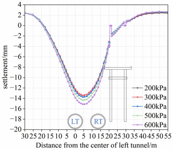
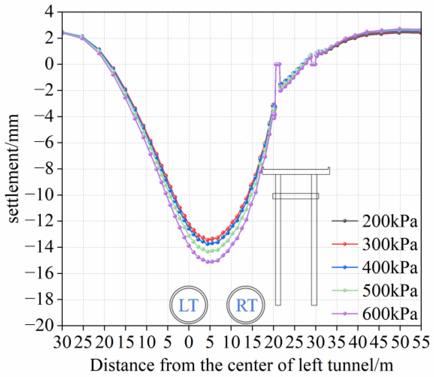
Figure 26 shows the final surface settlement curves under different tunnel face pressures. As the tunnel face pressure gradually increases, the surface settlement also increases accordingly. The maximum surface settlement values are 13.42 mm, 13.43 mm, 13.73 mm, 14.31 mm, and 15.11 mm, respectively. The results indicate that tunnel face pressures of 200 kPa and 300 kPa exert the least influence on the ground surface.
Figure 26.
Surface settlement under different tunnel face pressures.
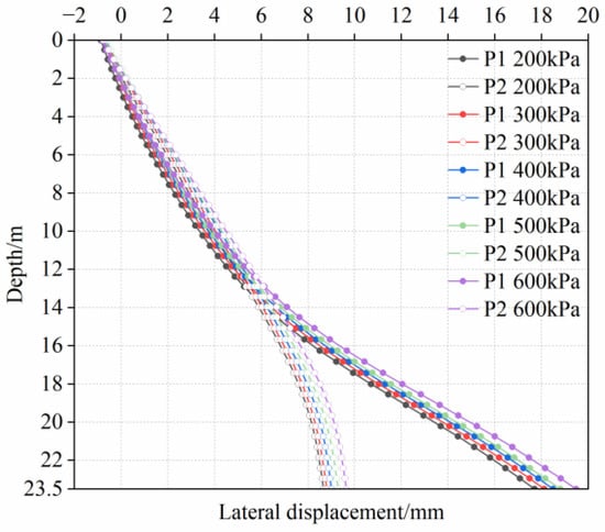
The lateral displacement curves of the pile shafts under different tunnel face pressures are shown in Figure 27. The results indicate that with an increase in tunnel face pressure, the overall lateral displacement of the pile shafts exhibits a slight upward trend, whereas the increase magnitude is not significant.
Figure 27.
Lateral displacements of pile shafts under different tunnel face pressures.
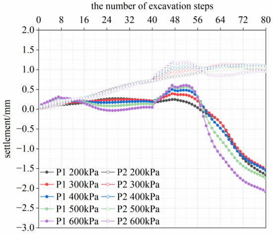
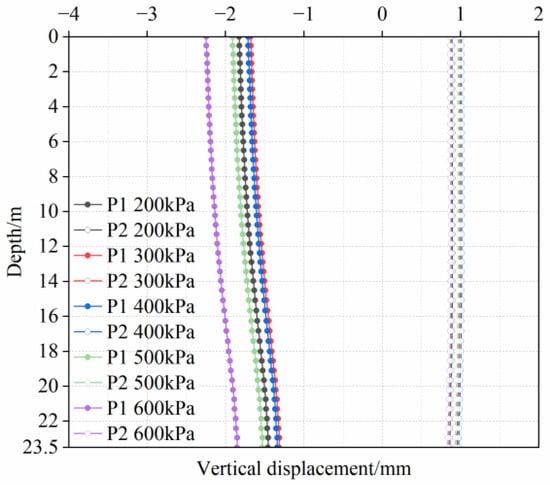
The vertical displacements of pile tops of P 1 and P 2 under different tunnel face pressures are shown in Figure 28. The first 40 steps correspond to the left tunnel excavation, while the subsequent 40 steps correspond to the right tunnel excavation. For P 1, the upward displacements induced during the left tunnel excavation under different tunnel face pressures remain within 1 mm, exerting a minimal difference on its vertical displacement. When the right tunnel excavation commences, all settlement curves exhibit a certain degree of heave. Moreover, the heave value increases with increasing tunnel face pressure. As the shield face approaches the pile group to a distance of 9 m (approximately 5 rings), the excavation significantly disturbs the surrounding soil, resulting in rapid settlement of the pile foundation. The final settlement values are 1.67 mm (200 kPa), 1.52 mm (300 kPa), 1.56 mm (400 kPa), 1.76 mm (500 kPa), and 2.1 mm (600 kPa), respectively.
Figure 28.
Trend of vertical displacements at pile top under different tunnel face pressures.
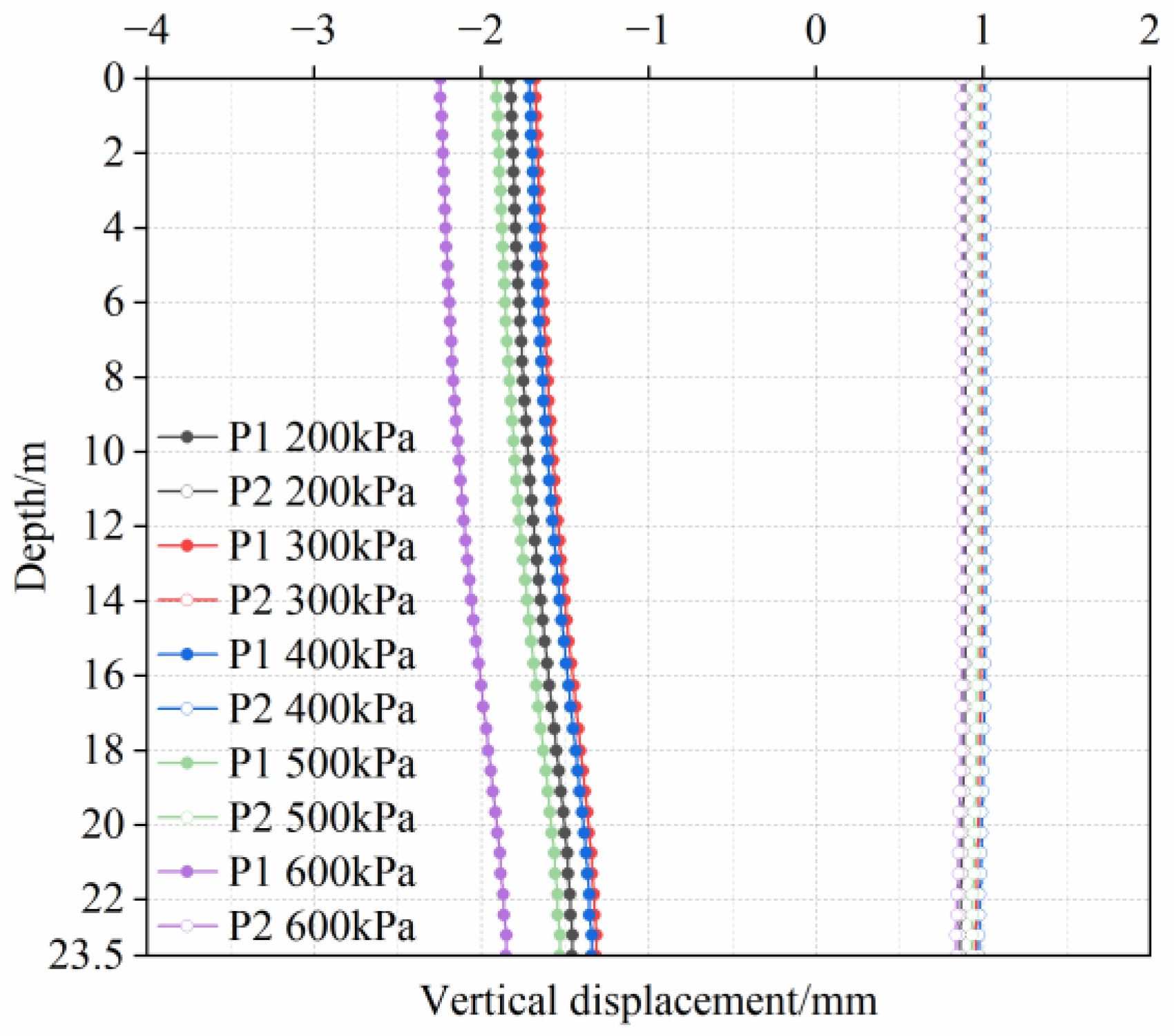
As shown in Figure 29, when the tunnel face pressure is no more than 400 kPa, the vertical displacement of P 1 decreases with increasing tunnel face pressure. Beyond this threshold, the vertical displacement starts to increases. For P 2, there is a slight heave under different tunnel face pressures, with a value of approximately 1 mm.
Figure 29.
Vertical displacement curves of pile shafts under different tunnel face pressures.
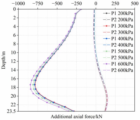
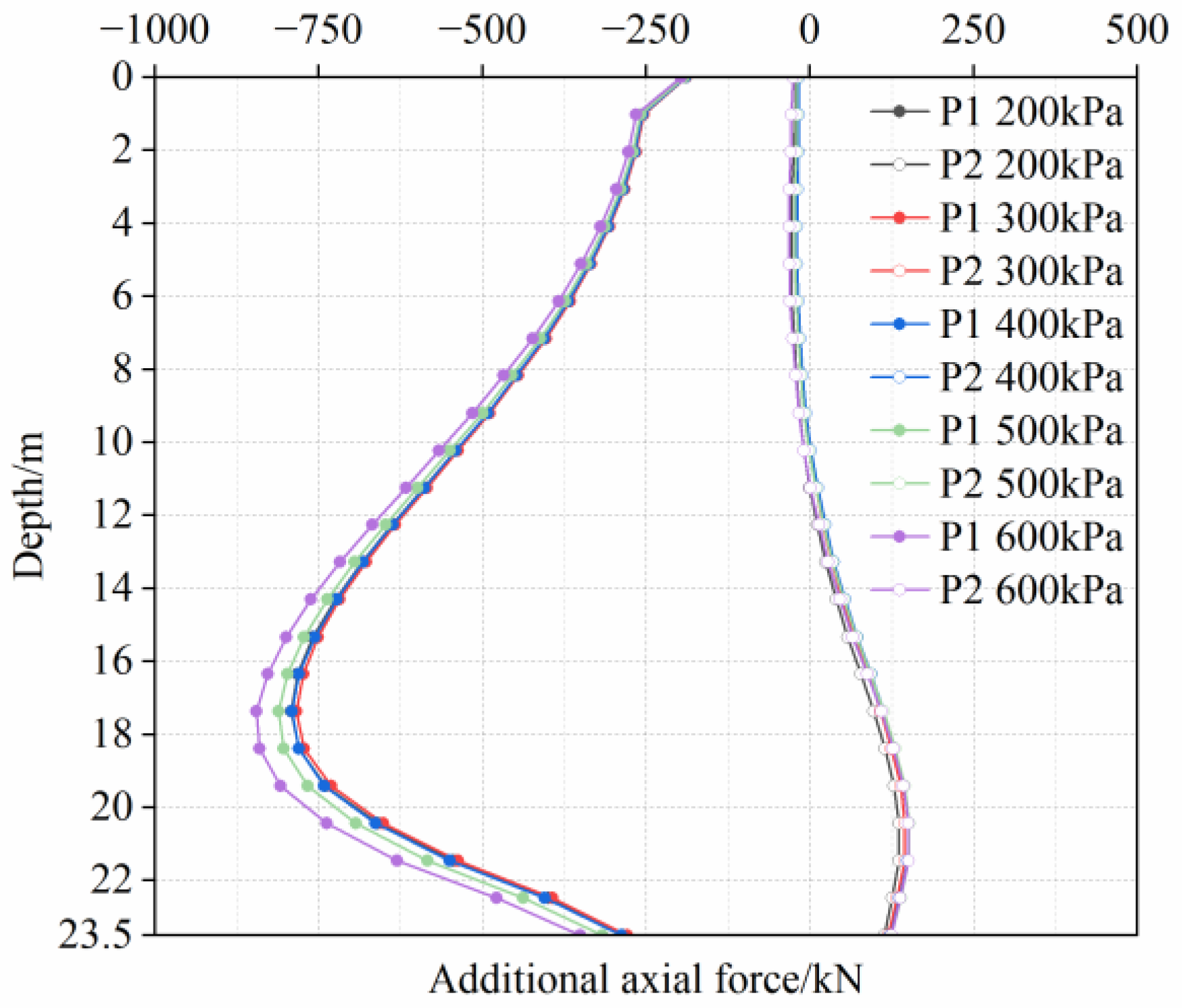
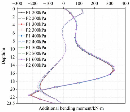
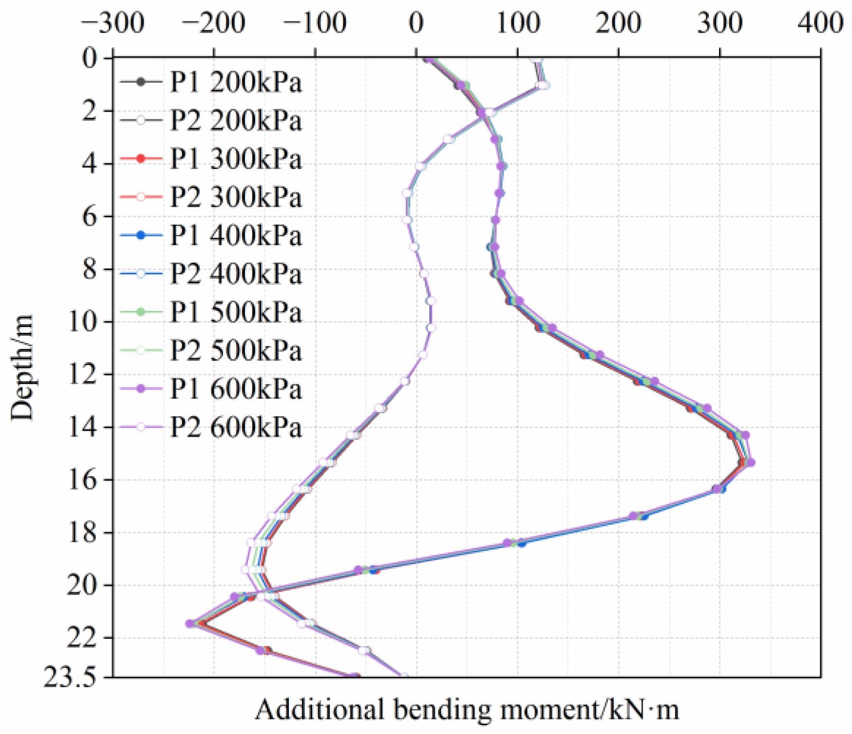
The additional axial forces and bending moments under different face pressures show minimal variation across the range of applied face pressures, as shown in Figure 30 and Figure 31. The maximum variations in additional axial force and bending moment are 53 kN and 16.4 kN·m, respectively.
Figure 30.
Additional axial forces under different tunnel face pressures.
Figure 31.
Additional bending moments under different tunnel face pressures.
Based on the above analysis, tunnel face pressure exerts a significant influence on the vertical displacement of the strata and pile shafts, whereas its effect on the lateral displacement and additional internal forces of pile shafts is relatively limited. When the tunnel face pressure is controlled within the range of 200–300 kPa, it can not only effectively restrain the vertical displacement of the strata and pile foundations but also prevent a substantial increase in their additional internal forces, thereby achieving an optimal balance between the deformation and stress state of pile foundations.
5. Conclusions
This paper employs numerical simulation methods to systematically investigate the soil-tunnel-pile interaction mechanisms during the excavation of the twin tunnels with small clearance adjacent to pile groups under different working conditions, with a specific focus on the sandy-gravel strata in Beijing. The main conclusions are summarized as follows:
- (1)
- During the twin-tunnel excavation, the vertical displacement of the pile decreases with increasing pile length, with the maximum values of 4 mm (13 m), 1.8 mm (23.5 m), and 0.5 mm (33.5 m). The maximum lateral displacements of the pile shafts are located at the tunnel centerline. Compared with the short pile, the maximum lateral displacements of P 1 increase by 12.4 mm (medium pile) and 10.1 mm (long pile). The additional axial forces and bending moments also increase, with maximum axial force values (near the tunnel crown) of 792 kN and 1314 kN, and maximum bending moment values (near the tunnel centerline) of 322 kN·m and 1400 kN·m, respectively. Longer piles exhibit better performance in controlling vertical displacement but suffer more severe lateral deformation and internal force amplification. Therefore, during the construction of large-diameter twin tunnels, particular attention should be paid to the deformation and internal forces of pile foundations near the tunnel centerline, and timely protection measures for piles should be taken.
- (2)
- The tunneling sequence exerts a certain influence on the deformation and internal force of the near pile shaft. The findings indicate that for P 1, excavating the right tunnel first increases the vertical displacement by 1 mm compared with the condition of the left-tunnel excavation first, representing an increase of nearly 50%. Meanwhile, the maximum additional axial force on the pile shaft increases by approximately 300 kN (a 38.8% increase), while the maximum additional bending moment decreases by approximately 100 kN·m (a 21% reduction). For P 2, the additional axial force and bending moment exhibit little difference under different construction sequences. Excavating the right tunnel first effectively reduces the maximum additional bending moment of the near pile, thereby enhancing its bending resistance capacity. Consequently, prioritizing the excavation of the tunnel closer to the pile foundation is recommended for similar engineering applications. This construction scheme can effectively mitigate the bending failure risk of piles and ensure the structural safety and stability of pile foundations during the twin-tunnel construction.
- (3)
- The proper setting of the tunnel face pressure is crucial for controlling the vertical displacement of the pile foundation. Pile foundation deformation is effectively controlled when the tunnel face pressure is maintained between 200 kPa and 300 kPa. Beyond this threshold, control effectiveness is no longer enhanced but rather adversely induces increased ground displacement. In similar engineering applications, the tunnel face pressure should be set within this reasonable range and dynamically adjusted according to field monitoring data, so as to minimize the disturbance induced by tunnel excavation on adjacent pile foundations and ensure their safety and stability during the entire construction process.
However, several limitations remain in this study. The numerical model fails to account for the small-strain stiffness nonlinearity and dilatancy of the soil, as well as the influence of groundwater. Furthermore, no targeted control or reinforcement strategies have been proposed for the disturbed pile foundations and surrounding strata. In future research, a refined numerical model that accounts for fluid-solid coupling, small-strain stiffness nonlinearity, and soil dilatancy will be established to more accurately reveal the complex soil-pile interaction mechanism and to improve the prediction accuracy of pile responses. In addition, targeted reinforcement measures will be further investigated to provide a comprehensive technical reference for deformation prevention and control in similar engineering projects.
Author Contributions
Conceptualization, C.G. and M.S.; methodology, C.G. and L.J.; software, L.J.; validation, M.S.; formal analysis, L.J.; investigation, L.J., H.J. and W.W.; resources, C.G.; data curation, L.J.; writing—original draft preparation, L.J.; writing—review and editing, C.G. and M.S.; supervision, C.G. and M.S.; project administration, H.J. and W.W.; funding acquisition, C.G., H.J. and W.W. All authors have read and agreed to the published version of the manuscript.
Funding
This research was funded by the National Natural Science Foundation of China, grant number 52278385.
Data Availability Statement
The raw data supporting the conclusions of this article will be made available by the authors on request.
Acknowledgments
Special thanks are extended to the Beijing Subway New Airport Extension Line for permitting field monitoring and data collection.
Conflicts of Interest
Authors Houting Jiang and Wenzheng Wang were employed by the company Beijing Municipal Construction Group Co., Ltd. The remaining authors declare that the research was conducted in the absence of any commercial or financial relationships that could be construed as a potential conflict of interest.
References
- Li, Z.; Chen, Z.Q.; Wang, L.; Zeng, Z.K.; Gu, D.M. Numerical Simulation and Analysis of the Pile Underpinning Technology Used in Shield Tunnel Crossings on Bridge Pile Foundations. Underg. Space 2021, 6, 396–408. [Google Scholar] [CrossRef] [Scilit]
- Huang, K.; Sun, Y.W.; Zhou, D.Q.; Li, Y.J.; Jiang, M.; Huang, X.Q. Influence of Water-Rich Tunnel by Shield Tunneling on Existing Bridge Pile Foundation in Layered Soils. J. Cent. South Univ. 2021, 28, 2574–2588. [Google Scholar] [CrossRef] [Scilit]
- Gu, X.; Chen, F.Y.; Zhang, W.G.; Wang, Q.; Liu, H.L. Numerical Investigation of Pile Responses Induced by Adjacent Tunnel Excavation in Spatially Variable Clays. Underg. Space 2022, 7, 911–927. [Google Scholar] [CrossRef] [Scilit]
- Marshall, A.M.; Haji, T. An Analytical Study of Tunnel–Pile Interaction. Tunn. Undergr. Space Technol. 2015, 45, 43–51. [Google Scholar] [CrossRef] [Scilit]
- He, S.Y.; Lai, J.X.; Li, Y.; Wang, K.; Wang, L.X.; Zhang, W.M. Pile Group Response Induced by Adjacent Shield Tunnelling in Clay: Scale Model Test and Numerical Simulation. Tunn. Undergr. Space Technol. 2021, 120, 104039. [Google Scholar] [CrossRef] [Scilit]
- Wang, J.H.; Lei, N.Z.; Tang, X.L.; Wang, Y.L. Research on the Deformation Laws of Adjacent Structures Induced by the Shield Construction Parameters. Buildings 2025, 15, 2426. [Google Scholar] [CrossRef] [Scilit]
- Wu, J.G.; Zhao, J.P.; Tan, Z.S.; Liu, X.Y.; Wang, X.; Liu, M.G. Mechanical Behavior of Large-Diameter Adjacent Shield Tunnelling Bridge Piles: A Case Study of Chunfeng Tunnel. Appl. Sci. 2022, 12, 5418. [Google Scholar] [CrossRef] [Scilit]
- Zhou, J.; Han, K.H.; Chen, W.T. Study on Influence Mechanism of Tunnel Construction on Adjacent Pile Foundation and Resilience Assessment. Buildings 2024, 14, 2818. [Google Scholar] [CrossRef] [Scilit]
- Chen, H.Y.; Liu, J.; Shen, Q.G.; Li, T.J.; Liu, Y. Data-Driven Joint Multiobjective Prediction and Optimization for Tunnel-Induced Adjacent Bridge Pier Displacement: A Case Study in China. Eng. Appl. Artif. Intell. 2025, 142, 109616. [Google Scholar] [CrossRef] [Scilit]
- Soomro, M.A.; Ng, C.W.W.; Liu, K.; Memon, N.A. Pile Responses to Side-by-Side Twin Tunnelling in Stiff Clay: Effects of Different Tunnel Depths Relative to Pile. Comput. Geotech. 2017, 84, 101–116. [Google Scholar] [CrossRef] [Scilit]
- Lim, C.B.; Jusoh, S.N.; Lim, C.X.; Hasbollah, D.Z.A.; Sohaei, H. Tunnel—Pile Interaction Sequence: Parametric Studies. Phys. Chem. Earth 2023, 129, 103312. [Google Scholar] [CrossRef] [Scilit]
- Yang, T.; Liu, S.L.; Zhao, H.; Li, X.R. Study on the Restraint Control of an Isolation Pile on an Existing High-Speed Railway during the Close Passing of a Shield Machine. Front. Earth Sci. 2023, 11, 1142864. [Google Scholar] [CrossRef] [Scilit]
- Simic-Silva, P.T.; Martínez-Bacas, B.; Galindo-Aires, R.; Simic, D. 3D Simulation for Tunnelling Effects on Existing Piles. Comput. Geotech. 2020, 124, 103625. [Google Scholar] [CrossRef] [Scilit]
- Phutthananon, C.; Lertkultanon, S.; Jongpradist, P.; Duangsano, O.; Likitlersuang, S.; Jamsawang, P. Numerical Investigation on the Responses of Existing Single Piles due to Adjacent Twin Tunneling Considering the Lagging Distance. Underg. Space 2023, 11, 171–188. [Google Scholar] [CrossRef] [Scilit]
- Lim, C.X.; Jusoh, S.N.; Lim, C.B.; Abdullah, R.A.; Mohd Yunus, N.Z. Tunnel Depth Effect to Pile in Tunnel’s Influence Zone. Phys. Chem. Earth 2023, 129, 103298. [Google Scholar] [CrossRef] [Scilit]
- Zhang, Z.G.; Zhang, C.P.; Jiang, K.M.; Wang, Z.W.; Jiang, Y.J.; Zhao, Q.H.; Lu, M.H. Analytical Prediction for Tunnel-Soil-Pile Interaction Mechanics Based on Kerr Foundation Model. KSCE J. Civ. Eng. 2019, 23, 2756–2771. [Google Scholar] [CrossRef] [Scilit]
- Huang, K.; Sun, Y.W.; Yang, J.S.; Li, Y.J.; Jiang, M.; Huang, X.Q. Three-Dimensional Displacement Characteristics of Adjacent Pile Induced by Shield Tunneling under Influence of Multiple Factors. J. Cent. South Univ. 2022, 29, 1597–1615. [Google Scholar] [CrossRef] [Scilit]
- Cao, K.; Chen, M.H.; Zhang, M.H.; Ding, W.T.; Shang, C.H.; Ruan, H.; Huang, X.H. Calculation Method for the Response Changes of Existing Bridge Piles Caused by Side Penetration of Shield Tunnels Considering Construction Factors and Cumulative Impact of Excavation. Comput. Geotech. 2024, 172, 106472. [Google Scholar] [CrossRef] [Scilit]
- Wu, T.H.; Gao, Y.T.; Huang, C.F.; Jin, A.B.; Zhou, Y.; Li, J.W. Horizontal Mechanical Responses of Single Pile Induced by Adjacent Tunneling Considering the Effect of Multiple Factors Based on Timoshenko Beam-Kerr Foundation Model. Appl. Math. Model. 2025, 140, 115885. [Google Scholar] [CrossRef] [Scilit]
- Chen, X.L.; Zhang, X.M.; Zhou, X.S.; Ou, X.F.; Liu, J.Q.; Liu, H.P.; Yu, W. Vertical Mechanical Response of Axial Loaded Pile to Tunneling-Induced Pile Exposure. Comput. Geotech. 2023, 159, 105416. [Google Scholar] [CrossRef] [Scilit]
- Liu, W.; Wang, M.; Luo, G.; Lu, W.; Xiao, H. Horizontal Response of Existing Pile Induced by Adjacent Shield Tunnelling with Large Longitudinal Slope. Tunn. Undergr. Space Technol. 2024, 153, 106036. [Google Scholar] [CrossRef] [Scilit]
- Guo, C.X.; Yue, H.Y.; Tao, Y.Y.; Liu, G.; Kong, F.C.; Lu, D.C.; Du, X.L. Mechanical Response of Pile Group and Stratum Induced by Shallow Tunneling Based on the Model Test. Tunn. Undergr. Space Technol. 2025, 159, 106480. [Google Scholar] [CrossRef] [Scilit]
- Lin, Q.T.; Lu, D.C.; Lei, C.M.; Tian, Y.; Gong, Q.M.; Du, X.L. Model Test Study on the Stability of Cobble Strata during Shield Under-Crossing. Tunn. Undergr. Space Technol. 2021, 110, 103807. [Google Scholar] [CrossRef] [Scilit]
- Franza, A.; Marshall, A.M. Centrifuge Modeling Study of the Response of Piled Structures to Tunneling. J. Geotech. Geoenviron. Eng. 2018, 144, 04017110. [Google Scholar] [CrossRef] [Scilit]
- Song, G.Y.; Marshall, A.M. Centrifuge Study on the Influence of Tunnel Excavation on Piles in Sand. J. Geotech. Geoenviron. Eng. 2020, 146, 04020130. [Google Scholar] [CrossRef] [Scilit]
- Yoo, C.; Abbas, Q. Interaction between Two-Arch Tunnel and Pile Supported Bridge—An Experimental Investigation. Tunn. Undergr. Space Technol. 2021, 112, 103869. [Google Scholar] [CrossRef] [Scilit]
- Jiang, T.; Wang, L.J.; Zhang, J.R.; Jia, H.; Pan, J.S. Effect of Water Content on Near-Pile Silt Deformation during Pile Driving Using PIV Technology. Geomech. Eng. 2020, 23, 139–149. [Google Scholar] [CrossRef]
- Huang, F.; Wang, Y.T.; Zhang, M.; Jiang, W.T.; Ji, H.B.; Pan, Q.J. Model Test Study of Punching Shear Failure Mode of the Bearing Stratum Induced by Tunneling Beneath an Existing Pile. Tunn. Undergr. Space Technol. 2025, 158, 106459. [Google Scholar] [CrossRef] [Scilit]
- Gokuldas, S.; Banerjee, S.; Nimbalkar, S.S. Effects of Tunneling-Induced Ground Movements on Stability of Piled Raft Foundation: Three-Dimensional Finite-Element Approach. Int. J. Geomech. 2020, 20, 04020104. [Google Scholar] [CrossRef] [Scilit]
- Ayasrah, M.; Qiu, H.S.; Zhang, X.D. Influence of Cairo Metro Tunnel Excavation on Pile Deep Foundation of the Adjacent Underground Structures: Numerical Study. Symmetry 2021, 13, 426. [Google Scholar] [CrossRef] [Scilit]
- Soomro, M.A. 3D Finite Element Analysis of Effects of Twin Stacked Tunnels at Different Depths and with Different Construction Sequence on a Piled Raft. Tunn. Undergr. Space Technol. 2021, 109, 103759. [Google Scholar] [CrossRef] [Scilit]
- Soomro, M.A.; Mangi, N.; Cui, Z.D.; Liu, K.; Mangnejo, D.A. Evaluation of Response Mechanisms in an Elevated Pile Group Subjected to Lateral Loading Caused by Twin-Tunnelling. Comput. Geotech. 2024, 171, 106334. [Google Scholar] [CrossRef] [Scilit]
- Chen, Y.R.; Yang, B. A Parametric Study to Assess the Effects of Twin-Tunnel Excavation on Bridge Pile Groups. Indian Geotech. J. 2025, 1–17. [Google Scholar] [CrossRef] [Scilit]
- Zhang, S.; Zhang, X.; Ning, X.; Lu, H.Y.; Jiang, M.M.; Wei, S.G.; Xiao, X.L. Effect of Shield-Tunnel Construction on the Horizontal Response of Adjacent Piles in a Silty Layer. Buildings 2023, 13, 2455. [Google Scholar] [CrossRef] [Scilit]
- Kanagaraju, R.; Krishnamurthy, P.; Dodagoudar, G.R.; Velusamy, S. Numerical Analysis of Displacements in Concrete Pile Foundations Induced by Adjacent Tunnel Excavation in Sandy Soils. Matéria 2024, 29, e20240391. [Google Scholar] [CrossRef] [Scilit]
- He, D.L.; Cheng, Y.H.; Liu, H.W.; Lin, H. Pile–Soil Interaction and Group Pile Effect in Composite Foundation under Different Pile Length Conditions. Buildings 2025, 15, 1248. [Google Scholar] [CrossRef] [Scilit]
- Jiao, N.; Ding, J.W.; Liao, Z.S.; Wan, X.; Gao, P.J. Impact of Double Shield Tunnel Construction on Adjacent Pile Foundation in Silty Fine Sand Strata. J. Perform. Constr. Facil. 2025, 39, 04025061. [Google Scholar] [CrossRef] [Scilit]
- Wu, T.H.; Gao, Y.T.; Huang, C.F.; Zhou, Y.; Li, J.W.; Qi, W.R. Impact of Side-by-Side Twin Tunneling with Various Tunnel-Pile Clearances on Pile Group Responses under a Fluid-Solid Coupling Effect. Alex. Eng. J. 2025, 127, 1–17. [Google Scholar] [CrossRef] [Scilit]
- Su, J.; Pan, Y.Q.; Niu, X.K.; Zhang, C.P. Effect of Shield Tunneling on Adjacent Pile Foundations in Water-Rich Strata. Transp. Geotech. 2025, 52, 101557. [Google Scholar] [CrossRef] [Scilit]
- Huang, K.; Sun, Y.W.; He, J.; Huang, X.Q.; Jiang, M.; Li, Y.J. Comparative Study on Grouting Protection Schemes for Shield Tunneling to Adjacent Viaduct Piles. Adv. Mater. Sci. Eng. 2021, 2021, 5546970. [Google Scholar] [CrossRef] [Scilit]
- Qiu, H.S.; Wang, Z.; Ayasrah, M.; Fu, C.B.; Luo, G. Numerical Study on the Reinforcement Measures of Tunneling on Adjacent Piles. Symmetry 2022, 14, 288. [Google Scholar] [CrossRef] [Scilit]
- Tang, J.S.; Bi, Y.Q.; Zhang, B. Grouting Reinforcement Measures for a Shield Tunnel Undercrossing Foundation of a Pile Group. Int. J. Geomech. 2024, 24, 04024273. [Google Scholar] [CrossRef] [Scilit]
- Fatahi, B.; Nguyen, Q.V.; Xu, R.; Sun, W.-J. Three-Dimensional Response of Neighboring Buildings Sitting on Pile Foundations to Seismic Pounding. Int. J. Geomech. 2018, 18, 04018007. [Google Scholar] [CrossRef] [Scilit]
- Bagheri, M.; Ranjbar Malidarreh, N.; Ghaseminejad, V.; Asgari, A. Seismic Resilience Assessment of RC Superstructures on Long–Short Combined Piled Raft Foundations: 3D SSI Modeling with Pounding Effects. Structures 2025, 81, 110176. [Google Scholar] [CrossRef] [Scilit]
- Zhang, Z.H.; Wang, A.B.; Deng, G.Q.; Hu, J.S. Analysis of the Influence of Tunnel Span on the Stability of Unlined Circular Tunnels Subjected to Intense Dynamic Load. Buildings 2026, 16, 1180. [Google Scholar] [CrossRef] [Scilit]
- Shayanfar, J.; Barros, J.A.O.; Rezazadeh, M.; Jafarian Kafshgarkolaei, H. Enhancing the Performance of Heat-Damaged Rectangular RC Columns Using Prestressed FRP Confinement. Constr. Build. Mater. 2025, 501, 144346. [Google Scholar] [CrossRef] [Scilit]
- He, C.; Wei, J.; Liang, H.; Chen, Z.Z.; Ding, W.Q.; Li, B. Structural Behavior Analysis for Existing Pile Foundations Considering the Effects of Shield Tunnel Construction. Buildings 2025, 15, 3263. [Google Scholar] [CrossRef] [Scilit]
- Ng, C.W.W.; Lu, H. Effects of the Construction Sequence of Twin Tunnels at Different Depths on an Existing Pile. Can. Geotech. J. 2014, 51, 173–183. [Google Scholar] [CrossRef] [Scilit]
- Soomro, M.A.; Kumar, M.; Xiong, H.; Mangnejo, D.A.; Mangi, N. Investigation of Effects of Different Construction Sequences on Settlement and Load Transfer Mechanism of Single Pile Due to Twin Stacked Tunnelling. Tunn. Undergr. Space Technol. 2020, 96, 103171. [Google Scholar] [CrossRef] [Scilit]
- Soomro, M.A.; Samo, S.R.; Saand, A.; Mangi, N.; Mangnejo, D.A. Numerical Parametric Study of Settlement and Load Transfer Mechanism of Pile Group Due to Twin Stacked Tunnelling with Different Construction Sequences. Eur. J. Environ. Civ. Eng. 2019, 26, 1064–1096. [Google Scholar] [CrossRef] [Scilit]
- Huang, K.; Sun, Y.W.; Huang, X.Q.; Li, Y.J.; Jiang, M.; Liu, R.N. Effects of Different Construction Sequences on Ground Surface Settlement and Displacement of Single Long Pile due to Twin Paralleled Shield Tunneling. Adv. Civ. Eng. 2021, 2021, 5559233. [Google Scholar] [CrossRef] [Scilit]

Disclaimer/Publisher’s Note: The statements, opinions and data contained in all publications are solely those of the individual author(s) and contributor(s) and not of MDPI and/or the editor(s). MDPI and/or the editor(s) disclaim responsibility for any injury to people or property resulting from any ideas, methods, instructions or products referred to in the content. |
© 2026 by the authors. Licensee MDPI, Basel, Switzerland. This article is an open access article distributed under the terms and conditions of the Creative Commons Attribution (CC BY) license.