


Abstract
Assembled H-shaped steel strut (AHSS) has been widely applied in deep excavation projects. In this study, the collapse failure of AHSS C1 in a deep excavation project in China was investigated. The collapse of C1 was directly attributed to the settlement of its supporting columns in the mid-span, which was triggered by a nearby pit bottom leakage through an exploration borehole. Then the implementation of the emergency measures and reconstruction works were introduced. Theoretical and numerical pre-assessments confirmed that the reconstructed C1 exhibited adequate safety for strength, in-plane stability and out-of-plane stability, with all steel components and bolts within their safe limits. The good working performance of reconstructed C1 was finally verified through the monitoring results (i.e., strut axial force, soil horizontal displacement, column vertical displacement, road settlement and building settlement) of the foundation pit during the subsequent soil excavation and basement construction. This study is believed to provide references for future excavation projects using AHSS with similar risks.
1. Introduction
With the rapid urbanization and increasing demand for underground space, deep excavation projects have become more prevalent, marked by greater excavation depth, larger scale and more complex surrounding environment [1]. These projects encounter significant safety control challenges. However, failures of retaining and supporting structures in deep excavation projects were still frequently reported worldwide, resulting in substantial economic losses [2,3,4,5,6,7,8,9]. The mechanisms underlying these failures, the corresponding precautionary measures and the reconstruction plans require thorough studies.
In deep excavation projects, struts act as an internal supporting system for the safety control of whole foundation pit, and the failure of strut can be attributed to different factors. One common failure mode of strut is crush or fracture due to extreme external force or internal force. It can be considered as the problem of strength. For example, Zhang [10] reported the local damage of concrete strut caused by the collision from an overturned excavator. Timely backfill of soil was carried out at the damage point. The damaged strut was reinforced by steel angles combined with batten plates, and steel plates were added at the beam joints of the strut. In a study by Zhou et al. [11], severe breakage of concrete struts caused by the complex internal forces took place. It was triggered by the improper spatial layout of strut and the overestimation of passive zone reinforcement. During the reconstruction, apart from the backfill of soil and the addition of new retaining piles in the collapsed region, the supporting slabs were set instead of the collapsed strut and other strut experiencing complex internal forces. Huang et al. [12] studied the collapse of concrete strut at the convex corner of a foundation pit. The accident was mainly attributed to the unbalanced force acting at the convex corner, which was triggered by the inappropriate spatial layout of the strut, the overestimation of soil strength and the poor construction quality of the retaining and supporting structures. Bidirectional reinforcement was carried out in the reconstruction of convex corner, including adding cross strut at one side and inclined struts at the other side.
Another failure mode of struts involves unacceptable deformation or instability due to abnormal displacement or lack of constraint at its joints connecting the retaining pile and the supporting column. It can be considered as the problem of stiffness. Xue et al. [13] reported the instability of steel pipe strut in a foundation pit. It was mainly caused by the lack of efficient connections of two joints, including one between the strut and wale, and the other between the wale and retaining pile. The two weak points finally caused the fall of strut with the overturned wale. In a study by Tan et al. [5], the temporary three-step earthen slope experienced post-excavation sliding failure. Slide debris traveling on sloped terrain led to detachment of steel pipe struts against diaphragm walls, snapping of supporting columns, and breakage of concrete struts. Zhou and Du [14] also investigated the instability of steel pipe strut in a deep excavation project. It was mainly triggered by the underestimated axial force, as an unexplored grike resulted in much larger axial force. The relatively weak hoop for fixing the strut and its supporting beam aggravated the failure. During the reconstruction of failed steel pipe struts, the backfill of soil or concrete and the installation of new steel pipe struts with strengthened joints were generally adopted. In the study of Zhu [15], a concrete strut showed great horizontal displacement in the middle region. This was primarily caused by the horizontal displacement of the underlying supporting columns, triggered by an extremely large difference in excavation depths on either side. Backfill of soil at the two ends of the strut, addition of slab in the whole strut, addition of inclined steel pipe against the middle region of the strut, and control of symmetrical excavation were carried out for the reconstruction.
Assembled H-shaped steel strut (AHSS) has been widely used in deep excavation projects [16,17,18,19,20]. Early studies on AHSS focused on theoretical analysis of its stability. For example, after setting a vertical displacement for the supporting beam, which is simplified as an elastic spring, Liu et al. [21] found that the ultimate bearing capacity of AHSS was controlled by the stiffness of the supporting beam. The effective length of AHSS for out-of-plane stability analysis can be set as the horizontal spacing of the supporting beam, only if the stiffness of the supporting beam reaches a critical value. Li et al. [22] studied the in-plane stability of AHSS with supporting beams by energy method, and the solution between the critical axial load of AHSS and the stiffness of the supporting beam was obtained. However, the studies on the failure of AHSS in real projects are quite limited. Recently, Xu et al. [23] reported abnormal in-plane flexural deformation of one AHSS in a deep excavation project. The difference in horizontal movement of the wale at the two sides of each end of AHSS was found to be the leading factor causing the abnormal flexural deformation. Four pairs of U-bars were used to ensure the in-plane stability of the AHSS, by connecting it with adjacent strut.
In this study, the collapse failure of AHSS in a foundation pit is introduced. Causes of the accident are identified through in situ investigation and theoretical analysis. The implementation of emergency measures and reconstruction works are discussed. The safety redundancy of the reconstructed AHSS is pre-assessed through theoretical and numerical analysis. The effectiveness of the reconstruction works was verified through analysis of monitoring results of the foundation pit. This study is believed to provide a wealth of experience and guidance for the safety control of AHSS in future excavation projects.
2. Description of the Excavation Project
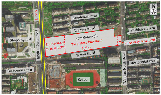
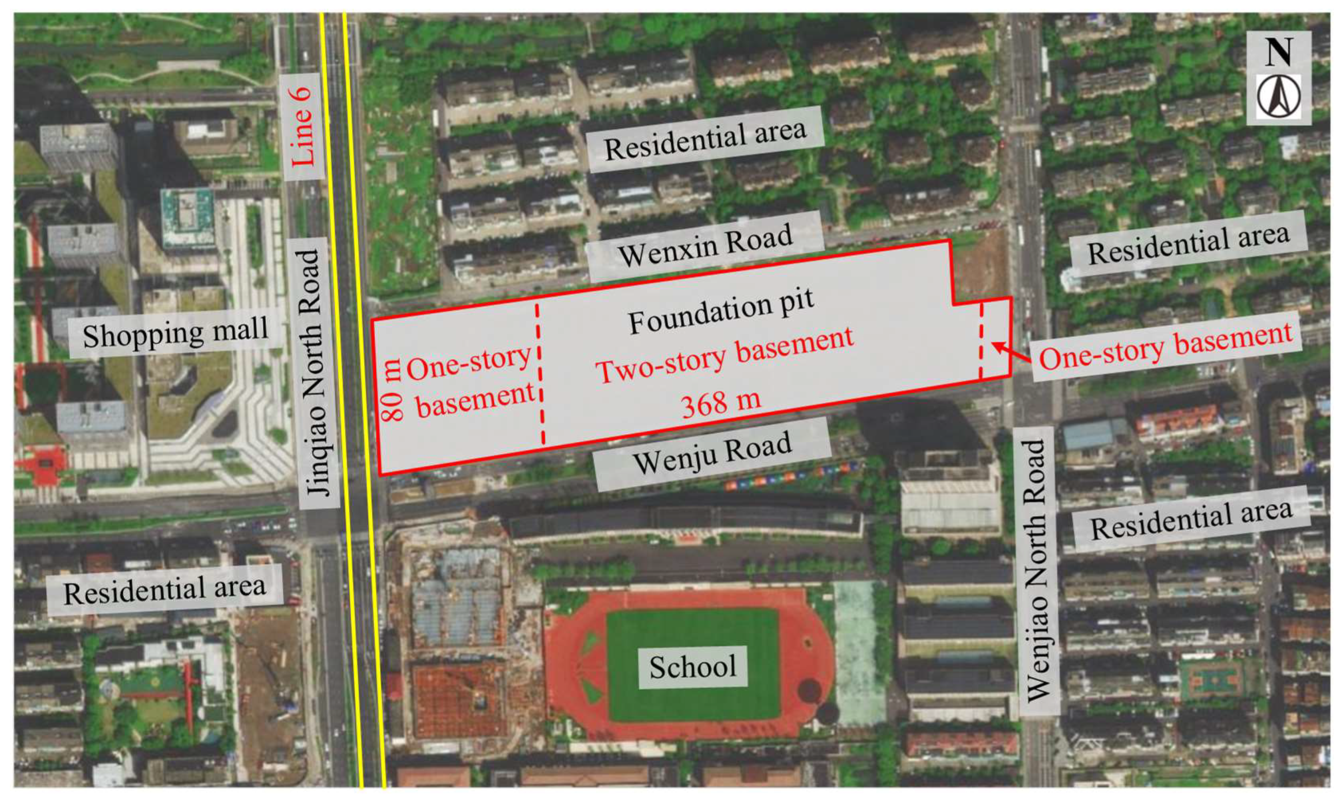
The excavation project is situated in the silt region of Hangzhou, China. It is for the construction of four office buildings and one hotel and covers a total area of 34,266 m2. The ground surface elevation of the site is 6.18–7.96 m (1985 National Elevation Datum). The location and surrounding environment of the foundation pit is shown in Figure 1. The foundation pit is in a rectangular shape, with a length (east–west direction) of about 368 m and a width (north–south direction) of about 80 m and has a convex corner at the northeast region. Roads and residential districts lie to the east and north of the project. A road and a school are located to the south. A road and a shopping mall are to the west, with a subway line running beneath the road. The subway line is approximately 27 m away from the edge of the foundation pit.
Figure 1.
Location and surrounding environment of the project.
According to BHURDZ [24], the region of the foundation pit within the 50 m subway protection line should be specially designed. One-storey basement with an excavation depth of about 6.85 m is designed for the west region of the foundation pit within 100 m away from the subway line. In addition, one-storey basement with an excavation depth of about 6.5 m is designed for the east region to protect adjacent important pipelines. Two-storey basement with an excavation depth of about 10.35 m is designed for the remaining region.
2.1. Geological Conditions
The construction site is flat. From top to bottom, there is miscellaneous fill (layer 1), silty clay with clayey silt (layer 2), muddy silty clay (layer 3), silty sand (layer 4), rounded gravel (layer 6), and completely decomposed granite (layer 10-1). The physical and mechanical properties of the strata are shown in Table 1.
Table 1.
Physical and mechanical properties of soils.
The groundwater at the construction site consists of phreatic and confined water. The phreatic water is primarily found in upper soil layers, with a depth of 0.30–1.80 m and an annual fluctuation of 1.00–2.00 m. The confined water is primarily found in silty sand (Layer 4) and rounded gravel (Layer 6), which have great permeability. The top of the confined water lies at a depth of 16.7–20.8 m, with an aquifer thickness of 7.5–11.8 m. The confined water head has a depth of about 4.0 m. No adverse geological conditions or unfavorable buried objects were observed at the site.
2.2. Design of the Foundation Pit
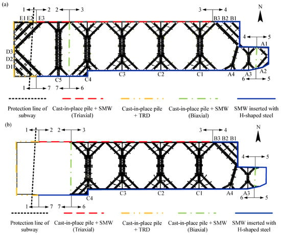
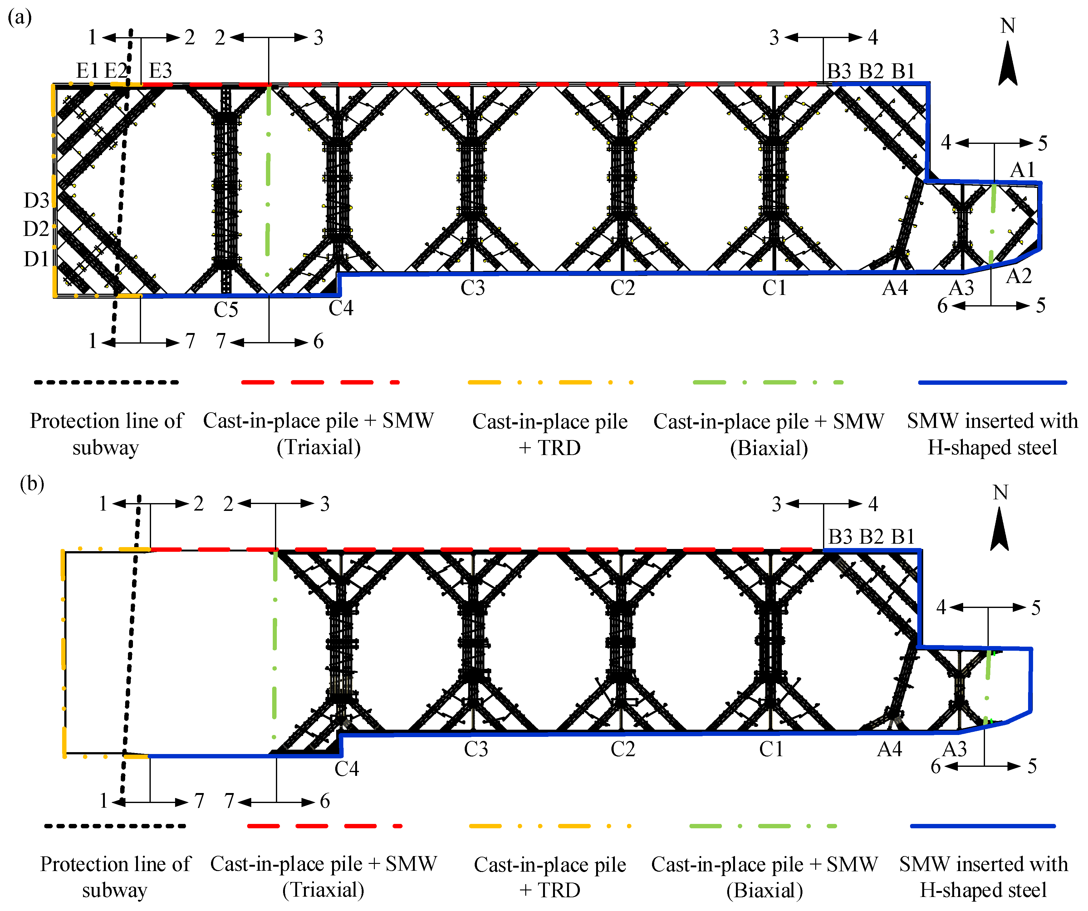
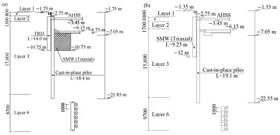
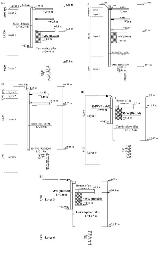
The designed safety level of the foundation pit is Class One according to BHURDZ [25]. The designed foundation pit is shown in Figure 2 and Figure 3.
Figure 2.
Plan view of the foundation pit: (a) the 1st level of AHSS; (b) the 2nd level of AHSS.
Figure 3.
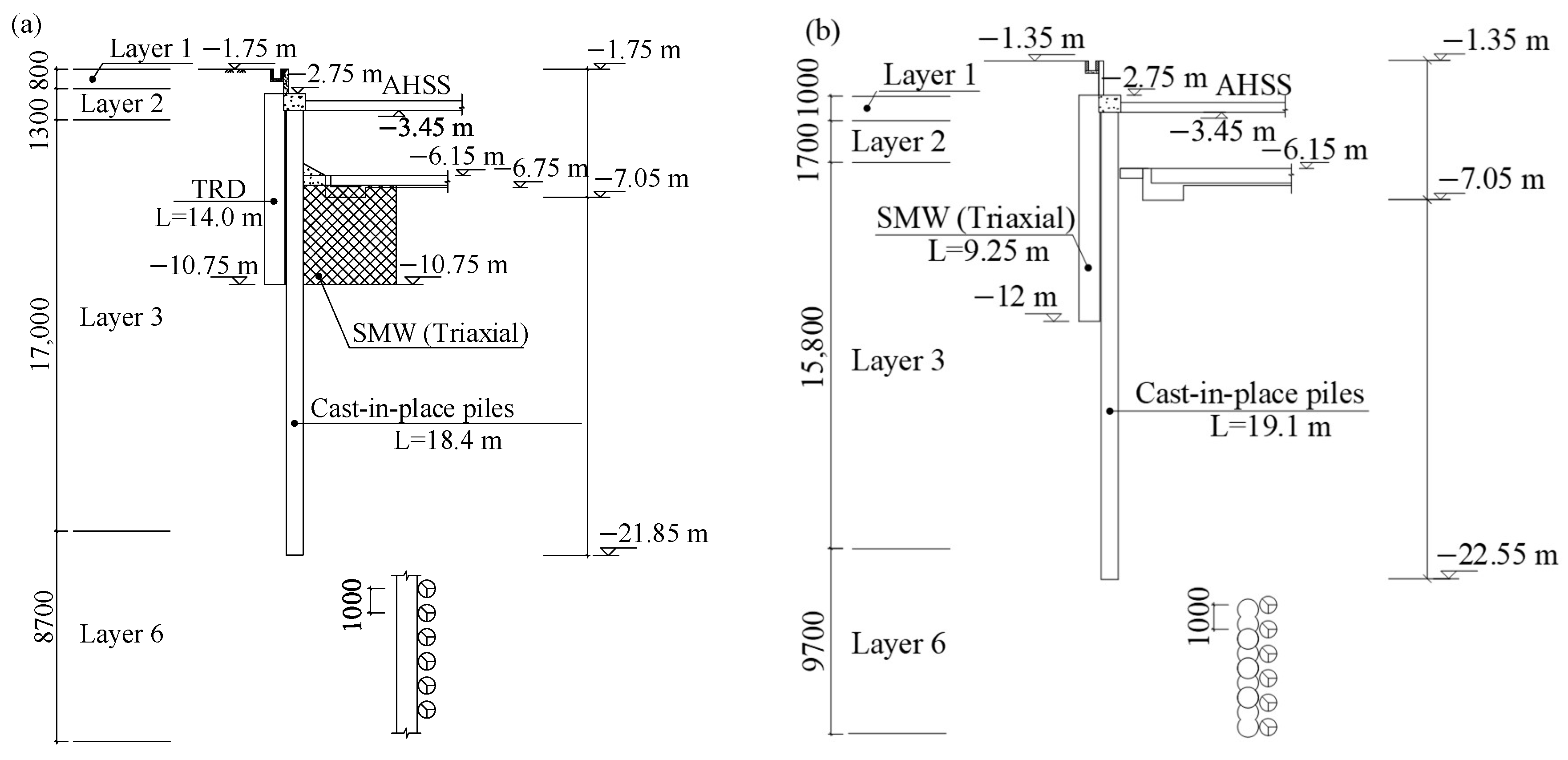
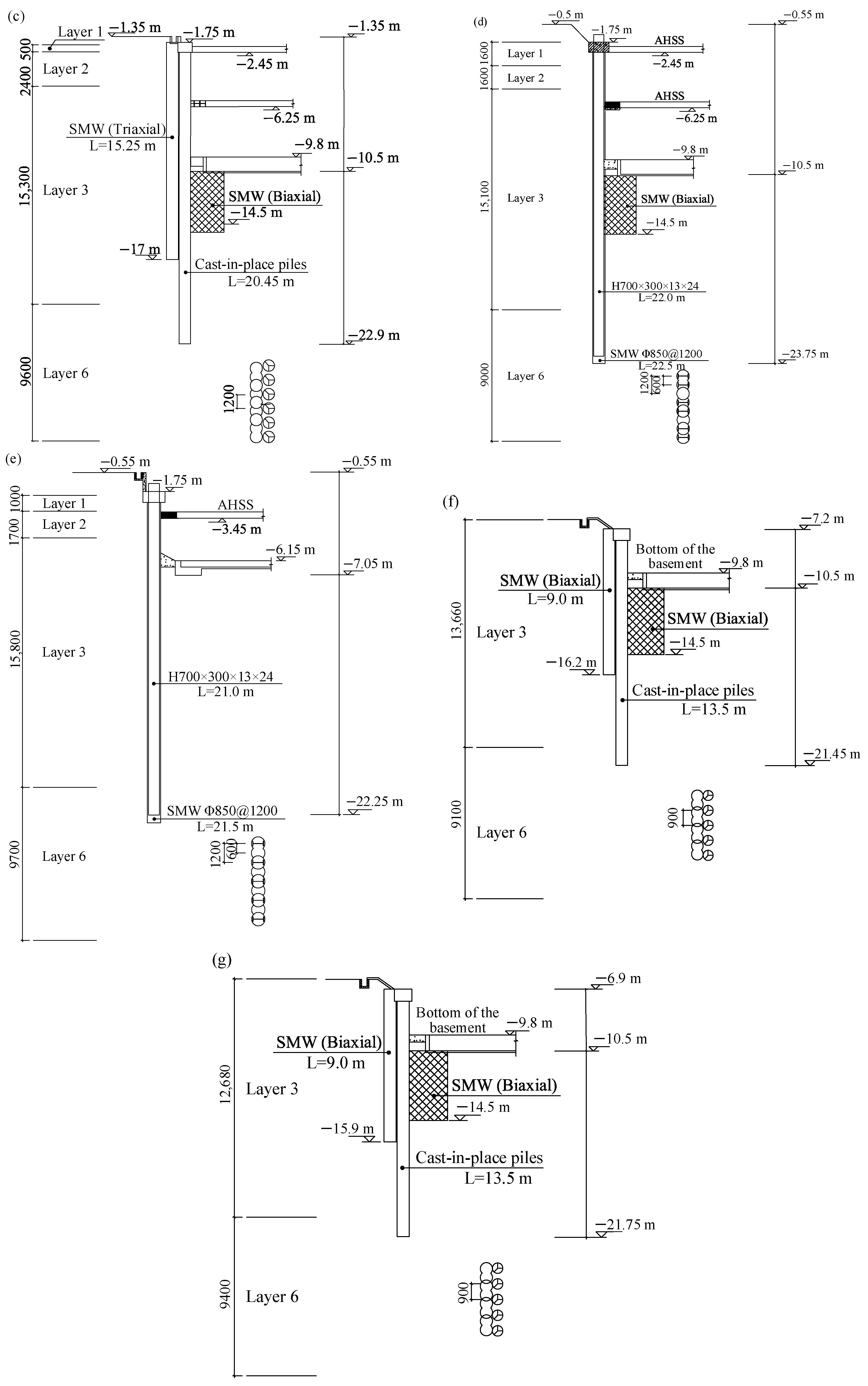
Cross-section view of the foundation pit: (a) section 1-1; (b) section 2-2; (c) section 3-3; (d) section 4-4 and 6-6; (e) section 5-5 and 7-7; (f) section of the west partition wall; (g) section of the east partition wall (Unit: mm).
For the one-storey basement in the west region, one level of AHSS is applied (see Figure 2). For the area within the 50 m subway protection line (see Figure 3a), cast-in-place piles (diameter of 700 mm, spacing of 1000 mm, length of 18.4 m) with trench-cutting remixing deep-wall (TRD) (thickness of 850 mm, length of 14 m) are used. Three corner struts are set at the northwest corner (E1–E3) and southwest corner (D1–D3), respectively. Soil mixing wall (SMW) is set for the passive zone reinforcement (width of 3.85 m, thickness of 4 m). For the north area (see Figure 3b), cast-in-place piles (diameter of 700 mm, spacing of 1000 mm, pile length of 19.1 m) with SMW (diameter of 850 mm, spacing of 600 mm, length of 9.25 m) are used. For the south area (see Figure 3e), SMW (diameter of 850 mm, spacing of 1200 mm, length of 21.5 m) inserted with H-shaped steel (HS) (H700 × 300 × 13 × 24, length of 21 m) are used. One cross strut (C5) is set against the north and south sides.
For the two-storey basement in the middle region (see Figure 2), two levels of AHSS are applied, and SMW is set for the passive zone reinforcement (width of 2.2 m, thickness of 4 m). For the north area (see Figure 3c), cast-in-place piles (diameter of 800 mm, spacing of 1000 mm, length of 20.45 m) with SMW (diameter of 850 mm, spacing of 600 mm, length of 15.25 m) are used. For the south area (see Figure 3d), SMW (diameter of 850 mm, spacing of 1200 mm, length of 22.5 m) inserted with HS (H700 × 300 × 13 × 24, length of 22 m) are used. Four cross struts (C1–C4) are set against the north and south sides at each level. For the northeast corner (see Figure 3d), SMW (diameter of 850 mm, spacing of 1200 mm, length of 22.5 m) inserted with HS (H700 × 300 × 13 × 24, length of 22 m) are used, and three corner struts (B1–B3) are set at each level. For the convex corner, two cross struts (A3–A4) are set at each level.
For the one-storey basement in the east region (see Figure 2), one level of AHSS and SMW (diameter of 850 mm, spacing of 1200 mm, length of 21.5 m) inserted with HS (H700 × 300 × 13 × 24, length of 21 m) are used. One corner strut is set at the northeast corner (A1) and southeast corner (A2), respectively.
The partition wall is set between the one-storey and two-storey basements (see Figure 2). For the western partition wall (see Figure 3f), cast-in-place piles (diameter of 600 mm, spacing of 900 mm, length of 13.5 m) with SMW (diameter of 700 mm, spacing of 1000 mm, length of 9 m) are used. For the eastern partition wall (see Figure 3g), cast-in-place piles (diameter of 700 mm, spacing of 1000 mm, length of 13.5 m) with SMW (diameter of 700 mm, spacing of 1000 mm, length of 9 m) are used. SMW is set for the passive zone reinforcement inside the two-storey basement (width of 2.2 m, thickness of 4 m).
The concrete for cast-in-place piles is C30. For TRD and SMW, P.O 42.5 cement is used, and the cement content and water–cement ratio are 20–25% and 1.0–2.0, respectively. Each AHSS is assembled by several rows of HS (H350 × 350 × 12 × 19, Q355B), cover plate (20 × 2350 × 750, Q355B) and cover bar (C32b, Q235B). It rests on supporting beams (H350 × 350 × 12 × 19, Q235B), which are connected to steel columns (H300 × 300 × 10 × 15, Q235B, embedment depth of 10 m) via steel brackets. All the above steel components are connected through high-strength bolts (20MnTiB, Grade 10.9). The preloads for each AHSS are shown in Table 2.
Table 2.
Preload of the strut.
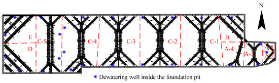
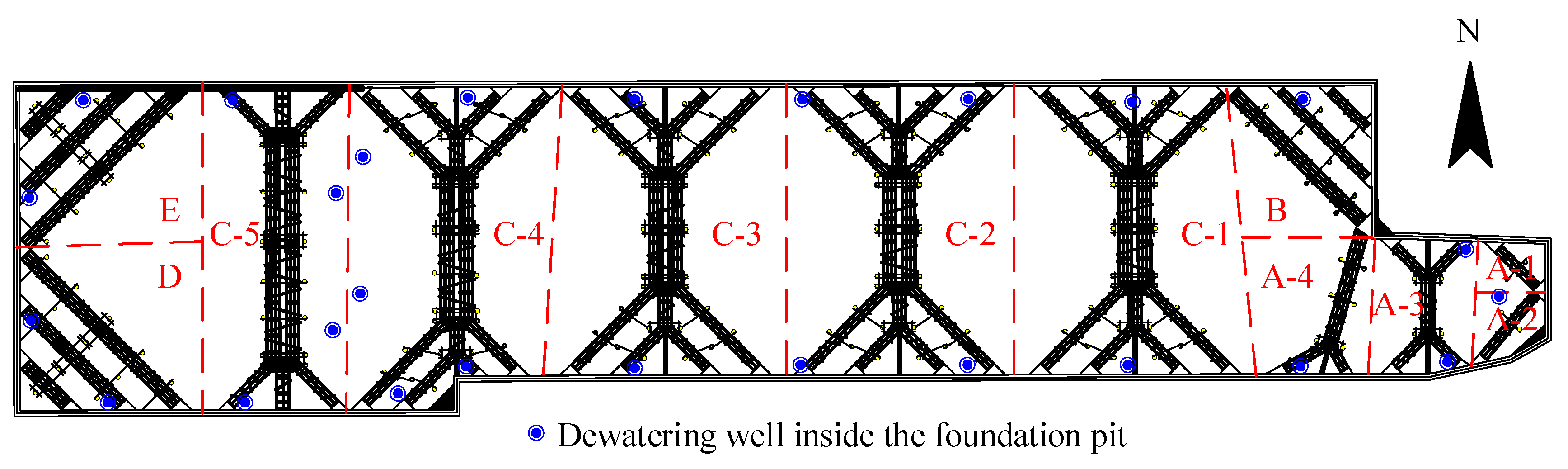
The layout plan of dewatering wells and construction zones is shown in Figure 4. A total number of 26 dewatering wells (spacing of about 40 m) are applied to control the phreatic water level at a depth of about 0.5 m beneath the excavation surface. In addition, 30 collecting wells (spacing of 30–40 m) and drainage trenches are adopted to discharge accumulated water inside the foundation pit. As the retaining structure braced with AHSS enables sub-regional support and earthwork excavation, the construction of the whole foundation pit is divided into different zones by considering the influence region of each strut. The division lines are plotted in red in Figure 4. The construction of the foundation pit started from region A1, and ended in region E. As the collapse failure was for the two levels of C1, the construction details of C1 and its adjacent regions are summarized in Table 3.
Figure 4.
Location of dewatering well and division of foundation pit.
Table 3.
Construction process of the project.
2.3. Monitoring Program
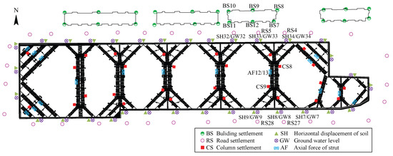
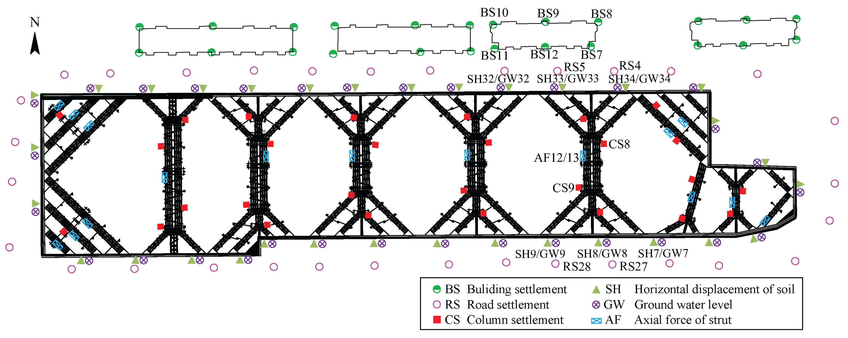
During the excavation of the foundation pit and the construction of the basement, the retaining and supporting structures and the surrounding environment are monitored. According to MHURD and SAMR [26], the monitoring items include groundwater level, axial force of strut, horizontal displacement of soil, top horizontal displacement of retaining structure, column settlement, road settlement and building settlement. The locations of monitoring points are shown in Figure 5. It should be noted that, as the collapse failure was for the two levels of C1, the monitoring points around region C-1 are specifically analyzed in the following section. According to the density requirement of monitoring points in MHURD and SAMR [26], only column 2 (CS8) and column 5 (CS9) were selected as the real-time monitoring points for column settlement. No settlement monitoring points were set up for the remaining columns. The monitoring alarm values are shown in Table 4.
Figure 5.
Location of the monitoring point.
Table 4.
Safety requirements during excavation.
3. Failure of the Foundation Pit
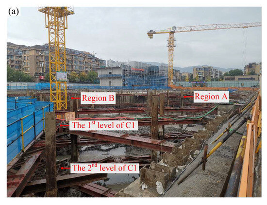
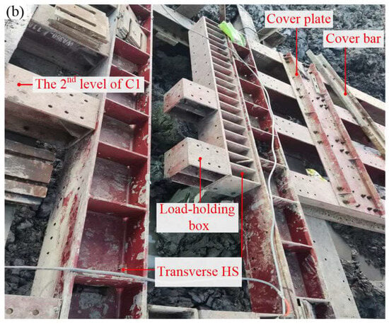
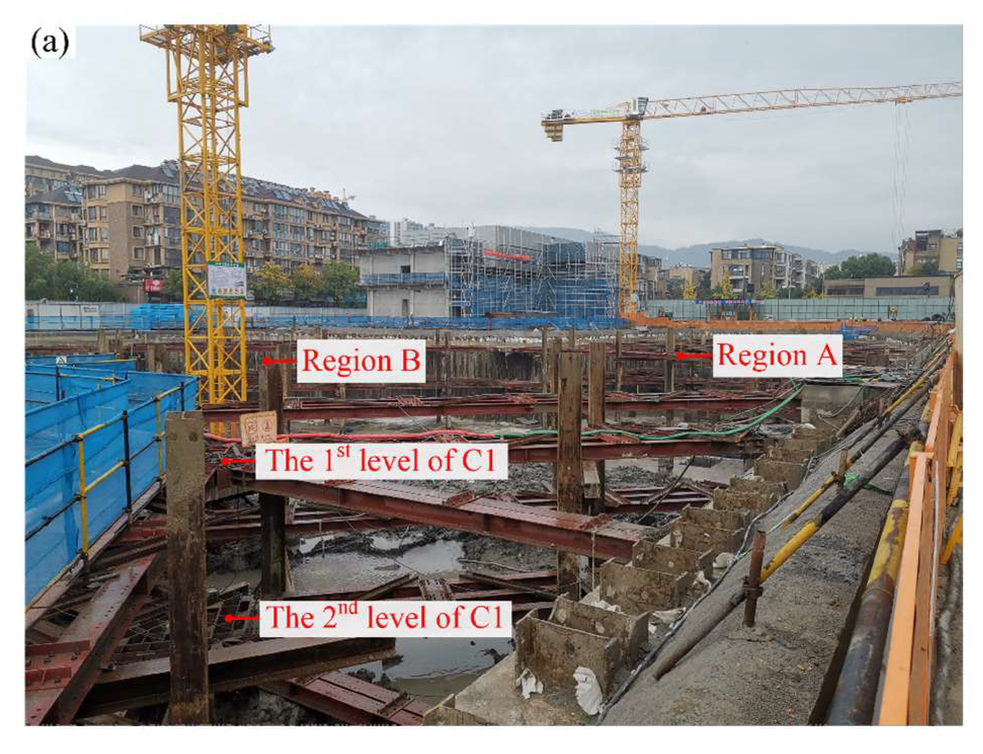
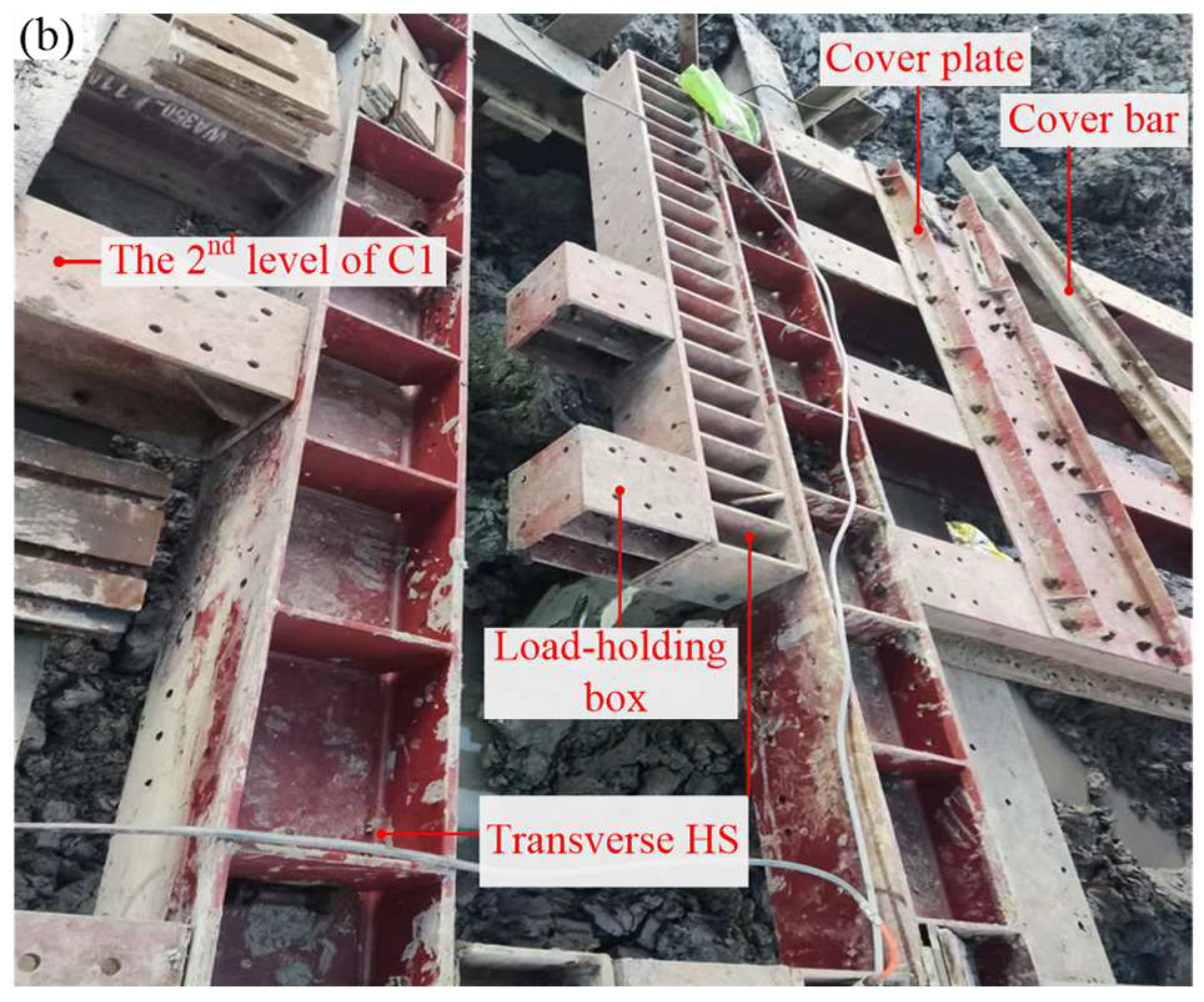
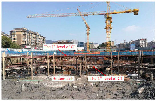
The excavation project was carried out since August 2022. Before the failure, in the morning of November 27th, the status of the foundation pit is shown in Figure 6. The bottom slab concreting in regions A-1, A-2, A-3, A-4 and east half part of region B was completed (see Figure 6a). The soil excavation started to move to the west part of region C-1. The central and north parts of region C-2 were going through surface soil excavation. The 1st level of C1, the two levels of A3, A4, B1, B2 and B3, and struts A1 and A2 all work in normal condition. The 2nd level of C1 was under assembling with the loading components left unassembled only (see Figure 6b). No construction work was carried out in other regions. All the monitoring data remained within safe condition, with no anomaly observed inside and outside the foundation pit.
Figure 6.
Photos of the foundation pit before the failure: (a) top view of C1; (b) loading components of the 2nd level of C1.
3.1. Observation of the Failure
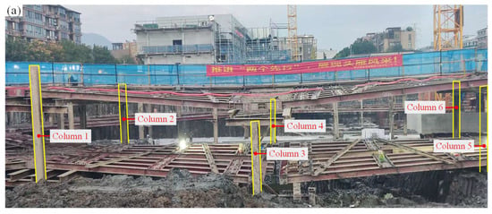
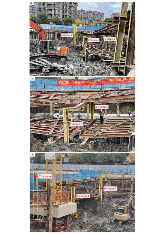
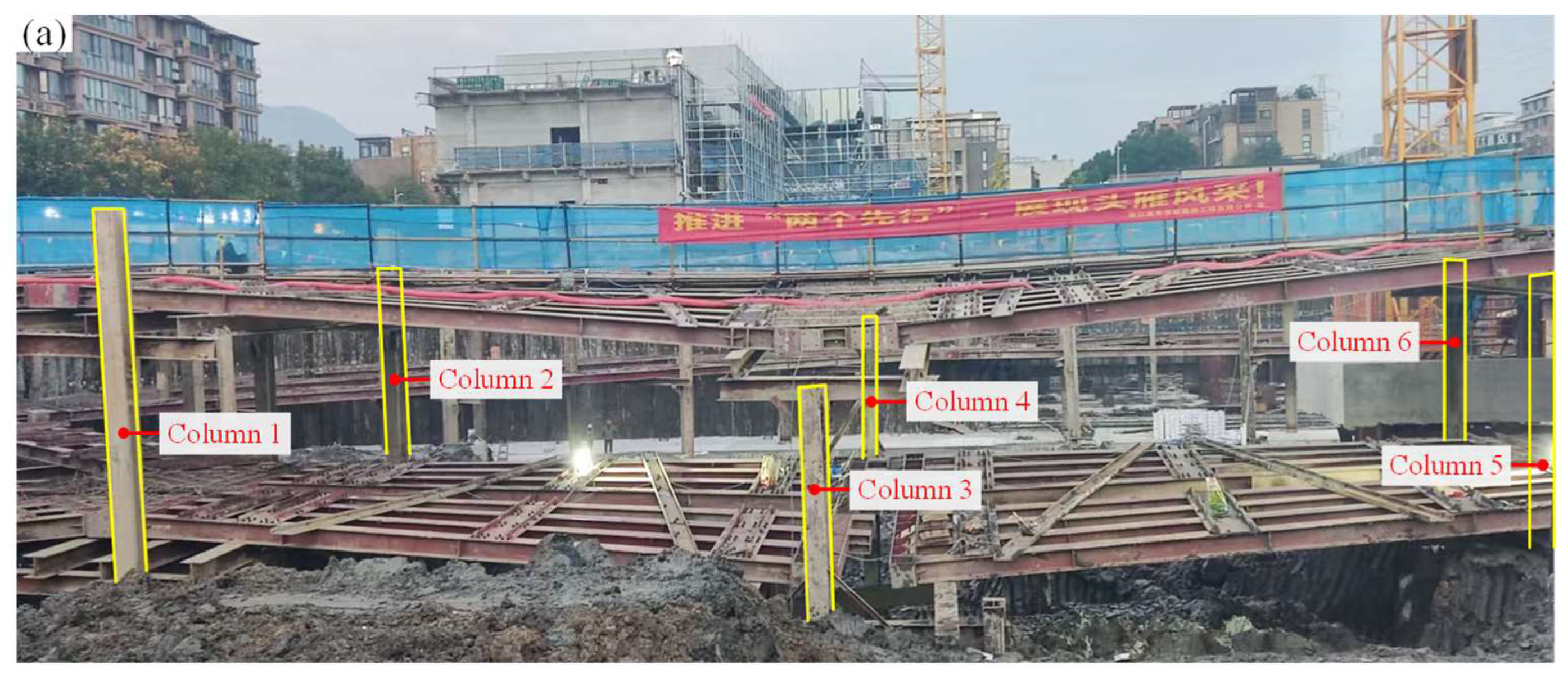
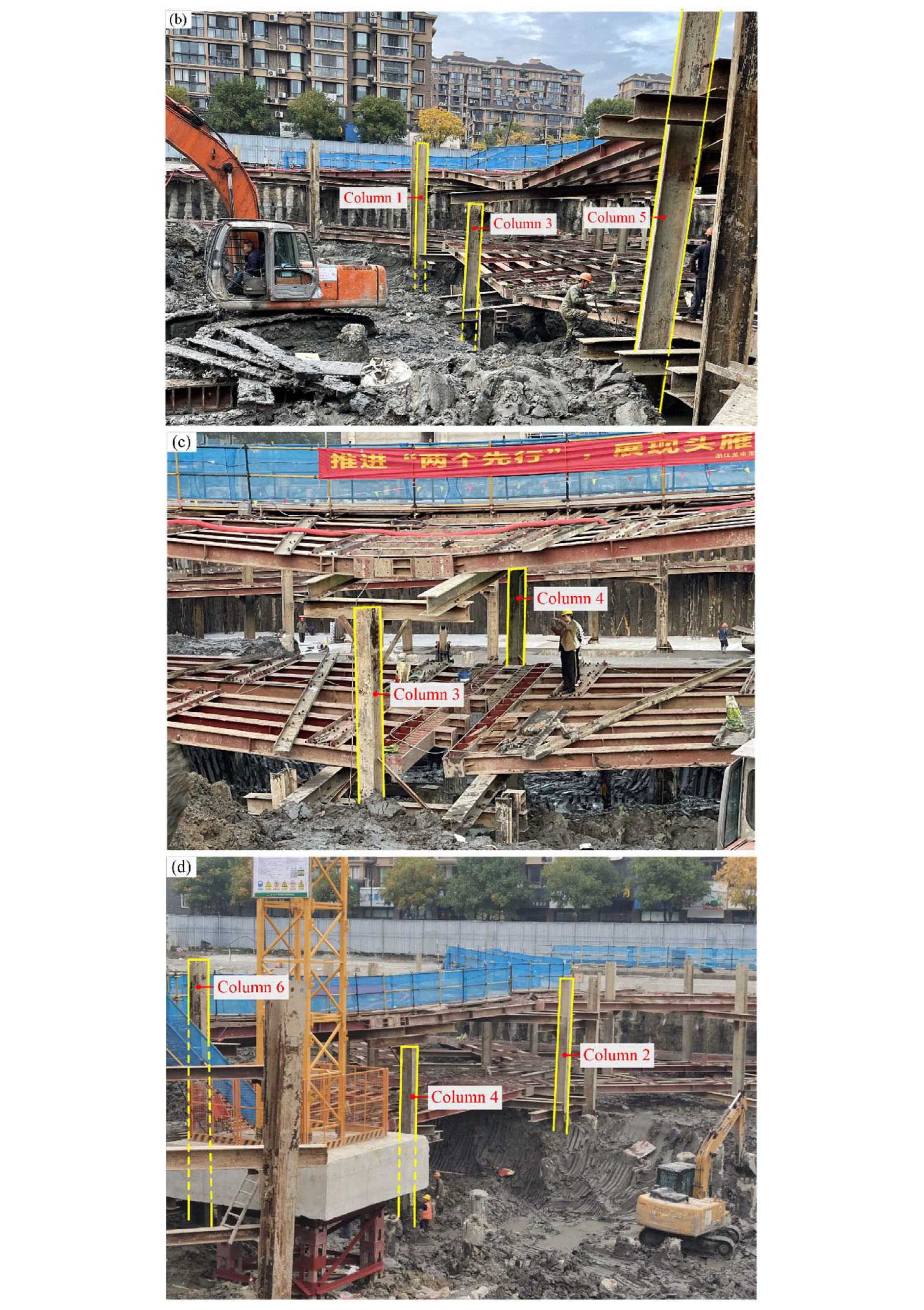
In the afternoon of 27 November, as shown in Figure 7, an unexpected collapse of the two levels of C1 happened. It should be noted that prior to and during the collapse failure, no alarm of monitoring data (see Table 4) was triggered, indicating that the foundation pit was overall in a safe condition. After the collapse of C1, construction works in the foundation pit were halted immediately, and in situ investigation was carried out.
Figure 7.
Photos of the collapsed C1: (a) west–east view; (b) south–north view; (c) local view; (d) east–west view.
For AHSS, both of the two levels of C1 collapsed. As shown in Figure 7a,b, the collapse in the middle of C1 was particularly severe. The collapse became less obvious when approaching the two ends of C1. For the rows of HS in C1, the collapse or settlement of the western rows was greater than those of the eastern rows (see Figure 7c,d). Local buckling deformation was observed in the cover plates, cover bars and high-strength bolts around the loading component in the middle of C1. No deformation or displacement was found for the other struts.
The collapse of C1 was found to be directly related to the settlement of supporting columns. Column 1–column 6 beneath the middle of C1 had settlement of 5 cm, 1 cm, 122 cm, 5 cm, 7 cm and 1 cm, respectively. The maximum settlement occurred in column 3, and was 40.7 times the alarm value of 30 mm. It should be noted that the vertical settlement of column 3 (122 cm) was not recorded by the real-time monitoring program. Instead, this value was obtained through a post-collapse emergency survey using a level instrument (Leica LS15, Leica Geosystems). The other columns had no vertical displacement and hence were still in safe condition.
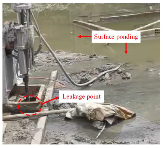
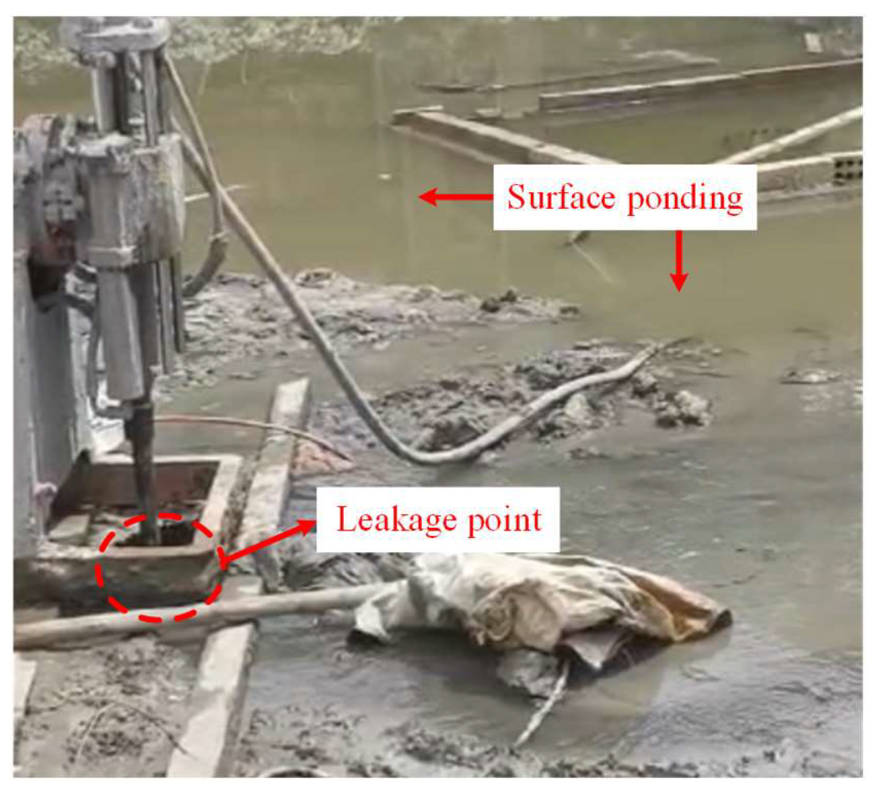
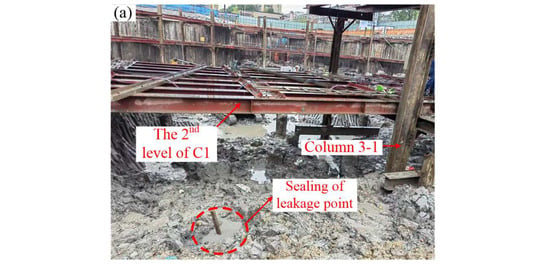
There was no obvious displacement or deformation for the retaining piles. No leakage was found through the waterproof curtains. A careful check of the excavation surface showed that all the excavation work was carried out correctly according to the designed scheme. There was no over-excavation. However, as shown in Figure 8 and Figure 9, a leakage point was identified. It was about 2.0 m and 5.0 m to the west and north of column 3, respectively. The leakage point was originally an exploration borehole. It indicated that the exploration borehole was not backfilled and sealed well and hence provided seepage channel for the confined water. The seepage rate was estimated to be about 5.0 m3/d. Based on above in situ investigations, the collapse of C1 was preliminarily attributed to column settlement, which was potentially linked to the identified leakage point. Further analysis is presented in the following section.
Figure 8.
Photo of the leakage point.
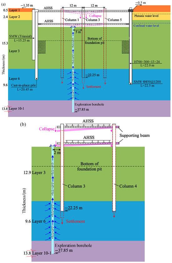
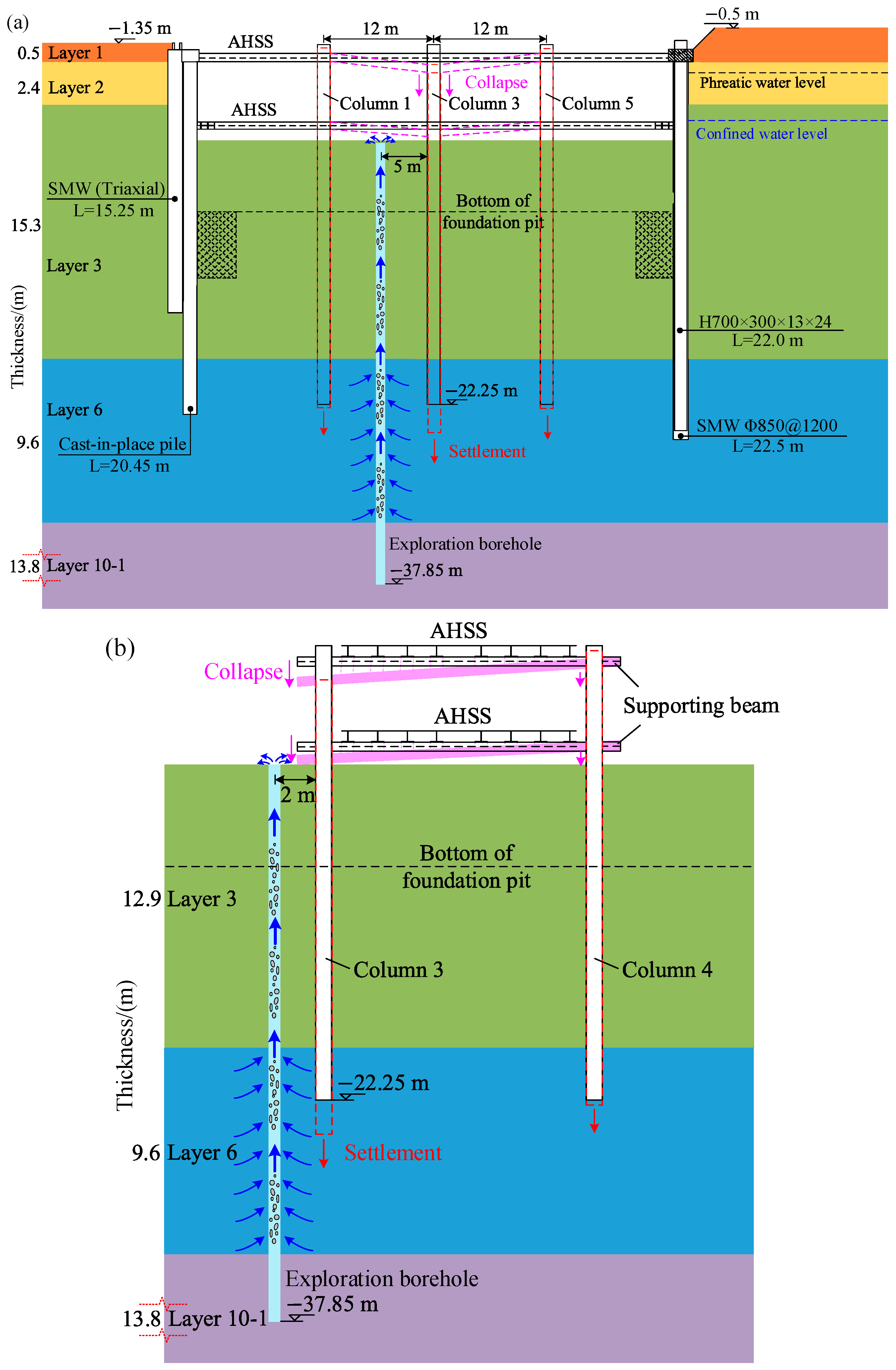
Figure 9.
Schematic diagram of the collapse failure: (a) south–north cross-section; (b) west–east cross-section (unit: m).
3.2. Evaluation of the Cause of the Failure
The collapse of C1 was directly related to the settlement of columns, which were considered to have insufficient vertical bearing capacity to support the above struts. Therefore, the vertical bearing capacity was checked. According to MHURD [27], there are:
where Fv (kN) is the vertical load acting on the column; Ra (kN) is the characteristic value of vertical bearing capacity of the column; W (kN) is the total self-weight of AHSS and supporting beam transferred to the column; Fa (kN) is the additional vertical force transferred to the column by considering the buckling deformation of AHSS; Ws (kN) is the self-weight of AHSS transferred to the column; Wb (kN) is the self-weight of supporting beam transferred to the column; Quk (kN) is the standard value of vertical bearing capacity of the column; K is the safety factor; Qsk (kN) is the standard value of total ultimate side resistance; Qpk (kN) is the standard value of total ultimate end resistance; u (m) is the column perimeter; qsik (kPa) is the standard value of the ultimate side resistance of the i-layer soil; li (m) is the thickness of the i-layer soil; qpk (kPa) is the standard value of the ultimate end resistance of the i-layer soil; and Ap (m2) is the end area of the column.
Based on the information of AHSS, supporting beam and column for C1, for each column, the values of Ws and Wb are estimated to be 129.07 kN and 27.40 kN, respectively. According to MHURD and GAQSIQ [28], the value of Fa is set as 1/60 of the maximum axial force of C1. The axial forces of the 1st and 2nd levels of C1 under the most unfavorable condition are 6229.26 kN and 11,370.08 kN, respectively. Hence, the value of Fa for each column is 146.66 kN. According to the information of column and properties of soils, the value of Qsk, Qpk and Quk are estimated to be 846.39 kN, 35.10 kN and 881.49 kN, respectively. The value of K is set as 2.0 according to MHURD [27]. It is found that the embedment depth of the column (i.e., 10.0 m in this project) is sufficient enough, as the values of Fv (i.e., 303.13 kN) and Ra (i.e., 440.75 kN) satisfy Equation (1).
Based on the above equations, it is found that, if the values of qsik and qpk are reduced to 67% of their original values (i.e., the values from geological survey report), the embedment depth of the column would be no longer safe enough. In future excavation projects located in leakage-prone strata, a 30% reduction in soil strength is suggested for the determination of column embedment depth.
As mentioned above, there was a leakage through the exploration borehole. According to Zhou and Cai [29], Xu et al. [7] and Li et al. [30], the bottom leakage could result in soil particle loss and reduced strength of adjacent soils. Furthermore, the in situ construction works also contribute to the disturbance of underlying soils. Therefore, the settlement of columns due to Fv > Ra was believed to be triggered by the bottom leakage and the construction disturbance.
A schematic view of the failure mechanism is shown in Figure 9, which include:
(i) An improperly sealed exploration borehole beside columns in the mid-span of C1 provided seepage channel for the confined water.
(ii) The water gushing through the exploration borehole resulted in soil particle loss and reduced soil strength around the columns. The columns closer to the leakage point tended to experience larger settlement. The two levels of C1 collapsed due to the settlement of columns.
(iii) The construction disturbance also contributed to the reduced bearing capacity of columns, though it was not the leading factor.
Furthermore, the monitoring layout had inherent spatial limitations, as the density of monitoring points was limited. Thus, except for the monitored column 2 and column 5, the settlement of other columns was not recorded.
4. Reconstruction of the Foundation Pit
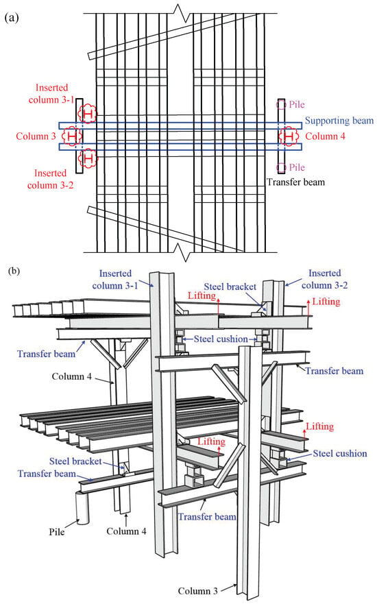
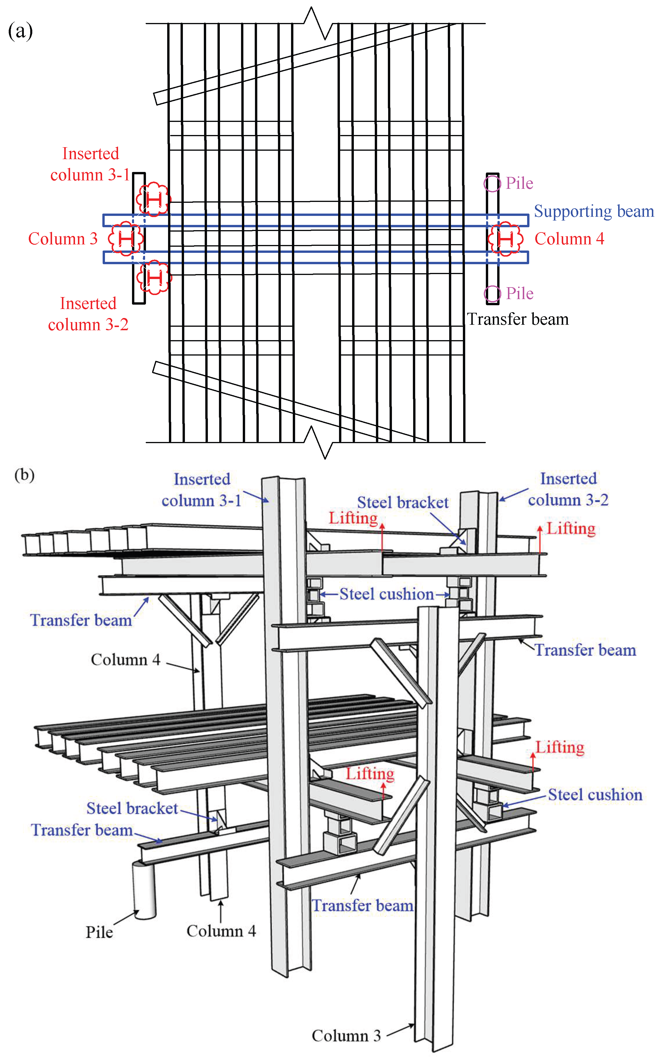
After the collapse, emergency measures were carried out immediately. First, as the 1st level of C1 could no longer support the retaining piles, soil was backfilled against the south and north retaining piles around C1. Second, in order to prevent further settlement of columns, the leakage point was sealed by two-shot grouting. Third, additional two columns were inserted next to column 3, and they helped support the transfer beam. As indicated by the monitoring data, the foundation pit was kept in a safe condition through above emergency measures.
Five steps of reconstruction work were carried out for C1 (see Figure 10):
Figure 10.
Design of the reconstruction of C1: (a) plan view; (b) stereo view.
(i) Metro Jet System (MJS) piles were applied to reinforce the soils around column 1–column 6. The pile diameter was 1200 mm, with a reinforcement depth of 18 m. The 28-day unconfined compressive strength of soil-cement sample was about 1.2 MPa.
(ii) For the columns with relatively small settlement (columns 1, 2, 4, 5 and 6), under the original transfer beam beneath the 2nd level of C1, a new transfer beam was added on top of the two piles adjacent to each column. The new transfer beam was connected to the column via steel bracket and high-strength bolts. Therefore, the two adjacent piles could help the column support the above struts.
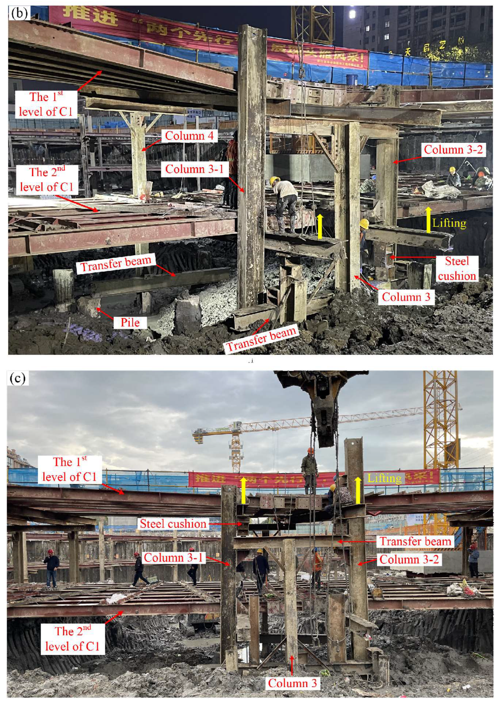
(iii) For column 3, another two new columns (H300 × 300 × 10 × 15, Q235B, embedment depth of 10 m) were inserted (see Figure 10) near column 3. They (i.e., column 3-1 and column 3-2) were about 1 m away from column 3.
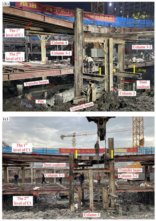
(iv) The supporting beams under the loading components in the mid-span of C1 were lifted by crawler crane. During this process, for each supporting beam, a hydraulic jack and steel cushion were filled into the gap between the supporting beam and the underlying transfer beam. The hydraulic jack was finally used to precisely jack the supporting beam and AHSS to the designed elevation. Then the steel bracket was used to connect the new column and supporting beam, and the hydraulic jack was replaced by steel cushion. Therefore, the two new columns could help column 3 support the above struts.
(v) As AHSS is assembled through steel components, after replacing the deformed components (e.g., cover plate, cover bar and bolt), the two levels of C1 were re-assembled and re-prestressed. The preloads of the 1st and 2nd levels of C1 were set as 4000 kN and 3000 kN, respectively, which were slightly above the corresponding initial designed preloads shown in Table 2, in order to control the horizontal displacement of the retaining system.
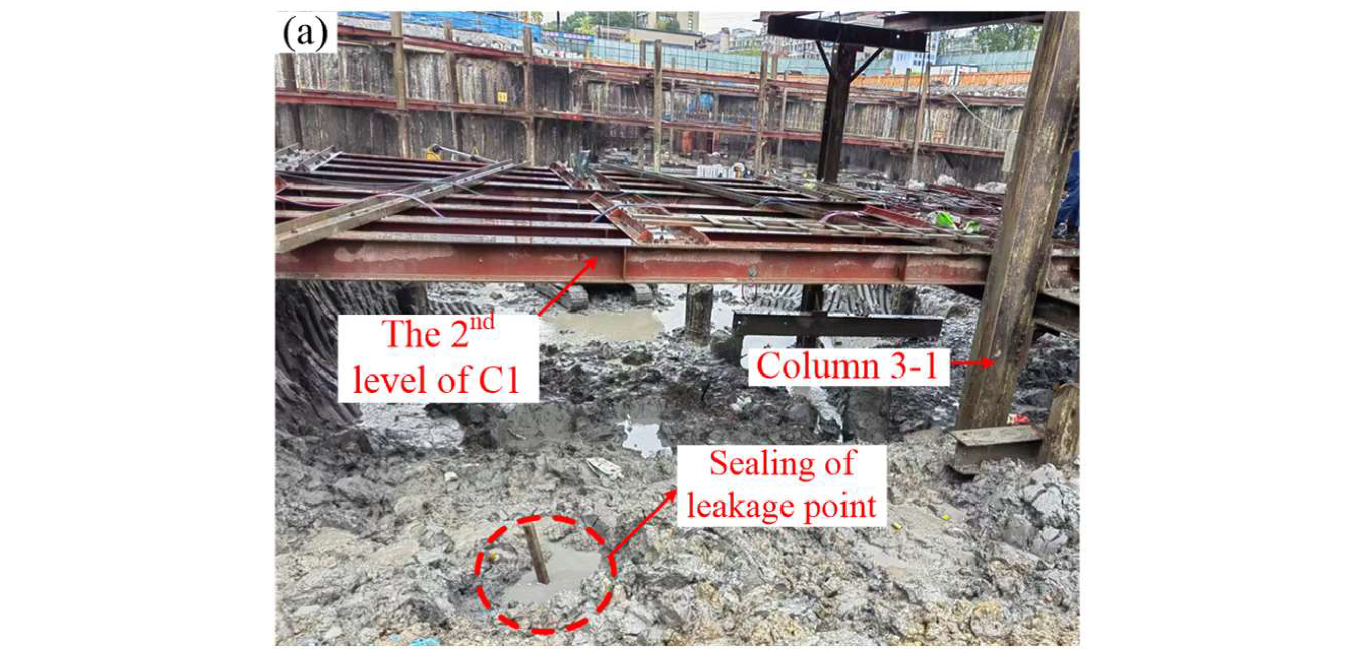
The photos of in situ reconstruction works are shown in Figure 11. They were completed within 24 h, which ensured the safety of the foundation pit.
Figure 11.
Photos of reconstruction works: (a) sealing of the leakage point; (b) lifting of the supporting beams for the 2nd level of C1; (c) lifting of the supporting beams for the 1st level of C1.
5. Pre-Assessment of the Safety of C1 After Reconstruction
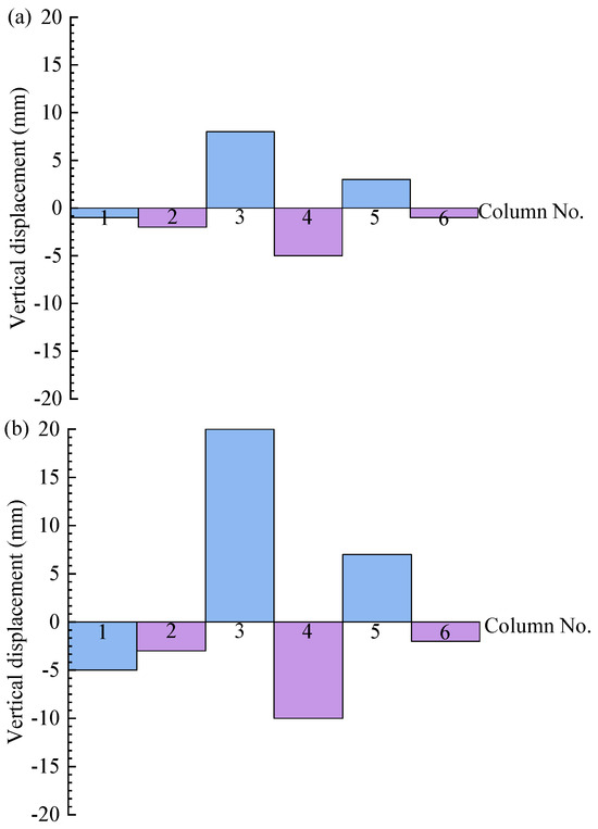
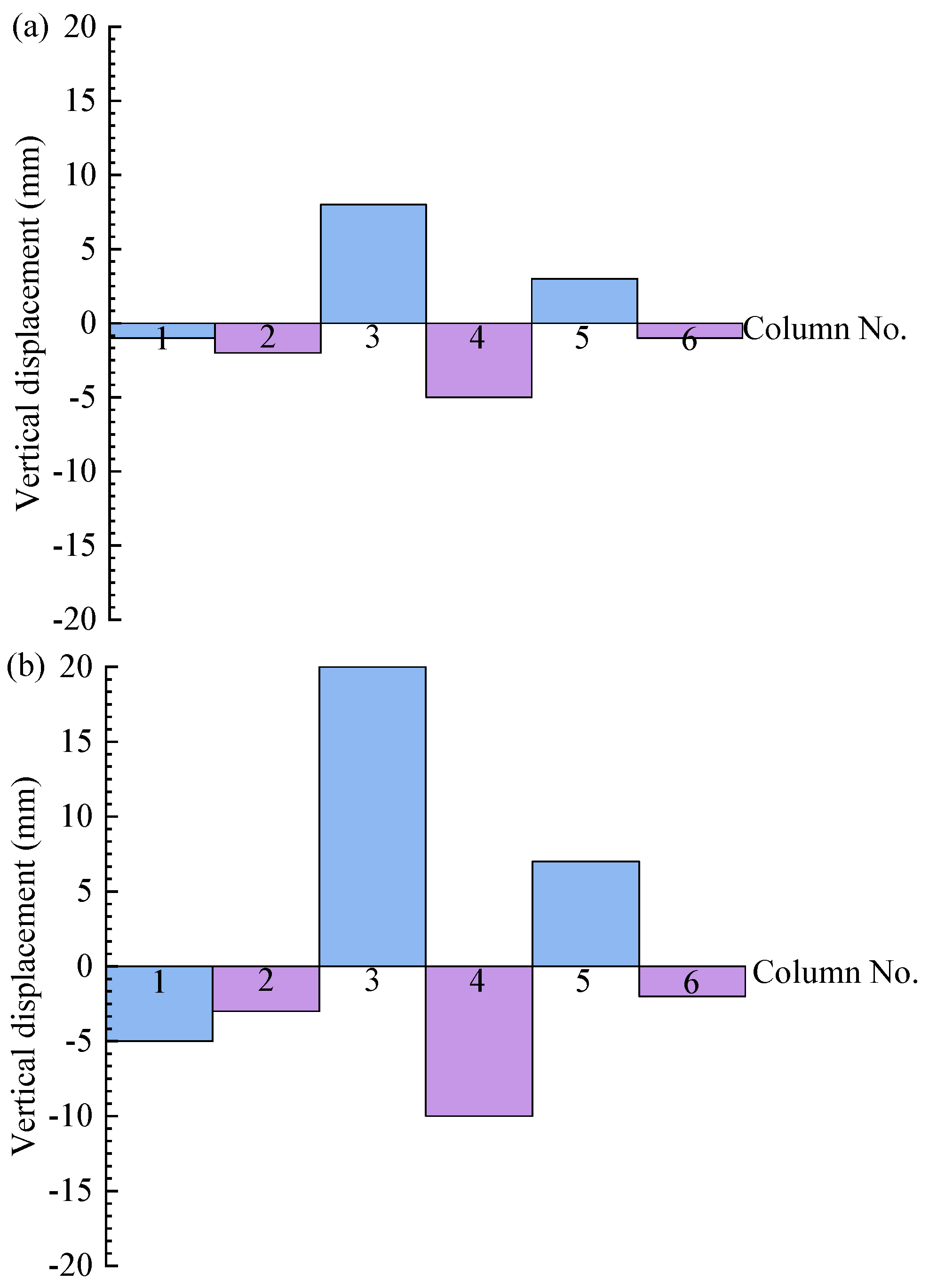
According to BHURDZ [24], the deflection of AHSS should not exceed 1/1000 of its length. For C1 (length of 64.6 m), the allowable deflection is 64.6 mm. However, according to the safety requirement shown in Table 4, the column vertical displacement should be within 20–30 mm. After the reconstruction, the vertical displacements of C1 at the positions corresponding to column 1–column 6 were re-checked, and their values are shown in Figure 12. The vertical displacements of C1 were measured using a level instrument (Leica LS15, Leica Geosystems). The positive and negative values represent uplift and settlement, respectively. It shows that, after re-preloading, the maximum uplift and settlement of the 1st level of C1 were 7.5 mm and 5.0 mm, respectively, which occurred in the positions of column 3 and column 4, respectively. The maximum uplift and settlement of the 2nd level of C1 were 25.0 mm and 10.0 mm, respectively, which also occurred in the positions of column 3 and column 4, respectively. The vertical displacements were all within 20–30 mm. It should be noted that, the slight deviation of restored elevation was caused by the replacement of hydraulic jack with several steel cushions. Keeping the hydraulic jack would be better. As the 2nd level of C1 showed more deflection and experienced greater axial force than the 1st level, theoretical and numerical analysis were conducted to study its working performance by considering the above deflections.
Figure 12.
Vertical displacement of C1 after reconstruction: (a) the 1st level; (b) the 2nd level.
5.1. Theoretical Analysis
According to DHURDZ [31], the strength and stability of AHSS should satisfy:
where N (N) is the designed axial compressive force of strut; An (m2) and A (m2) are the net and gross cross-sectional areas of strut, respectively; Mx (N·m) and My (N·m) are the designed moments in axes x and y, respectively; Wnx (m3) and Wny (m3) are the net cross-sectional moduli in axes x and y, respectively; f (Pa) is the designed strength of steel; φx and φy are the axial compression stability factors of strut in axes x and y, respectively, and can refer to the MHURD and GAQSIQ [28]; Wx (m3) and Wy (m3) are the gross cross-sectional moduli in axes x and y, respectively; and N’Ex and N’Ey are:
where E (Pa) is the elastic modulus of steel; λx and λy are the slenderness ratios in axes x and y, respectively:
where l0x (m) and l0y (m) are the effective lengths in axes x and y, respectively; ix (m) and iy (m) are the gyration radii in axes x and y, respectively. According to MHURD, GAQSIQ [28] and DHURDZ [31], the values of l0x and l0y are equal to the horizontal spacing of the supporting beam and the total length of AHSS, respectively.
According to DHURDZ [31], the safety redundancy factor is defined as the ratio of the designed strength of steel (i.e., f, the right side of Equations (6)–(8)) to the calculated maximum combined stress (i.e., the left side of Equations (6)–(8)). Based on the information of the 2nd level of C1 (see Table 5), considering the maximum deflection of 20 mm and the maximum axial force of 11,370.08 kN, the safety redundancy factors for strength, in-plane stability and out-of-plane stability are 2.81, 2.19 and 3.03, respectively. These values were much greater than the safety requirement of 1.20, indicating good overall working performance of the strut.
Table 5.
Properties of C1.
5.2. Finite Element Analysis
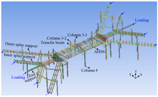
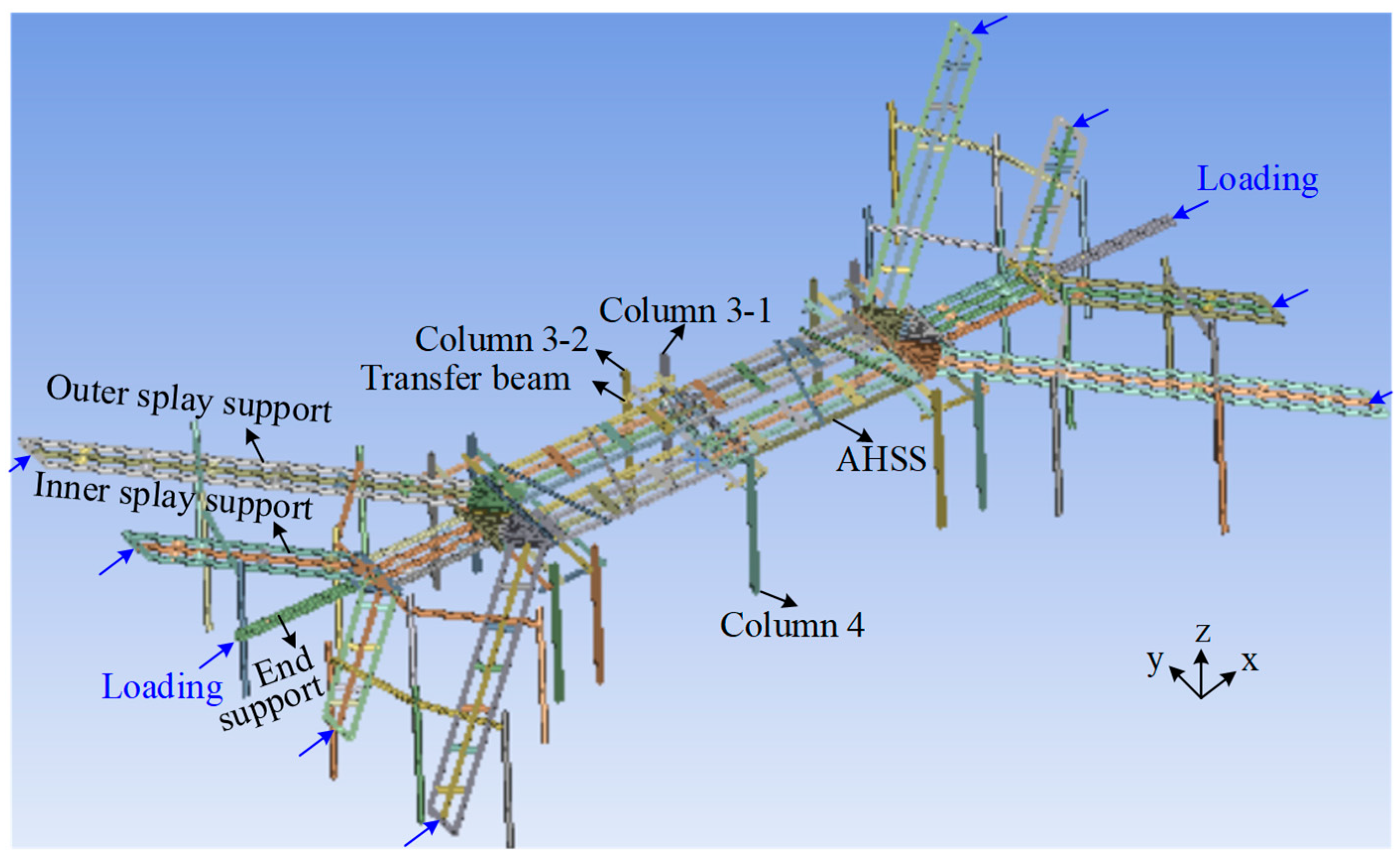
As the AHSS acts as a compressive structure under ideal conditions, the most unfavorable condition is considered to be under the maximum deflection and the maximum axial force. To evaluate the safety of each steel component and each bolt under the most unfavorable condition, numerical analysis was carried out by establishing the refined finite element model for the 2nd level of C1.
The finite element model was created by importing the BIM model of the 2nd level of C1 into ANSYS Workbench 2022 R1 (see Figure 13). The in situ axial loading test of Xu et al. [32] on AHSS with double-splay supports indicated that the outer splay supports, inner splay supports and end support carried 48.5%, 35.6% and 15.9% of the total axial force, respectively. As their AHSS had the same geometric configuration of double-splay supports with that in C1, the above load distribution ratios were applied in this study. Therefore, for the 2nd level of C1, the horizontal loads of 2757.26 kN, 2023.87 kN and 1807.84 kN were applied for each outer splay support, each inner splay support and end support, respectively. These applied loads correspond to a total axial force of 11,370.08 kN. According to MHURD [33], the bolt pretightening force was set as 250 kN. The ends of the outer splay supports, inner splay supports and end support were fixed in directions of y and z. The deflections shown in Figure 12b were applied at the bottoms of column 1–column 6 as given vertical displacement boundary. The bottoms of other columns were all fixed. Therefore, the above boundary conditions correspond to the most unfavorable condition.
Figure 13.
Finite element model of the 2nd level of C1.
According to BHURDZ [24], the rows of HS in AHSS, supporting beam, transfer beam and column all used beam element. The cover plate, cover bar, steel bracket and high-strength bolts all used solid elements. The mesh size of the spliced joints and bolts was refined to 6 mm. The remaining area was modeled with a mesh size of 24 mm. By applying the above element type and mesh size, the numerical simulation focused on the global deformation of steel components and local stress of spliced joints and bolts.
All the steel components and high-strength bolts were modeled by elastic–plastic constitutive law for steel according to MHURD and GAQSIQ [28]. Hard contact was applied for the interface between bolt hole and bolt shank, which means the normal penetration is restricted and the tangential friction is neglected. Other interfaces between steel components used frictional contact, which has a friction coefficient of 0.30. The supporting beam, transfer beam, column, steel bracket, cover plate and cover bar use Q235B steel. The rows of HS, transverse HS and load-holding box use Q355B steel. M24 high-strength bolt of Class 10.9 is used to connect all the steel components.
Their properties are listed in Table 6. The simulation results are shown in Table 7. The maximum in-plane positive and negative displacements are 3.73 mm and −3.90 mm, respectively. The maximum out-of-plane positive and negative displacements are 24.06 mm and −25.79 mm, respectively. Therefore, the horizontal displacements of the 2nd level of C1 are quite small and acceptable, and the vertical displacements meet the required safety value of 20–30 mm. The maximum von Mises stresses of supporting beam, column, steel bracket, cover plate and cover bar are 115.9 MPa, 43.3 MPa, 181.0 MPa, 37.6 MPa, 37.6 MPa, respectively. All of these are less than the yield strength of 235 MPa, and they are only approximately 16.0%, 16.0%, 18.4%, 49.3% and 77.0% of the yield strength, respectively. The maximum von Mises stresses of rows of HS, transverse HS and load-holding box are 189.6 MPa, 156.0 MPa and 147.0 MPa, respectively. All of these are smaller than the yield strength of 355 MPa, and they are only approximately 53.4%, 43.9% and 41.4% of the yield strength, respectively. The maximum von Mises stress of bolt is 333.2 MPa, which is smaller than its yield strength of 940 MPa and is only approximately 35.4% of yield strength. Therefore, all the steel components and bolts of the 2nd level of C1 are in safe condition.
Table 6.
Properties of steel components.
Table 7.
Simulation results of the 2nd level of C1.
6. Status of the Foundation Pit After the Reconstruction of C1
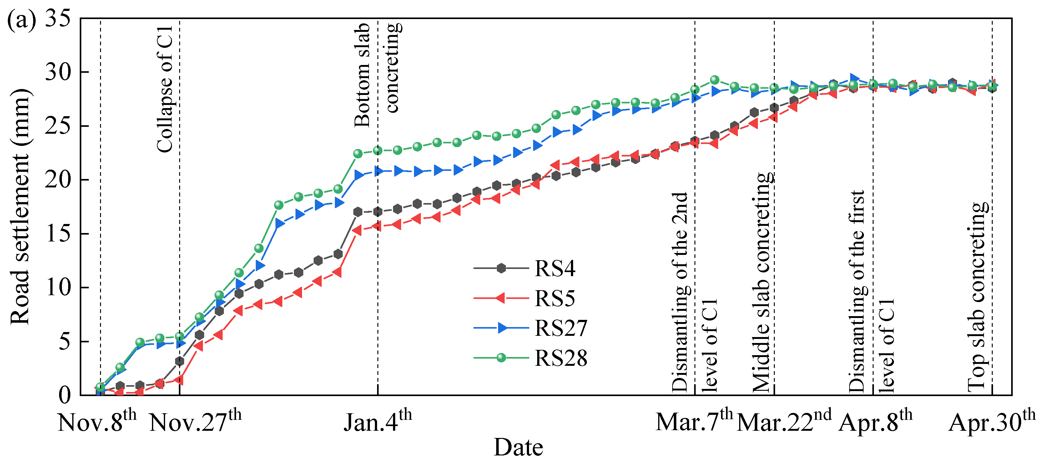
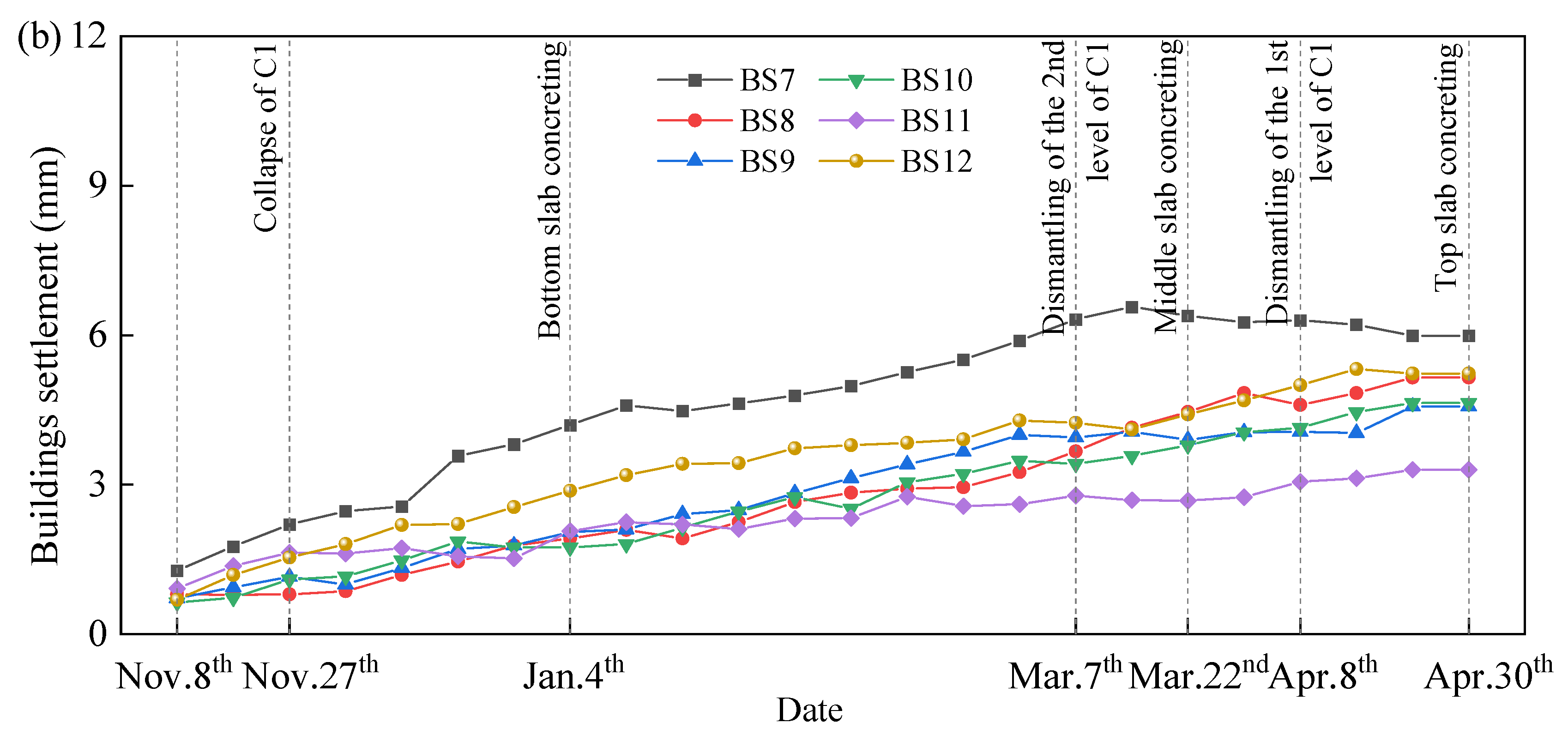
The photo of region C-1 after the reconstruction of C1 is shown in Figure 14. The results of monitoring points near region C-1 after the reconstruction of C1 are shown in Figure 15, Figure 16, Figure 17, Figure 18 and Figure 19.
Figure 14.
Bottom slab construction beneath C1.
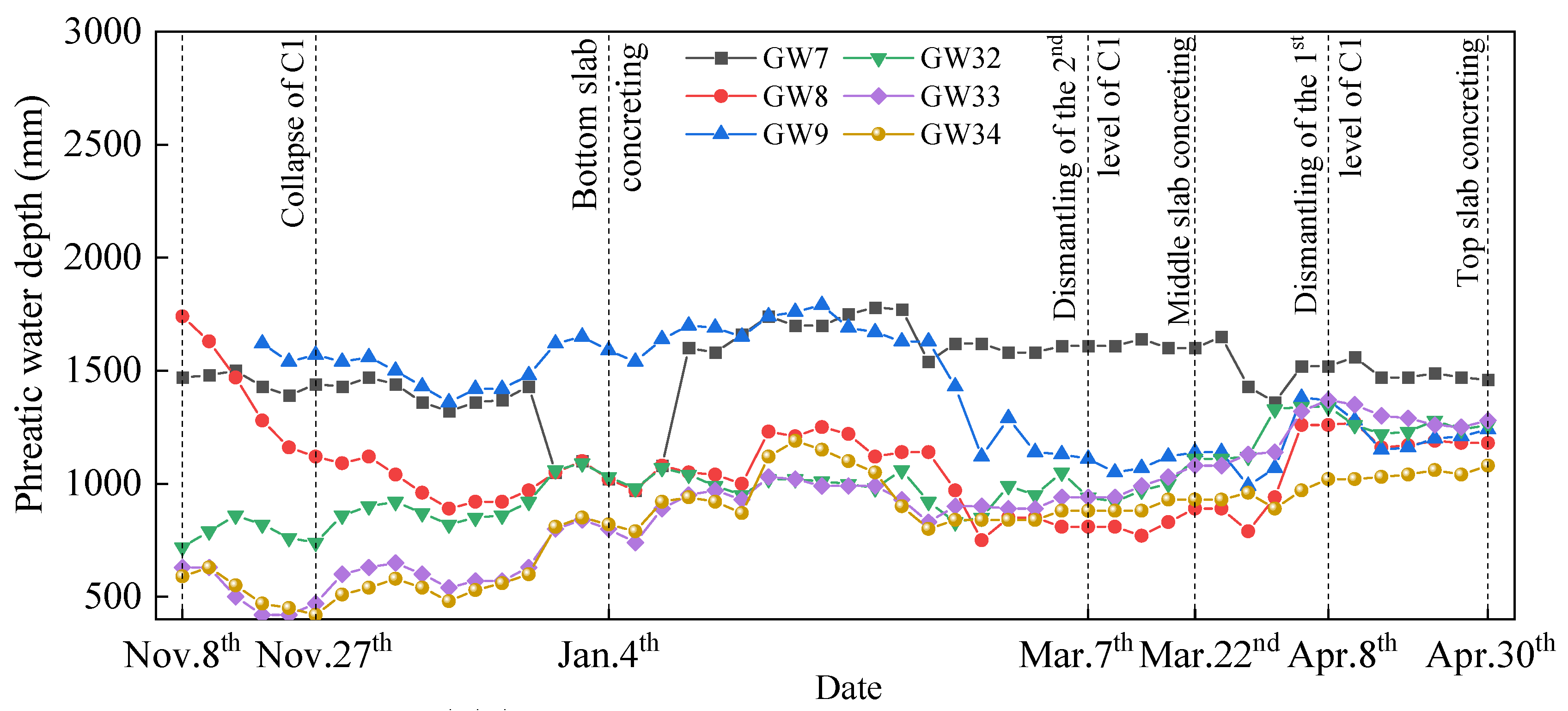
Figure 15.
Monitored phreatic water level.
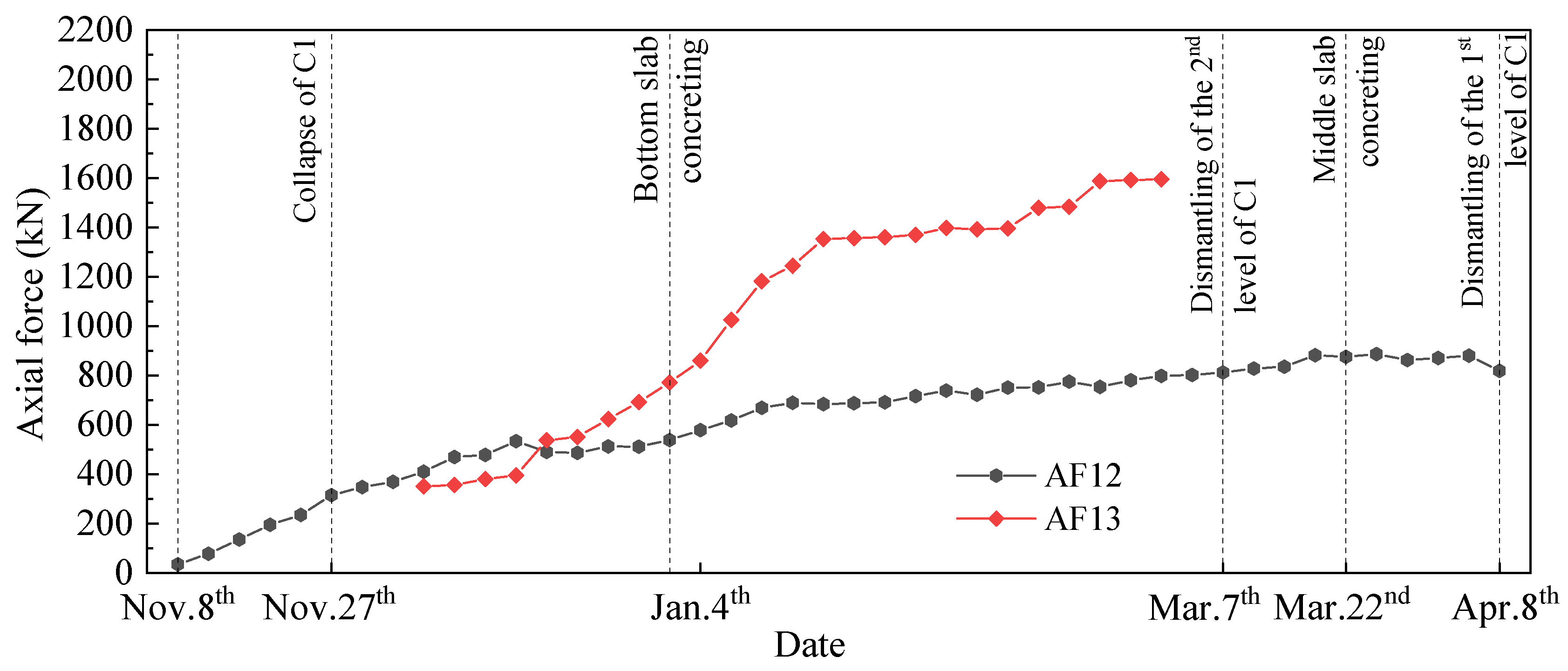
Figure 16.
Monitored axial force of strut.
Figure 17.
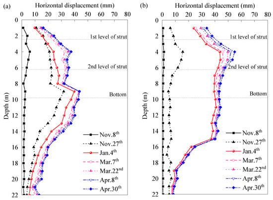
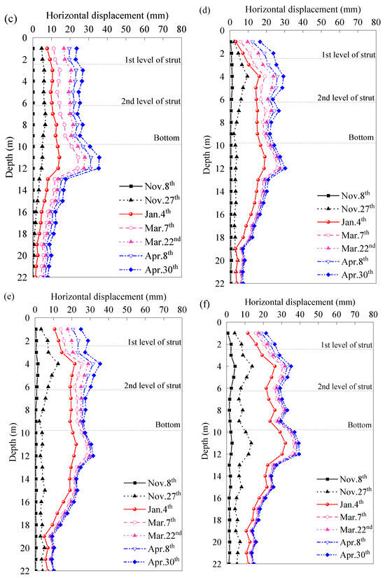
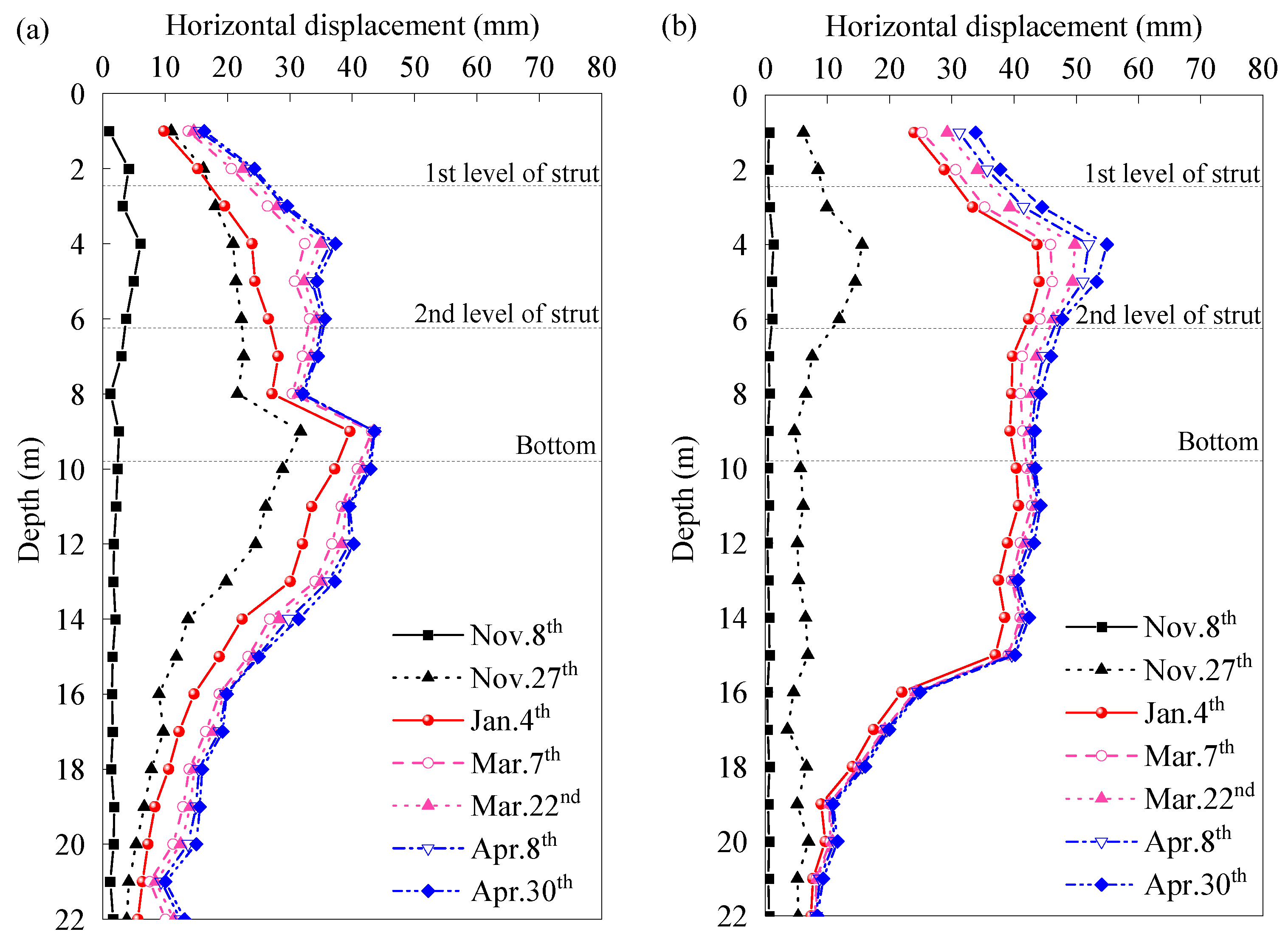
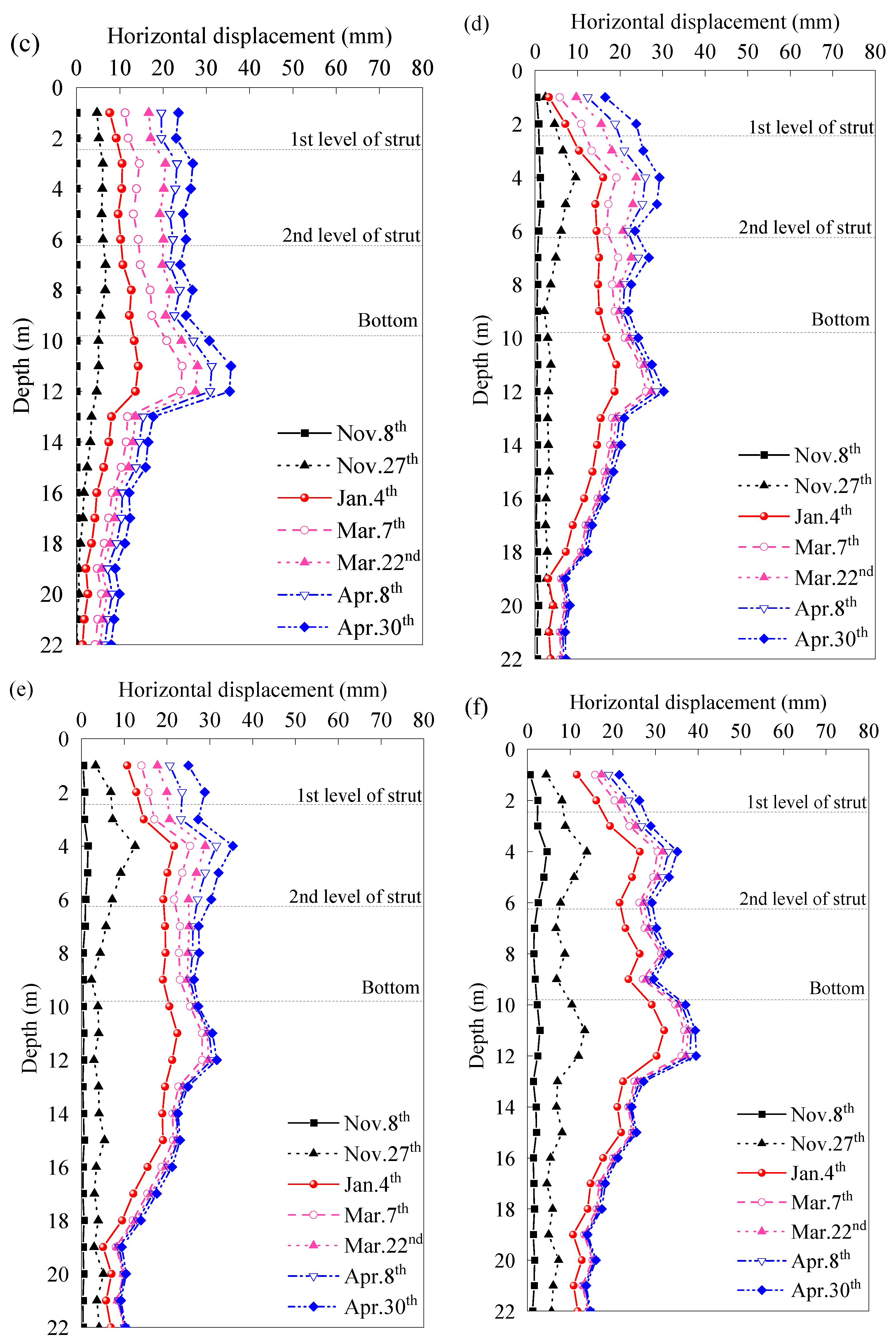
Monitored horizontal displacement of soil: (a) SH7; (b) SH8; (c) SH9; (d) SH32; (e) SH33; (f) SH34.
Figure 18.
Monitored vertical displacement of column.
Figure 19.
Monitored settlement of surrounding environment: (a) road; (b) building.
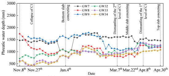
The monitored depth of phreatic water outside the foundation pit is shown in Figure 15. During the subsequent soil excavation after the reconstruction of C1, GW7–GW9 and GW32–GW34 near C1 tended to increase slightly. After the completion of bottom slab, the phreatic water levels showed slight fluctuation during the dismantling of C1 and the construction of basement. They were generally around a depth of 750–1800 mm in the early stage (i.e., 4 January–8 April ) and 1000–1500 mm in the later stage (i.e., 8–30 April). Therefore, the effect of the variation in phreatic water level on the lateral earth–water pressure acting on the retaining structure was considered to be small.
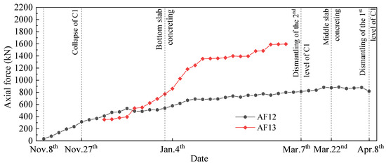
The monitored axial forces of C1 are shown in Figure 16. AF 12 and AF13 represented the axial forces of outer row of HS in the middle region of the 1st and 2nd levels of C1, respectively. As each level of C1 consisted of eight rows of HS, the total axial forces of the 1st and 2nd levels were estimated to be eight times the values of AF12 and AF13, respectively. After the reconstruction of C1, the axial force of the 1st level of C1 increased from 3280 kN to 5352 kN during the subsequent soil excavation. The axial force of the 2nd level of C1 showed more obvious increase from 2800 kN to 9456 kN during the subsequent soil excavation. They both showed slight increase during the construction of basement. When the struts were dismantled, the maximum axial forces of the 1st and 2nd levels of C1 were about 6552 kN and 12,763.6 kN, respectively, both below the required safety value of 16,448.99 kN.
The monitored horizontal displacements of soil are shown in Figure 17. After the reconstruction of C1, an increase in horizontal displacement was observed in the deep soil. The increase was relatively larger during the subsequent soil excavation before the completion of bottom slab, as compared to that during the dismantling of C1 and the construction of basement. Especially for SH8 which was close to the south end of C1, the significant increase in horizontal displacement during the subsequent soil excavation was due to the place for soil outlet over there. Overall, the largest horizontal displacement of soil occurred at two locations including the position between the 1st and 2nd levels of C1 and the position around the bottom of foundation pit. After the completion of top slab of basement, the maximum horizontal displacements for SH7–SH9 and SH32–SH34 were around 30.2–54.9 mm. Only the maximum horizontal displacement of SH8 (i.e., 54.9 mm, which was about 5‰ of the excavation depth) exceeded the requirement of 45 mm, and those of others were all smaller than 45 mm.
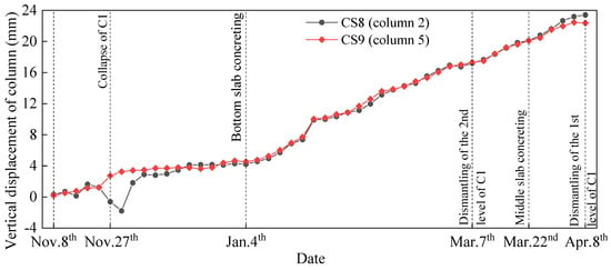
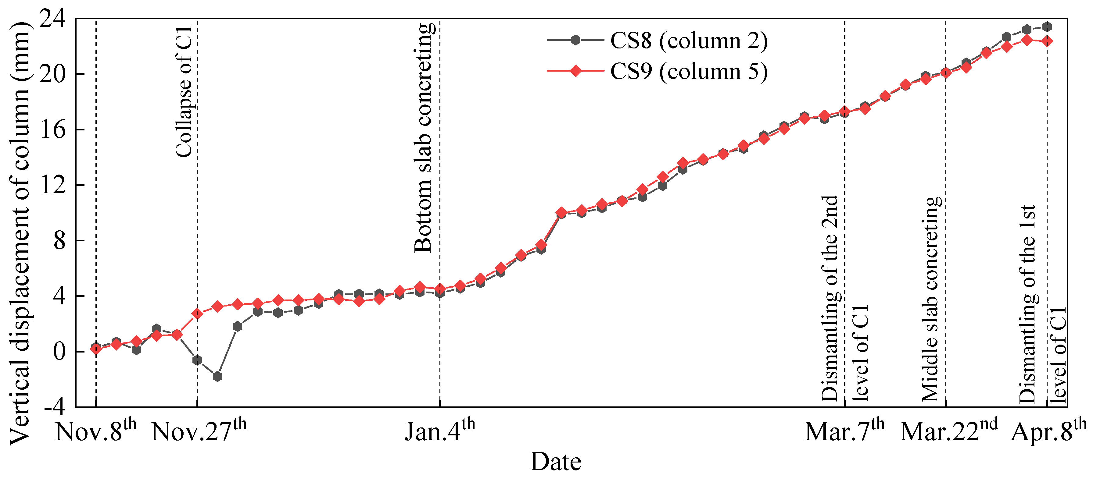
The monitored vertical displacements of columns are shown in Figure 18. CS8 and CS9 correspond to column 2 and column 5 in Figure 7, respectively. As mentioned above, when C1 collapsed, column 2 and column 5 showed slight settlement (i.e., about −2 mm) and uplift (i.e., about 3 mm), respectively. After the reconstruction of C1, during the subsequent soil excavation and basement construction, both column 2 and column 5 tended to show increasing uplift with time. When C1 was dismantled, the final uplifts of column 2 and column 5 were about 23.4 mm and 22.3 mm, respectively, which were smaller than the required safety value of 30 mm.
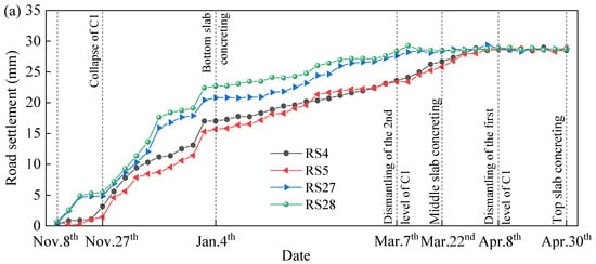
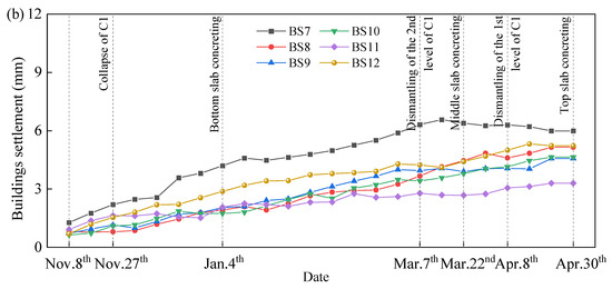
The monitored settlements of road and building are shown in Figure 19. The road next to C1 showed increasing settlement during the subsequent soil excavation before the completion of bottom slab. The road outside the south end of C1 (i.e., RS27 and RS28) tended to have greater settlement than that outside the north end of C1 (i.e., RS4 and RS5). It was mainly due to the soil outlet set at the south end of C1. The increasing rate of road settlement became smaller during the construction of basement. After the dismantling of C1, the road settlements became stable, which had similar maximum value of about 29 mm. The settlement of building next to the north end of C1 showed an increasing trend with the subsequent soil excavation and basement construction. The relatively large settlement occurred at BS7 and BS12, which were closer to the north end of C1 than the other monitoring points. The maximum settlement was about 6.6 mm, which occurred at BS7 when C1 was dismantled. The road settlement and building settlement met the safety requirements of 30 mm and 15 mm, respectively.
7. Conclusions
This study investigated the collapse and reconstruction of AHSS in a deep excavation project. The main conclusions are summarized as follows:
(1) The collapse of two levels of AHSS C1 resulted directly from the settlement of columns in the mid-span of C1. The settlement of columns was caused by the water gushing through a nearby exploration borehole, which was improperly sealed and provided a seepage channel for the confined water.
(2) Emergency measures including the backfill of soil against the south and north retaining piles around C1, the sealing of leakage point by two-shot grouting, and the insertion of two additional columns next to column 3 were carried out. They were found to be effective in keeping the foundation pit in a safe condition.
(3) The reconstruction works of C1 included the reinforcement of soils around column 1–column 6 through MJS piles, the addition of transfer beams for the columns with relatively small settlement (columns 1, 2, 4, 5 and 6), the addition of two new columns for column 3, the lift of supporting beams under the loading components in the mid-span of C1, and the re-assembling and re-preloading of C1.
(4) Theoretical and numerical pre-assessments of the working performance indicated that C1 exhibited sufficient structural safety after its reconstruction. The monitoring results of the foundation pit during the subsequent soil excavation and basement construction around C1 verified the good working performance of C1.
(5) The emergency measures and reconstruction schemes provided guidance for future excavation projects facing similar problems. Although the collapse of C1 did not result in catastrophic secondary consequences, the engineers should pay attention to the safe control of ground water, especially the strict sealing of potential leakage channels.
Author Contributions
Conceptualization and methodology, M.W. and Y.L.; software and validation, X.X., Q.H. and G.C.; writing—original draft preparation, X.X.; writing—review and editing, M.W. and Y.L.; supervision, Y.L. and G.C. All authors have read and agreed to the published version of the manuscript.
Funding
The work was supported by the Construction Research Project of Zhejiang (Grant No. 2024K222) and Research Funding of Zhejiang Huadong Geotechnical Investigation and Design Institute Co., Ltd.
Data Availability Statement
The original contributions presented in this study are included in the article. Further inquiries can be directed to the corresponding author.
Conflicts of Interest
Authors Mingyuan Wang and Gang Chen are employed by the Zhejiang Huadong Geotechnical Investigation and Design Institute Co., Ltd. Author Qi Hu is employed by the Dongtong Geotechnical Technology Co., Ltd. The remaining authors declare that the research was conducted in the absence of any commercial or financial relationships that could be construed as a potential conflict of interest.
References
- Wang, W.D. Analytical methods and controlling techniques for deformation and environmental influence of deep excavations in soft soils. Chin. J. Geotech. Eng. 2024, 46, 1–25. [Google Scholar]
- Magnus, R.; The, C.L.; Lau, J.M. Report of the Committee of Inquiry into the Incident at the MRT Circle Line Worksite that Led to Collapse of Nicoll Highway on 20 April 2004; Ministry of Manpower: Singapore, 2005. [Google Scholar]
- Chen, R.P.; Li, Z.C.; Chen, Y.M.; Ou, C.Y.; Hu, Q.; Rao, M. Failure investigation at a collapsed deep excavation in very sensitive organic soft clay. J. Perform. Constr. Facil. 2015, 29, 04014078. [Google Scholar] [CrossRef] [Scilit]
- Feng, S.; Lu, S. Failure of a retaining structure in a metro station excavation in Nanchang City, China. J. Perform. Constr. Facil. 2016, 30, 04015097. [Google Scholar] [CrossRef] [Scilit]
- Tan, Y.; Jiang, W.Z.; Luo, W.J.; Lu, Y.; Xu, C.J. Longitudinal sliding event during excavation of Feng-Qi Station of Hangzhou Metro Line 1: Postfailure investigation. J. Perform. Constr. Facil. 2018, 32, 04018039. [Google Scholar] [CrossRef] [Scilit]
- Lu, Y.; Tan, Y. Overview of typical excavation failures in China. In Geo-Congress 2019: Soil Erosion, Underground Engineering, and Risk Assessment (GSP 313); American Society of Civil Engineers: Reston, VA, USA, 2019; pp. 315–332. [Google Scholar]
- Xu, X.B.; Hu, Q.; Huang, T.M.; Chen, Y.; Shen, W.M.; Hu, M.Y. Seepage failure of a foundation pit with confined aquifer layers and its reconstruction. Eng. Fail. Anal. 2022, 138, 106366. [Google Scholar] [CrossRef] [Scilit]
- Yi, F.; Zheng, G.; Cheng, X.S.; Huang, T.M.; Jia, J.W.; Wang, Z.H. Progressive collapse analysis of the corner strut subsystem in a propped excavation with inadequate system safety performance. Eng. Fail. Anal. 2024, 160, 108231. [Google Scholar] [CrossRef] [Scilit]
- Peng, Y.S.; Cao, C.Y.; Ji, F.L.; Chen, X.S. Water inrush-induced failure during deep excavation for a metro station in karst regions in Shenzhen, China: Cause diagnosis and post-accident restoration. Eng. Fail. Anal. 2024, 162, 108346. [Google Scholar] [CrossRef] [Scilit]
- Zhang, W. Case history of a design example of a deep excavation supporting beam in Wuhan. Soil Eng. Found. 2023, 37, 723–726. [Google Scholar]
- Zhou, Y.; Yang, S.; Wang, S.; Xu, M.; Zhou, H. Analysis and treatment for collapse accident of a foundation pit in deep and thick sullage soft-soil area. Build. Struct. 2024, 54, 128–135. [Google Scholar]
- Huang, L.; Xu, Y.; Zhou, K.; Wang, G. Analysis on the collapse causes of foundation pit under complex environmental in soft soil areas. Chin. J. Undergr. Space Eng. 2024, 20, 1039–1050. [Google Scholar]
- Xue, L.; Yang, W.; Li, R. Discussion and analysis of accident reasons of deep foundation pits. Chin. J. Geotech. Eng. 2013, 35, 468–473. [Google Scholar]
- Zhou, Y.; Du, L. Rethinking the treatment method of foundation pits hazards during the construction of metro stations. Mod. Urban. Transit. 2024, 4, 63–67. [Google Scholar]
- Zhu, Z. Cause analysis and reinforcement measures for the dangerous situation of the deviation of the super-large foundation pit support structure in a deep soft soil layer. Guangzhou Archit. 2024, 52, 16–21. [Google Scholar]
- Dang, H.P.; Lin, H.D.; Kung, J.H.S.; Wang, C.C. Deformation behavior analyses of braced excavation considering adjacent structure by user-defined soil models. J. Geoengin. 2012, 7, 13–20. [Google Scholar]
- Li, Y.; Chen, D.; Liu, X.; Zhu, H.; Tang, D. Application of prestressed assemble steel support system in retaining structures for foundation pits in soft soils. Chin. J. Geotech. Eng. 2014, 36, 51–55. [Google Scholar]
- Kim, S.; Whang, S.W.; Lee, Y.D.; Shin, Y.; Kim, G.H. Comparison of high-strength steel pipe and H-shaped steel in the strut of a braced wall system. J. Asian Archit. Build. Eng. 2017, 16, 179–184. [Google Scholar] [CrossRef] [Scilit]
- Hu, Q.; Shi, J.; Huang, T.; Fang, H.; Li, J.; Chen, Y.; Zhang, K. Experimental study on prestressed assembly steel strut system in foundation excavations. Chin. J. Geotech. Eng. 2019, 41, 93–96. [Google Scholar]
- Xu, X.B.; Liang, Y.H.; Hu, Q.; Yao, H.L.; Shen, W.M. Effect of assembled H-shaped steel struts with servo system on the safe excavation of a subway station. Proc. Inst. Civ. Eng. Geotech. Eng. 2025, 178, 164–181. [Google Scholar] [CrossRef] [Scilit]
- Liu, X.; Tong, G.; Li, Y.; Hu, H.; Chen, D. Stability analysis of assembly steel struts in deep excavation. Eng. Mech. 2018, 35, 200–207. [Google Scholar]
- Li, Y.; Xiao, Y.; Zhang, W.; Jie, Y. In-plane stability analysis of assembly steel struts in deep excavation. J. Railw. Sci. Eng. 2021, 18, 3201–3209. [Google Scholar]
- Xu, X.B.; Liang, Y.H.; Hu, Q.; Wang, M.Y.; Fang, H.J.; Yu, J.L. Investigation of the abnormal flexural deformation of assembled H-shaped steel strut. Proc. Inst. Civ. Eng. Forensic Eng. 2026, 179, 8–21. [Google Scholar] [CrossRef] [Scilit]
- DB 33/T1139-2017; Technical Code for Protection of Urban Rail Transit Structures. Bureau of Housing and Urban-Rural Development of Zhejiang (BHURDZ): Hangzhou, China, 2017.
- DB 33/T 1096-2014; Technical Specification for Building Foundation Excavation Engineering. Bureau of Housing and Urban-Rural Development of Zhejiang (BHURDZ): Hangzhou, China, 2014.
- GB 50497-2019; Technical Standard for Monitoring of Building Excavation Engineering. Ministry of Housing and Urban-Rural Development (MHURD), State Administration for Market Regulation (SAMR): Beijing, China, 2019.
- JGJ 94-2008; Technical Code for Building Pile Foundations. Ministry of Housing and Urban-Rural Development (MHURD): Beijing, China, 2008.
- GB 50017-2017; Standard for Design of Steel Structures. Ministry of Housing and Urban-Rural Development (MHURD), General Administration of Quality Supervision, Inspection and Quarantine (GAQSIQ): Beijing, China, 2017.
- Zhou, H.; Cai, L. Risk and control of the artesian water for deep excavation engineering in soft soil area. J. Tongji Univ. Nat. Sci. 2015, 43, 27–32. [Google Scholar]
- Li, Y.; Wang, Y.; Zhang, J.; Ma, B.; Zhang, M. Study on mesoscopic mechanism of water inrush in foundation pit based on discrete element method. Comput. Part. Mech. 2025, 12, 613–630. [Google Scholar] [CrossRef] [Scilit]
- DB 33/T 1142-2017; Technical Specification for Assembly Steel Struts System in Foundation Excavation. Department of Housing and Urban-Rural Development of Zhejiang (DHURDZ): Hangzhou, China, 2017.
- Xu, X.B.; Ying, Y.; Hu, Q.; Chen, Y.; Fang, H.J.; Zhu, H.D.; Hu, M.Y. In situ axial loading tests on H-shaped steel strut with double splay supports. Proc. Inst. Civ. Eng. Geotech. Eng. 2024, 177, 34–49. [Google Scholar] [CrossRef] [Scilit]
- JGJ 82-2011; Technical Specification for High Strength Bolt Connections of Steel Structures. Ministry of Housing and Urban-Rural Development (MHURD): Beijing, China, 2011.

Disclaimer/Publisher’s Note: The statements, opinions and data contained in all publications are solely those of the individual author(s) and contributor(s) and not of MDPI and/or the editor(s). MDPI and/or the editor(s) disclaim responsibility for any injury to people or property resulting from any ideas, methods, instructions or products referred to in the content. |
© 2026 by the authors. Licensee MDPI, Basel, Switzerland. This article is an open access article distributed under the terms and conditions of the Creative Commons Attribution (CC BY) license.