


Abstract
This paper presents a theoretical study on the seismic behavior and working mechanisms of eccentrically braced composite frames with vertical shear links. A theoretical model is established based on structural mechanics principles to analyze the internal force distribution and deformation patterns under lateral loading. Formulas for the lateral stiffness, bending moments in beams and columns, and joint rotations are derived. A multi-stage theoretical skeleton curve model is proposed, identifying key points such as cracking, yielding, peak strength, and failure, along with corresponding methods for calculating load and displacement values. The theoretical results show good agreement with experimental data, effectively predicting the structural stiffness, load-bearing capacity, and deformation behavior. Key design parameters affecting structural performance are identified, including the beam–column linear stiffness ratio, geometric properties of the shear link, and brace stiffness. The study provides a theoretical basis and practical methodology for the seismic design of such structures.
1. Introduction
The steel–concrete composite frame structure, which is composed of composite floor slabs and composite columns connected via composite joints, has been demonstrated through extensive research and engineering applications to effectively combine the mechanical advantages of steel and concrete, thereby optimizing the overall structural performance [1,2,3]. Studies have shown that when composite frame structures reach a certain height, the pure frame system formed entirely by the rigid connection of composite beams and framework columns is no longer capable of satisfying the lateral stiffness requirements of the structure. In such cases, it is common practice to install oblique braces between selected framework columns, thereby forming vertical trusses and enhancing the lateral stiffness of the structure. This particular structural system is referred to as the braced composite frame structural system [4,5,6]. In the context of eccentrically braced composite frames, a small segment of horizontal or vertical steel beam is incorporated at one end of the brace, connecting it to either the frame beam or column. This structural configuration enhances lateral stiffness and energy dissipation under seismic loading through the shear deformation of the coupling beam. The resulting lateral stiffness of such a system exceeds that of traditional centrally braced composite frames, as the coupling beam exhibits superior stability in its cyclic loading performance compared to conventional bracing members, thereby mitigating the risk of global buckling and ensuring consistent energy dissipation capabilities.
Currently, researchers have conducted extensive studies on eccentrically braced frames, resulting in a relatively mature design theory [7,8,9]. Popov et al. [10,11] have systematically summarized early research on eccentrically braced frames conducted extensively worldwide. Based on the capacity design approach widely adopted in the United States, they provided design recommendations for such structures. According to this methodology, the sizing of coupling beam members should be determined first. The internal forces that may arise after these coupling beams undergo full plastic strengthening are then utilized as the design forces for surrounding members. This ensures that all other components remain in an elastic state during plastic energy dissipation in the coupling beams. Roeder and Popov [12], Manheim [13], and Kasai [14] proposed the plastic design method to design eccentrically braced frame structures in the 1970s and 1980s, respectively. In this design method, the size of the horizontal component is mainly determined according to the vertical load, and the vertical component and support component are involved. Then, the failure state that conforms to the overall deformation mode of the structure is preset. In this failure state, the section size of the vertical component and support component is solved through the deformation coordination and balance principle. Sullivan [15] has developed a direct displacement-based design method tailored for eccentrically braced steel frame structures. This innovative approach provides explicit formulas to calculate the story displacement angle and bearing capacity at yield, taking into account the axial deformations of columns and braces. To validate this method, a typical eccentrically braced frame structure was selected as a case study. Nonlinear elastic-plastic time history analysis was conducted, confirming the accuracy of the formulas in predicting the displacement and bearing capacity at yield. This validation underscores the reliability of Sullivan’s method in practical applications. Montuori et al. [16,17] introduced a rigid-plastic analysis method to address the issue of weak stories in multi-story eccentrically braced frames, a common problem arising from traditional design methods. Their approach is grounded in the principles of plastic mechanism control, focusing on both single-layer and multi-layer structures to establish a simple optimization principle. By carefully selecting the performance parameters of coupling beams, this method ensures a controlled overall failure deformation pattern, thereby eliminating weak layers and enhancing the structural integrity.
Additionally, Lian et al. [18] and Keivan et al. [7] have further developed performance-based plastic design methods and self-centering capabilities for Y-shaped steel EBFs. These studies constitute a substantial body of work that established the fundamental kinematic relationships and energy dissipation mechanisms for vertical links. They demonstrate that the vertical link acts as a reliable shear fuse, effectively decoupling the stiffness demands from the strength demands.
However, these established theoretical models are derived strictly for pure steel frames. The mechanical behavior of the composite system differs primarily through the composite action of the floor slab. Unlike the symmetric behavior assumed in steel models, the presence of the concrete slab in EBCFs introduces significant “stiffness asymmetry” (increasing stiffness under positive moment) and alters the boundary conditions of the vertical link. Directly applying steel-based models would underestimate the initial stiffness and fail to predict the asymmetric internal force distribution in the beam. Therefore, while the present work builds upon the kinematic assumptions of existing steel research, it is necessary to develop a modified theoretical model that explicitly quantifies the contribution of the composite slab.
The vertical orientation imposes a concentrated vertical constraint at the beam mid-span, inducing a unique “W-shaped” bending moment distribution (with a peak moment MB’ at mid-span) distinct from the monotonic gradient in conventional frames.
Consequently, existing capacity design principles for horizontal links cannot be directly applied. A specific theoretical framework is required to quantify this unique internal force redistribution and ensure that the composite beam remains elastic under the mid-span concentrated force generated by the link’s strain hardening.
With the popularization of composite frame structure, more and more scholars have begun to pay attention to the change in seismic performance of the structural system when eccentrically braced members are applied in composite frame structure [18,19]. Ciutina et al. [20] carried out the comparative test of a single-layer eccentrically braced steel frame and an eccentrically braced composite frame. The results show that the combined effect of a concrete floor slab can effectively improve the lateral stiffness of the structural system and the seismic performance of the structural system. At the same time, his research also suggests that the studs should not be arranged on the upper part of the energy dissipation coupling beam to give full play to the energy dissipation capacity of the coupling beam. Danku [21] and Prinz et al. [22] established the finite element model of an eccentrically braced composite frame and carried out pushover analysis and dynamic elasto-plastic time history analysis on the frame structures of 2, 4, 8, and 12 floors, respectively. The results show that the spatial composite effect of the floor slab in a composite frame structure can effectively improve the structural stiffness, reduce the inter-story displacement angle, and reduce the deformation demand of energy dissipation coupling beam members. An eccentrically braced frame has higher lateral stiffness, better ductility, and stronger energy dissipation capacity, which is an efficient seismic structural system.
However, for eccentrically braced composite frames with vertical coupling beams, the current research is still relatively small, and relevant experimental studies need to be carried out to clarify the working mechanism of the structural system, the stress state of the vertical coupling beams, and the influence of various design parameters on the overall seismic performance of the structure. Due to the lack of experimental research, the design method of eccentrically braced frames in the current code is mainly for the case with horizontal coupling beams [23,24,25], and the design method of the structural system is not clear when the concrete slab and steel beam form a combined action. Previous scholars’ research also focused on the field of eccentrically braced frames with horizontal coupling beams. The calculation methods and suggestions of various design parameters under the structural system were given, which can effectively improve the seismic performance of the structural system and ensure that the structure works according to the expected energy consumption mechanism. However, these methods are based on experimental research and finite element simulation of an eccentrically braced frame structure with a horizontal coupling beam. The deformation mode and working mechanism of eccentrically braced frames with vertical coupling beams are distinct from those with horizontal coupling beams. Therefore, it is necessary to carry out experimental research, theoretical analysis, and numerical simulation specifically for this system to clarify the design method of the system.
Existing analytical models fall into two categories: those for pure steel EBFs [14,16] and those for general composite frames [1,2,3]. The former fails to capture the asymmetric stiffness induced by the floor slab, while the latter lacks the kinematic formulation for the vertical shear link mechanism. This study bridges this gap by establishing a theoretical model that integrates the shear link kinematics with the composite beam–column stiffness formulations.
It is pertinent to distinguish the present research from the authors’ prior experimental investigation [26]. While the previous study focused on experimental observations and utilized capacity design formulas strictly for determining specimen geometry to ensure specific yield mechanisms, the current work establishes a generalized theoretical mechanics model. This manuscript extends the scope by deriving analytical expressions for internal force distribution and proposing a multi-stage theoretical skeleton curve to predict the full-range seismic response, thereby constituting a distinct theoretical contribution that complements the preceding experimental findings. The proposed theoretical model provides a practical tool for engineers to predict the load-carrying capacity and deformation limits of EBCFs, facilitating rapid performance-based design assessments without computationally expensive finite element analysis.
2. Theoretical Model of Eccentrically Braced Composite Frames with Vertical Shear Links
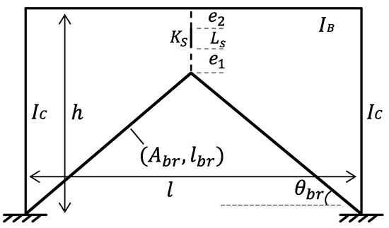
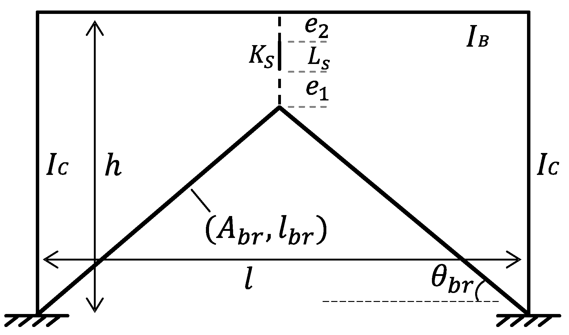
Figure 1 is the schematic diagram of the theoretical model of an eccentrically braced composite frame with a vertical coupling beam. The theoretical model is developed under the following assumptions: (1) The beam–column joints and brace connections are rigid; (2) The vertical link is modeled as a shear-dominant element, neglecting its flexural deformation, which is valid for short links (e < 1.6Mp/Vp); (3) The concrete slab contributes to the beam stiffness via an effective width, assuming full shear connection. Although neglecting the link’s bending flexibility slightly overestimates the initial stiffness, the error is negligible for the global response of shear-critical EBFs, making the model applicable for design purposes; and (4) Slab Interaction: The composite effect is considered using the effective width method. The degradation of composite action due to concrete cracking is explicitly accounted for by switching from the elastic moment of inertia (IB) to the cracked moment of inertia after the cracking point. Both the frame beam and the frame column are beam elements. The position of the beam unit coincides with the centroid and axis of the frame beam and the frame column. The spacing between the frame columns is l, and the height of the frame beam is h. The influence of the node region is not considered in the theoretical model, and the frame beam and the frame column are completely rigid connections. According to the experimental design results, the fully fixed boundary conditions are adopted at the bottom of the column. In the model, IB and IC represent the section moment of inertia of the frame beam section and the frame column section, respectively. The moment of inertia IB of the frame beam section is the moment of inertia of the combined section after considering the complete combination of concrete and steel beam. For the eccentric support part, the coupling beam is mainly subjected to shear in the process of stress, so the shear-only beam element is used to simulate it, and the length is marked as Ls, and the shear stiffness is marked as KS. The diagonal brace is a support component, which is mainly an axial force, so the truss element is used to simulate, and the effective length is marked as lbr, the cross-sectional area is marked as Abr, and the intersection angle between the diagonal brace and the horizontal plane is marked as θbr. The two ends of the coupling beam are rigidly connected with the frame beam and the connecting beam, respectively. There is a certain eccentric distance between the rigid joint and the intersection of the diagonal brace (e1) and between the rigid joint and the center of the frame beam (e2). The linear stiffness ratio of the beam to the column is αC.
Figure 1.
Theoretical model of eccentrically braced composite frame. Theoretical model of structural mechanics adapted from [27].
For the eccentric support part, although the coupling beam undergoes bending deformation, it yields primarily in shear. Therefore, a shear-only beam element is adopted to simulate its behavior in the theoretical model, neglecting the secondary bending moments within the link itself for the global analysis.
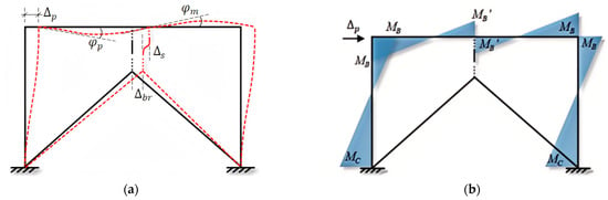
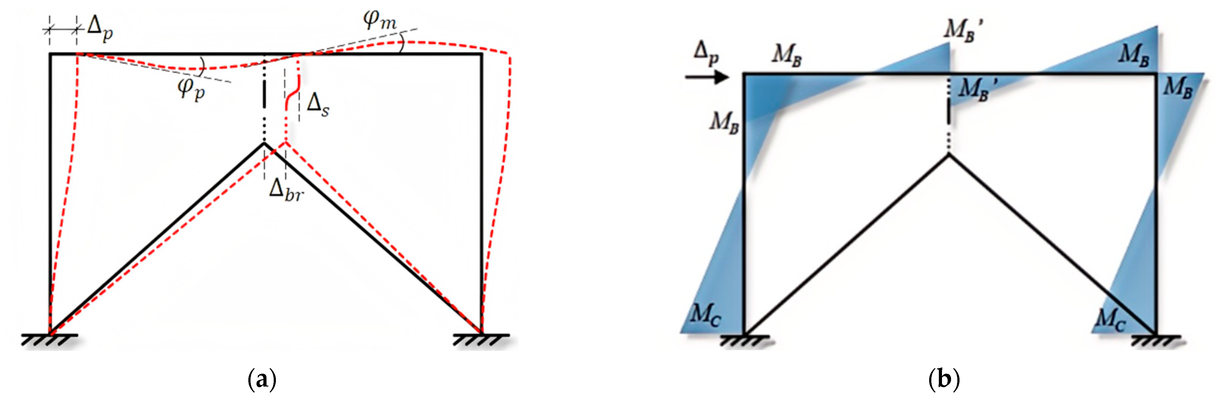
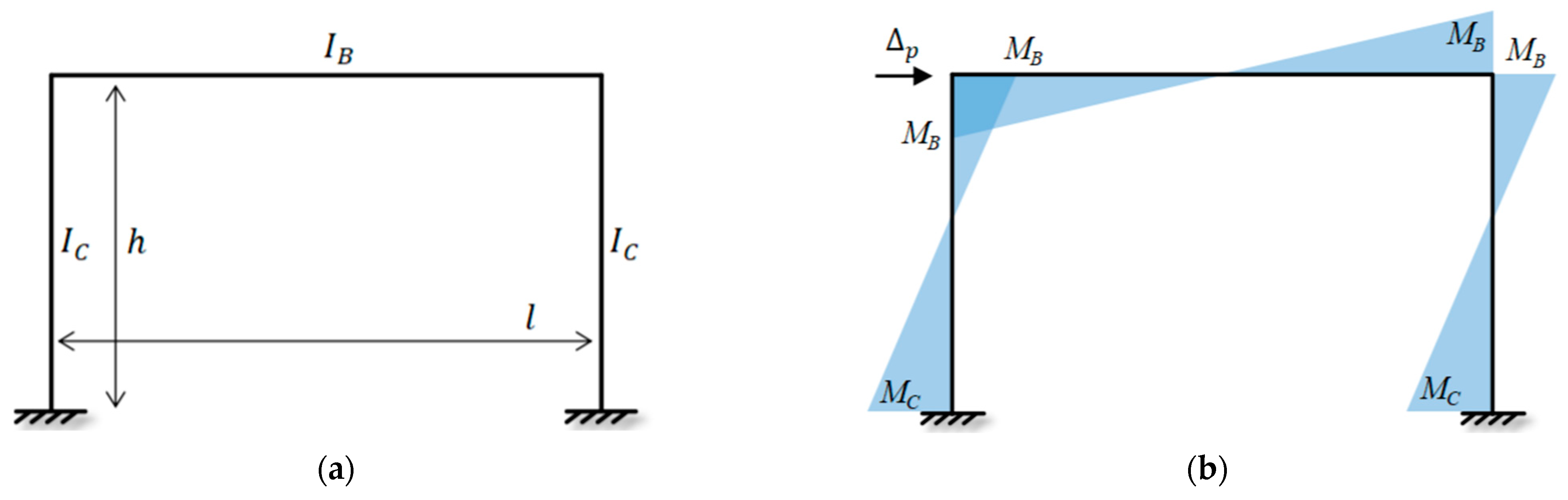
Figure 2 shows the internal force distribution and deformation mode of an eccentrically braced composite frame structure with a vertical coupling beam. According to the internal force distribution diagram, the frame beam and the frame column are mainly bent. The maximum bending moment of the frame column is distributed at both ends of the member. The bending moment of the column base is recorded as MC, and the bending moment at the top of the column is the same as that at the beam end; both are recorded as MB. However, due to the introduction of eccentric support, the bending moment of the frame beam not only reaches a peak at the beam end, but also registers a peak caused by the sudden change in the bending moment at the connection of the vertical coupling beam in the middle of the span, which is recorded as MB’, which is mainly caused by the shear deformation of the vertical coupling beam caused by the lateral displacement of the frame, and the shear reaction of the vertical coupling beam due to the shear deformation in the middle of the frame beam. According to the deformation mode diagram, after the horizontal lateral displacement, Δp, the rotation angle is marked as the lateral deformation of Δs and Δbr at the intersection of the vertical coupling beam and the diagonal brace, and the sum of the two is equal to Δp. In addition, the corners at the end of the frame beam and the middle of the span are respectively recorded as φp and φm.
Figure 2.
Analysis results of eccentrically braced composite frame with vertical shear link: (a) Deformation pattern; (b) Moment diagram. Analysis results adapted from [27].
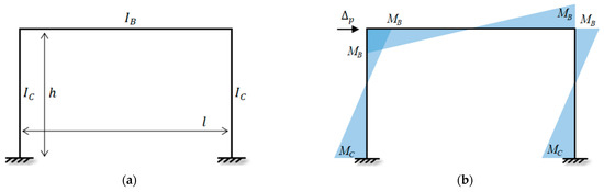
Firstly, the displacement method of structural mechanics is used to analyze the structure without lateral support. MB0, MC0, φp0, and φm0 are, respectively, the bending moment at the beam end, the bending moment at the column bottom, the rotation angle at the beam end, and the rotation angle at the middle of the beam span under the action of the lateral displacement Δp of the composite frame structure without eccentrically braced members, as shown in Figure 3. According to the displacement method, the expressions of MB0 and MC0 can be obtained as shown in Formulas (1)–(3).
Figure 3.
Analysis model of the unbraced composite frame: (a) structural diagram; (b) moment diagram.
By solving the simultaneous equilibrium equations, the governing expressions for the rotation angles and internal moments can be derived explicitly as follows: he detailed step-by-step derivation, including the establishment of slope-deflection equations and equilibrium conditions, is provided in Appendix A.
Consequently, the lateral stiffness for a single column (Kl) and the unbraced composite frame (KF0) are obtained as:
For the eccentrically braced frame structure, it is equivalent to adding a spring with a stiffness of Keq at the distance of e2 + L/2 from the composite frame beam, which is applied M0 = KeqΔp(e2 + Ls/2) in the middle of the span, as shown in Figure 1. Because the structure is symmetrical, half of the structure is selected for analysis, and the rotation angle at the beam–column node is φp1, and the rotation angle at the midspan is φm1. Equations (10) and (11) can be obtained from the displacement method. The resulting expressions are shown in Formulas (12)–(15).
Combined with the calculation results of the non-eccentrically braced frame, the internal force, deformation, lateral stiffness, and lateral load of the key parts of the structure can be obtained as shown in Formulas (16)–(19). Keq is the lateral stiffness of eccentrically braced members, and the calculation method is shown in Formula (21). Therefore, the lateral stiffness KF of eccentrically braced frames is shown in Equation (20), and the calculation formula of lateral thrust is shown in Equation (22).
where E is the elastic modulus of the material, and KS is the shear stiffness of the coupling beam, which is determined by the design parameters of the coupling beam. Kbr is the horizontal stiffness of diagonal bracing members, which can be calculated according to Formula (23) according to the layout of diagonal bracing. α is the linear stiffness ratio of columns, which is a design parameter reflecting the relative stiffness of beam members and column members in the frame structure. It is mainly used to adjust the distribution of internal forces between beams and columns in the frame structure to achieve the design result of “strong columns and weak beams”. Its calculation method is shown in Formula (24).
It can be seen from the above formula that, compared with the original structure, the internal forces at the beam end and column end of the structure are increased after the introduction of eccentric support, while the deformation at the beam end angle and mid-span angle of the original structure are reduced to a certain extent. In addition, the amplitude of the increase in internal forces and the decrease in angular deformation are positively correlated with the lateral stiffness of the eccentric support, the lateral deformation of the structure, and the center distance between the coupling beam and the frame beam. In addition. Compared with the original structure, the lateral stiffness of the structure after the introduction of eccentric support not only increases the lateral stiffness Keq of eccentric support, but also increases an additional stiffness. Equation (21) demonstrates that the lateral stiffness of the structure is derived from the superposition of the unbraced composite frame stiffness (KF0) and the effective stiffness of the eccentric bracing system (Keq). The bracing system stiffness Keq is determined by the series combination of the shear link stiffness (KS) and the diagonal brace stiffness (Kbr), as shown in Equation (20). This mechanism ensures that the bracing system effectively supplements the lateral stiffness of the composite frame. This suggests that the introduction of eccentric support has a “1 + 1 > 2” effect on the improvement of structural stiffness.
3. Theoretical Skeleton Curve
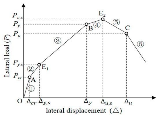
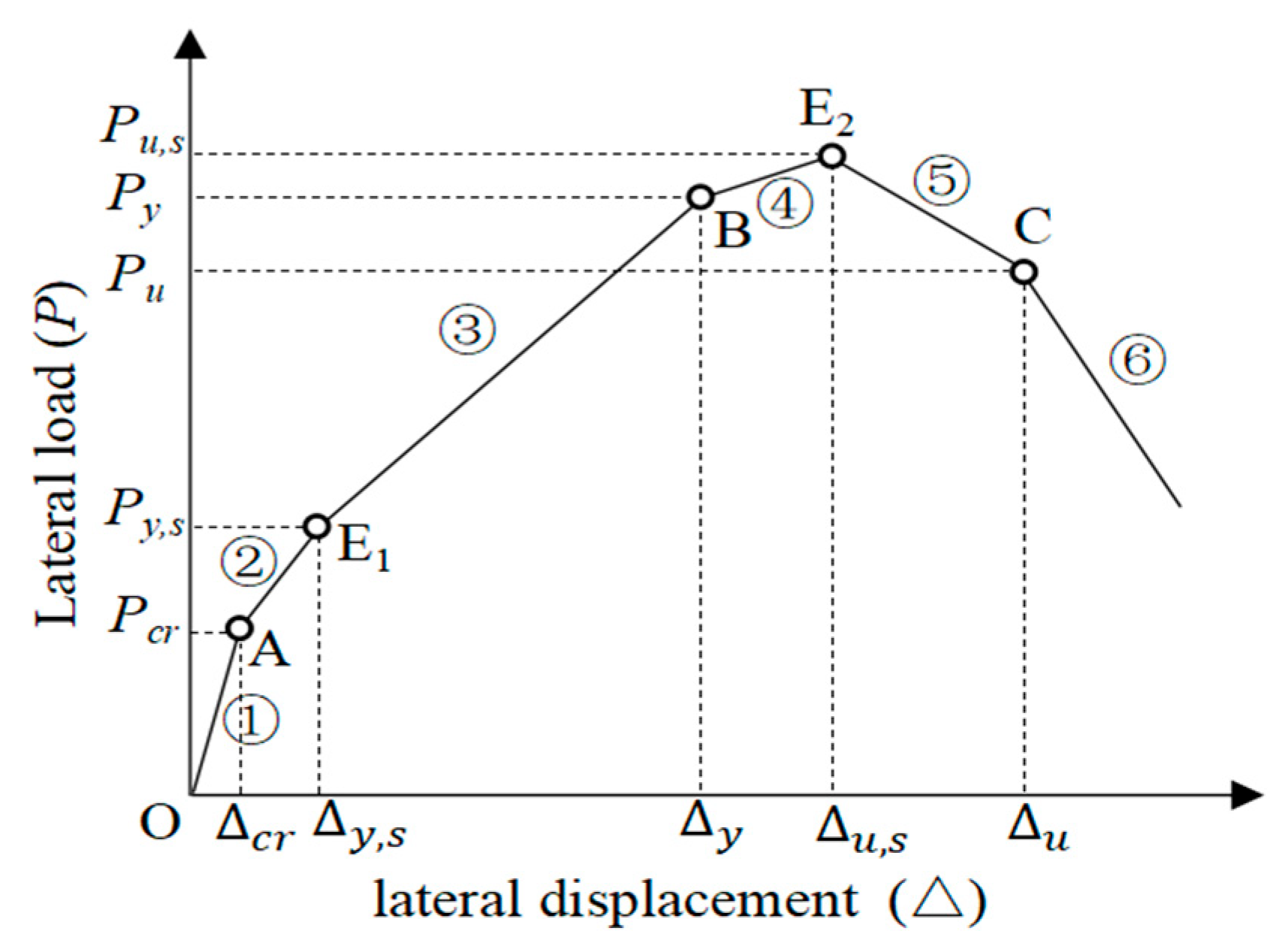
For the composite frame structure with eccentric support, according to the test phenomenon and the characteristics of the test skeleton curve, the development process of the theoretical skeleton curve can be divided into six stages. To facilitate the derivation, the key characteristic points on the skeleton curve are defined as follows: Pcrack and Δcrack denote the load and displacement at the cracking point of the concrete slab; Pys and Δys correspond to the yield point of the vertical shear link; Py and Δy represent the yield point of the composite frame beam; Pus and Δus denote the ultimate capacity point where the link fails; and Pu and Δu represent the final failure point of the global structure. As shown in Figure 4, point A is the cracking point of the concrete slab, and the tensile stress at the edge of the concrete slab at the corresponding beam end reaches the cracking stress of the concrete material. The structure is completely elastic before point A; E1 is the yield point of the vertical coupling beam. Between point A and E1, the structure is basically in an elastic state, but the cracking stiffness of the concrete slab at the beam end may be slightly reduced. Point B is the yield point of the frame beam, and the flange stress of the steel beam corresponding to the beam end section reaches the steel yield stress. From point E1 to point B, the stiffness of the structure shows a downward trend due to the aggravation of the cracking of the concrete slab and the yielding of the coupling beam. However, due to the obvious yield strengthening of the coupling beam and the constraint of the reinforcement on the crack development after the cracking of the concrete slab, the stiffness of the structure at this stage does not decline very fast. E2 point is the failure point of the coupling beam, and the corresponding vertical coupling beam reaches the peak bearing capacity. At this time, the reinforcement of the coupling beam has been completed, the flange or web has buckled or torn obviously, and it will lose its load-bearing capacity. Between point B and point E2, the lateral stiffness of the structure has decreased rapidly due to the yield of the frame beam section. Point C is the failure point of the structure. The corresponding composite frame structure has reached the peak bearing capacity. The steel beam has been torn or buckled by weight, and the bottom end of the frame column has yielded or buckled. Between point E2 and point C, due to the failure of the coupling beam and the intensification of the buckling or tearing of the steel beam, the bearing capacity decreases rapidly. For the ultimate limit state (Point C), the ultimate story drift angle θu is determined based on the seismic design code for composite structures (JGJ 138-2016) [28]. While the physical fracture drift may vary, the code-recommended limit of 1/50 is adopted as the standard design failure criterion to ensure a sufficient safety margin in performance-based design applications.
Figure 4.
Theoretical skeleton curve of an eccentrically braced composite frame with a vertical shear link.
The calculation formula of displacement and load value corresponding to each key point in the theoretical skeleton curve is derived as follows:
(1) When the skeleton curve reaches point A, the stress at the upper edge of the concrete of the composite section at the beam end reaches the crack ft of the material. According to the relationship between the section stress and the internal force, there are
where hB1 is the distance between the centroid of the section and the upper edge of the frame beam.
Combining Equations (16) and (25), the lateral deformation Δcrack at this time can be obtained as Equation (26).
The lateral load Pcrack at this time can be calculated according to Formula (22), as shown in Formula (27).
(2) When the skeleton curve reaches the E1 point, the vertical coupling beam reaches the yield load Vp. Since the lateral deformation Δy,s of the structure is always equal to the lateral deformation of the eccentric support, the magnitude of the lateral deformation at this time can be obtained as shown in Formula (28).
According to the method of calculating the lateral load at point A, the lateral load Py,s of the structure at this time can be calculated, as shown in Formula (29).
(3) When the skeleton curve reaches point B, the end of the frame beam yields; that is, the stress at the lower edge of the steel beam of the composite section of the frame beam reaches the material yield stress fy, as shown in Equation (30).
It should be noted that since the concrete of the frame beam has cracked obviously at this time, the moment of inertia of the frame beam section in Equation (31) should be the moment of inertia IB,cr of the cracked composite section, while hB2,cr are the distance between the middle and axis of the section and the lower edge of the steel beam when the cracked composite section bears a negative moment. Through simultaneous (16) and (30), the lateral displacement Δy of the frame structure at this time can be solved as Equation (31).
where αcr is the linear stiffness ratio of beam to column after cracking of the composite beam section of the frame, and Keq,y is the lateral stiffness of the eccentric support after yielding of the coupling beam.
According to Equation (22), the lateral load Py of the structure at this time can be calculated in Equation (32).
where KF0,cr is the lateral stiffness of the frame structure after cracking of the frame composite beam.
(4) When the skeleton curve reaches the E2 point, the coupling beam reaches the ultimate bearing capacity Vu, and the deformation of the corresponding coupling beam is Δsu. According to the deformation coordination relationship of the structure, the lateral deformation of the structure is equal to the sum of the deformation of the coupling beam and the deformation of the diagonal brace, so the lateral deformation Δu,s of the structure at this time can be obtained as Formula (33).
According to Formula (22), the lateral load Pu,s of the structure at this time can be calculated, as shown in Formula (34).
(5) When the skeleton curve reaches point C, the coupling beam has failed, leaving only a certain residual bearing capacity Vsr. According to the test phenomenon, at this time, the beam end of the frame beam and the bottom end of the frame column have completely yielded, indicating that both the beam end and the column end have reached the maximum plastic bending capacity. According to the internal force balance relationship, the lateral force of the structure at this time can be obtained as shown in Formula (35).
where MB+ and MB− are the maximum plastic positive and negative bending capacity of composite beams, respectively, and Mcy is the maximum plastic bending capacity of the frame column section, which can be referred to “Code for Design of Composite Structures” (JGJ138-2016) [28].
The lateral deformation Δu of the structure at this time is mainly related to the maximum story deformation capacity of the composite frame structure system. For the general composite frame structure, according to the previous experimental research results [29,30,31], when the composite frame reaches the peak bearing capacity, the story displacement angle [θu] is generally between 1/40 and 1/60. Here, it is recommended to take 1/50, which is consistent with the elastic-plastic story displacement angle limit of the composite frame structure recommended by the code. According to the geometric relationship between lateral deformation and inter-story displacement angle, the lateral deformation of the structure at this time can be obtained as Formula (36).
It is imperative to differentiate the physical origins of the key characteristic points within the proposed skeleton curve model to define its theoretical rigor and applicability. While the yield point of the link (E1), the yield point of the frame (B), and the ultimate capacity (E2) are rigorously derived from structural mechanics and plastic equilibrium equations, other parameters incorporate design-oriented simplifications. Specifically, the cracking point (A) assumes an instantaneous transition to the cracked moment of inertia (IB,cr), neglecting the tension stiffening effect of reinforcement, which typically results in a more gradual stiffness degradation in practice; this assumption consequently provides a conservative estimate for design purposes. Furthermore, the ultimate deformation state (C) is defined based on the code-recommended inter-story drift limit (1/50) to align with performance-based safety criteria, rather than a material-level fracture criterion, and the post-peak segment represents a phenomenological idealization of strength degradation due to local buckling.
4. Theoretical Model Verification
This section will compare the test design parameters and test results [21] with the prediction results of the theoretical model to verify the accuracy of the theoretical model. Since the theoretical model is mainly based on the basic theory of structural mechanics, the existing problems of the model will also be discussed and corrected in combination with the test results. According to the experimental design, the design parameters required for theoretical model calculation can be sorted out, and the statistics are shown in Table 1. According to the design parameters of the theoretical model, the intermediate process parameters required for the calculation of internal force and deformation of the structure can be calculated. According to the formula given in the previous section, the calculation results of intermediate process parameters are shown in Table 2.
Table 1.
Design parameters of the theoretical model *.
Table 2.
Intermediate process parameters of the theoretical model *.
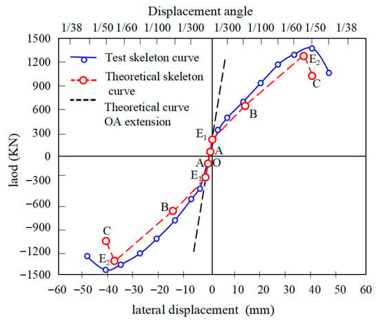
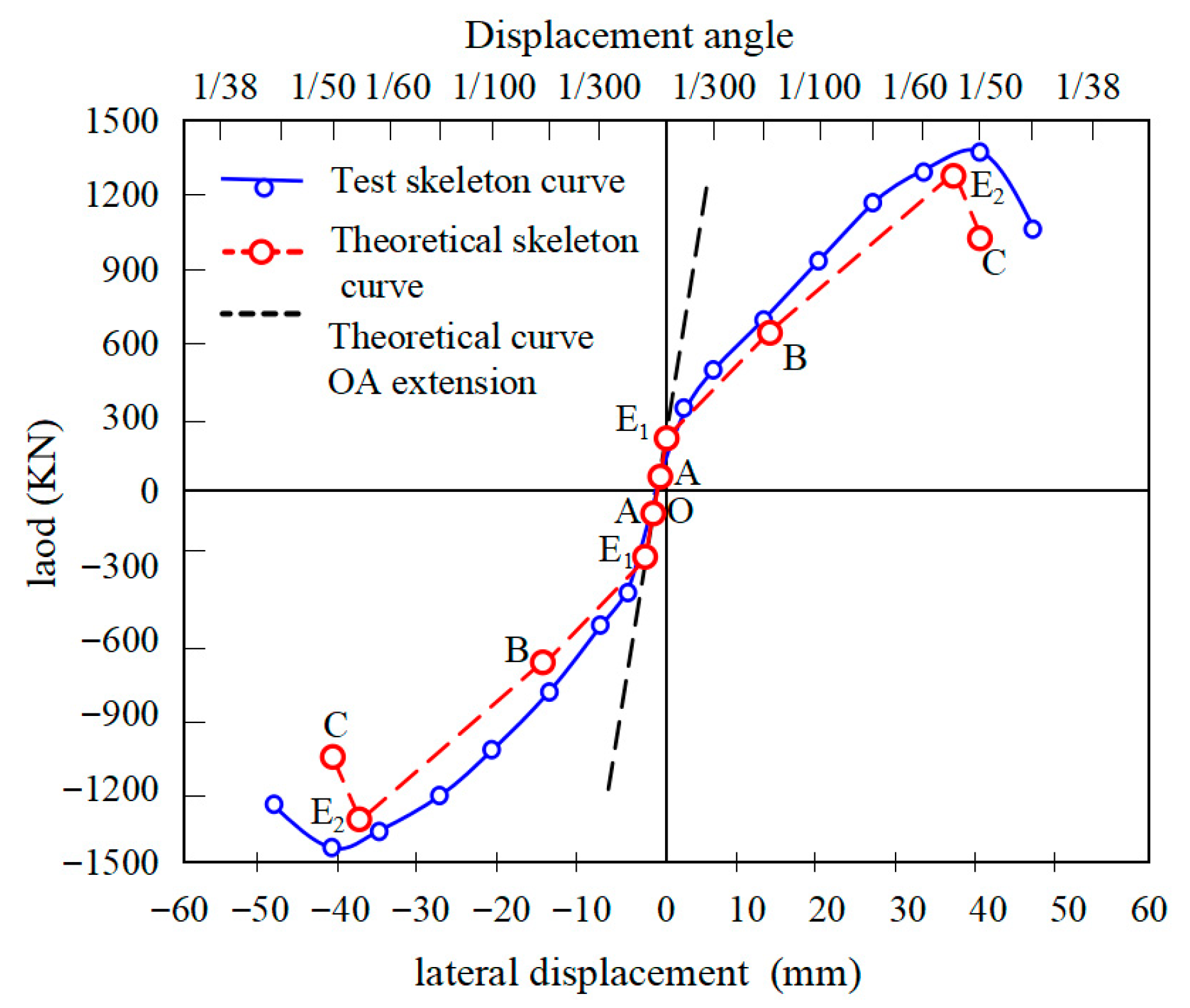
Figure 5 presents the comparison between the theoretical skeleton curve and the experimental envelope curve. The theoretical model divides the mechanical behavior into distinct stages, which align well with the experimental observations.
Figure 5.
Comparison between experimental and theoretical results of Specimen 1.
Quantitatively, the predicted initial stiffness (Ktheo) matches the experimental initial stiffness (Kexp) with a relative error of less than 5%. The predicted yield load (Py) and ultimate load (Pu) show deviations of approximately 6.5% and 8.2%, respectively.
It is worth noting that the theoretical curve is slightly conservative compared to the experimental results in the plastic hardening stage (Segment B–E2). This discrepancy arises because the theoretical model assumes an elastic-perfectly plastic behavior for the shear link material properties to simplify the derivation, whereas the actual steel material exhibits strain hardening. However, for design purposes, this conservative prediction provides a safety margin, confirming that the proposed equations (Equations (16)–(36)) are reliable for predicting the seismic capacity of such structures.
Note that while the unbraced Specimen A provided the baseline stiffness data for Equation (9), the validation in Figure 5 focuses on Specimen B to demonstrate the accuracy of the proposed model for the eccentrically braced system.
5. Quantitative Parametric Study and Design Recommendations
To address the limitations of validating the theoretical model against a single experimental specimen and to demonstrate the model’s generality, a comprehensive quantitative parametric study was conducted. This section investigates the sensitivity of the EBCF’s seismic performance to three critical design variables: the vertical shear link length (LS), the brace-to-link stiffness ratio (β), and the beam-to-column stiffness ratio (α). The analysis utilizes the derived theoretical equations (Equations (6), (7), (20) and (21)) and uses Specimen B (Table 1 parameters) as the baseline configuration.
5.1. Influence of Vertical Shear Link Length on Stiffness
The length of the vertical shear link (LS) governs the shear stiffness (KS) of the link, which follows the relationship KS = GAS/LS, implying KS ∝ 1/LS. According to Equation (21), the equivalent stiffness of the bracing system (Keq) is determined by the series combination of the link and the diagonal brace.
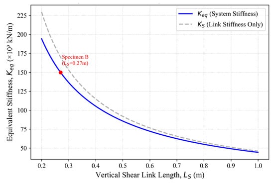
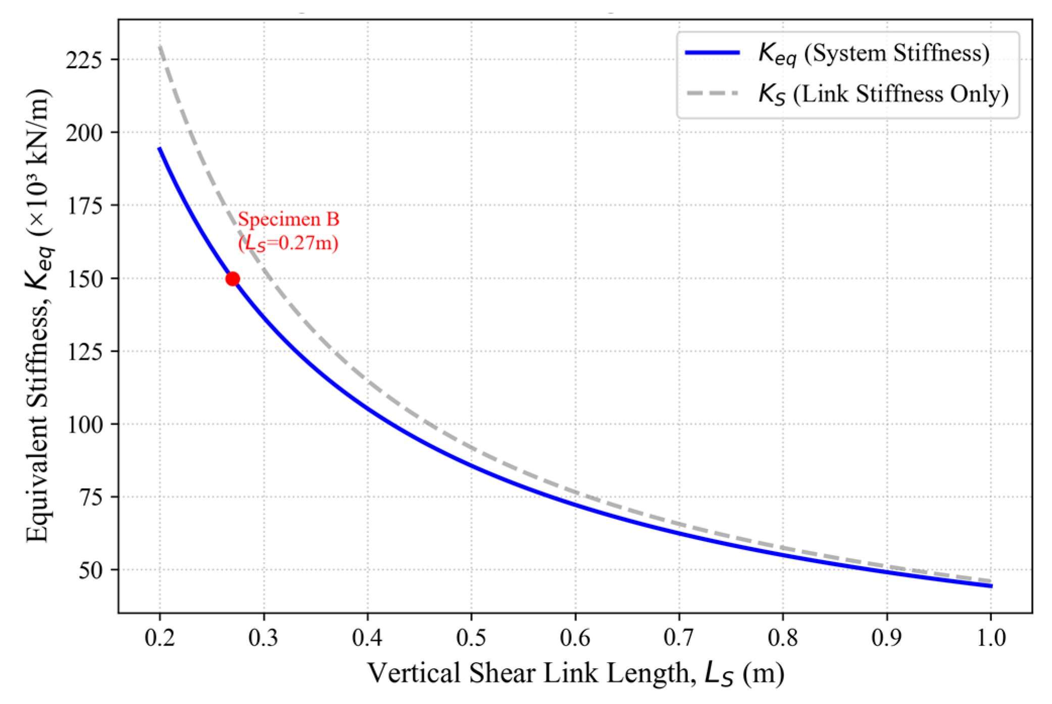
Figure 6 illustrates the theoretical degradation of lateral stiffness as the link length increases from 0.2 m to 1.0 m while keeping the brace stiffness constant at Kbr = 1.26 × 10⁶ kN/m.
Figure 6.
Effect of link length on lateral stiffness.
As shown in Figure 6, the stiffness exhibits a hyperbolic decay. Quantitatively, increasing the link length from the experimental baseline of 0.27 m to 0.60 m results in a 52.4% reduction in the bracing system’s effective stiffness (Keq). While shorter links provide higher stiffness, they impose larger rotation demands (γp) for a given inter-story drift. Based on this parametric sensitivity, a link length ratio of LS/L ≈ 0.10~0.15 is recommended to balance the trade-off between maximizing global stiffness and maintaining ductility limits.
5.2. Brace Stiffness Threshold
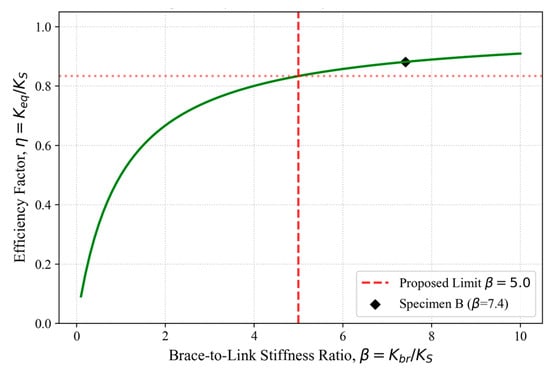
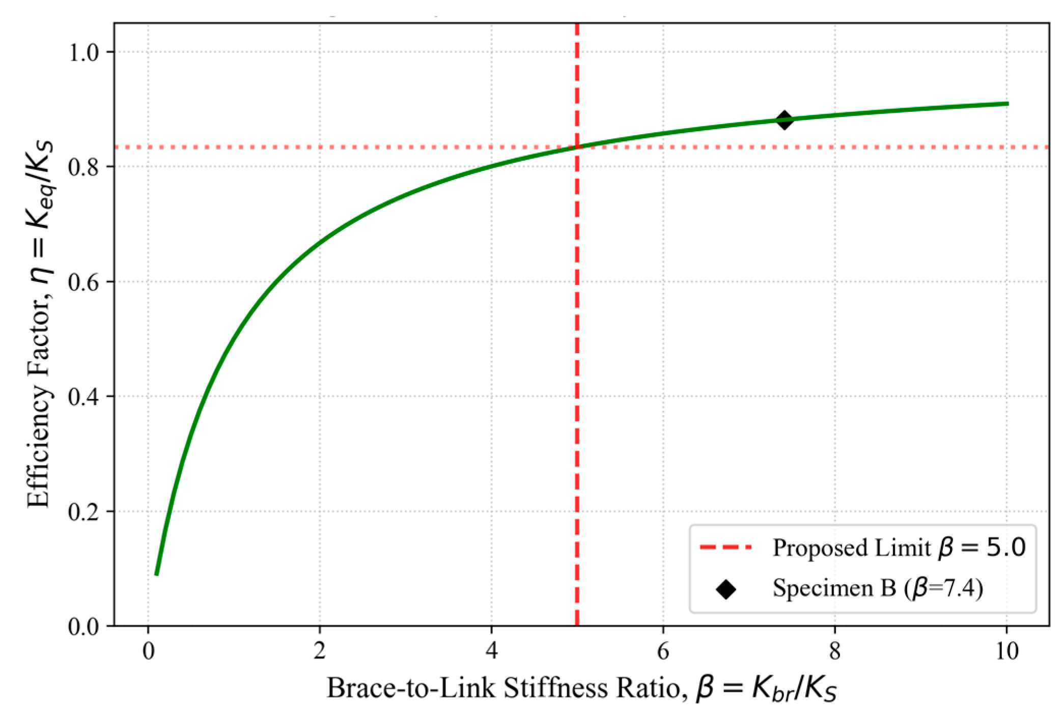
The efficiency of the EBCF system relies on the “Strong Brace, Weak Link” mechanism. If the brace is too flexible, the system stiffness is dominated by the brace rather than the energy-dissipating link. We define the stiffness ratio β = Kbr/KS and the system efficiency factor η = Keq/KS. Substituting into Equation (21) yields η = β/(1 + β). Figure 7 plots this efficiency curve.
Figure 7.
System efficiency with stiffness ratio.
The results in Figure 7 indicate that the efficiency curve plateaus significantly when β > 5.0. For Specimen B, the ratio was β ≈ 7.4, corresponding to an efficiency of η = 0.88. Conversely, if β < 3.0, the efficiency drops below 0.75, indicating that brace deformation constitutes a significant portion of the total drift. Therefore, a design threshold of Kbr ≥ 5KS is proposed to ensure the brace remains effectively rigid relative to the link.
5.3. Effect of Beam-to-Column Stiffness Ratio
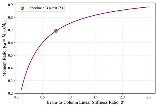
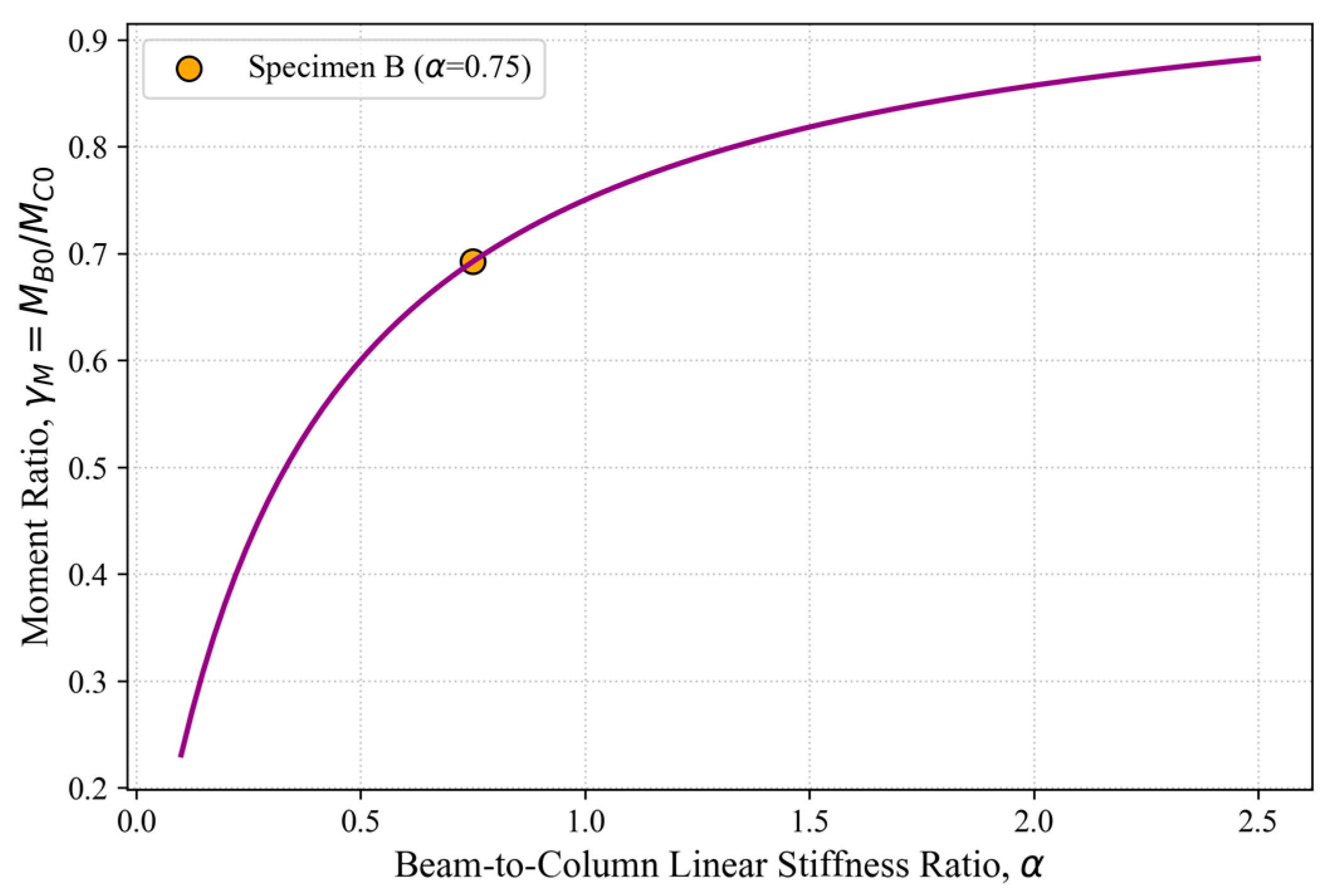
The linear stiffness ratio α (defined in Equation (24)) controls the internal force distribution. Using Equations (6) and (7), we analyzed the ratio of beam-end moment to column-base moment (γM = MB0/MC0) under elastic unbraced conditions. Figure 8 presents the variation in moment distribution as α increases from 0.1 to 2.5.
Figure 8.
Effect of stiffness ratio on moment distribution.
The analysis demonstrates that as α increases (indicating stiffer composite beams due to slab contribution), the moment demand shifts towards the beam ends. Specifically, increasing α from 0.5 to 1.5 increases the moment ratio γM by approximately 45%. This quantitative finding highlights that in composite frames, where α is typically higher than in bare steel frames, beam–column connections must be strengthened to accommodate higher moment demands derived from the composite action.
6. Conclusions
In this paper, based on the test results, the mechanical properties of eccentrically braced composite frames with vertical coupling beams are studied by means of theoretical analysis. The theoretical model of the structure is established, and the theoretical skeleton curve of the structure is given. From a performance-based design perspective, the theoretical results suggest that the brace stiffness Kbr should be at least 5 times the link stiffness to ensure the link yields prior to brace buckling. Furthermore, the system exhibits a theoretical ductility factor u = Δu/Δy ranging from 3.0 to 5.0, confirming its suitability for high-seismicity regions. Finally, the influence of key design parameters on the mechanical properties of the structure is discussed:
(1) According to the theoretical model established in this paper, the internal force distribution and deformation mode of the structure under different lateral loads can be calculated. In addition, the results of theoretical model analysis show that after the introduction of eccentrically braced members, the internal forces of the beam end and column end of the original composite frame increase, the internal forces of the frame beam in the middle of the span increase, the damage of the concrete slab increases, and the lateral stiffness of the structure increases significantly, which is completely consistent with the conclusions obtained from the analysis of experimental results, further verifying the accuracy of the theoretical model.
(2) According to the development characteristics of the load displacement skeleton curve of the structure, the theoretical skeleton curve model of “polyline” type is given in this study. According to the characteristics of the structure in different stress stages, the skeleton curve is divided into six stages. Combined with the calculation formula of the theoretical model, the calculation method of the displacement and bearing capacity of the key points of the theoretical skeleton curve is derived. The theoretical skeleton curve obtained by this method is in good agreement with the experimental skeleton curve.
(3) Based on the theoretical parametric analysis, the shear link length (Ls) and brace stiffness (Kbr) are identified as the governing parameters. The analytical derivation indicates that minimizing Ls maximizes global stiffness but imposes higher rotational demands. To achieve the intended ‘shear yield’ mechanism, the theoretical model establishes a minimum stiffness requirement for the bracing members to prevent premature global deformation.
(4) It is important to acknowledge the limitations of the current study. The theoretical formulations and parametric sensitivity analyses presented herein are validated against a single experimental specimen. Consequently, the accuracy and broader applicability of the proposed model should be interpreted with appropriate caution. Future research efforts should focus on conducting extensive experimental campaigns and comprehensive numerical simulations to further verify the reliability of the proposed design method across a wider range of geometric configurations and material properties.
Author Contributions
Writing—original draft preparation, Y.-K.H.; methodology, L.-D.Z.; conceptualization, L.-D.Z.; methodology, H.-Y.W.; writing—review and editing, H.-Y.W.; formal analysis, Y.L.; resources, L.-L.F.; visualization, L.-L.F. All authors have read and agreed to the published version of the manuscript.
Funding
This research was funded by the Chongqing Science and Technology Bureau, grant number CSTB2025NSCQ-GPX0773; the China Postdoctoral Science Foundation, grant number 2024M763871; and the Fundamental Research Funds for the Central Universities, grant number 2025CDJZKKYJH-05.
Institutional Review Board Statement
Not applicable.
Informed Consent Statement
Not applicable.
Data Availability Statement
The data generated in this study can be obtained from the corresponding author upon reasonable request.
Acknowledgments
The authors gratefully acknowledge the technical support from Nanjing Forestry University, Chongqing University, and CSSC Haizhuang Windpower Co., Ltd. At the same time, the authors are grateful to the anonymous reviewers and editors for their input and constructive comments.
Conflicts of Interest
Author Lilong Fan was employed by the China Railway Construction Bridge Engineering Bureau Group Co., Ltd. The remaining authors declare that the research was conducted in the absence of any commercial or financial relationships that could be construed as a potential conflict of interest.
Abbreviations
The following abbreviations are used in this manuscript:
| Symbol | Definition | Unit |
| Elastic modulus of the material | N/mm2 | |
| Moment of inertia of the composite frame beam (elastic) | m4 | |
| Cracked moment of inertia of the composite frame beam | m4 | |
| Moment of inertia of the frame column | m4 | |
| Story height of the frame | m | |
| Span length of the frame | m | |
| Length of the vertical shear link | m | |
| Shear stiffness of the vertical shear link | kN/m | |
| Horizontal stiffness of the diagonal brace | kN/m | |
| Equivalent lateral stiffness of the eccentric bracing system | kN/m | |
| Total lateral stiffness of the eccentrically braced frame | kN/m | |
| Linear stiffness ratio of beam to column | - | |
| Eccentricity from brace intersection to link-beam joint | m | |
| Eccentricity from the beam center to the link-beam joint | m | |
| Lateral load acting on the frame | kN | |
| Lateral displacement of the frame | m | |
| Bending moment at the beam end | kN·m | |
| Bending moment at the column base | kN·m | |
| Rotation angle at the beam–column joint | rad | |
| Rotation angle at the beam mid-span | rad | |
| Lateral load at the concrete cracking point (Point A) | kN | |
| Lateral load at the shear link yield point (Point E1) | kN | |
| Lateral load at the frame yield point (Point B) | kN | |
| Ultimate lateral bearing capacity (Point C) | kN |
Appendix A. Detailed Derivation of Lateral Stiffness
This appendix details the derivation of the lateral stiffness for the composite frame, based on the Displacement Method (Slope-Deflection Method).
Appendix A.1. Basic Stiffness Parameters
First, the linear stiffness of the frame column (ic) and the composite beam (ib) are defined as: ic = EIc/h, ib = EIb/h. The beam-to-column linear stiffness ratio α is defined as: α = ib/ic.
Appendix A.2. Slope-Deflection Equations
Assuming the column bottom is fully fixed, the rotation at the bottom is zero. Under a lateral inter-story displacement Δ, the chord rotation angle of the column is ψ = Δ/h. According to the slope-deflection method, the moments at the top (Mct) and bottom (Mcb) of a single column are shown in Equations (A1) and (A2).
where φp is the rotation angle at the beam–column joint.
For the composite beam, due to symmetry under lateral loading, the mid-span is an inflection point (moment is zero). The moment at the beam end (Mb) can be expressed as: Mb = 6ib/φp.
Appendix A.3. Equilibrium Equation
Consider the moment equilibrium at the beam–column joint node (∑M = 0). The sum of the moments from the column top and the beam end must be zero: Mct + Mb = 0. Substituting the slope-deflection expressions into the equilibrium equation yields Equation (A3).
Appendix A.4. Solution for Rotation Angle
Solving the above equation for the joint rotation φp yields Equation (A4).
Appendix A.5. Calculation of Lateral Stiffness (KF0)
The shear force (Vc) in a single column can be obtained from the moment equilibrium of the column element, as shown in Equations (A5) and (A6).
Substituting the expression for φp obtained in Appendix A.4 into the shear equation yields Equation (A7).
Note: Simplification leads to the classic D-value method formula. For the specific frame configuration in this study, assuming infinite rigidity of the beam–column connection region is ignored for derivation simplicity, the total lateral stiffness of the frame (KF0) consisting of two columns is the sum of shear forces divided by displacement: KF0 = ∑Vc/Δ.
This derivation process validates the Formulas presented in Equations (8) and (9) of the main text. For the eccentrically braced system, the equivalent stiffness Keq derived from the series combination of the link and brace is directly superimposed onto KF0.
References
- Zong, Z.H.; Lin, D.; Fang, Z.; Qiu, F. Experimental study on seismic behavior of two-storey concrete-filled steel tube composite frame. J. Build. Struct. 2002, 2, 27–35. [Google Scholar]
- Jiang, L.; Wang, C. Seismic elasto-plastic time history analysis of steel-concrete composite frame structure. Railw. Sci. Eng. 2008, 2, 7–11. [Google Scholar]
- Huang, Y. Experimental Study and Model Analysis on Mechanical Behavior of Steel-Concrete Composite Frame. Ph.D. Dissertation, Tsinghua University, Beijing, China, 2009. [Google Scholar]
- Wang, Y.L.; Zhao, M.; Hao, H.P.; Xue, Q.; Jiang, W.S. Seismic analysis of steel-concrete composite frame structure based on limit equilibrium theory. Eng. Mech. 2022, 39, 81–88. [Google Scholar] [CrossRef] [Scilit]
- Ma, F.D.; Deng, M.K.; Yang, Y. Seismic behavior of monolithic frame beam-column joint assembled with ultra-high performance concrete. Eng. Mech. 2021, 38, 90–102. [Google Scholar]
- Li, T.F.; Sui, M.Z.; Sui, L.; Zhao, K.; Zhang, Q.; Wang, L.L. Mixed experimental study on seismic behavior of high-strength steel Y-shaped eccentrically braced frame. Eng. Mech. 2021, 38, 221–231. [Google Scholar]
- Keivan, A.; Zhang, Y. Nonlinear seismic performance of Y-type self-centering steel eccentrically braced frame buildings. Eng. Struct. 2019, 179, 448–459. [Google Scholar] [CrossRef] [Scilit]
- Malley, J.O.; Popov, E.P. Shear links in eccentrically braced frames. J. Struct. Eng. 1984, 110, 2275–2295. [Google Scholar] [CrossRef] [Scilit]
- Azad, S.K.; Topkaya, C. A review of research on steel eccentrically braced frames. J. Constr. Steel Res. 2017, 128, 53–73. [Google Scholar] [CrossRef] [Scilit]
- Popov, E.P.; Engelhardt, M.D. Seismic eccentrically braced frames. J. Constr. Steel Res. 1988, 10, 321–354. [Google Scholar] [CrossRef] [Scilit]
- Popov, E.P.; Engelhardt, M.D.; Ricles, J.M. Eccentrically braced frames: US practice. Eng. J. 1989, 26, 66–80. [Google Scholar] [CrossRef] [Scilit]
- Roeder, C.W. Inelastic Behavior of Eccentrically Braced Steel Frames Under Cyclic Loading. Ph.D. Dissertation, University of California, Berkeley, CA, USA, 1977. [Google Scholar]
- Manheim, D.N. On the Design of Eccentrically Braced Frames. Ph.D. Dissertation, University of California, Berkeley, CA, USA, 1982. [Google Scholar]
- Kasai, K. A Study of Seismically Resistant Eccentrically Braced Steel Frame System. Ph.D. Dissertation, University of California, Berkeley, CA, USA, 1986. [Google Scholar]
- Sullivan, T.J. Direct displacement-based seismic design of steel eccentrically braced frame structures. Bull. Earthq. Eng. 2013, 11, 2197–2231. [Google Scholar] [CrossRef] [Scilit]
- Montuori, R.; Nastri, E.; Piluso, V. Rigid-plastic analysis and moment–shear interaction for hierarchy criteria of inverted Y EB-Frames. J. Constr. Steel Res. 2014, 95, 71–80. [Google Scholar] [CrossRef] [Scilit]
- Montuori, R.; Nastri, E.; Piluso, V. Theory of plastic mechanism control for eccentrically braced frames with inverted y-scheme. J. Constr. Steel Res. 2014, 92, 122–135. [Google Scholar] [CrossRef] [Scilit]
- Lian, M.; Su, M.Z.; Li, S. Study on Performance-based Plastic Design Method for Y-shaped High Strength Steel Composite Eccentrically Braced Frame Structures. Eng. Mech. 2017, 34, 148–162. [Google Scholar]
- Li, T.F.; Su, M.Z.; Sui, L.; Ma, L.; Han, D. Mixed seismic performance test of K-shaped eccentrically braced high-strength steel frame. Eng. Mech. 2019, 36, 100–108+124. [Google Scholar]
- Ciutina, A.; Dubina, D.; Danku, G. Influence of Steel-Concrete Interaction in Dissipative Zones of Frames: I-Experimental Study. Steel Compos. Struct. 2013, 15, 299–322. [Google Scholar] [CrossRef] [Scilit]
- Danku, G.; Dubina, D.; Ciutina, A. Influence of Steel-Concrete Interaction in Dissipative Zones of Frames: II-Numerical Study. Steel Compos. Struct. 2013, 15, 323–342. [Google Scholar] [CrossRef] [Scilit]
- Prinz, G.; Sousa, A.A. Effect of Slab Stiffness on EBF Link Rotation Demands and Implications for Link Ultra Low-Cycle Fatigue Susceptibility. In Proceedings of the Structures Congress 2014, Boston, MA, USA, 3–5 April 2014; American Society of Civil Engineers: Reston, VA, USA, 2014; pp. 2664–2674. [Google Scholar]
- Chao, S.-H.; Khandelwal, K.; El-Tawil, S. Ductile Web Fracture Initiation in Steel Shear Links. J. Struct. Eng. 2006, 132, 1192–1200. [Google Scholar] [CrossRef] [Scilit]
- Leon, R.T.; Hajjar, J.F.; Gustafson, M.A. Seismic Response of Composite Moment-Resisting Connections. I: Performance. J. Struct. Eng. 1998, 124, 868–876. [Google Scholar]
- Nakashima, M.; Matsumiya, T.; Suita, K.; Zhou, F. Full-Scale Test of Composite Frame under Large Cyclic Loading. J. Struct. Eng. 2007, 133, 297–304. [Google Scholar] [CrossRef] [Scilit]
- Zhuang, L.; Wang, J.; Nie, X.; Wu, Z. Experimental Study on Seismic Behaviour of Eccentrically Braced Composite Frame with Vertical LYP Steel Shear Link. Eng. Struct. 2022, 255, 113957. [Google Scholar] [CrossRef] [Scilit]
- Zhuang, L.-D.; Zhao, J.-Z. Numerical Study on the Seismic Behavior of Eccentrically Braced Composite Frames with a Vertical Low-Yield-Point Steel Shear Link. Buildings 2022, 12, 1359. [Google Scholar] [CrossRef] [Scilit]
- JGJ 138-2016; Code for Design of Composite Structures. China Construction Industry Press: Beijing, China, 2016.
- Tagawa, Y.; Kato, B.; Aoki, H. Behavior of Composite Beams in Steel Frame under Hysteretic Loading. J. Struct. Eng. 1989, 115, 2029–2045. [Google Scholar] [CrossRef] [Scilit]
- Nie, J.; Huang, Y.; Yi, W.; Fan, J. Seismic Behavior of CFRSTC Composite Frames Considering Slab Effects. Steel Constr. 2012, 68, 165–175. [Google Scholar]
- Shi, G.; Yin, H.; Hu, F.X.; Cui, Y. Experimental Study on Seismic Behavior of Full-Scale Fully Prefabricated Steel Frame: Members and Joints. Eng. Struct. 2018, 169, 162–178. [Google Scholar] [CrossRef] [Scilit]

Disclaimer/Publisher’s Note: The statements, opinions and data contained in all publications are solely those of the individual author(s) and contributor(s) and not of MDPI and/or the editor(s). MDPI and/or the editor(s) disclaim responsibility for any injury to people or property resulting from any ideas, methods, instructions or products referred to in the content. |
© 2026 by the authors. Licensee MDPI, Basel, Switzerland. This article is an open access article distributed under the terms and conditions of the Creative Commons Attribution (CC BY) license.