


Abstract
Tunnels are critical components of transportation networks. Explosions caused by accidents or terrorist attacks can severely damage tunnel linings and even cause structural collapse. This paper develops the validated simulation model for single-channel tunnels into a twin-channel tunnel model. Subsequently, a simulation study investigates the damage state and vulnerability of the twin-channel tunnel under single-sided internal blasting. The results suggest that the supporting effect of the soil can improve the blast resistance of the outer wall of the tunnel. An explosion within a single channel can induce changes in the relative bearing capacity of the twin-channel lining. Under the influence of earth pressure, the relative bearing capacity of the twin-channel lining is further weakened, thereby affecting the overall failure state of the tunnel. Longitudinal plastic strain is primarily distributed at the ends and center of walls and floors, and it spreads as the charge mass increases. The charge location has a significant impact on the damage state of the outside walls of the uncharged channel of the tunnel. Placing explosives on tunnel walls will increase the damage level of the twin-channel tunnel. When the charge weight exceeds 1000 kg and 3000 kg, respectively, the exceedance probability for minor damage and severe damage to the tunnel approaches 1. The strengthening of the blast protection level of the center wall is the key to preventing tunnel collapse.
1. Introduction
Tunnels are an important part of the transportation network. Explosive events caused by vehicles carrying hazardous chemicals and terrorist attacks can have a serious impact on tunnel linings [1], and even result in tunnel collapses, which can pose a significant threat to human life and the functionality of the transportation network [2]. Shock wave propagation through the soil is rapidly attenuated when the explosives are ignited outside the tunnel. A single reflection occurs when the external blast shock wave contacts the tunnel lining [3]. However, when the explosives are detonated inside the tunnel, the shock wave will be reflected several times inside the tunnel [4]. Therefore, the destructive action of the internal blast load on the tunnel is greater than that of the external blast load [5,6].
The damage state of the tunnel lining under internal blast loading is influenced by various factors [7], such as charge mass, charge location, tunnel shape, and soil pressure. In addition, a large number of scholars have carried out research on the dynamic response and damage state of tunnels under internal blast loading. Prasanna [8] investigated the effect of lining material, lining thickness, lining shape (circular, rectangular and straight walled arch) and soil type on the dynamic response of a single channel tunnel under internal blast loading by numerical simulation, and the results indicate that circular tunnels are the best in terms of blast resistance. In addition, the stiffness between the soil and the structure has an important influence on the tunnel’s performance against internal blast loading. Increasing the friction coefficient between soil and structure, soil stiffness, and buried depth of the tunnel can reduce the dynamic response of the tunnel under internal blast loading [9]. Liu [10] found that the damage in shield tunnels under internal blast loading is mainly distributed in the joint part of the segment. The joint stiffness of the segment has an important influence on the damage degree of the shield tunnel, and the bolt prestress can improve the blast resistance of the shield tunnel [11]. Xu [12], in an internal blast test in a rectangular twin-channel tunnel, found that damage to the middle wall increases the compression of the lining by earth pressure. In addition, blast loading can disrupt the functionality of fire-retardant coatings inside tunnels. In an analysis of the factors affecting single-channel horseshoe tunnels, Cheng [13] found that increasing the concrete strength grade, concrete thickness, and rock stiffness was more effective than increasing the reinforcement rate in enhancing the resistance of tunnels to deflagration. For the assembled twin-channel tunnel, the middle wall is the weakest part. Increasing the number, thickness, and reinforcement rate of the middle wall can effectively improve the blast resistance of the middle wall [14]. Furthermore, the presence of air vents in tunnels has a significant role in reducing the effect of blast loads on the tunnel lining [15]. Tiwari [16] discovered that the radius of curvature has a significant effect on the deformation and damage of curved tunnels under internal blast loading. Higher deformation and damage exist in tunnels with a smaller radius of curvature. The location of explosives inside the tunnel affects the propagation pattern of the blast shock wave inside the tunnel [17], which affects the damage state of the tunnel lining [13]. Dolatshahi [18] found that pre-cracking of tunnels significantly reduces the blast resistance of tunnels, while pre-cracking of vaults has the greatest impact on the damage to tunnels. Tiwari [19] observed that an increase in charge mass aggravates the level of damage in tunnels. This is due to the fact that a greater charge weight results in a higher explosive energy release upon detonation of the explosive [20]. Liu [21] analyzed the effect of soil-structure action on the damage of tunnels under internal detonation, and came to an important conclusion that the restraining effect of the soil on the structure and the plastic deformation of the soil can weaken the damage of the lining caused by the internal blast loads.
Damage assessment of tunnels under the action of different environments has been taken as an important research project by many scholars, such as fires [22], earthquakes [23], earth excavations [24], and explosions [25]. An explosion is an important component that threatens the safety of tunnels. After the internal blast loads cause damage to the tunnel lining, a series of secondary hazards can be triggered, such as the influx of water and soil from outside the lining. Hence, damage assessment of tunnels under internal blast loading is a significant aspect of blast damage assessment. In particular, the vulnerability of the tunnel is an important part of the damage assessment. Liu [26] plotted the vulnerability of a single-channel semicircular tunnel and found that the tunnel was in mild and moderate damage when the explosive weight was 200 kg; the tunnel collapsed when the explosive weight reached 1000 kg. Bai [27] proposed a method for predicting damage to tunnel linings for various blast threat sizes and tunnel geometries. Zhang [28] analyzed the specific effects of bomb guidance accuracy and TNT weight on tunnel brittleness, and also employed a tunnel blast vulnerability function to quantify the probability of tunnel damage at various levels of damage.
In the above studies, the damage state and damage assessment of single-channel tunnels under implosion loading were mainly investigated. However, there is a lack of research on the damage state and damage assessment of twin-channel tunnels under internal blast loading. Therefore, in this paper, numerical simulation is carried out by LS-DYNA software (Version: R12) to investigate the damage state and vulnerability of a twin-channel tunnel under single-sided internal blast loading. The damage state of a twin-channel tunnel under single-sided internal blast loading was investigated for different combinations of weight and location of the charge. The vulnerability diagram of the twin-channel tunnel was drawn by vulnerability analysis. It can provide a risk assessment basis for the quick judgment of the damage level and damage probability of the twin-channel tunnels under different charge weights.
2. Development and Validation of Numerical Simulation Model
In this section, internal explosion tests and static tests of single-channel tunnels that have been implemented by other scholars are first presented. After that, a numerical simulation model of the tunnel under dynamic load (i.e., internal blast load) and static load (i.e., static bearing capacity) was developed using LS-DYNA software on the basis of the test results. At the same time, the simulation results are compared with the experimental results. Thus, the validity of the numerical simulation model is verified.
2.1. Field Test
This section describes the field tests used to validate the numerical simulation methodology, i.e., the internal blast test and the static bearing capacity test of reinforced concrete tunnels by Liu (the test data are sourced from Ref. [29]).
2.1.1. Dimensions and Composition of the Tunnel
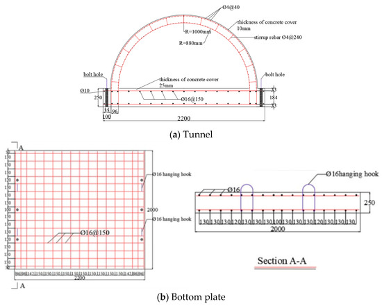
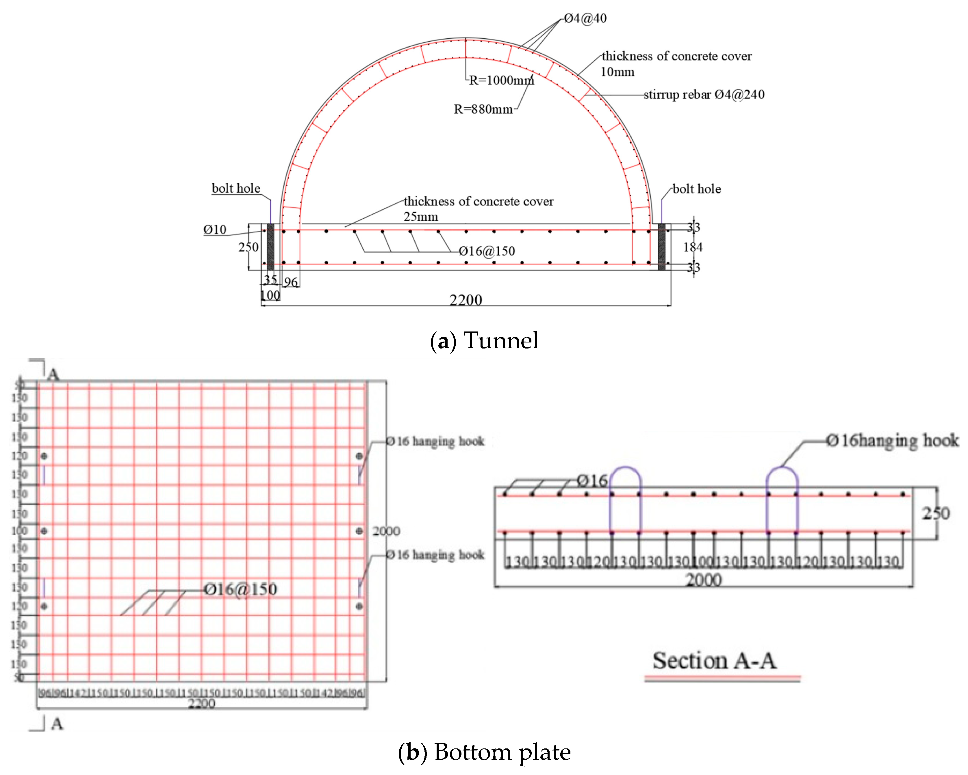
In the tests, the data for the single-channel tunnel structure were obtained from reference [29]. The tunnel consists of reinforced bars and concrete. The longitudinal length of the tunnel is 2000 mm. The tunnel lining has a semi-circular cross-section. The inner and outer radii of the tunnel lining are 880 mm and 1000 mm, respectively. The double layer of reinforcement (6 mm in diameter) inside the arch lining is spaced 85 mm apart both circumferentially and longitudinally. The thickness of the base plate is 250 mm, and it is embedded with reinforcement bars (16 mm in diameter). The yield strength of the reinforcing bar for the arch lining and bottom plate is 450 MPa. The thickness of the protective layer of reinforcement is 10 mm. The compressive strengths of the concrete for the arch lining and bottom plate are 31.35 MPa and 45.65 MPa, respectively. See Figure 1 for tunnel dimensions and reinforcement layout.
Figure 1.
Tunnel dimensions and reinforcement layout (Data from reference [29]).
2.1.2. Internal Blast Test
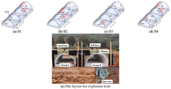
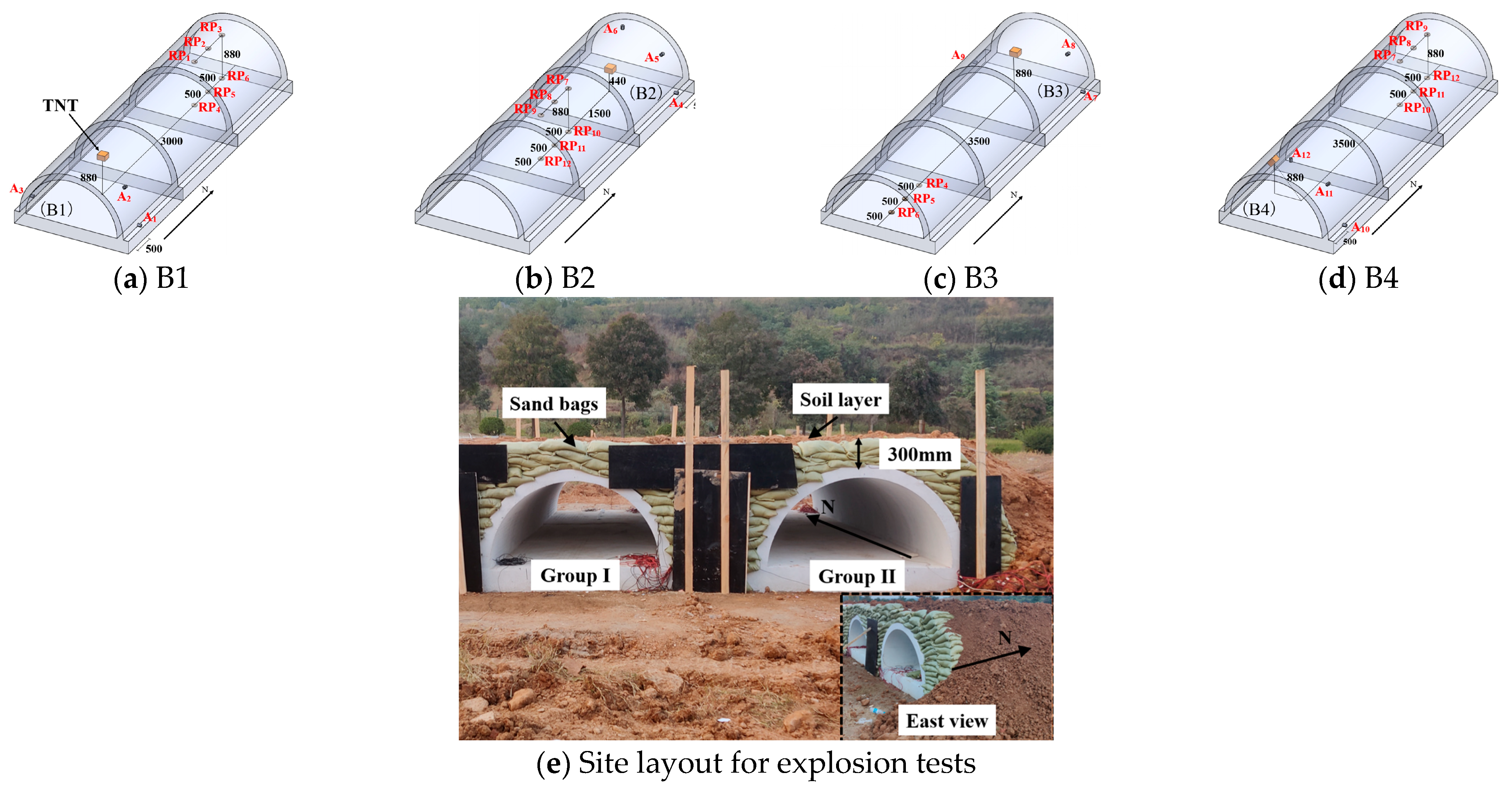
Four internal blast tests were performed on a tunnel buried at a depth of 300 mm. The weight of TNT explosives was 1~2 kg for the four internal blast tests. The explosive consists of multiple 200 g square explosive blocks (length × width × height = 100 mm × 50 mm × 25 mm). The charge locations are set at the top, center, and hance of the tunnel. The specific conditions of the four internal blast tests are described in Table 1. Pressure sensors (i.e., RP1-RP12) are installed inside the tunnel to measure the reflected over-pressure caused by internal explosions. The distribution of pressure sensors and the site layout for the explosion test are shown in Figure 2.
Table 1.
Charge conditions for internal blast tests of tunnels (Data from reference [29]).
Figure 2.
Distribution of pressure sensors (i.e., RP1-RP12) and site layout for explosion tests (Data from reference [29]).
2.1.3. Static Bearing Capacity Test
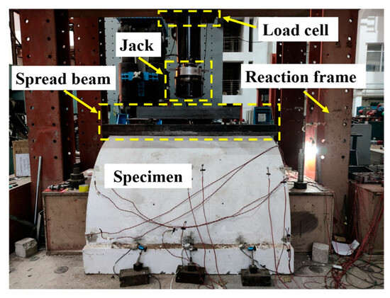
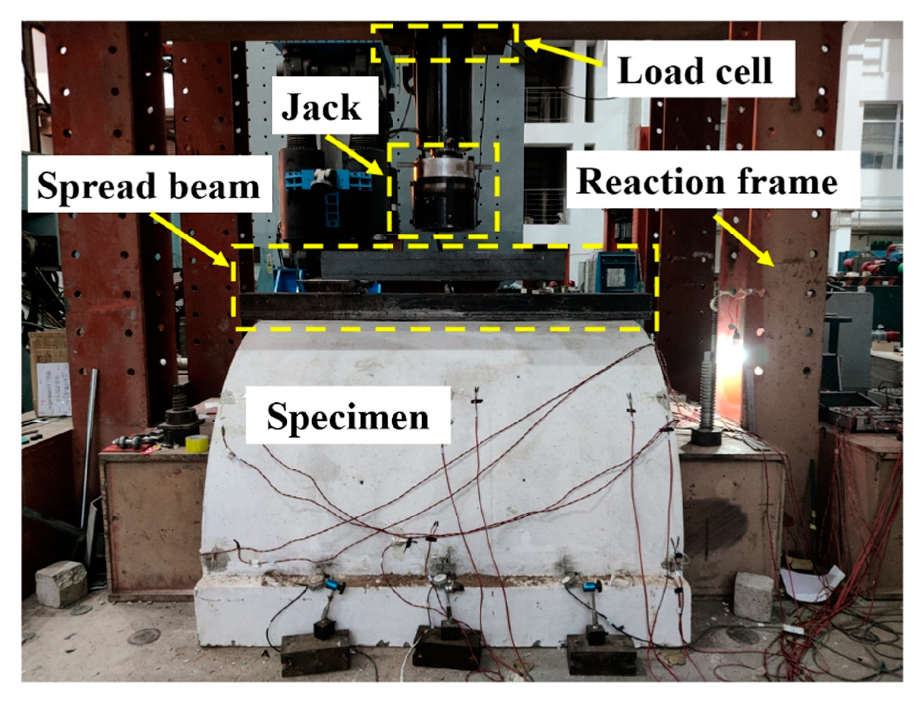
To measure the residual bearing capacity of the tunnel after being subjected to internal blast loads, static tests were conducted on the tunnel. In the static bearing capacity test, five tests were carried out on the tunnel after the explosion of 0 kg (recorded as case B0), 1 kg (corresponding to case B1 in Table 1), and 2 kg (corresponding to cases B2, B3, and B4 in Table 1) of explosives. The static test setup is shown in Figure 3. In tunnel bearing capacity tests, expansion beams are placed on the tunnel roof to ensure that the uniform load applied to the tunnel roof is evenly distributed. At the same time, apply point loads to the upper surface of the extension beam with a hydraulic machine.
Figure 3.
Static bearing capacity test of tunnel (Data from reference [29]).
2.2. Development of Numerical Simulation Model
2.2.1. Numerical Simulation Methods
The finite element model of the tunnel includes reinforcing bars and concrete, as shown in Figure 4. The tunnel lining is cast by concrete. The concrete in the tunnel is meshed by solid elements. The reinforcement is meshed by beam elements. The inter-action between beam elements and solid elements is simulated using the keyword *CONSTRAINED_BEAM_IN_SOLID. Relative sliding between the arch lining and the bottom plate is not considered. The contact behavior between the two components is defined by a shared node method. The mesh size significantly impacts the simulation results. Existing research findings [30,31,32,33] indicate that mesh sizes ranging from 10 mm to 30 mm can meet the accuracy requirements for numerical simulations. The mesh is dense in the middle section of the tunnel, while it is sparse on both sides. The mesh size in the middle section of the tunnel is 15 mm. It gradually increases to 20 mm along the X direction. The outer mesh size is 25 mm. The element size of the reinforcing bars is 10 mm. The distribution of the element sizes in the tunnel is summarized in Figure 4.
Figure 4.
Finite element model of the tunnel.
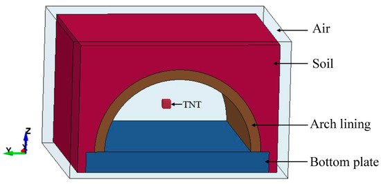
In the internal blast simulation model, air and soil models should be added to the tunnel calculation model, as detailed in Figure 5. Explosives and air adopt the ALE multi-material element algorithm. The mesh size settings for air and soil are the same as those for the tunnel lining described above, but the size of the middle section is 10 mm. The Arbitrary Lagrangian–Eulerian algorithm is applied to simulate the impact of blast loads on the structures. The keyword *INITIAL_VOLUME_FRACTION_GEOMETRY determines the size and shape of the explosive. The contact interaction between the soil and the tunnel is set to surface-to-surface contact by the keyword *CONTACT_AUTOMATIC_SURFACE_TO_SURFACE. The bottom surface of the tunnel is set at a fixed constraint. Non-reflecting boundary conditions are applied at the boundary between air and soil using the keyword *BOUNDARY_NON_REFLECTING, including the six boundary surfaces of the air model, and the sides and bottom of the soil model.
Figure 5.
Finite element model of tunnel subjected to internal blast loads.
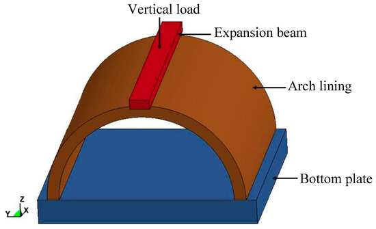
In the static bearing capacity simulation of the tunnel, the loading method of the field test was adopted to design the analysis model, as shown in Figure 6. The element size for the expansion beam that applies a uniform load is 20 mm. The constraint on the vertical translational motion of the loading beam is released, and fixed constraints are set at the bottom of the tunnel. The expansion beam compresses the top of the tunnel lining at a constant speed (0.1 mm/ms) in the vertical direction. The contact interaction between the expansion beam and the tunnel lining is defined using the keyword *CONTACT_AUTOMATIC_SURFACE_TO_SURFACE.
Figure 6.
Finite element model of tunnel under static loading.
The calculation process for determining the residual bearing capacity of a tunnel after exposure to blast loads is separated into three stages:
- Stage 1: Application of blast loads (see Figure 5 for calculation model).
- Stage 2: Free vibration stage of the tunnel. At the same time, to improve the computational efficiency of this stage, the air, explosives, and soil in Figure 5 need to be removed.
- Stage 3: Static loading stage (see Figure 6 for the calculation model).
The restart technology is employed to transfer data among different stages.
2.2.2. Material Models and Parameters
Concrete damage under blast loads is described by the Karagozian & Case Concrete (KCC) model, which takes strain rate effects into account. The KCC model has three independent strength surfaces, namely the residual strength surface, the maximum strength surface, and the yield strength surface. Eight parameters can define three strength planes, as expressed below [34]:
where is pressure; is effective yield strength; is effective failure strength; and is effective residual strength.; , , , , , , , , is the strength surface parameters.
The KCC model parameters for concrete are listed in Table 2.
Table 2.
Parameters of the KCC model for concrete.
The relationship between hydrostatic pressure and bulk modulus in the KCC model is described using the state equation (EOS_TABULATED_COMPACTION). This state equation describes the relationship between the volumetric strain and pressure (for loading), or the volumetric strain and the bulk modulus (for unloading). The parameters of the state equation are given in Table 3.
Table 3.
State equation parameters of concrete.
The dynamic increase factor (DIF) is an important parameter that describes the strain rate effect of materials. In the current study, the DIF equations of compressive strength and tensile strength of concrete [35] are as follows:
where CDIFc and CDIFt are compressive DIF and tensile DIF, respectively; fcd and fcs are dynamic compressive strength and static compressive strength, respectively; ftd and fts are dynamic tensile strength and static tensile strength, respectively; is strain rate. To observe the extent of damage to concrete under explosive loads, the keyword *MAT_ADD_EROSION is used to set the maximum principal strain as the failure criterion, thereby simulating the failure and spalling of concrete. The maximum principal strain parameter for the concrete model is set to 0.1. When the maximum principal strain of an element exceeds 0.1, that element is deleted.
The material model for reinforcing bars is the kinematic hardening plastic model (*MAT_PLASTIC_KINEMATIC). The strain rate effect of reinforcing bars is simulated using the Cowper-Symonds Strain Rate Model (CS model). The relationship between the dynamic amplification coefficient and strain rate is expressed as follows:
where is the strain rate; C and pcs are the strain rate parameters of the CS model. The material parameters of the reinforcing bars are summarized in Table 4.
Table 4.
Material parameters of reinforcing bars.
Air is simulated as an ideal gas. The null material model (*MAT_NULL) and linear polynomial state equation (*EOS_LINEAR_POLYNOMIAL) are employed to simulate air. The linear polynomial state equation can be written as:
where μ = ρ/ρ0 − 1; ρ is the current density; ρ0 is the initial density; P is the air pressure; E0 is the initial internal energy per unit volume; C0, C1, C2, C3, C4, C5, and C6 are constants. The material parameters for air are shown in Table 5.
Table 5.
Material parameters of air.
TNT explosive is simulated by high explosive material model (* MAT_HIGH_EXPLOSIVE_BURN) and JWL equation of state. The JWL state equation can be described as:
where P is the blast pressure; E0 is the initial internal energy per unit volume; V is the relative volume of the detonation products; A, B, R1, R2, and ω are the coefficients of the JWL state equation. The material parameters [29] of TNT explosives are shown in Table 6.
Table 6.
Material parameters of TNT explosives.
The soil is defined by Drucker-Prager model (*MAT_DRUCKER_PRAGER). The stress yield function of Drucker-Prager model is as follows:
where α and k are material parameters related to cohesion and internal friction angle; I1 is the first stress invariant, and J2 is the second deviatoric stress invariant. The material parameters of soil [36,37,38] are shown in Table 7.
Table 7.
Material parameters of soil [36,37,38].
2.3. Validation of Numerical Simulation Model
2.3.1. Comparison of Reflected Overpressure
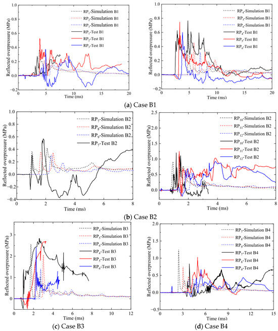
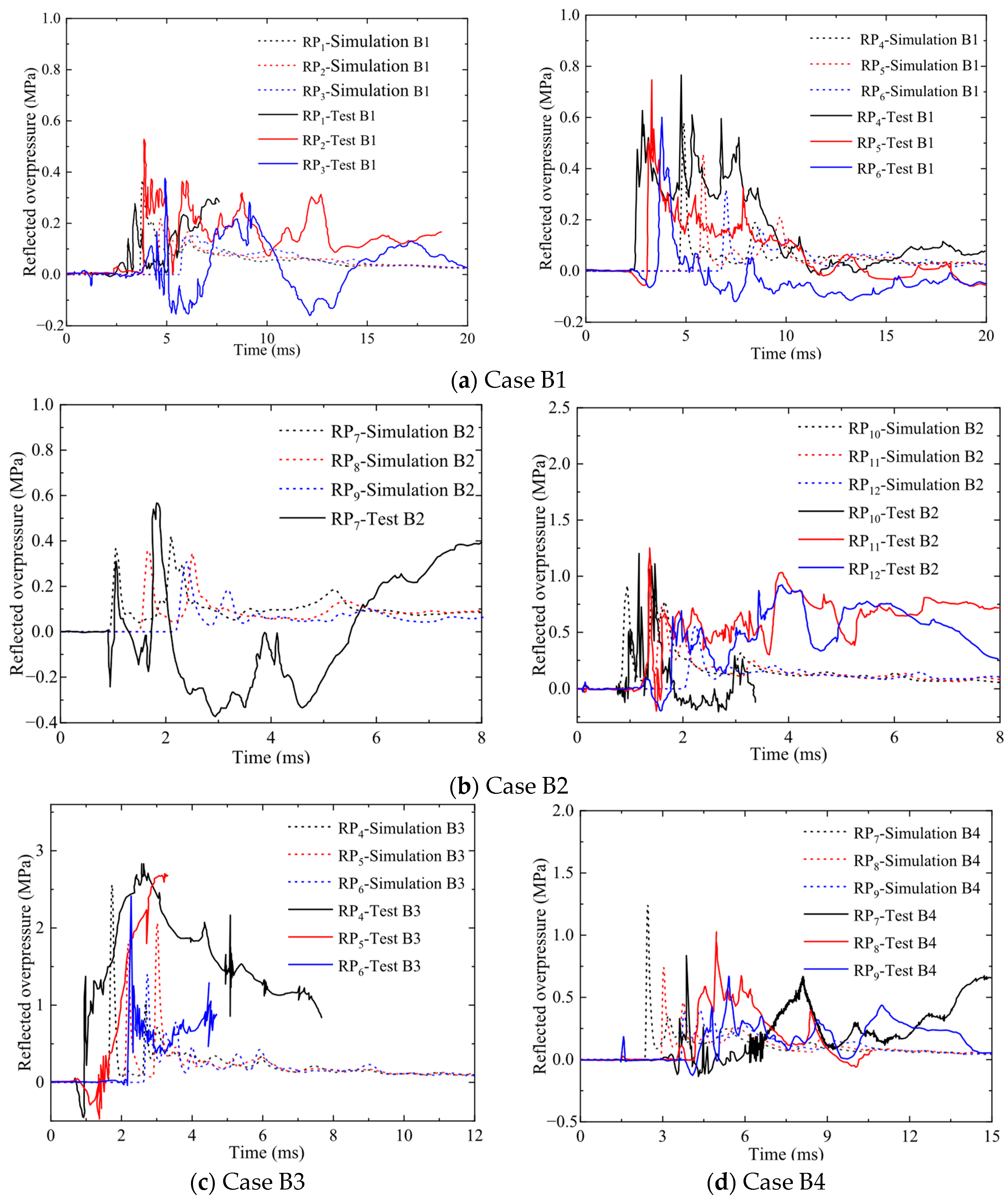
Figure 7 displays a comparison of the reflected overpressure time histories obtained from numerical simulation and test data. It is shown that the simulated values and experimental data for the time at which the blast wave contacts the inner wall surface of the lining are nearly synchronous. Furthermore, the trends in the overpressure-time curves from the simulation and test are identical. Table 8 provides a comparative analysis of peak reflected overpressure between simulation and test results. In Table 8, the errors between the simulation and tests are mainly within 30%. However, there is a significant deviation between the test data and the simulation results. This is due to the complexity of multiple reflections and superposition effects of blast waves inside the tunnel, which makes data collection difficult. In addition, soil disturbance can affect the data collected by sensors [29]. In summary, the arrival time and trend of the simulated reflected overpressure are consistent with the test results. Therefore, the above numerical simulation model can effectively simulate the effect of blast loads on tunnel linings.
Figure 7.
Comparison of reflection overpressure time histories between simulation and test (The test data is sourced from Ref. [29]).
Table 8.
Comparison of peak overpressure between simulation and test (the test data is sourced from Ref. [29]).
2.3.2. Comparison of Damage State
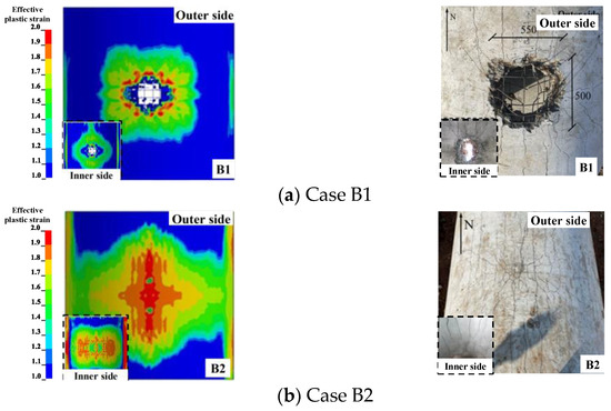
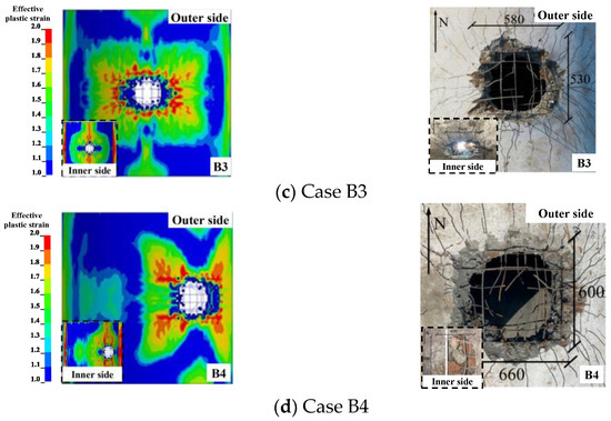
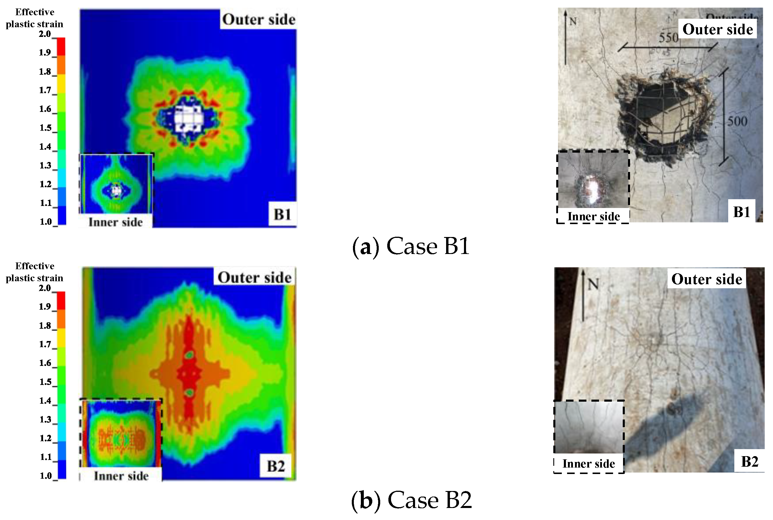
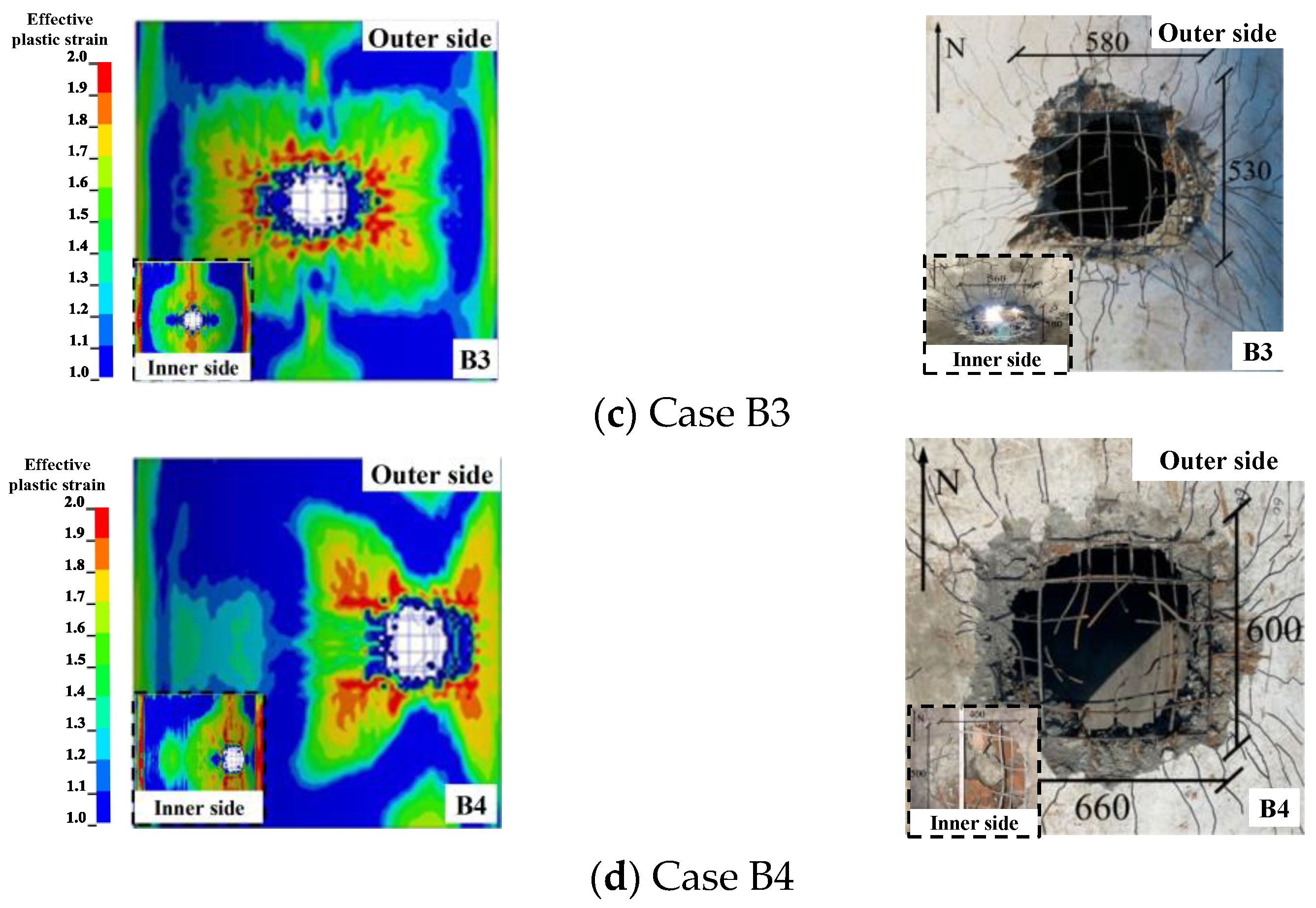
In the comparison of damage states of test specimens in Figure 8 between simulation and test [29], the damage state of the tunnel lining in the simulation and test is the same; that is, cavities appear in the tunnel lining exposed to contact explosions (Cases B1, B3, and B4). However, this phenomenon does not occur in non-contact explosions (Case B2). In addition, the crack propagation directions in the simulations and tests for each test condition are basically consistent. Table 9 shows a comparison of the dimensions of concrete spalling areas in tunnel linings. In Table 9, the error in the dimensions of the spalling areas on the inner and outer sides of the tunnel lining does not exceed 20.0%. This indicates that the error between the simulation results and test results in this paper is small for the damage state of the tunnel lining under internal blast loads. Therefore, it is feasible to study the damage state of tunnel lining under internal explosion using the numerical simulation method described in Section 2.2.1 of this paper.
Figure 8.
Comparison of damage states of tunnel (Left: Simulation; Right: Test. Test data from Ref. [29]).
Table 9.
Comparison of the dimensions of concrete spalling areas between simulation and test (The test data is sourced from Ref. [29]).
2.3.3. Comparison of Bearing Capacity
Table 10 shows a comparison of the bearing capacities of tunnel obtained from the simulation and the test. The data in Table 10 shows that when the charge is located at the waist of the arch (case B4), the error between the simulated and experimental bearing capacity is the largest (i.e., 10.8%). When the charge weight changes (cases B0 and B1) and the charge location changes (cases B2 and B3), the maximum and minimum bearing capacity errors between the simulation and the test are 7.2% and 5.0%, respectively. This indicates that the bearing capacity obtained by the numerical simulation method in this paper can be closely matched with the test data. Therefore, it is feasible to use the numerical simulation method described in Section 2.2.1 of this paper to obtain the bearing capacity of the tunnel.
Table 10.
Comparison of simulated and experimental bearing capacity of tunnel (The test data is sourced from Ref. [29]).
3. Numerical Model of Blast Dynamic Response of Twin-Channel Tunnel
Section 2 of this paper verifies the reliability of the numerical simulation method for internal explosions and bearing capacity of a single-channel tunnel. In this section, the numerical simulation method for single-channel tunnels is extended to twin-channel tunnels. Thus, the damage state and vulnerability analysis of twin-channel tunnels is carried out. It is expected that the numerical simulation study in this section will provide a basis for the design of blast protection for twin-channel tunnels.
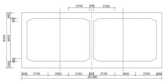
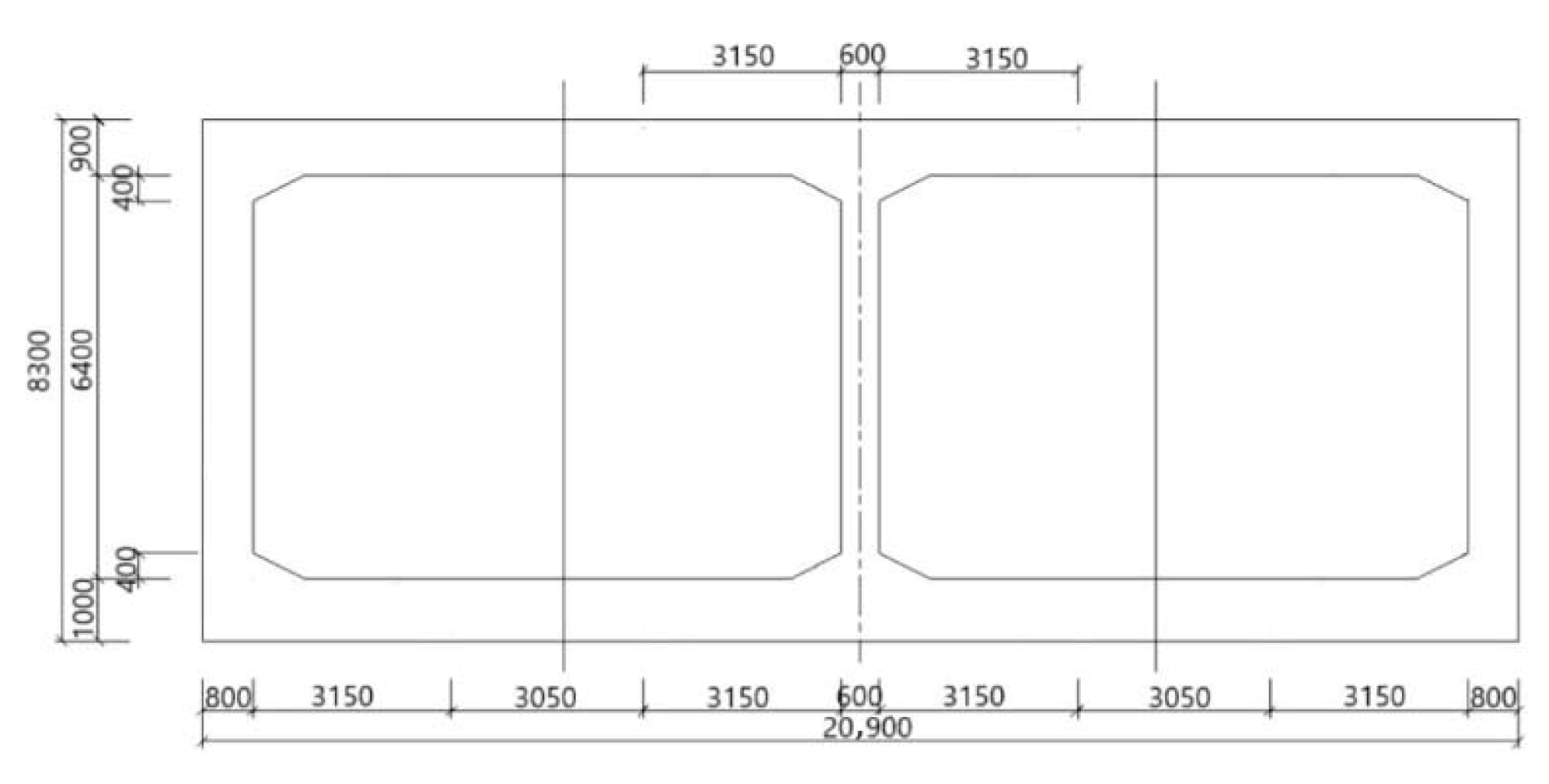
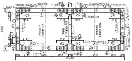
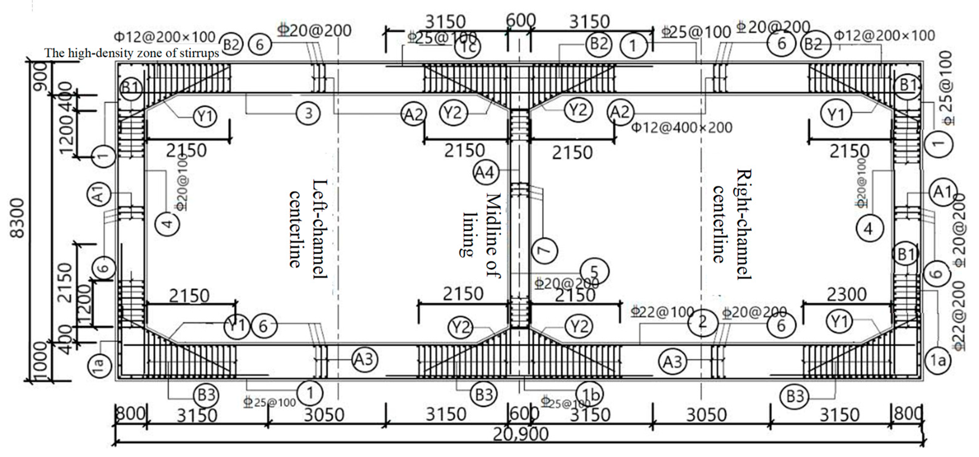
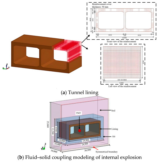
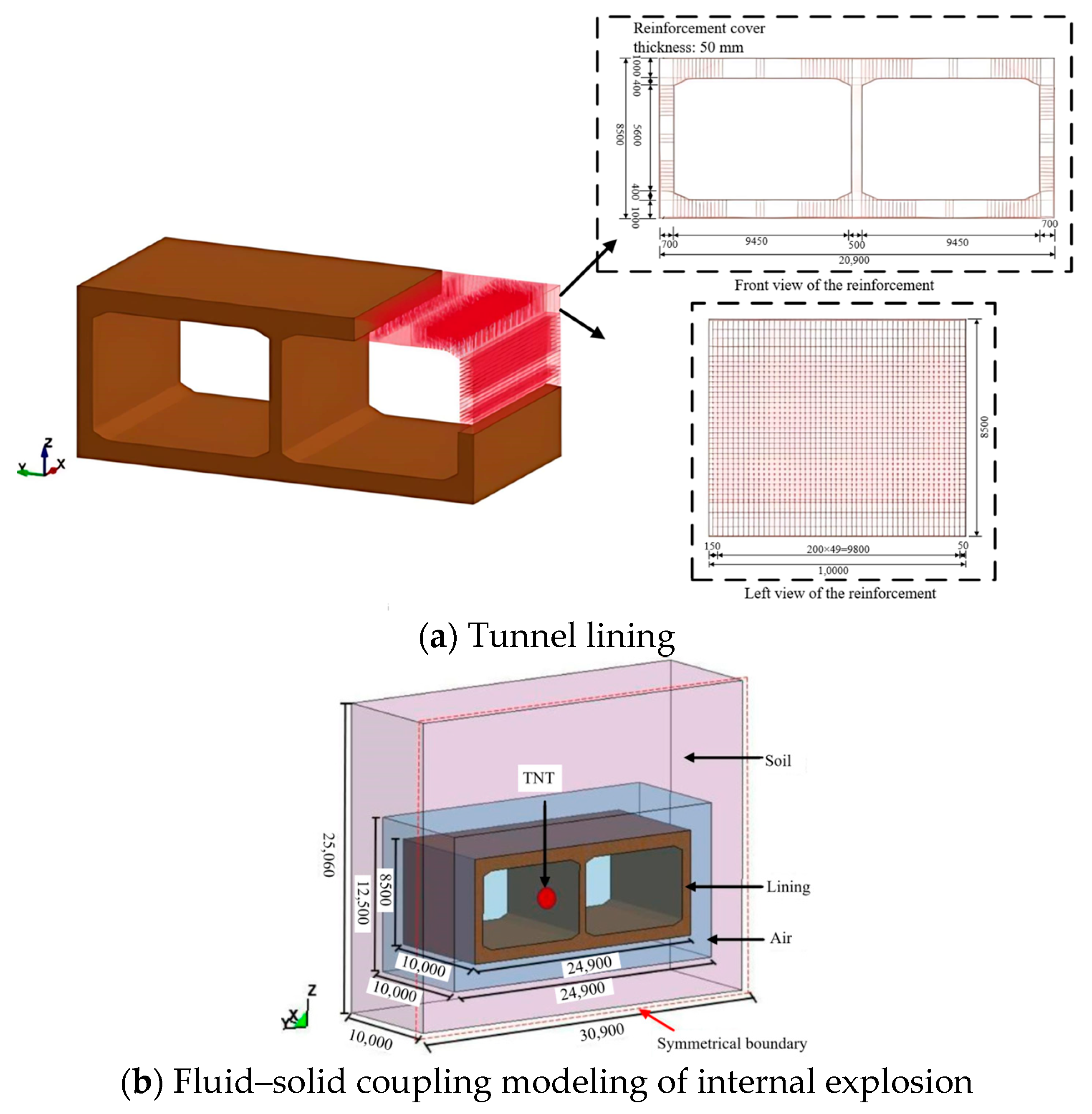
In this section, a finite element model of a twin-channel tunnel in the Lingkong Economic Zone of Ziyang City, Sichuan Province, China, is developed as an example. After that, the dynamic response, damage state and vulnerability of the twin-channel tunnel under internal blasting loads are analyzed. The cross-sectional dimensions of the twin-channel tunnel are shown in Figure 9. The cover thickness of the twin-channel tunnel is 11.56 m. The cross-section of the twin-channel tunnel is rectangular. The total length of the twin-channel tunnel is 1130 m. The thickness of the tunnel roof and floor is 1000 mm. The thickness of the sides and center wall is 800 mm and 500 mm, respectively. The concrete grade of the tunnel is C40. The models of main reinforcement, stiffener, and distributed reinforcement are HRB400. Stirrup and tie bar are HPB300. The diameter of the reinforcing bars for the side and center walls is 20 mm. The diameter of the stirrups is 12 mm. The diameter of the reinforcing bars for the top and bottom plates is 25 mm. The diameter of the stirrups is 12 mm. The thickness of the cover layer for the reinforcing bars is 50 mm. The reinforcement configuration of the tunnel is shown in Figure 10.
Figure 9.
Cross-sectional dimensions of the twin-channel tunnel (unit: mm).
Figure 10.
Reinforcement layout of the twin-channel tunnel (unit: mm).
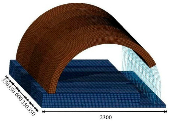
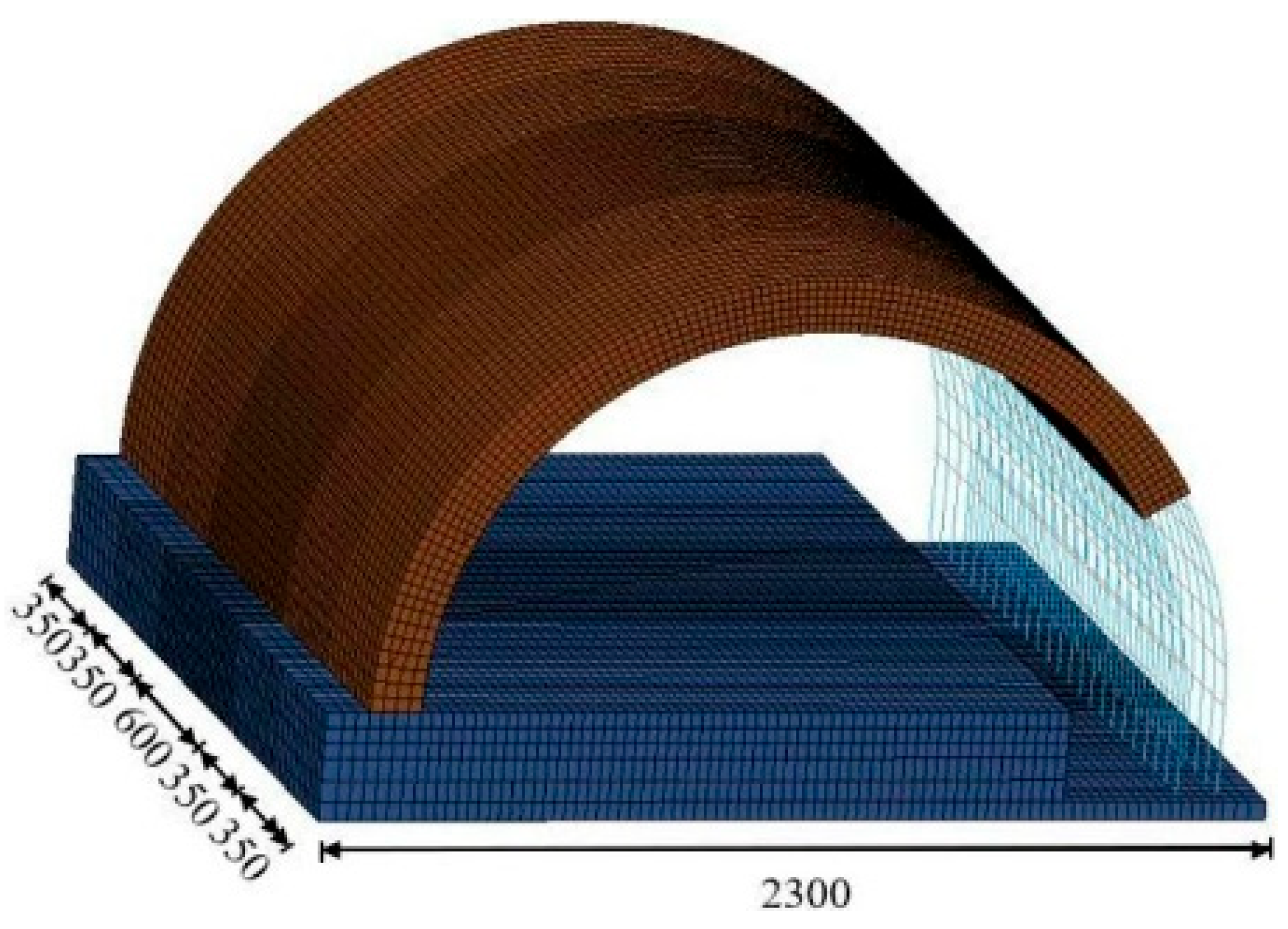
A finite element model of the twin-channel tunnel under internal explosion was established using the numerical simulation method described in Section 2.2.1. Since the twin-channel tunnel is symmetrical in its longitudinal direction, a 1/2 calculation model was established, as shown in Figure 11. The length of the soil boundary from the side wall or the bottom plate of the tunnel is 5 m. The keywords *LOAD_BODY_Z and *CONTROL_DYNAMIC_RELAXTION are used to apply gravity to the soil and tunnel, thereby simulating the soil pressure acting on the tunnel. The rotation of the tunnel symmetry surface in the Y and Z directions and the translation in the X direction are constrained. The six boundary surfaces of the air and the five boundary surfaces of the soil (excluding the top surface) are treated with non-reflective boundary conditions.
Figure 11.
Finite element model of the twin-channel tunnel under internal blast loading.
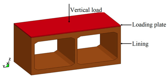
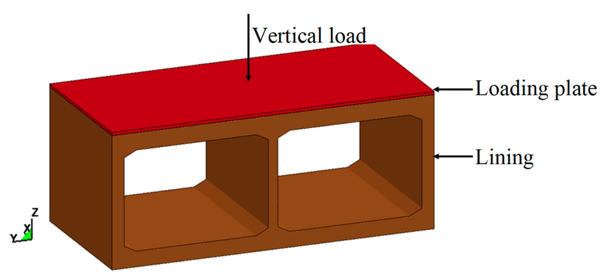
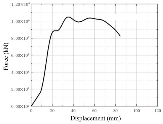
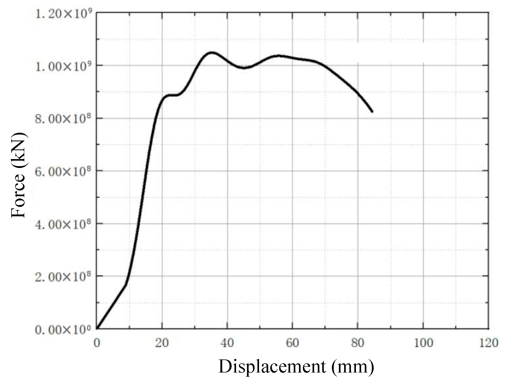
A finite element model of the twin-channel tunnel under static load was established using the numerical simulation method described in Section 2.2.1 (Figure 12). In Figure 12, a plate is placed on top of the tunnel lining to simulate the uniform load on the top of the tunnel. The plate moves vertically at a velocity of 0.1 mm/ms to simulate vertical loading on the top of the tunnel lining. The initial bearing capacity of the twin-channel tunnel that has not been subjected to explosive forces is obtained using the numerical simulation method described in Section 2.2.1. Figure 13 shows the relationship between the applied force and displacement of the tunnel lining. It can be seen that the ultimate bearing capacity of the tunnel is 1.07 × 10⁶ kN, which is the bearing capacity of a tunnel without damage.
Figure 12.
Finite element model of the twin-channel tunnel under static loading.
Figure 13.
Relationship between force and displacement in a twin-channel tunnel under no blast load.
4. Simulation Results and Discussion
4.1. Internal Blast Conditions in the Twin-Channel Tunnel
This paper investigates the influence of four types of explosive threats on tunnels, namely compact sedan, sedan, van, and delivery van. The maximum explosive weight that every type of vehicle can carry is shown in Table 11 [39].
Table 11.
Types of explosion threats.
4.2. Structural Damage State Analysis
4.2.1. The Effect of Charge Weight
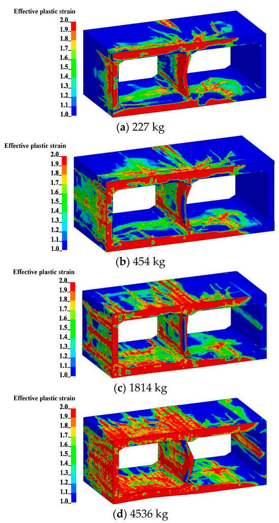
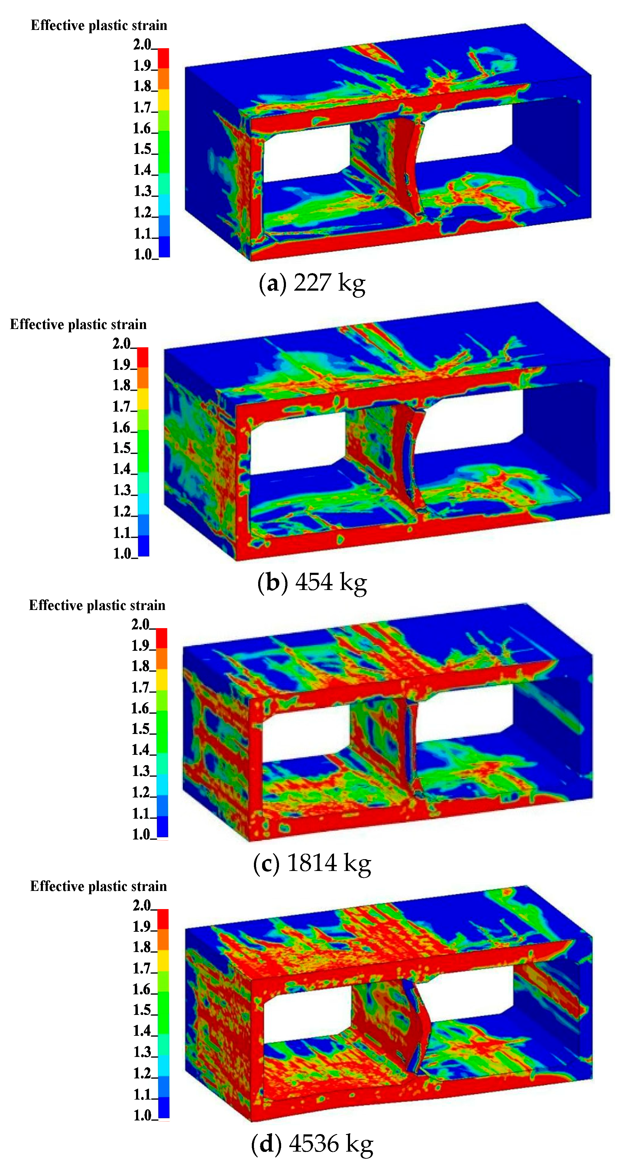
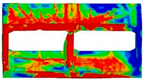
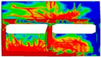
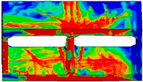
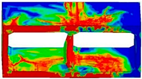
When the charge position is at the center of the left channel of the twin-channel tunnel, the effect of charge weight on tunnel damage state (represented by effective plastic strain) is shown in Figure 14. At a charge weight of 227 kg, the plastic zone of the twin-channel tunnel is mainly located at the charge position, i.e., the left channel of the tunnel. The shock wave generated by the explosion first acts on the left channel lining, causing the inner side of the left channel lining to be subjected to pressure. Under unilateral internal explosion effects, the earth pressure reduces the external tensile stress on the top slab, bottom slab, and side walls of the lining in the left tunnel, thereby enhancing its blast resistance. Therefore, the supporting effect of the soil can improve the tunnel’s blast resistance. However, the middle wall has no soil support, and there is stress concentration in the connection region between the wall and the plate. This resulted in damage to the concrete at the end of the center wall (the connection region between the center wall and the plate was not damaged). In the lining of the non-blasting channel (the right channel of the twin-channel tunnel), plastic strain appeared on the top and bottom plates near the center wall. However, no plastic strain was observed on the outer wall. This indicates that the impact of single-sided blast loads on uncharged channel linings is limited. At the same time, increasing the thickness of the connection region between the wall and the plate can prevent damage to the connection region. Under single-sided internal blast loads, longitudinal cracks in the twin-channel tunnels are primarily distributed near the connection regions between walls and plates. This is the result of the combined effects of stress concentration [40], blast load distribution characteristics [8], soil-structure interaction [41], and tunnel structural characteristics [42,43]. As the weight of the explosives increases, plastic strain in the longitudinal distribution first occurs at the ends and middle of the walls and plates of the twin-channel tunnel, and then gradually spreads to both sides. As the weight of the explosives increases, the area occupied by plastic strain in the left channel of the twin-channel tunnel increases, and the plastic strain in the roof and floor of the right channel gradually extends along the roof and floor to the right wall, ultimately producing plastic strain at the end and middle of the right outer wall of the tunnel. When the charge weight is low (M ≤ 1814 kg), the concrete at the right end of the center wall fails and falls off, and the center wall deflects to the left. When the charge weight is large (M > 1814 kg), the concrete in the middle and left end of the center wall is damaged, and the center wall deflects to the right. Also, the roof and floor of the left tunnel of the twin-channel tunnel are moving inward. This may be the result of multiple factors acting in concert. On one hand, the blast overpressure includes a negative pressure phase. This causes tensile stress to act on the lining. On the other hand, single-channel internal explosion loads can change the relative bearing capacity of twin-channel linings. Under the action of earth pressure, the relative bearing capacity of the twin-channel lining is further weakened, thereby affecting the overall damage state of the tunnel. At the same time, the damage state of the central wall also plays an important role. Increasing the charge weight will exacerbate damage to the central wall of the tunnel. The collapse of the central wall will severely affect the overall structural stability of the twin-channel tunnel. Therefore, the relative load-bearing capacity of the twin-channel linings, the damage level of the center wall, and the earth pressure will collectively influence the damage state of the twin-channel tunnel. However, the mechanism of this synergistic effect still requires further in-depth investigation.
Figure 14.
Effect of charge weight on tunnel damage state.
4.2.2. The Effect of the Charging Location
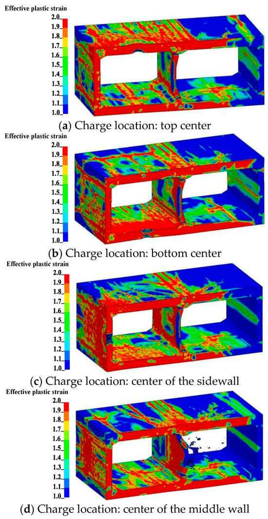
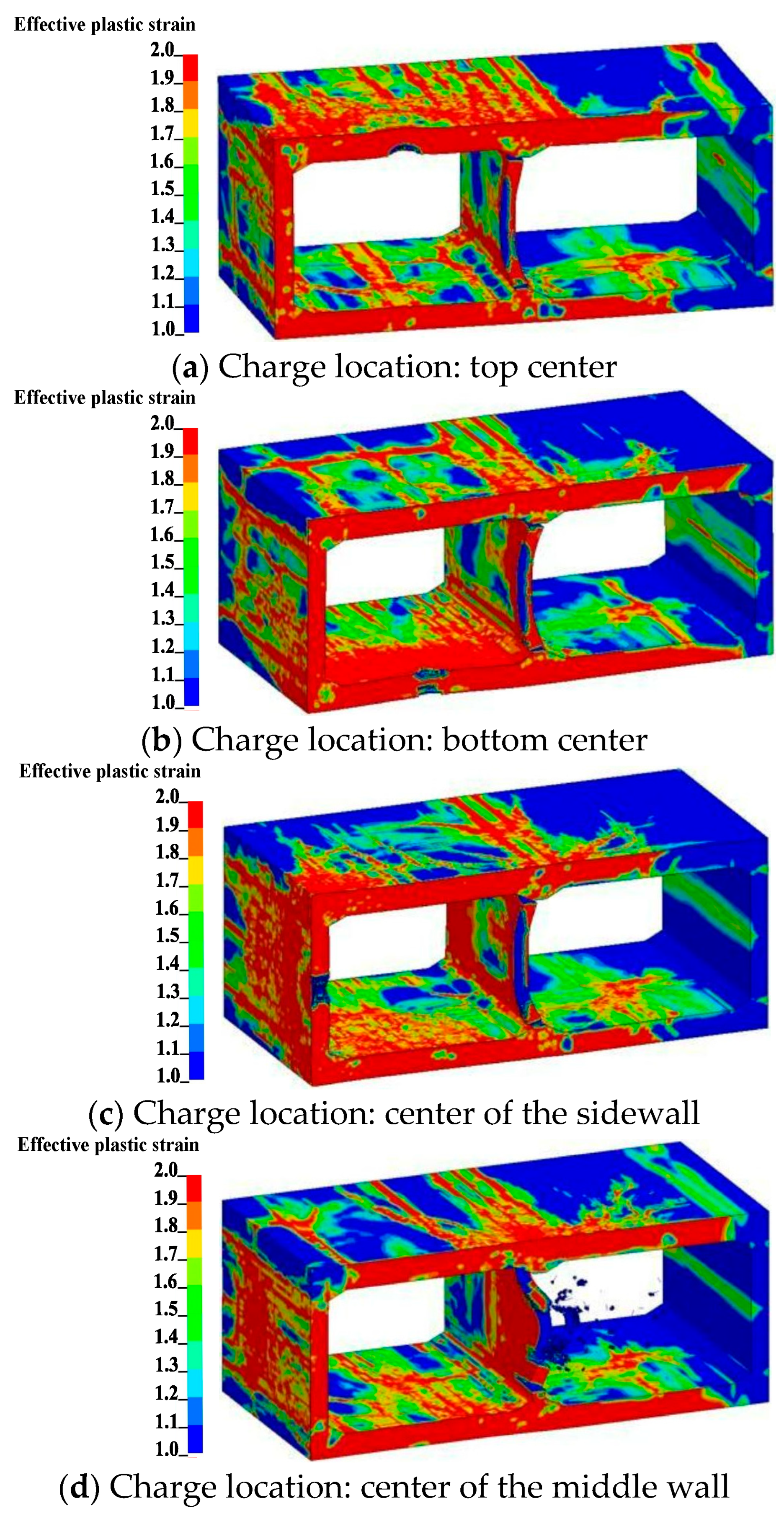
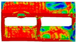
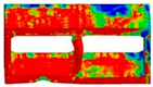
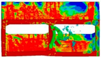
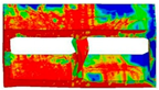
When the charge weight is 1814 kg and at the left channel of the twin-channel tunnel, the effect of the explosive location on the damage state of the tunnel (represented by effective plastic strain) is shown in Figure 15. When the explosives were placed at the top, bottom, and center of the side walls of the left channel, the concrete lining closest to the explosives suffered localized damage, while the top and bottom plates remained intact. Meanwhile, the concrete at both ends of the middle wall was damaged and shifted to the left. When the charge location is at the center of the middle wall of the left channel, local damage occurs in the middle and end of the middle wall, and it shifts to the right side. This indicates that the pressure of the soil enhances the ability of the external lining of the tunnel to resist blast loads. However, the earth pressure does not act on the middle wall, and the pressure exerted by the earth pressure on the top and bottom plates will exacerbate the damage to the middle wall. When explosives are placed in the top slab, bottom slab, and outer wall of the left-channel lining, the effective plastic strain in the outer wall of the right-channel lining is significantly greater than that when charges are placed in the center wall. Additionally, when explosives are placed in the central wall, its collapse will reduce the overall load-bearing capacity of the twin-channel tunnel. This indicates that the charge location significantly influences the damage state of the outer wall in the non-explosive channel. In the blast-resistant design of twin-channel tunnels, enhancing the protection level of the central wall is beneficial for strengthening the tunnel’s overall blast resistance. At the same time, reliable blast-resistant protective measures can effectively enhance the bearing capacity of tunnel structures [44].
Figure 15.
Effect of charge location on tunnel damage state.
4.3. Structural Vulnerability Analysis
4.3.1. Uncertainty Analysis of Internal Blast Loads
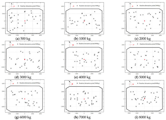
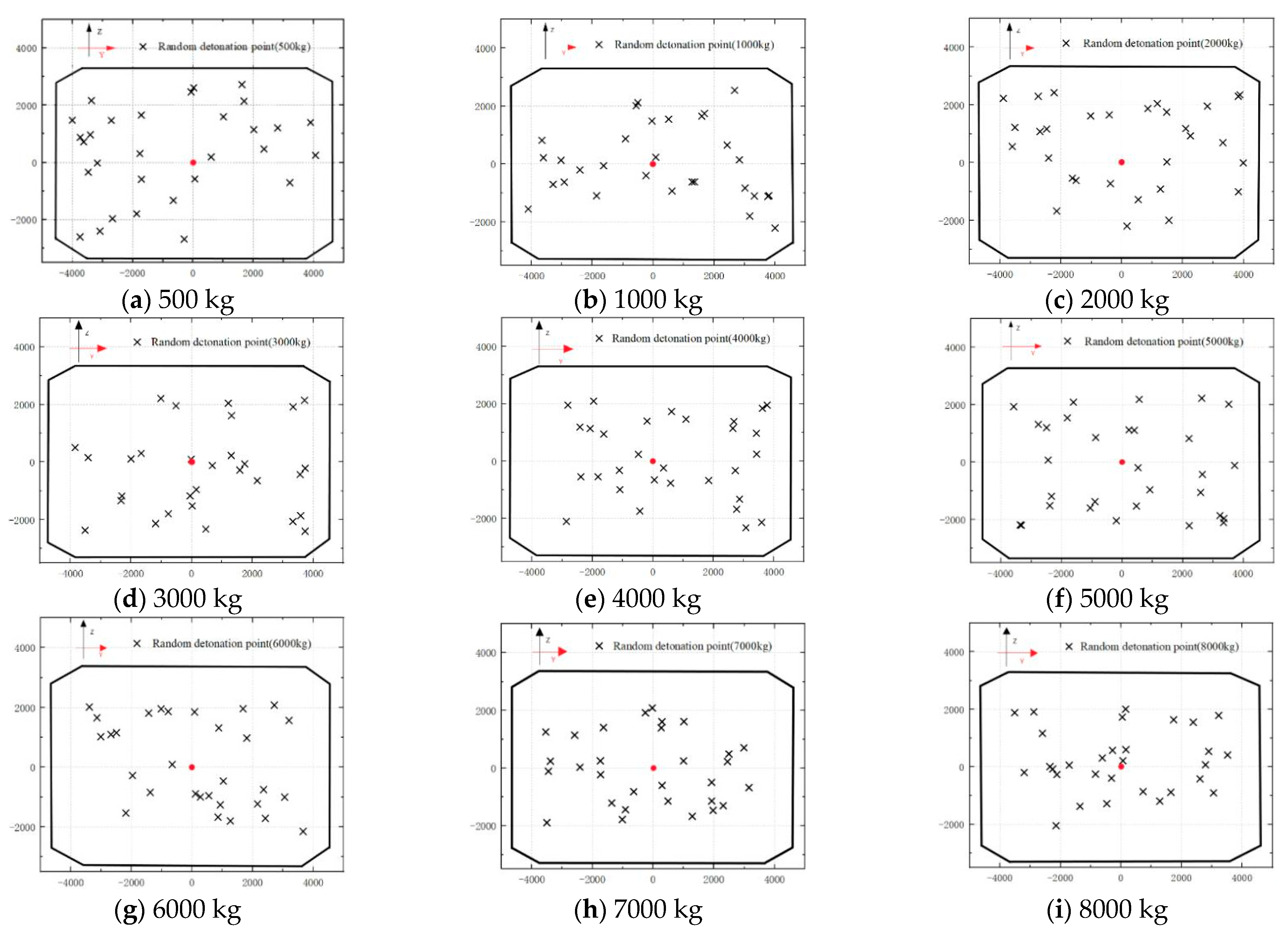
Research on the vulnerability of tunnel under blast loading needs to consider the uncertainty of blast loads [45,46]. This study considers two uncertain factors, namely the charge weight and the charge location. The adopted charge weights are 500 kg, 1000 kg, 2000 kg, 3000 kg, 4000 kg, 5000 kg, 6000 kg, 7000 kg, and 8000 kg, respectively. On the other hand, every weight corresponds to 30 charge locations. The Monte Carlo algorithm is used to perform random sampling on one side of the twin-channel tunnel to determine the charge location [47]. Figure 16 shows the random distribution of detonation points for different charge weights. Based on the combination of different charge weights and locations, 270 simulation cases were performed for the vulnerability analysis of the twin-channel tunnel.
Figure 16.
Distribution of charge location for every charge weight.
4.3.2. Determining the Index and Level of Damage
The damage index can intuitively and accurately reflect the deterioration of the mechanical properties of a tunnel after a blast impact [48]. In this paper, the bearing capacity is used as the damage index [49] to evaluate the damage level of the tunnel after blast loading. The expression of the damage index is as follows:
where Fr is the residual bearing capacity of the tunnel after blast loading, and F0 is the initial bearing capacity before blast loading. The damage index is an important parameter for quantifying the damage level. The higher the value of damage index is, the more severe the damage level of the tunnel. Based on the differences in damage index values, the damage level of tunnel can be classified into four grades [50]: minor damage, moderate damage, severe damage, and collapse. The scopes of the damage index for every damage level are shown in Table 12.
Table 12.
Scopes of damage index for different damage level.
4.3.3. Damage Level Analysis
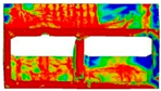
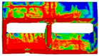
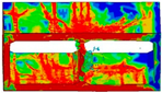
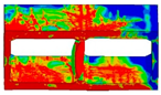
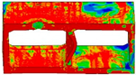
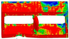
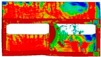
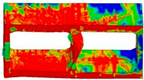
Numerical simulation was conducted on the damage level of tunnel lining for different charge weights and charge locations, and the vulnerability analysis of the tunnel was performed based on the simulation results. For charge weights of 500 kg, 2000 kg, 6000 kg, and 8000 kg (the charging location is the middle of various parts of the left channel of the twin-channel tunnel, including the roof, floor, center wall, and left wall), the simulation results of the damage state (described by the effective plastic strain) and residual bearing capacity of the twin-channel tunnel are shown in Table 13 and Table 14, respectively. In Table 13, an increase in charge mass leads to greater damage to the tunnel. At the same time, the damage to the tunnel lining near the explosives is severe. In Table 14, the damage index of the tunnel shows an increasing trend with the increase in charge weight. This indicates that increasing the charge weight exacerbates the damage to the tunnel. Additionally, when charges are placed on the middle and left walls, the damage index of a twin-channel tunnel is greater than when charges are placed on the top and bottom floors. Therefore, placing explosives on the tunnel walls will increase the damage level of the twin-channel tunnel.
Table 13.
Damage state of twin-channel tunnel for different charge weights and locations (effective plastic strain diagram).
Table 14.
Residual bearing capacity and damage level of twin-channel tunnel for different charge weights and locations.
4.3.4. Vulnerability Assessment
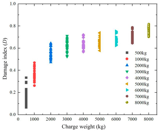
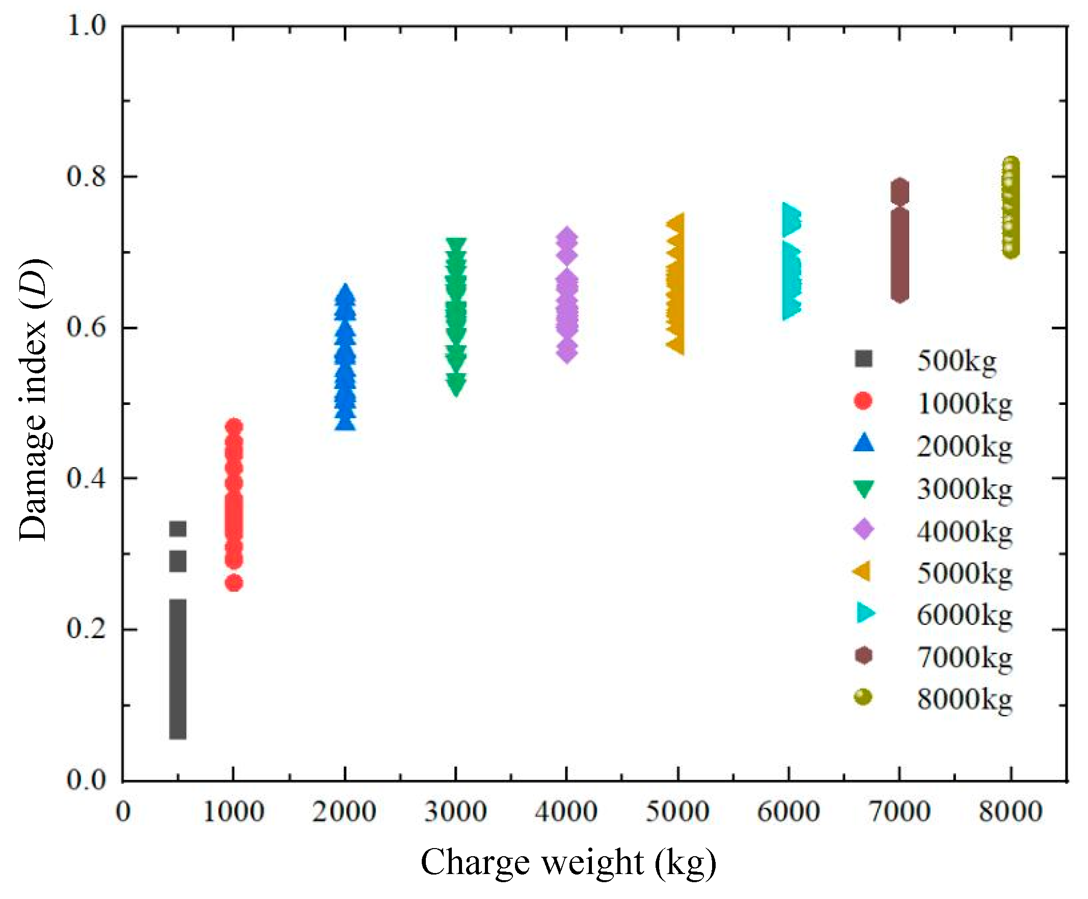
The residual bearing capacity of the twin-channel tunnel for 270 loading cases was calculated, and the corresponding damage indices were obtained. The relationship between the damage index and the charge weight is shown in Figure 17. It is shown that when the charge weight is in the range of 500 kg to 8000 kg, the damage index increases with the increase in charge weight. The damage index increases rapidly between 500 kg and 2000 kg. This indicates that the damage level increases significantly when the charge weight varies within this range. When the charge weight is within the range of 2000 kg to 8000 kg, the damage index increases slowly. This indicates that the damage level does not increase significantly when the charge weight varies within this range.
Figure 17.
Relationship between the damage index and the charge weight.
Statistical analysis was performed on 270 sample datasets. It was assumed that the damage index followed a logarithmic distribution for the same charge weight [51,52]. The mean and standard deviation of the logarithmic values of damage index were calculated for different charge weights. The corresponding results are summarized in Table 15.
Table 15.
Mean and standard deviation of the logarithmic values of damage indices for different charge weights.
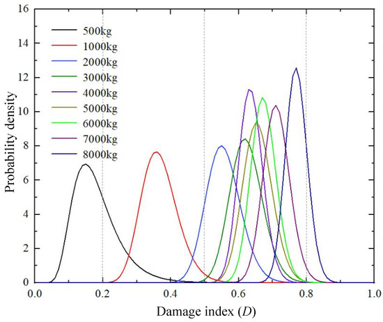
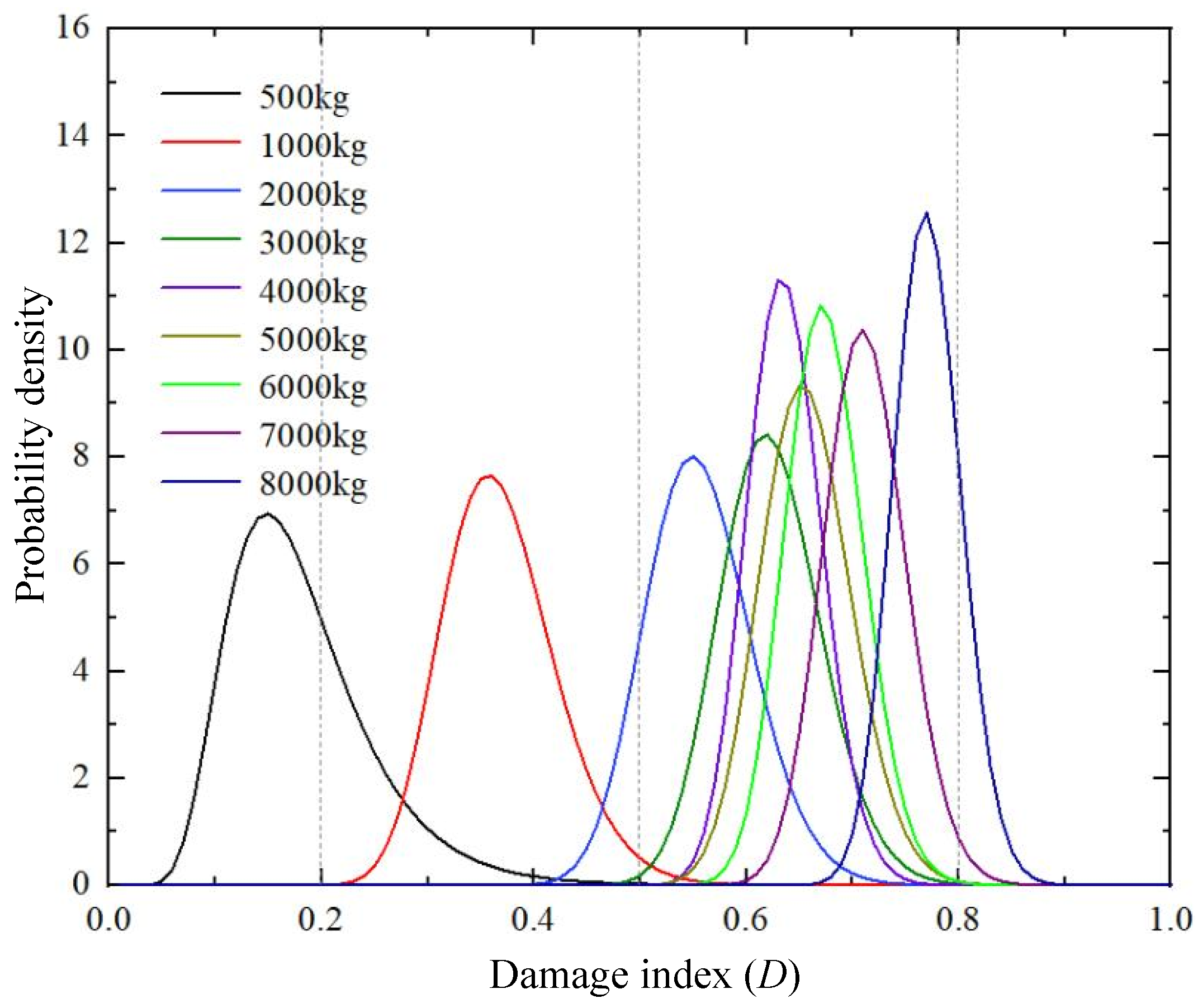
The probability density curve plotted based on the mean and standard deviation in Table 15 is illustrated in Figure 18. The values of the vertical dotted lines are the boundary values of the damage index for the four damage levels. The results in Figure 18 show that as the charge weight increases, the damage index corresponding to the peak of the probability density curve gradually increases, indicating that the damage extent of the tunnel is gradually worsening. When the charge weight is 500 kg, the damage level to the tunnel is mainly minor. When the charge weight is 1000 kg, the damage level to the tunnel is mainly moderate. When the charge weight exceeds 2000 kg, the damage level of the tunnel is mainly severe. When the charge weight exceeds 8000 kg, there is a probability of collapse for the twin-channel tunnel.
Figure 18.
Probability density curves of damage index for different charge weights.
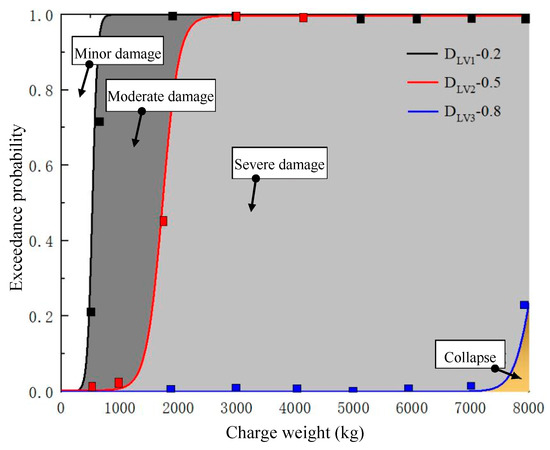
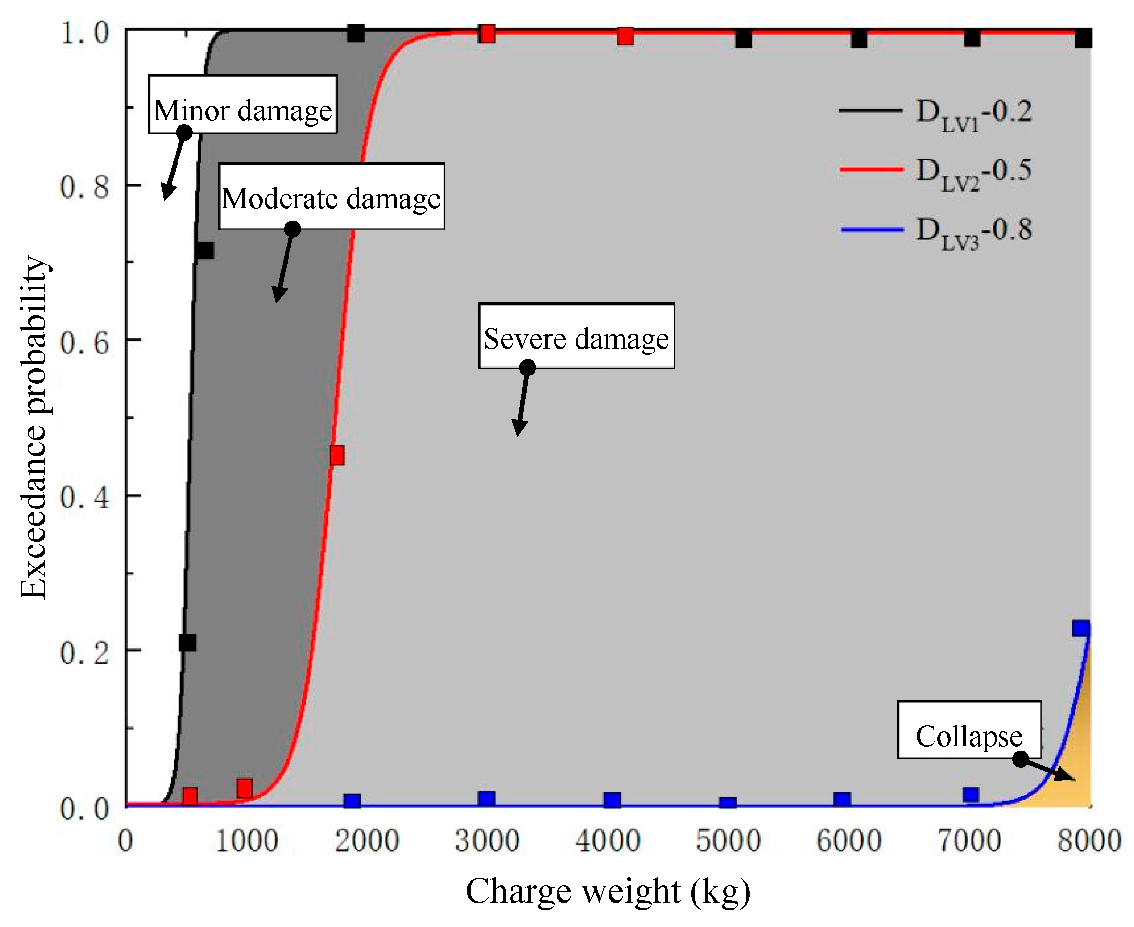
Figure 19 illustrates the vulnerability of the twin-channel tunnel under internal blast loading. The three curves (DLV1, DLV2, DLV3) in the figure divide four regions which correspond to different damage levels. When the charge weight exceeds 1000 kg, the exceedance probability of minor damage approaches 1. When the explosive charge weight reaches 3000 kg, the exceedance probability of severe damage approaches 1. Moreover, the areas of the domains for moderate and severe damage are larger than those of the other domains. This indicates that within the range of 500~8000 kg, the damage level of the twin-channel tunnel is mainly moderate and severe.
Figure 19.
Vulnerability of the twin-channel tunnel under internal blast loading.
5. Conclusions
This paper employs LS-DYNA software (Version: R12) to conduct numerical simulation studies on the damage state and vulnerability of a twin-channel tunnel under single-sided internal blast loading. The research results indicate that:
- (1)
- The thickness of the central wall of the twin-channel tunnel is small, and the earth pressure weakens its bearing capacity. Therefore, the blast resistance of the central wall is poor. Under internal explosion action, the earth pressure reduces the tensile stress on the outer sides of the top slab, bottom slab, and side walls, thereby enhancing their explosion resistance. Unilateral internal explosion loads can cause changes in the relative load-bearing capacity of the twin-channel linings. The relative load-bearing capacity of the twin-channel linings further weakens under the action of earth pressure, thereby affecting the overall damage state of the tunnel. At the same time, the damage state of the central wall also plays an important role. Increasing the thickness of the connection area between the wall and the slab can enhance the blast resistance of that region. As the loading weight increases, the damage to the twin-channel tunnel intensifies. The plastic strain in the top and bottom plates of the non-charged channel gradually propagates along the top and bottom plates. Ultimately, plastic strain appears at the end and mid-section of the right outer wall of the twin-channel tunnel.
- (2)
- The combined effects of structural characteristics and soil-structure interaction cause the deformation and failure patterns of the middle wall to exhibit different phenomena under different charge weights. When the charge weight is low (M ≤ 1814 kg), the concrete at the end of the right side of the center wall fails and falls off, and the center wall deflects to the left. When the charge weight is large (M > 1814 kg), the concrete in the middle and ends of the center wall is damaged, and the center wall deflects to the right. Also, the roof and floor of the left tunnel of the twin-channel tunnel are moving inward.
- (3)
- When explosives were placed on the roof, floor, and outer walls of the twin-channel tunnel (loading weight: 1814 kg), the walls in contact with the explosives suffered localized damage. When explosives are placed on the center wall of the twin-channel tunnel, the concrete at the ends and middle of the center wall is damaged. The charge location has a significant impact on the damage state of the outer wall of the uncharged channel in the twin-channel tunnel. When the charge location is at the top, bottom, and outer wall of the left channel (the channel where explosives are placed) of the tunnel, the effective plastic strain of the outer wall of the right channel is significantly greater than the effective plastic strain when the charge location is at the middle wall.
- (4)
- The damage index increases with increasing charge weight. The damage level of the twin-channel tunnel was mainly slight, moderate, severe, and collapsed for charge weights of 500 kg, 1000 kg, 2000 kg, and 8000 kg, respectively. When the charge weight exceeds 1000 kg, the probability of minor damage reaches 1. When the charge weight reaches 3000 kg, the probability of severe damage reaches 1. The vulnerability diagram developed in this paper allows probabilistic assessment of the damage level of a twin-channel tunnel for different charge weights and blast locations.
- (5)
- This paper suggests the following recommendations in the explosion-resistant design of the twin-channel tunnel: the center wall is the weak part of the twin-channel tunnel. The strengthening of the blast protection level of the center wall is the key to preventing tunnel collapse. The combined TNT-equivalent threshold for vehicles transporting dangerous products in twin-channel tunnels is 300 kg. The combined TNT-equivalent threshold should be reduced when the size of the twin-channel tunnel is smaller than that of this paper.
- (6)
- This article has some shortcomings. Numerical simulation models consume a lot of computational resources. It is necessary to develop a rapid analysis model to assess the vulnerability of twin-channel tunnels under internal explosions. The combined effects of central walls, earth pressure, and internal explosion loads on the damage state and vulnerability of twin-channel tunnels need further investigation. The residual bearing capacity reveals the load-bearing limit of the twin-channel tunnel. However, it is impossible to assess the serviceability limit state of the twin-channel tunnel. In the twin-channel tunnel, the vulnerability curve is influenced by tunnel dimensions. The trend of vulnerability curve changes when tunnel dimensions decrease or increase is unclear.
Author Contributions
Conceptualization, F.L. and Z.L.; methodology, F.L. and Z.L.; validation, F.L. and Z.L.; formal analysis, F.L. and Z.L.; investigation, F.L. and Z.L.; data curation, F.L. and Z.L.; writing—original draft preparation, F.L., Z.L., L.L. and L.W.; writing—review and editing, F.L., Z.L. and L.W.; project administration, F.L., Z.L. and L.L.; funding acquisition, F.L., Z.L. and L.L. All authors have read and agreed to the published version of the manuscript.
Funding
National Natural Science Foundation of China, Grants No. 52278474, 52078288.
Data Availability Statement
The original contributions presented in this study are included in the article. Further inquiries can be directed to the corresponding authors.
Conflicts of Interest
The authors declare no conflicts of interest.
References
- He, B.; Armaghani, D.J.; Lai, S.H.; He, X.; Asteris, P.G.; Sheng, D. A deep dive into tunnel blasting studies between 2000 and 2023-A systematic review. Tunn. Undergr. Space Technol. 2024, 147, 105727. [Google Scholar] [CrossRef] [Scilit]
- Makarov, V.V. Island megalopolises: Tunnel systems as a critical alternative in solving transport problems. Engineering 2018, 4, 138–142. [Google Scholar] [CrossRef] [Scilit]
- Mussa, M.H.; Mutalib, A.A.; Hamid, R.; Naidu, S.R.; Radzi, N.A.M.; Abedini, M. Assessment of damage to an underground box tunnel by a surface explosion. Tunn. Undergr. Space Technol. 2017, 66, 64–76. [Google Scholar] [CrossRef] [Scilit]
- Liu, J.; Yan, Q.; Wu, J. Analysis of blast wave propagation inside tunnel. Trans. Tianjin Univ. 2008, 14, 358–362. [Google Scholar] [CrossRef] [Scilit]
- Duan, J.; Zong, Q.; Wang, H.; Cheng, B.; Gao, P. Study on stress wave propagation and failure characteristics of key parts in tunnel under blasting load. Sci. Rep. 2024, 14, 29034. [Google Scholar] [CrossRef] [Scilit]
- Zhao, D.; Huang, Y.; Chen, X.; Han, K.; Chen, C.; Zhao, X.; Chen, W. Numerical investigations on dynamic responses of subway segmental tunnel lining structures under internal blasts. Tunn. Undergr. Space Technol. 2023, 135, 105058. [Google Scholar] [CrossRef] [Scilit]
- Saeed, A.; Chen, L.; Feng, B. Development and Advance in Tunnel Structures Subjected to Internal Blast Loads: A Comprehensive Review. Arch. Comput. Methods Eng. 2025, 32, 3265–3307. [Google Scholar] [CrossRef] [Scilit]
- Prasanna, R.; Boominathan, A. Finite-element studies on factors influencing the response of underground tunnels subjected to internal explosion. Int. J. Geomech. 2020, 20, 04020089. [Google Scholar] [CrossRef] [Scilit]
- Yu, H.; Wang, Z.; Yuan, Y.; Li, W. Numerical analysis of internal blast effects on underground tunnel in soils. Struct. Infrastruct. Eng. 2016, 12, 1090–1105. [Google Scholar] [CrossRef] [Scilit]
- Liu, C.; Zhao, G.H.; He, J.Z.; Liu, H.; Cui, J. Damage Pattern and Failure Mechanism of Shield Tunnel Lining under Internal Explosion. Thin-Walled Struct. 2025, 214, 113420. [Google Scholar] [CrossRef] [Scilit]
- Zhao, Y.; Chu, C.; Yi, Y. Study on an engineering measure to improve internal explosion resistance capacity of segmental tunnel lining structures. J. Vibroeng. 2016, 18, 2997–3009. [Google Scholar] [CrossRef] [Scilit]
- Xu, L.F.; Chen, L.; Zhang, X.; Yue, C. Investigation on the performances of folded arch immersed tube tunnel under internal explosion. Structures 2025, 79, 109352. [Google Scholar] [CrossRef] [Scilit]
- Cheng, R.; Chen, W.; Hao, H.; Li, J. Dynamic response of road tunnel subjected to internal Boiling liquid expansion vapour explosion (BLEVE). Tunn. Undergr. Space Technol. 2022, 123, 104363. [Google Scholar] [CrossRef] [Scilit]
- Huang, Z.; Qin, M.; Ma, S.; Qiu, C.; Zhou, Y. Mechanical response and blast resistance evaluation of prefabricated frame tunnels with steel box joints under internal explosion. Eng. Sci. Technol. Int. J. 2024, 55, 101752. [Google Scholar] [CrossRef] [Scilit]
- Duan, Y.; Liu, L.; Yang, J.; Long, J.; He, G.; Lei, S.; Duan, X. Effects of explosion-venting interlayer within utility tunnels on the characteristics of natural gas explosions. Fuel 2024, 377, 132766. [Google Scholar] [CrossRef] [Scilit]
- Tiwari, R.; Chakraborty, T.; Matsagar, V. Analysis of curved tunnels in soil subjected to internal blast loading. Acta Geotech. 2020, 15, 509–528. [Google Scholar] [CrossRef] [Scilit]
- Zhong, C.; Sun, Y. Influence of Explosion Point’s Position on the Propagation Law of Shock Wave. In International Conference on Development and Application of Carbon Nanomaterials in Energetic Materials; Springer Nature: Berlin, Germany, 2022; Volume 276, p. 275. [Google Scholar] [CrossRef] [Scilit]
- Dolatshahi, A.; Nouri Qarahasanlou, A. Pre-existing Crack Effect on Damage of Inner Concrete Lining under an Internal Explosion: A Numerical Study. J. Min. Environ. 2023, 14, 945–960. [Google Scholar] [CrossRef]
- Tiwari, R.; Chakraborty, T.; Matsagar, V. Dynamic analysis of tunnel in soil subjected to internal blast loading. Geotech. Geol. Eng. 2017, 35, 1491–1512. [Google Scholar] [CrossRef] [Scilit]
- Ngo, T.; Mendis, P.; Gupta, A.; Ramsay, J. Blast loading and blast effects on structures-an overview. Electron. J. Struct. Eng. 2007, 1, 76–91. [Google Scholar] [CrossRef] [Scilit]
- Liu, H.B. Soil-structure interaction and failure of cast-iron subway tunnels subjected to medium internal blast loading. J. Perform. Constr. Facil. 2012, 26, 691–701. [Google Scholar] [CrossRef] [Scilit]
- Hua, N.; Elhami-Khorasani, N.; Tessari, A. Review of tunnel fire damage assessment methods and techniques. Transp. Res. Rec. 2021, 2675, 279–290. [Google Scholar] [CrossRef] [Scilit]
- Roy, N.; Sarkar, R. A review of seismic damage of mountain tunnels and probable failure mechanisms. Geotech. Geol. Eng. 2017, 35, 1–28. [Google Scholar] [CrossRef] [Scilit]
- Frenelus, W.; Peng, H.; Zhang, J. Long-term degradation, damage and fracture in deep rock tunnels: A review on the effect of excavation methods. Fract. Struct. Integr. 2021, 15, 128–150. [Google Scholar] [CrossRef] [Scilit]
- Mobaraki, B.; Vaghefi, M. Numerical study of the depth and cross-sectional shape of tunnel under surface explosion. Tunn. Undergr. Space Technol. 2015, 47, 114–122. [Google Scholar] [CrossRef] [Scilit]
- Liu, Z.; Wu, J.; Chen, Q.; Li, S.; Yan, Q.; Yu, H. Analysis on the vulnerability of a tunnel entrance under internal explosion. Sensors 2022, 22, 9727. [Google Scholar] [CrossRef] [Scilit]
- Bai, F.T.; Guo, Q.; Root, K.; Naito, C.; Quiel, S. Blast vulnerability assessment of road tunnels with reinforced concrete liners. Transp. Res. Rec. 2018, 2672, 156–164. [Google Scholar] [CrossRef] [Scilit]
- Zhang, C.; Zhang, D.; Huang, Z.; Lei, C.; Zhang, B.; Huang, H. Fragility assessment of shallow buried tunnels under explosive hazards. Tunn. Undergr. Space Technol. 2024, 152, 105909. [Google Scholar] [CrossRef] [Scilit]
- Liu, Z.C.; Wu, J.; Cao, C.; Li, S.; Yan, Q. Dynamic performance and damage assessment of a shallow buried tunnel under internal explosion. Tunn. Undergr. Space Technol. 2023, 133, 104918. [Google Scholar] [CrossRef] [Scilit]
- Zhou, L.Y.; Li, X.J.; Yan, Q.; Li, S.; Chang, S.; Ren, P. Test and damage assessment of shallow buried RC tunnel under explosion. Undergr. Space 2024, 14, 118–137. [Google Scholar] [CrossRef] [Scilit]
- Draganić, H.; Varevac, D. Analysis of blast wave parameters depending on air mesh size. Shock Vib. 2018, 1, 3157457. [Google Scholar] [CrossRef] [Scilit]
- Qian, H.; Zong, Z.; Wu, C.; Li, J.; Gan, L. Numerical study on the behavior of utility tunnel subjected to ground surface explosion. Thin-Walled Struct. 2021, 161, 107422. [Google Scholar] [CrossRef] [Scilit]
- Wang, G.; Wang, Y.; Lu, W.; Zhou, W.; Chen, M.; Yan, P. On the determination of the mesh size for numerical simulations of shock wave propagation in near field underwater explosion. Appl. Ocean Res. 2016, 59, 1–9. [Google Scholar] [CrossRef] [Scilit]
- Kong, X.; Fang, Q.; Chen, L.; Wu, H. Nonlocal formulation of the modified K&C model to resolve mesh-size dependency of concrete structures subjected to intense dynamic loadings. Int. J. Impact Eng. 2018, 122, 318–332. [Google Scholar] [CrossRef] [Scilit]
- Qian, K.; Fang, Q. Dynamic Increase Factor of Concrete Structures. In Progressive Collapse Resilience of Concrete Structures: Mechanisms, Simulations and Experiments; Springer: Singapore, 2023; pp. 61–109. [Google Scholar] [CrossRef] [Scilit]
- Liu, W. Numerical Simulation with FLAC3D on the Reasonable Value of Lime-Soil Cushion Thickness, Cohesion and Friction Angle of Rigid Pile Composite Foundation in Collapsible Loess Areas. Master’s Thesis, Taiyuan University of Technology, Taiyuan, China, 2012. [Google Scholar]
- Sun, X.D.; Wang, D. Analysis of Soil Cohesion Values. Liaoning Build. Mater. 2010, 3, 39–41. [Google Scholar] [CrossRef]
- Li, X.H.; Zhang, Q.S.; Zhang, X.; Lan, X.D.; An, Q.W. A Method for Calculating the Cohesive Force of Uniform Cohesion Soil. Adv. Eng. Sci. 2019, 1, 137–143. [Google Scholar] [CrossRef]
- FEMA 428; Primer to Design Safe School Projects in Case of Terrorist Attacks and School Shootings. US Department of Homeland Security: Washington, DC, USA, 2012.
- Li, Z.; Wu, S.; Cheng, Z.; Jiang, Y. Numerical investigation of the dynamic responses and damage of linings subjected to violent gas explosions inside highway tunnels. Shock Vib. 2018, 2018, 2792043. [Google Scholar] [CrossRef] [Scilit]
- Osinov, V.A.; Chrisopoulos, S.; Triantafyllidis, T. Numerical analysis of the tunnel-soil interaction caused by an explosion in the tunnel. Soil Dyn. Earthq. Eng. 2019, 122, 318–326. [Google Scholar] [CrossRef] [Scilit]
- Kristoffersen, M.; Minoretti, A.; Børvik, T. On the internal blast loading of submerged floating tunnels in concrete with circular and rectangular cross-sections. Eng. Fail. Anal. 2019, 103, 462–480. [Google Scholar] [CrossRef] [Scilit]
- Xu, L.; Chen, L.; Fang, Q.; Dong, Y. Blast resistance of a folded arch cross-section immersed tunnel subjected to internal explosion. Tunn. Undergr. Space Technol. 2022, 125, 104521. [Google Scholar] [CrossRef] [Scilit]
- Liu, C.; Gao, F.; Deng, S.; Wang, Z.; Lu, H.; Deng, G.; Wang, M. Investigation on the damage and assessment of steel-concrete-steel composite structures subjected penetration and explosive loadings. Structures 2026, 83, 110841. [Google Scholar] [CrossRef] [Scilit]
- Zhou, L.; Li, X.; Yan, Q.; Li, S. Blast test and probabilistic vulnerability assessment of a shallow buried RC tunnel considering uncertainty. Int. J. Impact Eng. 2023, 180, 104717. [Google Scholar] [CrossRef] [Scilit]
- Remennikov, A.; Carolan, D. Blast effects and vulnerability of building structures from terrorist attack. Aust. J. Struct. Eng. 2006, 7, 1–11. [Google Scholar] [CrossRef] [Scilit]
- Shinozuka, M.; Feng, M.Q.; Lee, J.; Naganuma, T. Statistical analysis of fragility curves. J. Eng. Mech. 2000, 126, 1224–1231. [Google Scholar] [CrossRef] [Scilit]
- Makhloof, D.A.; Ibrahim, A.R. Damage Assessment of Reinforced Concrete Structures through Damage Indices: A State-of-the-Art Review. CMES-Comput. Model. Eng. Sci. 2021, 128, 849–874. [Google Scholar] [CrossRef] [Scilit]
- Shi, Y.C.; Hao, H.; Li, Z.X. Numerical derivation of pressure–impulse diagrams for prediction of RC column damage to blast loads. Int. J. Impact Eng. 2008, 35, 1213–1227. [Google Scholar] [CrossRef] [Scilit]
- Baji, H.; Ronagh, H.R.; Li, C.Q. Probabilistic assessment of FRP-confined reinforced concrete columns. Compos. Struct. 2016, 153, 851–865. [Google Scholar] [CrossRef] [Scilit]
- Roy, T.; Matsagar, V. Probabilistic framework for failure investigation of reinforced concrete wall panel under dynamic blast loads. Eng. Fail. Anal. 2021, 125, 105368. [Google Scholar] [CrossRef] [Scilit]
- Huang, Z.; Hu, Z.; Zhang, C.; Pan, Z.; Hu, J.; Chen, X. Deformation characteristics and damage assessment of prefabricated frame tunnels after central and external explosions. Sustainability 2022, 14, 9942. [Google Scholar] [CrossRef] [Scilit]









Disclaimer/Publisher’s Note: The statements, opinions and data contained in all publications are solely those of the individual author(s) and contributor(s) and not of MDPI and/or the editor(s). MDPI and/or the editor(s) disclaim responsibility for any injury to people or property resulting from any ideas, methods, instructions or products referred to in the content. |
© 2026 by the authors. Licensee MDPI, Basel, Switzerland. This article is an open access article distributed under the terms and conditions of the Creative Commons Attribution (CC BY) license.