


Abstract
This study establishes a mechanical model of wood trusses incorporating the slip characteristics of tooth-plate connections, based on their unique load–slip constitutive relationship. By coupling the slip effect into the constitutive equations of dimensional lumber, the model effectively captures the interaction between connection behavior and the overall structural response. A dedicated computational program was developed on the Fortran platform, employing the matrix displacement method as the finite element solution strategy. Numerical simulations were conducted to systematically analyze the internal force distribution of truss members, global deformation patterns, and tooth-plate slip behavior under various loading conditions. Through parametric evaluations, the study elucidates the mechanism by which tooth-plate slip influences structural mechanical performance, providing theoretical support for the design of lightweight wood trusses.
1. Introduction
In recent years, lightweight wood structures have been widely used in low-rise buildings due to their environmental friendliness, construction convenience, and excellent seismic performance. As a key joint form in lightweight wood trusses, the mechanical performance of tooth-plate connections directly affects the overall bearing capacity and stability of the structure. Currently, domestic and international scholars have mainly focused on research on tooth-plate-connected wood trusses in terms of joint bearing capacity, slip characteristics, and numerical simulation methods [1,2,3]. In experimental research, Shi Bonan et al. analyzed the slip behavior of tooth-plate joints through monotonic loading tests and found that the anti-slip bearing capacity and tooth-plate bearing capacity exhibited no significant size effect [4]. Song Leilei’s team conducted tensile tests to study the failure modes, ultimate load, initial slip stiffness, and ductility performance of tooth-plate-reinforced bolted connections, comparing them with unreinforced specimens [5]. Wang Ling et al. investigated the influence of high temperature on the bearing capacity of wood truss joints connected by metal plates. A total of 136 metal plate joints were subjected to monotonic loading tests under high-temperature conditions, and the mechanical properties of these joints were analyzed systematically. The results indicate that the bearing capacity of metal plate joints decreases exponentially with the increase in temperature and linearly with the extension of exposure time under high-temperature environments. This study provides valuable theoretical insights for the finite element analysis of metal plate joints under high temperatures, and offers practical guidance for post-disaster structural repair and evaluation. However, it does not take into account the influence of tooth-plate slip on the stress state [6].
In addition to the extensive research conducted by domestic scholars on wood trusses connected by metal plates, foreign researchers have also carried out numerous relevant studies. The research team led by Matteo Izzi proposed a numerical model for the mechanical behavior and failure of wood structures connected by metal plates when the load inclination angle ranges between 0° and 90°. Meanwhile, they pointed out that the slip of metal components poses a severe threat to the integrity of the overall structure, and accordingly put forward a measure of adding special-shaped nails and bolts to metal plates to control slip. This study also demonstrated the significance of slip control for wood trusses connected by metal plates [7]. Structural response analysis has been increasingly developing towards a data-driven paradigm. Pishro et al. improved the accuracy of structural dynamic analysis using physics-informed machine learning, which can provide a methodological reference for investigating the mechanical behavior of light wood trusses [8]. Therefore, further in-depth research on the mechanical properties of metal plate-connected wood structure joints remains essential. Regarding standards and codes, China’s Standard for Design of Timber Structures (GB 50005-2017) provides basic requirements for tooth-plate connection design but does not specify a calculation method for slip effects [9]. In contrast, the Canadian TPIC-2014 and American ANSI/TPI 1-2022 treat slip as an independent variable [10,11], but no quantitative relationship has been established between slip and internal force redistribution in trusses [12]. Existing studies often simplify the influence of slip, with most standards and research treating tooth-plate slip as an independent parameter without systematically analyzing its coupling effect on internal force distribution and deformation in trusses. Traditional hinged or rigid joint models struggle to accurately simulate stiffness degradation caused by slip, leading to potentially unsafe calculation results [13,14]. There is a lack of quantitative research on the correlation between tooth-plate area and slip limit, deflection control, and bearing capacity, which may lead to material waste or potential safety hazards [15,16].
This study establishes a refined numerical model that accounts for slip effects to elucidate the influence mechanism of tooth-plate slip on the internal force redistribution and deformation of wood trusses. Furthermore, a multi-objective optimization-based tooth-plate design method is proposed, which considers bearing capacity, slip displacement, and deflection, which considers bearing capacity, slip displacement, and deflection, providing a theoretical foundation and practical guidance for improving the design of lightweight timber structures. The innovations of this study are mainly reflected in the following three aspects: At the level of theoretical modeling, it breaks through the limitations of traditional methods that simplify tooth-plate connections as semi-rigid or only analyze joint slip and internal forces based on spring elements. This study incorporates the unique load–slip constitutive relation of tooth-plate connections into the constitutive equations of wood trusses and establishes a mechanical model that can realistically reflect joint deformation, member internal forces, and overall structural deflection. At the level of computational methods, a special numerical solution program is developed using Fortran based on the matrix displacement method, which realizes the refined simulation of the complex mechanical behavior of wood trusses. Moreover, this program can be effectively integrated into mainstream structural design software. At the level of engineering application, through systematic parametric analysis, the influence mechanism of tooth-plate slip on the internal force redistribution of members and overall flexural deformation is revealed. On this basis, a multi-objective optimal design method considering bearing capacity, slip magnitude and deflection control is proposed, which provides a scientific basis for the safe and economical design of lightweight wood trusses in practical engineering. The research results not only enrich the theoretical system of timber structure connections, but also provide practical technical support for engineers in joint selection, structural analysis and performance optimization, showing good academic value and engineering application prospects.
2. Calculation Principles of Tooth-Plate-Connected Wood Trusses
In the structural analysis of wood trusses connected by tooth plates, different computational assumptions exert a significant influence on the analysis results [17,18]. This study comprehensively considers the tooth-plate slip and the stress–strain relationship of members in the calculation process. The internal forces, deformations, and slip displacements of the wood truss are computed through numerical programming, and the results are compared with those obtained from a model that neglects the slip effect as well as with commercial software results [19].
2.1. Finite Element Calculation of Wood Trusses—Matrix Displacement Method
The basic principle of the matrix displacement method for calculating the internal forces of wood truss members is consistent with that of the traditional displacement method, which also takes joint displacements as the basic unknowns [20]. The structure is decomposed into several elements, and the relationships among the member end forces, member end displacements, and loads are analyzed for each element and expressed in matrix form. By applying the structural deformation compatibility conditions and equilibrium conditions, all elements are assembled into the overall structure, and the equation for solving the basic unknowns, namely the global stiffness equation, is derived [21]. Based on this structural calculation principle, this study can not only calculate the internal forces at the ends of each truss member, but also compute and output the slip displacement of the tooth plates at member ends as well as the global deflection of the truss structure, thereby providing a basis for the overall structural analysis. A brief analysis of the basic calculation principle is presented as follows.
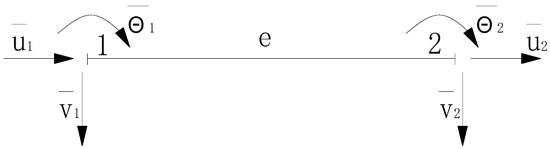
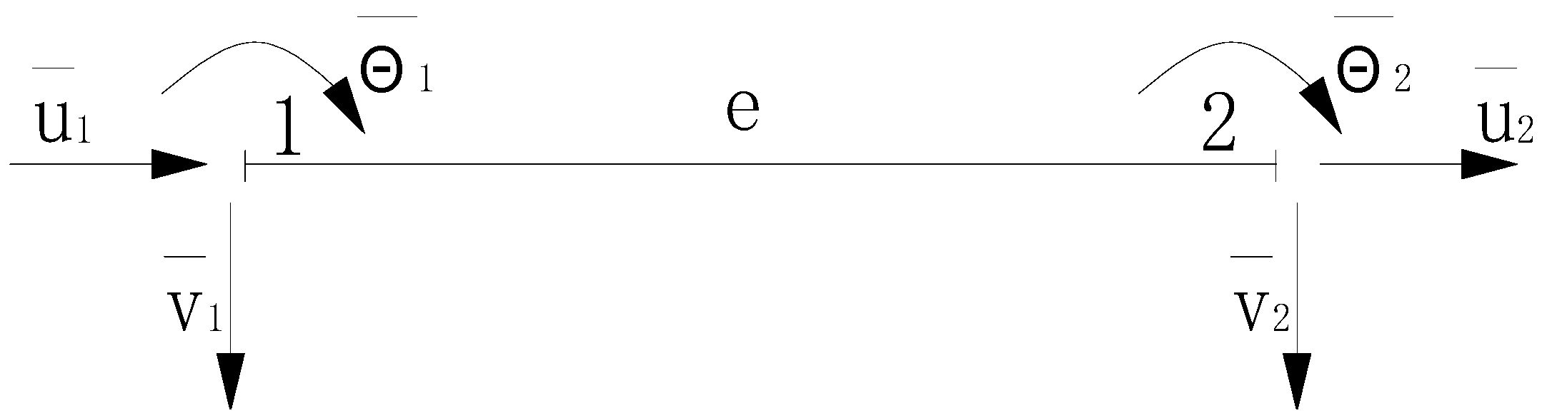
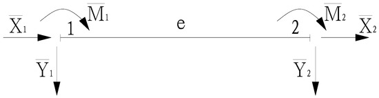
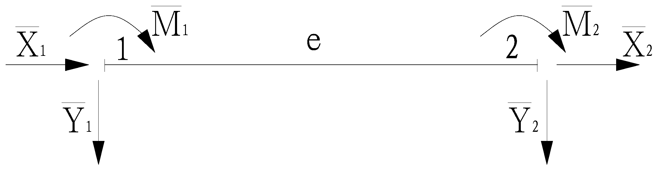
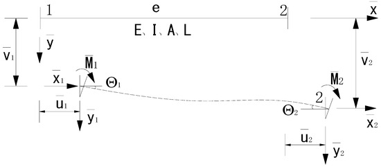
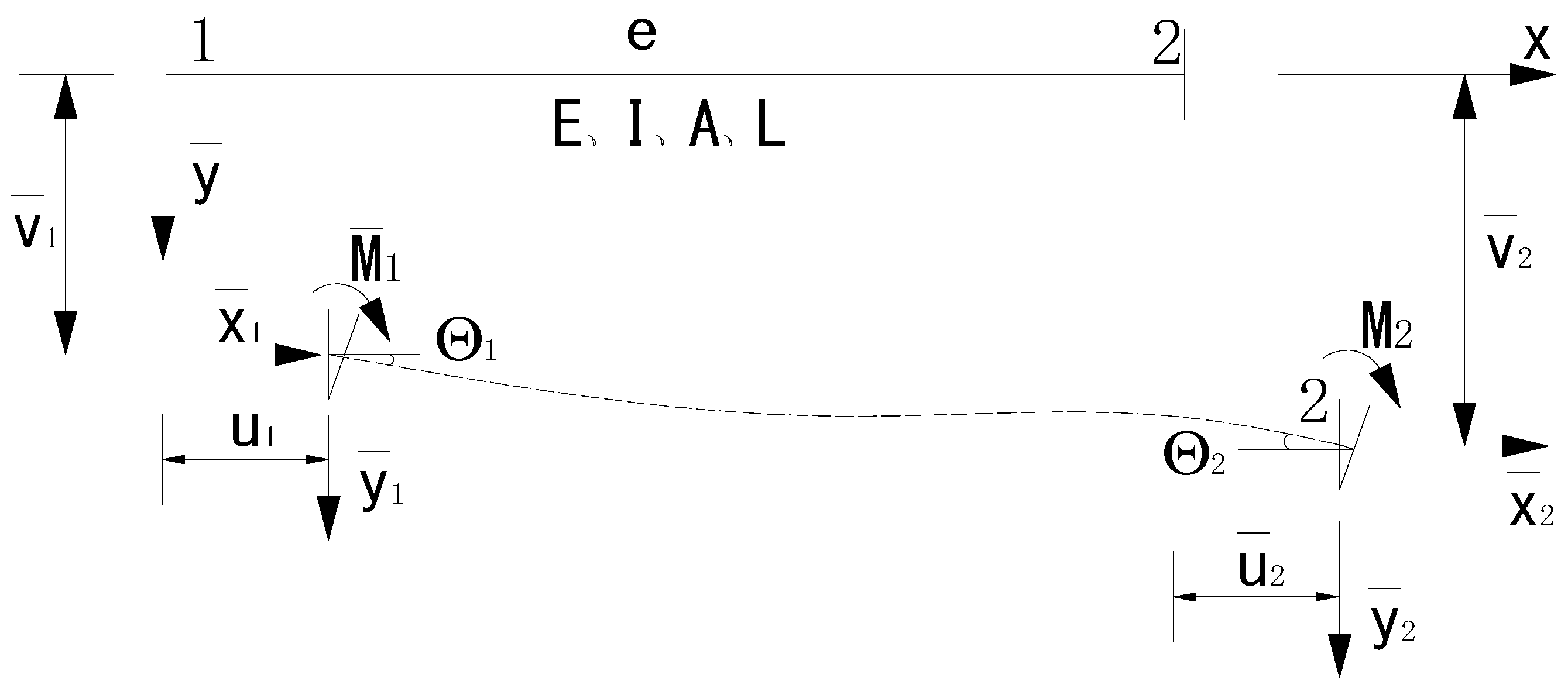
Any member of the wood truss connected by tooth plates is denoted as element e. The displacements and end forces at the two ends of element e are shown in Figure 1 and Figure 2, respectively. Thus, we can derive the element end displacement vector and element end force vector in the local coordinate system.
Figure 1.
Rod End Displacement.
Figure 2.
Rod end internal forces.
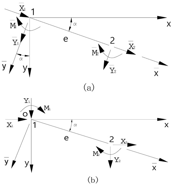
In order to establish a numerical calculation relationship between the element end displacement vector and the element end force vector , it is also necessary to analyze the stiffness matrix of the wood truss member element. As shown in Figure 3, the elastic modulus, section moment of inertia, cross-sectional area and length of the member element are denoted as E, I, A, and , respectively.
Figure 3.
General rod element.
Given the fixed material and cross-section of each wood truss member, the stiffness matrix of the member element can be determined based on the member’s elastic modulus E, moment of inertia of the cross-section I, cross-sectional area A, and length . Thus, the calculation derived in Equation (1) describes the relationship between the element end displacement vector and the element end force vector in the local coordinate system.
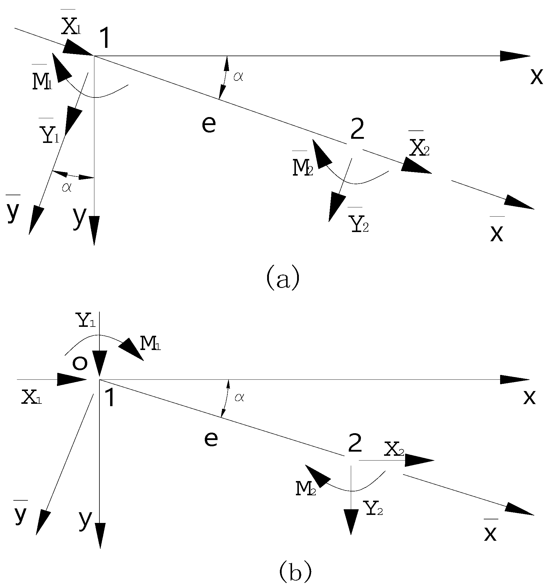
As shown in Figure 4, for element ‘e’, its local coordinate system is denoted as , and the global coordinate system as , the angle θ from the x-axis to the axis is defined as positive when measured clockwise.
Figure 4.
Transformation relationship of element nodal forces. (a) Element nodal forces in the local coordinate system; (b) element nodal forces in the global coordinate system.
Based on the basic principles of structural mechanics, the element end forces shown in Figure 4 are used to obtain the transformation relationships between the element end forces and end displacements in the two coordinate systems by introducing the element coordinate transformation matrix , as expressed in Equations (2) and (3).
By substituting Equations (2) and (3) into Equation (1), we obtain:
Premultiplying both sides of the equation by yields:
Element stiffness matrix in the global coordinate system .
2.2. Element Assembly of Truss Structures
Two numbering systems are employed during element assembly: Global numbering—a unified numbering scheme for the entire structure, where nodes are sequentially numbered according to their displacement degrees of freedom for global analysis—and local numbering—the numbering system used for individual element analysis.
Let denote the structural displacement vector and represent the structural load vector. The global equilibrium equation is expressed as follows:
The global stiffness matrix is constructed by expanding the element stiffness matrices in the global coordinate system through the finite element assembly procedure. Before assembly, the relationship between local and global numbering of nodal displacement components must be established. For each element, the vector composed of global displacement numbers is termed the “element location vector”, denoted as . The mapping between local and global numbering is established through the element location vector. The assembly process involves: Replacing row (i) and column (j) in the element stiffness matrix with new indices , from the element contribution matrix, and systematically superimposing all element contribution matrices to form the global stiffness matrix .
2.3. Calculation of Joint Displacements and Internal Forces of Planar Trusses
Solving the structural matrix equation yields the nodal displacements and internal forces in the global coordinate system. Through coordinate transformation, the nodal displacements and member-end forces in the local coordinate system of each element can then be determined.
The axial force calculation equation for planar trusses is given as follows:
2.4. Calculation of Support Reactions for Planar Trusses
Nodal internal forces of elements in the global coordinate system :
In the equation, and represent the nodal internal forces at the starting and ending nodes of the element, respectively. The support reaction equals the sum of nodal internal forces from all connecting elements minus the applied nodal load at that support. Let denote the reaction force at the k-th nodal support, and then:
In the equation, m represents the number of elements connected to support node k, and denotes the nodal load applied at support k.
2.5. Design of Calculation Program for Truss with Tooth-Plate Connections
Based on the above calculation principles, the calculation of internal forces, slip displacements, and deflection of wood trusses connected by tooth plates has been implemented using Fortran 90. During the program’s calculation process, the truss members are categorized into two types: truss members and beam-like members. Truss members primarily include web members, as well as additional virtual web members added at end nodes, while beam-like members mainly consist of top and bottom chords, including those at end nodes that simulate tooth-plate connections. For truss members, only displacements along and perpendicular to the member axis are calculated, and the internal forces require only axial force computation. For beam-like members, displacements and rotations at member ends are calculated, and the internal forces include axial force, shear force, and bending moment.
The program incorporates the anti-slip stiffness of simulated members at tooth-plate connection nodes to compute the slip deformation at these nodes. Previous studies on the load–slip behavior of tooth-plate connections, based on experimental investigations, have established the relationship between load and slip [22] as follows (test materials used domestic Chinese fir, commonly employed in timber structures in China, with wood strength class TC11, Grade A specified in GB 50005—2017 Code for Design of Timber Structures; Ordinary Q235 steel tooth plates of 1.5 mm thickness, including types TR50 and TR75, with a tooth density of 25 teeth per 100 mm2 and a tooth penetration depth into wood of 15 mm). The test was conducted under static loading, without considering the effects of dynamic or cyclic loads, and is therefore applicable to mechanical analysis under static load conditions:
In the equation, A represents the effective bearing area of the tooth plate, and s denotes the relative slip displacement at the joint (mm).
According to the code requirements, the determination method for the slip capacity of toothed plates is as follows: When a relative slip of 0.8 mm occurs at a single toothed-plate connection joint in a timber truss, this value is taken as the controlling limit state for the slip bearing capacity of the truss. Therefore, in the program calculations, the tensile stiffness of the virtual member used to simulate the slip effect can be determined using the formula from the first stage (elastic stage) in Equation (11). Meanwhile, through an analysis of the constitutive relationship between load and slip, it is found that when the slip of the joint is limited as specified by the code and the load on the member is constant, the area of the toothed plate becomes the core parameter affecting the slip performance of the structure, given that plates with the same configuration are used.
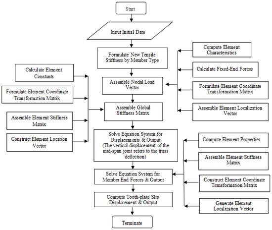
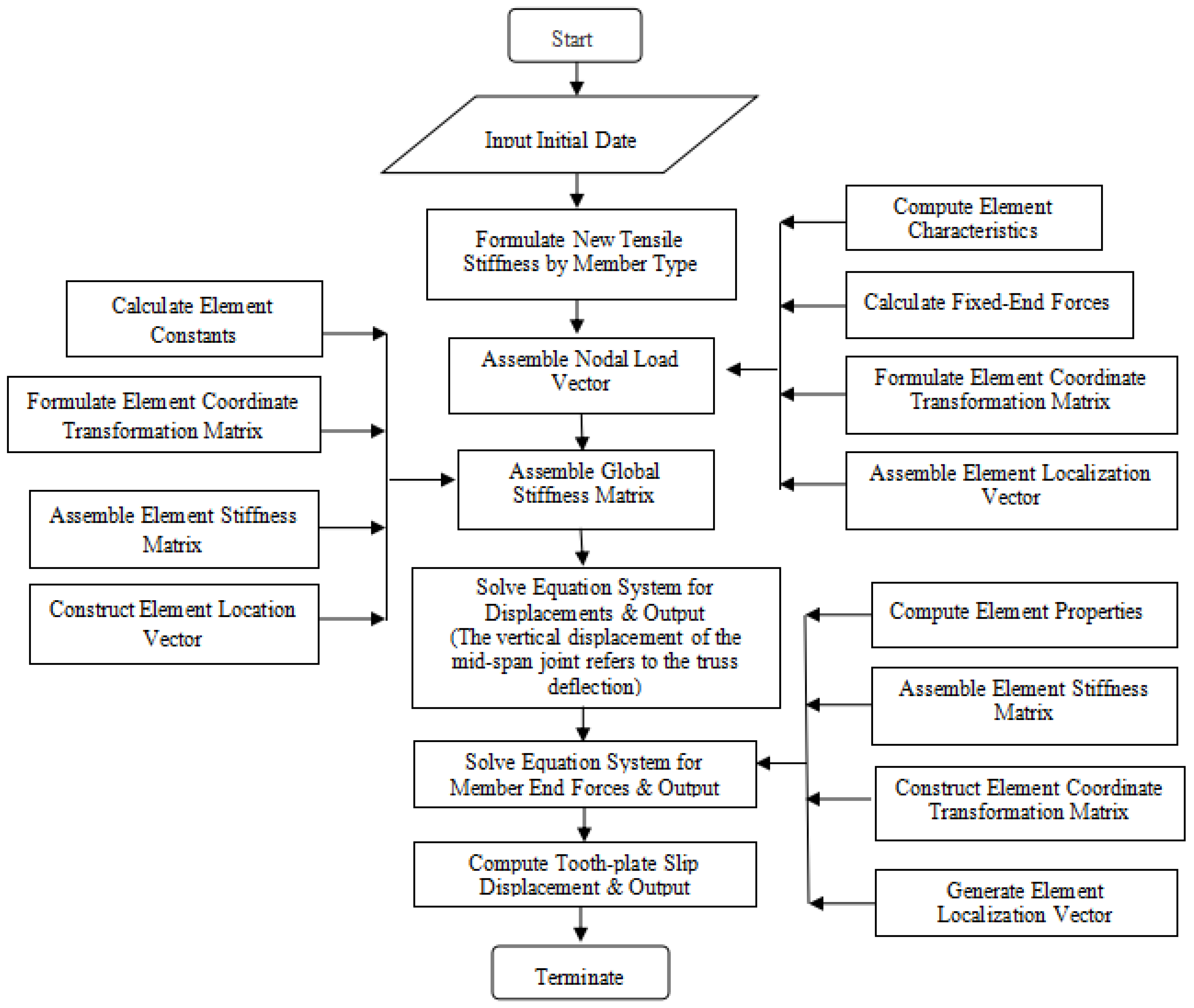
The computational flowchart is illustrated in Figure 5.
Figure 5.
Flowchart of calculation program for internal forces and slip in timber trusses with tooth-plate connections.
The entire self-developed program adopts an architecture of “main program coordination + subprogram division of labor,” where the main program serves as the core control unit responsible for overall process scheduling and subprogram invocation. The ten subprograms are as follows: Subroutine 1 for inputting data; Subroutine 2 for reading dialog box data; Subroutine 3 for outputting intermediate model data; Subroutine 4 for calculating internal forces and slip; Subroutine 5 for determining element positioning vectors; Subroutine 6 for calculating element constants; Subroutine 7 for forming the element stiffness matrix; Subroutine 8 for forming the element coordinate transformation matrix; Subroutine 9 for calculating element fixed-end forces; and Subroutine 10 for outputting result data. During program calculation, Subroutine 4, as the core computational module, sequentially calls Subroutines 5, 6, 7, 8, and 9. Finally, the calculation results are output through a separate module by invoking Subroutine 10 via the main program. The parameters required for program calculation include the following: (1) basic parameters—number of elements ne, number of joints nj, number of joint displacements n, half bandwidth nw, number of joint loads npj, and number of non-joint loads npf; (2) element parameters—joint coordinate arrays x(nj) and y(nj), array of unknown joint displacements jn(3,nj), element end joint numbering array je(2,ne), element tensile stiffness array ea(ne), and element flexural stiffness array ei(ne); and (3) load parameters—structure array pj(npj) containing the displacement component numbers and values of joint loads, and structure array pf(npf) containing the element numbers, load type codes, position parameters, and values of non-joint loads. The calculable output results include the internal forces (axial force, shear force, bending moment) of each member, the displacements (X-direction displacement, Y-direction displacement, rotation angle) of each joint, and the joint slip. This program features clear overall logic and a high degree of modularization, facilitating engineering applications and future modifications.
As can be seen from the program flowchart, this calculation method can not only accurately calculate the internal forces of each joint and member of wood trusses connected by tooth plates, but also obtain the solutions to the truss deflection and the slip displacement of each tooth-plate connection joint, thus providing computational support for the subsequent multi-objective optimization method for tooth-plate design.
3. Analysis of Computational Models
3.1. Test Specimens and Loading Conditions
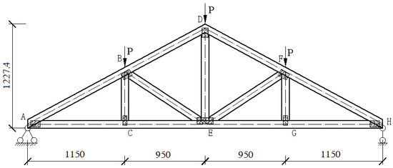
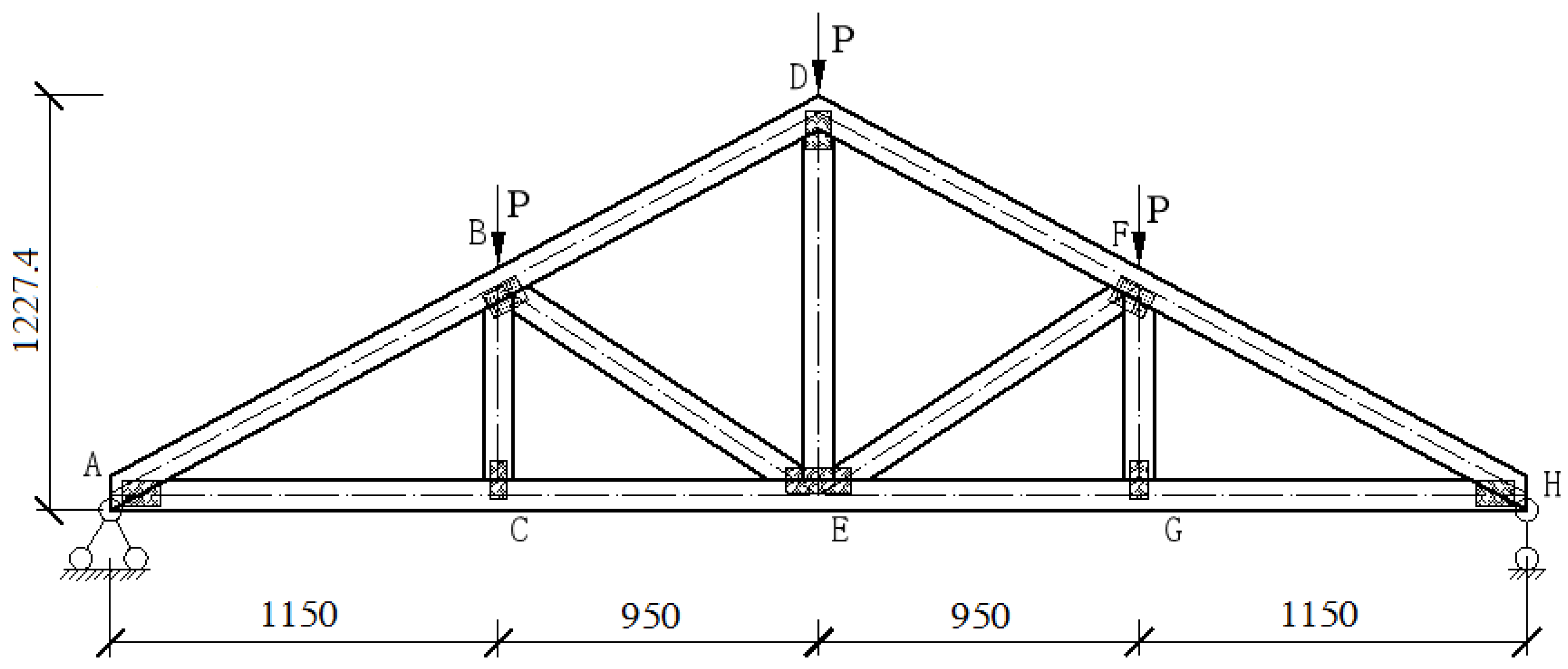
The present study examines a 4.20 m span lightweight timber truss system with tooth-plate connections. All structural members employ domestically sourced Chinese fir (Cunninghamia lanceolata), conforming to Strength Class TC11 (Group A) as stipulated in GB50005-2017 Code for Design of Timber Structures. The members feature uniform dimensional lumber sections of 38 mm (width) × 89 mm (depth), with geometric configuration detailed in Figure 6. Material mechanical properties strictly adhere to the parameters prescribed in GB50005-2017. The specifications of the tooth plates are consistent with those used in the slip test, employing 1.5 mm thick ordinary Q235 steel plates of types TR50 and TR75, both with a tooth density of 25 teeth/100 mm2 and a tooth penetration depth of 15 mm into the wood. The technical specifications and principal orientation of tooth-plate connectors at each nodal joint are systematically cataloged in Table 1.
Figure 6.
Howe-type timber truss with metal tooth-plate connections. All dimensions are in millimeters. The letters in the figure represent the tooth-plate numbers.
Table 1.
Specifications and principal axis orientation parameters of tooth plates.
The loading regime is established based on actual engineering requirements. The permanent loads consist of roof tiles (0.6 kN/m2) and OSB sheathing and truss self-weight (0.4 kN/m2), yielding a total dead load of 1.0 kN/m2. According to design specifications, a variable load of 0.5 kN/m2 was adopted for non-accessible roofs. Load Combination: With a truss spacing of 1400 mm, the characteristic line loads per truss are dead load, 1.4 kN/m (1.0 × 1.4) and live load, 0.7 kN/m (0.5 × 1.4). The design load combination 1.3G + 1.5Q results in 2.87 kN/m. Nodal loads were calculated through equivalent distribution, with a design nodal load of 4.0 kN (2.87 × 4.2/3). To satisfy structural reliability analysis requirements [23], all subsequent computational examples apply 4.00 kN concentrated combined loads at nodes B, C, and D along the top chord to simulate experimental loading conditions.
3.2. Computational Model Formulation
3.2.1. Benchmark Model Based on Canadian TPIC Specifications
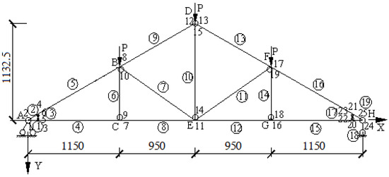
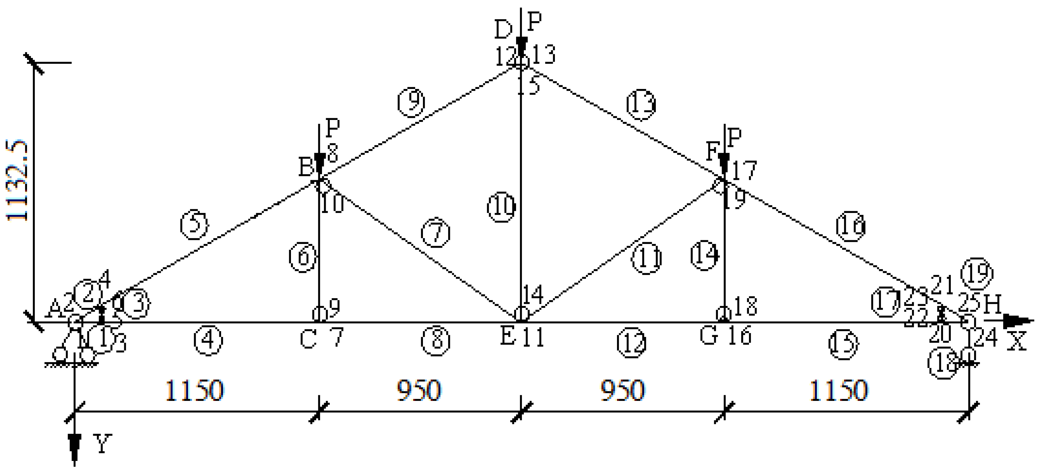
This model (hereinafter referred to as Model 1) adopts the calculation method specified in the Canadian TPIC standard, without considering the influence of tooth-plate slip, and only accounts for the axial stiffness and flexural stiffness of the members. As shown in Figure 7, the top and bottom chord members are simulated using beam elements, accounting for their bending resistance, while the web members are simulated using pin-ended truss elements, transmitting axial forces only [24]. Through this model, the internal force distribution of the members and nodal displacements can be calculated, serving as a comparative benchmark for subsequent models that consider tooth-plate slip.
Figure 7.
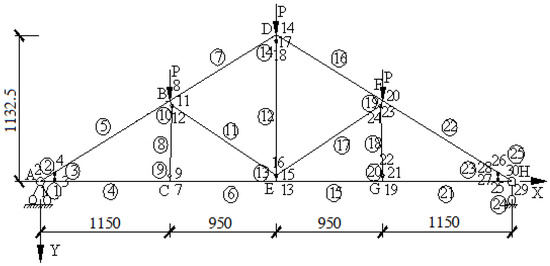
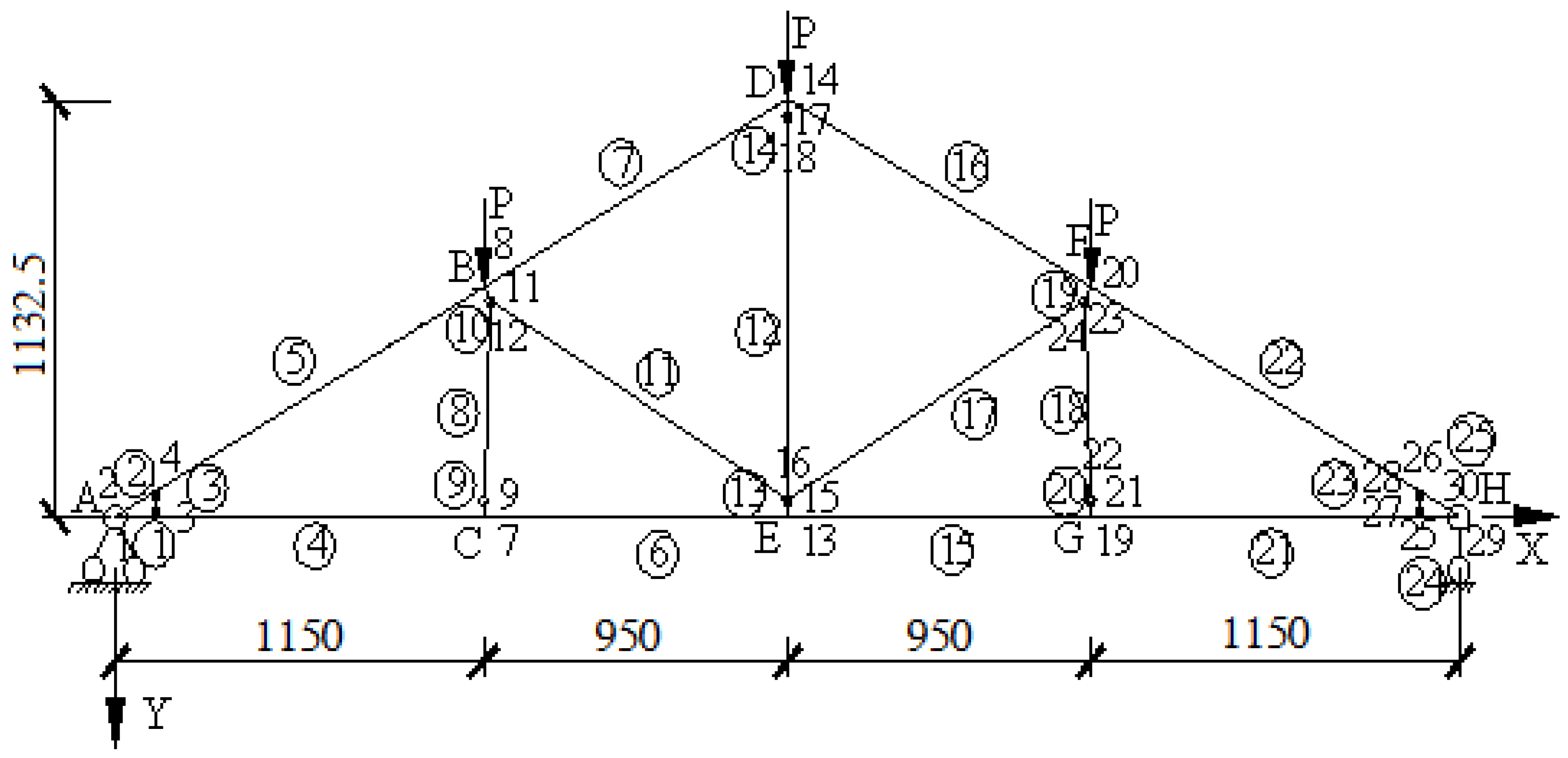
Node numbering and element numbering of Model 1. All dimensions are in millimeters. The letters in the figure represent the tooth-plate numbers, the non-circled numbers represent node numbers, and the circled numbers represent element member numbers. The meanings are the same in Figures 8 and 14.
3.2.2. Simulation of Slip Effects Using Virtual Members with Actual Dimensions
To accurately account for the slip characteristics of tooth-plate connections, virtual members with actual lengths are employed for simulation [25,26]. The core mechanical significance of this modeling assumption is to achieve the equivalent simplified characterization of the semi-rigid-slip behavior of tooth-plate connections. Essentially, the slip of tooth-plate connections arises from the shear deformation at the interface between the tooth-plate teeth and the wood, as well as the relative displacement after the teeth embed into the wood. By assigning actual dimensions to the virtual members, their mechanical behaviors are modeled to correspond with those of physical entities. The length and cross-sectional dimensions of these virtual members are directly related to the moment arm effect and bearing area during the slip process, thus avoiding the disconnection between the mechanical responses of virtual elements and the actual structure. From the perspective of the force transfer path, the virtual members undertake the transitional force transmission between the tooth plates and the truss members, converting the dispersed contact forces of the teeth into concentrated element forces. This effectively simulates the influence of contact stiffness degradation on the mechanical properties of the overall truss during the slip process. This mechanical concept is consistent with the approach adopted by Zhu Runxiang et al. in their research on mortise and tenon joints, where virtual spring elements were used to represent semi-rigid properties. Both methods realize the simplified equivalence of complex connection behaviors through virtual elements. The specific modeling approach is as follows:
- (1)
- Structural Member Treatment: The upper and lower chords are simulated using beam elements, accounting for bending deformation. The web members are simulated using truss elements that only resist axial forces, with pinned connections at both ends.
- (2)
- Nodal Connection Treatment: At the intersection point of the web member and the chord member axis, a perpendicular line is drawn normal to the chord. The intersection point of the perpendicular line with the inner side of the chord is designated as the theoretical pinned joint. A virtual member is added between the perpendicular point and the pinned joint. The virtual member is rigidly connected to the chord. The virtual member and the web member are connected via pinned joints.
- (3)
- Based on the relationship between the force and slip of the tooth-plate connection, as shown in Equation (11), the equivalent tensile stiffness of the virtual member can be derived as follows:
That is, the axial stiffness of the virtual member is calculated according to Equation (12):
In Equation (12):
Ac: Effective bearing area of the tooth plate;
: Cross-sectional area of the chord member adjacent to the virtual member;
E: Elastic modulus of the chord member adjacent to the virtual member;
l: Equivalent length of the virtual member.
- (4)
- The specific configuration of this computational model (hereinafter referred to as Model 2) is illustrated in Figure 8:Figure 8. Node and element numbering of Model 2. All dimensions are in millimeters.
Using the proposed model, inputting the relevant parameters into the computational program allows for the determination of internal force distribution, deformation behavior, and slip displacements at the tooth-plate joints in the timber truss.
3.2.3. Virtual Truss Model for Composite Structure Tooth-Plate Joints
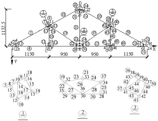
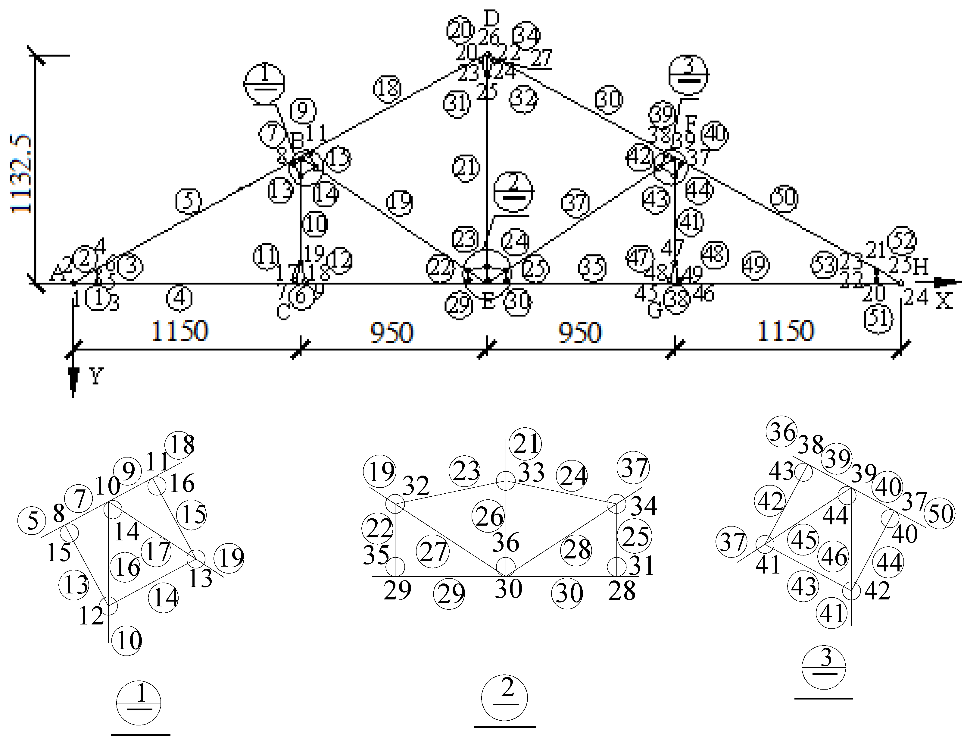
The slip of tooth-plate connections does not occur as a uniform displacement in a single direction; rather, it is a complex process involving local compression, friction between the teeth and the wood, and the synergistic load-bearing action of multiple teeth. Through the topological arrangement of multiple elements and nodes, the virtual micro-truss can capture the slip differences and stress distribution characteristics in different regions of the tooth plate. The stiffness division of labor of virtual micro-truss elements (lateral anti-slip and longitudinal anti-embedment) is consistent with the force mechanism of tooth-plate connections: lateral elements simulate the frictional slip resistance at the interface between the teeth and wood, while longitudinal elements restrain the excessive embedment deformation of the teeth. The coupling effect of the multi-tooth force bearing is reflected through the deformation compatibility between elements, which is consistent with the mechanical concept of simulating the interaction of stress fields through discrete elements in multi-pin connections. Such assumptions are also adopted in the calculation and processing of metal-plate-connected wood truss joints by the commercial software ABAQUS [27]. This model (hereinafter referred to as Model 3) simulates the complex stress state at tooth-plate connections by establishing a virtual micro-truss, while considering slip effects through equivalent tensile stiffness. The specific modeling assumptions are as follows:
- (1)
- Node Positioning and Connection Methods: Determine the positioning and connection methods of end nodes in accordance with the provisions of the TPIC specification; the anti-tensile slip stiffness of the top and bottom chords adopts actual values; the bending stiffness is determined based on actual cross-sectional dimensions; and the tensile stiffness of web members (38 mm × 89 mm) is also simulated using actual calculated values.
- (2)
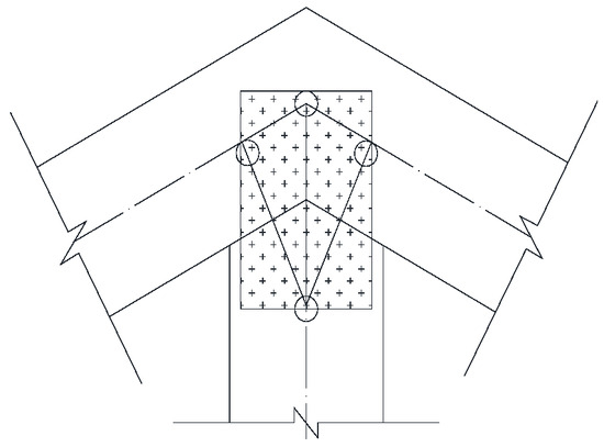
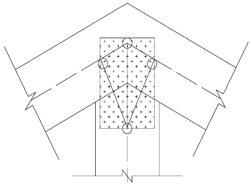
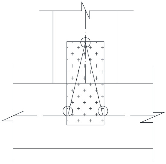
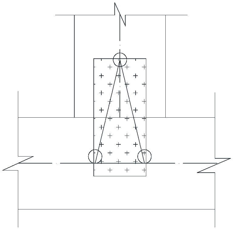
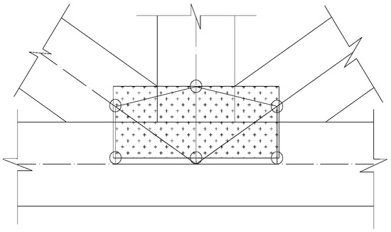
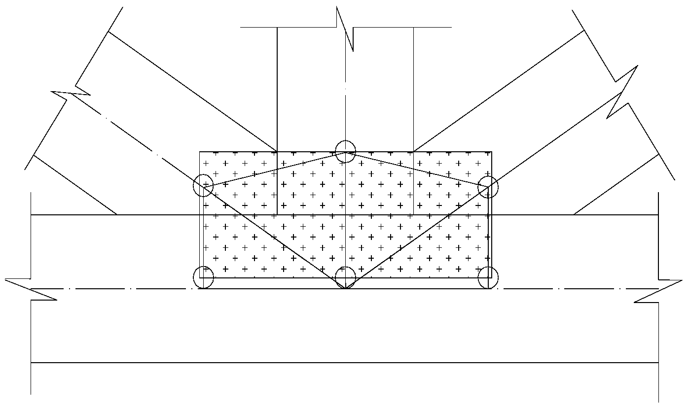
- Ridge Node Processing (as shown in Figure 9): A perpendicular line is drawn through the ridge point to intersect with the centerline of the chord, thereby determining the first sub-node; when the two intersection points do not coincide, the midpoint is taken as the first sub-node; other sub-nodes are determined based on the intersection points of the outermost tooth line of the toothed plate with the centerlines of the web member and chord; the sub-nodes are connected to form the truss of the ridge node; and the chord remains continuous, while other simulated members are pin-connected at both ends.Figure 9. Ridge joint diagram.
- (3)
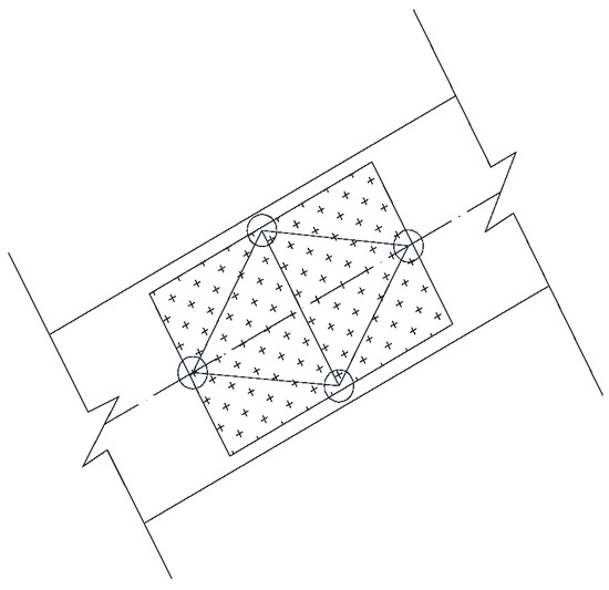
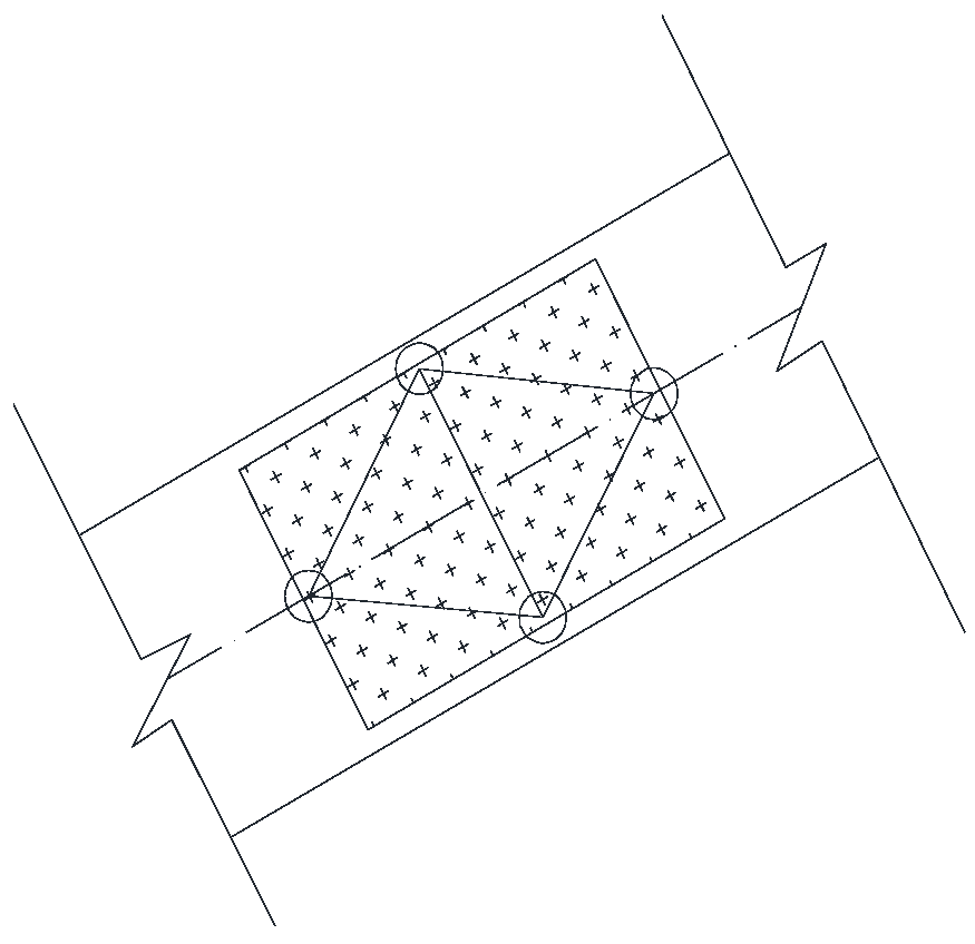
- Splice Joint Processing (as shown in Figure 10): The intersection points of the joint line and the outermost tooth line of the toothed plate are taken as the first and second sub-nodes. The intersection points of the member centerline and the outermost tooth line of the toothed plate are taken as the third and fourth sub-nodes. These sub-nodes are connected to form the truss of the splice joint, with all simulated members modeled as pin-connected at both ends.Figure 10. Butt joint diagram.
- (4)
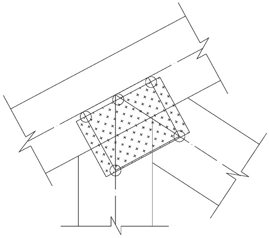
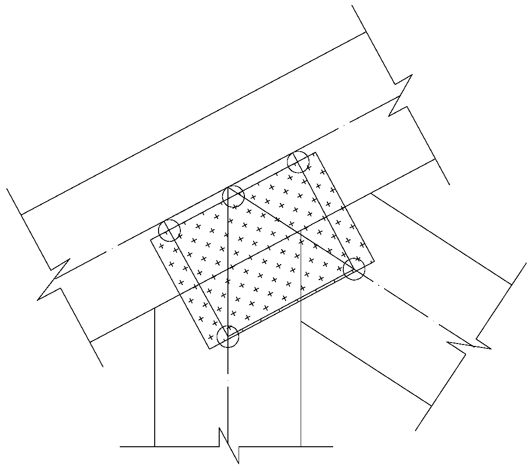
- Web Member Joint Processing (as shown in Figure 11, Figure 12 and Figure 13): The midpoint of the contact surface and the perpendicular foot of the chord centerline are taken as the first sub-node. The intersection points of the outermost tooth line (or its extension) of the toothed plate and the member centerline are taken as the remaining sub-nodes. These sub-nodes are connected to form the web member truss, with the chord remaining continuous and all other members modeled as pin-connected at both ends.Figure 11. Schematic of a web member connected to a chord member.Figure 12. Schematic of two web members connected to a chord member.Figure 13. Schematic of three web members connected to a chord member.
- (5)
- Modeling Sequence: Prioritize establishing the ridge joint truss; sequentially construct web member joint trusses (ordered by the number of intersecting members from most to least); finally, process other joints.
- (6)
- Stiffness Assignment Principle: For members located at the original chord positions in ridge and web member joints, employ actual tensile and flexural stiffness; other simulated members consider only slip stiffness (pinned at both ends, neglecting flexural stiffness).
Inputting the relevant model parameters into the analysis program yields the timber truss’s internal force distribution, deformation behavior, and tooth-plate slip displacement.
The comprehensive computational model is depicted in Figure 14.
Figure 14.
Node and element numbering scheme for Model 3. All dimensions are in millimeters.
3.2.4. Model Support and Loading
Based on the model assumptions described previously, all three models are simply supported at both ends of the bottom chord of the truss. Models 1 and 2 were subjected to a single static loading analysis with a vertically downward force of 4.0 kN applied at joints B, D, and F, with the calculation results presented in Table A1 and Table A2. Model 3 underwent three separate static loading analyses with vertically downward forces of 4.0 kN, 4.42 kN, and 5.62 kN applied at joints B, D, and F; the calculation results for the 4 kN loading are detailed in Table A3, while the main results for the other loading cases are presented in the comparative analysis.
4. Comparative Analysis
To validate the accuracy of calculations performed by the self-developed program, a static analysis of a single timber truss with identical member dimensions was conducted using the general-purpose finite element software ABAQUS (2022 version). The truss was subjected to loading at three upper joints, with the characteristic values of permanent load and live load being 1.95 kN and 0.98 kN, respectively. The load combination factors were taken as 1.3 for permanent load and 1.5 for live load, resulting in a design load of 1.95 × 1.3 + 0.98 × 1.5 = 4.0 kN, which is consistent with the loading magnitude applied to the models detailed in Table A1, Table A2 and Table A3. The main control parameters adopted in the calculation are presented in Table 2.
Table 2.
Main control parameters for ABAQUS calculation.
The comparison of the main internal forces, deflections, and tooth-plate slip results calculated by ABAQUS with those from Models 1 to 3 is presented in Table 3.
Table 3.
Comparison of maximum internal forces, deflections, and slip between ABAQUS and Models 1–3 under the same loading conditions.
Comparing the calculation results in Table 3, it is found that for Model 1 versus the ABAQUS results, the difference rates are 2.4% for the maximum axial force in the chords, −45.1% for the maximum bending moment in the chords, 26.0% for the maximum axial force in the web members, and −46.8% for the deflection. For Model 2, the difference rates compared to ABAQUS are −0.3% for the maximum axial force in the chords, −12.0% for the maximum bending moment in the chords, 3.2% for the maximum axial force in the web members, −8.1% for the deflection, and −13.0% for the maximum tooth-plate slip. For Model 3, the difference rates relative to ABAQUS are −0.1% for the maximum axial force in the chords, −2.1% for the maximum bending moment in the chords, 1.0% for the maximum axial force in the web members, −3.2% for the deflection, and −5.2% for the maximum tooth-plate slip. This comparative analysis indicates that the results from Model 3 are largely consistent with those from the general-purpose finite element software, with the maximum slip discrepancy being approximately −5%, and the internal forces and deflection values showing good agreement. This demonstrates the practicality and accuracy of the calculation program developed in this study.
A comparative analysis of Model 1 with the other two models that account for slip effects (detailed results are provided in Table A1, Table A2 and Table A3) indicates that both Model 2 and Model 3, which consider slip, can effectively reflect the influence of tooth-plate slip on the mechanical behavior of the timber truss. Compared to Model 1, the axial forces in all members are reduced, while the bending moments and shear forces increase to varying degrees. Model 1 has 25 joints and 19 elements; Model 2 has 29 joints and 25 elements; Model 3 has 49 joints and 53 elements. In terms of computational efficiency, Model 1 is the highest, but it cannot analyze structural slip. Although the computational time cost of Model 3 is indeed higher than that of Model 2, given the data processing speed of modern computers, the computational efficiency of Model 3 is still much higher than that of current general-purpose finite element software for typical light-frame timber truss structures with tooth-plate connections, making it suitable for the practical design and application of timber trusses with tooth-plate connections. Therefore, the following analysis primarily compares the calculation results of Model 1 and Model 3 to assess the impact of the slip effect on internal forces.
4.1. Influence of Tooth-Plate Slip on Member Internal Forces
A comparison of calculation results under identical loading conditions (4 kN vertical loads applied at nodes B, D, and F) reveals the following:
- (1)
- Axial Force Variation: The maximum axial force in the top chord decreases from 12.319 kN (Model 1) to 12.154 kN (Model 3), while the axial force in the bottom chord reduces from 10.857 kN to 10.608 kN. The distribution of axial forces in web members becomes more uniform, with the maximum axial force decreasing from 4.209 kN to 3.616 kN.
- (2)
- Bending Moment and Shear Force Variation: The maximum bending moment in the top chord increases from −0.101 kN·m to −0.162 kN·m, and that in the bottom chord rises from −0.085 kN·m to −0.132 kN·m. Shear forces generally increase, though they remain secondary to axial forces in magnitude.
Theoretical analysis shows that the slip effect amplifies structural deformation, resulting in a more uniform axial force distribution. At the same time, since the flexural rigidity of the members remains unchanged, bending moments and shear forces increase correspondingly. The main internal force of each member in wood trusses connected by tooth plates is axial. When tooth-plate slip is not considered, the calculated axial force is on the high side, and the calculated internal force is on the safe side.
4.2. Influence of Tooth-Plate Slip on Structural Deformation
The mid-span deflection increases from 3.3 mm (Model 1) to 6.0 mm (Model 3), representing an 82% increase, while the horizontal displacement at the right end of the truss rises from 1.5 mm to 2.7 mm, an 80% increase. After accounting for tooth-plate slip, both vertical deflections and horizontal displacements exhibit significant amplification, which aligns with the ABAQUS calculation results. This demonstrates that neglecting slip effects in truss deformation calculations leads to unconservative (less safe) results.
4.3. Multi-Objective Optimization Analysis of Tooth-Plate Design
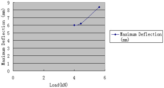
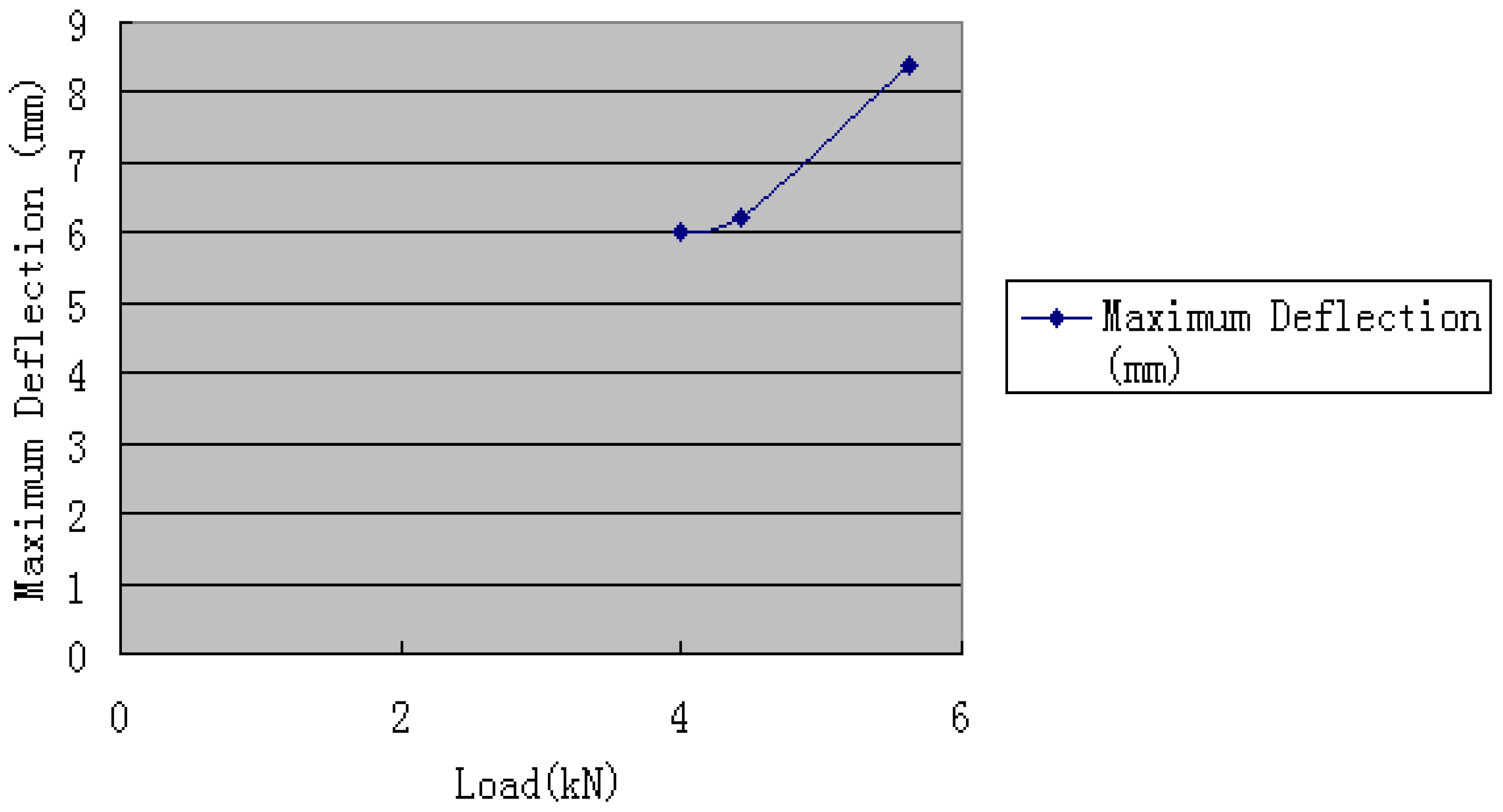
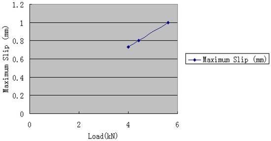
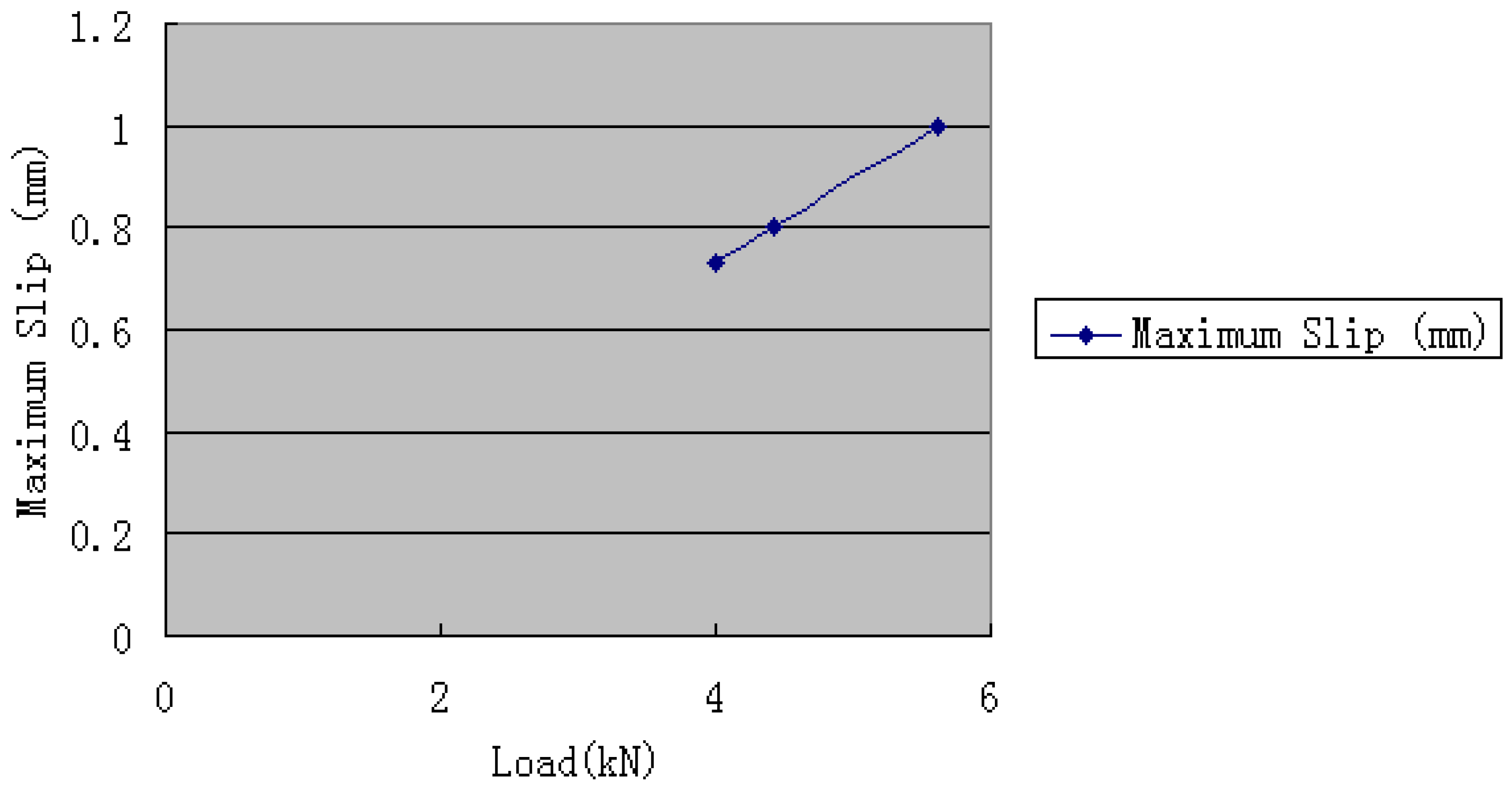
Based on the calculation and analysis presented earlier in this paper, the internal forces of each truss member, the overall truss deflection, and the slip displacement of each tooth-plate connection joint are simultaneously obtained via program calculation, which provides important data support for the multi-objective optimization design of tooth plates. Taking Model 3 in this paper as an example, when the tooth-plate slip displacement reaches the specification limit of 0.8 mm, the load increases to 4.42 kN, the mid-span deflection is 6.2 mm (less than the specification limit of 8.4 mm), and the axial force of the bottom chord is 11.72 kN (meeting the bearing capacity requirements); when the deflection reaches the specification limit of 8.4 mm, the load at each joint needs to be increased to 5.62 kN, the slip displacement reaches 1.0 mm, and the axial force of the bottom chord attains 14.90 kN. The relationships between the maximum deflection and maximum slip corresponding to different joint loads are detailed in Figure 15 and Figure 16. Based on these calculations, the area of the tooth plates in this truss can be slightly reduced to ensure that both tooth-plate slip and mid-span deflection simultaneously satisfy the specification limits. Furthermore, by adjusting the cross-sectional dimensions of the members, it is possible to have the tooth-plate slip, mid-span deflection, and member load-bearing capacity all meet the code requirements concurrently, thereby achieving an economically efficient design. In engineering practice, this calculation program enables the simultaneous analysis of the three key design factors—member capacity, tooth-plate slip, and mid-span deflection—for timber trusses, facilitating the optimization of tooth-plate area and member cross-sections to achieve the optimal design objective of safety and economy. Thus, the multi-objective control of bearing capacity, slip, deflection and material consumption is realized.
Figure 15.
Joint load–deflection relationship diagram.
Figure 16.
Joint load–maximum slip relationship diagram.
The analysis indicates that the specification-specified slip limit of 0.8 mm has a reasonable safety margin, which can not only ensure structural safety but also give full play to material performance. In practical design, coordinated design of components and joints can be carried out in accordance with the specification requirements for tooth-plate slip displacement, mid-span deflection and member bearing capacity, so as to achieve the design objectives of safety, applicability and economy. The calculation program in this paper realizes the simultaneous calculation of internal forces of members, tooth-plate slips displacement and deflection of wood trusses connected by tooth plates, but it fails to perform multi-round regression calculations of tooth-plate area to automatically generate the calculation of optimal tooth-plate consumption. Meanwhile, although the tree species and tooth-plate type adopted in this study are common materials for domestic light timber structures, due to the limitations of this research, no extensive tests and analyses have been conducted on other materials. Therefore, it is necessary to conduct discriminative analysis when there are differences in the materials used for specific applications.
4.4. Application Analysis
In terms of conventional design workflow, this method can be applied in the initial stage of the structural design of timber trusses with tooth-plate connections, serving as a supplementary tool to current simplified design approaches. After preliminarily determining member cross-sections and joint configurations, designers can use this program to conduct specialized analyses of the slip effect in critical joint regions, evaluate its influence on the overall internal force distribution and deformation of the structure, and subsequently optimize joint detailing and tooth-plate layout. This enables a closed-loop design process of “calculation–analysis–optimization.”
In terms of software implementation and compatibility, although the current program is developed on the Fortran90 platform, its core algorithm is highly consistent with the solution principles of mainstream finite element software (such as PKPM-CAE and ABAQUS). By incorporating the constitutive equation for tooth-plate slip into a user-defined material subroutine, the program can achieve seamless integration with commercial software, facilitating direct utilization by engineering designers.
In terms of alignment with current codes, this method is fully compatible with the verification requirements for the ultimate limit state and serviceability limit state specified in China’s Standard for Design of Timber Structures (GB 50005) and Technical Specification for Light-Frame Timber Trusses (JGJ/T 265). The internal forces of members and joint slip values obtained from calculations can be directly used for the load-bearing capacity verification and deflection limit checks required by the codes, while also providing theoretical references and data support for future code revisions.
5. Conclusions and Prospects
In summary, through a systematic analysis of timber trusses with tooth-plate connections, this paper reveals the core mechanisms influencing the mechanical performance of such connections, validates the rationality of current codes, and proposes an optimization design strategy that balances safety and economy. The specific conclusions are as follows:
- (1)
- Influence patterns of key parameters: The study found that when the tooth density and tooth height of the plate are fixed, the area of the tooth plate becomes the core parameter affecting structural performance, as it is directly correlated with and governs the tooth-plate slip, the design value of joint load-bearing capacity, and the final deflection of the truss.
- (2)
- Validation of the rationality of current codes: The analysis confirms that, on the premise that members meet the ultimate load-bearing capacity requirements, the tooth-plate area determined based on the slip limit of the connections naturally satisfies the code’s control standards for truss deflection.
- (3)
- Optimization strategy for economical design: To achieve economical material usage, it is recommended to balance the following three factors during design—the joint slip limit, member load-bearing capacity, and the deflection limit. On the basis of ensuring load-bearing capacity, the slip limit can be appropriately relaxed to achieve coordination with deflection control requirements, thereby identifying a more economical tooth-plate configuration. Through the computational program developed in this study, the calculation and comparison of these three factors for multiple design scenarios can be efficiently performed, offering reliable practical engineering value. Moreover, this multi-objective optimization approach balances structural safety with material utilization efficiency.
Future research can be explored in the following two aspects:
- (1)
- Expanded parametric studies: To investigate the universal patterns governing the relationship between internal forces and slip in trusses under different material combinations, various tooth-plate configurations (e.g., tooth density and tooth height), and multiple temperature conditions, thereby enhancing the applicability of the theoretical model.
- (2)
- Development of automated tools: Based on the above patterns, develop a computational program capable of performing multiple rounds of regression analysis. This program can comprehensively account for tooth-plate area, slip, deflection, and member internal forces, automatically iterating to determine the optimal material dimensions that satisfy code requirements, ultimately achieving the intelligent design objective of being “safe, applicable, economical, and rational.”
Author Contributions
Conceptualization, Q.L.; Methodology, Q.L.; Validation, R.L.; Formal Analysis, Q.L.; Investigation, R.L.; Resources, Q.L. and R.L.; Data Curation, G.L. and J.H.; Writing—Review and Editing, Q.L. and R.L. All authors have read and agreed to the published version of the manuscript.
Funding
This research was funded by the Scientific and Technological Innovation Team Construction Project of Nanjing Vocational Institute of Railway Technology (No. CXTD2023001), the Research Platform Project of Nanjing Vocational Institute of Railway Technology (No. KYPT2025003), and the High-Technology Direction Project of the Key Research and Development Science and Technology of Hainan Province, China (Grant No. ZDYF2024GXJS001).
Data Availability Statement
The original contributions presented in the study are included in the article, and further inquiries can be directed to the corresponding author.
Conflicts of Interest
The authors declare no conflicts of interest.
Appendix A
Table A1.
Calculation results of Model 1 under a load of 4 kN at joints B, D and F.
Table A2.
Calculation results of Model 2 under a load of 4 kN at joints B, D and F.
Table A3.
Calculation results of Model 3 under a load of 4 kN at joints B, D and F.
References
- Zhang, Z.Y.; Wang, S.Y.; Shen, Y.L.; Zhou, H.B. Experimental study on vertical vibration performance of long-span wood truss joist floors with metal plate connections. Build. Struct. 2024, 54, 121–128. [Google Scholar] [CrossRef]
- Xue, J.; Guo, R.; Xu, D. Shaking table test on 1/2-scale model of column-and-tie timber structure filled with wooden walls. J. Struct. Eng. 2020, 146, 04020281. [Google Scholar] [CrossRef] [Scilit]
- Yi, D.; Yuan, J.; Pan, Y. Full-scale seismic performance testing of a predamaged two-story traditional timber frame on a slope reinforced using viscoelastic dampers. J. Struct. Eng. 2024, 150, 04024025. [Google Scholar] [CrossRef] [Scilit]
- Shi, B.N.; Zhang, X.P. Size effects on anti-sliding capacity and tooth-bearing capacity of metal plate connections. China Wood Ind. 2015, 29, 27–29. [Google Scholar] [CrossRef]
- Song, L.L.; Wu, J.T.; Yang, H.F. Experimental study on the bearing capacity of bolted connections reinforced with metal plates in timber structures. Build. Struct. 2020, 50, 33–37. [Google Scholar]
- Wang, L.; Li, P.; Tang, X.; Zhang, D. Mechanical performance after high-temperature of metal-plate-connected joints in light wood structures. J. Constr. Steel Res. 2025, 227, 109313. [Google Scholar] [CrossRef] [Scilit]
- Izzi, M.; Polastri, A.; Fragiacomo, M. Modelling the mechanical behaviour of typical wall-to-floor connection systems for cross-laminated timber structures. Eng. Struct. 2018, 162, 270–282. [Google Scholar] [CrossRef] [Scilit]
- Pishro, A.A.; Tsavdaridis, K.D.; Liu, Y.; Zhang, S. Strengthening structural dynamics for upcoming Eurocode 8 seismic standards using physics-informed machine learning. Buildings 2025, 15, 3960. [Google Scholar] [CrossRef] [Scilit]
- GB 50005-2017; Standard for Design of Timber Structures. China Architecture & Building Press: Beijing, China, 2017.
- TPIC-2014; Canadian Standard for Design of Timber Trusses. Truss Plate Institute of Canada: Toronto, ON, Canada, 2014.
- ANSI/TPI 1-2022; American National Standard for Metal Plate Connected Wood Trusses. Truss Plate Institute: Madison, WI, USA, 2022.
- Aloisio, A.; Sejkot, P.; Pelliciari, M. Instability of compressed members in timber trusses assembled with punched metal plates. Eng. Struct. 2025, 329, 119775. [Google Scholar] [CrossRef] [Scilit]
- Derakhshan, H.; Ingham, J.; Thambiratnam, G.D. Simulated seismic testing of two pitched roofs constructed using timber trusses extracted from vintage unreinforced masonry buildings. Earthq. Eng. Struct. Dyn. 2023, 52, 4754–4771. [Google Scholar] [CrossRef] [Scilit]
- EN 1995-1-1:2022; Eurocode 5: Design of Timber Structures—Part 1-1: General Rules and Rules for Buildings. European Committee for Standardization: Brussels, Belgium, 2022.
- Landel, P.; Linderholt, A. Reduced and test-data correlated FE-models of a large timber truss with dowel-type connections aimed for dynamic analyses at serviceability level. Eng. Struct. 2022, 260, 114208. [Google Scholar] [CrossRef] [Scilit]
- JGJ/T 488-2020; Technical Standard for Light Wood Frame Buildings. China Architecture & Building Press: Beijing, China, 2020.
- CSA O86-19; Engineering Design in Wood. CSA Group: Toronto, ON, Canada, 2019.
- ASCE/SEI 7-22; Minimum Design Loads and Associated Criteria for Buildings and Other Structures. American Society of Civil Engineers: Reston, VA, USA, 2022.
- ASTM D7199-20; Standard Practice for Establishing Characteristic Values for Flexural Properties of Structural Glued Laminated Timber by Full-Scale Testing. ASTM International: West Conshohocken, PA, USA, 2020.
- Xu, B.H.; Jiao, S.Y.; Liu, X. Mechanical behavior of timber joints with laterally loaded multiple densified wood dowels under the loading parallel to the grain. J. Struct. Eng. 2024, 150, 04024183. [Google Scholar] [CrossRef] [Scilit]
- Merwe, J.P.; Bacher, M.; Madiope, S. The impact of site on tree form, wood properties, and lumber quality of plantation-grown Pinus patula. Holzforschung 2024, 78, 1–15. [Google Scholar] [CrossRef] [Scilit]
- Yan, M. Structural Performance Study of Truss Plate Connections in Light Wood Frame Construction. Master’s Thesis, Nanjing Forestry University, Nanjing, China, 2006. [Google Scholar]
- Shi, D.; Xu, Y.; Demartino, C.; Xiao, Y.; Spencer, B.F. Bio-based laminated truss structures with bolted steel connections: Experiment, modeling, and model-updating. Earthq. Eng. Struct. Dyn. 2024, 53, 739–755. [Google Scholar] [CrossRef] [Scilit]
- Xu, Z.X.; Wang, N.Z.; Miao, Y.S. Study on forms and applications of glued laminated timber connection joints. Build. Struct. 2022, 52, 336–342. [Google Scholar] [CrossRef]
- Zhang, T.; Zhu, J.; Lin, L. Interface-engineered manufacturing of gradient wood with heterogeneous structure for lightweight and sustainable structural materials. Nano Lett. 2025, 25, 811–819. [Google Scholar] [CrossRef] [Scilit] [PubMed]
- Li, G.; Wang, G.; Zhao, C. Experimental study on the shear resistance of steel-wood composite member based on glue and bolt connection. Adv. Struct. Eng. 2023, 26, 2909–2920. [Google Scholar] [CrossRef] [Scilit]
- Cabrero, J.M.; Gebremedhin, K.G. Finite Element Model for Predicting Stiffness of Metal-Plate-Connected Tension-Splice and Heel Joints of Wood Trusses. Trans. ASABE 2009, 52, 565–573. [Google Scholar] [CrossRef] [Scilit]

Disclaimer/Publisher’s Note: The statements, opinions and data contained in all publications are solely those of the individual author(s) and contributor(s) and not of MDPI and/or the editor(s). MDPI and/or the editor(s) disclaim responsibility for any injury to people or property resulting from any ideas, methods, instructions or products referred to in the content. |
© 2026 by the authors. Licensee MDPI, Basel, Switzerland. This article is an open access article distributed under the terms and conditions of the Creative Commons Attribution (CC BY) license.