Article

Experimental Study on Wind Resistance Performance of Self-Monitoring Reinforced Metal Roof Structures

1
School of Civil Engineering, Nantong Institute of Technology, Nantong 226000, China
2
Beijing Building Construction Research Institute Co., Ltd., Beijing 100039, China
*
Author to whom correspondence should be addressed.
Buildings 2026, 16(5), 949; https://doi.org/10.3390/buildings16050949
Submission received: 16 January 2026 / Revised: 13 February 2026 / Accepted: 17 February 2026 / Published: 28 February 2026

Abstract

Wind-induced roof-lifting accidents occur frequently in metal roofs, making the monitoring of wind uplift resistance an important part of building health monitoring. This paper proposes an integrated monitoring and reinforcement method for metal roofs using embedded fiber Bragg grating (FBG) smart rebars, develops smart rebars with both sensing and load-bearing functions, and conducts wind uplift tests in accordance with relevant standards. The experimental results show that: 1. The smart rebar can achieve high-frequency real-time monitoring at 100 Hz, accurately capture the dynamic force characteristics of the roof panel throughout the wind load application process, and precisely locate the damaged area. 2. The smart rebar and the roof panel form an integrally stressed “rebar–panel” system. Under wind load, they deform coordinately; the smart rebar uniformly transfers the load from local high-stress areas to the entire roof system, optimizing the force transmission path and avoiding premature damage caused by local stress exceeding the limit. During the experiment, it effectively restricts the deformation of the decorative panel and prevents secondary damage caused by “splashing”. 3. Based on the experimentally measured strain data and the degree of roof damage, a graded-control index system is established with a “first-level alarm threshold of 1800 με, second-level alarm threshold of 2400 με, and third-level alarm threshold of 3000 με”. Each level of alarm corresponds to relevant disposal measures, realizing closed-loop management from data monitoring to risk response. The smart rebar system serves both load-bearing and sensing functions, fulfilling the practical engineering needs of monitoring and enhancing the roof, thereby achieving the dual purposes of monitoring and reinforcement.

1. Introduction

Metal roofs are widely used in long-span spatial structures due to their advantages of light weight, high strength, and good durability [1]. However, metal roofs have high flexibility and low weight, making them susceptible to large negative wind pressure under strong winds. Especially for long-span roofs, wind uplift failure is prone to occur. The scattered components after failure pose threats to people, buildings, and even moving vehicles, necessitating reinforcement measures. Internationally, Baskaran. A [2,3,4] conducted early research on the wind resistance of lightweight roof systems and proposed several wind-resistant design formulas and suggestions. David et al. [5] performed wind resistance tests on metal roofs and found that the current codes for calculating the wind-bearing capacity of metal roofs are overly conservative when compared with test results. Mayooran et al. [6] proposed a small-scale test method to replace full-scale tests by summarizing the connections between cold-formed steel roofs and fasteners and conducting extensive experimental studies. Domestically, Luo Yongfeng et al. [7] compared and analyzed reinforcement schemes for standing seam metal roofs and found that adding wind-resistant clamps and U-shaped pressing strips can improve the wind resistance of metal roofs. Xu Chunli et al. [8] applied locking clamps to the T-code of metal roof panels in a large stadium to enhance the wind-bearing capacity of the roof panels. Long Wenzhi, Ying Xiaojie, et al. [9,10] proposed methods such as adding wind-resistant clamps, aluminum square tubes, and local purlins, and strengthening fixed supports to improve wind uplift resistance based on relevant engineering cases. Shi Dongwan [11] provided a metal roof structure capable of improving wind uplift performance by studying the structural composition, calculation theory, and failure mechanism of metal-roof-panel systems.
Current research on the wind uplift resistance of roof panels focuses on structural enhancement and the application of new materials. However, analysis of roof failures reveals that most roofs are lifted before reaching the design wind load. This is due to cumulative damage and performance degradation of structures and materials caused by repeated actions of wind loads, environmental corrosion, and temperature during service, leading to premature failure. Therefore, it is necessary to introduce the concept of health monitoring on the basis of reinforcement to monitor internal force changes during component service, identify vulnerable and control parts of the structure, better evaluate the internal conditions of the system structure, and achieve early warning [12]. Internationally, structural health monitoring has been applied to long-span structures such as bridges and railway stations at an early stage [13,14]. In China, many structural monitoring systems have also been established for large-scale structures, such as the Humen Bridge and Nanjing Yangtze River Bridge, where sensing equipment was installed during the construction phase to prepare for the operation period. Currently developed sensing elements include optical fibers, piezoelectric materials, shape memory alloys, and resistance strain wires. Traditional FBG sensors are widely used due to their light weight, stable performance, electromagnetic-interference resistance, corrosion resistance, and ease of embedding into structures. However, optical fibers are relatively fragile, resulting in high construction difficulty and system maintenance costs [15]. Piezoelectric sensors have a fast response speed, simple structure, small size, ease of distributed deployments, good long-term stability, and strong anti-electromagnetic interference properties. However, their inherent material characteristics prevent direct measurement of static forces or continuous low-frequency stresses, and they are greatly affected by the environment [16]. Shape memory alloys can be applied to various deformations and easily integrated with other materials, but their disadvantages include high price and difficulty in signal processing when entering the inelastic stage [17].
The above research findings indicate that the existing studies on wind uplift resistance of metal roofs tend to separately focus on improving the structural performance and enhancing the monitoring accuracy of sensing technologies, resulting in a fragmented research landscape. Traditional monitoring can only achieve passive early warning and cannot improve structural performance. Although the application of simple reinforcement measures can enhance structural performance, it is difficult to predict the development of damage. As a result, the active prevention and control needs of long-span metal roofs under complex service conditions are not adequately met. In view of this, this study proposes a metal-roof monitoring method based on embedded optical fiber smart rebars from the perspectives of operation, maintenance and reinforcement. Its core lies in breaking through the limitation of the “single function” of traditional technologies and realizing the integration of “monitoring + reinforcement” functions: 1. The FBG sensors are integrally encapsulated within GFRP rebars, which solves the pain points of traditional external optical FBG sensors, such as easy damage and high maintenance costs, and the monitoring elements also have a reinforcement function; 2. The embedded gratings can, in real time, capture the structural stress response, warn of the structural damage location, and facilitate early intervention and treatment, making up for the lack of dynamic feedback in traditional reinforcement [18,19,20]. This technology fills the research gap in the “synergistic mechanism of monitoring + reinforcement” in the field of wind uplift resistance of metal roofs, provides a practical integrated technical scheme at the engineering application level, and offers a new approach for the active prevention and control of wind uplift in long-span metal roofs.

2. Experimental Overview

2.1. Fabrication of Smart Rebars

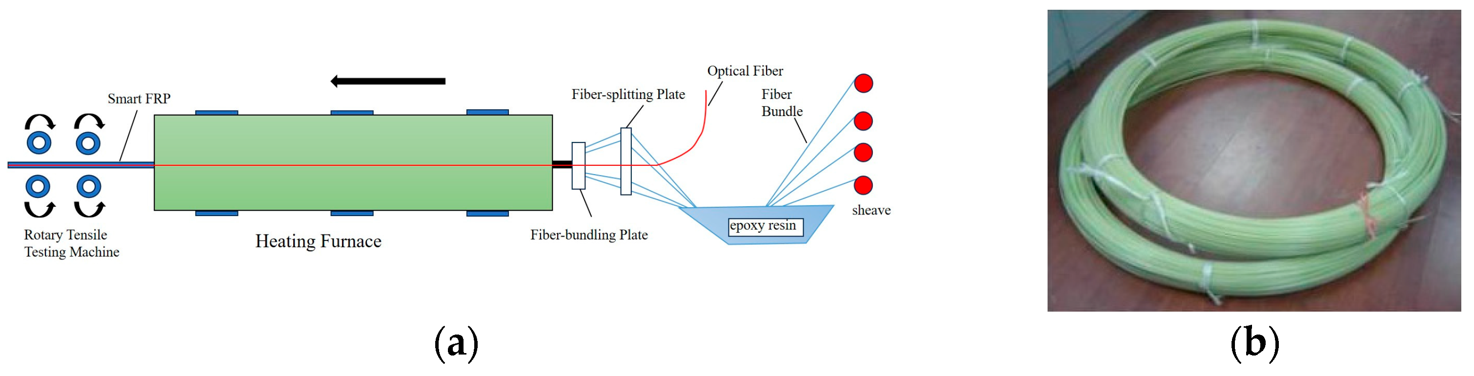
In this experiment, the glass fibers produced by Beijing Saint-Gobain Vetrotex Glass Fiber Co., Ltd. (Beijing, China) and the FBG sensor elements manufactured by Shenzhen Accelink Technologies Co., Ltd. (Shenzhen, China) were adopted as the materials. The embedded optical fiber smart rebars are prepared using a “high-temperature composite molding process”: during the processing of GFRP rebars, FBG sensing elements and glass fiber filaments are compounded with resin at high temperature and cured at high temperature to form an integrated structure. Since optical fibers are slender and their coating and protective layers are polymers, they have natural compatibility with GFRP materials and do not change the basic properties of GFRP. The epoxy resin matrix can isolate the impact of temperature fluctuations and humidity erosion on the optical fibers, and the GFRP material can improve the overall mechanical properties. Both lay a material foundation for the long-term stable operation of FBGs. The production process is shown in Figure 1a, and the appearance of the finished product is shown in Figure 1b.

2.2. Mechanical and Sensing Properties of Smart Rebars

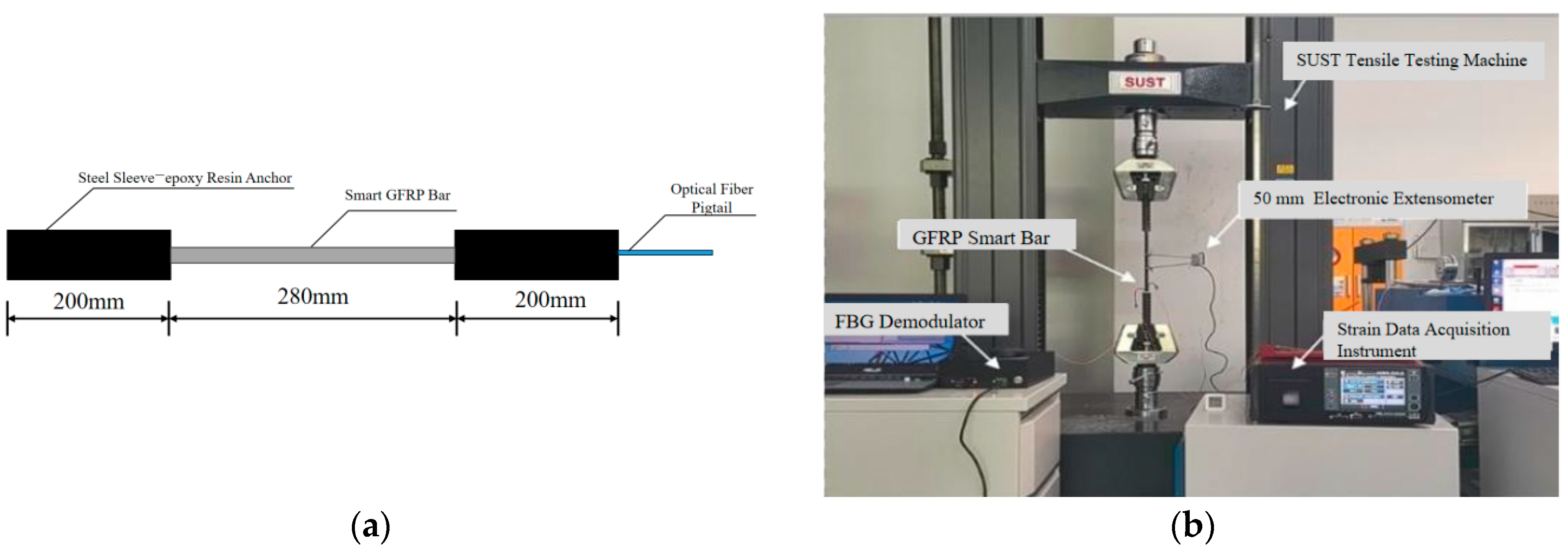
According to GB/T 30022-2013 “Glass Fiber Reinforced Polymer Bars” and GB/T 26743-2011 “Fiber Reinforced Polymer Bars for Structural Applications” issued by the Standardization Administration of the People’s Republic of China [21,22], the standard specimen length of the smart rebars is 680 mm with an anchorage length of 200 mm. The standard tensile specimen is illustrated in Figure 2a. Tensile tests on the smart rebars were conducted using epoxy iron sand anchorage, with the tensile rate controlled by a displacement of 2 mm/min. The mechanical property testing device is shown in Figure 2b.
The mechanical property test results are presented in Table 1. The standard value of the tensile strength of the smart rebars is ≥700 MPa; the elastic modulus is 47 GPa, and the ultimate elongation is 2.4%, which are higher than those of ordinary GFRP rebars (tensile strength: 500–650 MPa, elastic modulus: 40–45 GPa, ultimate elongation: 1.5–2.0% [23,24,25]). This performance advantage enables the smart rebars to better adapt to the coordinated deformation of metal roofs under wind loads, avoiding local damage caused by stiffness mismatch or insufficient ductility, and fully meeting the wind resistance reinforcement requirements of metal roofs.
In accordance with the national standard JG/T 422-2013 “Fiber Bragg Grating Strain Sensors for Civil Engineering” [26], fiber optic strain collection was carried out on the smart rebars. The strain sensing range is 0~10,000 με, the strain sensing sensitivity coefficient is 1.2 pm/με, the strain transfer efficiency is 88.33%, the linearity is 0.999, and the repeatability error is 0.05% (far lower than the specification requirement of ≤0.5%), indicating stable and reliable sensing performance. Compared with traditional external FBG sensors (strain transfer efficiency: 60–75% [27,28]), the smart rebars, through GFRP-integrated packaging, significantly improve the strain transfer efficiency, effectively isolate environmental interference, and ensure the accuracy of monitoring data.

2.3. Experimental Setup and Installation of Smart Rebars

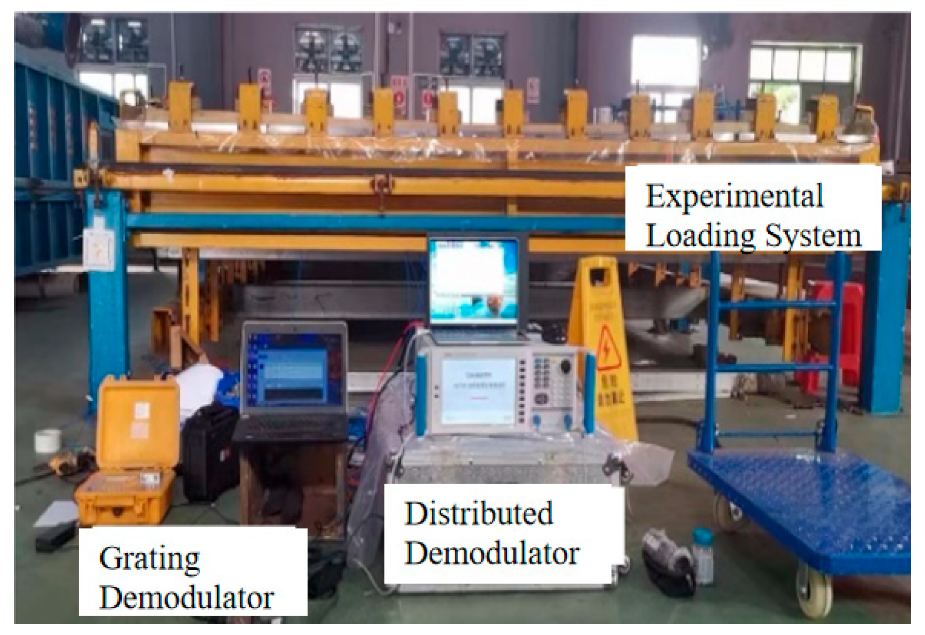
The main experimental setup is a metal-roof wind resistance testing machine, consisting of four parts: a test pressure box, a fan duct, a centrifugal fan, and control equipment. The plane size of the box was 3.86 × 7.70 m2, divided into three independent units along the height direction. The upper and lower boxes simulate the different wind conditions through independent air sources. The middle specimen frame was the roof installation area, with sealing strips set around to effectively seal the specimens and ensure wind load application efficiency. The experimental setup is shown in Figure 3.
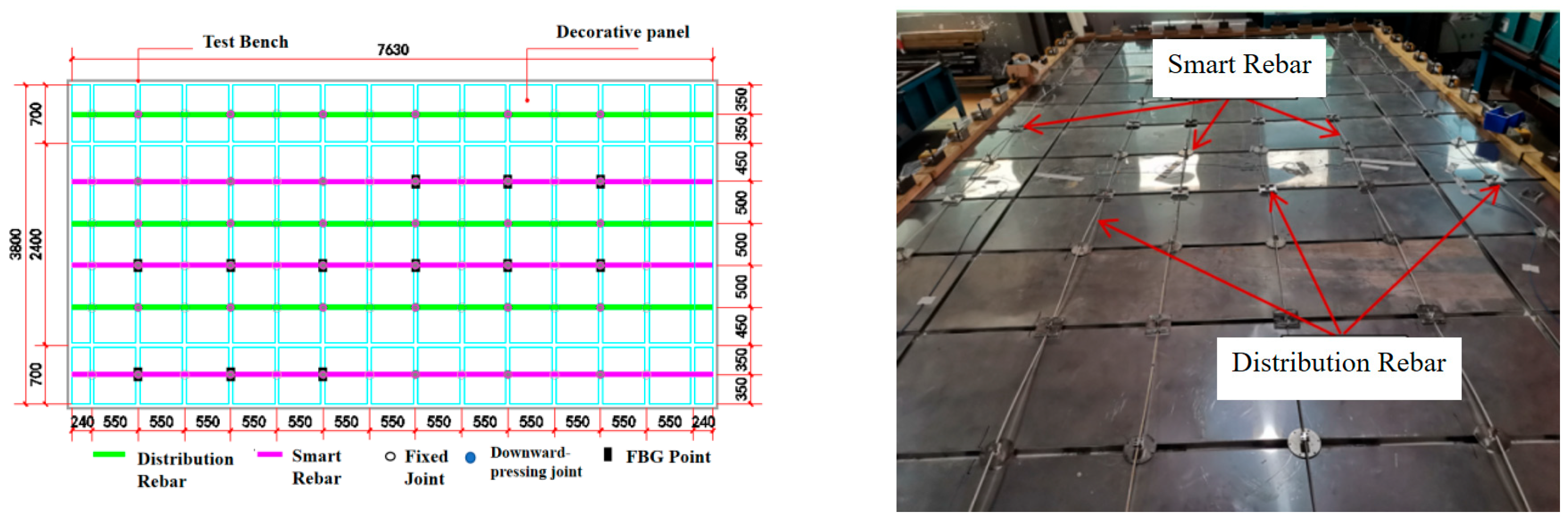
The research team fabricated a metal roof with dimensions of 3.76 m (width) × 7.5 m (length). Since the long side of the roof is the primary load-bearing direction, 6 GFRP sensing rebars were arranged along the length of the panel. Among these rebars, 3 are distributed optical fiber rebars, and the other 3 are FBG smart rebars (Smart Rebar #1 with 3 equidistantly spaced measuring points; Smart Rebar #2 with 6 equidistantly spaced measuring points; Smart Rebar #3 with 3 equidistantly spaced measuring points), which are arranged alternately at intervals. The 6 GFRP sensing rebars are symmetrically and uniformly placed on the decorative panels of the test specimen: 4 rebars are installed in the weakly constrained central area of the roof, with a spacing of 0.5 m between adjacent rebars; the 2 edge rebars are fixed at the midpoints of the decorative panels, 0.35 m away from the roof ends. The smart rebars are mechanically anchored via the fixed nodes of the roof panel [29]. The nodes adopt an integrated “bolt + buckle” design, eliminating the need for on-site welding and enabling single-person operation. Compared with the traditional scheme of “first reinforcing (bonding GFRP rebars) then monitoring (arranging sensors)”, this design significantly improves construction efficiency. After installation, pre-tensioning is applied to the smart rebars by pressing down the nodes. In this experiment, the pre-tension strain is controlled at approximately 500 με. The straightening of the smart rebars eliminates the inelastic deformation caused during installation, ensuring that they preferentially participate in load-bearing when the roof shows a tendency of wind uplift, thus enhancing the response sensitivity of the monitoring system. The FBG measuring points are designed to be located between the fixed nodes and the downward-pressing nodes to ensure that the rebars enter a pre-tensioned state after the nodes are pressed down. In this experiment, the measuring points are arranged at the downward-pressing nodes, with one point set every two decorative panels, so as to cover different positions of the entire roof decorative panel. The installation layout is shown in Figure 4.

3. Experimental Results and Analysis

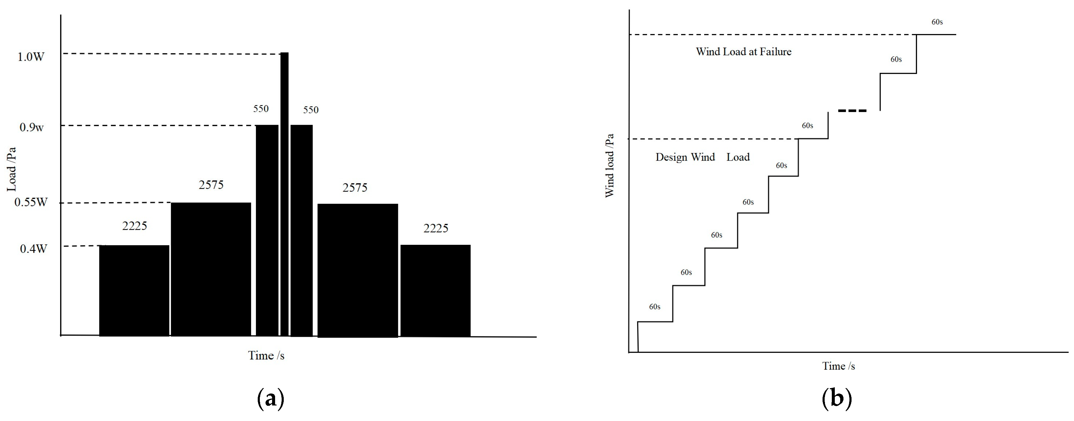
The test adopts the wind uplift resistance test method for metal roofs specified in Chapter A.6 of the Guangdong Provincial Standard DBJ/T 15-148-2018 “Technical Specification for Metal Roofs in Strong Wind-Prone Areas” [30]. The design wind pressure was W = 8.01 Kpa, and the test was conducted continuously through dynamic wind pressure detection and static wind pressure detection. The dynamic pressure-loading cycle includes ascent and descent phases: the pressure ascent time shall not exceed 2 s, the descent time shall not exceed 1 s, and a single fluctuation cycle shall not exceed 3 s. After the dynamic wind pressure detection, if the specimen does not fail, static wind pressure detection shall be carried out until it fails. Static wind pressure loading shall be carried out step by step, with each level maintained for 60 s until the specimen fails, as shown in Figure 5. Real-time data collection is performed during cyclic loading. The monitoring data collection during the test is mainly divided into three parts: (1) Initial strain measurement after installation; (2) real-time high-frequency collection of embedded FBG smart rebars and static scanning of distributed rebars during dynamic/static loading; (3) final data measurement after wind uplift failure.

3.1. Initial Strain Measurement

After all smart rebars were fixed, a full-roof initial evaluation scan was performed. Three consecutive measurements were completed, and after confirming no data differences, the third measurement data were taken as the initial value.

3.2. Dynamic Monitoring During Dynamic Loading Cycle Stage

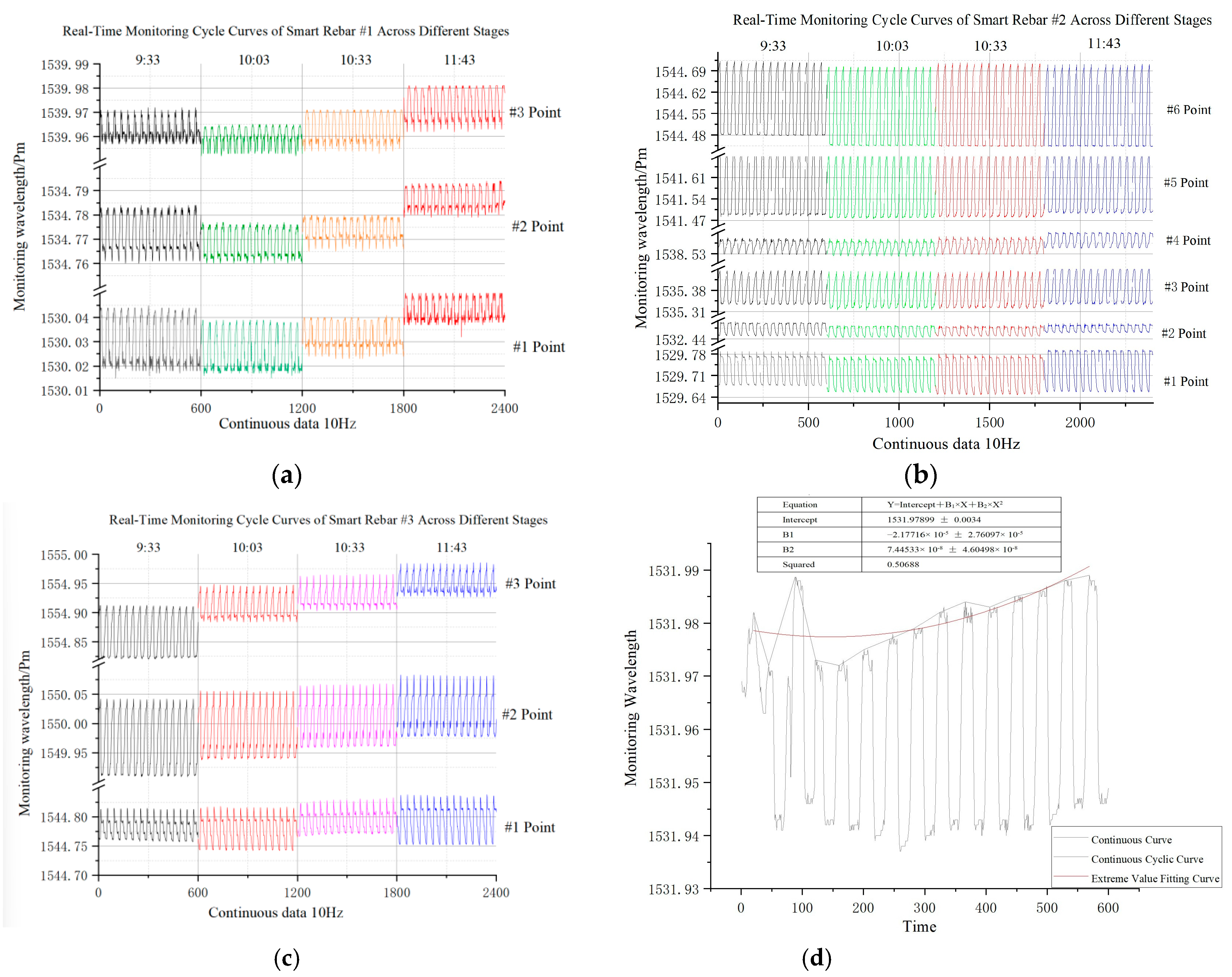
During the dynamic loading stage of the test, a 100 Hz FBG demodulator was used for continuous dynamic data collection of smart rebars, as shown in Figure 6. As can be seen, the sensing rebars monitor 14 dynamic loading cycles per minute, with an average duration of 4.28 s (During the conversion from wind suction to wind pressure, as well as at the wave crests and wave troughs of the loading cycle, the equipment exhibits a short period of flat delay, approximately 1.3 s), which is consistent with the preset loading scheme. Within similar cycle periods (1 min), the test data of the smart rebar grating points showed a good sinusoidal change, and the amplitude slightly changed in a short time, as shown in Figure 6a–c. This result indicates that the smart rebars and the metal roof form a good “rebar–panel” integrated force-bearing system through anchorage nodes, which can jointly resist wind loads and avoid local independent deformation of the roof. At the same time, the monitoring system can accurately capture the strain changes of each measuring point on the roof, indicating that encapsulating FBG sensors in GFRP results in stable sensing performance without interference. With the progress of the test, the strain vibration amplitude at each position in the smart rebars gradually increased, and the maximum peak value showed a gradual upward trend. Among the rebars, the change trends of Smart Rebars 1# and 3# installed on the side were more obvious (Figure 6d). The continuous arrangement of smart rebars will further improve the integrity of the roof panels, and the two form a complete, continuous force-bearing “rebar–plate” system. Under wind loads, they deform coordinately, and the smart rebars uniformly transfer the load in the local high-stress areas to the entire roof system, thereby optimizing the force transfer path. This redistribution prevents premature roof damage due to local stress exceeding allowable limits and verifies the feasibility of the proposed reinforcement scheme.

3.3. Dynamic Monitoring During Wind Uplift Failure Stage

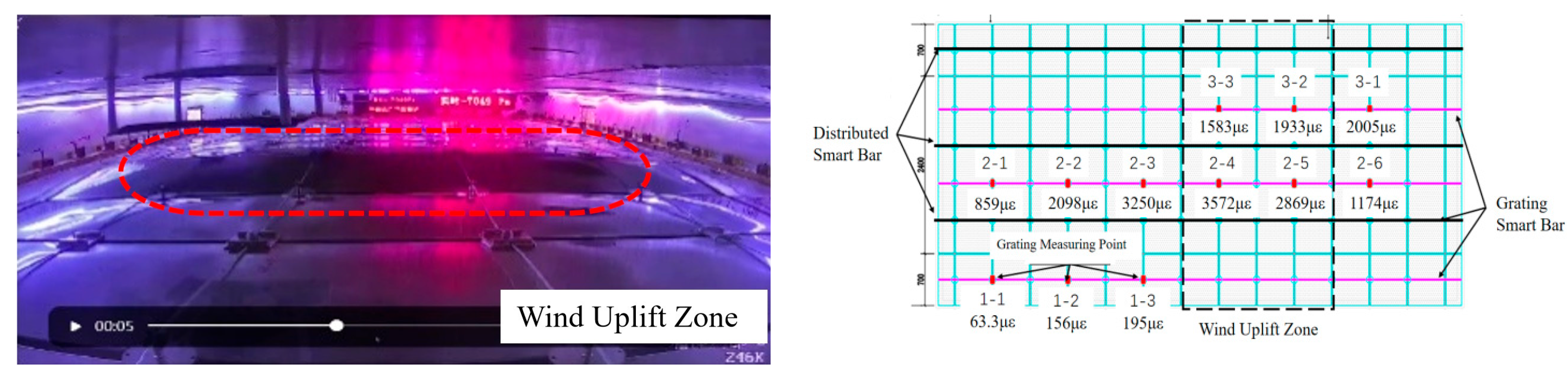
With the gradual increase in load, the curling of the roof panel and the clamp were damaged. The self-tapping screws of the decorative panels in rows 3 and 4 in the monitoring area loosened under wind pressure, the decorative panels showed a tendency to fly up, and the decorative panels in the nearby area exhibited obvious protruding deformation. The damaged area and details are shown in Figure 7.
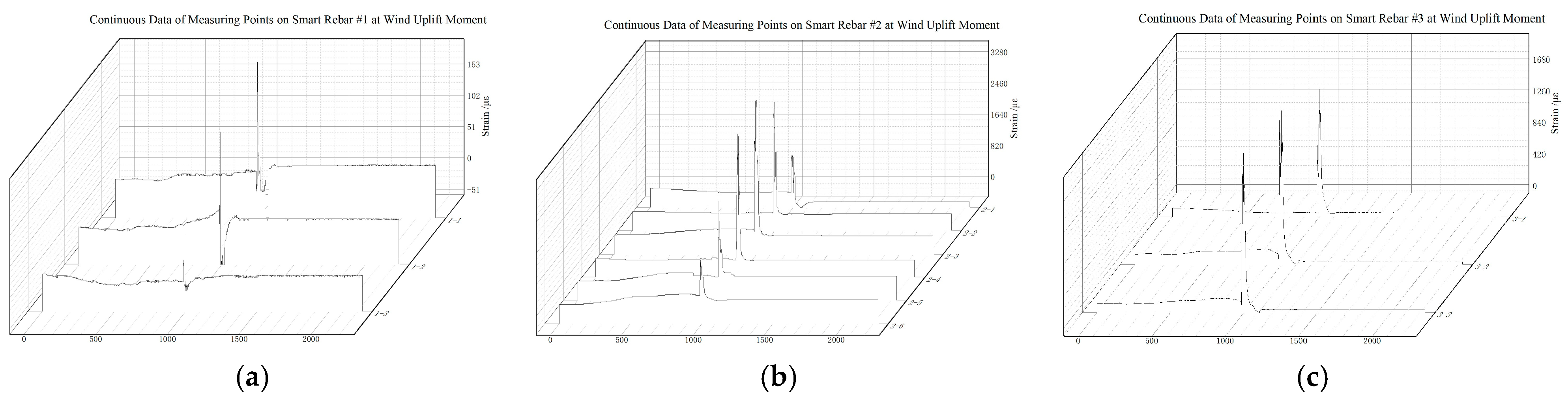
From the real-time data monitored by the smart rebars (Figure 8), it can be seen that: (1) When the decorative panel structure undergoes wind uplift failure, the FBG smart rebars can acutely capture the data change at the moment of wind uplift, and the detailed data are shown in Table 2. (2) During the test, the strain of the monitored FBG sensors showed an obvious sudden change of about 2000 με, and the sudden change value gradually decreased from the damaged area to the undamaged area (strain of measuring points in the damaged area > 2000 με, strain in the undamaged area < 500 με). The smart rebars connect discrete metal panels into a continuous load-bearing unit, optimizing the force transfer path of the roof. When wind load acts on the roof panels, part of the load is directly transmitted to the purlins through the panels, while the other part is transferred to the smart rebars via the connection nodes between the panels and the smart rebars. The smart rebars uniformly distribute the load in local high-stress areas to the entire roof system, achieving uniform force transfer of “local load → smart rebars → overall system”. This balances the stress distribution among all roof components and nodes, avoiding local failure caused by single-point overload and thereby slowing down the spread of overall roof failure. (3) At the moment of wind uplift failure, the smart rebars can effectively limit the splashing of decorative panels. After the wind stops, the measured strain value at each measuring point returns to a level similar to that before the wind began. This outcome indicates that the GFRP material can effectively protect the FBG sensors from failure due to cyclic loads, confirming the dual stability of the mechanical and sensing properties of the smart rebars under extreme working conditions.
By analyzing the data during the wind uplift failure stage and combining it with the deformation of the roof panel on-site, a quantitative index and graded-control system for FBG sensor monitoring were established: The Level 1 alarm value was 1800 με. At this time, attention should be paid to the alarm times and magnitude, and the monitoring of data change trends of this point and surrounding sensors should be strengthened. The Level 2 alarm value was 2400 με. The location of the alarm should be positioned, and data from surrounding sensors should be introduced for analysis. When continuous high-level early warning occurs, safety inspections of relevant measuring points should be carried out to check whether the sensors are invalid, and key observations should be conducted in strong wind weather. The Level 3 alarm value was 3000 με. The alarm location should be locked, and the inspection area should be expanded, focusing on checking the welding quality of the roof panel and the connection quality of anchor bolts, and timely reinforcement should be carried out for high-risk areas. This graded-control system realizes the closed-loop management from “data monitoring” to “risk response”, providing a scientific technical basis for the active wind resistance of metal roofs. In practical engineering, there are significant differences in the dimensions, materials, support forms, smart rebar layout density, load types, and service environments of metal roofs. For practical applications, alarm thresholds need to be calibrated and optimized through targeted tests or numerical simulations based on the specific structural parameters, operating conditions, and environmental conditions of the project to ensure the accuracy and reliability of monitoring and early warning.

3.4. Static Positioning Monitoring After Wind Uplift

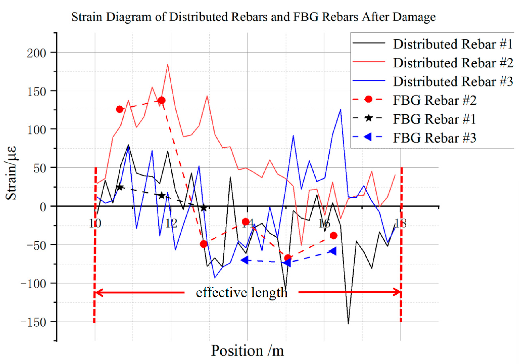
After the wind pressure of the loading system was completely stopped, static data collection was performed on the optical fiber smart rebars and FBG smart rebars, and the curves are shown in Figure 9. In combination with the layout of the smart rebars, the range of 10–18 m in the figure corresponds to the actual measurement area of the roof panel, and further analysis of the data is conducted in the following sections.
(1) The main damage area of the test decorative panel is the middle part of rows 3 and 4, which breaks away from the keel and is 1.34 m away from the edge of the test bench. Combined with the data of Smart Rebar 2#, the maximum tensile strain occurred in the range of 11~12 m (1~2 m from the edge), with a maximum tensile strain of 143 με. This strain distribution was completely consistent with the damage area, indicating that the smart rebars can not only play a constraint role at the moment of failure but also achieve accurate positioning of the damage area through static scanning, providing a clear basis for subsequent maintenance.
(2) For each measuring point of Smart Rebar 2# (6.25 m, 5.05 m, 3.95 m, 2.85 m, 1.75 m, and 0.65 m from the edge, respectively), the tensile stress at 0.65 m and 1.75 m was relatively large and located in the damage area. Among the measuring points, the tensile strain at 1.75 m was 137.5 με, which was consistent with the stress state at a similar position of Smart Rebar 3#. The distributed arrangement of the above smart rebars can realize the monitoring of the overall stress of the roof.
(3) Along the axial direction of the smart rebars, the lifted decorative panels exert pressure on adjacent areas, inducing bending in the smart rebars, with areas experiencing local bending showing local compression. This abnormal signal can be used as a “hidden damage early warning index”. In practical engineering, combined with the change in this signal, the loose connection between the roof and the keel can be identified in advance to avoid explicit damage.
It should be added that the smart rebars are fabricated by high-temperature compounding of FBGs, glass fiber filaments, and resin. The damage localization accuracy obtained in this experiment is based on the standard installation process, constant temperature, and short-term test conditions in the laboratory. When the smart rebars are subjected to long-term loads or harsh environments (such as high-temperature and high-humidity environments), the resin matrix and internal fibers are prone to damage, thereby affecting the monitoring accuracy and reinforcement effect of the smart rebars. The magnitude of this impact requires further research in subsequent work.

4. Conclusions

An intelligent monitoring method for metal roofs based on embedded optical fiber (grating) smart rebars was proposed in this work. The key link of this method is the development of smart rebars that meet the needs of practical engineering monitoring while taking into account reinforcement. These smart rebars integrate both sensing and load-bearing functions, combining structural health and safety monitoring with the reinforcement of metal roof panels to improve the overall wind resistance of the structure. Based on this, the following conclusions can be drawn:
  • The embedded FBG smart rebars possess stable and reliable high-frequency real-time monitoring capabilities. During wind load application, at the moment of wind uplift failure, and after failure, they can accurately capture the dynamic strain characteristics of the measured areas, effectively reflecting the stress state and damage distribution of the roof. This successfully addresses the issues of traditional external sensors being prone to damage and lacking data accuracy.
  • Through node anchorage, the smart rebars form a “rebar–panel” cooperative force-bearing system with the metal roof, improving the overall stiffness of the roof and suppressing wind-induced deformation. The smart rebars connect discrete metal panels into a continuous load-bearing integrated structure, uniformly transferring loads from local high-stress areas to the entire roof system and optimizing the roof’s force transfer path. This balances the stress distribution among all roof components and nodes, avoiding local failure caused by single-point overload. The experimental results show that the smart rebars effectively restrict the warping deformation of decorative panels and prevent secondary disasters induced by roof panel splashing.
  • Based on the experimentally measured strain data and the degree of roof damage, a graded-control index system is established, including a first-level alarm threshold of 1800 με, a second-level alarm threshold of 2400 με, and a third-level alarm threshold of 3000 με. Each level of alarm corresponds to specific disposal measures, enabling a closed-loop management system that links data monitoring to risk response.
  • Since no benchmark specimens without smart rebars were included in this experiment, the improvement in wind resistance performance and stiffness range of metal roofs composed of smart rebars cannot be quantified by direct experimental data. Consequently, the enhancement effect can be only inferred from the observed experimental phenomena and supported by relevant literature data. In addition, the experimental conclusions are drawn based on the laboratory standard process conducted under constant temperature and humidity conditions and are based on short-term tests. The influence of long-term loads and harsh environmental conditions on the accuracy and durability of smart rebars has not yet been explored. In the follow-up research, the influence of each factor on the monitoring accuracy and reinforcement effect of smart rebars can be quantified by changing test variables such as roof dimensions, smart rebar layout density, load types and temperature–humidity environments, so as to establish a parameter calibration method applicable to different engineering scenarios. Special tests on the stress behavior of smart rebars, roof panels and other related components can be carried out to deeply explore their mechanical mechanisms under wind uplift and improve the theoretical system of the “monitoring–reinforcement” cooperative effect of smart rebars. Furthermore, combined with practical engineering cases, the installation process and threshold calibration method of smart rebars can be optimized, the long-term service performance monitoring of smart rebars can be carried out, and finally, technical guidelines that can directly guide engineering practice can be formed.

Author Contributions

Investigation, Data curation, Formal analysis, L.Q.; Supervision, Writing—review and editing, Z.Z.; Data curation, Formal analysis, Writing—original draft, Writing—review and editing, J.X.; Methodology, Supervision, Writing—review and editing, R.L.; Conceptualization, Methodology, Supervision, Funding acquisition, Writing—review and editing, C.L. All authors have read and agreed to the published version of the manuscript.

Funding

This research was funded by General Program of Natural Science Foundation of Beijing [Grant No. 8242009]; Jiangsu Marine Structure Service Performance Improvement Engineering Research Center; Jiangsu University Key (Construction) Laboratory of Offshore Floating Wind Power Technology and Equipment; Doctoral Research Startup Fund of Nantong Institute of Technology [Grant No. 2025XKB08]; Research Project of Jiangsu Civil Engineering and Architecture Association [Project No. JSTJXH25112] and the University-Level Research Project of Nantong Institute of Technology [Project No. 2024XK (Z) 09].

Data Availability Statement

The original contributions presented in this study are included in the article. Further inquiries can be directed to the corresponding author.

Conflicts of Interest

Authors Lan Chunguang and Qian Linfeng were employed by the company Beijing Building Construction Research Institute Co., Ltd. The remaining authors declare that the research was conducted in the absence of any commercial or financial relationships that could be construed as a potential conflict of interest.

References

  1. Ma, Z.S.; Sui, S.R.; Liu, Z.X.; Ren, Q.; Zhao, C. Analysis of wind uplift resistance test of metal roofing system. Build. Technol. 2022, 53, 1025–1028. [Google Scholar]
  2. Baskaran, A.; Molleti, S. Impact of air intrusion on the wind uplift performance of fully bonded roofing assemblies. Constr. Build. Mater. 2009, 23, 889–901. [Google Scholar] [CrossRef][Green Version]
  3. Baskaran, B.A.; Ko, S.K.P.; Molleti, S. A novel approach to estimate the wind uplift resistance of roofing systems. Build. Environ. 2009, 44, 723–735. [Google Scholar] [CrossRef][Green Version]
  4. Baskaran, A.; Murty, B.; Wu, J. Calculating roof membrane deformation under simulated moderate wind uplift pressures. Eng. Struct. 2009, 31, 642–650. [Google Scholar] [CrossRef]
  5. Surry, D.; Sinno, R.R.; Nail, B.; Ho, T.C.; Farquhar, S.; Kopp, G.A. Structurally effective static wind loads for roof panels. J. Struct. Eng. 2007, 133, 871–885. [Google Scholar] [CrossRef]
  6. Sivapathasundaram, M.; Mahendran, M. Development of suitable test methods for the screw connections in cold-formed steel roof battens. J. Struct. Eng. 2016, 142, 04016025. [Google Scholar] [CrossRef]
  7. Luo, Y.F.; Xiao, B.B.; Liu, S. Bearing capacity analysis of common profiled steel sheet roofing and its connectors. Prog. Steel Build. Struct. 2006, 8, 1–4. [Google Scholar]
  8. Xu, C.L. Experimental study on wind-resistant bearing capacity of roof panels of an international airport terminal. Struct. Eng. 2011, 27, 107–113. [Google Scholar]
  9. Long, W.Z. Discussion on technologies for improving wind resistance of metal roofing (Part II)—Starting from three wind uplift incidents of metal roofing of Capital Airport Terminal T3. China Build. Waterproof. 2013, 1–5. [Google Scholar]
  10. Ying, X.J.; Zhong, J.H. Failure cause analysis and reinforcement of metal roofing of Qiongtai Normal University Gymnasium. China Build. Waterproof 2015, 319, 14–17. [Google Scholar]
  11. Shi, D.W. Structural design and analysis of metal roofing with improved wind uplift resistance performance. Eng. Constr. Des. 2021, 448, 1–4. [Google Scholar]
  12. Bao, Y.Q.; Chen, Z.C.; Wei, S.Y.; Xu, Y.; Tang, Z.; Li, H. The state of the art of data science and engineering in structural health monitoring. Engineering 2019, 5, 234–242. [Google Scholar] [CrossRef]
  13. Habel, W.; Kohlhoff, H.; Knapp, J. Monitoring system for long-term evaluation of prestressed railway bridges in the new Lehrter Bahnhof in Berlin. Proc. SPIE Int. Soc. Opt. Eng. 2003, 5057, 1–12. [Google Scholar]
  14. Ko, J.M.; Ni, Y.Q. Technology developments in structural health monitoring of long-scale bridges. Eng. Struct. 2005, 27, 1715–1725. [Google Scholar] [CrossRef]
  15. Udd, E. Overview of fiber optic sensors. In Fiber Optic Sensors; Yu, F.T.S., Ed.; Marcel Dekker: New York, NY, USA, 2002; pp. 1–39. [Google Scholar]
  16. Li, H.N.; Li, J.; Song, G.B. Research progress on civil engineering structural control using piezoelectric smart materials. J. Build. Struct. 2005, 26, 1–29. [Google Scholar]
  17. Li, H.N.; Gao, D.W.; Yi, T.H. Research status and progress of structural health monitoring systems for civil engineering. Adv. Mech. 2008, 38, 151–166. [Google Scholar]
  18. Ouyang, Y. Performance Study on Concrete Frame Structures Strengthened with Glass Fiber Reinforced Polymer (GFRP) Sheets. Master’s Thesis, Zhejiang University, Hangzhou, China, 2001. [Google Scholar]
  19. Xiao, J.Z.; Huang, Y.J. Seismic performance and damage assessment of recycled concrete columns confined with GFRP tubes. China Civ. Eng. J. 2012, 45, 112–119. [Google Scholar] [CrossRef]
  20. Ou, J.P.; Zhou, Z. Fiber Reinforced Polymer—Fiber Bragg Grating Composite Sensing Bar. China Patent 02132998.0, 24 March 2004. [Google Scholar]
  21. GB/T 30022-2013; Glass Fiber Reinforced Composite Rebars. China Standards Press: Beijing, China, 2013.
  22. GB/T 26743-2011; Fiber Reinforced Composite Rebars for Structural Use. China Standards Press: Beijing, China, 2011.
  23. Chen, J.; Huang, G.L.; Chen, Q. Experimental study on tensile mechanical properties of GFRP rebars. Build. Sci. 2012, 28, 4–8. [Google Scholar]
  24. Yao, R.S. Experimental Research and Analysis on Mechanical Properties of GFRP Rebars and Anti-Corrosion Steel Bars in Marine Concrete Members. Master’s Thesis, Guangxi University, Nanning, China, 2021. [Google Scholar]
  25. Zhou, J.K.; Du, Q.Q.; Chen, L.H.; Ma, X.H. Experimental study on size effect in tensile mechanical properties of GFRP rebar. J. Hohai Univ. (Nat. Sci.) 2008, 36, 242–247. [Google Scholar] [CrossRef]
  26. JG/T 422-2013; Fiber Bragg Grating Strain Sensors for Civil Engineering. China Architecture & Building Press: Beijing, China, 2013.
  27. Li, H.; Zhu, L.Q.; Dong, M.L.; Lou, X.P.; Guo, Y.K. Analysis on strain transfer of surface-bonding FBG on Al 7075-T6 alloy host. Optik 2016, 127, 1233–1236. [Google Scholar] [CrossRef]
  28. Zhou, Z.; Wang, Q.; Hao, X.; Ou, J.P. Strain transfer analysis of the FBG sensor considering the creep of the concrete host. Sens. Actuators A Phys. 2016, 248, 112–120. [Google Scholar]
  29. Qu, T.; Tan, J.; Shi, X.; Long, X.; Lin, S. A Reinforced Wind-Resistant Clip System for Metal Roof Panels. China Patent CN113187159B, 27 July 2021. [Google Scholar]
  30. DBJ/T 15-148-2018; Technical Specification for Metal Roofing in Areas Prone to Strong Winds. Department of Housing and Urban-Rural Development of Guangdong Province: Guangzhou, China, 2018.
Figure 1. Production process and finished product diagram of fiber Bragg grating smart rebars. (a) Production process of smart rebars. (b) Finished product of smart rebars.
Buildings 16 00949 g001
Figure 2. Tensile performance test of smart rebars. (a) Standard tensile specimen. (b) Mechanical-property testing device.
Buildings 16 00949 g002
Figure 3. Schematic diagram of the experimental loading device.
Buildings 16 00949 g003
Figure 4. Installation and layout diagram of smart rebars.
Buildings 16 00949 g004
Figure 5. Schematic diagram of wind pressure loading. (a) Dynamic wind pressure loading diagram; (b) Static wind pressure loading diagram.
Buildings 16 00949 g005
Figure 6. Dynamic monitoring during the dynamic loading cycle stage. (a) Dynamic cycle curve of Smart Rebar 1#. (b) Dynamic cycle curve of Smart Rebar 2#. (c) Dynamic cycle curve of Smart Rebar 3#. (d) Amplitude of smart rebars.
Buildings 16 00949 g006
Figure 7. Schematic diagram of the wind uplift damage area.
Buildings 16 00949 g007
Figure 8. Real-time monitoring data of fiber Bragg grating (FBG) smart rebars. (a) Failure stage curve of Smart Rebar 1#. (b) Failure stage curve of Smart Rebar 2#. (c) Failure stage curve of Smart Rebar 3#.
Buildings 16 00949 g008
Figure 9. Static scanning data diagram after wind cessation.
Buildings 16 00949 g009
Table 1. Properties of smart rebars.
Diameter/mmTensile Strength/MPaElastic Modulus/GPaElongation/%Sensitivity Coefficient pm/μεTransfer Efficiency/%
5.5750472.41.288.33
Table 2. Statistics of strain at each measuring point at the moment of wind uplift failure.
Smart Rebar No.Measuring Point No.Maximum Strain/μεStatus of Measuring Point Location
Smart Rebar 1#1-163.3No obvious damage
1-2156.7No obvious damage
1-3195No obvious damage
Smart Rebar 2#2-1859No obvious damage
2-22869Bulging
2-33572Bulging
2-43250Flying
2-52098Flying
2-61174Bulging
Smart Rebar 3#3-12005Flying
3-21933Bulging
3-31583Bulging
Disclaimer/Publisher’s Note: The statements, opinions and data contained in all publications are solely those of the individual author(s) and contributor(s) and not of MDPI and/or the editor(s). MDPI and/or the editor(s) disclaim responsibility for any injury to people or property resulting from any ideas, methods, instructions or products referred to in the content.