1. Introduction
Natural-draft cooling towers (NDCTs) are large-scale reinforced concrete structures that can be idealised as thin rotational shells with very high slenderness ratios. Owing to their geometry and structural form, their global behaviour is strongly governed by stability phenomena rather than by material strength. Analytical investigations and numerical studies on reference configurations and real towers have consistently shown that global shell buckling constitutes the governing structural mechanism under permanent and wind actions, often controlling the ultimate capacity well before conventional strength limits are reached [
1,
2,
3]. This behaviour has been confirmed not only by classical studies but also by more recent investigations on large cooling towers, which continue to identify stability-related phenomena as a critical aspect of their structural response [
4]. As a consequence, the structural safety of NDCTs has long been assessed primarily in terms of buckling resistance, making these structures particularly sensitive to geometric nonlinearities and small deviations from the ideal shell geometry.
Within this physical framework, linear eigenvalue buckling analysis has become the standard approach for assessing the stability of natural-draft cooling towers. The first eigenvalue of the linearized stability problem, commonly expressed through the critical load factor
λcr, represents the multiplier applied to a reference load combination (denoted here as
P0, i.e., the chosen baseline self-weight-wind load combination for the eigenvalue problem) that would theoretically trigger buckling of the geometrically perfect shell. Despite its inherent idealizations,
λcr has become a practical global stability indicator in both research and engineering practice, particularly for preliminary design and comparative assessments [
2,
3,
5]. Similar stability-based indicators are also employed in broader shell design frameworks and recommendations, reinforcing the role of eigenvalue buckling factors as global measures of structural safety [
6]. Sectorial design recommendations, most notably those issued by VGB PowerTech, have explicitly incorporated
λcr into design criteria by prescribing minimum admissible values for combined permanent and wind actions, thereby consolidating its role as a key stability indicator in practical cooling tower design [
7]. In this context, the critical load factor is commonly defined as
where
denotes the linear buckling load of the geometrically perfect shell and
represents the reference load combination.
Beyond its role as a practical stability indicator, several authors have emphasised that the critical load factor
λcr should not be interpreted as a pure measure of structural resistance. Instead,
λcr represents a global safety factor that implicitly combines the effects of load uncertainties, material behaviour, geometric imperfections and modelling assumptions. From this perspective, the traditional design requirement
λcr ≥ 5 for cooling towers can be understood as an empirical margin intended to cover multiple sources of uncertainty within a single parameter [
5,
8]. On this basis, subsequent studies have revisited the conservatism of this threshold and suggested that slightly lower values of
λcr, typically in the range of 4.5–4.7, may be sufficient for modern cooling tower designs when the contributing effects are explicitly identified and properly controlled [
9,
10]. This reinterpretation underscores the need for greater transparency in the factors embedded in
λcr, particularly when used for preliminary design decisions.
Following the conceptual framework proposed by Krätzig, Andres, and Eckstein [
9], the global buckling safety factor may be interpreted as the product of partial contributions associated with actions (
λ1), material behaviour (
λ2), brittle failure (
λ3), geometric imperfections (
λ4) and modelling aspects (
λ5), i.e.,
Within this framework, the present work focuses on the contributions associated with geometric imperfections and numerical modelling. Given the geometric complexity of cooling towers and the absence of closed-form solutions, numerical modelling has long been an essential tool for the evaluation of buckling resistance. Finite element analyses have shown that the predicted critical load factor depends not only on geometry and loading, but also on modelling options such as element formulation, mesh density, idealisation of the support conditions and load application strategies [
1,
2,
11]. Classical shell buckling theory already acknowledged that discretization-related effects may lead to a non-negligible dispersion of numerical results, particularly for imperfection-sensitive structures [
12]. Recent numerical investigations on large shell structures, including cooling towers, have further confirmed that buckling predictions may exhibit noticeable variability depending on modelling assumptions and discretization strategies [
13]. More recent contributions stress that reliable buckling predictions require transparent, theory-consistent numerical modelling, explicitly accounting for discretization and modelling assumptions rather than treating analyses as black boxes [
14].
Wind loading is widely recognised as the dominant destabilising action for natural-draft cooling towers, and its representation has been extensively investigated in recent years. Recent studies have refined circumferential and vertical wind pressure distributions using wind tunnel tests, full-scale measurements and advanced numerical analyses, contributing to more realistic design-oriented wind load models for large cooling towers [
15,
16,
17,
18,
19]. While these advances significantly improve the characterisation of wind actions, they primarily address aerodynamic loading itself and do not explicitly examine the influence of geometric imperfections or numerical discretization on buckling predictions. Accordingly, and in line with common engineering practice, the present study adopts simplified and well-established wind load models.
The pronounced sensitivity of thin shells to geometric imperfections is a fundamental characteristic of buckling-dominated structures. Early experimental and theoretical investigations demonstrated that small deviations from the ideal geometry may cause a significant reduction in the critical buckling load, which led to the development of imperfection sensitivity concepts and design-oriented reduction factors. The IASS recommendations provided a seminal framework to account for this effect in cylindrical and spherical shells by means of equivalent imperfection models and knock-down curves [
20]. To overcome the limitations of these classical approaches for reinforced concrete shells, Tomás and Tovar extended the imperfection sensitivity concept through nonlinear numerical analyses, proposing reduction curves applicable to a broader range of shell geometries, including those representative of natural-draft cooling towers [
21]. More recent studies have confirmed that imperfection sensitivity remains a critical issue for thin shell structures and depends on geometry, loading conditions and modelling assumptions [
22,
23].
The reviewed literature indicates that the structural safety of natural-draft cooling towers is predominantly governed by global shell buckling, for which the critical load factor λcr derived from linear eigenvalue analysis remains the standard indicator in both research and engineering practice. At the same time, λcr implicitly aggregates the effects of several sources of uncertainty, among which geometric imperfections and numerical modelling options play a decisive role. While substantial efforts have focused on refined wind modelling and advanced nonlinear analyses, the combined influence of geometric imperfections and discretization on the predicted critical buckling load has received comparatively limited systematic attention for real cooling tower configurations. This is particularly relevant in current practice, where minimum λcr values are prescribed without separating individual uncertainty sources. The present study addresses this gap by (i) calibrating an imperfection-related term from imperfection-sensitivity curves under combined self-weight and wind actions, and (ii) quantifying discretization-induced variability through a systematic mesh/element study, thereby enabling a more transparent predesign interpretation of λcr as a global stability margin.
2. Finite-Element Modelling and Validation
2.1. Reference Cooling Towers and Numerical Models
The numerical framework adopted in this study is validated against two benchmark natural-draft cooling towers that have been widely used in the literature for stability and buckling investigations. These benchmarks are selected to cover both idealised and realistic structural configurations and loading conditions, ensuring that the numerical models are capable of reproducing the fundamental buckling behaviour of reinforced concrete cooling towers before addressing the specific research questions of this work. In this section, they are denoted as Benchmark B1 (Chen [
24]) and Benchmark B2 (Mang et al. [
1]); the prefix B identifies benchmark configurations, while the index (1–2) distinguishes the two reference towers.
The first benchmark B1 corresponds to a theoretical hyperbolic cooling tower with constant shell thickness subjected to self-weight only, originally analysed by Chen [
24]. This configuration provides a controlled reference case, free from additional sources of complexity, and is particularly suitable for validating the finite element formulation and the prediction of global buckling modes under self-weight loading. The second benchmark B2 is a real reinforced concrete cooling tower with variable shell thickness subjected to combined self-weight and wind actions, reported by Mang et al. [
1]. This case represents a realistic structural configuration and allows validation of the numerical model under practical geometric and loading conditions.
The geometric definitions, thickness distributions and material properties of both benchmark towers are adopted directly from the original sources without modification. The cooling-tower shell is idealised as a surface of revolution with vertical coordinate z measured from the base; S denotes the total shell height, T the elevation of the throat (minimum radius) above the base, rs the base radius at z = 0, a the throat radius at z = T, rt the top radius at z = S, and t the shell thickness, constant or height-dependent t = t(z).
The key geometric parameters of the two benchmark towers are summarised as following: B1 is a theoretical hyperboloid shell of constant thickness
t = 0.19 m, with
rt = 27.4 m,
a = 25.1 m,
rs = 39.3 m,
T = 31.4 m, and
S = 76.8 m. B2 is a reinforced-concrete cooling tower of variable thickness, with
rt = 38.52 m,
a = 36.33 m,
rs = 59.68 m,
T = 30.5 m, and
S = 120 m; its thickness varies along height as reported in [
25] (approximately from
t = 0.203 m in the central region up to
t = 1.017 m near the top and
t = 0.762 m near the base).
As a consistency check, the present implementation reproduces the benchmark eigenvalue buckling factors and the associated global mode shapes reported in the reference studies within typical engineering tolerance.
2.2. Finite-Element Formulation, Support Idealisation and Load Implementation
The finite element models are constructed to reflect standard engineering practice and to remain fully consistent with the benchmark studies used for validation. All analyses were performed in the finite-element environment ANSYS (v17.0). Linear eigenvalue (bifurcation) buckling analyses were carried out to obtain the first critical load factor λcr associated with the fundamental global buckling mode. The tower midsurface was discretized with isoparametric shell elements covering coupled membrane-bending behaviour. To assess discretization effects, both triangular and quadrilateral meshes were considered, using first-order (3- and 4-node) and second-order (6- and 8-node, midside-node) shell interpolations.
Support conditions are defined to realistically represent the structural behaviour of natural-draft cooling towers while maintaining compatibility with the reference studies. In all cases, the shell is assumed to be clamped at the base, restraining both translational and rotational degrees of freedom, which reflects the stiff connection between the tower and its foundation commonly assumed in design-oriented buckling analyses.
Loading is introduced through permanent actions, represented by self-weight (G), and wind actions (W), applied in accordance with linear eigenvalue buckling analysis.
For reproducibility, the complete set of discretization options (elements, supports and wind-load discretization cases) is summarised in
Table 1.
Wind loading is modelled using simplified pressure distributions commonly adopted in engineering practice and in the benchmark studies, in order to preserve a controlled loading framework consistent with the objectives of the present work. Details of the adopted pressure-field definition and the corresponding wind-load discretization cases (including circumferential and vertical resolution levels), together with the associated source references, are provided in
Table 1.
2.3. Eigenvalue Buckling Analysis and Validation Scope
For each numerical model, linear eigenvalue buckling analysis is performed to determine the critical load factor λcr associated with the first buckling mode. This factor represents the multiplier applied to the reference load combination that would theoretically lead to loss of stability of the geometrically perfect shell. The corresponding buckling modes are global in nature and involve characteristic circumferential and meridional deformation patterns typical of thin-shell instability.
The validation strategy follows the two complementary benchmark cases adopted from the literature. In the case of the theoretical cooling tower B1, validation focuses on the ability of the numerical model to reproduce the expected global buckling modes and critical load factors under self-weight loading. In the case of the real cooling tower B2, validation is extended to combined self-weight and wind actions, allowing assessment of the numerical model under realistic geometric and loading conditions. To provide explicit quantitative evidence,
Table 2 reports the benchmark critical factors
and the corresponding values obtained in the present implementation
for both towers, together with the percent differences. In both cases, the agreement with the published results is assessed not only through qualitative consistency of the buckling modes, but also by verifying that the first eigenmode belongs to the same global mode family reported in the reference studies (characteristic global circumferential-meridional deformation pattern for the corresponding load case). It is also noted that the benchmark B2 dates back to 1983 and therefore reflects the computational capabilities and element technology available at that time; nevertheless, the agreement achieved remains within a compact range.
The numerical models and procedures described in this section establish a controlled validation framework against which the effects of geometric imperfections (
λ4) and discretization options (
λ5) can be systematically assessed. By relying on reference geometries, load models and analysis strategies already reported in the literature and detailed in the reference [
25], this framework isolates the influence of imperfections and discretization from other sources of variability. Accordingly, the present section does not aim to refine wind modelling or ultimate limit state checks, but to provide a consistent numerical baseline for the sensitivity analyses developed in the following sections.
For reproducibility, the solver settings and the adopted definition/extraction of
P0 and
λcr are reported in
Section 2.4 and
Table 1.
2.4. Reproducibility Details
To facilitate independent verification of the reported ranges and figures, the key modelling options varied in the discretization models and the adopted definition of the reported outputs are consolidated in this subsection and summarised in
Table 1.
The tower midsurface is discretized with isoparametric shell formulations capturing coupled membrane–bending behaviour. Four shell element formulations are considered in the discretization study, characterised by the number of nodes and interpolation order: 3- and 4-node (first-order) and 6- and 8-node (second-order, midside-node) shells, using both triangular and quadrilateral topologies. Consistently with the discretization sensitivity results, the 8-node quadrilateral midside-node formulation is adopted as the reference element type; in ANSYS this is implemented using SHELL93 element (8-node structural shell), which provides a robust baseline with reduced mesh-size sensitivity compared with lower-order alternatives.
Mesh density is parameterized by a characteristic in-plane element size h, explored through a prescribed sweep from 3.0 m to 4.0 m in increments of 0.2 m, while maintaining consistent refinement rules in regions of pronounced curvature and near the base restraint. Mesh convergence is assessed through the stabilisation of the fundamental eigenvalue, using the relative change in λcr between successive refinements, with a convergence criterion of
The base restraint is modelled as clamped, restraining both translations and rotations; for sensitivity purposes, alternative implementations of this restraint (e.g., continuous vs. discrete constraint application at the base ring) are included in the discretization models while preserving the same global fixed condition. Wind loading is implemented through a controlled set of load discretization levels that represent the same analytical pressure field with different resolution: continuous representation, discretization in height, discretization in the circumferential direction, and combined height–circumferential discretization.
Eigenvalue buckling is computed in ANSYS from the standard linear bifurcation formulation about the prebuckling stress state. Stress-stiffening is activated to ensure consistent formation of the geometric stiffness matrix, and the eigenproblem is solved using the subspace method, extracting a sufficient number of modes to identify the fundamental global buckling mode. The reported λcr corresponds to the smallest positive eigenvalue associated with this first global mode. The reference load vector P0 is defined as the assembled nodal equivalent of the adopted load pattern (self-weight and/or wind, depending on the case). Using a fixed definition of P0 across all variants ensures that λcr is consistently interpreted as the multiplier of the same reference load pattern, enabling direct comparison across meshes, element families, support implementations, and wind-load discretization levels. Although the analyses were carried out in ANSYS v17.0, the reported trends are primarily formulation-driven rather than solver-version-specific, and similar qualitative trends are expected in other FE packages when equivalent formulations and modelling settings are adopted.
All reproducibility items described above are compiled in
Table 1, and the key notation used throughout the manuscript is provided in
Appendix A (
Table A1).
3. Geometric Imperfections Sensitivity (λ4)
In this section, the imperfection-related factor
λ4 is evaluated on two real natural-draft cooling towers: Case I–N (Niederaussem [
9,
28]) and Case I–B (Belleville [
2]). The prefix I denotes towers used for the imperfection-sensitivity analyses, whereas the suffix identifies the corresponding plant (N = Niederaussem; B = Belleville).
3.1. Imperfection Sensitivity in Concrete Shell Structures
The sensitivity of concrete shell structures to geometric imperfections is a well-established characteristic of buckling-dominated behaviour. Small deviations from the ideal geometry may lead to significant reductions in the critical buckling load, particularly when elastic instability governs the structural response. This phenomenon has been extensively documented since the seminal studies collected by the IASS recommendations [
20], where the concept of imperfection sensitivity was formalised through the comparison between linear and nonlinear critical loads. For homogeneous elastic shells, the imperfection sensitivity is commonly quantified by the factor
ρhom, defined as the ratio between the nonlinear critical load (
) and the linear elastic buckling load (
),
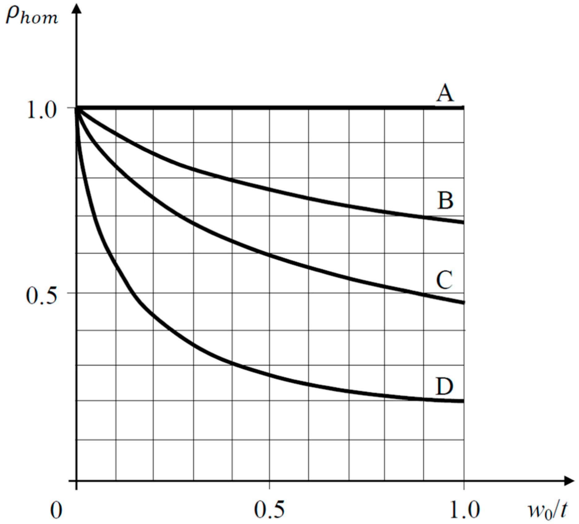
This coefficient provides a direct measure of the reduction in load-carrying capacity induced by geometric imperfections. The IASS graphical method [
20] establishes reference curves for different shell typologies, including annularly compressed cylinders of varying slenderness, axially compressed cylinders, and radially compressed spherical shells, allowing the estimation of
ρhom as a function of the normalised imperfection amplitude (
Figure 1).
In this framework,
w0 is a measure of the imperfection and
t is the thickness of the shell, and is classically decomposed into a calculated imperfection
ω′, typically associated with the maximum displacement obtained from a linear buckling mode, and an accidental construction imperfection
ω″, arising from erection tolerances. For shells built with rigid formwork and typical thicknesses between 0.05 and 0.07 m, practical values of
ω0 ≈
R/3500, where
R is the radius of curvature, are commonly reported in the literature [
10,
20].
3.2. Extended Imperfection Sensitivity Curves and Validation
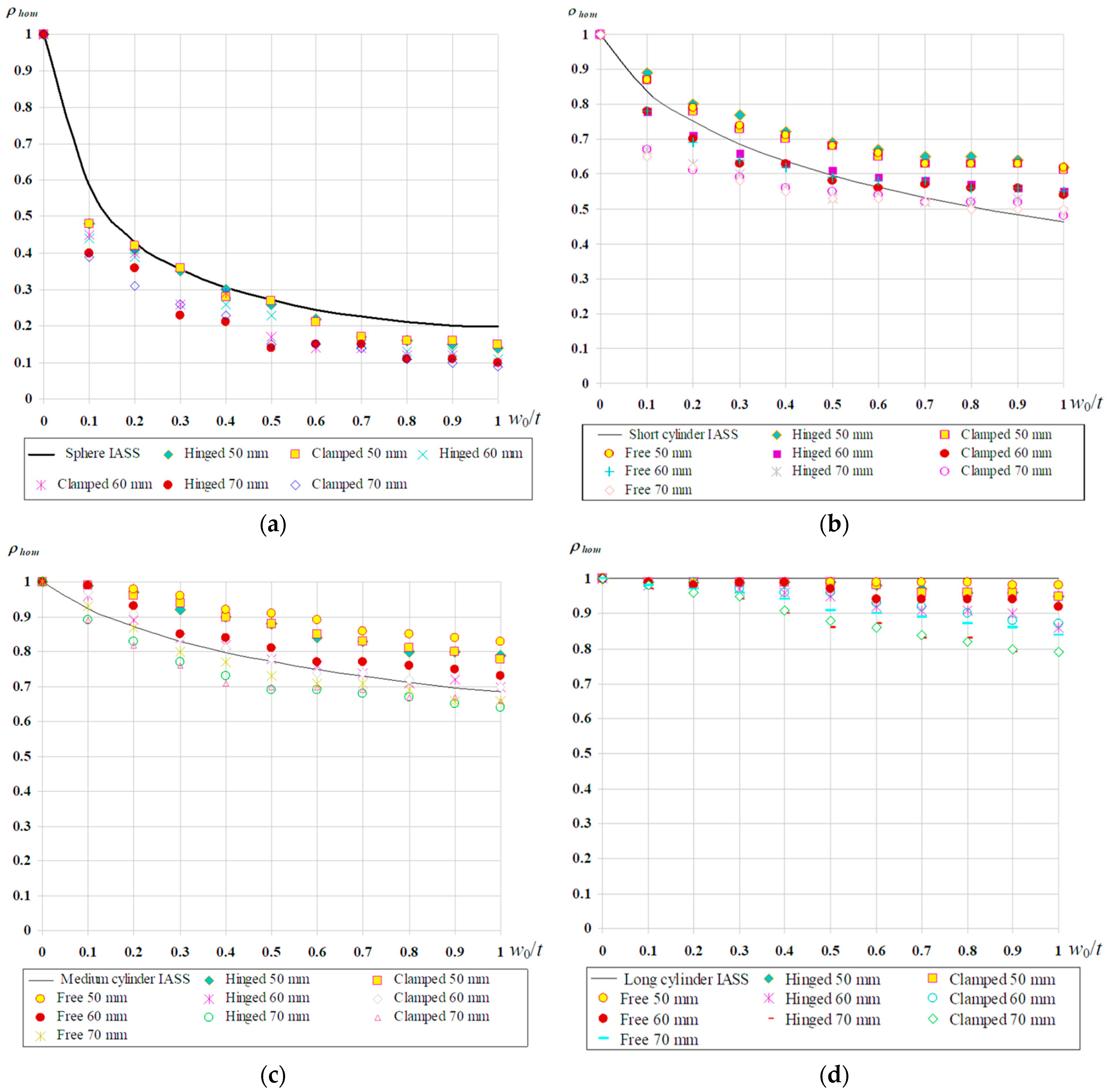
While the original IASS curves provide a valuable conceptual basis, their direct applicability to reinforced concrete shells with realistic support conditions and thickness variations is limited. To address this limitation, Tomás and Tovar [
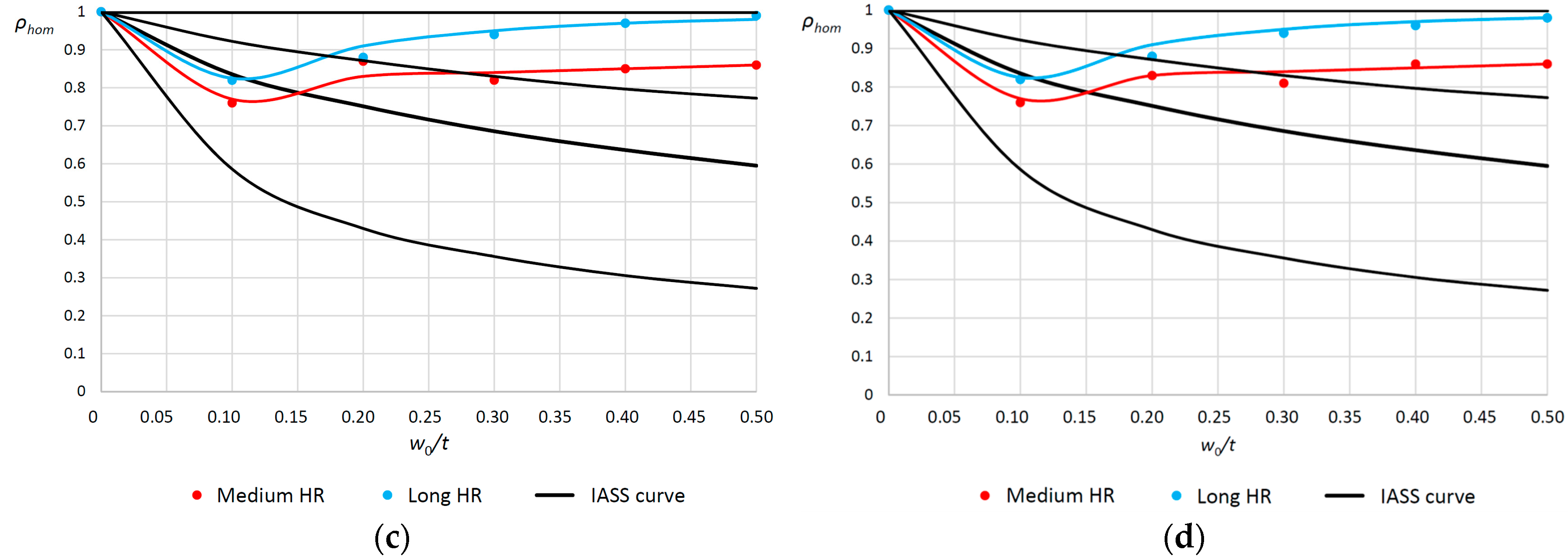
21] developed extended imperfection sensitivity curves through systematic nonlinear finite element analyses, covering a wider range of shell geometries, slenderness ratios and support conditions (
Figure 2).
These extended curves reproduce the classical IASS trends for long, medium and short cylindrical shells, while incorporating additional effects such as variable thickness, realistic support conditions and different shell typologies. The results confirm that imperfection sensitivity remains strongly dependent on shell slenderness and curvature but also highlight the influence of support conditions and load introduction on the resulting reduction factors.
3.3. Application to Natural-Draft Cooling Towers
The application of the imperfection sensitivity framework to natural-draft cooling towers requires additional considerations related to geometry, thickness and admissible imperfection amplitudes. Cooling towers are typically hyperboloids of revolution with large height-to-radius ratios, and their behaviour is more closely associated with the medium and long shell categories in classical buckling classifications. Following VGB-R610e [
7], the amplitude of the largest initial imperfection of the shell centre surface is restricted by construction tolerances. In particular, VGB-R610e limits the imperfection amplitude simultaneously by an absolute cap and by a thickness-related bound, which may be expressed in compact form as
Moreover, VGB-R610e additionally restricts the maximum angular change during erection to 1.5% (1.5 cm/m) in both meridional and circumferential directions, further supporting the interpretation of the above limits as practical execution tolerances. When thickness varies along the height, the VGB bound is applied locally using t = t(z), so that the admissible imperfection amplitude is governed by the local thickness profile. Consequently, the imperfection-sensitivity curves in the present study are expressed in normalised form (w0/t) and are considered up to w0/t = 0.5, consistently with the VGB thickness-related upper bound.
Two representative hyperboloid configurations are considered, corresponding to medium and long shells characterised by
H2/(
Rt) ≈ 1000 and
H2/(
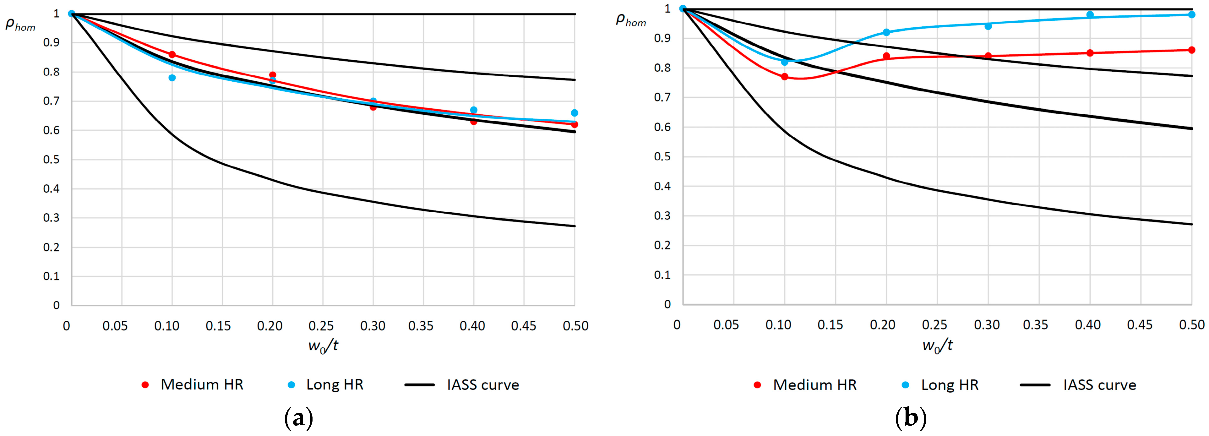
Rt) ≈ 10000, respectively, which are typical of real cooling towers. Imperfection sensitivity curves are generated for different load cases, including self-weight only (
G), wind only (
W), and combined self-weight and wind actions (
G +
Wmin,
G +
Wmax) (
Figure 3).
The resulting curves confirm that self-weight leads to a higher sensitivity to imperfections than wind loading, while combined load cases exhibit intermediate behaviour. This observation reflects the stabilising effect of circumferential stress redistribution induced by wind, compared to the predominantly compressive stress state generated by self-weight loading.
3.4. Calibration of the Imperfection Safety Factor λ4
For design-oriented applications, the imperfection sensitivity coefficient
ρhom is recast into a safety factor against buckling (
λ4) associated with geometric imperfections,
To account for the combined effect of self-weight and wind, a weighted formulation is adopted, in which the overall imperfection sensitivity coefficient is expressed as
with the weighting factor
α defined as
Equation (6) is intentionally formulated as a convex combination of the self-weight- and wind-related imperfection-sensitivity descriptors. The weighting factor α in Equation (7) is taken as a simple indicator for the relative influence of wind on the linear critical load, quantified through the reduction of when wind is added to self-weight. This choice is a heuristic, pragmatic predesign approximation that preserves the correct limiting behaviour (self-weight only, α → 0; wind-dominated response, α → 1) without introducing additional nonlinear calibration parameters. It should be noted that α is not intended to be a unique physical parameter; rather, it provides a simple weighting rule that may be refined in subsequent design stages if more detailed nonlinear evidence is available. Alternative weighting choices could be formulated based on more detailed nonlinear evidence, but this lies beyond the present linear screening scope. Within the present linear screening scope, however, the convex form of Equation (6) provides a transparent bounded estimate, between ρhom(G) and ρhom(W), while avoiding additional calibration parameters. Accordingly, Equations (6) and (7) provide a consistent and easily implementable rule to combine imperfection-sensitivity descriptors under mixed self-weight-wind loading within a linear predesign framework.
To provide a quantitative check of this predesign-oriented approximation, the mixed predictor in Equation (6) is assessed against the direct nonlinear combined-load results reported in
Table 3 for the representative medium hyperboloid under
G +
Wmin and
G +
Wmax, over the imperfection range
w0/
t = 0.1–0.5. Using Equation (7) to compute
α from the corresponding linear critical-load factors in
Table 3, the convex combination in Equation (6) reproduces
ρhom(
G +
W) with moderate deviations: for
G +
Wmin the mean (maximum) absolute relative error is approximately 5.6% (8.5%), while for
G +
Wmax it is approximately 2.2% (4.9%) over the considered imperfection range. Since Equation (6) is a convex combination, for any
α ∈ [0, 1] the combined descriptor is strictly bounded between
ρhom(
G) and
ρhom(
W). These results support the use of Equations (6) and (7) as a transparent heuristic approximation for predesign within the investigated domain, while direct nonlinear combined-load analyses remain the reference for project-specific verification.
From a mechanical standpoint, the reduction in imperfection sensitivity when wind is added can be interpreted as a consequence of membrane stress redistribution in the shell. Under self-weight-dominated conditions, the pre-buckling state is largely governed by meridional compressive membrane stresses, which promotes classical stability patterns that are strongly affected by geometric imperfections. Wind pressure modifies this stress field, locally inducing circumferential tension and redistributing meridional compression, thereby reducing the extent of uniformly compressed regions governing the critical mode and leading to a comparatively lower imperfection sensitivity under combined loading. It is noted, however, that this interpretation is established within the static wind-pressure representations adopted herein; more refined aerodynamic descriptions, dynamic wind excitation, or aeroelastic effects could alter the pre-buckling stress distribution and the associated imperfection sensitivity and should therefore be addressed at project-specific verification stages (see also
Section 5.1).
A representative numerical example for a medium hyperboloid of revolution subjected to self-weight and wind is reported in
Table 3, illustrating the influence of geometric imperfection amplitude on linear and nonlinear critical loads and on the resulting imperfection sensitivity coefficient.
For practical interpretation, the imperfection amplitude is reported in normalised form (
w0/
t) and the tabulated range is selected to cover the admissible construction-tolerance domain prescribed in VGB-R610e [
7], i.e.,
w0 ≤ min(0.5
t, 0.10 m). In particular, the upper bound
w0/
t = 0.5 corresponds to the thickness-related VGB limit and is consistent with the admissible imperfection range reiterated for NDCT shells in the buckling-safety discussion by Krätzig [
9]. Accordingly, the rows with
w0/
t = 0.5 in
Table 3 represent the practical upper-limit imperfection case within the codified tolerance domain.
Application of this approach to two representative nuclear cooling towers (Case I-N and Case I-B), whose geometries and loading conditions are well documented in the literature [
2,
9,
23,
28], results in values of
ρhom in the narrow range 0.707–0.727, corresponding to imperfection safety factor
λ4 between 1.38 and 1.41. These results are consistent across different geometries and loading scenarios, indicating a robust and transferable imperfection sensitivity range for practical cooling tower configurations.
3.5. Calibration of λ4 for NDCT Under Combined G + W
Although the theoretical values of imperfection sensitivity span a wide interval, with ρhom ranging approximately between 0.62 and 0.86 depending on load case and imperfection amplitude, the application to realistic cooling tower geometries subjected to combined self-weight and wind actions leads to a significantly narrower and more stable range.
Based on the results obtained in this study, a conservative and practically meaningful interval for the imperfection safety factor in natural-draft cooling towers may be defined as
This range reflects the dominant influence of self-weight loading, the moderating effect of wind actions, and the realistic values imposed on geometric imperfections by construction practice. In particular, these practical bounds are consistent with the construction-tolerance limits for cooling-tower shells codified in VGB-R610e [
7]. They provide a rational basis for incorporating geometric imperfections into a global predesign safety framework without resorting to excessively conservative assumptions.
It should be noted that the present calibration of λ4 is based on systematically verified nonlinear finite-element analyses and consistency with published numerical benchmarks. Direct experimental validation of global imperfection-sensitivity curves for full-scale reinforced-concrete natural-draft cooling towers is generally limited due to the scale and practical constraints associated with controlled instability testing. Consequently, λ4 should be interpreted as a design-calibrated, model-based imperfection factor within the framework of validated numerical shell modelling, rather than as a universal material or structural constant. Experimental evidence (e.g., reduced-scale tests or measured as-built imperfections combined with numerical back-analysis) could refine the quantitative bounds for specific tower typologies and construction quality levels, while the predesign-oriented decomposition framework adopted herein would remain unchanged.
The two real towers used as reference cases (Niederaussem and Belleville) were selected as well-documented full-scale NDCTs representative of conventional reinforced-concrete hyperboloidal shells and are used here as anchoring configurations for the calibration and interpretation of λ4. The proposed λ4 bounds should therefore be transferred only within the analysed geometric domain and modelling scope, whereas tower typologies departing from this family (e.g., markedly different thickness distributions, novel structural concepts, or ultra-slender shells beyond the typical NDCT slenderness range) would require project-specific numerical evidence and recalibration.
The proposed
λ4 range is intended to be applicable within the geometric domain covered by the analysed NDCT configurations, which corresponds to slender reinforced-concrete shells with
H2/(
Rt) of the order of 10
3–10
4, i.e., representative values around 1000–10,000 typically adopted for natural-draft cooling towers. Accordingly, extrapolation to shells with substantially lower slenderness ratios, different thickness distributions, or imperfection patterns outside the considered amplitude domain is not recommended without recalibration [
9].
The present framework focuses on geometric nonlinearity while assuming linear-elastic material behaviour for reinforced concrete. It is acknowledged that RC shells subjected to combined self-weight and wind actions may experience cracking and stiffness degradation, particularly in tension-dominated regions, which can influence both the pre-buckling stress distribution and the post-buckling response (e.g., Mang et al. [
1]). Moreover, in RC shells the reduction in load-carrying capacity due to geometric imperfections may interact with cracking-induced stiffness changes, so that geometric and material nonlinearities are not fully independent (Tomás & Tovar [
21]). In the context of the present study,
λ4 is formulated as a predesign-oriented imperfection factor calibrated on a linear-elastic baseline; inclusion of material nonlinearity would be expected to refine the quantitative bounds of the imperfection sensitivity curves, but not to modify the conceptual separation between geometric imperfection effects and other partial contributions adopted herein. For ultimate verification, materially nonlinear analyses remain necessary at the project-specific design stage.
4. Discretization Contribution and Numerical Modelling Uncertainty (λ5)
In this section, the discretization-related factor
λ5 is evaluated on two towers: Case D–B (Belleville [
2]) and Case D–T (theoretical tower [
5]). The prefix D denotes cases used for discretization and numerical-modelling uncertainty analyses, while the suffix identifies the tower/configuration (B = Belleville; T = theoretical tower).
4.1. Discretization in Buckling Analyses of Shells
In numerical buckling analyses of thin shell structures, discretization constitutes an inherent source of uncertainty that may significantly affect the predicted critical load factors. Unlike material properties or external actions, discretization is not a physical parameter but a modelling choice, and its influence becomes particularly relevant in stability-dominated problems where eigenvalues and mode shapes are highly sensitive to numerical approximations.
For natural-draft cooling towers, the combination of large dimensions, pronounced curvature variations and thin shell thicknesses leads to demanding requirements on the spatial discretization of the numerical model. Insufficient mesh refinement may result in artificial stiffening or spurious numerical modes, whereas excessive refinement leads to prohibitive computational costs without necessarily improving the reliability of the predicted buckling load. Consequently, a systematic assessment of discretization effects is required to identify acceptable modelling options and to quantify the associated numerical uncertainty.
4.2. Discretization Strategy and Mesh Configurations
The discretization strategy adopted in this study is based on structured meshes defined in the meridional and circumferential directions. Six different mesh sizes are considered, obtained by progressively refining the number of divisions along both directions while preserving the overall mesh topology and element type. This approach isolates the effect of mesh density from other modelling aspects and ensures consistency across the parametric analyses. The selected meshes span from relatively coarse discretisation suitable for preliminary assessment to highly refined meshes approaching mesh-consistent eigenvalue predictions.
The combination of the six mesh sizes with the four wind load cases defined previously leads to a total of 24 discretization-load configurations for each cooling tower. These cases are combined with the modelling options considered in the discretization study, namely: (i) element type (four shell discretisations corresponding to triangular/quadrilateral and first-/second-order interpolations, i.e., 3- and 4-node versus 6- and 8-node formulations); (ii) mesh density (six characteristic element sizes); (iii) wind-load discretization (four wind modelling cases, as defined above); and (iv) support idealisation (four alternative support models at the base). These variants preserve the same global rigid-base (clamped) idealisation adopted throughout the study and differ only in the numerical enforcement of the restraint at the base ring (continuous versus discrete constraint enforcement). Overall, this results in 4 × 6 × 4 × 4 = 384 eigenvalue FE models analysed per tower.
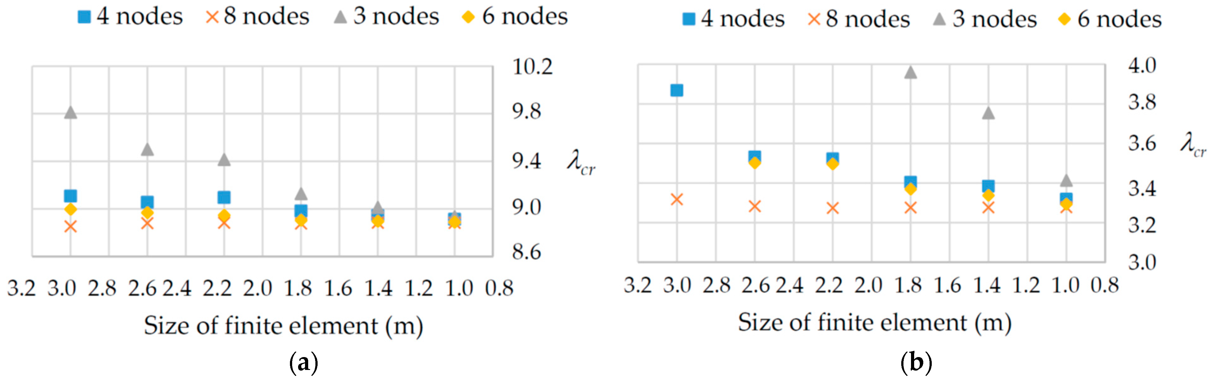
Figure 4 illustrates a representative subset of these models by varying shell element formulation and characteristic element size, while keeping the wind-pressure discretization (combined heightwise and meridional) and support conditions (continuous rigid supports) fixed.
The full dataset was post-processed by applying the mesh-consistency criterion defined in
Section 4.3 to identify engineering-acceptable discretisations. The resulting admissible bounds
λcr,max and
λcr,min, together with the discretization factor
λ5, are reported in
Table 4 (see also
Section 4.4).
Table 4 also reports, for each shell element formulation, the maximum relative variation in
λcr upon mesh refinement from 3 m to 1 m.
4.3. Evaluation of Discretisation Sensitivity on λcr
As shown in
Figure 4, discretisation effects lead to a non-negligible spread of
λcr values, even when the same loading scheme and support conditions are considered. While the qualitative ranking of element formulations is consistent in both towers,
Figure 4 also shows that the magnitude of discretisation-induced variability differs between Case D-B and Case D-T, confirming that discretisation effects are geometry- and configuration-dependent.
Within the rigid-base (clamped) class considered here, the different support implementations mainly affect the numerical enforcement of the base restraint and may shift the absolute level of
λcr, but they are not observed to govern the discretization-induced scatter that motivates
λ5. This is consistent with prior NDCT buckling studies indicating a limited influence of base flexibility on buckling loads for the investigated configurations (e.g., Mang et al. [
1]), while boundary conditions and sub-structure effects may become relevant in refined assessments (e.g., Krätzig [
9]).
In the discretization study, engineering-acceptable FE models are operationally defined as those that (i) provide mesh-consistent predictions of the first eigenvalue buckling factor
λcr and (ii) do not exhibit erratic outlier behaviour under systematic refinement within the considered element family. In practice, admissibility is enforced through the mesh-consistency requirement that the relative change in
λcr between two consecutive mesh refinements remains below 2%. This tolerance is adopted as an engineering-level mesh-consistency requirement for a global scalar response (the first buckling eigenvalue), consistent with assessing discretization adequacy through eigenvalue stabilisation under systematic mesh refinement (e.g., Chen [
24], among others). Only results satisfying this criterion are retained to limit the discretization-related scatter and to define the discretization partial factor
λ5; non-mesh-consistent cases and erratic outliers (notably for coarse first-order triangular discretizations) are discarded. Accordingly, only the screened admissible subset is used to calibrate
λ5, whereas all remaining cases are omitted from the calibration set. It is noted that adopting slightly stricter or looser tolerances (e.g., 1% or 3%) would mainly affect the size of the admissible subset, whereas the resulting practical bounds of
λ5 are not expected to change materially within the modelling assumptions considered.
The magnitude of this discretization-induced variability is quantified in
Table 4, which reports the maximum relative variation in
λcr obtained when refining the mesh from 3 m to 1 m for different finite element types, for both towers. The results indicate that discretization alone may lead to variations exceeding 15% in the predicted critical load factor, depending on the element formulation and tower geometry. In practical terms, this screening prevents non-mesh-consistent discretisation from unduly influencing the calibrated
λ5 range and ensures that the discretisation contribution is bounded under mesh-consistent conditions.
Figure 4 summarises a representative subset of the discretization models (fixed wind-pressure discretisation and rigid supports), highlighting the influence of element type and characteristic element size on
λcr; the corresponding definition of
λ5 is provided in
Section 4.4.
The larger dispersion observed for Case D-T compared to Case D-B is mainly attributed to the numerical sensitivity of the buckling eigenvalue problem to spatial discretisation. In Case D-T, a stronger dependence of λcr on mesh density and element interpolation is observed; therefore, coarse discretisations and lower-order formulations may not capture the instability field with sufficient fidelity, leading to increased variability of λcr. In contrast, a more stable λcr response is obtained for Case D-B under the same modelling assumptions, which results in a narrower dispersion band.
4.4. Definition of the Discretisation Factor λ5
Based on the dispersion levels observed in the discretization study, a discretisation-related modelling uncertainty factor
λ5 is defined to account for numerical modelling uncertainty within a predesign safety framework as
where
λcr,max and
λcr,min represent admissible upper and lower limits of the critical load factor associated with discretisation options within the set of engineering-acceptable models. It should be emphasised that
λ5 is an epistemic modelling uncertainty factor that accounts for discretization- and idealisation-related variability of
λcr; it is not a physical resistance factor and does not represent material strength, stiffness degradation, or other intrinsic structural capacity.
In this context,
Table 4 provides both element-wise sensitivity indicators and the admissible bounds
λcr,max and
λcr,min used to compute
λ5, ensuring direct traceability of the discretization calibration. Values associated with non-admissible coarse-mesh outliers are not considered in the calibration of
λ5 in accordance with the mesh-consistency criterion. For clarity, the mesh-consistency criterion refers to the < 2% stabilisation requirement for
λcr between consecutive mesh refinements defined in
Section 4.3, which is used to screen non-convergent cases and exclude coarse-mesh outliers from the calibration set. Accordingly,
λ5 is framework-dependent and should not be interpreted as a universal discretization factor. This highlights the importance of explicitly accounting for discretization effects, particularly in predesign stages where simplified numerical models are often employed.
4.5. Implications for Predesign and Modelling Practice
The results of the discretization study confirm that numerical modelling options can introduce variability in λcr comparable in magnitude to other sources of uncertainty. While refined meshes can reduce this variability, they do not eliminate it entirely, and their use may be impractical in early design stages or extensive parametric studies.
By introducing λ5 as an explicit discretization-related modelling uncertainty factor, the proposed framework provides a transparent and rational means of accounting for numerical modelling uncertainty without requiring excessively conservative assumptions. This contribution is particularly relevant for preliminary design assessment, where λcr is used as a global stability indicator and the numerical idealisation must remain both robust and computationally efficient.
The applicability domain of the present
λ5 calibration is bounded by the analysed configurations, since discretization sensitivity is influenced by tower geometry, thickness distribution, loading configuration, and modelling assumptions. Accordingly, the applicability domain of the present
λ5 calibration is bounded by the analysed configurations and, in particular, by the benchmark towers defined in
Section 2.1 and their characteristic height/radius/thickness proportions. It is recalled that NDCT shells are extremely slender (e.g., values such as
h/
t ≈ 840 have been reported for full-scale towers [
9]), so mesh sensitivity is inherently geometry-dependent. In line with prior observations that reliable generalisation requires the essential geometric descriptors to be specified, extrapolation of
λ5 beyond the present parameter bounds is discouraged. The range obtained from the two benchmarks is intended to be representative for preliminary assessment under similar conditions; however, for towers with substantially different geometries, support flexibility, or stiffening layouts, recalibration is recommended by applying the same mesh-consistency screening described in
Section 4.3. It is reiterated that true foundation flexibility and soil-structure interaction fall outside the present scope and require project-specific modelling (cf. [
9]).
Within this context,
λ5 complements the safety contributions associated with actions, material behaviour, brittle failure, and geometric imperfections previously discussed. Taken together, these contributions form a consistent basis for defining a global predesign safety factor for buckling, which is addressed in
Section 5.
5. Discussion: Global Predesign Safety Factor for Buckling (λcr)
5.1. Interpretation of λcr as a Global Predesign Indicator
As outlined in the Introduction, the linear critical load factor λcr from eigenvalue analysis is widely used as a screening metric for preliminary stability assessment of natural-draft cooling towers, particularly for rapid comparison of alternative geometries and configurations.
However, as shown by the results of this study,
λcr implicitly aggregates the influence of several distinct sources of uncertainty related to actions, material behaviour, brittle failure, geometric imperfections and numerical modelling. When these contributions are not explicitly identified, the interpretation of
λcr as a safety margin may become ambiguous, especially when simplified numerical models are employed. The present work provides a structured interpretation of
λcr as a global predesign safety indicator, whose meaning can be clarified by separating its underlying contributions. The applicability domain of the proposed partial-factor ranges is therefore stated explicitly in
Section 3.5 and
Section 4.5, and extrapolation beyond the analysed geometric bounds is discouraged.
Within this framework, λcr is not intended to replace final design safety checks or nonlinear verification procedures. Instead, it serves as a compact and transparent measure of global stability, suitable for predimensioning, parametric studies, and comparative assessment of different modelling assumptions, while remaining fully compatible with established design methodologies. The present decomposition of λcr into multiplicative contributions is an interpretative predesign construct applied to a global eigenvalue indicator, not a formal limit-state design format. In particular, λ1–λ2 are introduced only to align the predesign interpretation with familiar Eurocode partial-factor concepts for actions and reinforced concrete, whereas λ4–λ5 are model-based contributions derived from eigenvalue sensitivity and discretization studies within the adopted numerical framework and should not be read as normative partial factors.
Scope and limitations. The proposed interpretation of
λcr and its decomposition into partial contributions is intended as a predesign screening framework for rapid comparison and preliminary stability appraisal of NDCT geometries based on linear eigenvalue analysis. It is not a substitute for final verification. The proposed ranges are therefore applicable only within the modelling scope adopted herein, namely: (i) linear-elastic shell behaviour and eigenvalue buckling as a global stability indicator (with cracking and materially nonlinear RC response to be addressed at later design stages; see also the discussion in
Section 3.5 regarding potential implications for imperfection sensitivity and
λ4); (ii) rigid-base support idealisation (foundation flexibility and soil-structure interaction not considered), and (iii) simplified wind-pressure representations and limited wind-load discretisations (recognising that wind-field uncertainty, aerodynamic effects and site-specific wind characterisation may govern refined design). When any of these aspects is expected to be dominant, the present ranges should be regarded only as indicative and complemented by project-specific nonlinear analyses and code-compliant checks.
5.2. Partial Safety Contributions
Following the conceptual decomposition originally proposed in the literature on shell buckling safety, the global predesign safety factor is expressed as the product of five partial contributions accounting for the main sources of uncertainty affecting
λcr. These include the contribution associated with actions (
λ1), material-related uncertainty (
λ2), brittle failure (
λ3), sensitivity to geometric imperfections (
λ4) and numerical modelling uncertainty related to discretization (
λ5) [
5,
9].
The values and ranges adopted for λ1 and λ2 are consistent with current design practice and normative prescriptions, and therefore do not represent a departure from established safety concepts. The contribution λ3 reflects the brittle failure of the concrete, a characteristic that has long been recognised in the literature and that justifies the use of additional safety margins in this type of instability-dominated structures.
The selected values for
λ1–
λ3 are thus not introduced as novel proposals, but as a predesign-level alignment with established NDCT practice:
λ1 and
λ2 follow standard code-based partial-factor concepts, while
λ3 reflects the additional margin traditionally associated with brittle instability of reinforced-concrete shells. In this sense, the resulting order of four global range in
Section 5.3 should be interpreted as a screening-level synthesis consistent with long-standing buckling-safety concepts reported in the cooling-tower literature (e.g., [
9]), rather than as a universal acceptance threshold.
The imperfection-related contribution
λ4, derived from the imperfection sensitivity analyses presented in
Section 3, falls within a relatively narrow range for realistic cooling tower geometries subjected to combined self-weight and wind actions. This finding is consistent with previous studies on reinforced concrete shells and confirms that, when realistic limits on imperfection amplitudes are adopted, imperfection sensitivity can be quantified in a robust and transferable manner.
Similarly, the discretization-related contribution
λ5 introduced in
Section 4 reflects the dispersion in
λcr induced solely by modelling options that are otherwise considered acceptable from an engineering standpoint. The magnitude of this effect, which may exceed 10–15% depending on element formulation and mesh refinement, is in line with observations reported in numerical studies of shell buckling and highlights the importance of explicitly accounting for numerical uncertainty, particularly in predesign applications. Here,
λ5 is calibrated from the subset of engineering-acceptable discretisations (mesh-consistent eigenvalue predictions), as defined in
Section 4, so that the reported range reflects modelling uncertainty rather than non-converged coarse meshes.
Regarding the action-related contribution λ1, a predesign estimate is adopted because the relative shares of permanent actions (self-weight) and variable actions within the reference G + W combination are typically not fixed at early design stages. Accordingly, λ1 is approximated by the arithmetic mean of the standard partial factors for permanent and variable actions (1.35 and 1.50), resulting in λ1 = 1.425. Once the action breakdown is available, λ1 should be updated consistently with the structural code and the actual load composition.
For the material-related contribution λ2, the baseline value λ2 = 1.50 is retained as representative of Eurocode-based practice. A lower value (illustrated here as λ2 ≈ 1.40) is introduced only for those cases where reduced material partial factors may be permitted when enhanced material and execution quality control is specified (e.g., stricter inspection and testing regimes), which is often a realistic assumption for cooling-tower construction.
For clarity, the partial safety contributions considered in this study, together with their physical meaning, typical ranges and reference sources, are summarised in
Table 5. This synthesis facilitates interpretation of the global predesign safety factor and highlights the relative weight of each contribution.
It is worth noting that the maximum scatter reported in
Table 4 (up to 18.01%) corresponds to the full set of mesh/element combinations, including coarse discretisations that do not meet the mesh-consistency requirement. Admissibility is therefore enforced through the mesh-consistency criterion adopted herein (i.e.,
λcr changes by less than 2% between consecutive mesh refinements), so that
λ5 reflects modelling uncertainty rather than lack of numerical convergence. When restricting the dataset to these admissible models, the limit on discretisation-induced variability reduces to approximately 5–15%, which supports the representative range
λ5 = 1.05–1.15 adopted in
Table 5.
5.3. Global Safety Range
When the partial contributions identified above are combined, the resulting global predesign safety factor for buckling can be expressed as Equation (2). Using the representative values in
Table 5, this results in
λcr ≈ 3.9–4.6. If a reduced material factor around
λ2 ≈ 1.40 is permitted under enhanced quality control, the corresponding range becomes
λcr ≈ 3.7–4.3. This range can be interpreted as being consistent with long-standing empirical requirements traditionally expressed through minimum admissible values of
λcr, while providing a clearer insight into their underlying physical and numerical meaning.
The synthesis presented in
Table 5 helps to rationalise these values by explicitly identifying the contribution of each source of uncertainty. In particular, the present formulation shows that values of
λcr slightly below historically prescribed thresholds may be justified when the individual safety contributions are explicitly identified, conservatively bounded and supported by numerical validation. Conversely, it also highlights situations in which apparently adequate
λcr values may be misleading if geometric imperfections or discretization effects are neglected.
From a practical perspective, the proposed interpretation of
λcr facilitates rational comparison between alternative designs and modelling strategies using only linear buckling analysis, while maintaining a clear link with more refined nonlinear assessments that would be required at later stages of design. This range should therefore be read as a predesign-level indicator under the scope stated in
Section 5.1, and not as a standalone criterion for final verification.
5.4. Implications for Engineering Practice and Future Research
The discussion above underlines the importance of explicitly addressing both geometric imperfections and numerical modelling uncertainty when assessing the buckling stability of natural-draft cooling towers, even at early design stages. Treating these effects implicitly within λcr may obscure their relative importance and lead to inconsistent safety margins when different modelling options are adopted.
By separating and quantifying the contributions λ4 and λ5, the proposed framework provides a rational bridge between simplified linear analyses and more elaborate nonlinear verification procedures. This approach supports informed engineering judgement during predimensioning, without imposing excessive computational demands or departing from established design philosophies.
Future research may focus on refining individual partial contributions using full-scale monitoring data, probabilistic approaches or improved characterisation of construction tolerances, as well as extending the proposed framework to other shell-supported structures where global buckling governs structural performance.
6. Conclusions
This work has proposed a coherent and explicit framework for interpreting the linear critical load factor λcr as a global predesign safety indicator for the buckling assessment of natural-draft cooling towers. Starting from established concepts in shell buckling theory and engineering practice, the study has shown that λcr can be meaningfully decomposed into partial contributions associated with actions, material behaviour, brittle failure, geometric imperfections and numerical discretization.
A key outcome of the investigation is the explicit identification and quantification of the contributions related to geometric imperfections and numerical modelling uncertainty. The results demonstrate that both effects may significantly influence the predicted buckling safety margin and should therefore be explicitly accounted for, even at early design stages. The introduction of dedicated safety contributions λ4 and λ5 provides a rational means of incorporating these effects within simplified linear analyses, without resorting to overly conservative assumptions.
The proposed formulation clarifies the physical and numerical meaning of commonly adopted admissible values of λcr and shows that global safety levels of the order of four can be consistently justified when the underlying contributions are explicitly identified and conservatively bounded. In this sense, the framework bridges the gap between traditional empirical requirements and modern numerical modelling approaches.
Overall, the study supports the use of λcr as a compact and efficient global indicator for predimensioning and comparative assessment of cooling tower designs, while maintaining consistency with more refined nonlinear verification procedures required at later stages. The framework is not intended to replace final design checks, but to support informed engineering judgement during the early phases of design.
The approach presented herein may be extended to other thin shell structures governed by global buckling, offering a structured basis for interpreting linear stability results in a broader engineering context.