


Abstract
As the principal load-bearing components of cable-supported bridges, cables are critical to structural safety, and their durability is strongly governed by the integrity of high-density polyethylene (HDPE) sheaths. Prolonged exposure to ultraviolet (UV) radiation and chloride-rich environments can significantly degrade the mechanical performance of HDPE sheaths. To clarify the degradation behavior, HDPE sheaths were pre-exposed to UV alone, chloride alone, or a sequential two-stage UV–chloride protocol (with a single switch). Subsequently, uniaxial tensile tests were performed at different loading temperatures. The yield strength and O–A secant modulus decreased monotonically with increasing pre-exposure duration. A pronounced sequence effect was observed, with UV pre-exposure followed by chloride exposure causing greater deterioration than the reverse order. Under UV alone, the maximum reductions in yield strength and O–A secant modulus were 19.81% and 46.21%, respectively; under chloride alone, they were 10.97% and 22.00%; and under the sequential UV–chloride exposure, they were 31.97% and 26.24%. Moreover, the tensile response showed strong temperature sensitivity: under otherwise identical pre-exposure conditions, the yield strength measured at 60 °C was 64.89% lower than that measured at −10 °C, representing the maximum reduction within the investigated temperature range.
1. Introduction
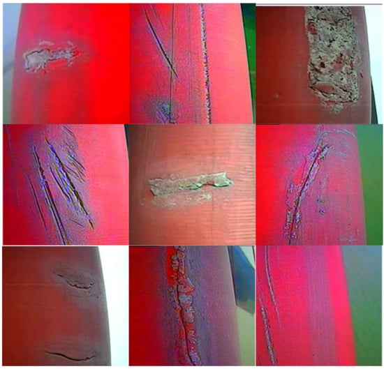
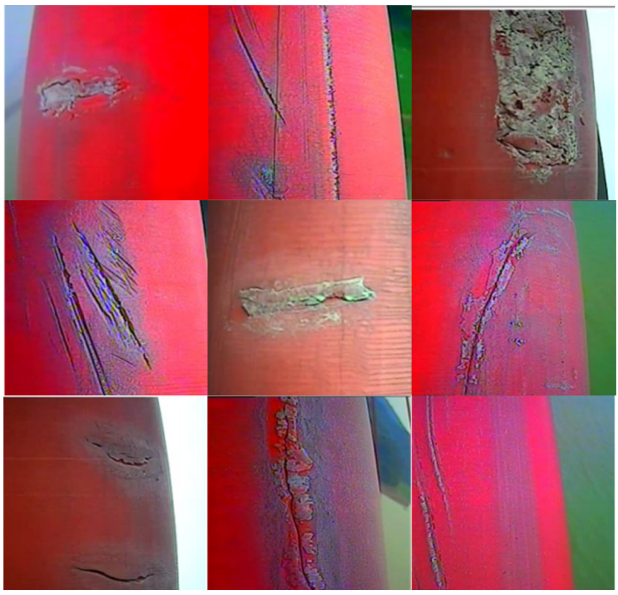
High-density polyethylene (HDPE) is the predominant material used worldwide for cable sheaths owing to its corrosion resistance, high toughness and hardness, and cost-effectiveness. In actual bridge service, however, HDPE sheaths are continuously subjected to ultraviolet (UV) radiation, fatigue loading, and chloride exposure. During photo-oxidative aging, the sheath can undergo surface embrittlement and microdefect development, while under sustained fatigue loading, it may experience localized cracking and damage (Figure 1). Because cables are exposed to the natural environment, once the sheath is breached, moisture can infiltrate the damaged region and directly contact the internal steel wires, initiating corrosion and thereby reducing the cable’s load-carrying capacity. Under long-term fatigue loading acting in conjunction with corrosion, cable performance deteriorates progressively and may ultimately culminate in wire breakage, posing a serious threat to bridge safety. Moreover, owing to the diversity of HDPE applications, resin formulations and processing routes vary, leading to pronounced differences in mechanical properties among HDPE grades tailored for different uses. Nevertheless, standards and guidelines specific to HDPE sheaths for bridge cables remain limited, and the evolution of mechanical properties under alternating multi-factor environments (e.g., UV and chloride) is still not well understood.
Figure 1.
HDPE sheath cracking.
HDPE, a thermoplastic semicrystalline polymer [1,2], exhibits mechanical properties that are sensitive to temperature [3,4,5,6], strain rate [7,8,9], and stress state [10,11,12], with additional variability arising from processing route, specimen thickness, and related manufacturing factors [13,14]. At the molecular level, HDPE comprises crystalline and amorphous phases; prior studies suggest that the crystalline phase is comparatively stable, whereas the amorphous phase is more susceptible to environmental factors [15,16,17] and is widely regarded as the primary locus of damage accumulation leading to mechanical property degradation. Extensive research has examined HDPE mechanical behavior and degradation mechanisms under single-factor exposure, namely UV radiation or chloride environments. Under UV aging and chloride attack, chain scission occurs predominantly in the amorphous phase, and the resulting short fragments can associate into micro-crystallites [18,19,20,21], thereby increasing overall crystallinity. Macroscopically, HDPE often shows concurrent changes in ductility and stiffness, reflected by reductions in yield strength and fracture strain [22,23,24]. With respect to UV exposure, Carrasco et al. [18] used Fourier-transform infrared (FTIR) spectroscopy to track the evolution of HDPE structure, chemistry, and mechanical properties under UV radiation, reporting chain scission and free-radical formation, radical recombination leading to short-chain branching, increased carbonyl content, and a rise in Young’s modulus with increasing UV-irradiation time. Li et al. [25] investigated long-term UV photo-oxidative aging under different tensile stresses and found that degradation initially increased and then decreased with applied stress, identifying a critical stress of approximately 20–25% of the yield strength. Hsueh et al. [26] characterized HDPE macroscopic and microscopic responses under UV irradiation and temperature, and, using scanning electron microscopy (SEM), attributed the increase in Young’s modulus to a hardened surface layer formed by diffusion-limited oxidation (DLO) driven by chemo-crystallization; they also reported that yield strength decreased with UV exposure duration. Lavoie et al. [27] evaluated combined thermal aging and UV irradiation in HDPE geomembranes of different thicknesses and reported a thickness-dependent aging response. Fairbrother et al. [28] applied a matrix of temperatures and UV irradiances and, combining FTIR with uniaxial tensile tests, showed that rapid embrittlement, stiffening, oxidation, and increased crystallinity occurred concurrently, with chemical changes (carbonyl and vinyl formation) exhibiting stronger temperature dependence than UV-irradiance dependence. Gong et al. [29] conducted a 24-month natural-weathering study on PE100-grade HDPE pipe and reported decreases in yield stress, elongation at break, oxidation induction time, and crystallinity with increasing exposure duration and solar irradiance, while the carbonyl index and both weight- and number-average molecular weights increased. Overall, HDPE degradation is governed by free-radical mechanisms dominated by chain scission and oxidation within the amorphous phase, together with progressive migration of interlamellar amorphous material into the crystalline phase; however, the above studies predominantly focus on UV-only (or other single-factor) aging, and the tensile response under sequential/combined UV–chloride exposures—particularly the sequence effect relevant to bridge sheaths—remains insufficiently understood.
Regarding chloride exposure, Barbosa et al. [30] performed tensile tests on poly (vinyl chloride) (PVC), polypropylene (PP), and HDPE after treatment in chlorinated media and reported that HDPE exhibited observable degradation yet largely retained its tensile strength, while ductility decreased at higher chlorine concentrations. Mikdam et al. [31] elucidated the chemical reaction mechanisms of HDPE in chloride environments and established a kinetic model for chlorine-induced degradation. Tripathi et al. [1,15] developed a morphology-based structural constitutive model for HDPE under chlorine exposure that predicted the stress–strain response over a range of crystallinities; building on this framework, they further derived a service-life model expressed as a function of molecular weight. Majewski et al. [32], through tests on HDPE films, described the migration of chain scission fragments from the amorphous phase into the crystalline phase under chlorinated conditions, concluding that chlorine-induced degradation of HDPE is fundamentally associated with changes in crystallinity. Khan et al. [33] reported that, with increasing chlorine concentration, the chemical stability of HDPE decreases, accompanied by changes in polymer-chain ordering and crystallinity. Collectively, these studies suggest that the apparent performance loss of HDPE under UV and chlorinated environments is closely linked to crystallinity evolution. Nevertheless, because resin sources and processing histories vary widely, reported results differ appreciably, and only a limited number of investigations have specifically examined HDPE used for cable sheaths. Dan et al. [34,35] measured in-service cable strains and vibration frequencies on bridges and conducted fatigue tests on HDPE sheaths based on these data; they established a crack-growth law and calibrated endurance-limit parameters for the sheath material. Liu et al. [36] performed artificial UV aging on HDPE sheath specimens held at a prescribed initial strain and, based on subsequent uniaxial tensile tests, developed a damage model for the mechanical properties. Building on these works, the mechanisms and mechanical property changes in HDPE under single-factor damage have been examined in detail; however, owing to the multivariate nature of semicrystalline polymers and the diversity of environmental stressors in bridge service, how the mechanical properties of HDPE sheaths change under realistic multi-factor environments is still not well understood. Most prior uniaxial tensile studies on HDPE sheaths have used thin-film specimens about 2 mm thick, whereas actual cable-stayed bridge sheaths are 8–15 mm thick. Accordingly, there is a need to test HDPE materials representative of cable-stayed bridge sheaths under alternating multi-stressor exposures (e.g., alternating UV–chloride conditions) to characterize how the sheath’s mechanical properties evolve under realistic in-service conditions.
In the present study, HDPE specimens were subjected to controlled pre-exposures to UV radiation and chloride environments, applied either individually or sequentially in a two-factor protocol (e.g., UV–chloride), and were subsequently tested in uniaxial tension at prescribed loading temperatures. Based on the resulting stress–strain responses and key parameters, including yield strength and elastic modulus, the evolution of the mechanical properties was systematically characterized.
2. Experiment
2.1. Test Specimens
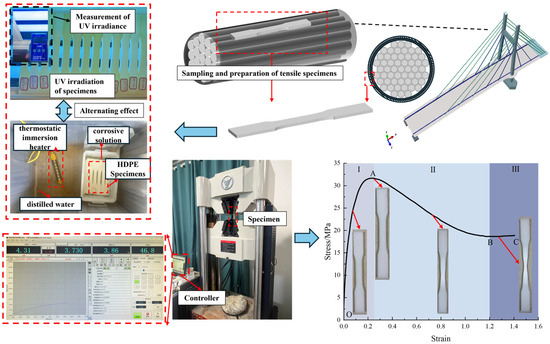
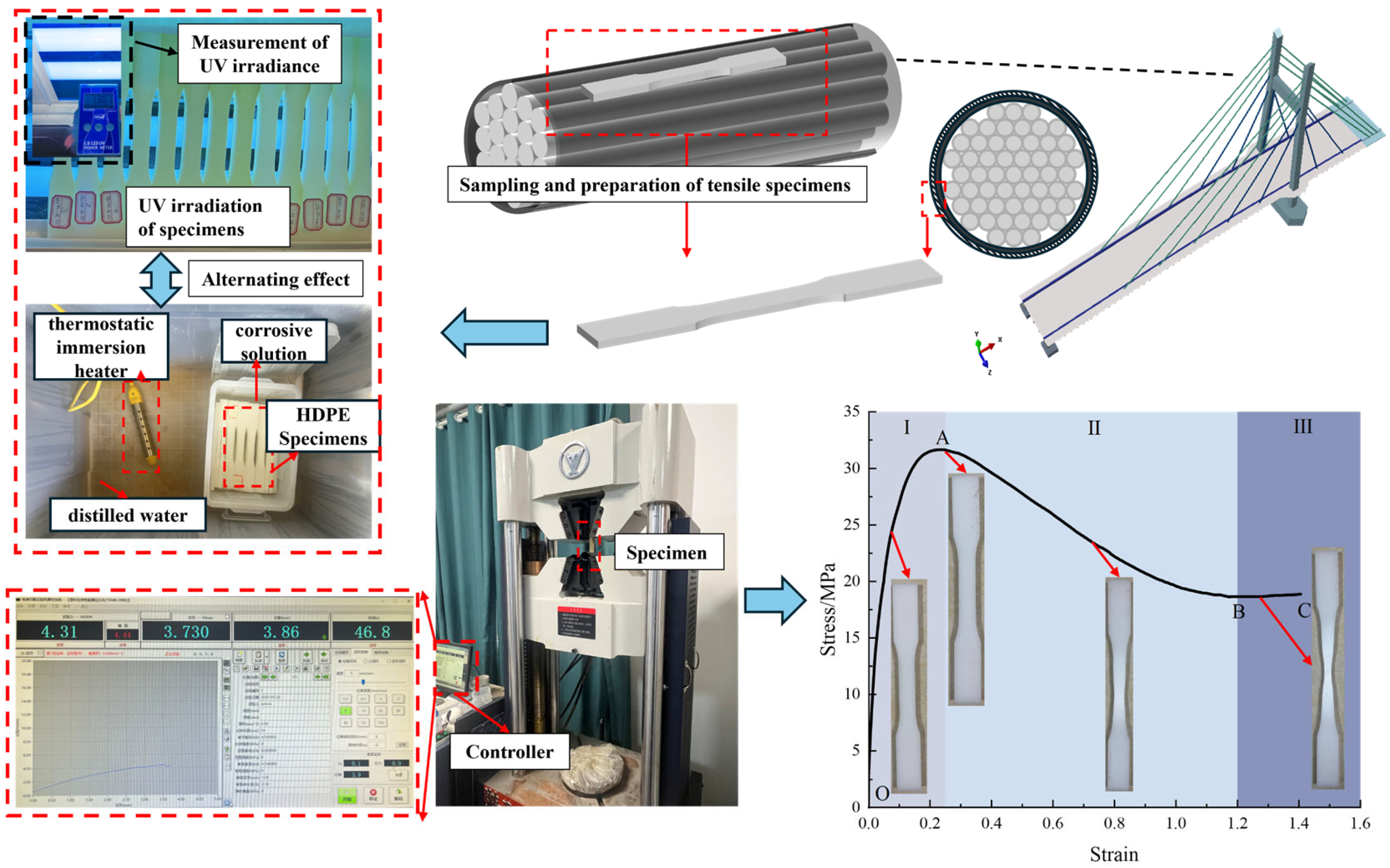
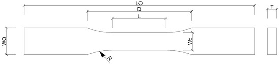
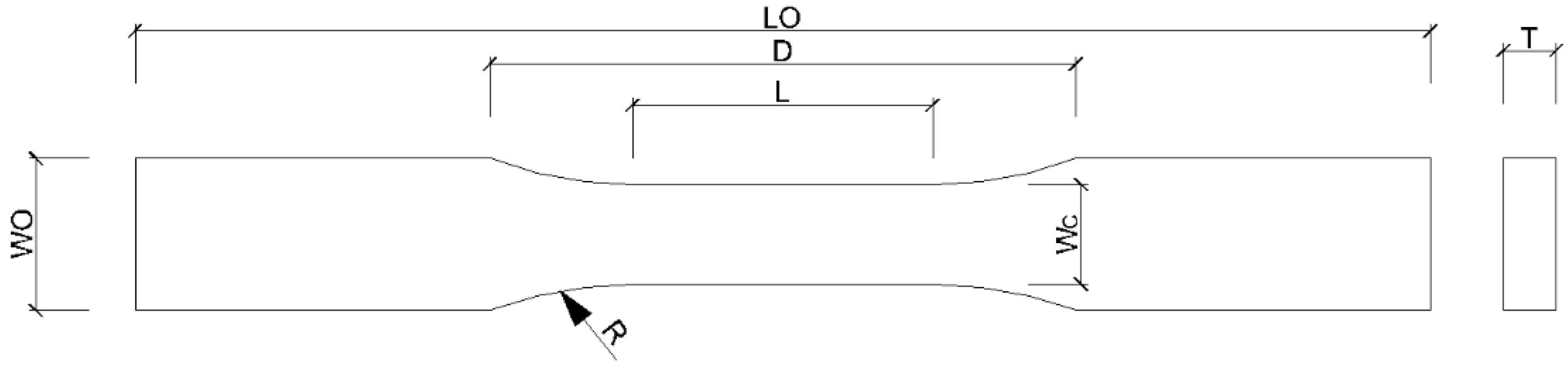
Following the HDPE sheaths’ manufacturing process: ① galvanized high-strength steel wires were laid up unidirectionally; ② the bundle was secured with high-tenacity polyester fibers; ③ a dual-layer HDPE sheath was applied by hot extrusion; and ④ it was cooled in two stages to room temperature, producing the HDPE sheath used in this study, from which the test specimens were cut. The sheath was produced by two-layer co-extrusion, in which the inner and outer layers are formed simultaneously; both layers use the same HDPE material system. Tensile specimens were cut only from the outer layer region, and thus, the tested specimens are not bilayer coupons. Specimens were cut from the HDPE sheath to the Type III (dog-bone) multipurpose dimensions specified in ASTM D638-14, Standard Test Method for Tensile Properties of Plastics [37]. The experimental procedure is shown in Figure 2, and the specimen geometry, sampling locations, and dimensions are given in Figure 3 and Table 1. The technical specifications of the HDPE used for the specimens are listed in Table 2. The material complies with the requirements for the Type-C HDPE sheet specified in CJ/T 297-2016, High-density polyethylene (HDPE) sheathing material for bridge cables [38]. It also contains an antioxidant package to enhance aging resistance.
Figure 2.
Experimental procedure.
Figure 3.
Schematic of specimen dimensions.
Table 1.
Type III (dog-bone) multipurpose standard specimen dimensions (mm).
Table 2.
Technical specifications of HDPE sheaths.
2.2. Test Conditions
Specimens were pre-exposed under single-factor conditions (UV-only or chloride-only) and under alternating UV–chloride conditions. Uniaxial tensile tests were subsequently conducted at a crosshead speed of 5 mm·min−1 in accordance with ASTM D638-14. Given the size of the test matrix, each test was terminated at 1000 s (or at fracture, whichever occurred first) to limit test duration. UV exposure tests were conducted in accordance with GB/T 16422.3-2014, Plastics—Methods of exposure to laboratory light sources—Part 3: Fluorescent UV lamps [39], using a UVA-300 accelerated weathering tester. UV irradiance at the specimen surface was measured with an LS123 UV radiometer; the irradiance was 12 W·m−2 at a central wavelength of 340 nm. The UV exposure chamber was maintained at 60 ± 3 °C and 70 ± 5% relative humidity. Chloride exposure was carried out in a custom water-bath corrosion chamber held at 50 °C. The corrosive medium was an aqueous sodium hypochlorite solution at 5%, which was replaced every 72 h to maintain a stable concentration of hypochlorite (ClO−) and chloride (Cl−) ions.
During testing, UV and chloride exposures were grouped by pre-exposure duration into seven sets (72, 144, 216, 288, 360, 432, and 504 h). Based on meteorological statistics, the loading temperature was set to −10, 20, 40, and 60 °C. For each group, three replicate specimens were tested in tension. The detailed condition matrix, including the alternating pre-exposure sequences, is given in Table 3.
Table 3.
Test conditions.
2.3. Determination of Mechanical Parameters
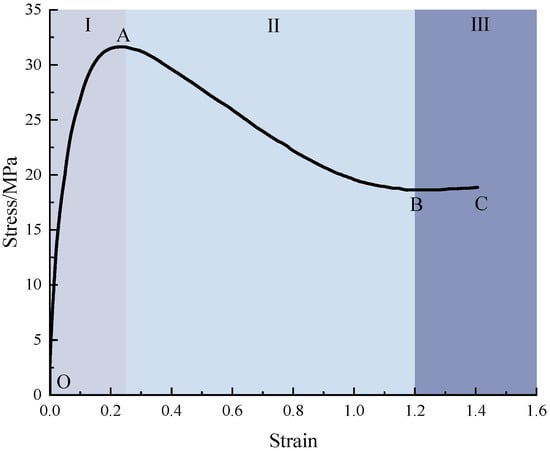
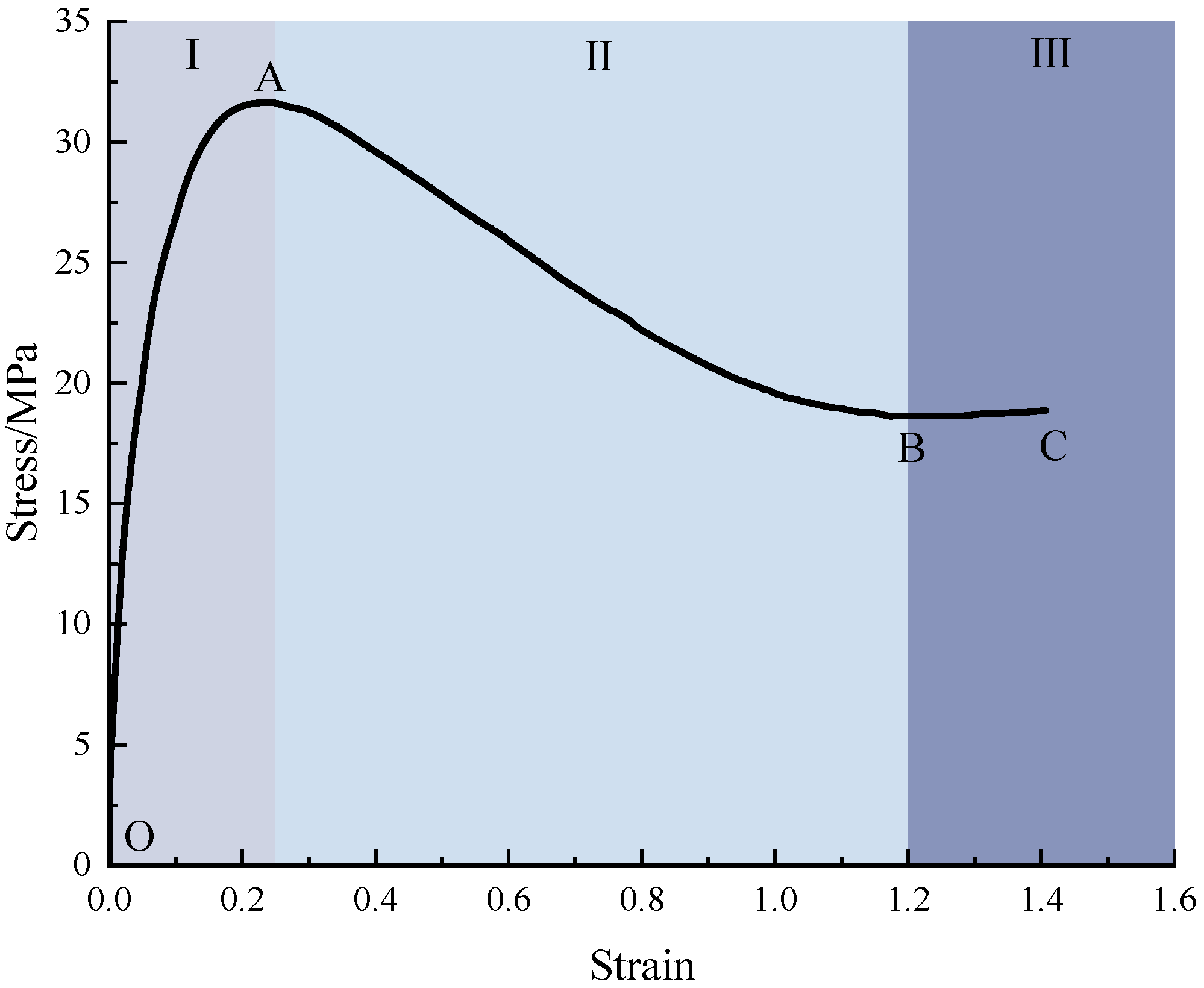
Figure 4 presents a representative tensile stress–strain curve for the HDPE specimens. Based on the characteristic response, the curve is divided into three stages (I–III): segment OA corresponds to Stage I, a nonlinear yielding regime; segment AB corresponds to Stage II, the strain-softening regime; and segment BC corresponds to Stage III, the strain-hardening regime. The engineering stress, engineering strain, and elastic modulus were determined from the following expressions:
where σ is the engineering stress of the HDPE specimen, MPa; and F is the tensile force recorded by the universal testing machine, N:
where ε is the engineering strain of the HDPE specimen, and ΔL is the displacement measured by the extensometer, mm.
Figure 4.
Typical tensile stress–strain curve of the HDPE specimen.
Because the HDPE specimens lack a distinct linear-elastic regime, the elastic modulus was determined from the yielding segment (OA) of the stress–strain curve and defined as the O-A secant modulus [36]:
where E is the elastic modulus of the HDPE specimen, MPa; is the engineering stress at point A, MPa; and is the engineering strain at point A.
3. Test Results
3.1. Single-Factor Exposure
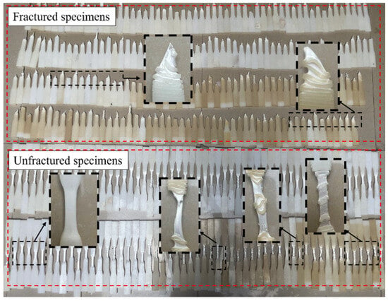
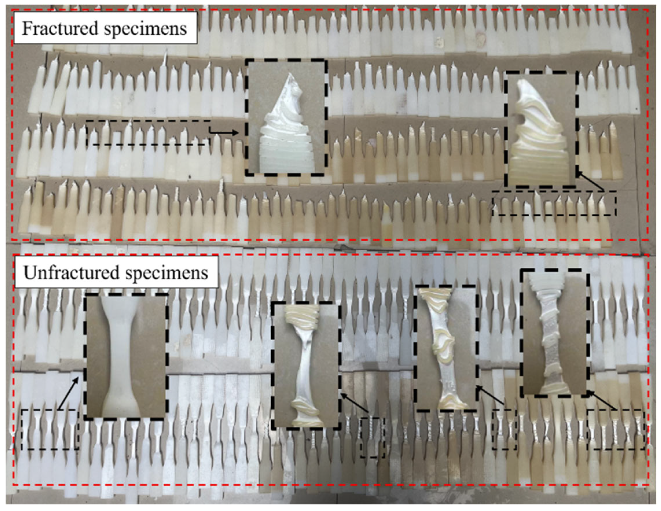
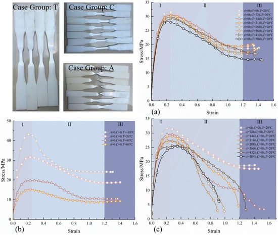
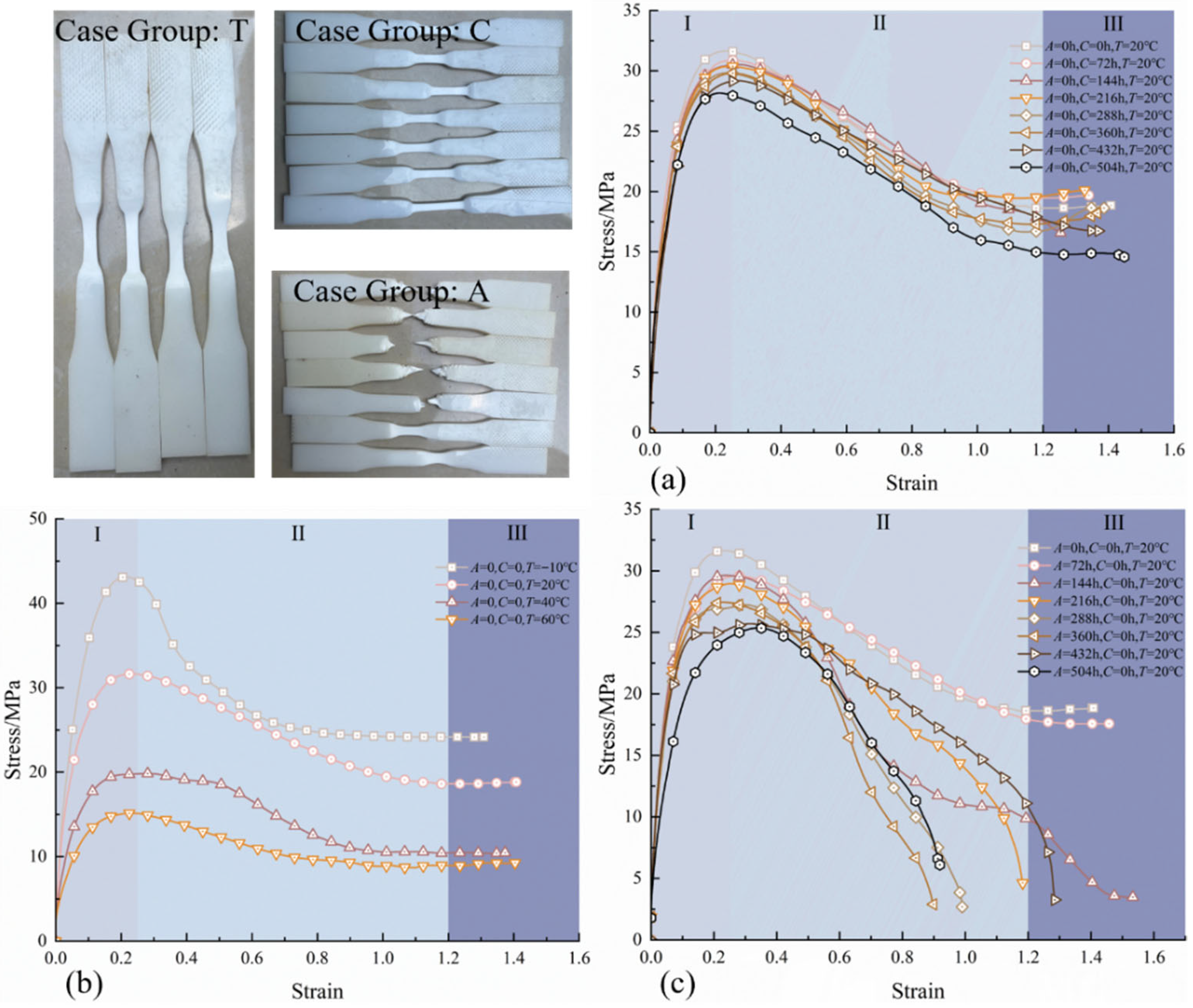
All specimens after tensile testing are shown in Figure 5. At a loading temperature of 20 °C, the stress–strain curves of groups A, C, and T are shown in Figure 6, where the Stage I–III regions are delineated using the unexposed specimen at 20 °C as the reference. Under UV-only exposure, the specimens exhibited a more pronounced degradation of mechanical properties, accompanied by alterations in the strain-hardening segment of the curve. With increasing pre-exposure duration (72–504 h), the yield strength decreased relative to the unexposed value by 6.48%, 6.30%, 8.49%, 13.89%, 13.19%, 18.74%, and 19.82%, respectively. Taking 288 h as a demarcation, the reduction before 288 h was relatively modest—consistent with incomplete chain scission—whereas beyond 288 h, UV aging led to increased bond scission and the formation of microcracks, producing a larger drop in yield strength. After UV exposure, the strain at the onset of the hardening stage shifted to lower values; in some cases, specimens fractured within the softening stage and did not enter the hardening stage at all. In contrast to UV-only exposure, specimens subjected to chloride-only pre-exposure exhibited changes primarily in yield strength. Relative to the unexposed baseline, the reductions with increasing pre-exposure duration were 2.36%, 3.53%, 3.96%, 5.74%, 5.76%, 7.74%, and 10.98—clearly smaller than for UV-only exposure. The strain at the onset of the hardening stage exhibited no appreciable shift, remaining at 1.2. Because HDPE is temperature-sensitive, elevated temperature increases molecular mobility and modifies the mechanical response. As shown in Figure 6c, the yield strength at 20, 40, and 60 °C decreased by 26.65%, 53.99%, and 64.89%, respectively, relative to −10 °C. The onset of the strain-hardening stage occurred earlier at −10, 40, and 60 °C than at 20 °C (i.e., a lower transition strain). After rinsing the specimens with deionized water and air-drying until no surface moisture remained, the post-tensile surface appearance was examined: relative to the unexposed specimens, group C and group T showed no obvious color change and remained white, whereas group A exhibited progressive yellowing with increasing UV exposure duration.
Figure 5.
Specimens after tensile testing.
Figure 6.
Stress–strain curves of specimens under single-factor exposure: (a) Group C; (b) Group T; (c) Group A.
3.2. Alternating UV–Chloride Exposure at Different Loading Temperatures
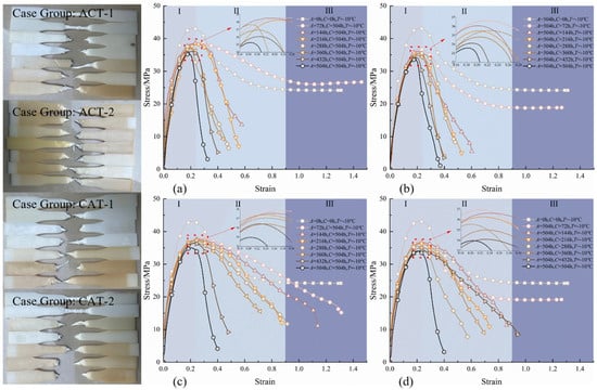
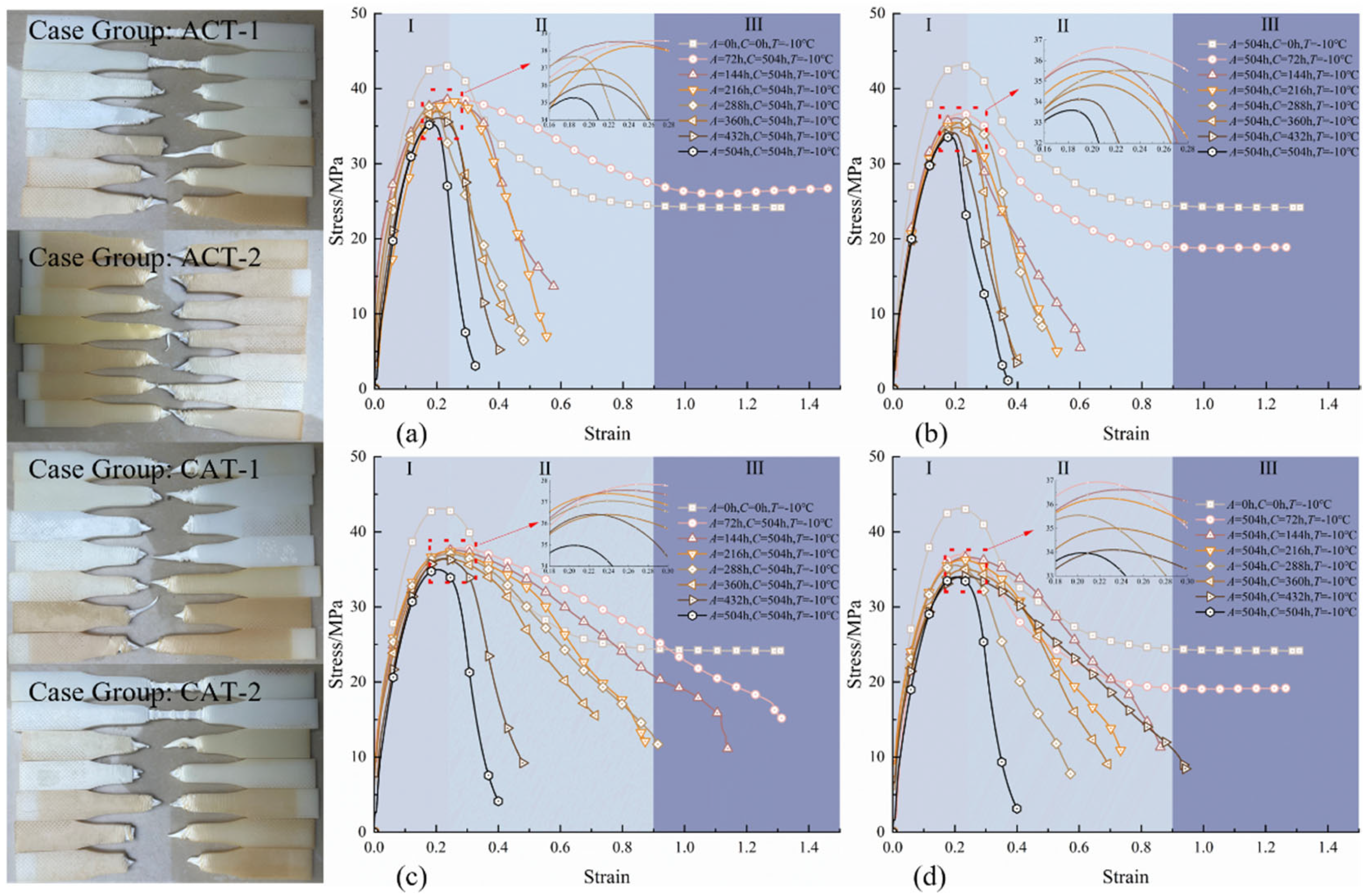
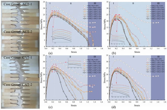
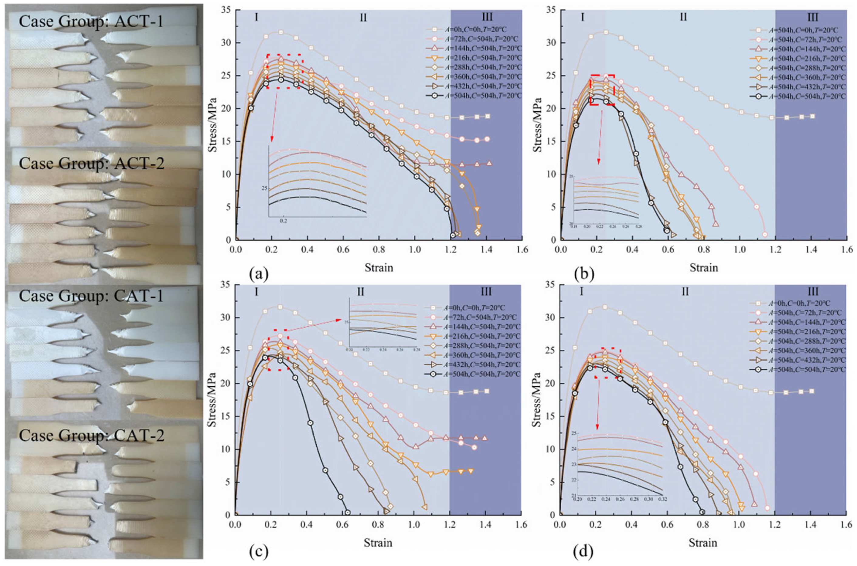
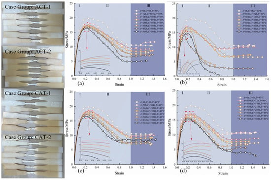
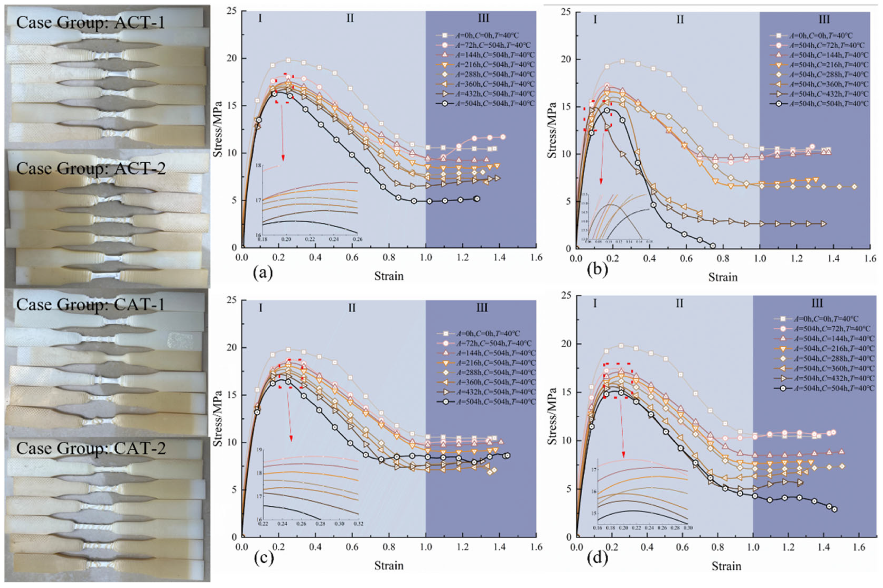
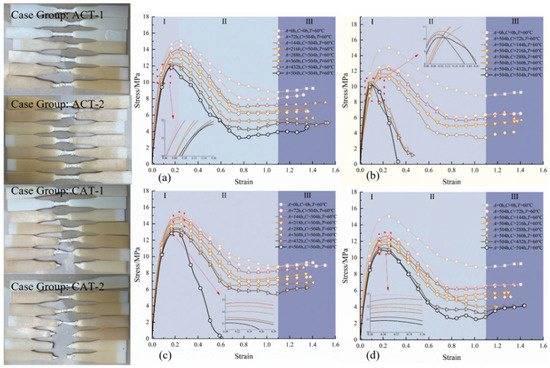
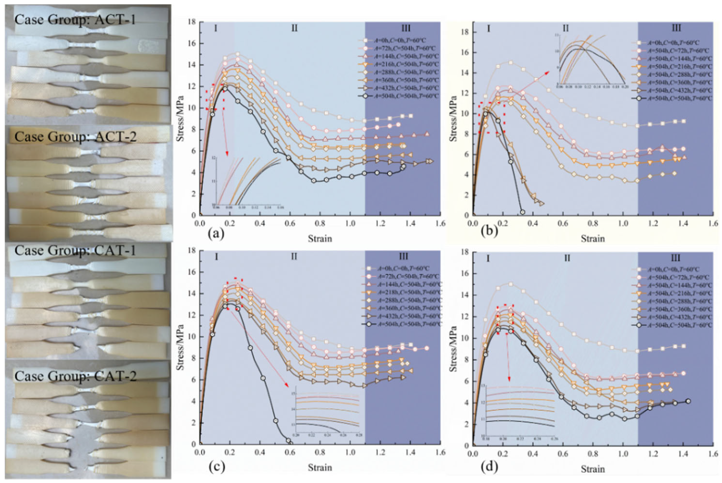
The stress–strain curves of HDPE specimens under alternating UV–chloride exposures at different loading temperatures are shown in Figure 7, Figure 8, Figure 9 and Figure 10. At −10 °C (Figure 7), the maximum reductions in yield strength relative to the −10 °C unexposed baseline were 18.90% for CAT-1, 21.22% for CAT-2, 22.09% for ACT-2, and 18.17% for ACT-1. These results indicate that UV-first pre-exposure produces a greater reduction in yield strength than chloride-first pre-exposure, and this difference depends on UV duration: the longer the prior UV exposure, the lower the yield strength. At −10 °C, UV-first specimens fractured earlier, while chloride-first specimens showed higher fracture strain and an earlier onset of strain softening. At a loading temperature of 20 °C (Figure 8), the maximum reductions in yield strength relative to the 20 °C baseline were 23.76% for CAT-1, 28.76% for CAT-2, 31.97% for ACT-2, and 22.94% for ACT-1, again confirming a clear sequence effect: UV-first pre-exposure causes greater deterioration than chloride-first. At 40 °C (Figure 9), the corresponding maximum reductions were 16.16% for CAT-1, 23.69% for CAT-2, 25.81% for ACT-2, and 17.15% for ACT-1. At 60 °C (Figure 10), they were 13.28% for CAT-1, 27.52% for CAT-2, 32.71% for ACT-2, and 21.68% for ACT-1. Across all loading temperatures, UV-first pre-exposure consistently produced the largest loss in yield strength, with ACT-2 exhibiting the most severe degradation at each temperature.
Figure 7.
Stress–strain curves of HDPE specimens under alternating UV–chloride exposure at a loading temperature of −10 °C: (a) ACT-1, (b) ACT-2, (c) CAT-1, and (d) CAT-2.
Figure 8.
Stress–strain curves of HDPE specimens under alternating UV–chloride exposure at a loading temperature of 20 °C: (a) ACT-1, (b) ACT-2, (c) CAT-1, and (d) CAT-2.
Figure 9.
Stress–strain curves of HDPE specimens under alternating UV–chloride exposure at a loading temperature of 40 °C: (a) ACT-1, (b) ACT-2, (c) CAT-1, and (d) CAT-2.
Figure 10.
Stress–strain curves of HDPE specimens under alternating UV–chloride exposure at a loading temperature of 60 °C: (a) ACT-1, (b) ACT-2, (c) CAT-1, and (d) CAT-2.
Across all loading temperatures, visual inspection of specimen surfaces showed the deepest yellowing for group ACT-2, followed by CAT-2, ACT-1, and CAT-1. UV exposure markedly altered color, and the extent of yellowing increased with UV duration. Subsequent chloride exposure further intensified the yellowing. When chloride preceded UV, as in groups CAT-1 and CAT-2, the color change was greater than in group A and group C, but remained less severe than in the UV-first sequences ACT-1 and ACT-2.
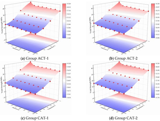
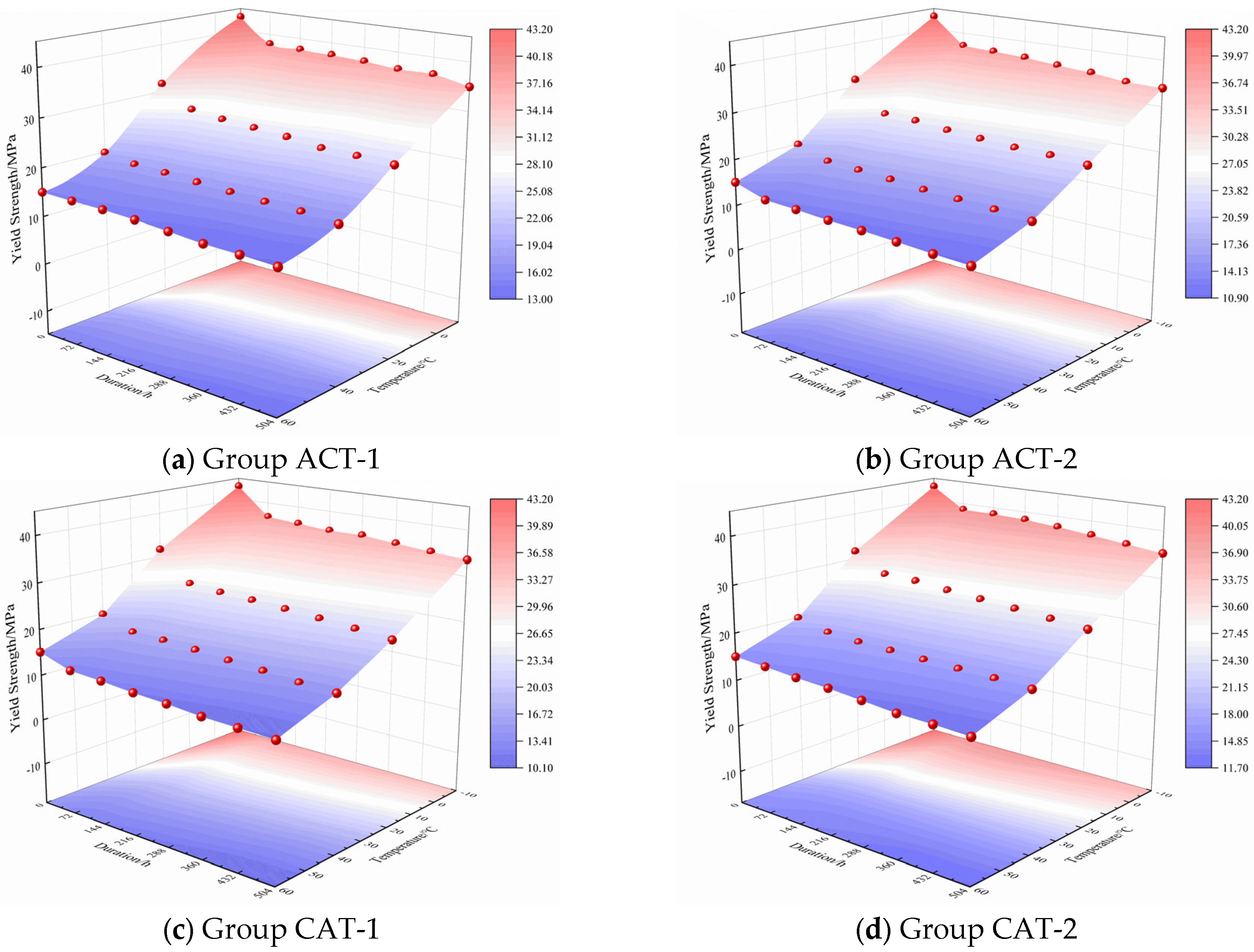
Figure 11 shows three-dimensional response surfaces of HDPE yield strength versus pre-exposure duration and loading temperature for the different pre-exposure sequences. Overall, the yield strength decreases monotonically with increasing pre-exposure duration, confirming progressive mechanical deterioration under combined UV–chloride action. Meanwhile, with increasing loading temperature, the surface shifts downward, and the duration-axis decay slope becomes slightly smaller at higher temperatures. A clear order effect emerges: UV → chloride gives the lowest yield strength, and chloride → UV retains the most.
Figure 11.
Response surface of specimen yield strength.
We performed a graded statistical analysis of specimen color. The grading criteria and the corresponding statistics are shown in Table 4 and Table 5
Table 4.
Color grading criteria.
Table 5.
Color statistics results.
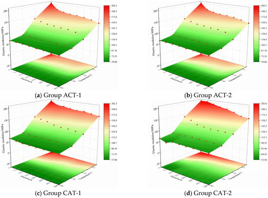
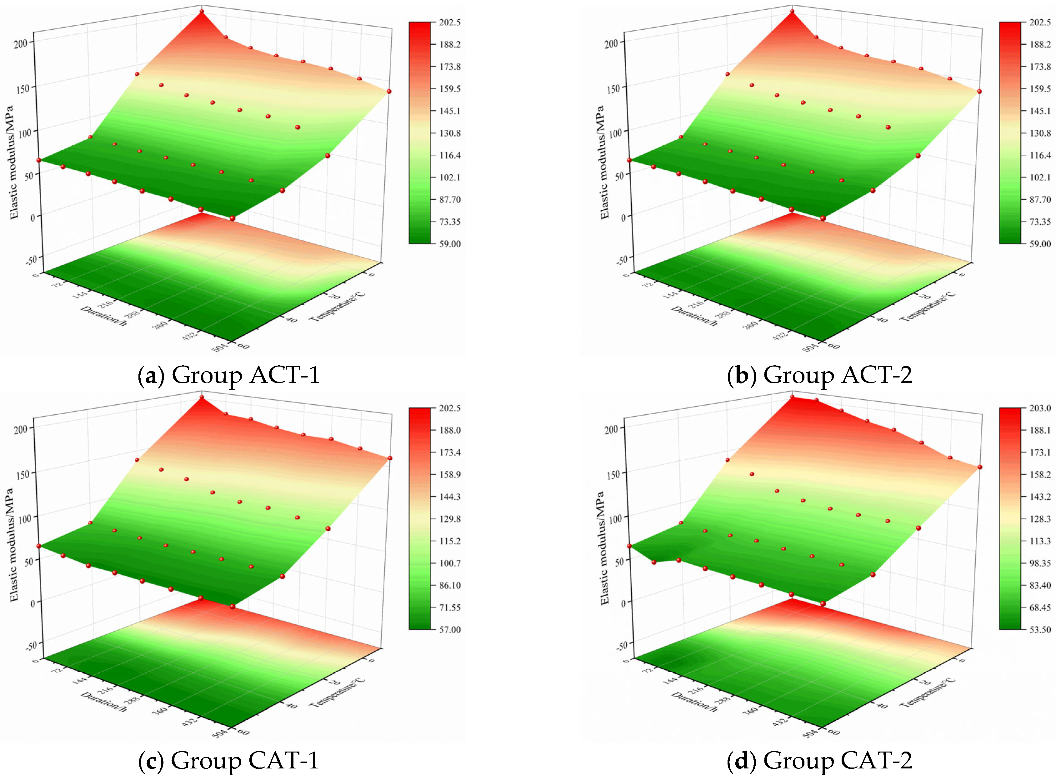
Figure 12 shows the three-dimensional response surfaces of the elastic modulus as functions of pre-exposure duration and loading temperature. For all sequences, the elastic modulus decreases monotonically with increasing pre-exposure duration, with an average temporal gradient of approximately −0.30 MPa·h−1—about four times the time sensitivity of the yield strength—indicating that the modulus is more sensitive to chemical damage. Superimposed on this trend, the modulus increases with loading temperature at roughly −1.1 MPa·°C−1. Notably, this temperature-induced increase does not materially offset the time-driven decay, indicating that modulus deterioration is governed primarily by chemical aging rather than viscoelastic temperature effects.
Figure 12.
Response surface of specimen elastic modulus.
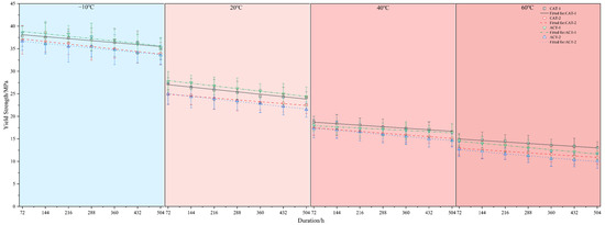
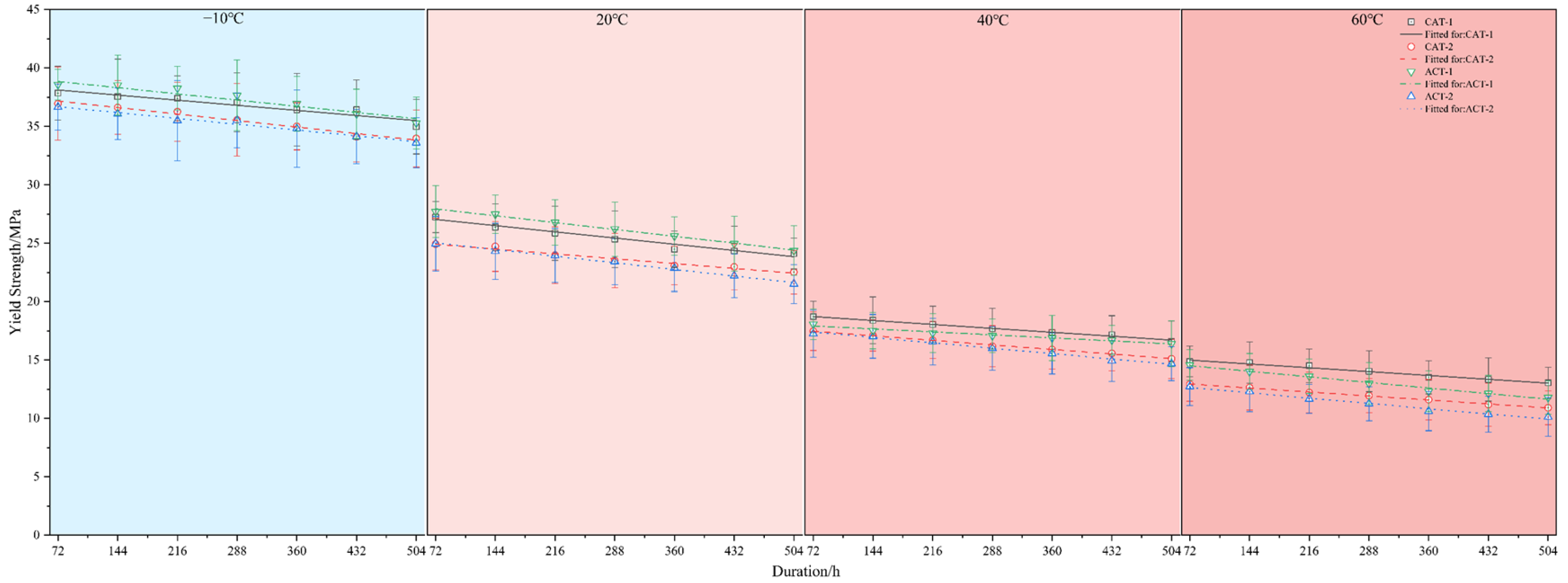
Figure 13 and Figure 14 show the variations in yield strength and elastic modulus across loading temperatures. The yield strength decreases with increasing pre-exposure duration, and the slope is roughly similar as the loading temperature rises from −10 to 60 °C. Among the alternating sequences, ACT-2 exhibits the lowest yield strength, followed by CAT-2; at −10 and 20 °C, ACT-1 exceeds CAT-1, whereas at 40 and 60 °C, the trend reverses.
Figure 13.
Evolution of specimen yield strength with pre-exposure duration.
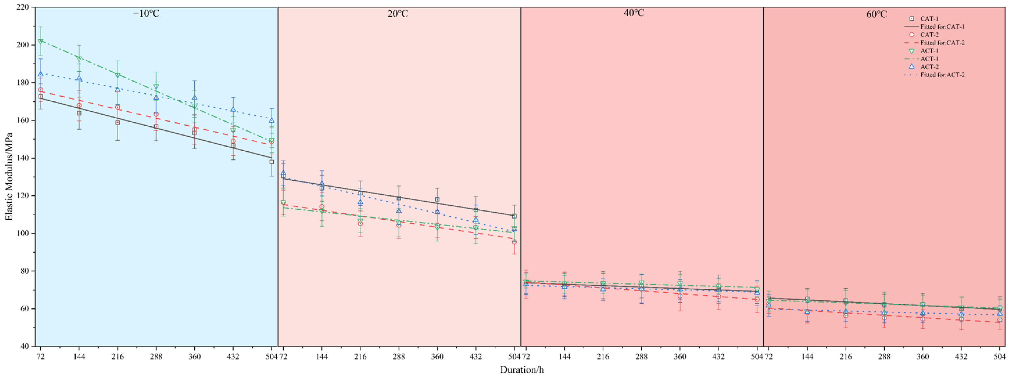
Figure 14.
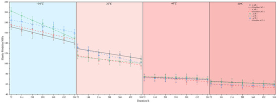
Evolution of specimen elastic modulus with pre-exposure duration.
The elastic modulus declines monotonically with pre-exposure duration, and with increasing loading temperature, the entire curve shifts downward while the slope becomes smaller in magnitude. The sequence effect shows a pronounced temperature dependence: at −10 °C, the ordering is ACT-1 > ACT-2 > CAT-2 > CAT-1; at 20 °C, CAT-1 lies at a higher level, while CAT-2 and ACT-1 are relatively lower and close to each other; by 40 °C, the differences narrow markedly; and at 60 °C, CAT-1 and ACT-1 are approximately the same.
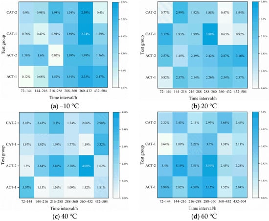
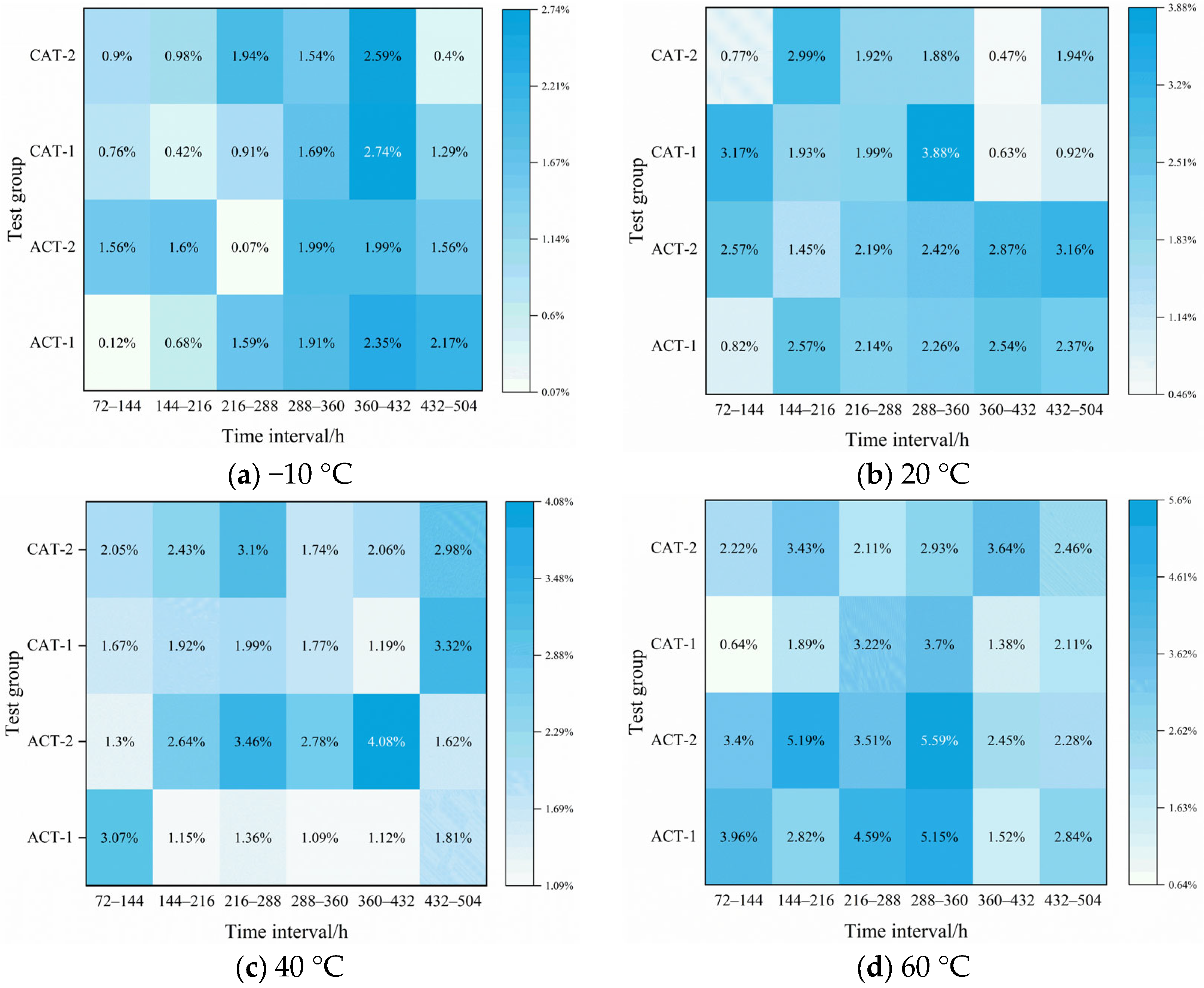
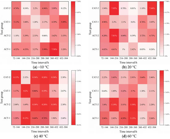
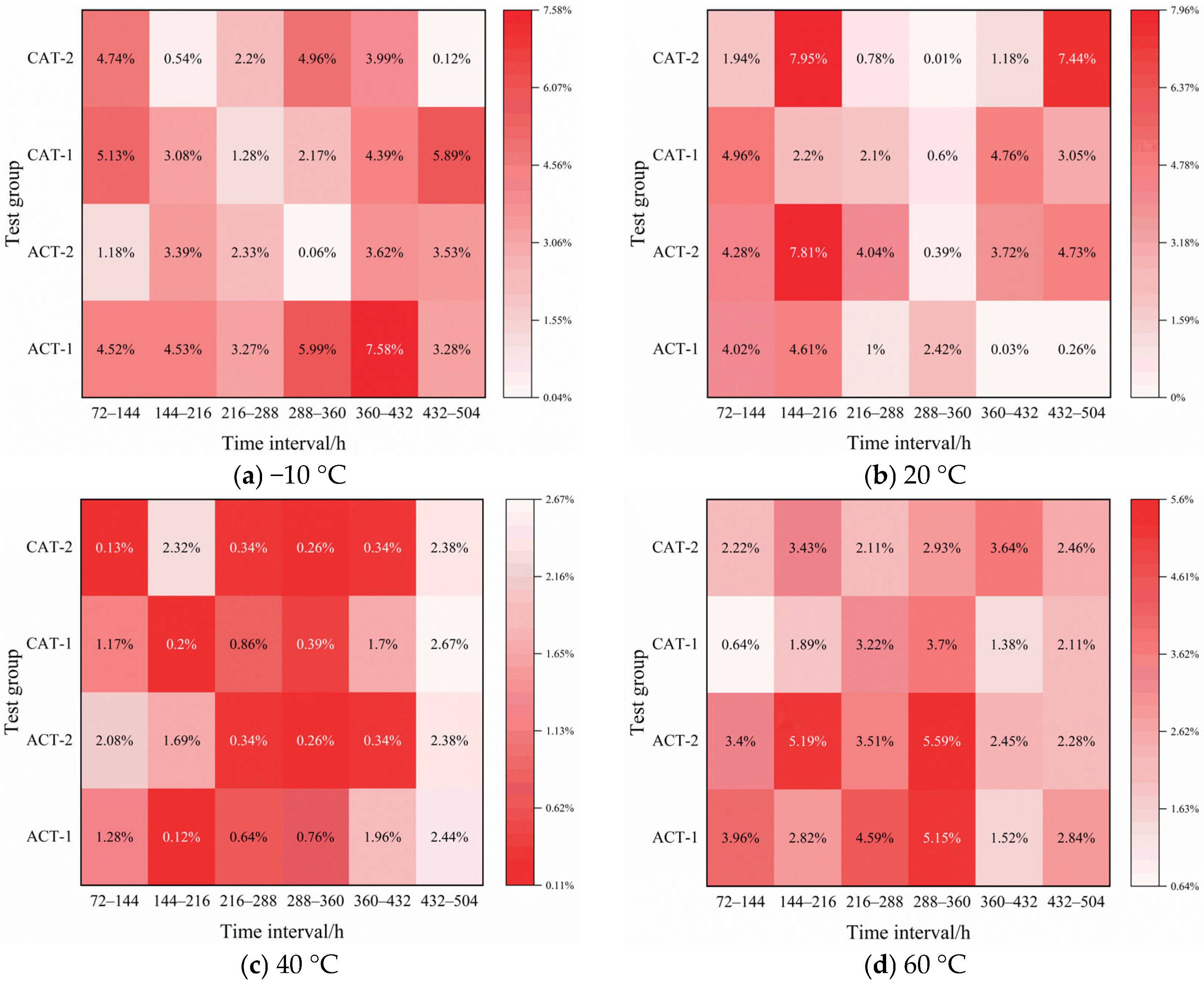
Figure 15 and Figure 16 depict stepwise decreases in yield strength and elastic modulus over consecutive 72 h time intervals. For comparison, Gong et al. [29] reported a maximum 8.3% decrease in HDPE yield strength under UV-only aging. In the present alternating-exposure tests, the per-interval reduction in yield strength at −10 °C ranged from 0.07% in ACT-2 to 2.74% in CAT-1; at 20 °C, it ranged from 0.47% in CAT-2 to 3.88% in CAT-1; at 40 °C, it ranged from 1.09% in ACT-1 to 4.08% in ACT-2; and at 60 °C, it ranged from 0.64% in CAT-1 to 5.59% in ACT-2. In terms of temporal distribution, higher temperatures (40–60 °C) tended to produce a belt of peaks in the mid-stage interval (216–360 h), whereas at −10 °C, the reductions grew progressively toward the late stage (360–504 h); under UV → chloride sequences, the high-decrement segments were more concentrated, whereas under chloride → UV, the evolution was comparatively smooth. The elastic modulus showed positive per-interval decreases throughout, but with a distinct time–temperature signature from that of yield strength: it was more sensitive at lower temperatures and in the early stages of pre-exposure and tended to converge at higher temperatures [40,41]. The per-72 h modulus reductions ranged, at −10 °C, from 0.06% for ACT-2 to 7.58% for ACT-1; at 20 °C, from 0.01% for CAT-2 to 7.95% for CAT-2; at 40 °C, from 0.12% for ACT-1 to 2.67% for CAT-1; and at 60 °C, from 0.04% for CAT-1 to 7.33% for CAT-2. Overall, spikes in modulus reduction were more likely to occur at −10–20 °C during early and late pre-exposure intervals, whereas at 40–60 °C, the stepwise decreases rapidly converged to low amplitudes across most intervals. At higher loading temperatures, the sequence effect diminishes in magnitude but remains discernible. Overall, the Figures indicate that yield strength exhibits amplified per-interval reductions with increasing temperature and a tendency for mid-stage clustering, whereas the elastic modulus is more sensitive at low temperatures, converges at high temperatures, and shows a propensity for early- and late-stage spikes.
Figure 15.
Heat map of yield-strength damage.
Figure 16.
Heat map of elastic modulus damage.
Under combined UV–chloride action, the HDPE specimens exhibit a pronounced time–temperature-coupled deterioration. For identical pre-exposure increments and across the four pre-exposure sequences, the mechanical properties of the HDPE sheaths degrade cumulatively with pre-exposure duration: the yield strength decreases monotonically at all loading temperatures, and the per-interval drop grows with temperature, approximately 0–2.7% at −10 °C versus 2–5% at 60 °C, indicating that the loading temperature amplifies the apparent manifestation of damage in the measured strength. The elastic modulus was markedly more sensitive at low temperature: at −10 °C, the reduction was 4–8%, whereas at 60 °C, it was mostly 0–2%, indicating that the temperature sensitivity of the modulus response was not synchronized with that of the yield strength. The pre-exposure sequence effect was consistent across all temperatures: UV → chloride produced the largest cumulative reductions, chloride → UV yielded the smallest, and ACT-1 and CAT-1 lay in between, providing evidence of a synergistic accelerating effect of combined UV–chloride action.
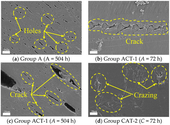
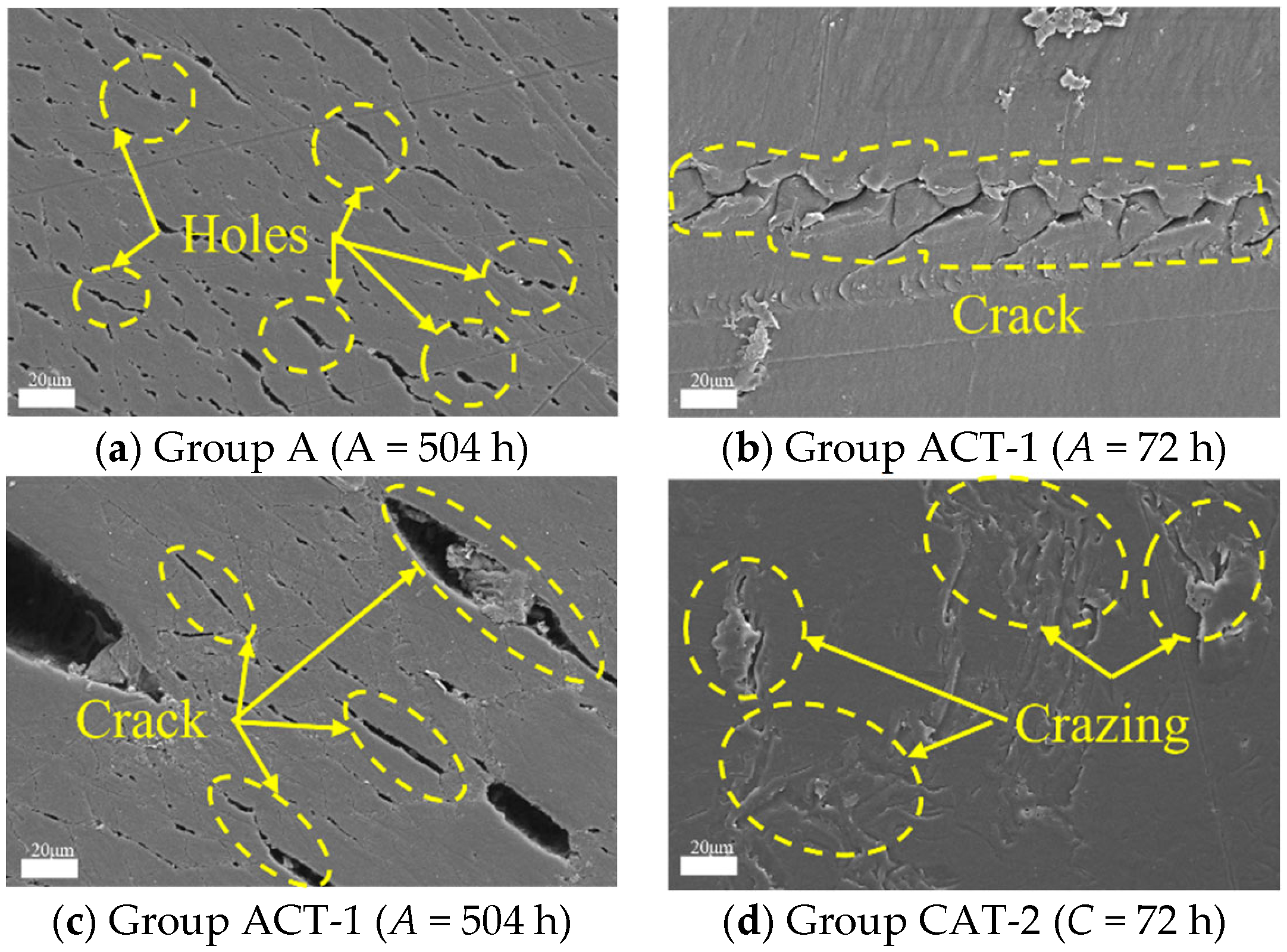
The surface SEM images of the specimens are shown in Figure 17. UV exposure first induces photo-oxidation and chain scission in the near-surface layer, making the formation of surface microdefects more likely. This is a typical pathway by which polymer photo-oxidation reduces molecular weight and deteriorates mechanical performance. Once UV has generated surface voids, the chloride-containing medium can penetrate through these voids, thereby accelerating microvoid growth and coalescence, suppressing the fibrillated energy-dissipation mechanism, and ultimately promoting the transition observed in SEM from ductile fibrillated fracture to brittle cleavage-dominated fracture.
Figure 17.
Specimen surface SEM images.
4. Conclusions
This study focused on HDPE sheaths. Custom sheaths were manufactured in accordance with the industrial production process, subjected to single-factor pre-exposures (UV or chloride) and alternating two-factor UV–chloride pre-exposures, and then tested in uniaxial tension. Based on the test results, the following conclusions are drawn:
- The mechanical properties of HDPE sheaths deteriorate progressively under UV and chloride exposure, both as single factors and in sequential two-factor protocols. The results show a monotonic decline in yield strength with increasing pre-exposure duration, accompanied by a reduction in elastic modulus. Notably, sequential UV–chloride exposure produces substantially greater degradation than either factor alone, indicating a super-additive (synergistic) interaction. At the same loading temperature and a pre-exposure duration of 504 h, the maximum reductions in yield strength and elastic modulus were 19.81% and 46.21% for UV-only, 10.97% and 22.00% for chloride-only, 31.97% and 26.24% for UV → chloride, and 28.76% and 21.27% for chloride → UV.
- The apparent severity of post-exposure mechanical deterioration is strongly governed by the loading temperature. The material response varies markedly with test temperature: higher temperatures amplify the pre-exposure-induced loss of yield strength, whereas lower temperatures accentuate the reduction in elastic modulus. Consequently, the test temperature can either amplify or mask the effects of prior aging on HDPE mechanical properties; evaluating sheath degradation at a single temperature may therefore lead to biased or misleading conclusions.
- Relative to the chloride → UV sequence, the UV → chloride sequence produces larger losses in mechanical properties: the reductions in yield strength and elongation at break exceed the simple sum of the two single-factor effects, indicating a super-additive interaction. Targeted mitigation of this sequence effect—via enhanced protection and material modification—is recommended to ensure the long-term serviceability of HDPE sheaths.
- Chemical and surface characterization methods were not included in this study; therefore, the mechanistic interpretation of oxidation and surface activation is supported primarily by the controlled exposure design, the temperature-dependent tensile response, and SEM-based microdamage evolution, and should be regarded as an engineering-level interpretation rather than direct chemical proof.
- From an engineering perspective, the pronounced sequence sensitivity in the alternating UVA–chlorine environment indicates that bridge HDPE sheaths should prioritize resistance to UV-first surface damage, and maintenance should focus on periodic inspection and renewal of sun-exposed surfaces to suppress surface void accumulation that can accelerate subsequent chlorine/salt-assisted embrittlement.
Author Contributions
Conceptualization, J.W. and Q.M.; Investigation, Q.Z. and Q.M.; Resources, H.D., Q.M. and K.Z.; Data curation, J.W., H.D. and K.Z.; Writing—original draft, H.D. and Q.M.; Writing—review & editing, Q.Z. and Q.M.; Supervision, Q.Z. All authors have read and agreed to the published version of the manuscript.
Funding
This work was supported by the Natural Science Foundation of Jiangxi Province (20252BAC250116), the Tianjin Beijing–Tianjin–Hebei Collaborative Innovation Funding Project (25YFXTHZ00560), Research Project of Jiangxi Provincial Communications Investment Group Co., Ltd. (No. 2023JT0007), the Natural Science Foundation of Tianjin (23JCZDJC00510).
Data Availability Statement
Data will be made available on request.
Conflicts of Interest
Author Jing Wang was employed by the company Jiangxi Ganyue Expressway Co., Ltd. and Tianjin Saida Weiye Co., Ltd. Author Qingling Meng was employed by the company Jiangxi Ganyue Expressway Co., Ltd. Author Ke Zhang was employed by the company Beijing Urban Construction Group Co., Ltd. The remaining authors declare that the research was conducted in the absence of any commercial or financial relationships that could be construed as a potential conflict of interest.
References
- Tripathi, A.; Mantell, S.; Le, J.-L. Chemo-mechanical modeling of static fatigue of high density polyethylene in bleach solution. Int. J. Solids Struct. 2021, 217–218, 90–105. [Google Scholar] [CrossRef] [Scilit]
- Ghanadi, M.; Padhye, L.P. Revealing the long-term impact of photodegradation and fragmentation on HDPE in the marine environment: Origins of microplastics and dissolved organics. J. Hazard. Mater. 2024, 465, 133509. [Google Scholar] [CrossRef] [Scilit] [PubMed]
- Shahin, A.; Barsoum, I.; Islam, M.D. Constitutive model calibration of the time and temperature-dependent behavior of high density polyethylene. Polym. Test. 2020, 91, 106800. [Google Scholar] [CrossRef] [Scilit]
- Merah, N.; Saghir, F.; Khan, Z.; Bazoune, A. Effect of temperature on tensile properties of HDPE pipe material. Plast. Rubber Compos. 2006, 35, 226–230. [Google Scholar] [CrossRef] [Scilit]
- Barba, D.; Arias, A.; Garcia-Gonzalez, D. Temperature and strain rate dependences on hardening and softening behaviours in semi-crystalline polymers: Application to PEEK. Int. J. Solids Struct. 2020, 182–183, 205–217. [Google Scholar] [CrossRef] [Scilit]
- Zhang, W.; Li, J.; Li, H.; Jiang, S.; An, L. Temperature dependence of deformation behavior of poly(butylene terephthalate). Polymer 2018, 143, 309–315. [Google Scholar] [CrossRef] [Scilit]
- Qi, Z.; Hu, N.; Li, G.; Zeng, D.; Su, X. Constitutive modeling for the elastic-viscoplastic behavior of high density polyethylene under cyclic loading. Int. J. Plast. 2019, 113, 125–144. [Google Scholar] [CrossRef] [Scilit]
- Reis, J.M.L.; Pacheco, L.J.; Da Costa Mattos, H.S. Tensile behavior of post-consumer recycled high-density polyethylene at different strain rates. Polym. Test. 2013, 32, 338–342. [Google Scholar] [CrossRef] [Scilit]
- Gao, B.; Luo, M.; Lin, K.; Ding, J.; Liu, B. Fatigue crack growth and slow crack growth of HDPE pipes under internal pressure and flat plate compression. Int. J. Press. Vessel. Pip. 2024, 208, 105155. [Google Scholar] [CrossRef] [Scilit]
- Hachour, K.; Zaïri, F.; Naït-Abdelaziz, M.; Gloaguen, J.M.; Aberkane, M.; Lefebvre, J.M. Experiments and modeling of high-crystalline polyethylene yielding under different stress states. Int. J. Plast. 2014, 54, 1–18. [Google Scholar] [CrossRef] [Scilit]
- Ayoub, G.; Zaïri, F.; Naït-Abdelaziz, M.; Gloaguen, J.M. Modelling large deformation behaviour under loading–unloading of semicrystalline polymers: Application to a high density polyethylene. Int. J. Plast. 2010, 26, 329–347. [Google Scholar] [CrossRef] [Scilit]
- Pastrnak, A.; Henriquez, A.; La Saponara, V. Parametric study for tensile properties of molded high-density polyethylene for applications in additive manufacturing and sustainable designs. J. Appl. Polym. Sci. 2020, 137, 49283. [Google Scholar] [CrossRef] [Scilit]
- Amjadi, M.; Fatemi, A. Tensile Behavior of High-Density Polyethylene Including the Effects of Processing Technique, Thickness, Temperature, and Strain Rate. Polymers 2020, 12, 1857. [Google Scholar] [CrossRef] [Scilit] [PubMed]
- Hasan, O.A.; Boyce, M.C. A constitutive model for the nonlinear viscoelastic viscoplastic behavior of glassy polymers. Polym. Eng. Sci. 1995, 35, 331–344. [Google Scholar] [CrossRef] [Scilit]
- Tripathi, A.; Mantell, S.; Le, J.-L. A morphology based constitutive model for high density polyethylene. Mech. Mater. 2019, 137, 103091. [Google Scholar] [CrossRef] [Scilit]
- Wismans, M.; van Dommelen, J.A.W.; Engels, T.A.P.; van Breemen, L.C.A. A macroscopic viscoelastic viscoplastic constitutive model for porous polymers under multiaxial loading conditions. J. Mech. Phys. Solids 2024, 183, 105499. [Google Scholar] [CrossRef] [Scilit]
- Ghorbel, E. A viscoplastic constitutive model for polymeric materials. Int. J. Plast. 2008, 24, 2032–2058. [Google Scholar] [CrossRef] [Scilit]
- Carrasco, F.; Pagès, P.; Pascual, S.; Colom, X. Artificial aging of high-density polyethylene by ultraviolet irradiation. Eur. Polym. J. 2001, 37, 1457–1464. [Google Scholar] [CrossRef] [Scilit]
- Wu, S.; Zhang, J.; Xu, X. Studies on high density polyethylene (HDPE) functionalized by ultraviolet irradiation and its application. Polym. Int. 2003, 52, 1527–1530. [Google Scholar] [CrossRef] [Scilit]
- Fu, Q.; Men, Y.; Strobl, G. Understanding of the tensile deformation in HDPE/LDPE blends based on their crystal structure and phase morphology. Polymer 2003, 44, 1927–1933. [Google Scholar] [CrossRef] [Scilit]
- Drozdov, A.D.; Christiansen, J.D. Thermo-viscoelastic and viscoplastic behavior of high-density polyethylene. Int. J. Solids Struct. 2008, 45, 4274–4288. [Google Scholar] [CrossRef] [Scilit]
- Khelif, R.; Chateauneuf, A.; Chaoui, K. Statistical analysis of HDPE fatigue lifetime. Meccanica 2008, 43, 567–576. [Google Scholar] [CrossRef] [Scilit]
- Lu, Y.; Yang, W.; Zhang, K.; Yang, M. Stress relaxation behavior of high density polyethylene (HDPE) articles molded by gas-assisted injection molding. Polym. Test. 2010, 29, 866–871. [Google Scholar] [CrossRef] [Scilit]
- Wu, S.; Xu, X. Structure and properties of ultraviolet-irradiated high density polyethylene at different environmental temperatures. J. Appl. Polym. Sci. 2003, 89, 2966–2969. [Google Scholar] [CrossRef] [Scilit]
- Li, Y.; Liu, W.; Ren, X. Critical stress of high-density polyethylene during stress and photo-oxidative aging. Polym. Eng. Sci. 2015, 55, 2277–2284. [Google Scholar] [CrossRef] [Scilit]
- Hsueh, H.-C.; Kim, J.H.; Orski, S.; Fairbrother, A.; Jacobs, D.; Perry, L.; Hunston, D.; White, C.; Sung, L. Micro and macroscopic mechanical behaviors of high-density polyethylene under UV irradiation and temperature. Polym. Degrad. Stab. 2020, 174, 109098. [Google Scholar] [CrossRef] [Scilit]
- Lavoie, F.L.; Kobelnik, M.; Valentin, C.A.; de Lurdes Lopes, M.; da Silva, J.L.; Palmeira, E.M. Study of heat and UV radiation exposures on HDPE geomembranes. Results Mater. 2024, 22, 100552. [Google Scholar] [CrossRef] [Scilit]
- Fairbrother, A.; Hsueh, H.-C.; Kim, J.H.; Jacobs, D.; Perry, L.; Goodwin, D.; White, C.; Watson, S.; Sung, L.-P. Temperature and light intensity effects on photodegradation of high-density polyethylene. Polym. Degrad. Stab. 2019, 165, 153–160. [Google Scholar] [CrossRef] [Scilit]
- Gong, Y.; Wang, S.-H.; Zhang, Z.-Y.; Yang, X.-L.; Yang, Z.-G.; Yang, H.-G. Degradation of sunlight exposure on the high-density polyethylene (HDPE) pipes for transportation of natural gases. Polym. Degrad. Stab. 2021, 194, 109752. [Google Scholar] [CrossRef] [Scilit]
- Barbosa, M.L.S.; Costa, R.D.F.S.; Silva, F.J.G.; Sousa, S.R.; Pinto, A.G.; Ferreira, B.O. Studying the degradation of three polymers under different chlorine concentrations and exposure times. Polymers 2023, 15, 3931. [Google Scholar] [CrossRef] [Scilit]
- Mikdam, A.; Colin, X.; Minard, G.; Billon, N.; Maurin, R. A kinetic model for predicting the oxidative degradation of additive free polyethylene in bleach desinfected water. Polym. Degrad. Stab. 2017, 146, 78–94. [Google Scholar] [CrossRef] [Scilit]
- Majewski, K.; Mantell, S.C.; Bhattacharya, M. Relationship between morphological changes and mechanical properties in HDPE films exposed to a chlorinated environment. Polym. Degrad. Stab. 2020, 171, 109027. [Google Scholar] [CrossRef] [Scilit]
- Khan, I.A.; Lee, K.H.; Lee, Y.-S.; Kim, J.-O. Degradation analysis of polymeric pipe materials used for water supply systems under various disinfectant conditions. Chemosphere 2022, 291, 132669. [Google Scholar] [CrossRef] [Scilit]
- Dan, D.; Cheng, W.; Sun, L.; Guo, Y. Fatigue durability study of high density polyethylene stay cable sheathing. Constr. Build. Mater. 2016, 111, 474–481. [Google Scholar] [CrossRef] [Scilit]
- Dan, D.; Sun, L.; Guo, Y.; Cheng, W. Study on the Mechanical Properties of Stay Cable HDPE Sheathing Fatigue in Dynamic Bridge Environments. Polymers 2015, 7, 1564–1576. [Google Scholar] [CrossRef] [Scilit]
- Liu, S.; Su, H.; Xu, J.; Zhou, Z.; Hao, H.; Wei, L.; Du, J. Experimental study on tensile properties of HDPE sheath for parallel wire suspender after photo-oxidative aging. Constr. Build. Mater. 2024, 416, 135304. [Google Scholar] [CrossRef] [Scilit]
- ASTM D638-14; Standard Test Method for Tensile Properties of Plastics. ASTM International: West Conshohocken, PA, USA, 2014.
- CJ/T 297-2016; High-density polyethylene (HDPE) sheathing material for bridge cables. China Architecture & Building Press: Beijing, China, 2016.
- GB/T 16422.3-2014; Plastics—Methods of Exposure to Laboratory Light Sources—Part 3: Fluorescent UV lamps. China Standard Press: Beijing, China, 2014.
- Wang, Y.; Feng, G.; Lin, N.; Lan, H.; Li, Q.; Yao, D.; Tang, J. A Review of Degradation and Life Prediction of Polyethylene. Appl. Sci. 2023, 13, 3045. [Google Scholar] [CrossRef] [Scilit]
- Maalihan, R.D.; Pajarito, B.B. Temperature Dependence of Degradation of Colored Oxo-Biodegradable Low-Density Polyethylene Films under Accelerated Thermal Aging. Mater. Sci. Forum 2017, 890, 82–85. [Google Scholar] [CrossRef] [Scilit]





Disclaimer/Publisher’s Note: The statements, opinions and data contained in all publications are solely those of the individual author(s) and contributor(s) and not of MDPI and/or the editor(s). MDPI and/or the editor(s) disclaim responsibility for any injury to people or property resulting from any ideas, methods, instructions or products referred to in the content. |
© 2026 by the authors. Licensee MDPI, Basel, Switzerland. This article is an open access article distributed under the terms and conditions of the Creative Commons Attribution (CC BY) license.