


Abstract
This study investigates seawater coral sand engineering cementitious composites (SC-ECCs) characterized by multi-crack propagation and strain-hardening properties, utilizing seawater and coral sand as the primary matrix materials. The research systematically evaluates the interactions between polyethylene (PE), co-polyoxymethylene (POM), calcium carbonate whiskers (CW), and basalt fiber (BF). Quasi-static mechanical tests and split Hopkinson pressure bar (SHPB) dynamic impact experiments were conducted to analyze fiber bridging characteristics, dynamic stress–strain behaviors, and failure morphologies. The results indicate that while the PE-BF hybrid system optimized static tensile performance with a maximum strain capacity of 7.5%, and the multiscale fiber system delivered superior compressive and impact capabilities. Specifically, the multiscale configuration achieved a quasi-static compressive strength of 119 MPa, representing a 33% improvement over the single-doped PE control group. Under high-strain-rate impact loading, the multiscale reinforced HSC-ECC exhibited outstanding impact resistance, reaching a peak dynamic compressive strength of approximately 160 MPa—28% higher than the control group. These findings demonstrate that multiscale fiber reinforcement significantly enhances energy absorption and damage control, providing a robust technical basis for the application of SC-ECC in marine infrastructure subjected to impact loads.
1. Introduction
Rapidly expanding marine infrastructure projects, such as cross-sea bridges, artificial islands, and coastal defense facilities, have driven the demand for the efficient utilization of vast oceanic resources [1]. Using local seawater and coral sand as raw materials can reduce construction and transportation costs. Coastal and island structures located in regions prone to frequent tsunamis and earthquakes, as well as those subjected to long-term seawater and salt spray corrosion, will benefit from enhanced concrete technology [2,3]. This technology promotes the rational development of marine resources by improving the mechanical properties and durability of concrete. ECC achieves compressive strength exceeding 100 MPa with a low water–cement ratio [4,5]; unlike fiber concrete, it exhibits controlled, fine, dense multi-seam cracking under uniaxial tension (crack widths ≤ 0.1 mm) and strain-hardening behavior (maximum strains over 3%) [6,7]. Its large deformation capacity and crack control improve impact resistance and structural lifespan, offsetting higher material costs by lowering operational expenses, while its high mineral admixture content reduces cement usage for low-carbon environmental benefits, positioning it as an ideal high-performance material for harsh, complex environments [8]. Integrating seawater and coral sand into ECC matrices leverages the advantages of seawater coral aggregate concrete (SCAC), mitigates the challenges associated with the large-scale utilization of coral aggregates, and further enhances mechanical performance.
Cementitious materials exhibit distinct multiscale structural characteristics, comprising microstructures of cement hydration products, capillary pores, and microcracks, alongside macrostructures of sand, matrix, and macropores [9]. Relevant studies on the evolution rules of cracks in complex strata have also highlighted the importance of understanding the failure mechanism of heterogeneous materials [10]. These characteristics dictate a damage process progressing through stages from micro-defects to fine cracks, culminating in macroscopic cracks. Here, “multiscale fibers” refer to the synergistic incorporation of fibers with different length scales and mechanical properties (e.g., nano-, micro-, and millimeter-scale fibers), which cooperatively control crack initiation, propagation, and widening across multiple scales. Incorporating multiscale fibers can mitigate stress concentration at crack tips and dissipate energy via fiber pull-out and pull-off mechanisms, thereby enhancing the toughness of cementitious composites. Shi et al. conducted research on the multi-objective optimization of material properties [11]. Fujiyama et al. investigated the mechanical properties of cement by adding sisal fiber [12]. Multiscale fiber-reinforced cement composite (MSFRCC) was initially introduced by Parant and Rossi, employing varying steel fibers, demonstrating improved static, dynamic, and durability properties compared to single-size fiber composites [13,14]. Relative to other fiber-reinforcement methods, employing fibers of different scales enhances tensile toughness and resistance to stage and layer cracking in cementitious materials [15]. Multiscale fiber systems in cementitious composites encompass nano, micro, and millimeter-scale fibers, with high-aspect-ratio materials like calcium carbonate whiskers (CW) at the nanoscale enhancing composite toughness through mechanisms such as bridging and crack deflection within the cement matrix [16]. Chen et al. investigated the uniaxial compressive behavior of coral coarse-aggregate seawater concrete through systematic parameterized experiments and established a corresponding stress–strain constitutive model [17]. Zhang et al. compared the macro- and micro-mechanical properties of ECC prepared with desert sand, quartz sand, and river sand, and further conducted uniaxial compression tests on desert-sand ECC to reveal its pronounced size effect and to establish constitutive models consistent with experimental results [18]. Cao et al. investigated a multiscale fiber system comprising CW, PVA fibers, and steel fibers in cementitious composites, conducting basic mechanical tests including cubic compression, bending, and dry shrinkage tests [19,20]. Their findings indicated that incorporating multiple fibers of different scales effectively inhibits crack propagation across various levels and scales, thereby improving composite toughness.
In addition to static loads, engineered structures may also be exposed to the threat of impact loads; hence it is vital to understand the behavior of materials under high strain rates. ECC has an advantage in structural impact protection due to its better tensile ductility, shear resistance and energy dissipation [21]. Moreover, investigation into the energy evolution mechanism under dynamic loading is crucial for evaluating the safety and energy absorption capacity of structures [22]. Through interaction between the fibers and the matrix, ECC shows better impact toughness, the specimen maintains good integrity under impact loading, and the matrix is less prone to fragmentation [5]. Yu et al. investigated the high tensile strain capacity of ECC, showing that its excellent tensile strain-hardening capacity, and the characteristics of multi-crack development better reversed the situation of low tensile properties and poor toughness of the traditional cementitious composites and improved the ability of the material to dissipate energy under impact loading [23]. Ahamed et al. investigated the flexural behavior of bio-inspired (designed to mimic the nacre-like “brick-and-mortar” toughening mechanism) ECC beams under quasi-static and dynamic bending loads and reported enhanced ductility, deformation capacity, and energy absorption compared to monolithic beams [24]. Furthermore, hybrid fiber ECC systems incorporating high-modulus steel fibers together with ductile polymer fibers such as polyethylene (PE) fibers were shown to significantly improve impact strength, toughness, and energy absorption through synergistic crack-bridging and energy-dissipation mechanisms, particularly under high-strain-rate loading conditions [25]. Zhou et al. investigated the use of carbon fiber-reinforced polymer (CFRP) mesh-reinforced ECC to enhance the impact resistance of reinforced concrete (RC) bridge piers [26]. Zhang et al. conducted drop hammer impact tests on blast-resistant panels (protective structural slabs) and showed that hybrid-fiber ECC panels (specifically reinforced with 1.5% polyethylene fibers and 0.5% steel fibers) showed less damage, significantly higher impact resistance to multiple impacts, and improved ductility and energy absorption compared to conventional reinforced concrete (RC) and steel fiber concrete (FRC) [27]. Soe et al. investigated the impact resistance of a new hybrid fiber ECC reinforced with 1.75% polyvinyl alcohol fibers and 0.58% steel fibers and showed that the hybrid fiber ECC has excellent resistance to projectile penetration impacts; hence, the hybrid fiber ECC is recommended as the most promising impact resistant material [28].
Multiscale fibers enhance static reinforcement and toughening through their synergistic effects across different scales, including fiber arrangement, aggregation, and reinforcement at various stress stages and structural levels. However, under dynamic conditions, such as impacts or explosions, the behavior of fibers at high strain rates may be influenced by excessive deformation speeds. This can lead to a lack of coordination between the deformation of the fibers and the matrix, resulting in toughening mechanisms that differ from those observed under static conditions. In addition, it is not yet known which multiscale fiber mixing ratios will optimize the impact resistance of ECC when using seawater coral sand cement mortar, which is a more brittle substrate than conventional cement mortars. There is currently no relevant explanation for the above. In this study, co-polyoxymethylene (POM) fibers, polyethylene (PE) fibers, and calcium carbonate whiskers (CW) were selected to create a multiscale fiber system. The consistent compatibility between POM fibers and cement slurry, as well as the special chemical bonds in POM, endows the fibers with the potential to operate synchronously with cement slurry. Moreover, POM fibers exhibit strong alkali resistance and can remain stable in cement systems even under harsh environments [28]. PE, a significant polymeric material, is widely utilized in civil engineering. Engineered cementitious composites (ECCs) employ PE fibers for structural repair. Polyethylene fiber-reinforced ECC (PE-ECC) exhibits remarkable tensile properties, ductility, strain-hardening behavior, thermal properties, and durability. The interfacial bonding between PE fibers and the cement matrix shows an excellent performance. The addition of PE fibers to concrete mainly enhances its tensile strength, especially after cracking [29]. CW presents a needle-shaped or fibrous morphology and possesses excellent mechanical properties, characterized by high tensile strength (approx. 3 GPa) and elastic modulus (410–710 GPa), which allow it to bridge micro-defects effectively. Incorporating CW can enhance the mechanical properties of cementitious materials. In the research on toughening cement paste using calcium carbonate whiskers, the results indicate that the whiskers can effectively retard the formation and propagation of microcracks [30]. The synergistic effects of this system on SC-ECC and its impact resistance were experimentally investigated.
The experimental program aims to evaluate the multiscale synergistic effects of fibers on the performance of SC-ECC. The following sections describe the material characteristics, mix proportions, and the specific configurations for quasi-static and dynamic testing. Ding et al. utilized the Hopkinson bar to investigate the dynamic compressive strength of concrete. In Section 3, the results of quasi-static mechanical tests and SHPB tests are presented and analyzed [31]. The conclusions are drawn in Section 4.
To address the inherent high brittleness and poor impact resistance of coral aggregate concrete, this study proposes a high-performance seawater coral sand ECC (SC-ECC) reinforced with multiscale hybrid fibers. Unlike previous studies that primarily focused on static properties or single-fiber systems, this research aims to: (1) investigate the synergistic effects of hybrid fibers on both the static and dynamic impact behaviors of SC-ECC; (2) optimize the fiber combination using response surface methodology (RSM) to achieve a balance between strength and ductility; (3) reveal the multiscale toughening mechanisms under different strain rates. This work provides a theoretical basis for the application of SC-ECC in marine protective structures subjected to dynamic loads.
Unlike broad parametric studies, this research focuses specifically on the synergistic coupling mechanism of calcium carbonate whiskers, POM fibers, and PE fibers under high-strain-rate loading. By controlling the matrix variables, the study aims to isolate the dynamic strengthening and toughening effects of this multiscale reinforcement system.
2. Raw Materials and Test Methods
2.1. Raw Materials
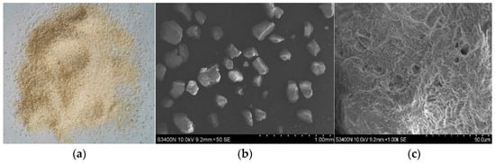
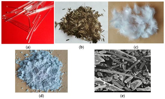
In this study, the raw materials for preparing ordinary-strength SC–ECC (SC–ECC) consist of CW fiber, BF fiber, PE fiber, POM fiber, Conch brand 42.5 ordinary Portland cement, Class I fly ash, coral sand, and artificially prepared seawater. Similarly, for the preparation of HSC-ECC, the raw materials include CW fiber, BF fiber, PE fiber, POM fiber, Yangchun Shanshui brand 52.5 ordinary Portland cement, Eken 920 silica powder, coral sand, and artificially prepared seawater. The coral sand utilized in this research was sieved through a standard fine-aggregate sieve to guarantee that the particle size remained less than 0.6 mm. As illustrated in Figure 1, coral sand assumes a distinct form of light-yellow irregular particles, predominantly composed of calcium carbonate. The seawater employed in this study was prepared synthetically by combining commercial seawater manufactured by Haibao Company (Shanghai, China) with local tap water from Nanning, Guangxi, at a mass ratio of 1:30. In this study, artificial seawater was utilized instead of natural seawater to ensure the reproducibility of the experimental results. Natural seawater’s composition can vary significantly depending on geographical location, seasonal changes, and tide levels, which may introduce uncontrolled variables into the chemical hydration process of the SC-ECC. By preparing artificial seawater according to ASTM D1141-98 [32], the concentration of key corrosive ions (such as and ) was precisely controlled, allowing for a more rigorous analysis of the fiber–matrix interaction and the long-term durability mechanisms. Table 1 presents the main components of the prepared seawater, while Table 2 shows the physical parameters of the fibers used in this study. CW was manufactured by Dongguan Hongxing New Materials Company, BF was produced by Haining Anjie Composite Materials Company (Jiaxing, Zhejiang Province, China), PE was produced by Beijing Quantum Tiandi New Materials Company (Beijing, China), and POM was produced by Chongqing Yuntian Huaju New Materials Company (Chongqing Municipality, China). The properties of the steel and PE fibers listed in Table 2 were provided by the manufacturers and verified through standard tensile tests reported in previous studies. It should be noted that, within the scope of this study, fibers with a diameter ≤ 1 μm are defined as nanoscale fibers, those with a diameter ≥ 100 μm are designated as millimeter-scale fibers, and fibers with a diameter in the range of 2–100 μm are defined as micrometer-scale fibers. The apparent morphology of the fibers is shown in Figure 2. The matrix combinations of SC-ECC and HSC-ECC are shown in Table 3 and Table 4. The fiber dosage for each test group is shown in Table 5. The mix proportions listed in Table 5 were designed to systematically evaluate the synergistic effects of multiscale fibers. Group PE20 served as the control group, incorporating 2% PE fibers to establish the baseline performance of mono-fiber ECC. Group PE20B06 was designed as a comparative hybrid system by introducing basalt fiber (BF), enabling comparison between a conventional micron-scale hybrid system (PE–BF) and the proposed multiscale fiber system.
Figure 1.
Apparent morphology of coral sand. (a) Magnitude ×1. (b) Magnitude ×50. (c) Magnitude ×1000.
Table 1.
Chemical composition of artificially allocated seawater (g/L).
Table 2.
Physical parameters of fiber.
Figure 2.
Apparent morphology of coral sand. (a) POM; (b) BF; (c) PE; (d) CW; (e) CW electron microscope scan.
Table 3.
SC-ECC matrix mixture ratio (kg/m3).
Table 4.
HSC-ECC matrix mixing ratio (Kg/m3).
Table 5.
Fiber dosage for each test group (%).
The M-series (M1, M2, and M3) represented the novel multiscale fiber system comprising nanoscale calcium carbonate whiskers (CW), micro-scale PE fibers, and millimeter-scale polyoxymethylene (POM) fibers. In these groups, the CW content was fixed at 1% to enhance the matrix microstructure, while the POM-to-PE ratio was systematically varied to investigate the optimal substitution rate of POM fibers—which exhibit excellent alkali resistance and matrix compatibility—for maximizing impact resistance and mechanical synergy.
2.2. Specimen Preparation Process
In the specimen preparation process, a QZ-25 planetary mortar mixer (Shaoxing Shangyu Prospecting Instrument Factory, Shaoxing, Zhejiang Province, China) with a 20 L capacity and a 1.5 kW motor was employed. The mixer offered three-speed settings: low, medium, and high; these correspond to blade speeds of 45, 90, and 150 revolutions per minute (r/min), respectively. The mixing procedure was as follows: First, the cementitious material and coral sand were added and mixed at low speed for 1 min. For test groups containing cementitious material and CW, the CW was added along with the cementitious material. Next, seawater containing a water-reducing agent and an antifoam agent was introduced, with mixing conducted at medium speed for 2 to 7 min, 2 min for SC-ECC, and 7 min for HSC-ECC. After mixing, fibers were spread at low speed, followed by additional mixing at medium and high speeds for 2 min and 30 s, respectively. The mixture was then poured into molds, and its surface was leveled with a spatula to ensure it filled the mold. The mixture was vibrated on a vibrating table for 30 s to 1 min. Following vibration, the surface was smoothed and covered with transparent plastic film to prevent water evaporation. The specimens were then left in the room for 24 h before the molds were removed, after which the specimens were immersed in seawater for curing.
2.3. Experimental Methods
2.3.1. Quasi-Static Mechanical Experiments
Following the “Standard Test Methods for Basic Properties of Building Mortar” [33], a cubic specimen with dimensions of 70.7 mm was subjected to a quasi-static cubic compression test. The YAW-2000A pressure testing machine, with a capacity of 2000 kN, was utilized for loading, as depicted in Figure 2 and Figure 3. A 5 kN preloading was applied using force control before formal loading commenced. After 30 s of preloading, displacement control was employed with a loading rate of 1.2 mm/min. Loading ceased when the stress value indicated by the testing machine dropped to 30% of the peak value, with data acquisition performed at a frequency of 2 Hz. During the loading process, the surface deformation of the specimen was measured using digital image correlation (DIC) equipment (MatchID NV, Gent, Belgium), and the vertical deformation of the specimen was subsequently calculated.
Figure 3.
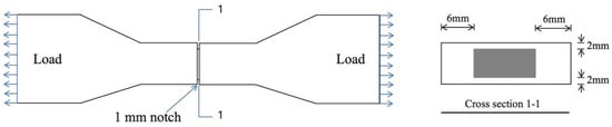
Single-crack tensile specimen.
The AGS-X 100 kN universal testing machine was utilized for the uniaxial tensile test. The dimensions of the testing machine and the specimens are shown in Figure 2, Figure 3, Figure 4 and Figure 5. This testing machine has a load range of ±100 kN. According to the “Test Method for Mechanical Properties of Highly Ductile Fiber-Reinforced Cementitious Composites” [34], a steel fixture in the shape of a dog bone was used to secure the specimen. Displacement control was employed with a loading rate of 0.5 mm/min. Two displacement gauges were fixed on the left and right sides of the specimen to measure displacement changes in the marked section. Additionally, DIC equipment was used to monitor surface deformation and crack development, with a data acquisition frequency of 2 Hz. Three specimens were tested in each group.
Figure 4.
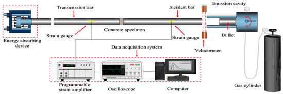
Schematic diagram of the SHPB unit.
Figure 5.
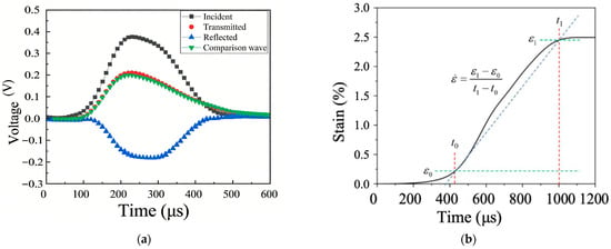
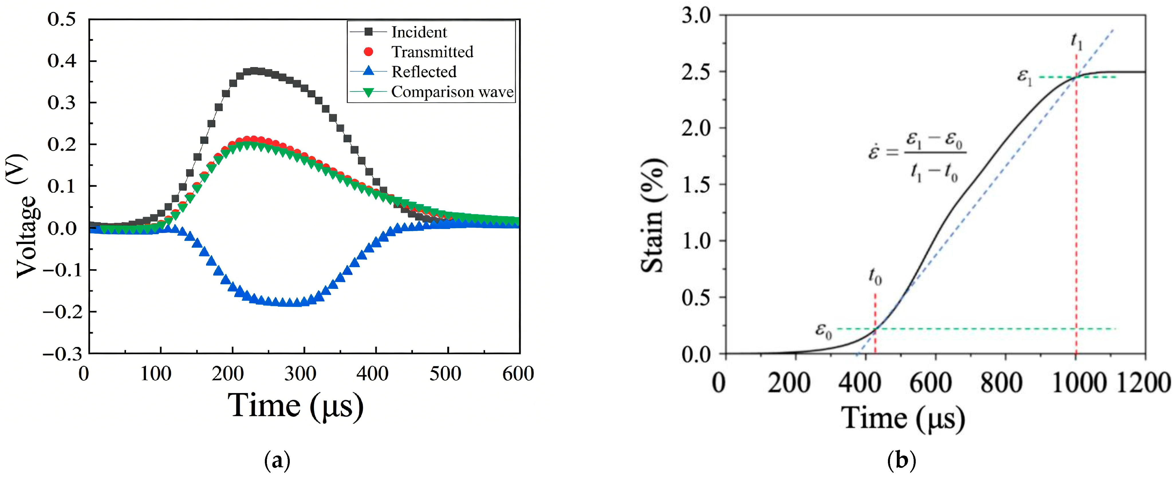
Schematic diagram of the SHPB unit. (a) Comparative dynamic stress balance diagram. (b) Strain rate calculations.
The single-crack tensile test measures the relationship between fiber bridging stress and crack opening displacement, allowing for the analysis of the bridging characteristics of various types of fibers. In reference [35], the central part of the dog-bone specimen’s marked distance section was pre-opened, with the opening size illustrated in Figure 3. Scattering treatment was applied around the opening. The specimens were loaded using the same clamping method as the uniaxial tensile test, at a rate of 0.5 mm/min. Crack opening displacements were measured using DIC equipment during the loading process. Each group comprised three specimens, with results reported as the average of these three specimens.
2.3.2. Impact Compression Test
Impact compression tests were carried out using a 100 mm diameter split Hopkinson pressure bar (SHPB) device [36], which is shown schematically in Figure 4.
Equation (1) is called the three-wave equation, that is, the three waveforms of and measured by strain gauges can be used to deduce the average stress, strain and strain rate of the specimen during the test, which is the three-wave method [37].
where , , and are the average stress (MPa) and strain rate () of the specimen, respectively; , , and denote the incident, reflected, and transmitted strain signals measured by the strain gauges on the bars; E0 and A0 denote the elastic modulus (GPa) and cross-sectional area (mm2) of the compression bar, respectively; and A denotes the cross-sectional area (mm2) of the specimen.
To ensure the reliability of SHPB test data and satisfy the specimen’s stress balance assumption, the loading characteristic time of the stress wave must exceed the time required for the specimen to reach stress equilibrium (achieved by the stress wave traveling back and forth within the specimen multiple times). Thus, this study extended the pulse rising edge time by inserting a waveform shaper (a 20 mm diameter, 2 mm thick rubber disc made of low-yield-strength material) between the bullet and the incident rod. Based on research, when the friction coefficient between the specimen and the rod wall ranges from 0.02 to 0.06, the optimal length-to-diameter ratio is 0.5; accordingly, a 100 mm diameter, 50 mm thick circular cake-shaped specimen was adopted. Prior to the experiment, the specimen’s surface must be polished to ensure that the flatness of both compressive ends is within 0.02 mm, with the flatness test method referenced in [35,38] as follows: (1) measure the specimen’s thickness three times using a micrometer; (2) calculate the pairwise differences ∆da,b = |da − db| (where da and db are any two of the three thickness values); (3) compute the average of these ∆d values—if the average is less than 0.02 mm, the flatness requirement is met.
Before calculating the dynamic compressive stress–strain curve, it is essential to verify the dynamic stress balance to ensure result accuracy. This involves confirming that the comparative wave is defined as the sum of the incident and reflected waves and aligns closely with the transmitted wave [39]. The comparison of dynamic stress balance is illustrated in Figure 5a, where the comparative wave nearly coincides with the transmitted wave, indicating the reliability of the experimental results. To analyze the strain-rate effect on the specimen, the strain rate must be calculated. In this study, the average strain rate is determined from the slope of the ascending section of the strain–time curve under impact loading. The method for selecting the time interval is shown in Figure 5b. Specifically, the transverse coordinate corresponding to the point where the strain increases significantly with time is denoted as t0, and the coordinate where the strain levels off is denoted as t1. The average strain rate is then obtained from ∆ε/∆t.
3. Results and Discussion
3.1. Basic Mechanical Performance
3.1.1. Quasi-Static Compressive Strength
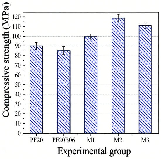
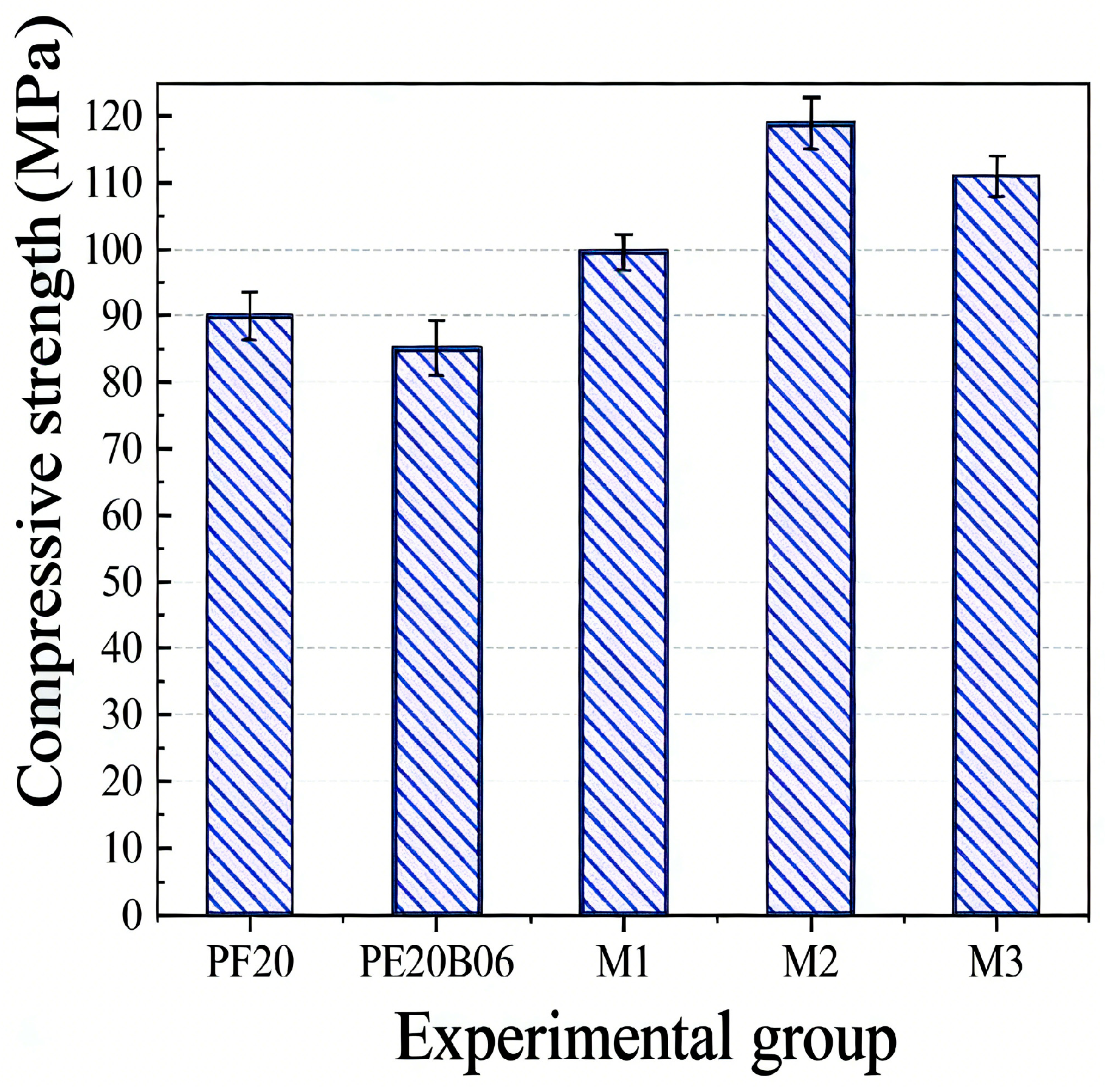
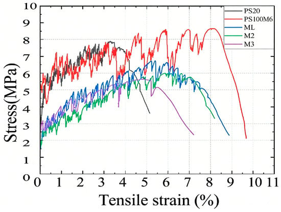
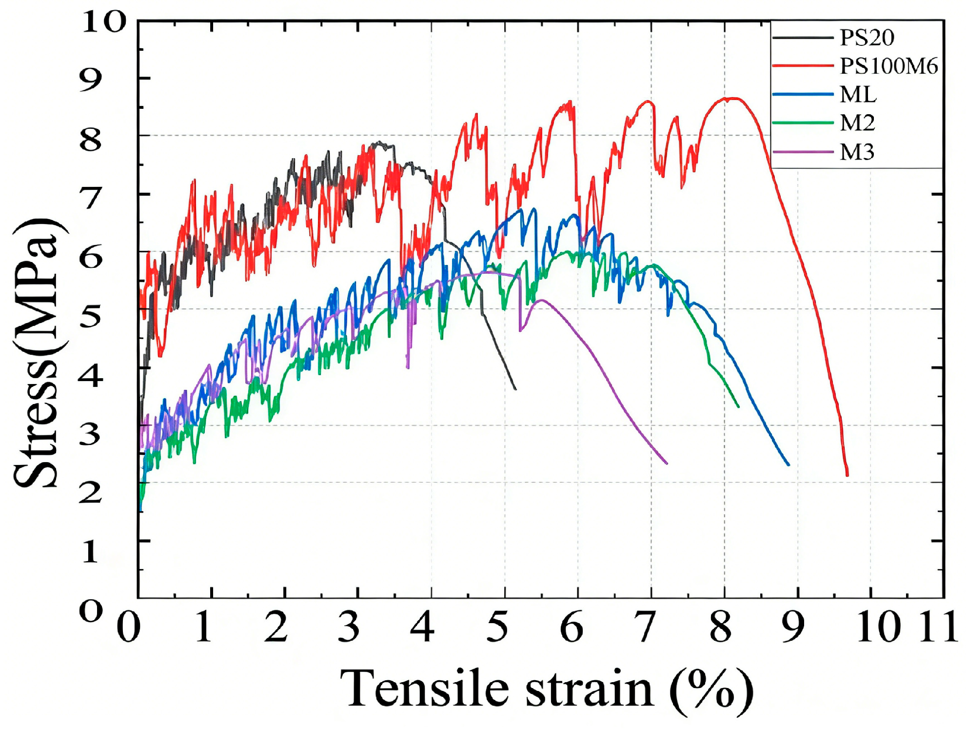
Figure 6 shows the compressive strength of each group of specimens: the multiscale fiber system exhibits better cubic compressive strength, with M2 achieving the highest average value of 119 MPa (33% higher than PE20), while the PE20B06 system has a slightly lower compressive strength than the PE mono-doped system, with an average of 85.2 MPa. Regarding tensile performance, Figure 7 presents the average uniaxial tensile stress–strain curves of each fiber-reinforcement system. Compared to the PE single-doped system, both the PE-BF and multiscale fiber systems have higher maximum tensile strains; the PE-BF system gains increased tensile and initial crack strengths due to finer fiber diameter and superior chemical bonding with the matrix, whereas the multiscale system, featuring larger-diameter POM fibers that only form frictional bonds with the matrix, exhibits smaller bridging stresses and thus lower tensile strength. Specifically, the average tensile strengths of the PE single-doped, PE-BF compounded, and multiscale compounded fiber systems are 7.9 MPa, 8.6 MPa, and 6.0 MPa, respectively, with corresponding average maximum tensile strain capacities of 4.2%, 7.5%, and 7.3%. The consistent tensile curves of the multiscale fiber specimens indicate uniform performance.
Figure 6.
Compressive strength of each group of specimens.
Figure 7.
Comparison of tensile mean curves for each group of specimens.
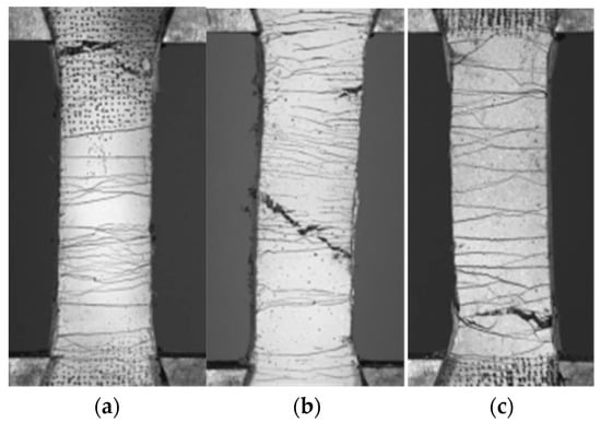
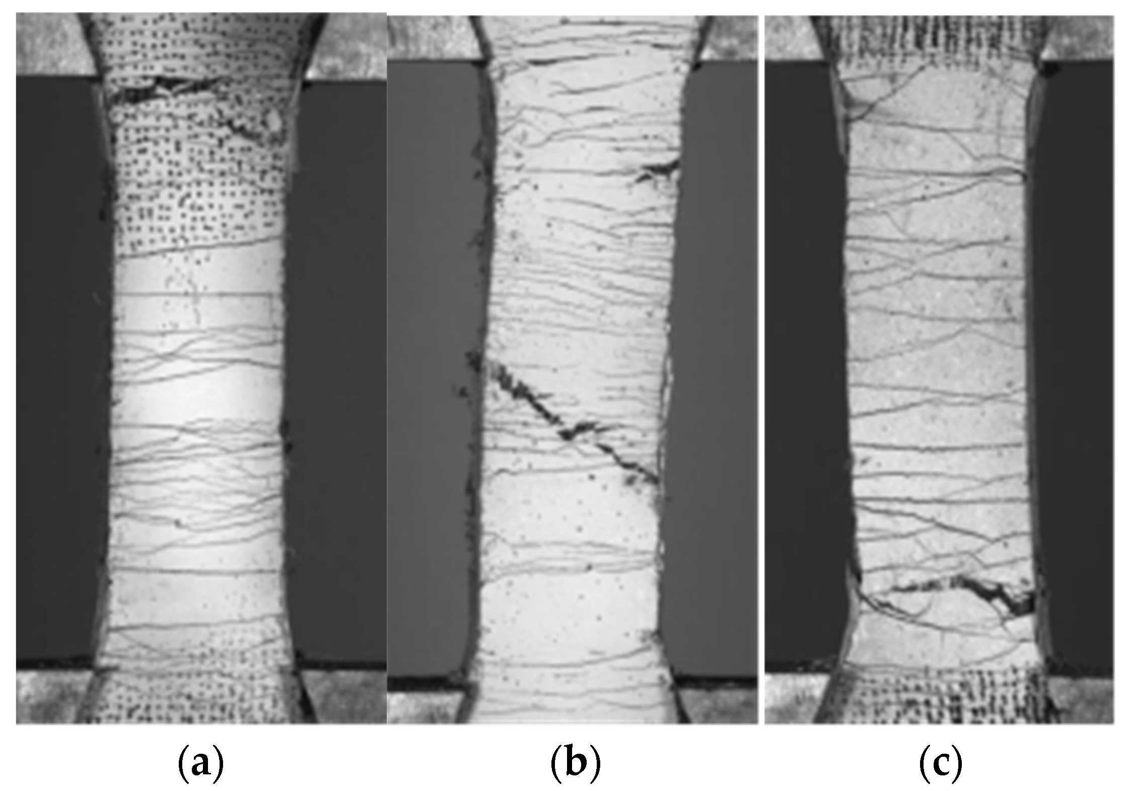
Figure 8 illustrates the crack modes for each group of specimens. Given the similarity in crack modes across the multiscale fiber groups, specimen M2 was selected as a representative for comparison with the PE mono-doped and PE-BF compounded groups.
Figure 8.
Comparison of crack modes for each group of specimens. (a) PE; (b) PE-BF; (c) M2.
The multiscale composite doped fiber system effectively fills the matrix pores, with minimal physical interference between fibers of different scales, thereby reducing defects caused by agglomeration and entanglement—thus demonstrating superior compressive strength compared to both PE single-doped and PE-BF composite-doped systems and enhancing the impact compression strength and impact resistance of SC-ECC. However, BF fibers are difficult to disperse; their high concentration leads to uneven distribution and matrix defects, resulting in the slightly lower compressive strength of PE20B06 compared to PE20 [40]. Regarding crack behavior, the crack width ranking is: multiscale compounded fiber system > PE single-doped system > PE-BF fiber compounded system. The PE-BF system enhances SC-ECC’s multi-seam cracking capacity, forming fine and dense cracks, while the multiscale system (containing POM, PE, and CW) exhibits wider cracks randomly distributed along the specimen’s scaled segments. This is attributed to the multiscale system’s macro-fibers (POM and PE) having hydrophobic surfaces that only form frictional bonding with the matrix, which is less effective for crack width control than the PE-BF system’s combination of chemical and frictional bonding, which better optimizes SC-ECC’s tensile properties.
3.1.2. Single-Crack Tensile Curve
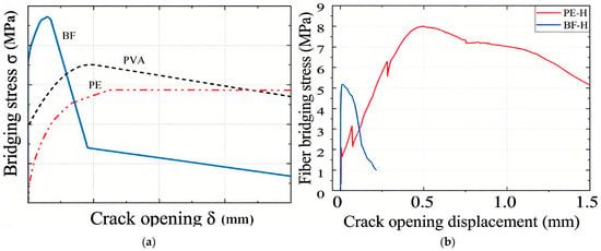
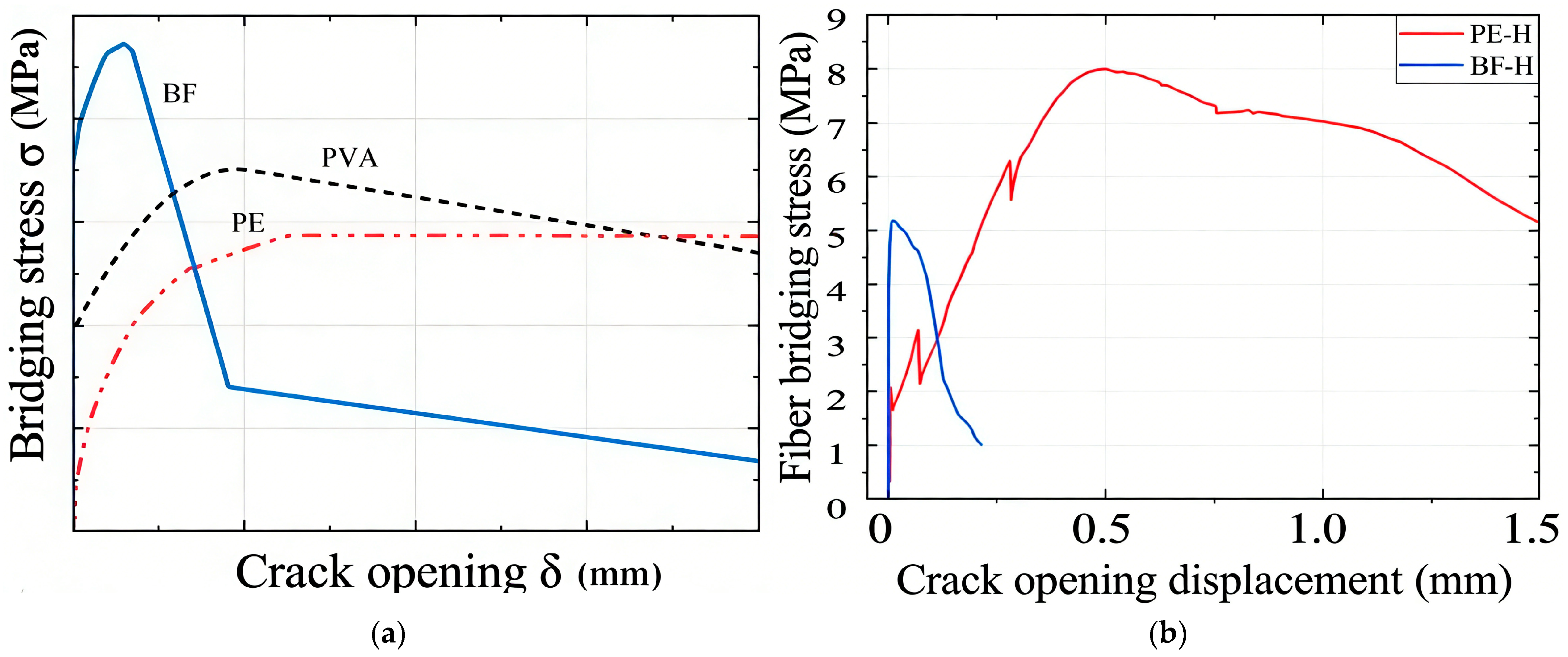
According to the ratio of chemical bonding to frictional bonding in the fiber–matrix interface, the fiber bridging stress–crack opening displacement curves are mainly classified into three categories when the fibers resist the development of cracks in the matrix (based on the classification in [6]) as shown in Figure 9a. These three categories of curves correspond to the three types of fiber bridging, namely, PVA, BF, and PE, respectively, in this study.
Figure 9.
Bridge stress–crack opening displacement curves for each fiber. (a) Three types of fiber bridging curves. (b) Bridging curves of BF and PE in HSC-ECC.
Excessive bond strength reduces the complementary energy in the fiber bridging stress–crack opening displacement curve, making it more challenging for the specimen to satisfy the energy criterion for multi-seam cracking. This, in turn, decreases the tensile deformation capacity of ECC [7]. The hydrophilic nature of the BF surface leads to a strong chemical bond with the matrix, whereas the hydrophobic PE fiber surface results in only frictional bonding with the matrix, lacking chemical bonding [41].
As shown in Figure 9, over 80% of BF’s maximum bridging stress stems from its chemical bond with the matrix, occurring at small crack openings; however, BF’s poor deformability leads to minimal slip enhancement after debonding, resulting in a rapid post-peak decline in bridging stress. In contrast, PE fibers lack chemical bonding with the substrate: as cracks propagate, PE fibers deform and are gradually pulled out, with the crack-section area squeezing and swelling to form an anchoring effect, while surface damage to PE fibers increases frictional engagement—these factors enhance the bridging force during pull-out, enabling ECC strain hardening and effective tensile load transfer across cracks to induce new cracks in uncracked regions [41]. Since PE fiber bridging relies primarily on friction, its bridging stress rises gradually with crack propagation, and the stress at debonding is less than 20% of the maximum. The incorporation of BF in HSC-ECC allows the PE-BF hybrid system to provide higher fiber bridging stresses at smaller crack widths, meeting the strength criterion earlier and facilitating stress transfer to form more extensive crack distribution, with PE20B06 achieving the optimal balance of tensile strength and strain capacity. POM fibers exhibit interfacial properties similar to PE, with only frictional bonding to the cement matrix, resulting in less effective crack control in the multiscale fiber system.
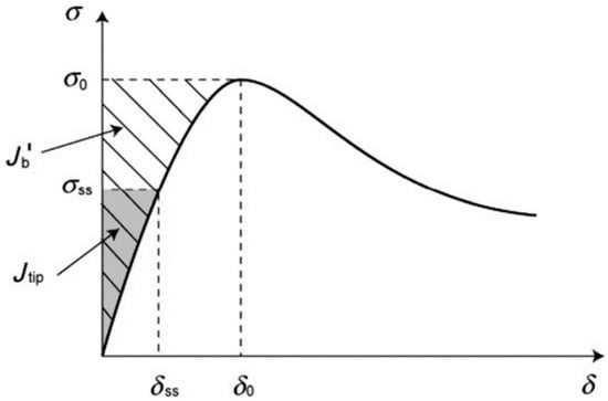
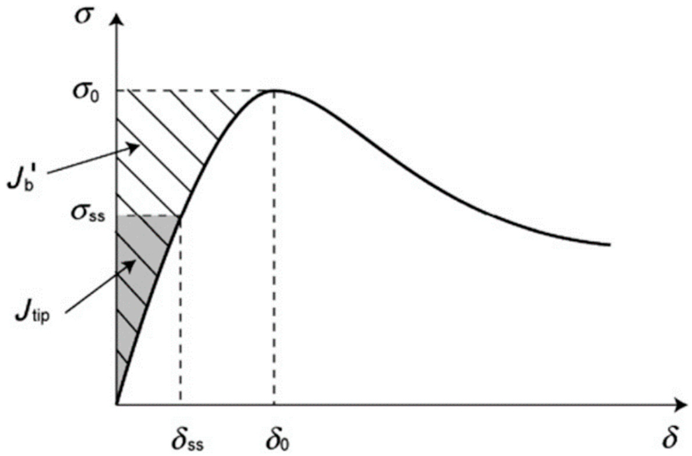
To achieve tensile strain hardening in ECC, both the strength and energy criteria must be met. These criteria are influenced by the properties of the matrix, fibers, and fiber–matrix interface [42]. When using multiscale fiber compounding, matching the interfacial properties of different fibers within the same matrix can be challenging, potentially leading to suboptimal tensile strain-hardening properties [43]. The conditions for energy and strength in ECC multiscale cracking are formulated as follows:
where is the residual energy () calculated from the area under the bridge stress–crack opening curve between the bridge stress and the crack expansion ; is the bridge stress (MPa) and is the crack opening displacement (mm). is the maximum bridge stress (MPa) corresponding to the crack opening. represents the crack-tip toughness (J/m2), where is the matrix fracture toughness (MPa·m1/2) and Em is the elastic modulus of the matrix (GPa). denotes the matrix tensile rupture strength (MPa), which is determined based on the matrix fracture toughness . The crack size represents the characteristic crack length (mm), which is currently attributed to the matrix cracking strength. The energy conditions are depicted in Figure 10, with the diagonal region being the complementary energy provided by fiber bridging and the shaded region being the crack tip toughness [44].
Figure 10.
Fiber bridging stress–crack width curve.
The surface pores of coral sand form embedded bonds with cement paste, enhancing the strength of the coral sand–substrate interface transition zone and thereby increasing the substrate’s tensile strength. Per ECC’s strength criterion, higher substrate strength requires increased fiber-bridging stresses to satisfy the multi-seam cracking condition, posing a challenge for achieving this property in SC-ECC.
3.2. Impact-Compression Damage Patterns
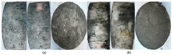
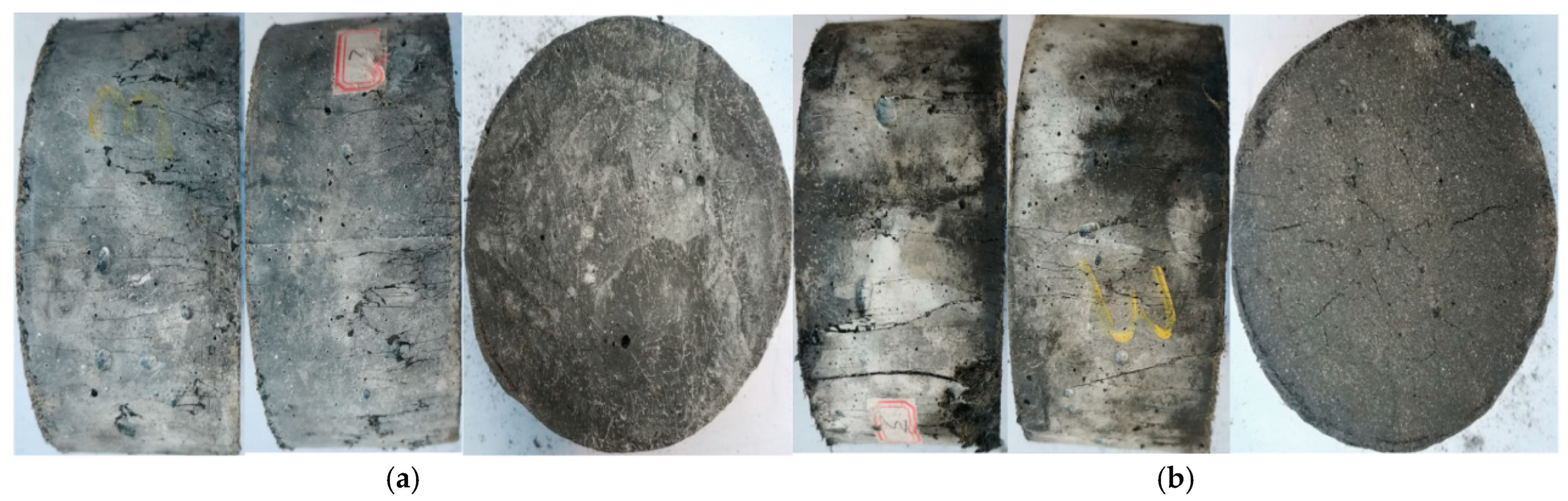
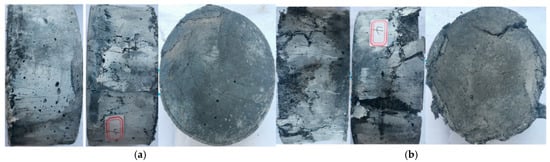
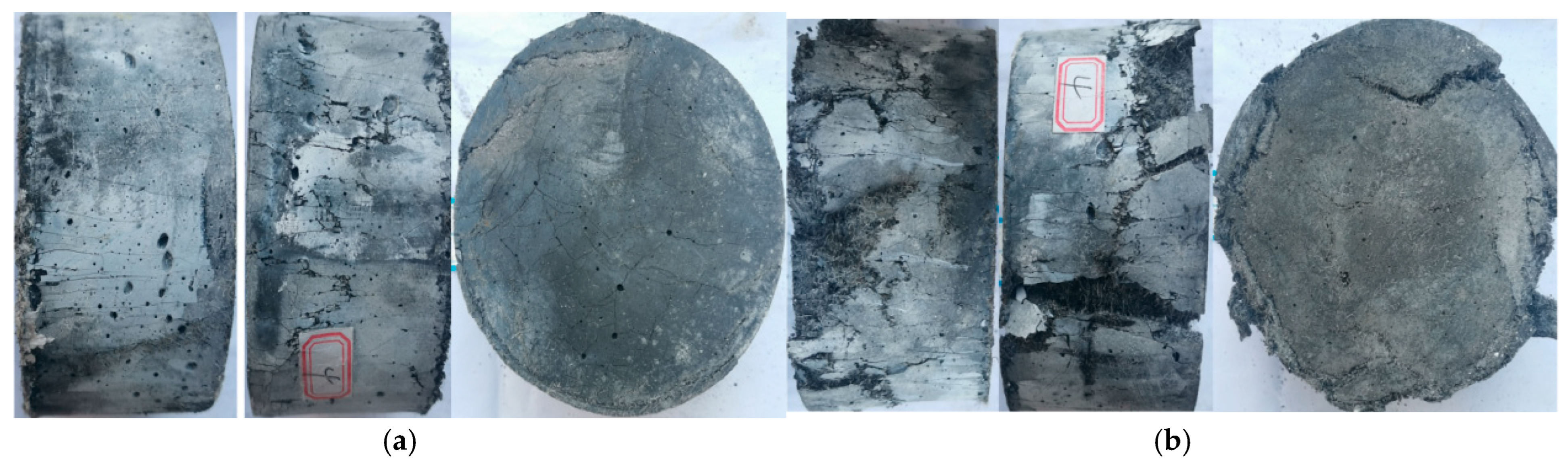
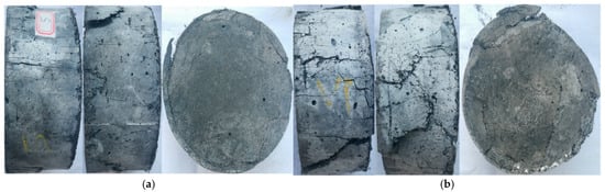
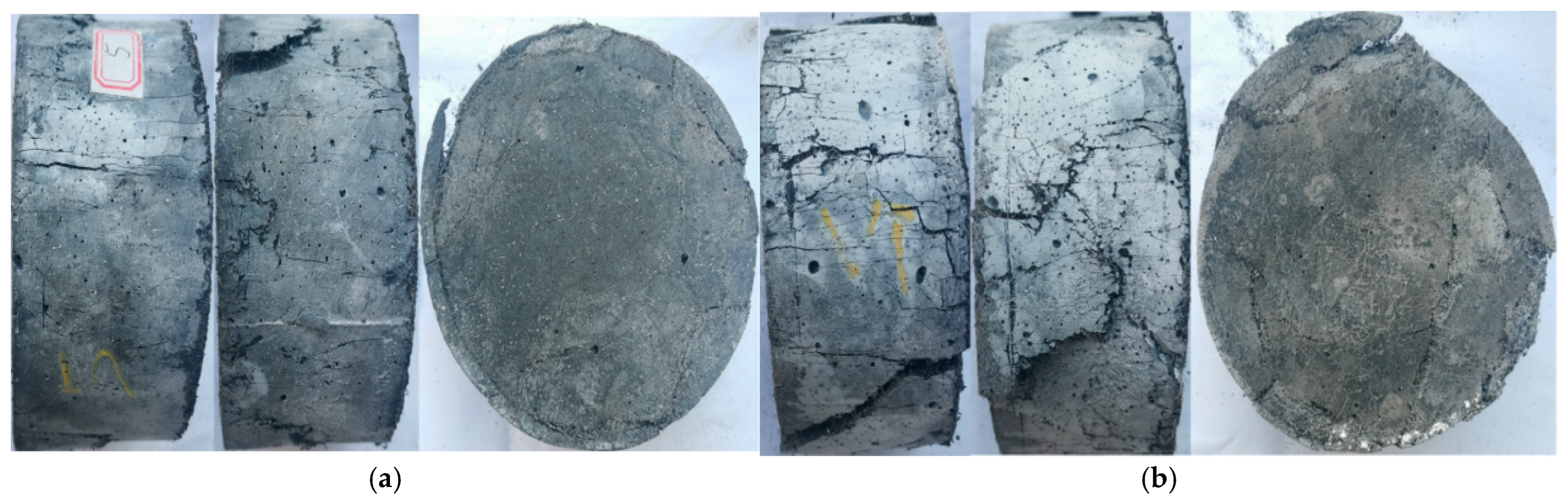
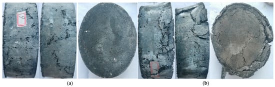
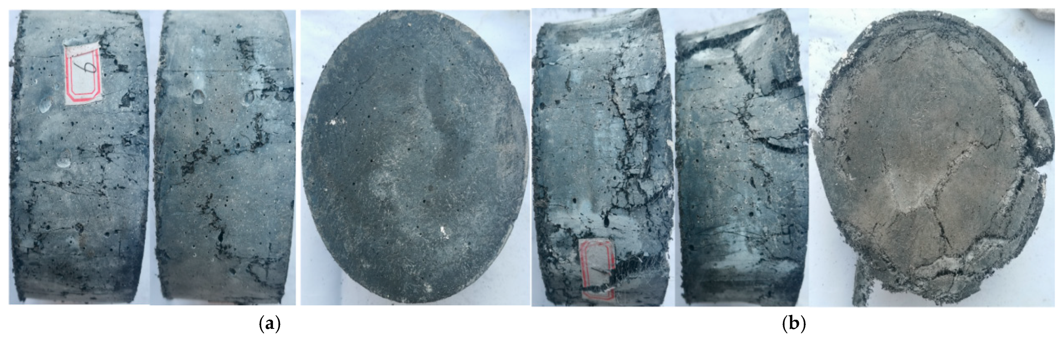
The damage patterns of each group of HSC-ECC are shown in Figure 11, Figure 12, Figure 13 and Figure 14, respectively.
Figure 11.
Damage patterns of PE at medium and high strain rates. (a) PE20—medium strain rate; (b) PE20—high strain rate.
Figure 12.
Damage patterns of PE20B06 at medium and high strain rates. (a) PE20B06—medium strain rate; (b) PE20B06—high strain rate.
Figure 13.
Damage patterns of M2 at medium and high strain rates. (a) M2—medium strain rate; (b) M2—high strain rate.
Figure 14.
Damage patterns of M3 at medium and high strain rates. (a) M3—medium strain rate; (b) M3—high strain rate.
As shown in the figures, at medium strain rates, the specimens reinforced with PE and BF (PE20B06) demonstrate superior crack control and uniform crack distribution, characterized by numerous fine cracks on both the side and end faces. The incorporation of basalt fiber (BF) creates a chemical bond at the fiber–matrix interface, which reduces the required crack opening displacement while maintaining stable bridging stresses, thereby enhancing crack control. However, the addition of BF also introduces local defects due to potential uneven dispersion. Because of the limited extensibility of BF, the fibers fracture once cracks widen beyond a critical point, losing their bridging capacity. Consequently, the PE20B06 group experiences more severe damage than the PE20 group under high-strain-rate conditions.
When comparing the damage morphology at medium and high strain rates, the crack control performance of the POM-PE hybrid systems (M2 and M3) is inferior to that of the high-strength matrix group (H2). This is attributed to the fact that the interfaces between both POM and PE fibers and the matrix are primarily governed by frictional bonding. At medium strain rates, M2 and M3 exhibit fewer fine cracks and a more pronounced tendency for surface spalling. Furthermore, the addition of calcium carbonate (CW) whiskers increases the energy threshold required for matrix cracking [16]. Consequently, the probability of crack initiation in the M2 and M3 matrices is lower when subjected to the same incident wave energy.
The multiscale hybrid fiber system significantly improves the dynamic compressive strength of the M2 and M3 groups. However, due to the larger diameter of POM fibers, their total interfacial contact area is smaller than that of PE fibers at an equivalent volume fraction. As the replacement rate of PE fibers by POM fibers increases, the overall crack-bridging efficiency decreases. This leads to reduced crack control at high strain rates, where M2 and M3 exhibit more substantial damage, characterized by severe surface spalling and matrix fragmentation.
3.3. Impact Compression Stress–Strain Curves
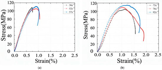
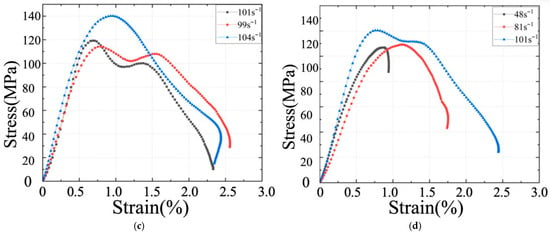
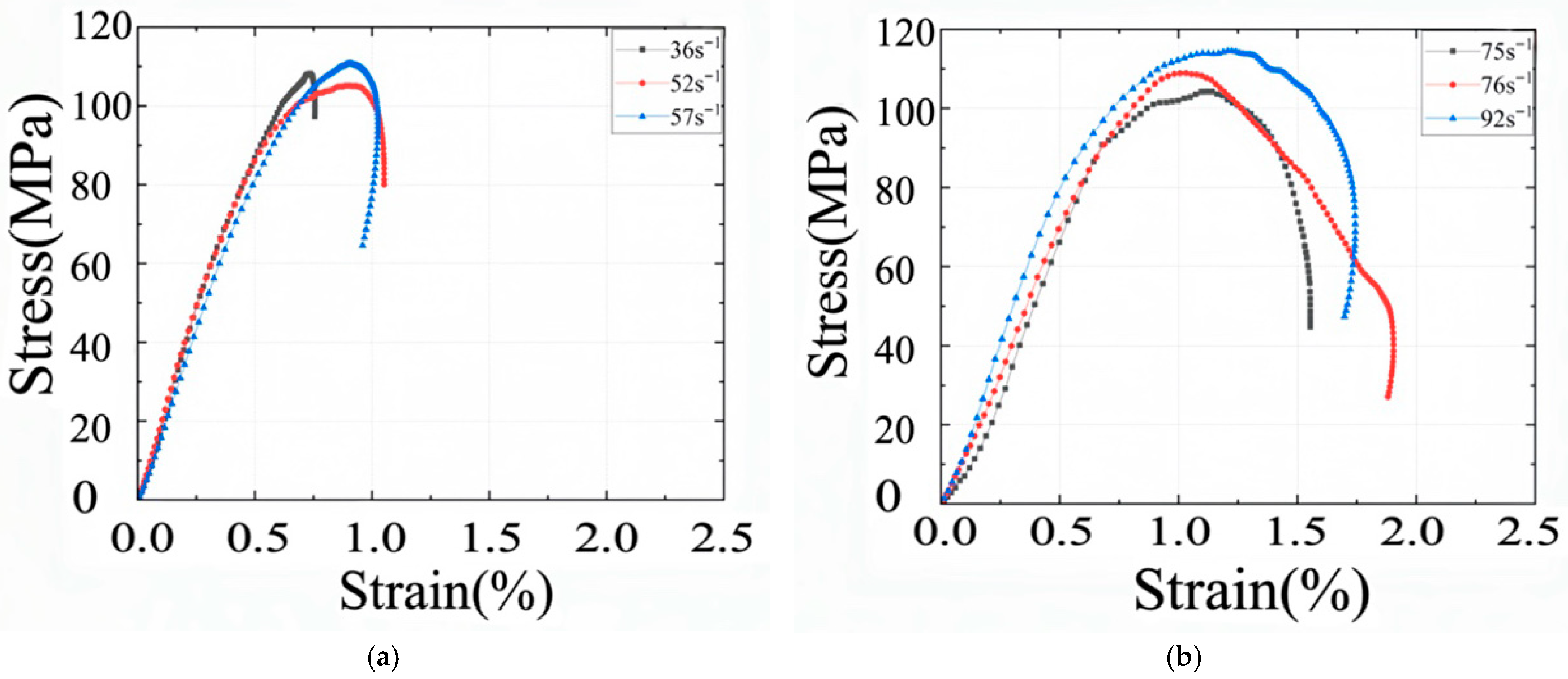
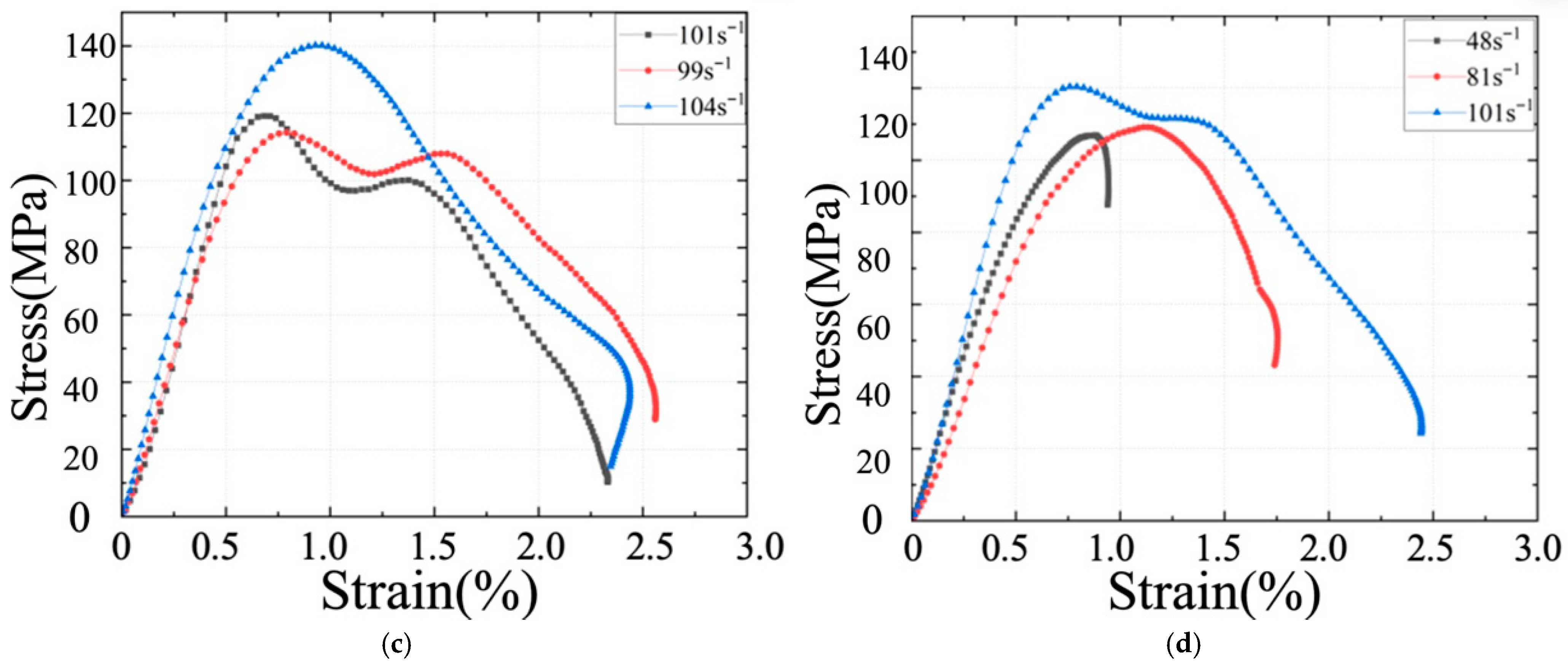
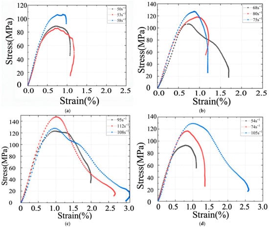
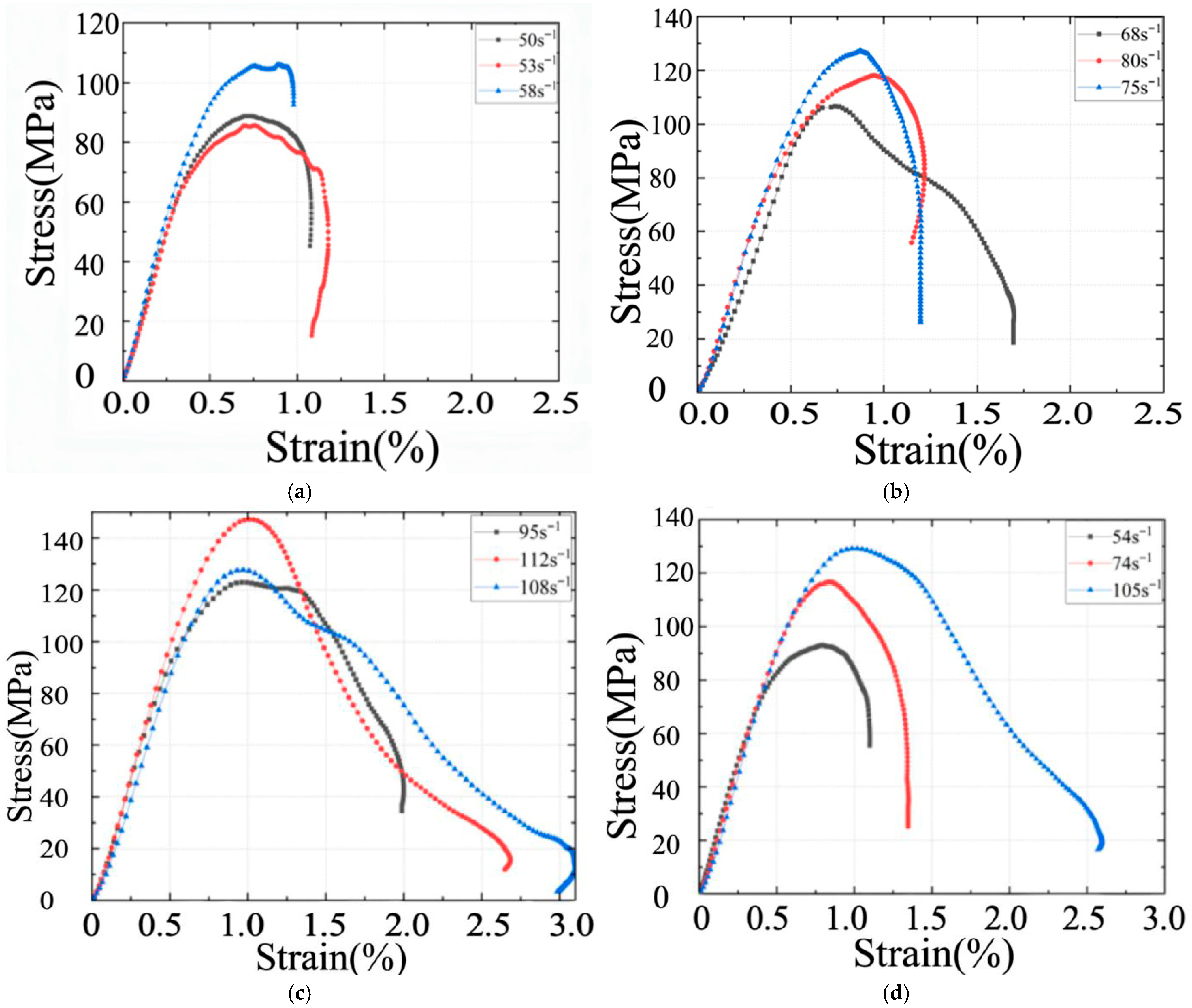
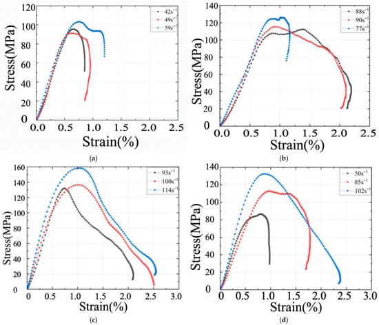
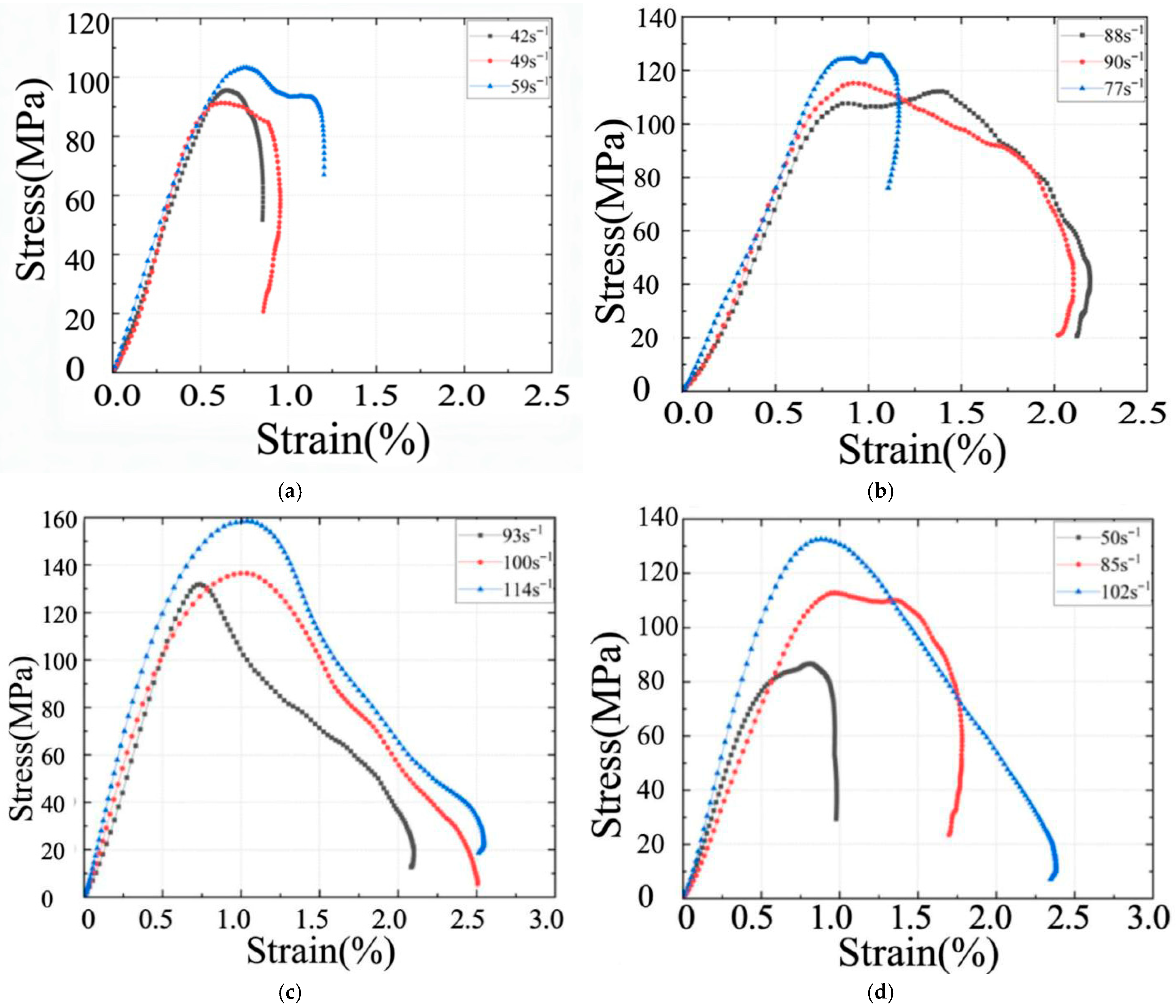
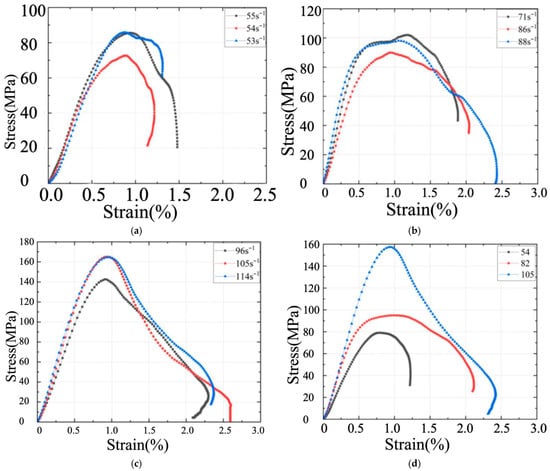
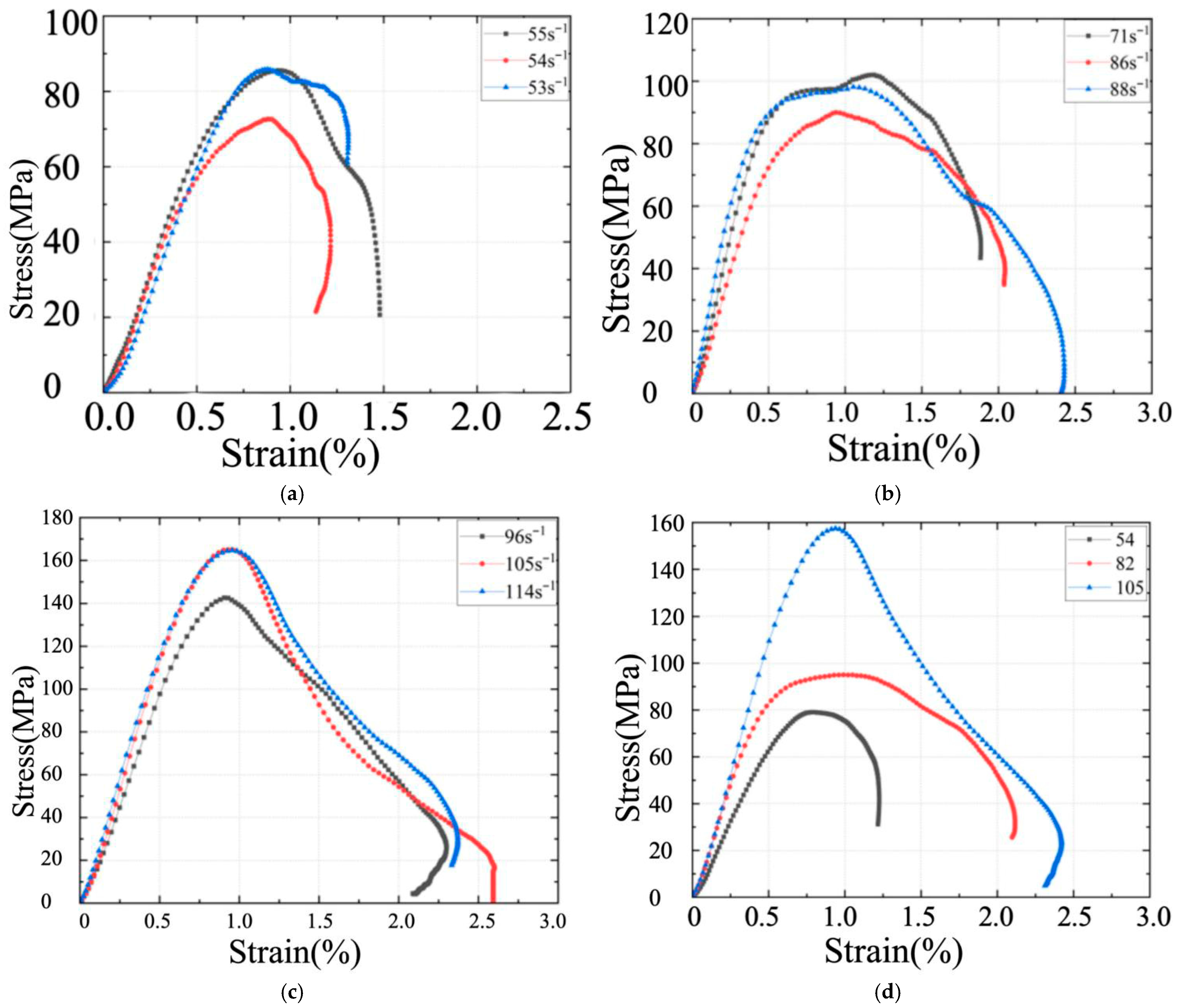
Figure 15, Figure 16, Figure 17 and Figure 18 display the dynamic compressive stress–strain curves for HSC-ECC specimens at various strain rates, along with the corresponding average stress–strain curves for each strain rate. As the strain rate increases, the stress–strain curves become more pronounced, indicating greater energy absorption. At low strain rates, the specimens did not exhibit significant damage, resulting in almost no post-peak section. As the strain rate increased, the specimens experienced damage and substantial deformation, which led to increased impact energy absorption and a more pronounced post-peak section on the curves.
Figure 15.
Impact compression stress–strain curve of PE20. (a) curve for each specimen in the low-strain-rate range of PE20. (b) curves for each specimen in the medium-strain-rate range in PE20. (c) curve for each specimen in the high-strain-rate range of PE20. (d) Average curves for each strain rate range of PE20.
Figure 16.
Impact compression stress–strain curve of PE20B06. (a) curves for each specimen in the low-strain-rate range of H2. (b) curves for each specimen in the medium-strain-rate range in H2. (c) curves of each specimen in the high-strain-rate range of H2. (d) Average curve for each strain rate range of H2.
Figure 17.
Impact compression stress–strain curve for M2. (a) curve for each specimen in the low-strain-rate range of M2. (b) curve for each specimen in the medium-strain-rate range in M2. (c) curves for each specimen in the high-strain-rate range of M2. (d) Average curve for each strain rate range of M2.
Figure 18.
Impact compression stress–strain curve of M3. (a) curve for each specimen in the low-strain-rate range of M3. (b) curve for each specimen in the medium-strain-rate range in M3. (c) curves for each specimen in the high-strain-rate range of M3. (d) Average curve for each strain rate range of M3.
In addition to the qualitative changes in curve shape, clear quantitative differences can be observed in peak stress, stiffness evolution, and post-peak deformation behavior among different fiber systems. With increasing strain rate, all specimens exhibit a steeper ascending branch and higher peak stress, indicating a pronounced strain-rate-strengthening effect of the SC-ECC matrix. This dynamic stiffening reflects the limited time available for microcrack development and crack coalescence, resulting in higher apparent resistance during rapid loading.
Compared with the mono-fiber PE20 specimens, hybrid fiber-reinforced specimens (PE20B06) show moderately enhanced peak stress and slightly improved post-peak stability, suggesting that basalt fibers contribute to crack bridging at early stages but provide limited deformation capacity once fracture initiates. In contrast, multiscale fiber-reinforced specimens (M2 and M3) exhibit not only the highest peak stresses but also significantly extended post-peak deformation segments, reflecting improved crack dispersion, delayed localization, and more effective energy dissipation through multiscale fiber pull-out and interfacial friction.
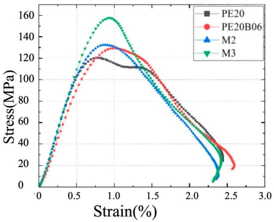
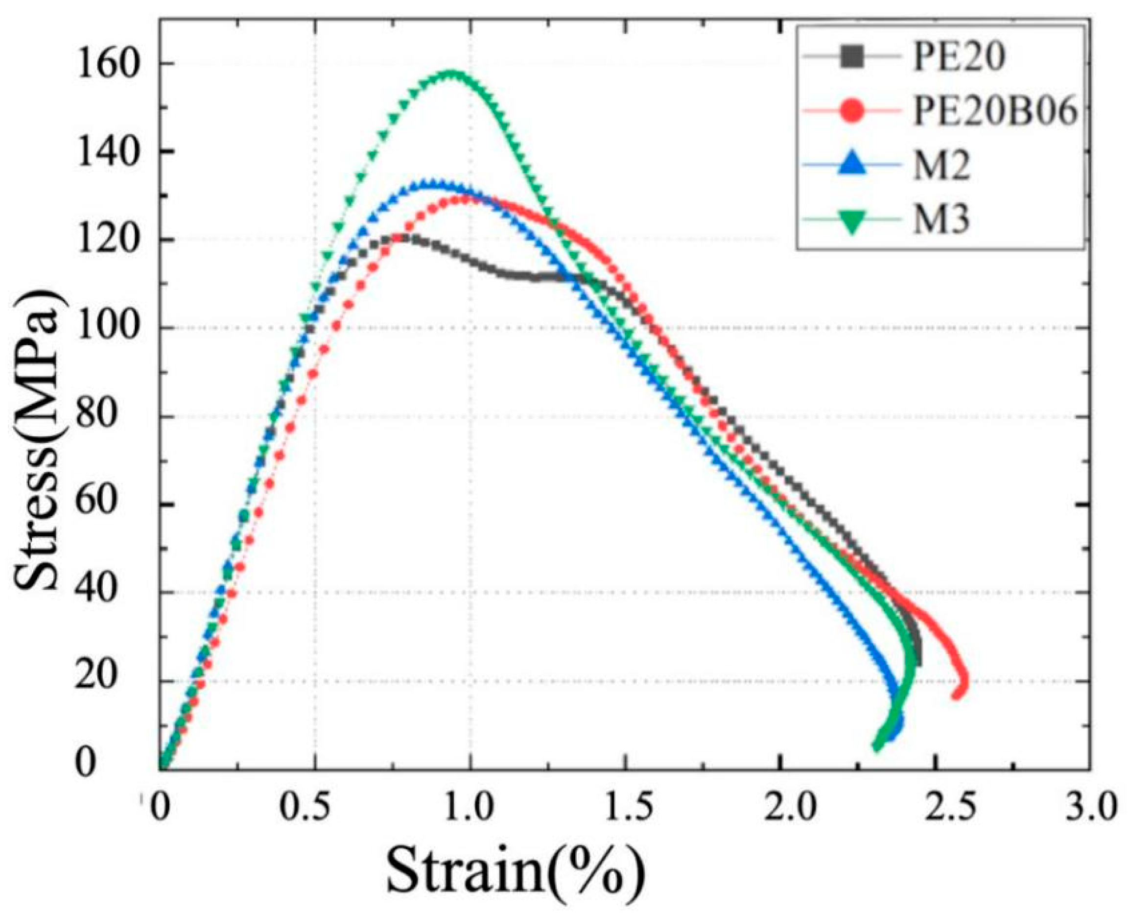
Furthermore, the descending branches of the stress–strain curves become progressively gentler for multiscale fiber systems, especially at high strain rates, indicating enhanced post-peak load-carrying capacity and reduced brittleness. This behavior confirms that coordinated reinforcement across nano-, micro-, and millimeter-length scales promotes stable crack propagation and prevents sudden catastrophic failure, which is consistent with the superior impact compression toughness and damage resistance observed in subsequent sections. The SC-ECC exhibits more extensive damage at higher strain rates, which highlights the differences between various fiber reinforcement systems. Comparison of the curves across test groups reveals that M2 and M3 demonstrate superior peak strength and post-peak ductility compared to other groups. Specifically, the peak strength of M3 approaches 160 MPa, approximately 28% higher than that of PE20. This indicates that different scales of fiber doping significantly enhance the impact compression resistance of SC-ECC. Figure 19 shows the comparison of impact compression stress–strain curves for each specimen group at high strain rates.
Figure 19.
Comparison of average dynamic compression stress–strain curves of various groups of HSC-ECC in the high-strain-rate range.
3.4. Impact Compression Strength and DIF
The dynamic compressive strength () in this study is determined as the peak stress obtained from the dynamic stress–strain curves derived from the SHPB test. As the strain rate increases, the specimen undergoes a transition from quasi-static failure to high-speed fragmentation, and the maximum stress value reached during this transient loading process is recorded as the dynamic strength. To ensure statistical reliability, the reported values are the average of at least three valid impact tests for each group.
Since ECC is a non-homogeneous material and variations in the flatness of the specimen’s end face can occur, a permissible deviation of 20% in peak stress is accepted for specimens tested under the same SHPB impact compression conditions. Specimens with deviations exceeding 20% are discarded, and the average of the remaining peak stresses is used as the representative value of the specimen’s dynamic compressive strength under these conditions [45]. Under impact compression loading, the dynamic compressive strength of the specimen increases with the strain rate, demonstrating a clear strain-rate effect. The sensitivity of this effect is quantified by the dynamic increase factor (DIF), calculated as follows:
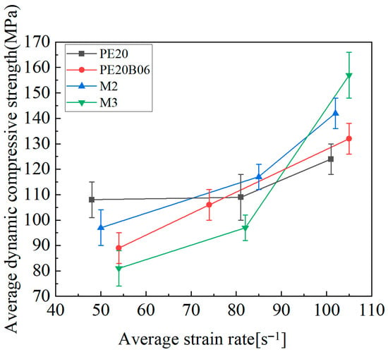
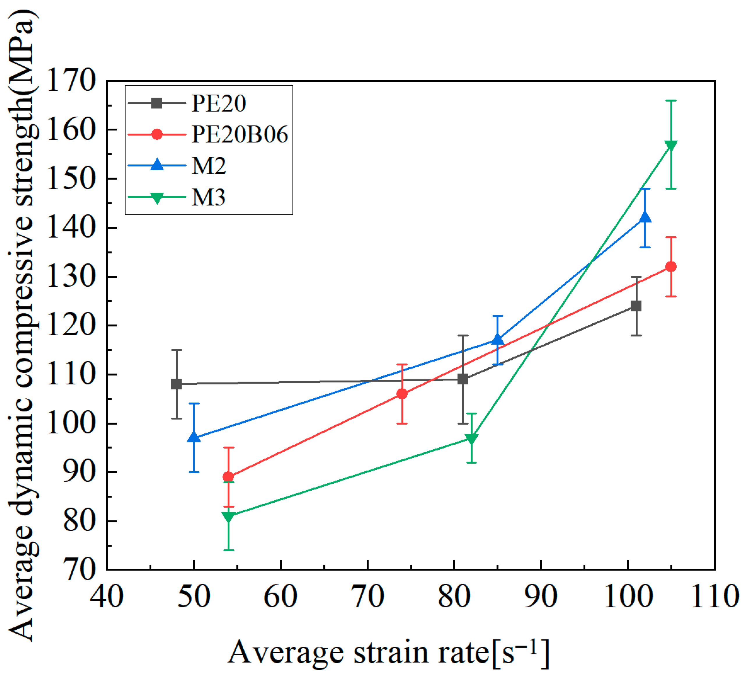
where is the dynamic compressive strength of the specimen at each strain rate and is the quasi-static compressive strength of the specimen. The impact compression strength of each group of specimens at different average strain rates is shown in Figure 20.
Figure 20.
Average dynamic compressive strength of SC-ECC under different strain rates.
For HSC-ECC, the dynamic increase factor for both M2 and M3 is less than 1 at low strain rates. This is likely because the impact energy at these rates is insufficient to cause specimen failure, resulting in measured dynamic compressive strengths that are lower than the quasi-static compressive strengths. During loading, the specimens primarily underwent elastic deformation, which recovered upon unloading. At high strain rates, the average dynamic compressive strengths were 124 MPa for PE20, 132 MPa for PE20B06, 142 MPa for M2, and 157 MPa for M3.
Currently, five main explanations for the strain-rate effect observed in SHPB tests have been proposed: thermal activation, free water effects, aggregate destruction, crack extension rate, and inertia effects. Among these, the inertia effect suggests that under axial impact loading, the specimen deforms transversely due to Poisson’s ratio, with the inertia effect imposing transverse constraints in a three-way force state, thereby increasing the specimen’s compressive strength [46].
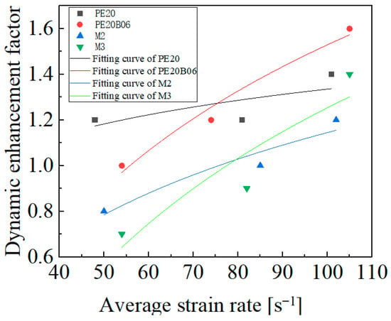
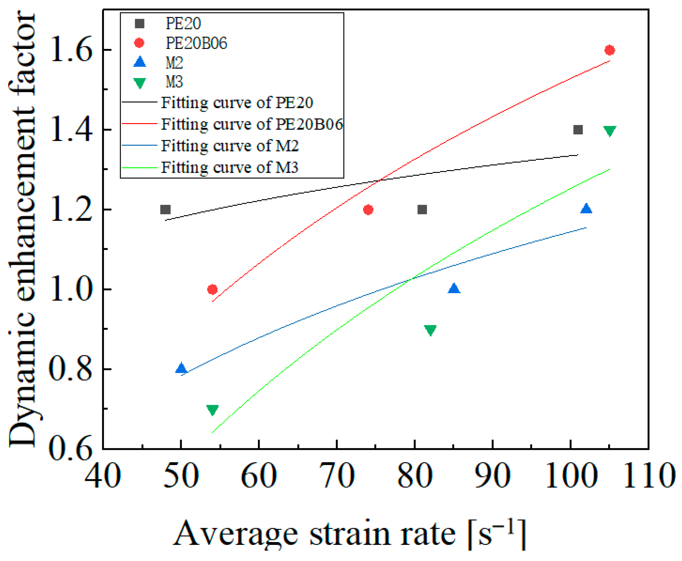
The relationship between strain rate and the DIF for HSC-ECC has been fitted using the dynamic increase factor fitting formula from Chen [47]. The resulting DIF vs. strain-rate fitting equation for SC-ECC is as follows:
where is the dynamic increase factor (ratio of dynamic to quasi-static strength), acting as the dependent variable is the average strain rate () and the independent variable; and and are empirical constants representing the slope and intercept determined via regression analysis. The calculated fitting parameters for each group are detailed in Table 6, with the corresponding regression curves presented in Figure 21.
Table 6.
Fitting parameters (a, b) and correlation coefficients (R2) for the dynamic increase factor (DIF) models.
Figure 21.
SC-ECC’s fitting curve.
3.5. Impact Compression Toughness
Currently, there is no standardized method for calculating the impact compression toughness of materials. Impact toughness is quantitatively evaluated by calculating the energy absorption capacity, defined as the area under the dynamic stress–strain curve. In this study, the key indicators include pre-peak toughness (), peak toughness (), and overall toughness () to characterize the energy dissipation at different deformation stages [48,49]. The impact compression toughness of specimens was determined by integrating the average stress–strain curves over different strain rate ranges.
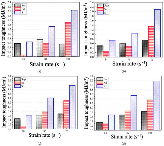
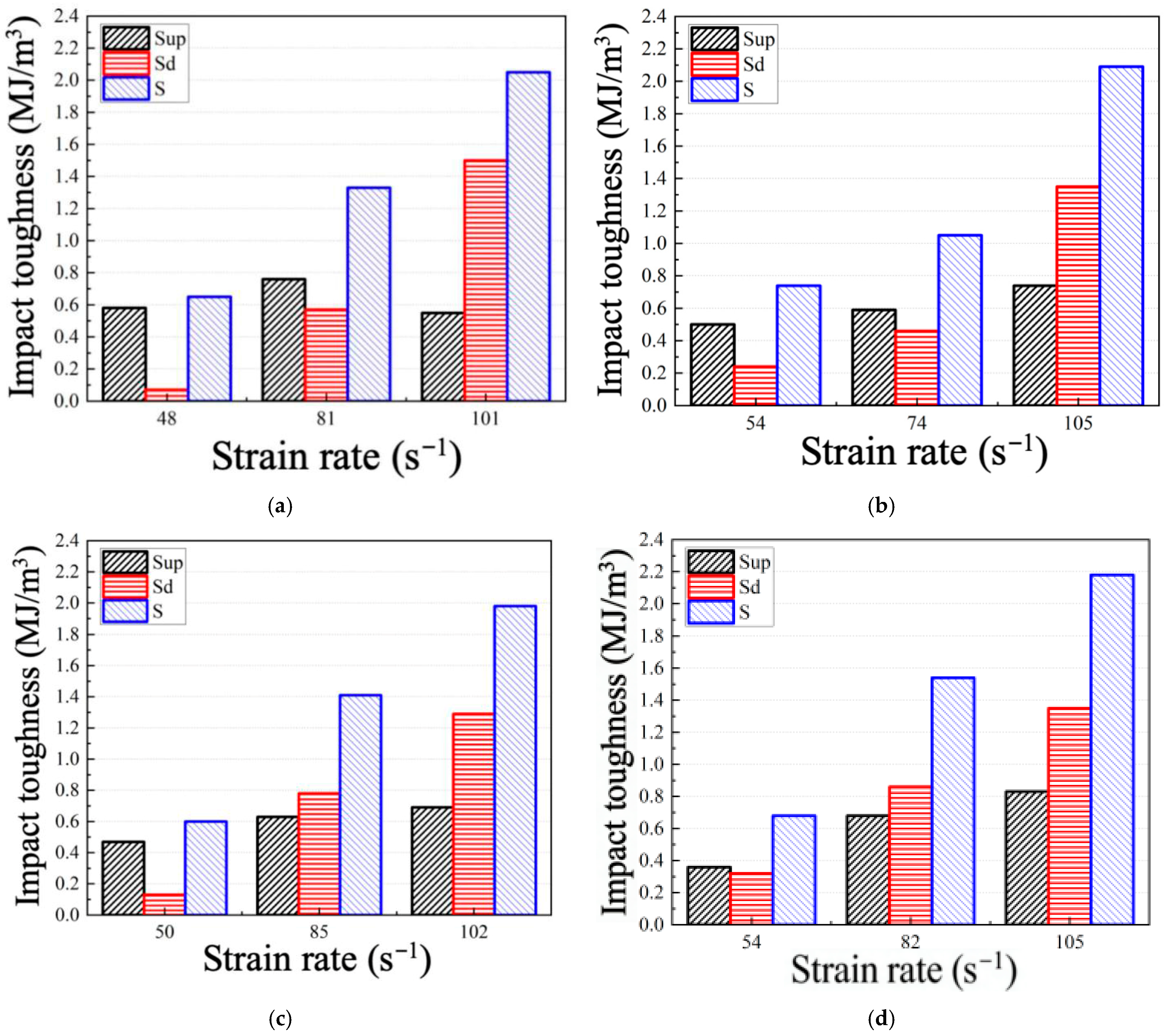
As shown in Figure 22, the full-curve toughness of each specimen increases with the strain rate. This toughness is primarily related to the energy absorbed before the applied impact load reaches the specimen’s critical damage threshold. For HSC-ECC, the full-curve toughness of specimens at low strain rates is similar, ranging between 0.6 and 0.7 MJ/m3. At low strain rates, the pre-peak toughness of each specimen contributes more to the full-curve toughness than the post-peak toughness as the strain rate increases, the proportion of rises while decreases. This is because, at low strain rates, specimens primarily absorb energy through substrate deformation and the formation of micro-cracks. As impact energy increases, cracking damage occurs, and the fibers provide bridging through friction with the matrix, enhancing post-peak toughness . In dynamic compression damage, the fibers within the SC-ECC absorb and dissipate energy primarily through deformation and slip friction. Consequently, with increasing strain rates, the specimen’s full-curve toughness and post-peak toughness increase significantly, with rising more sharply than the pre-peak toughness .
Figure 22.
Impact toughness of HSC-ECC in various stages. (a) PE20; (b) PE20B06; (c) M2; (d) M3.
When multiscale compound-doped fibers are used, their strength increases successively across low-, medium-, and high-strain-rate ranges. This results in a higher overall strength and a more balanced strength distribution across each strain rate range, making them better suited to handle more complex working conditions.
3.6. Analysis of Dynamic Composite Performance Indicators
To comprehensively evaluate the dynamic mechanical properties of the test group, the dynamic compressive strength, impact compressive toughness, and damage degree from the impact test results were scored to identify the fiber-reinforcement method with the best overall performance. The impact damage degree of the specimens was classified into five grades, as shown in Table 7, with a higher grade indicating more severe damage and a lower comprehensive performance score.
Table 7.
SC-ECC impact damage level classification basis.
The dynamic mechanical property scores, , for each test group are shown in Table 8. In the high-strain-rate range, where the specimens are more fully destroyed, the corresponding dynamic compressive strength and impact compression toughness more accurately reflect the impact performance of the specimens. Therefore, the average compressive strength and full-curve toughness of each group’s specimens under high strain rates were selected as the calculated values for the indices and . The calculation formula is as follows:
where , , and represent the performance indicators for the dynamic compressive strength, impact compression toughness, and impact damage degree, respectively. denotes the dynamic compressive strength and impact compression toughness of the control group, while represents its average damage degree score across the three strain rates. and represent the average dynamic compressive strength, impact compression toughness, and damage degree scores of the comparison groups across the three strain rates, respectively. Based on these calculations, the combined impact resistance performance index of each test group is presented in Table 8, with PE20 serving as the control group.
Table 8.
Comprehensive performance index of SC-ECC impact resistance.
Where is the comprehensive impact resistance performance index, obtained by summing the normalized scores of dynamic compressive strength (), impact compressive toughness (), and impact damage degree (). Ic and IS are dimensionless indicators calculated by normalizing the dynamic compressive strength and full-curve impact compressive toughness of each group relative to the control group, respectively. is the normalized damage performance index derived from the damage grade scores listed in Table 7. The damage score itself is a dimensionless qualitative evaluation index based on the observed failure morphology of specimens after impact loading, and therefore has no physical unit.
For HSC-ECC, the best impact resistance is achieved with multiscale fiber SC-ECC compared to PE fiber mono-doped and PE-BF hybrid systems when an appropriate multiscale compound fiber doping is used.
To further validate the superiority of the impact resistance mechanism in this study, the results were compared with the relevant literature on fiber-reinforced coral aggregate concrete. Zheng et al. [44] investigated coral sand composites reinforced with polypropylene (PP) and carbon fiber (CF). While their study demonstrated the benefits of hybrid fibers, their reinforcement system primarily relied on macroscopic fiber bridging. In contrast, the multiscale reinforcement system developed in this study (incorporating CW whiskers with PE and POM fibers) offers a distinct advantage. The CW whiskers effectively inhibit micro-crack initiation, while the PE and POM fibers arrest macro-crack propagation. Consequently, the specimens with 1.6% PE and 0.6% POM fibers (Group M2) in this work exhibited superior dynamic compressive strength and better damage control at high strain rates compared to the PP/CF reinforced composites reported by Zheng et al. [44].
4. Conclusions
This study investigated the impact mechanical properties and fiber synergistic mechanisms of multiscale fiber-reinforced coral sand ECC (SC-ECC). Based on the quantitative analysis of static and dynamic tests, the following conclusions are drawn:
- (1)
- Static mechanical performance: The multiscale reinforcement system comprising polyethylene fibers, polyoxymethylene fibers, and whiskers significantly enhanced the matrix strength. Specifically, the group reinforced with the optimized multiscale fiber combination achieved the highest static compressive strength, representing a 33% improvement over the single-doped polyethylene control group. While the inclusion of basalt fibers slightly reduced the compressive strength due to interfacial defects, the polyethylene–basalt hybrid system yielded the optimal tensile strain capacity of 7.5%, demonstrating superior ductility.
- (2)
- Dynamic strength and rate sensitivity: Under high-speed impact, the SC-ECC exhibited a significant strain-rate hardening effect. The peak dynamic compressive strength of the optimized multiscale fiber-reinforced group was approximately 28% higher than that of the single-fiber control group. The dynamic increase factor (DIF) for the multiscale system showed the highest rate sensitivity, increasing significantly as the strain rate increased.
- (3)
- Impact toughness and energy absorption: The multiscale doping strategy effectively enhanced energy dissipation. The full-curve toughness of the multiscale fiber-reinforced group increased by 5.3% compared to the control group at high strain rates. Furthermore, the bridging stress provided by the macro-fibers prevented catastrophic failure, maintaining a residual post-peak strength even under severe impact deformation.
- (4)
- Fiber synergistic mechanism: Microstructural analysis quantified that the combination of whiskers and hybrid fibers provides multi-level reinforcement. Whiskers inhibited micro-crack initiation, while polymer fibers arrested macro-crack propagation. This synergy resulted in significantly reduced surface spalling compared to the plain coral aggregate concrete, confirming that the multiscale fiber-reinforcement strategy provides the best impact resistance for high-strength coral ECC.
Limitations and future work: It should be noted that this study focuses on the fiber hybridization effect under a fixed mix proportion of the SC-ECC matrix. Other critical parameters, such as the water–binder ratio, coral sand gradation, and curing ages, were not varied in this investigation. Future research will be conducted to establish a more comprehensive database considering these variables to further optimize the material for practical marine engineering applications.
Author Contributions
Conceptualization, Y.Z., Y.P., Z.L., X.H., S.H., Y.L. and P.Y.; Methodology, Y.Z., Y.P., J.C., Z.L., X.H., S.H. and Y.L.; Formal analysis, Y.P., J.C., Z.L., X.H., S.H. and Y.L.; Investigation, Y.Z., Y.P., Z.L., X.H., S.H. and Y.L.; Resources, Y.Z. and P.Y.; Data curation, Y.Z., Y.P., J.C., Z.L., Y.L. and P.Y.; Writing—original draft, J.C. and Z.L.; Writing—review and editing, Z.L. and P.Y.; Visualization, Y.P., J.C., Z.L., X.H., S.H. and Y.L.; Project administration, Y.Z. and P.Y.; Funding acquisition, Y.Z. and P.Y. All authors have read and agreed to the published version of the manuscript.
Funding
This research was funded by the General Program of Guangxi Science and Technology Base and Talent Project (AD23026015), Guangxi Science and Technology Plan Project (Grant No. Gui Ke AD23026260), General Program of Natural Science Foundation of Guangxi Province (2024GXNSFAA010206), National Natural Science Foundation of China (12472380), and Natural Science and Technology Innovation Development Multiplication Program of Guangxi University (2023BZRC020).
Data Availability Statement
The original contributions presented in this study are included in the article. Further inquiries can be directed to the corresponding author.
Conflicts of Interest
Author Yi Zhong is employed by the Hualan Design and Consulting Group Company Ltd. Author Sheng He is employed by the Guangxi Bossco Environmental Protection Technology Co., Ltd. The remaining authors declare that the research was conducted in the absence of any commercial or financial relationships that could be construed as a potential conflict of interest.
Abbreviations
The following abbreviations are used in this manuscript:
| BF | Basalt Fiber |
| CFRP | Carbon Fiber-Reinforced Polymer |
| CW | Calcium Carbonate Whiskers |
| DIC | Digital Image Correlation |
| DIF | Dynamic Increase Factor (also referred to as Dynamic Enhancement Factor) |
| ECC | Engineered Cementitious Composite |
| FRC | Fiber-Reinforced Concrete (specifically Steel Fiber Concrete in this context) |
| HSC-ECC | High-Strength Seawater Coral Sand Engineered Cementitious Composite |
| MSFRCC | Multiscale Fiber-Reinforced Cement Composite |
| PE | Polyethylene |
| PE-ECC | Polyethylene Fiber-Reinforced Engineered Cementitious Composite |
| POM | Co-polyoxymethylene |
| PVA | Polyvinyl Alcohol |
| RC | Reinforced Concrete |
| SC-ECC | Seawater Coral Sand Engineering Cementitious Composite |
| SCAC | Seawater Coral Aggregate Concrete |
| SHPB | Split Hopkinson Pressure Bar |
References
- Vitousek, P.M.; Mooney, H.A.; Lubchenco, J.; Melillo, J.M. Human Domination of Earth’s Ecosystems. Science 1997, 277, 494–499. [Google Scholar] [CrossRef] [Scilit]
- Huang, Y.; Wan, B. Tectonic Features of Main Faults in Liaoning Province and Adjacent Areas and the Correlation with the Seismic Activity. J. Disaster Prev. Reduct. 2025, 41, 32–43. [Google Scholar]
- Şahmaran, M.; Li, V.C. Durability Properties of Micro-Cracked ECC Containing High Volumes Fly Ash. Cem. Concr. Res. 2009, 39, 1033–1043. [Google Scholar] [CrossRef] [Scilit]
- Ranade, R.; Li, V.C.; Stults, M.D. Composite Properties of High-Strength, High-Ductility Concrete. ACI Mater. J. 2013, 110, 413–422. [Google Scholar] [CrossRef] [Scilit]
- Ding, Y.; Yu, K.; Li, M. A Review on High-Strength Engineered Cementitious Composites (HS-ECC): Design, Mechanical Property and Structural Application. Structures 2022, 35, 903–921. [Google Scholar] [CrossRef] [Scilit]
- Christopher, G.G.; Maeva, M.N.H.; Olalekan, O.R.; Hassan, B.; Sayed, H.A.A. Thermo-Mechanical Modeling of Rubber-Modified Concrete at Elevated Temperatures: Predictive Framework for Structural Fire Safety and Sustainability. Mater. Struct. 2025, 58, 351. [Google Scholar] [CrossRef] [Scilit]
- Li, V.C. On Engineered Cementitious Composites (ECC). J. Adv. Concr. Technol. 2003, 1, 215–230. [Google Scholar] [CrossRef] [Scilit]
- Lepech, M.D.; Li, V.C.; Robertson, R.E.; Keoleian, G.A. Design of Green Engineered Cementitious Composites for Improved Sustainability. ACI Mater. J. 2008, 105, 567–575. [Google Scholar] [CrossRef] [Scilit] [PubMed]
- Zhang, C.; Cao, M. Mechanical Properties Test of Multiscale Fiber-Reinforced Cementitious Composites. Acta Mater. Compos. Sin. 2014, 31, 661–668. [Google Scholar] [CrossRef]
- Lin, H.; Zhang, W.; Guo, S.; Zhang, X.; Wang, L.; Zhang, J. Study on the Energy Evolution Mechanism and Fractal Characteristics of Coal Failure under Dynamic Loading. ACS Omega 2025, 10, 54710–54719. [Google Scholar] [CrossRef] [Scilit]
- Shi, B.; Lookman, T.; Xue, D. Multi-objective Optimization and Its Application in Materials Science. Mat. Gen. Eng. Adv. 2023, 1, e14. [Google Scholar] [CrossRef] [Scilit]
- Fujiyama, R.; Darwish, F.; Pereira, M.V. Mechanical Characterization of Sisal Reinforced Cement Mortar. Theor. Appl. Mech. Lett. 2014, 4, 061002. [Google Scholar] [CrossRef] [Scilit]
- Parant, E.; Rossi, P.; Boulay, C. Fatigue Behavior of a Multi-Scale Cement Composite. Cem. Concr. Res. 2007, 37, 264–269. [Google Scholar] [CrossRef] [Scilit]
- Rossi, P.; Parant, E. Damage Mechanisms Analysis of a Multi-Scale Fibre Reinforced Cement-Based Composite Subjected to Impact and Fatigue Loading Conditions. Cem. Concr. Res. 2008, 38, 413–421. [Google Scholar] [CrossRef] [Scilit]
- Wei, J.; Ke, L.; Wang, P.; Li, W.; Leung, C.K.Y. Microstructure, Mechanical Properties and Interaction Mechanism of Seawater Sea-Sand Engineered Cementitious Composite (SS-ECC) with Glass Fiber Reinforced Polymer (GFRP) Bar. Compos. Struct. 2024, 343, 118302. [Google Scholar] [CrossRef] [Scilit]
- Cao, M.; Zhang, C.; Wei, J. Microscopic Reinforcement for Cement Based Composite Materials. Constr. Build. Mater. 2013, 40, 14–25. [Google Scholar] [CrossRef] [Scilit]
- Chen, Z.P.; Zhou, J.; Chen, Y.L.; Yao, R.S. Experimental Study on Mechanical Properties of Coral Coarse Aggregate Seawater Concrete. Chin. J. Appl. Mech. 2020, 37, 1999–2006. [Google Scholar] [CrossRef]
- Zhang, D.; Xia, D.T.; Cheng, J.J.; Sheng, Z.L.; Zhou, C. Experimental Study on Size Effect of Fiber Engineered Cementitious Composites Prepared Entirely by Desert Sand Subjected to Uniaxial Compression. Chin. J. Appl. Mech. 2023, 40, 136–144. [Google Scholar] [CrossRef]
- Cao, M.; Zhang, C.; Lv, H. Mechanical Response and Shrinkage Performance of Cementitious Composites with a New Fiber Hybridization. Constr. Build. Mater. 2014, 57, 45–52. [Google Scholar] [CrossRef] [Scilit]
- Cao, M.; Zhang, C.; Li, Y. Using Calcium Carbonate Whisker in Hybrid Fiber-Reinforced Cementitious Composites. J. Mater. Civ. Eng. 2015, 27, 04014139. [Google Scholar] [CrossRef] [Scilit]
- Yoo, D.-Y.; Banthia, N. High-Performance Strain-Hardening Cementitious Composites with Tensile Strain Capacity Exceeding 4%: A Review. Cem. Concr. Compos. 2022, 125, 104325. [Google Scholar] [CrossRef] [Scilit]
- Zhu, C.; Wang, S.; Li, Q.; Zhang, G.; He, M. Diffusion Evolution Rules of Grouting Slurry in Mining-Induced Cracks in Overlying Strata. Rock Mech. Rock Eng. 2025, 58, 6493–6512. [Google Scholar] [CrossRef] [Scilit]
- Yu, K.; Li, L.; Yu, J.; Wang, Y.; Ye, J.; Xu, Q. Direct Tensile Properties of Engineered Cementitious Composites: A Review. Constr. Build. Mater. 2018, 165, 346–362. [Google Scholar] [CrossRef] [Scilit]
- Ahamed, M.K.; Wang, H.; Ameri, A.; Hazell, P.J. Nacre-Inspired Design of Engineered Cementitious Composite (ECC) Beams for Enhanced Impact Resistance and Energy Absorption. J. Build. Eng. 2023, 78, 107687. [Google Scholar] [CrossRef] [Scilit]
- Ali, M.A.E.M.; Soliman, A.M.; Nehdi, M.L. Hybrid-Fiber Reinforced Engineered Cementitious Composite under Tensile and Impact Loading. Mater. Des. 2017, 117, 139–149. [Google Scholar] [CrossRef] [Scilit]
- Zhou, C.; Xie, Y.; Wang, W.; Zheng, Y. Performance-Based Design for Improving Impact Resistance of RC Bridge Piers with CFRP Grid-Reinforced ECC. Eng. Struct. 2023, 275, 115217. [Google Scholar] [CrossRef] [Scilit]
- Zhang, J.; Maalej, M.; Quek, S.T. Performance of Hybrid-Fiber ECC Blast/Shelter Panels Subjected to Drop Weight Impact. J. Mater. Civ. Eng. 2007, 19, 855–863. [Google Scholar] [CrossRef] [Scilit]
- Soe, K.T.; Zhang, Y.X.; Zhang, L.C. Impact Resistance of Hybrid-Fiber Engineered Cementitious Composite Panels. Compos. Struct. 2013, 104, 320–330. [Google Scholar] [CrossRef] [Scilit]
- He, J.; Wang, Q.; Yao, B.; Ho, J. Mechanical Properties of High Strength POM-FRCC and Its Performance under Elevated Temperatures. Constr. Build. Mater. 2021, 290, 123177. [Google Scholar] [CrossRef] [Scilit]
- Zhou, S.; Xie, L.; Jia, Y.; Wang, C. Review of Cementitious Composites Containing Polyethylene Fibers as Repairing Materials. Polymers 2020, 12, 2624. [Google Scholar] [CrossRef] [Scilit]
- Ding, J.; Wang, J.; Gao, G.; Du, Z.; Dong, X. Study on the Discreteness of Dynamic Compressive Strength of Concrete with Different Coarse Aggregate Particle Size. J. Nanjing Univ. Sci. Technol. 2024, 48, 45–52. [Google Scholar] [CrossRef]
- ASTM D1141-98; Standard Practice for the Preparation of Substitute Ocean Water. ASTM International: West Conshohocken, PA, USA, 1998.
- JGJ/T 70-2009; Standard for Basic Performance Test Methods of Building Mortar. China Architecture & Building Press: Beijing, China, 2009.
- JC/T 2461-2018; Test Method for Mechanical Properties of Highly Ductile Fiber Reinforced Cementitious Composites. China Building Materials Press: Beijing, China, 2018.
- Zhang, Z.; Zhang, Q.; Li, V.C. Multiple-Scale Investigations on Self-Healing Induced Mechanical Property Recovery of ECC. Cem. Concr. Compos. 2019, 103, 293–302. [Google Scholar] [CrossRef] [Scilit]
- Field, J.E.; Walley, S.M.; Proud, W.G.; Goldrein, H.T.; Siviour, C.R. Review of Experimental Techniques for High Rate Deformation and Shock Studies. Int. J. Impact Eng. 2004, 30, 725–775. [Google Scholar] [CrossRef] [Scilit]
- Klepaczko, J.R.; Brara, A. An Experimental Method for Dynamic Tensile Testing of Concrete by Spalling. Int. J. Impact Eng. 2001, 25, 387–409. [Google Scholar] [CrossRef] [Scilit]
- Zhe, R.; Zhou, W. Study of Dynamic Mechanical Properties of UHPC-AAC Composites Based on SHPB Test. J. Build. Eng. 2023, 78, 107668. [Google Scholar] [CrossRef] [Scilit]
- Liu, J.; Zhang, S.; Zhou, T. Dynamic Mechanical Properties and Numerical Simulation of Polyvinyl Alcohol/Ultra-High Molecular Weight Polyethylene Fiber Reinforced All-Coral Concrete. Acta Mater. Compos. Sin. 2023, 40, 3613–3625. [Google Scholar] [CrossRef]
- Asprone, D.; Cadoni, E.; Iucolano, F.; Prota, A. Analysis of the Strain-Rate Behavior of a Basalt Fiber Reinforced Natural Hydraulic Mortar. Cem. Concr. Compos. 2014, 53, 52–58. [Google Scholar] [CrossRef] [Scilit]
- Liu, L.; Xiao, J.; Wu, Z. The Effect of Fiber Content on the Static and Dynamic Performance of PE-ECC. Case Stud. Constr. Mater. 2024, 20, e03041. [Google Scholar] [CrossRef] [Scilit]
- Li, J.; Yang, E.-H. Probabilistic-Based Assessment for Tensile Strain-Hardening Potential of Fiber-Reinforced Cementitious Composites. Cem. Concr. Compos. 2018, 91, 108–117. [Google Scholar] [CrossRef] [Scilit]
- Wang, Q.; Yi, Y.; Ma, G.; Luo, H. Hybrid Effects of Steel Fibers, Basalt Fibers and Calcium Sulfate on Mechanical Performance of PVA-ECC Containing High-Volume Fly Ash. Cem. Concr. Compos. 2019, 97, 357–368. [Google Scholar] [CrossRef] [Scilit]
- Kim, J.-K.; Kim, J.-S.; Ha, G.J.; Kim, Y.Y. Tensile and Fiber Dispersion Performance of ECC (Engineered Cementitious Composites) Produced with Ground Granulated Blast Furnace Slag. Cem. Concr. Res. 2007, 37, 1096–1105. [Google Scholar] [CrossRef] [Scilit]
- Zheng, Z.; Ren, H.; Long, Z.; Ma, W.; Jiang, H. Study on Impact Compression Mechanical Properties of PP/CF Reinforced Coral Sand Cementitious Composites. Explos. Shock Waves 2022, 42, 073102. [Google Scholar] [CrossRef]
- Le Nard, H.; Bailly, P. Dynamic Behaviour of Concrete: The Structural Effects on Compressive Strength Increase. Mech. Cohes. Frict. Mater. 2000, 5, 491–510. [Google Scholar] [CrossRef]
- Chen, Z.; Yang, Y.; Yao, Y. Quasi-Static and Dynamic Compressive Mechanical Properties of Engineered Cementitious Composite Incorporating Ground Granulated Blast Furnace Slag. Mater. Des. (1980–2015) 2013, 44, 500–508. [Google Scholar] [CrossRef] [Scilit]
- Murali, G.; Ramprasad, K. A Feasibility of Enhancing the Impact Strength of Novel Layered Two Stage Fibrous Concrete Slabs. Eng. Struct. 2018, 175, 41–49. [Google Scholar] [CrossRef] [Scilit]
- Rybovan, K.; Zhou, W. Dynamic Compressive Response of High-Performance Fiber-Reinforced Cement Composites. Constr. Build. Mater. 2020, 249, 118738. [Google Scholar] [CrossRef] [Scilit]

Disclaimer/Publisher’s Note: The statements, opinions and data contained in all publications are solely those of the individual author(s) and contributor(s) and not of MDPI and/or the editor(s). MDPI and/or the editor(s) disclaim responsibility for any injury to people or property resulting from any ideas, methods, instructions or products referred to in the content. |
© 2026 by the authors. Licensee MDPI, Basel, Switzerland. This article is an open access article distributed under the terms and conditions of the Creative Commons Attribution (CC BY) license.