


Abstract
Despite extensive research on blast-resistant concrete structures, a clear scientific deficiency remains in the quantitative understanding of how fiber-reinforced concrete slabs behave under blast loading, particularly when experimental and numerical investigations are not conducted together under identical loading conditions. Existing studies often focus on either conventional reinforced concrete or isolated material systems, providing limited validation of comparative blast performance across different fiber-reinforced concretes. This study addresses this gap by investigating the blast resistance performance of four types of reinforced concrete slabs: normal concrete (NC), ultra-high-performance fiber-reinforced concrete (UHPFRC), organic fiber-reinforced high-performance concrete (O-HPC), and basalt FRP-sheet-strengthened slurry-infiltrated fiber concrete (F-SIFCON), using full-scale blast experiments and validated numerical simulations conducted with ANSYS Explicit Dynamics. Blast tests were performed to obtain time histories of reflected pressure, displacement, acceleration, reaction force, and internal energy. The influence of different fiber systems and FRP strengthening on dynamic response and failure mechanisms was systematically analyzed. The numerical models showed good agreement with experimental measurements, confirming their reliability. The results indicate that the normal concrete slab exhibited brittle failure and poor blast resistance, whereas the F-SIFCON slab demonstrated the best overall performance. Compared with the normal concrete slab, the F-SIFCON slab achieved approximately a 47% reduction in maximum displacement, a 56% increase in peak reaction force, and the highest internal energy absorption of 236 kJ. The UHPFRC and O-HPC slabs also showed improved blast resistance, although with different post-peak response characteristics. These findings demonstrate that hybrid fiber reinforcement combined with FRP strengthening can significantly enhance the blast resistance of concrete slabs and that coupled experimental–numerical approaches provide a robust framework for evaluating structural performance under extreme dynamic loading.
1. Introduction
The increasing frequency of terrorist attacks, accidental explosions, and the rapid advancement of nuclear and missile technologies have emphasized the urgent need for resilient protective structures in both civilian and military infrastructures [1,2,3]. Explosive events generate extreme dynamic effects such as high strain rates, elevated shock pressures, and rapid energy release that can severely compromise the integrity of conventional reinforced concrete (RC) members [4,5].
Normal concrete (NC), though widely used in general construction, exhibits intrinsic limitations under high-rate loading due to its brittle fracture behavior, low tensile capacity, and limited energy absorption ability [6,7,8]. These deficiencies have led researchers to explore fiber-reinforced cementitious composites, which provide enhanced ductility, crack control, and energy dissipation under extreme loading [9]. Among these materials, high-performance fiber-reinforced concrete (HPFRC) has gained attention for its strain-hardening behavior, high post-cracking strength, and superior toughness [10,11]. Experimental studies have consistently demonstrated that HPFRC exhibits improved blast resistance, reducing spalling, crack propagation, and overall structural damage when compared with NC [12,13].
Although many studies have examined the strength and impact behavior of HPFRC materials, only a few have directly compared different types such as ultra-high-performance fiber-reinforced concrete (UHPFRC), organic fiber-reinforced high-performance concrete (O-HPC), and basalt FRP-sheet-strengthened slurry-infiltrated fiber concrete (F-SIFCON) under the same blast conditions. These materials aim to improve tensile strength, crack resistance, and energy absorption [14].
Another critical challenge lies in accurately assessing structural response under blast loading. Because blast-induced phenomena occur within milliseconds, key parameters such as transient stress distribution, crack propagation velocity, and internal energy dissipation are difficult to capture through experiments alone. To address these limitations, finite-element analysis (FEA) has become an essential tool for simulating the transient effects of explosions with high temporal and spatial precision [15,16]. However, numerical models are often constrained by assumptions in material properties, boundary conditions, and damage criteria, making experimental validation indispensable for ensuring simulation reliability [17,18].
Therefore, this study aims to systematically evaluate and compare the blast resistance of NC, UHPFRC, O-HPC, and F-SIFCON slabs through an integrated approach combining full-scale experimental testing and finite-element simulations [19,20]. Controlled blast experiments were conducted using a 100 kg TNT charge at a 5 m stand-off distance, while numerical models were developed in ANSYS 2025 Workbench to simulate stress distribution, crack propagation, and energy dissipation [21,22]. The experimental observations and numerical predictions were then compared to assess the accuracy of the modeling approach [23]. The finite-element simulations predicted experimental mid-span displacements with deviations generally within ±10% for all fiber-reinforced slabs. For the F-SIFCON slab, the experimental and numerical peak displacements were 95.6 mm and 94 mm, respectively, indicating a deviation of less than 2%. The UHPFRC slab showed a deviation of approximately 8–9%. This demonstrates that the numerical model reliably predicts structural response while reducing the need for repeated full-scale experiments and providing efficient access to otherwise unmeasurable parameters such as internal stress distribution and energy dissipation.
The results demonstrate that UHPC slabs exhibit significantly enhanced resilience compared to NC, showing improved ductility, reduced damage, and higher residual strength [24]. The findings confirm that fiber reinforcement and FRP strengthening can effectively improve blast energy absorption and mitigate structural damage [25]. By integrating validated numerical simulations with experimental data, this research contributes to the advancement of design strategies for blast-resistant protective structures and provides a framework for developing next-generation resilient construction materials [26]. Based on the reviewed literature, it is evident that although fiber-reinforced concrete and FRP-strengthened systems have demonstrated improved performance under blast and impact loading, several scientific gaps remain. There is a lack of systematic experimental–numerical studies that directly compare different fiber-reinforced concrete systems, such as UHPFRC, organic fiber-reinforced HPC, and FRP-strengthened slurry-infiltrated fiber concrete, under identical blast loading conditions. Moreover, limited validated numerical models are available that can accurately predict the dynamic response and energy dissipation of such hybrid systems under close-in blast scenarios. Therefore, the primary objective of this study was to experimentally and numerically investigate the blast resistance of four concrete slab systems—normal concrete, UHPFRC, organic fiber-reinforced HPC, and basalt FRP-strengthened SIFCON—subjected to a 100 kg TNT detonation at a 5 m stand-off distance. The specific objectives were to (i) evaluate and compare their displacement, acceleration, reaction force, and energy absorption characteristics; (ii) analyze failure modes and crack development mechanisms; (iii) validate a finite-element modeling approach using ANSYS 2025 Explicit Dynamics for reliable prediction of structural behavior under extreme blast loading.
2. Program of Experimental Investigation
The experimental program was designed to evaluate the blast resistance of different concrete slab systems under identical loading conditions. Four types of slabs were investigated: normal concrete (NC), ultra-high-performance fiber-reinforced concrete (UHPFRC), organic fiber-reinforced high-performance concrete (O-HPC), and basalt fiber-reinforced polymer (BFRP)-strengthened slurry-infiltrated fiber concrete (F-SIFCON). All specimens were square slabs with identical dimensions of 1900 × 1900 × 105 mm to ensure consistent comparison. The reinforcement cover thickness and slab geometry adopted in this study were selected primarily based on the objectives of evaluating structural and dynamic behavior under blast loading, rather than long-term durability considerations associated with exposure classes. A concrete cover of 20 mm and a slab thickness of 105 mm were chosen to ensure experimental feasibility, allow clear observation of damage mechanisms, and enable meaningful comparison of different reinforcement strategies under a severe blast scenario. Thicker slabs or larger cover depths would significantly reduce observable damage under the applied blast intensity, potentially masking the effects of fiber reinforcement and FRP strengthening on deformation control and energy dissipation.
The slabs were subjected to a controlled blast load generated by a 100 kg TNT equivalent charge at a stand-off distance of 5 m. During testing, key response parameters including mid-span displacement, acceleration, reaction force, damage pattern, and energy absorption were recorded. The primary varying factor in the experimental program was the reinforcement system (fiber type and FRP strengthening), while geometric dimensions, boundary conditions, and blast loading parameters were kept constant. This field blast experiment was carried out on four slab specimens to evaluate their blast-resistant performance considering variations in compressive strength, fiber type, and fiber volume ratio. The details of each specimen type are summarized in Table 1. The reference specimen, NC, represents normal concrete without fiber reinforcement, designed for a compressive strength of 27 MPa, and serves as the control specimen for comparison.
Table 1.
Test variables and specimen configurations.
The ultra-high-performance fiber-reinforced concrete (UHPFRC) incorporates 2 vol.% of 19.5 mm straight steel fibers, with a designed compressive strength of 180 MPa [27,28]. The organic fiber-reinforced high-performance concrete (O-HPC) contains 1.5 vol.% aramid fibers (organic fibers), designed to achieve a compressive strength of 80 MPa [29,30,31]. The compressive strength of the concrete specimens was determined using a Universal Testing machine (UTM, CCH-5000 kN, Daegu, Republic of Korea) at an intelligent construction system core-support center, Keimyung University, Republic of Korea. The F-SIFCON is a basalt FRP-sheet-strengthened slurry-infiltrated fiber concrete, fabricated by embedding 5 vol.% of 75 mm steel fibers and applying basalt FRP layers on both surfaces, with a designed compressive strength of 80 MPa [32,33,34]. The mechanical properties of all fibers employed in this study are summarized in Table 2.
Table 2.
Properties of fiber reinforcements.
The 19.5 mm steel fibers were straight with a diameter of 0.2 mm, an aspect ratio of 97.5, and a tensile strength of 2500 MPa, which are consistent with properties reported for high-strength steel fibers used in ultra-high-performance concrete [35,36]. The 75 mm long straight steel fibers used in the F-SIFCON mix had a diameter of 0.75 mm, an aspect ratio of 100, and a tensile strength of 1000 MPa, similarly to fibers employed in structural-scale blast-resistant concrete elements [37,38]. The aramid fibers were straight organic short fibers with a 30 mm length, 0.4 mm diameter, and 1540 MPa tensile strength. The aramid fibers were processed into bundles with silicone oil-coated yarns to enhance dispersion and improve impact resistance and explosion-proof performance, as supported by previous studies on aramid fiber composites [39,40,41]. In addition, the mix proportions and basic material properties of all concrete types used in this study are now clearly presented in Table 3 to provide a comprehensive understanding of the differences between the specimens.
Table 3.
Mix proportions of concrete specimens.
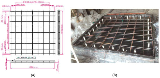
All slab specimens had dimensions of 1900 mm × 1900 mm × 105 mm and were internally reinforced with D10 rebars spaced at 240 mm in both directions, in accordance with general practices for flexural strengthening of concrete panels under dynamic loading [42,43]. The reinforcement cover was maintained at 20 mm, measured from the concrete surface to the outer face of the rebar. The reinforcement layout and specimen geometry are shown in Figure 1.
Figure 1.
Reinforcement details of slab specimens: (a) reinforcement layout and spacing; (b) completed reinforcement arrangement.
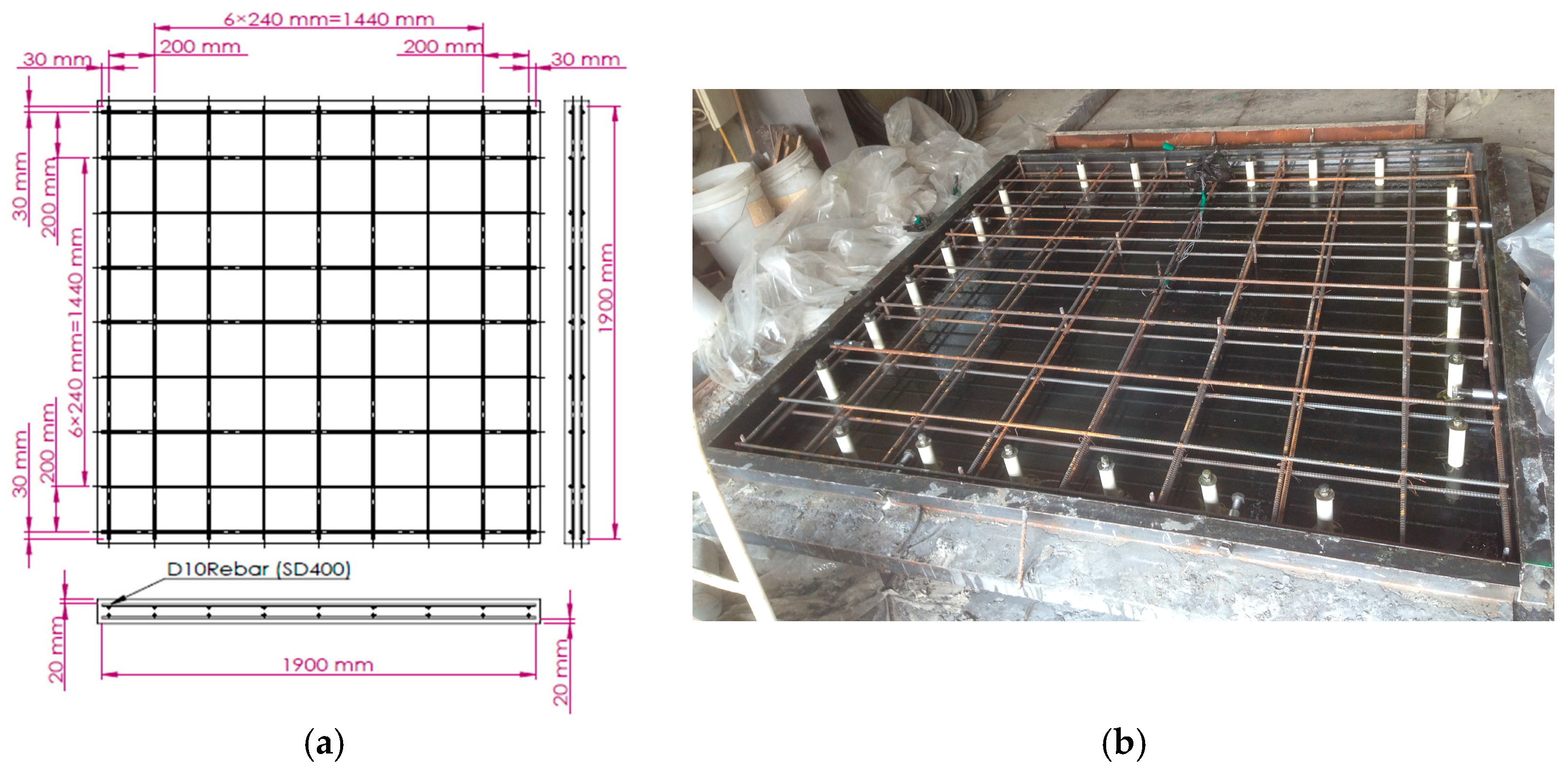
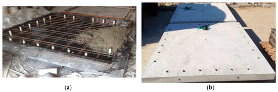
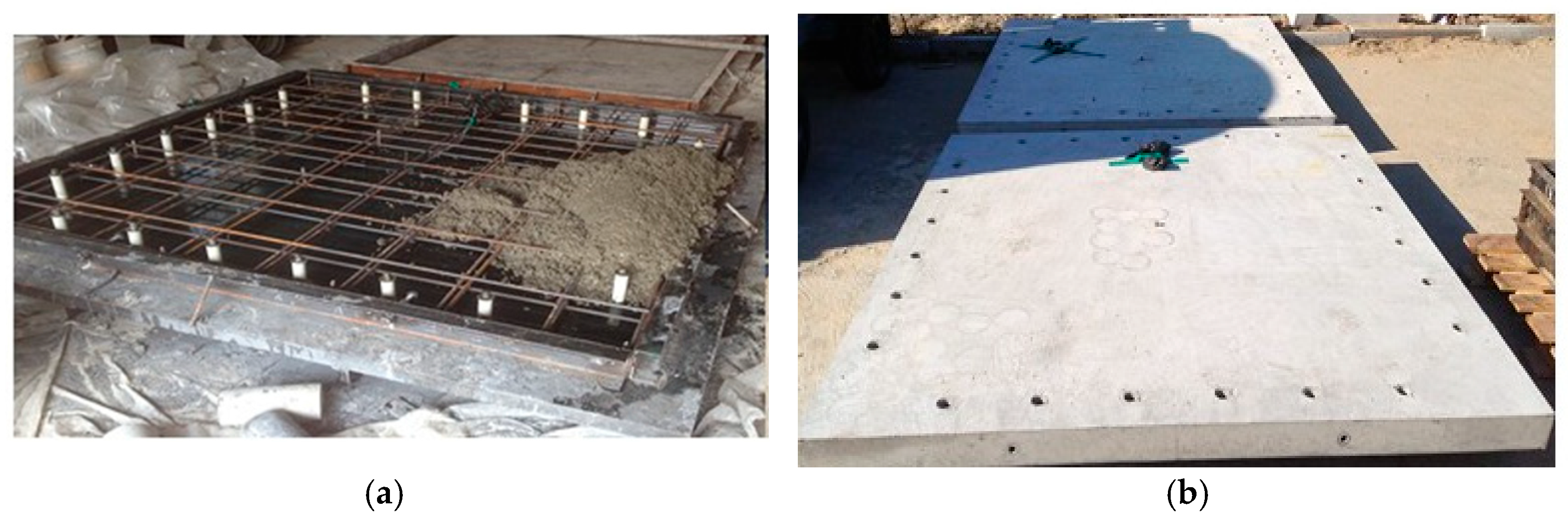
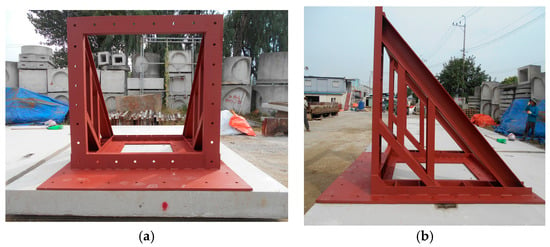
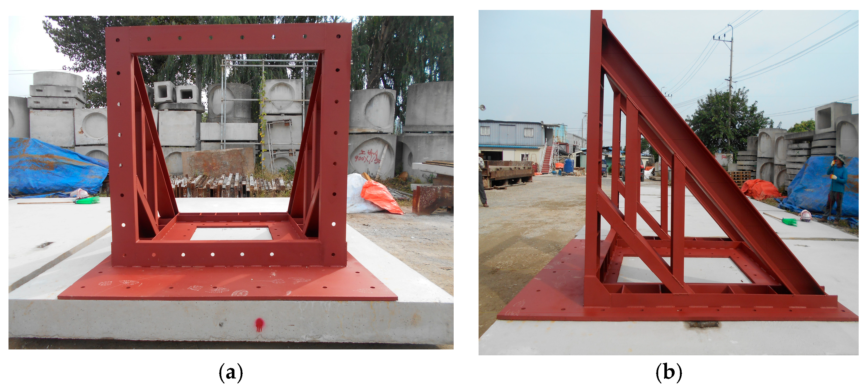
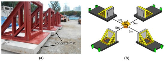
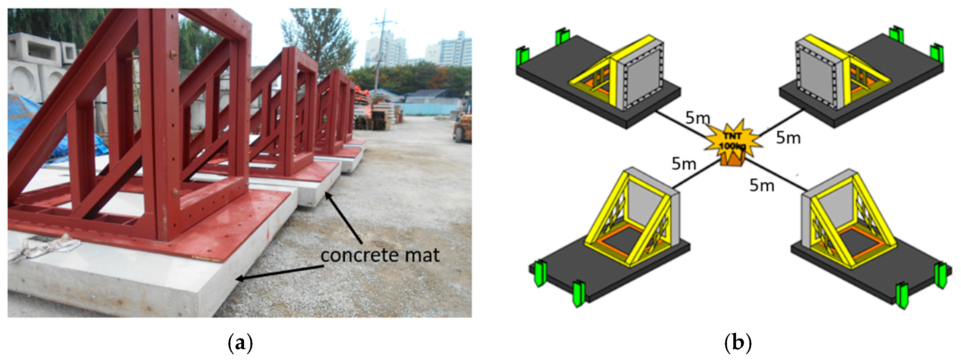
Before casting, 28 bolt holes were installed in each mold to anchor the specimens securely to the test frame. The manufacturing process of the slabs is illustrated in Figure 2. All specimens were poured, vibrated, and covered with plastic sheets for 24 h and then demolded and water-cured for 28 days at 20 ± 2 °C. A steel reaction frame fabricated from H-shaped steel sections, as shown in Figure 3, was used to hold each specimen during testing. The blast experiment set-up was designed to evaluate slab behavior under close-in detonation. Each specimen was rigidly fixed to the steel frame on all four edges using 28 high-strength bolts, leaving a 1500 × 1500 mm central area exposed to the blast. The frame was mounted on a 200 mm thick concrete mat, as shown in Figure 4a, to prevent unexpected displacement other than slab deformation. A 100 kg TNT charge was detonated at a 5 m stand-off distance from the slab center.
Figure 2.
Fabrication process of slab specimens: (a) installation of bolt holes; (b) finished slab specimen after production.
Figure 3.
Fixing frame for blast experiments: (a) front view; (b) side view.
Figure 4.
Blast experimental setup: (a) specimen support frame; (b) charge and specimen arrangement.
To ensure uniform exposure, all specimens were positioned at equal distances in four directions from the explosive, as illustrated in Figure 4a. The stand-off distance was measured from the bottom center of each slab to the charge center, and the TNT was elevated 6 inches above the ground to maintain consistent blast propagation, as shown in Figure 4b.
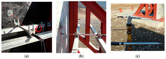
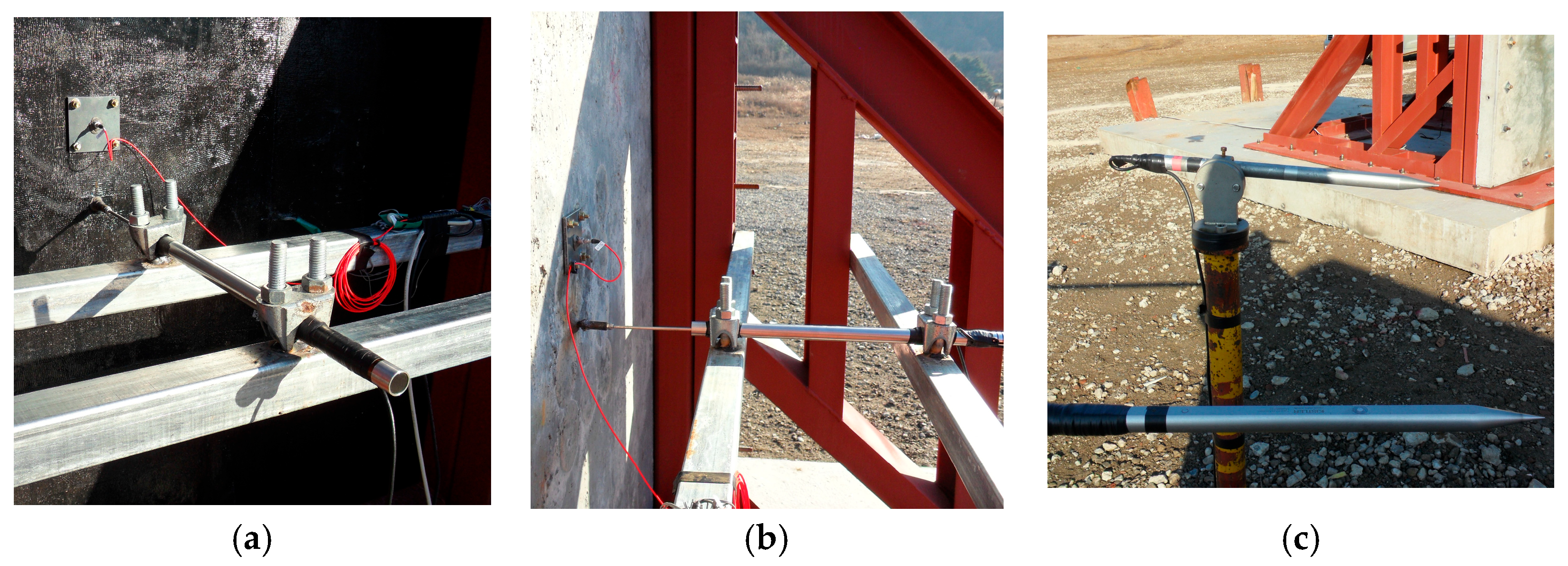
The blast experiments were conducted to evaluate the dynamic response and blast resistance of the four concrete slab specimens under controlled blast loading. The stand-off distance and TNT charge mass were determined based on preliminary blast analyses, which accounted for expected peak overpressure, impulse, and slab response to ensure that the applied load would generate measurable deformation without complete destruction of the reinforced specimens [44]. Each slab was placed vertically, and the rear face was anchored to a fixed cradle to prevent recoil displacement during detonation, ensuring accurate measurement of in-plane and out-of-plane responses. To measure structural response under blast loading, a linear variable displacement accelerometer gauge was installed near the slab center, as shown in Figure 5a,b, where the maximum deformation was expected. Pressure gauges were placed near the slab surfaces to measure the transient overpressure generated by the blast, as shown in Figure 5c. The slab dimensions adopted in this study were governed by the capacity of the supporting frame and the requirements of safe full-scale blast testing. Although the tested slabs were smaller than typical real-scale structural elements, they represent a structurally representative scale incorporating realistic boundary conditions, reinforcement details, and material behavior. It is noted that direct extrapolation of absolute response values to significantly larger slabs should be approached with caution due to potential scale effects. However, the comparative trends observed in terms of blast resistance enhancement due to fiber reinforcement and FRP strengthening are expected to remain valid when geometric similarity, reinforcement ratios, and material properties are maintained.
Figure 5.
Experimental instrumentation: (a) accelerometer and displacement sensor arrangement; (b) side view of sensor frame; (c) pressure transducer for blast overpressure.
3. Program of Numerical Investigation
The numerical investigation was carried out using a structured modeling framework consistent with experimental methodology. Three-dimensional models of the concrete slabs were developed, and appropriate material constitutive models were assigned for the concrete, fiber reinforcement, and FRP strengthening layers. A mesh sensitivity analysis was performed to ensure numerical accuracy and computational efficiency. Realistic boundary conditions were applied, and blast loading was simulated using CONWEP-based pressure–time histories within ANSYS Explicit Dynamics. Transient dynamic analyses were then conducted to capture the structural response. Numerical results, including displacement, acceleration, stress distribution, damage evolution, and energy absorption, were extracted and compared with experimental measurements for model validation. While material type and reinforcement configuration were varied to assess their influence on blast performance, the geometric dimensions, loading conditions, and boundary constraints were kept constant to ensure a consistent and meaningful comparison. A numerical investigation was conducted to analyze the deformation and damage progression of the slabs under blast loading. The study aimed to complement experimental observations and provide insight into internal stress–strain distributions that could not be measured directly. To accurately simulate structural responses, key modeling parameters, including material models, boundary conditions, and contact interactions, were carefully defined. All numerical simulations were performed using ANSYS Workbench-Explicit Dynamics, which is widely validated for predicting structural behavior under dynamic and blast loading conditions.
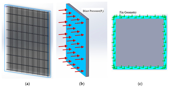
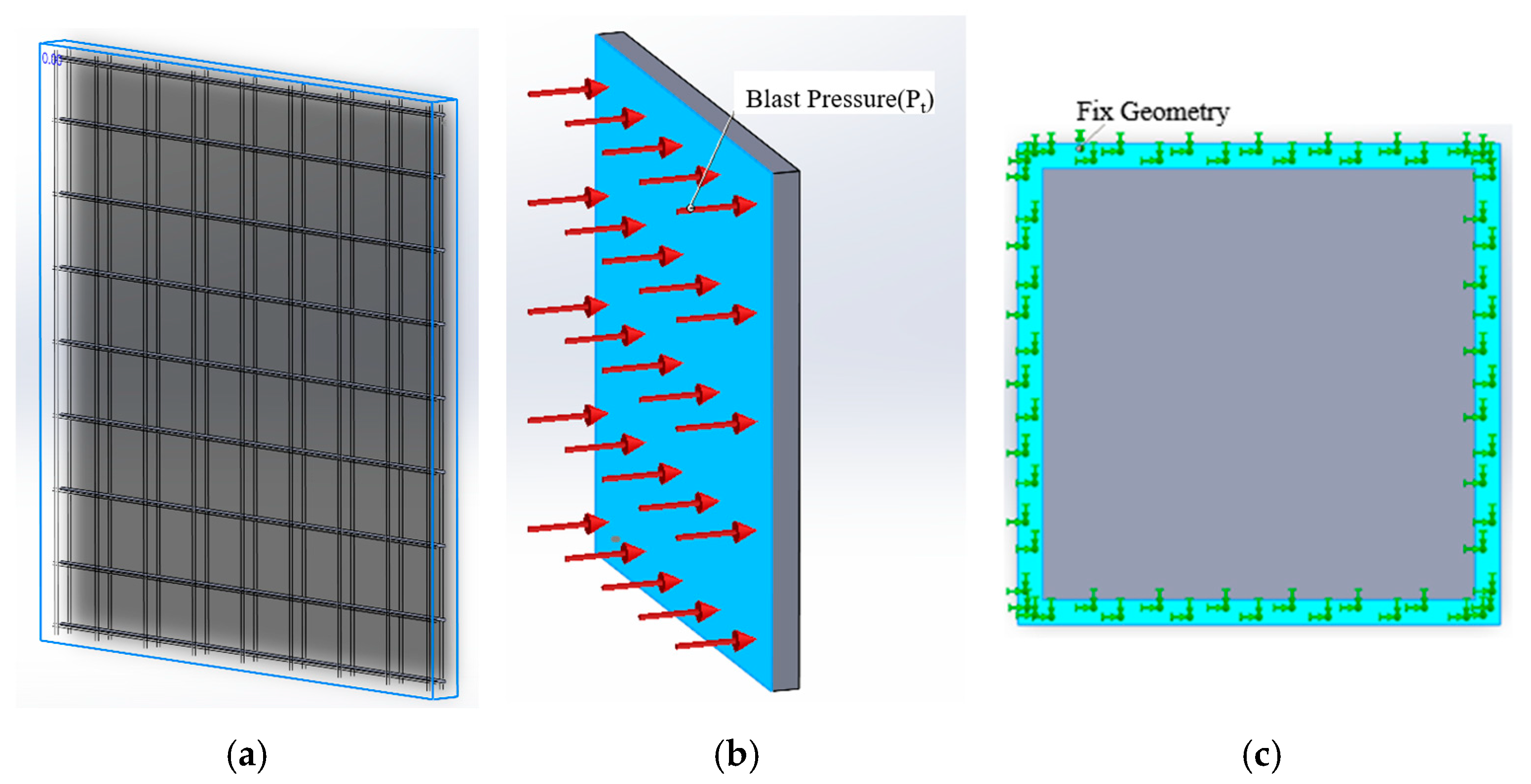
The finite-element (FE) models were first developed in ANSYS Design Modeler to generate the slab geometry and then imported into ANSYS Mechanical for numerical simulation. The slab geometry was modeled to replicate the experimental setup accurately, as illustrated in Figure 6a. The blast pressure loading, shown in Figure 6b, was applied using a pressure–time history derived from the Bulmash equations. The interaction between the concrete and steel reinforcement was modeled using the embedded region constraint in ANSYS, which defined the reinforcement as embedded rebar material to ensure proper bond behavior within the concrete matrix. The reinforcing steel bars were modeled using a bilinear isotropic hardening stress–strain relationship, which is commonly employed in explicit dynamic and blast analyses of reinforced concrete structures. The constitutive model consists of an initial linear elastic region followed by a plastic hardening branch after yielding. A Young modulus of 210 GPa and a yield strength of 400 MPa were adopted based on the material specifications of the reinforcement used in the experiments. Post-yield behavior was represented by a linear hardening modulus consistent with standard structural steel to ensure numerical stability and realistic post-yield response under high-strain-rate loading.
Figure 6.
Numerical model of slab specimen: (a) geometry and charge configuration; (b) boundary conditions; (c) reinforcement layout.
The interaction between the reinforcement and surrounding concrete was modeled using the embedded region constraint in ANSYS Explicit Dynamics, assuming perfect bond conditions. This assumption is considered appropriate for short-duration blast loading, where bond-slip effects are limited and inertial forces dominate the structural response. The adopted reinforcement constitutive model enables accurate representation of yielding, plastic deformation, and load transfer mechanisms observed in the experimental results. The material constitutive models for concrete and fiber-reinforced composites adopt nonlinear stress–strain relationships with post-peak softening to capture strength degradation. Stiffness deterioration and cumulative damage under cyclic or high-strain-rate loading are modeled using bilinear unloading–reloading paths, calibrated against experimental data. These hysteretic rules allow the finite-element simulations to realistically reproduce crack propagation, fiber pullout, and energy dissipation in reinforced and FRP-strengthened concrete slabs.
The specimen was modeled with fixed geometry, and all reinforcement bars were fully embedded to replicate the structural behavior under blast loading. An explicit FE method was used to simulate the blast loading, as it effectively handled large and rapid deformations while preventing excessive element distortion and maintaining positive element volumes throughout the analysis. The boundary conditions applied to the test specimen are illustrated in Figure 6c, where the steel rebars were fully fixed at the base, consistently with the experimental setup.
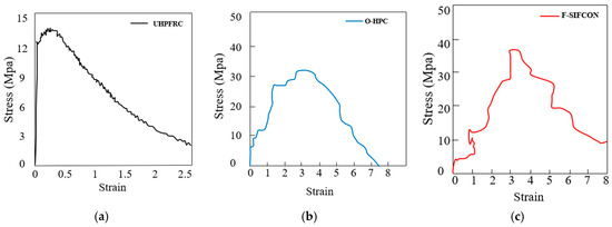
The slabs were made of NC, UHPFRC, O-HPC, and F-SIFCON, with all models using an isotropic and orthotropic nonlinear plastic material model available in ANSYS. The stress–strain curves adopted for UHPFRC, F-SIFCON, and O-UHPC under blast loading do not exhibit a well-defined linear elastic region.
This behavior is mainly attributed to the extremely high strain rates generated by blast pressure, which lead to rapid micro-crack initiation and an immediate nonlinear material response. Under such dynamic loading conditions, the elastic phase is very short and becomes indistinguishable from the subsequent nonlinear regime. The stress–strain relationships adopted for the concrete materials in the numerical model were based on calibrated constitutive models rather than purely theoretical assumptions. For normal concrete (NC), the constitutive relationship was adopted from the standard dynamic concrete material models available in ANSYS Explicit Dynamics and calibrated using the experimentally measured compressive strength obtained in this study.
For UHPFRC, O-HPC, and F-SIFCON, the stress–strain curves were developed based on a combination of (i) material properties obtained from experimental characterization tests conducted in this research, (ii) published experimental data on high-performance and fiber-reinforced concretes subjected to high-strain-rate and blast loading, and (iii) established constitutive modeling approaches commonly used in blast and impact simulations. As shown in Figure 7a, the tensile stress–strain curve of UHPFRC exhibits a smooth nonlinear increase in stress without a clear linear elastic segment. This response is caused by high-strain-rate effects, where micro-cracking initiates at very small strain levels. After crack initiation, steel fiber bridging contributes to a gradual stress development and enhanced tensile resistance under blast loading, reaching a maximum tensile stress of 12.5 MPa at a strain of 0.4.
Figure 7.
Dynamic stress–strain behavior under high-strain-rate loading: (a) UHPFRC, (b) O-HPC, and (c) F-SIFCON.
The O-UHPC stress–strain curve, presented in Figure 7b, demonstrates a controlled nonlinear response from the initial loading stage. The optimized fiber distribution promotes early stress redistribution and effective crack control, resulting in stable tensile behavior without a clearly separable elastic phase under dynamic loading. The maximum tensile stress attained is 13.5 MPa at a strain of 3.0. For F-SIFCON, the absence of a distinct elastic region is more pronounced due to its high fiber volume fraction, as illustrated in Figure 7c. Under high strain rates, stress is rapidly transferred from the cementitious matrix to the steel fibers, leading to immediate nonlinear behavior.
The stress–strain curve exhibits a sustained post-cracking response, indicating significant energy absorption and strong crack-bridging capacity under blast loading. The maximum tensile stress reaches 38 MPa at a strain of 3.5.
The steel reinforcement rebars were modeled using bi-linear isotropic hardening material behavior, with a Young modulus of 210 GPa. The tensile strength of the steel rebar was 360 MPa. All input parameters for the materials, including NC, UHPFRC, O-HPC, F-SIFCON, and steel reinforcement rebars, are summarized in Table 4. These parameters include the elastic modulus, compressive strength, fractured energy, and yield stress, providing a complete description of the FE model properties.
Table 4.
Material input parameters used in numerical modeling.
The blast load was simulated numerically using the Kingery–Bulmash empirical relations, which are widely adopted to predict free-field and reflected pressures from TNT explosions [45,46]. This experiment simulated a surface burst, in which reflected and incident shock waves combined to produce a strong, hemispherical pressure field acting approximately uniformly on the slab surface.
The pressure applied to the slabs was determined using the scaled distance (Z), calculated according to the empirical Kingery–Bulmash relations and the Hopkinson–Cranz law [47].
where is the stand-off distance (m) and is the TNT equivalent mass (kg). For this study, kg and , giving . The corresponding incident and reflected pressures were obtained from Kingery–Bulmash data.
According to Kingery–Bulmash empirical data, the shock front velocity (in m/s) can be approximated as following Equation (2):
Us—Shock front velocity (m/s).
Co—Ambient speed of sound (343 m/s).
Pi—Incident over pressure.
Po—Atmospheric pressure (101.32 kPa).
At , approximate .
Arrival time:
The blast pressure–time history can be described using the Friedlander equation, which characterizes the temporal decay of overpressure during the positive phase of an explosion. The equation is expressed as [48,49]
where is the pressure at time (kPa), is the peak incident pressure (kPa), is the positive-phase duration (ms), A is the decay coefficient (a dimensionless constant typically ranging between 1.6 and 2.2 for free-field explosions), and is the arrival time (ms).
Equation (4) is widely known as the Friedlander equation, which effectively characterizes the exponential decay of blast overpressure following the arrival of the shock front. The primary air blast parameters used in Equation (4), including the peak incident and reflected pressures, impulses, positive-phase duration, and arrival time, were obtained using the Kingery–Bulmash empirical correlations. These correlations were implemented in the Kingery–Bulmash blast parameter calculator, which was used to determine the parameters shown in Table 5. To better understand the influence of stand-off distance on the resulting blast parameters, a scaled distance diagram was generated using the Kingery–Bulmash empirical correlations.
Table 5.
Blast loading parameters for TNT detonation.
The scaled distance, defined as , where is the stand-off distance (m) and is the TNT equivalent weight (kg), is a key dimensionless parameter used to characterize blast intensity.
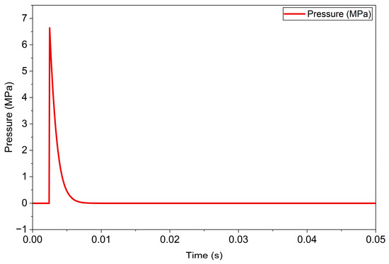
The blast wave parameters were extracted from the positive-phase shock wave characteristics of a TNT detonation at sea level, using the the graph of positive-phase shock wave parameters for TNT explosions at sea level [50], corresponding to a scaled ground distance of 1.08 m·kg−1/3. The analysis yielded a reflected overpressure of approximately 6645 kPa, representing the peak pressure acting on the surface during the positive phase of the blast wave.
To precisely capture the transient nature of the blast wave, the pressure–time history was generated using the Friedlander equation, which mathematically described the rapid rise and exponential decay of the reflected pressure following the shock front arrival. The Friedlander equation was employed to compute the blast pressure in each time step during the positive phase of the explosion. For simplified analyses, pre-determined tables of air blast parameters may also be used. Using these calculated values, a pressure–time load was generated in ANSYS Workbench Explicit Dynamics and applied to the front surface of the concrete slab to replicate the blast loading conditions. To experimentally investigate and gain a deeper understanding of the slabs’ dynamic behavior under blast loading, a numerical study was conducted using ANSYS Workbench Explicit Dynamics.
The simulation was designed to replicate the field blast conditions and validate the observed structural responses [51]. The analysis primarily focused on the time history of acceleration and maximum deformation for each slab type, which serve as key indicators of dynamic stiffness, energy absorption capacity, and overall blast resistance. Comparison between the simulated and experimental results allowed verification of the numerical model’s accuracy and provided detailed insight into the response characteristics of the various concrete compositions under extreme dynamic loads.
To experimentally investigate and evaluate internal stress–strain fields that could not be measured directly, finite-element models of each concrete slab were developed in ANSYS Workbench Explicit Dynamics [52,53]. The FE models accurately replicated the geometry of the tested slabs, with dimensions of 1900 × 1900 × 105 mm. Concrete was discretized using 8-node hexahedral solid elements to provide high-fidelity stress distribution, while the reinforcement bars were modeled as embedded beam elements, assuming a perfect bond with the surrounding concrete [54,55]. To improve accuracy near the blast-loaded surface, smaller elements of 50 mm were used, allowing the model to adequately capture the rapid stress variations induced by the blast [56].
The simulation duration included the positive phase of the blast and several milliseconds of subsequent structural response, ranging from 0.01 to 0.03 s. The key response variables (the key variables considered were t, representing time (s); Pr, the reflected pressure applied on the slab surface (MPa); u, the mid-span displacement (mm); a, the peak acceleration (g); σ, the stress in concrete and reinforcement (MPa); ε, the strain in concrete and reinforcement (%); E, the elastic modulus of steel reinforcement and FRP layers (GPa); and fy, the yield stress of reinforcement (MPa)) were monitored to validate numerical predictions against experimental results.
Bolt locations were constrained to replicate the experimental clamping configuration, ensuring realistic boundary behavior. Throughout the simulation, the overall energy balance, including internal, kinetic, and hourglass energies, was continuously monitored.
Validation was performed by comparing numerical predictions with experimental results in terms of mid-span deflection, peak acceleration, and failure patterns. The FE model reproduced the experimental response with good agreement, typically within ±10% for peak deflection, confirming its reliability for further internal-state analysis.
The applied reflected pressure–time history is illustrated in Figure 8, showing the temporal variation in load during the positive phase of the blast. The reflected pressure (Pr) and reflected impulse (Ir) are always greater than their corresponding incident values because the blast wave carries both pressure energy and kinetic energy. When the moving air particles in the shock front strike a rigid, immovable surface, their velocity is reduced to zero, causing the particles to compress and generate an additional pressure component. This interaction produces a substantial amplification of the load on the surface. As a result, the reflected pressure and impulse exceed the incident peak values [57].
Figure 8.
Reflected pressure–time history.
In ConWep-based blast analysis, the relationship between reflected pressure and incident side-on pressure varies with the scaled distance and the resulting shock overpressure. At large scaled distances, where the incident overpressure (Ps) is small relative to the ambient pressure (Po), the reflected pressure is approximately twice the incident value. As the scaled distance decreases and Ps becomes large compared to Po, typically for larger charges at close standoff distances, the reflected pressure increases nonlinearly and may reach up to eight times the incident side-on pressure, consistently with classical ConWep formulations.
In ANSYS Workbench-Explicit Dynamics, the blast pressure was applied as a time-dependent surface load on the front face of the slab specimens, representing the reflected overpressure generated by the TNT detonation. The magnitude and duration of the applied load were determined according to the equivalent TNT charge weight and standoff distance used in the experimental configuration [58]. The steel supporting stand was modeled as a rigid body to provide full reaction support and to eliminate undesired deformation during the numerical simulation.
Subsequently, numerical simulations were performed to evaluate the structural response of the slabs made with different concrete materials, NC, UHPFRC, O-HPC, and F-SIFCON, while maintaining the same TNT charge weight and blast distance. This approach allowed a direct comparison of the influence of material properties on deformation, acceleration response, reaction force, and failure behavior under identical blast loading conditions [59]. In addition to the reflected pressure on the slab surface, the incident pressure from the 100 kg TNT charge at a 5 m distance was also considered. Incident pressure was the blast pressure measured in free air before hitting any surface and provided the basis for calculating reflected pressure on the slab. While the slab response was mainly controlled by the reflected pressure, the incident pressure helped describe the overall blast environment.
4. Results and Discussion
4.1. Experimental Results
4.1.1. Experimental Displacement
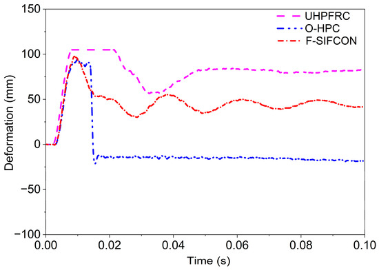
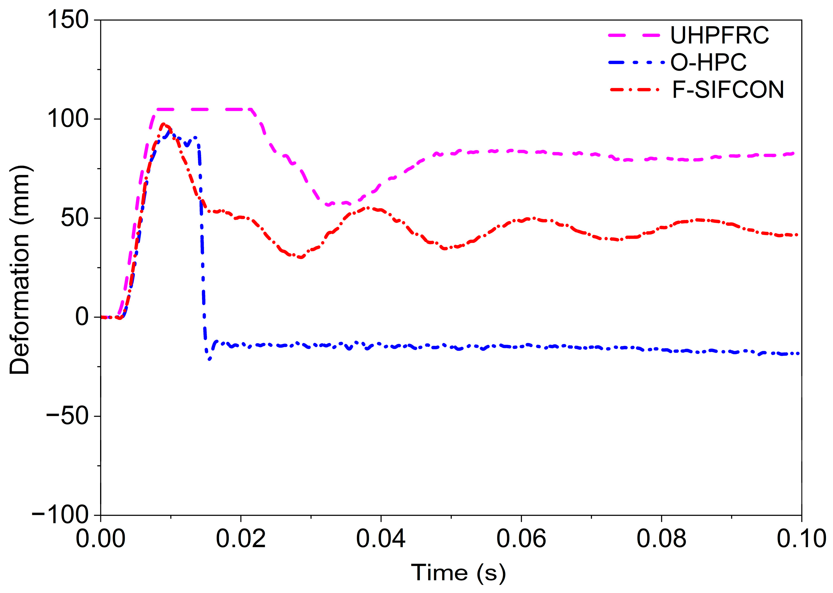
Figure 9 presents the experimental displacement responses of the slabs under blast loading. The NC specimen experienced complete structural failure under the 100 kg TNT charge, leaving only the reinforcement and preventing the recording of meaningful time history data [60]. This outcome is consistent with previously reported full-collapse behavior of normal-strength concrete subjected to similar blast intensities. For the remaining specimens, the peak displacements were 94.7 mm for O-HPC, 95.6 mm for F-SIFCON, and 104.6 mm for UHPFRC. While all specimens exhibited similar deformation trends during the early response phase (0.0024–0.0085 s), irregularities appeared in the post-peak region.
Figure 9.
Experimental displacement–time responses of UHPFRC, O-HPC, and F-SIFCON slabs.
In particular, the sudden negative displacement observed in O-HPC is attributed to temporary sensor disconnection or electrical noise induced by strong vibrations, rather than actual slab movement. However, before the peak displacement and the subsequent sudden negative drop, the comparison of maximum displacement values shows that the UHPFRC specimen exhibited the largest peak response, followed by O-HPC, while F-SIFCON recorded the lowest peak displacement among the three. In contrast, the F-SIFCON specimen exhibited a smooth and continuous displacement curve throughout the event, indicating stable sensor performance and more controlled structural deformation. The UHPFRC slab showed the highest peak displacement but reduced stability after the peak. Overall, the F-SIFCON system demonstrated the stable and reliable deformation response, likely due to the combined stiffness of the basalt FRP sheet and the ductility of the HPC matrix, making it the most effective configuration for blast resistance among the tested specimens.
4.1.2. Experimental Acceleration
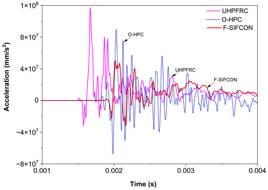
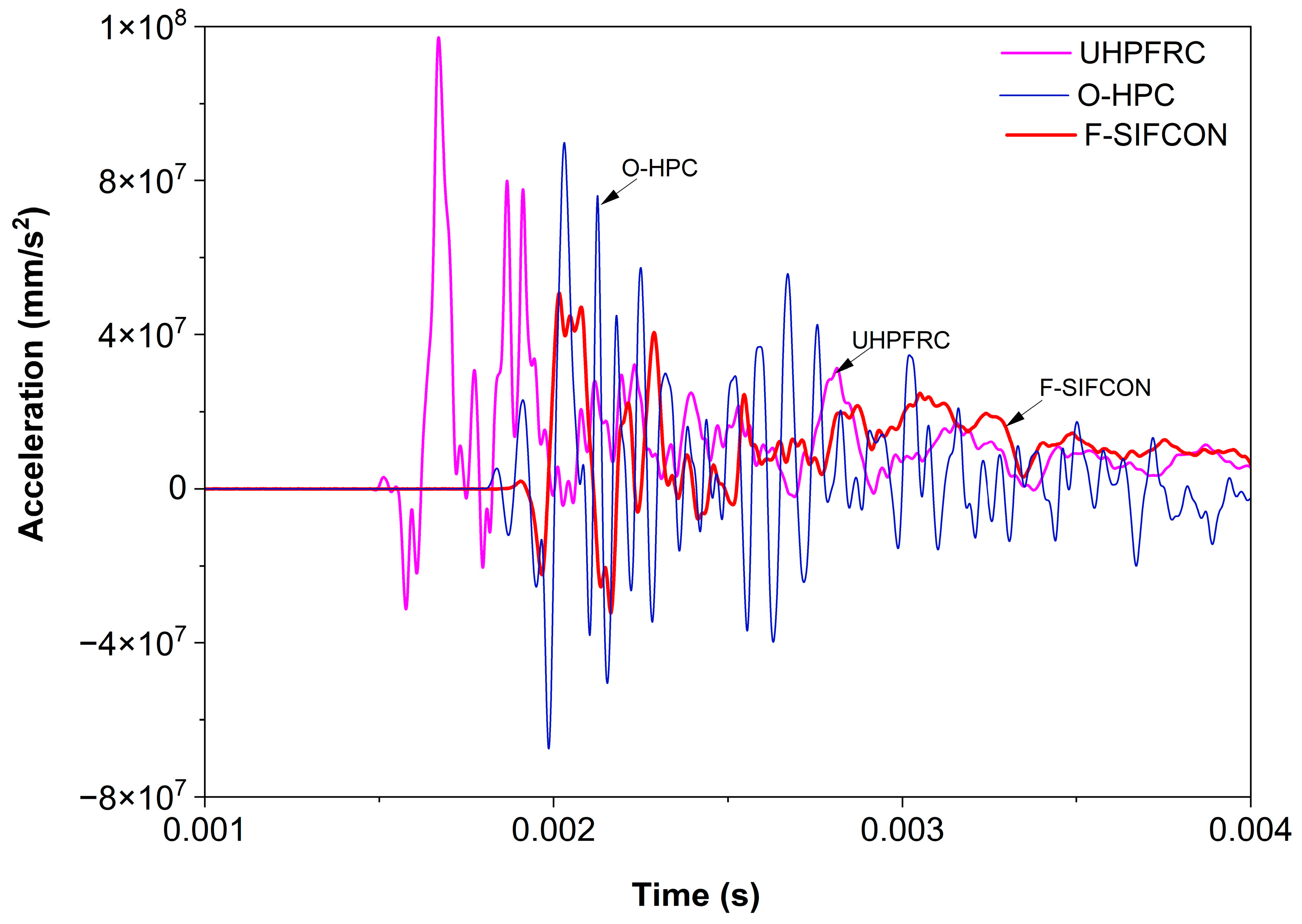
According to Figure 10, the experimentally measured peak accelerations for the slabs were 5.405 × 10⁷ m/s2 (F-SIFCON), 1.954 × 10⁷ m/s2 (UHPFRC), and 8.954 × 10⁷ m/s2 (O-HPC), recorded using three accelerometers mounted on each specimen. The NC specimens were destroyed during testing and the experimental data could not be recorded as a result.
Figure 10.
Experimental acceleration–time responses of UHPFRC, O-HPC, and F-SIFCON slabs under blast loading.
The UHPFRC accelerometer showed non-zero readings even before the TNT detonation, indicating sensor offset or pre-trigger errors, which may have affected the accuracy of the measured acceleration. Similarly, the O-HPC acceleration curve was irregular and did not follow a smooth trend corresponding to the applied blast pressure over time, suggesting possible sensor disconnection, poor mounting, or electrical noise during the high-frequency impact.
In contrast, the F-SIFCON specimen displayed a smooth and continuous acceleration response that closely followed the blast pressure–time history. This stability can be attributed to the high stiffness and structural integrity provided by the basalt FRP layers (E ≈ 48 GPa) combined with the HPC core. The robust material composition minimized local vibrations and excessive movement, allowing the accelerometers to capture accurate dynamic response data.
Overall, the experimental acceleration results indicate that F-SIFCON not only resisted blast-induced deformation effectively but also provided more reliable measurement conditions, whereas UHPFRC and O-HPC showed measurement errors likely caused by sensor limitations or material behavior under extreme high-strain-rate loading.
4.2. Numerical Results
4.2.1. Numerical Displacement
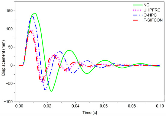
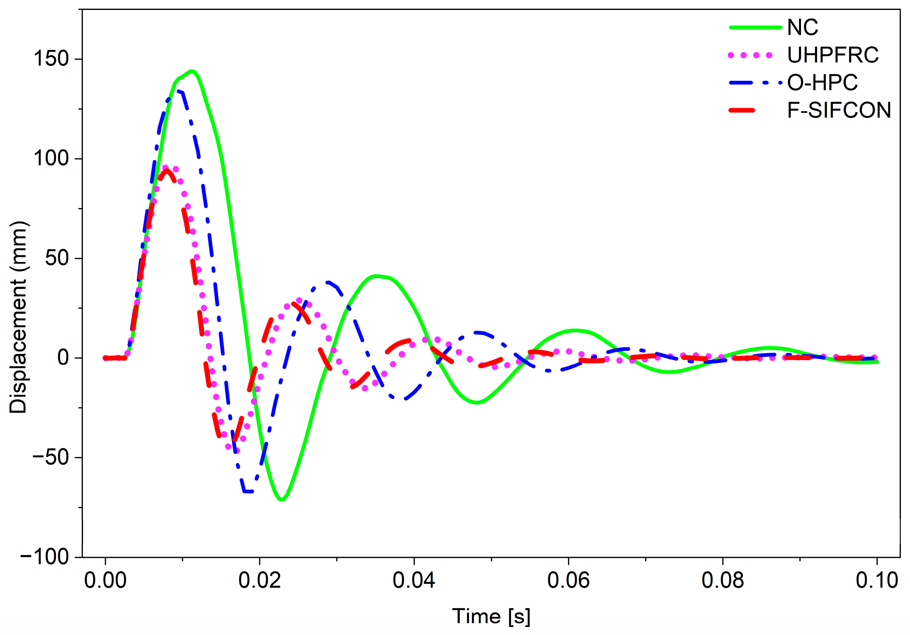
Figure 11 presents the displacement–time history curves obtained from the ANSYS numerical simulation for the four slab types subjected to identical blast loading conditions. The maximum mid-span displacements recorded were 143 mm for NC, 96 mm for UHPFRC, 134 mm for O-HPC, and 94 mm for F-SIFCON. As shown in Figure 11, all slabs exhibited a sharp rise in displacement immediately following the blast wave impact, followed by oscillations due to vibration and subsequent damping over time. The NC slab recorded the highest peak displacement, indicating severe deformation and limited resistance to the impulsive load. In contrast, the F-SIFCON slab showed the lowest peak displacement and the quickest stabilization, reflecting its superior stiffness and energy dissipation capacity.
Figure 11.
Displacement distributions from ANSYS simulation for NC, UHPFRC, O-HPC, and F-SIFCON slabs under blast loading.
The improved performance of F-SIFCON is primarily attributed to its composite configuration and superior material properties. With the highest Young modulus (48 GPa) and a moderate density (2200 kg/m3), this specimen demonstrated high rigidity and resistance to flexural deformation. The addition of two basalt FRP sheets provided significant confinement, effectively reducing crack propagation and improving load transfer during the dynamic event. The FRP strengthening also contributed to better post-blast recovery, as evident from the reduced amplitude and shorter vibration duration in the displacement–time curve.
In contrast, the NC slab (E = 30 GPa; ρ = 2500 kg/m3) showed the largest displacement due to its brittle behavior and lack of reinforcement beyond steel bars. The UHPC slab (E = 45 MPa) displayed improved performance due to the crack-bridging action of steel fibers, while the O-HPC (E = 27.7 GPa; ρ = 2000 kg/m3) exhibited slightly higher displacement, reflecting the lower stiffness of organic fibers despite their ductility and energy absorption benefits.
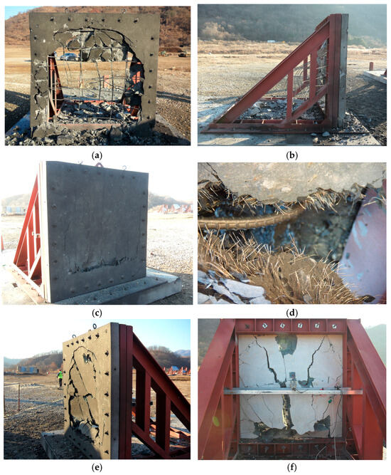
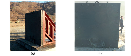
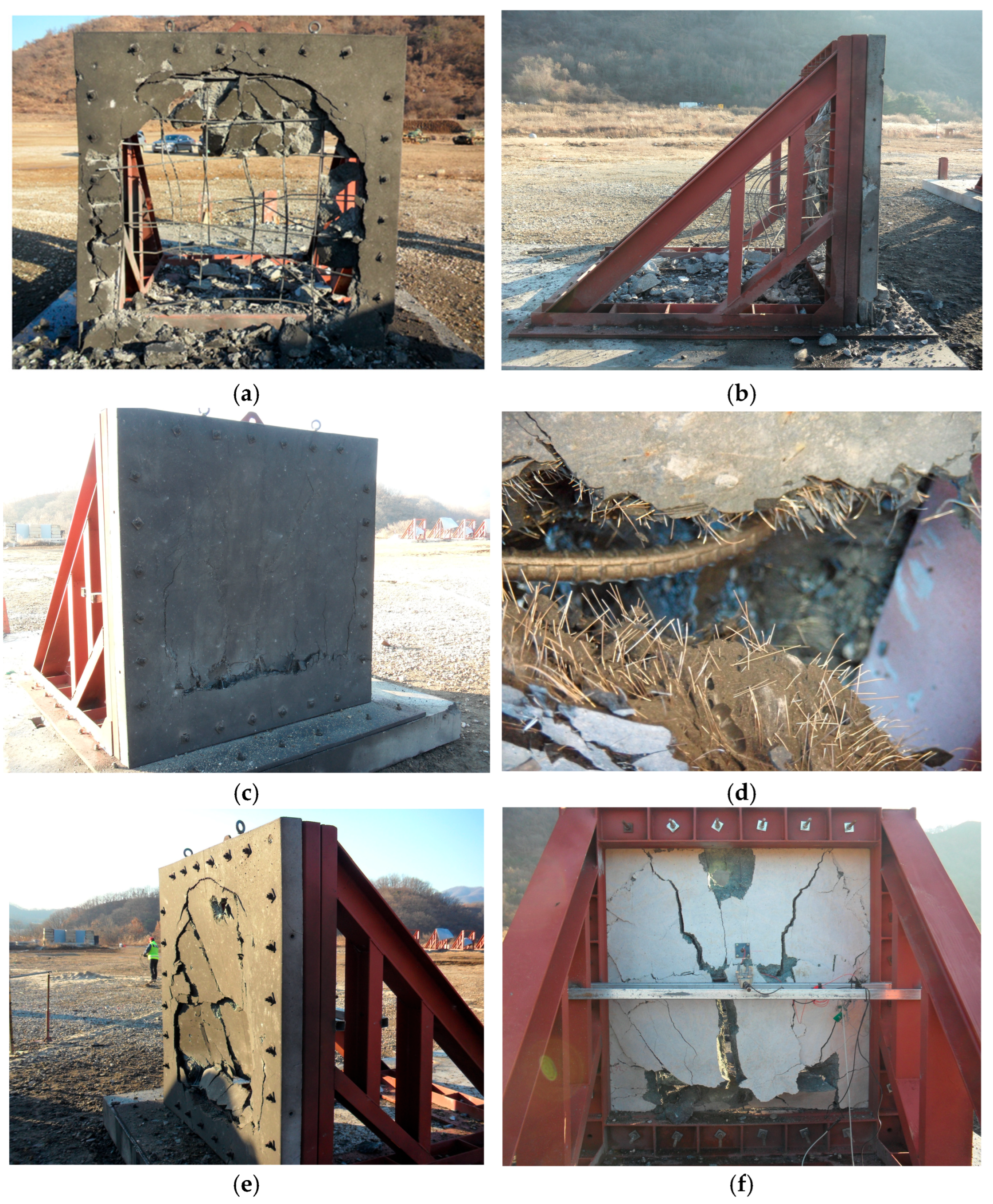
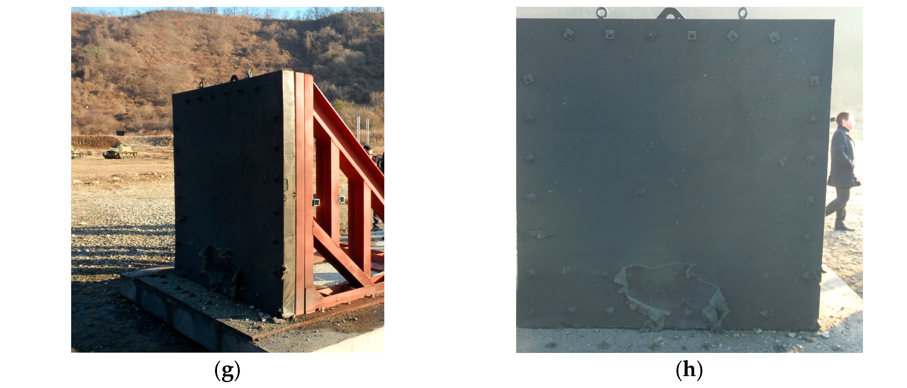
During the experimental investigation, the NC slab was completely destroyed by the blast, as shown in Figure 12a,b, leaving only the exposed reinforcement. Because of this total structural failure, no displacement measurements could be recorded for the NC specimen. For the remaining specimens, detailed post-blast photographs were captured from multiple views, including the front (blast-facing) and rear (scabbing) sides. Figure 12c shows fiber pullout in the O-HPC specimen, while Figure 12d presents the front view of the UHPFRC slab.
Figure 12.
Experimental damage specimens: (a) NC specimen front view; (b) NC specimen side view; (c) UHPFRC front view; (d) fiber pull-out after blast; (e) O-HPC front view; (f) O-HPC back view; (g) F-SIFCON side view; (h) F-SIFCON front view.
Figure 12e,f show the front and back faces of the O-HPC slab with visible cracking, and Figure 12g,h illustrate the side and front views of the F-SIFCON specimen and its crack patterns. These photographs provide a clear comparison of crack development, crack width, fiber pullout behavior, and overall damage severity among the tested slabs. Overall, the displacement analysis confirms that F-SIFCON (HPC + two basalt FRP sheets) exhibited the blast resistance, achieving approximately a 47% reduction in maximum displacement compared with NC. The combined effect of fiber reinforcement and external basalt FRP strengthening significantly enhanced the deformation control and structural resilience of the slab under blast loading conditions.
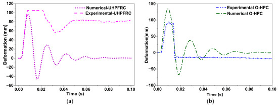
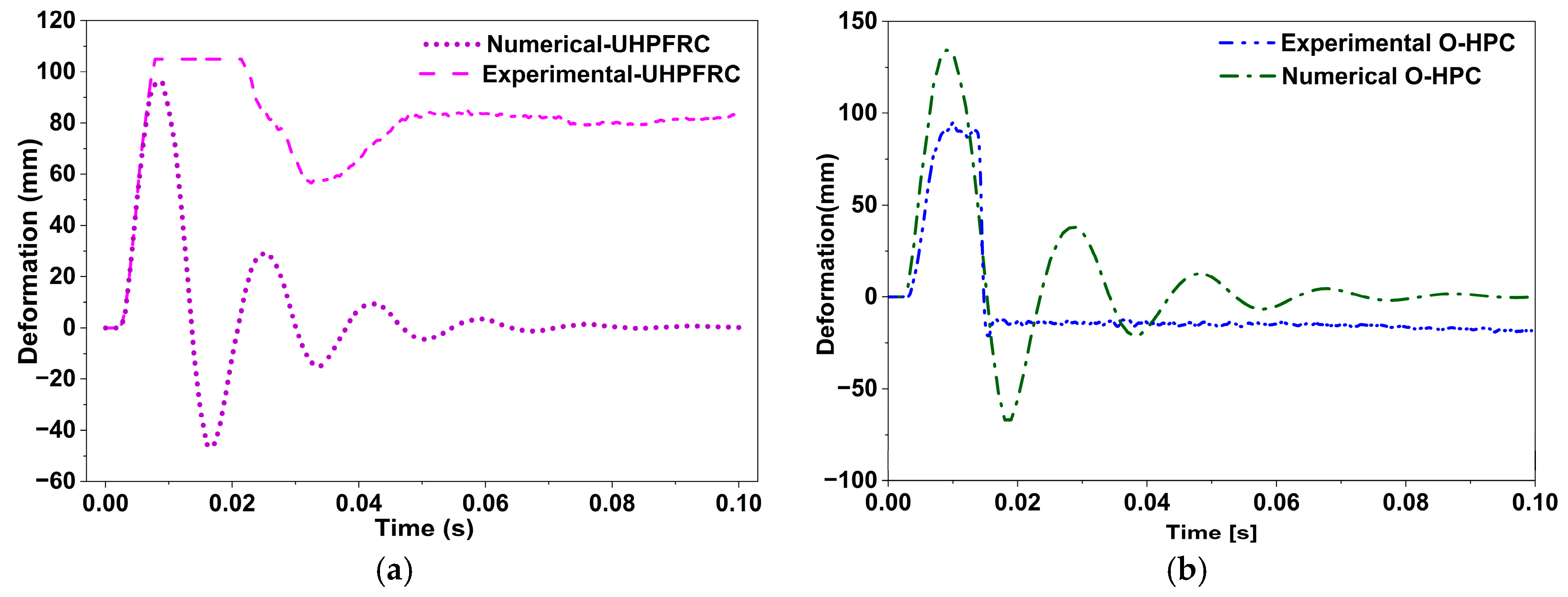
A comparative analysis was conducted between experimental and finite-element (FE) simulation results to validate the model’s accuracy in predicting slab deformation under blast loading. The displacement results for all four slab types demonstrated consistent trends between experimental and numerical data, confirming the reliability of the ANSYS model in capturing the dynamic behavior of various concrete compositions.
For the NC slab, displacement was not recorded experimentally due to complete structural failure, which agreed with the simulation results, indicating severe deformation and instability. The UHPFRC slab exhibited close agreement, with experimental and numerical displacements of 105 mm and 96 mm, as shown in Figure 13a, respectively. The minor deviation was likely due to a transient sensor delay during the initial blast phase.
Figure 13.
Comparison of numerical and experimental displacement responses of fiber-reinforced slabs: (a) UHPFRC; (b) O-HPC; (c) F-SIFCON; (d) combined displacement results.
In the O-HPC slab, the experimental displacement (112 mm) slightly exceeded the simulated value (134 mm), as shown in Figure 13b, primarily due to variability in fiber distribution and the strain-rate sensitivity of aramid fibers. Similarly, for the F-SIFCON slab, the experimental displacement (95.6 mm) was slightly higher than the simulated value (94 mm), as shown in Figure 13c, with the small difference attributed to local interface effects, such as minor slip or delamination, while the overall response remained governed by the material behavior.
In the finite-element analysis, the rebar was modeled using embedded region constraints to represent the interaction between concrete and steel reinforcement for all specimens. This modeling approach allowed the observed displacement and failure responses to be attributed primarily to the material behavior rather than interface issues.
The combined experimental displacement results for all three slab types, shown in Figure 13d, demonstrate the accuracy of the numerical model in capturing slab deformation. Overall, the finite-element simulation successfully represented the structural response under blast loading, with all deviations remaining within acceptable limits. The observed differences can be attributed to instrumental delays, variability in fiber orientation, and the simplified modeling of interfaces, which are common factors in high-strain-rate impact analyses.
4.2.2. Numerical Acceleration
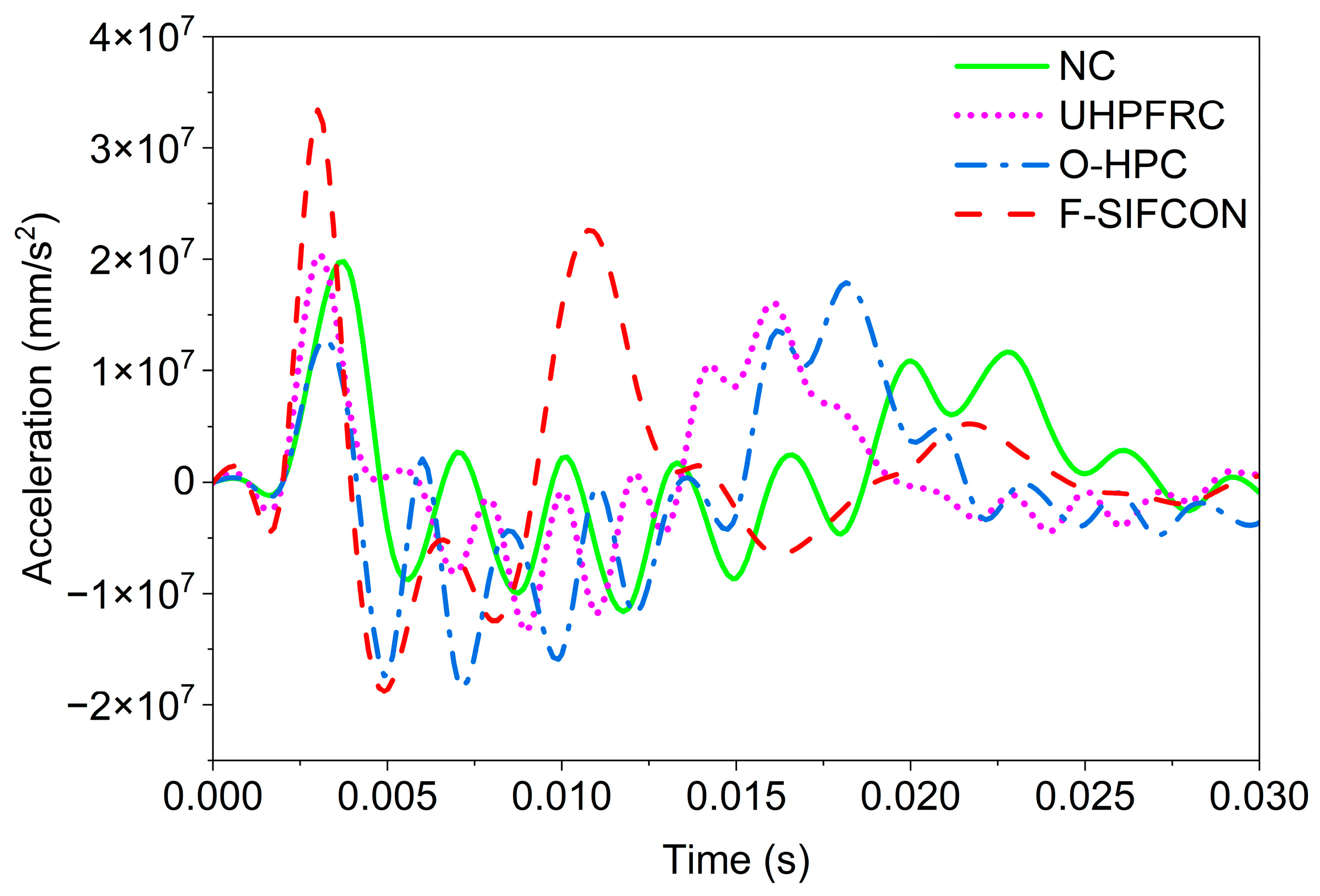
Figure 14 presents the acceleration–time responses obtained from the ANSYS numerical simulation for the four slab types subjected to identical blast loading conditions. The peak acceleration values recorded were 1.41 × 107 mm/s2 for normal concrete (NC), 2.05 × 107 mm/s2 for UHPFRC, 1.21 × 107 mm/s2 for O-HPC, and 3.34 × 107 mm/s2 for F-SIFCON.
Figure 14.
Dynamic acceleration profiles of all slab types.
The comparative results indicate that the F-SIFCON slab exhibited a greater acceleration response than the other specimens, suggesting that it possesses higher stiffness and a higher natural frequency under blast loading conditions. This slab, composed of high-performance fiber-reinforced concrete (compressive strength 80 MPa; Vf = 5% with 75 mm steel fibers) and strengthened with two external basalt FRP sheets, demonstrated superior resistance to blast-induced deformation. The combination of a high elastic modulus and moderate density (2200 kg/m3) enabled the F-SIFCON slab to transfer and dissipate blast energy more effectively, resulting in rapid oscillation but lower permanent deformation.
In contrast, the NC slab, with a compressive strength of 27 MPa, density of 2500 kg/m3, and elastic modulus of 30 MPa, recorded the lowest peak acceleration. This behavior reflects its low stiffness and brittle nature, which leads to significant deformation and slower dynamic response under impulsive loads. The low acceleration of NC is consistent with its high displacement value and complete failure observed in the experimental test, where only the steel reinforcement remained after detonation.
The UHPFRC slab (compressive strength: 180 MPa; 2% steel fibers; 19.5 mm length; E = 45 MPa) showed a substantial increase in acceleration compared with NC, primarily due to the enhanced matrix strength and the bridging action of short steel fibers that improved load transfer and cracking resistance. The O-HPC slab (compressive strength: 80 MPa; 1.5% aramid fibers; E = 27.7 MPa; ρ = 2000 kg/m3) exhibited slightly higher acceleration than S-UHPC despite its lower stiffness, which can be attributed to its lower density and better energy absorption capacity due to the flexible nature of organic fibers.
Overall, the acceleration results confirm that stiffer materials with higher fiber volume fractions and FRP confinement exhibit greater peak acceleration responses, corresponding to stronger resistance against blast-induced flexural deformation. The F-SIFCON slab, combining steel fiber reinforcement with external basalt FRP strengthening, clearly demonstrates the most efficient dynamic response and superior blast resistance among the studied specimens.
4.2.3. Reaction Force
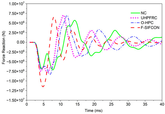
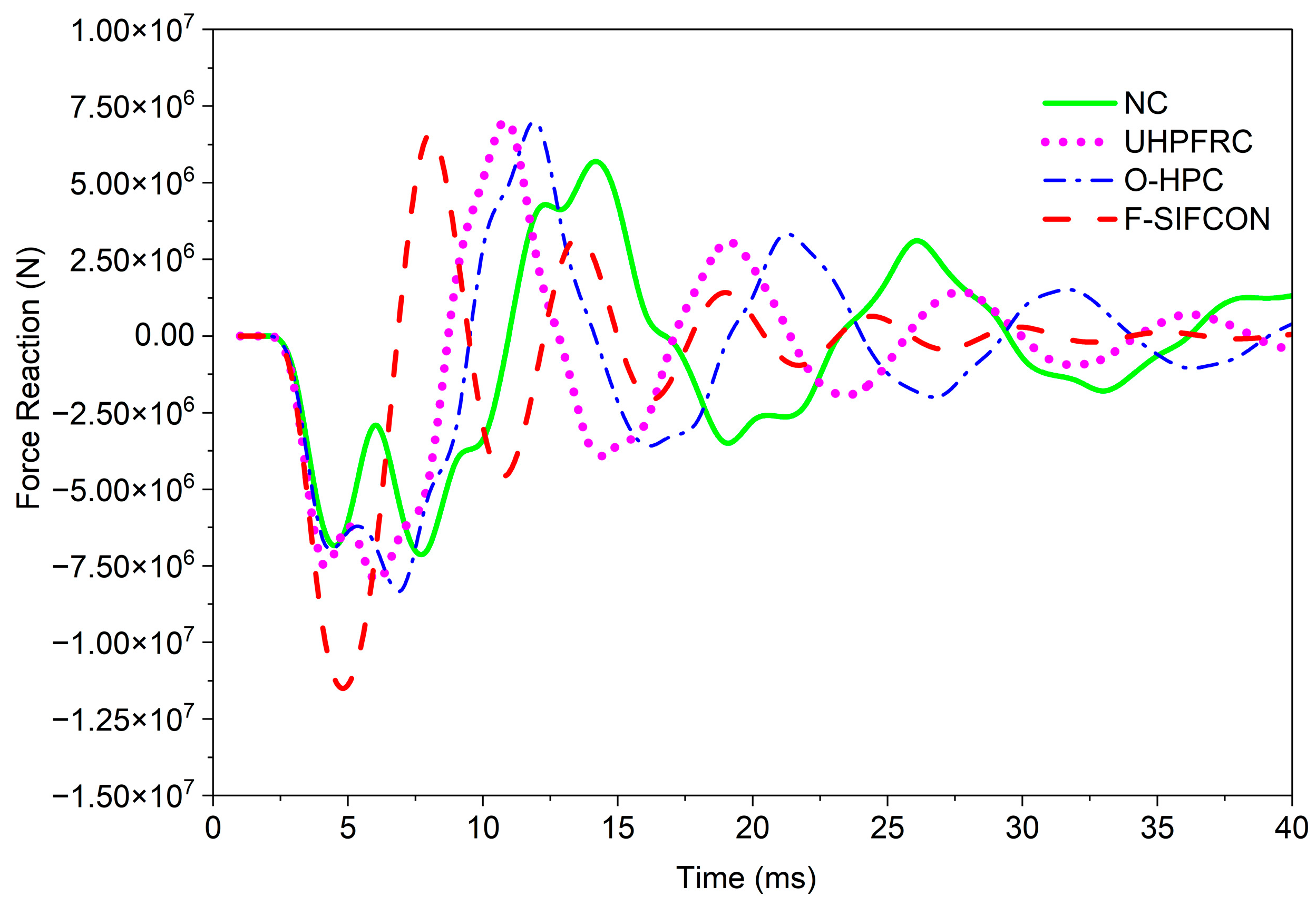
The reaction force represents the total resisting force developed at the supports during the blast event, reflecting how effectively each slab configuration can transfer and dissipate impact energy. The ANSYS simulation results for each slab type are illustrated in Figure 15, showing the time-dependent variation in reaction force for NC, UHPFRC, O-HPC, and F-SIFCON.
Figure 15.
Reaction force responses of all slab types under blast loading.
The peak reaction forces obtained from the simulation were 12.36 × 10⁶ N for F-SIFCON, 10.61 × 10⁶ N for UHPFRC, 9.81 × 10⁶ N for O-HPC, and 7.92 × 10⁶ N for NC. The results reveal that the inclusion of fiber reinforcement and external confinement considerably increased the load resistance capacity of the slabs.
The NC slab, with the lowest compressive strength (27 MPa) and Young modulus (30 GPa), exhibited the lowest reaction force. This behavior can be attributed to its brittle failure mode and limited energy absorption capacity. Under blast loading, NC tends to undergo rapid cracking and localized damage, resulting in early stiffness degradation and a smaller overall reaction force at the supports.
In comparison, the UHPFRC (compressive strength: 180 MPa; E = 45 GPa) and O-HPC (compressive strength: 80 MPa; E = 27.7 GPa) specimens showed higher reaction forces, owing to their improved ductility and fiber bridging mechanisms. The inclusion of fibers enabled better stress redistribution and delayed crack propagation, enhancing stiffness retention and energy dissipation during the blast response.
Among all specimens, the F-SIFCON slab, which integrates two layers of basalt FRP sheets bonded to an HPC core, demonstrated the highest peak reaction force (12.36 × 10⁶ N). The superior performance of this hybrid composite can be attributed to the synergistic action between the FRP confinement and internal steel fibers (Vf = 5%), which enhance structural stiffness, limit deformation, and improve blast energy absorption. This configuration provides a more uniform stress distribution and improves structural integrity under dynamic loading.
The reaction force–time curves in Figure 15 further illustrate that the F-SIFCON slab experienced smoother load transitions and fewer abrupt force spikes compared to the other specimens. These findings confirm that the combination of FRP confinement and fiber reinforcement effectively mitigates stress concentrations, leading to enhanced blast resistance and overall global stability of the structural system.
4.2.4. Energy
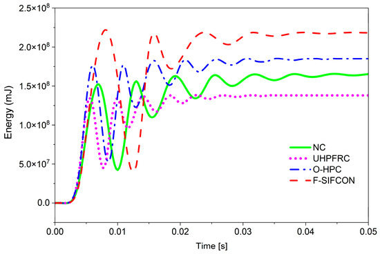
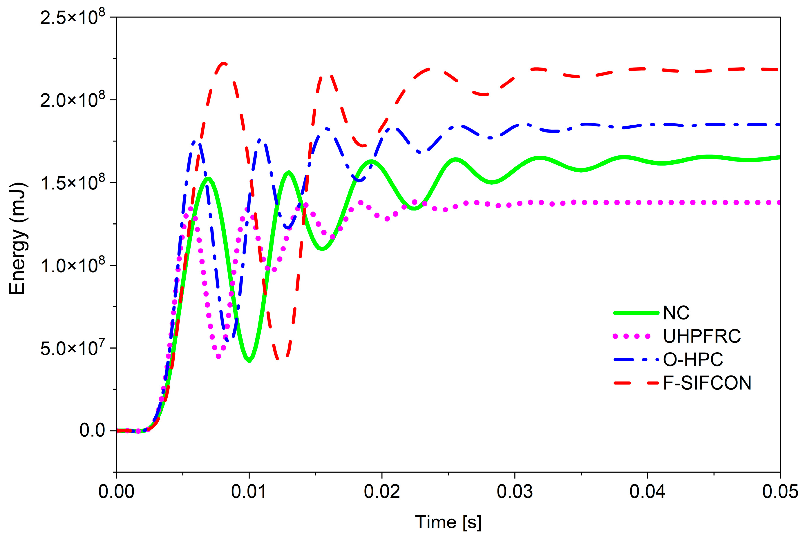
Internal energy represents the total strain energy absorbed by the slab during blast loading, primarily due to deformation, cracking, and material damage. It is a crucial parameter in evaluating the energy absorption and dissipation capacity of different concrete types under extreme dynamic loads. The variation in internal energy for the four slab configurations, NC, UHPFRC, O-HPC, and F-SIFCON, is presented in Figure 16.
Figure 16.
Internal energy–time histories of all slab specimens.
The F-SIFCON slab exhibited the highest peak internal energy (236,230 J), indicating a greater ability to absorb blast-induced energy compared with the other specimens. This performance is attributed to the combined contribution of its densely packed steel fiber matrix and the confinement provided by the externally bonded basalt FRP sheets.
Furthermore, the externally bonded basalt FRP sheets significantly improve the flexural stiffness and confinement effect of the composite system. The high elastic modulus of the BFRP layers (E = 90 GPa) enhances the slab’s tensile resistance on the tension face, reducing surface spalling and delamination. The strong bond between the FRP sheets and the concrete substrate allows for composite action, in which both materials deform together and share the load efficiently. As a result, the blast energy is more effectively absorbed through elastic strain storage and distributed deformation rather than localized cracking or fragmentation.
The combination of high stiffness, ductility, and strong interfacial bonding results in an optimal balance between energy storage and dissipation. This explains the significantly higher internal energy observed in the F-SIFCON slab compared to other concrete types. Therefore, the F-SIFCON slab demonstrated the best blast resistance characteristics, with improved crack control, reduced surface damage, and superior energy absorption capability under high-strain-rate loading conditions.
The basalt FRP sheet attached to the concrete surface helps the slab become more flexible and absorb more blast energy by allowing it to deform in a controlled way instead of breaking suddenly. The strong bond between the FRP sheet and the concrete also makes the slab stiffer and spreads the stress more evenly, which reduces local damage and surface cracking. The higher internal energy value from the simulation shows that the strengthened slab absorbed more of the blast energy through material deformation and damping. This means the basalt FRP-strengthened high-performance concrete slab can better reduce the impact of the blast and prevent serious damage compared to normal or unreinforced concrete slabs.
Table 6 summarizes the key numerical results for all four slab types under blast loading, including peak displacement, acceleration, reaction force, and internal energy. The NC slab exhibited the highest peak displacement (143 mm) and reaction force (12.36 × 10⁶ N), reflecting its brittle behavior and poor blast resistance. The incorporation of steel fibers in UHPFRC and organic fibers in O-HPC improved the dynamic response, reducing displacement and reaction force while providing better energy absorption. Among all specimens, the F-SIFCON slab, strengthened with two layers of basalt FRP, demonstrated the best overall performance, with the lowest peak displacement (76 mm), highest acceleration (3.34 × 107 mm/s2), and maximum internal energy (236,230 J). These results indicate that combining fiber reinforcement with FRP confinement significantly enhances the blast resistance and structural resilience of concrete slabs.
Table 6.
Numerical results of dynamic responses under blast loading.
4.3. Discussion
The experimental and numerical results clearly demonstrate distinct blast response behaviors among the four slab systems investigated: normal concrete (NC), ultra-high-performance fiber-reinforced concrete (UHPFRC), organic fiber-reinforced high-performance concrete (O-HPC), and basalt FRP-strengthened slurry-infiltrated fiber concrete (F-SIFCON). The NC slab experienced complete structural collapse under the 100 kg TNT blast, which is consistent with previous studies reporting the brittle failure and limited energy absorption capacity of conventional reinforced concrete subjected to high-intensity blast loading. This observation confirms that conventionally reinforced concrete slabs are inadequate for resisting extreme dynamic loads and highlights the necessity of advanced reinforcement strategies.
Among the enhanced slab systems, the F-SIFCON slab exhibited the most stable and effective blast-resistant performance. Experimentally, F-SIFCON recorded the lowest peak displacement (95.6 mm), the highest acceleration response (5.405 × 10⁷ m/s2), and the maximum internal energy absorption (236 kJ). These trends were closely reproduced by the numerical simulations, which predicted a peak displacement of 94 mm and comparable reaction force levels. The close agreement between experimental and numerical results confirms the reliability of the finite-element model in capturing the dynamic response of fiber- and FRP-reinforced concrete slabs under blast loading. Minor discrepancies are attributed to unavoidable experimental uncertainties such as sensor delays, local interface effects, and fiber orientation variability, which are commonly reported in high-strain-rate blast experiments.
The superior performance of the F-SIFCON system can be attributed to the synergistic interaction between the high-performance concrete matrix with embedded steel fibers and the externally bonded basalt FRP layers. The steel fibers enhance ductility through crack-bridging mechanisms, delay crack propagation, and improve post-peak stability, while the basalt FRP sheets increase flexural stiffness, provide confinement, and promote more uniform stress distribution across the slab surface. This hybrid reinforcement mechanism results in smoother displacement and acceleration histories, higher reaction forces, and significantly improved energy absorption compared with slabs reinforced solely with fibers. Similar benefits of fiber reinforcement and FRP confinement have been reported independently in earlier studies; however, their combined effect is shown here to be particularly effective under severe blast loading.
In contrast, the UHPFRC slab demonstrated improved blast resistance compared with NC but exhibited relatively higher peak displacement and post-peak instability. This behavior is consistent with previous findings that, although UHPFRC provides high strength and crack resistance, its response under extreme dynamic loading can still be governed by stiffness degradation after peak response. The O-HPC slab showed moderate displacement reduction and energy absorption benefits due to the flexible nature of organic fibers; however, its lower elastic modulus resulted in reduced stiffness and less effective deformation control. Similar trends have been reported in earlier investigations of organic fiber-reinforced concretes subjected to impact and blast loading.
A key novelty of the present study lies in the unified experimental–numerical framework used to directly compare multiple reinforcement strategies under identical blast loading conditions. While many previous studies have focused on either fiber-reinforced concrete or FRP-strengthened concrete individually, few investigations provide a systematic comparison of conventional concrete, fiber-reinforced systems, and hybrid fiber–FRP configurations validated through both experiments and numerical simulations. The results demonstrate that the F-SIFCON slab achieved up to a 47% reduction in maximum displacement and a substantial increase in internal energy absorption compared with NC, clearly highlighting the effectiveness of hybrid reinforcement in enhancing blast resistance.
The reaction force and energy absorption analyses further confirm the advantages of the hybrid system. The F-SIFCON slab developed the highest peak reaction force (12.36 × 10⁶ N), indicating superior load transfer capacity and structural integrity under impulsive loading. In contrast, the NC slab exhibited the lowest reaction force due to rapid stiffness degradation and brittle failure, while UHPFRC and O-HPC showed intermediate responses associated with improved ductility and fiber-bridging effects. The significantly higher internal energy absorbed by F-SIFCON demonstrates its ability to dissipate blast energy through controlled deformation rather than localized cracking or catastrophic failure.
5. Conclusions
Based on the experimental and numerical investigations conducted on blast-loaded concrete slabs with different reinforcement strategies, the following conclusions are drawn:
- Blast performance of normal concrete: The normal concrete (NC) slab experienced severe structural collapse under the 100 kg TNT blast due to its brittle behavior and limited energy absorption capacity, confirming its poor resistance to impulsive loading.
- Effect of fiber reinforcement: The UHPFRC and O-HPC slabs exhibited significantly improved blast resistance compared with NC, owing to fiber bridging mechanisms that enhanced ductility, stiffness retention, and deformation control under high-strain-rate loading.
- Performance of hybrid reinforcement (F-SIFCON): The F-SIFCON slab demonstrated the best overall blast performance, characterized by the smallest mid-span displacement, the highest internal energy absorption, and the most stable post-blast response among all tested specimens.
- Role of FRP confinement: The combined action of internal steel fibers and external basalt FRP sheets effectively enhanced structural stiffness, delayed crack initiation and propagation, prevented localized damage, and promoted ductile energy dissipation.
- Experimental–numerical consistency: The finite-element model developed using ANSYS Explicit Dynamics showed good agreement with experimental results, validating its reliability in predicting displacement, acceleration, reaction force, and energy absorption under blast loading.
- Scientific and practical contribution: This study demonstrates that blast resistance of concrete slabs should be evaluated using a comprehensive experimental–numerical framework that considers multiple response parameters rather than a single metric, providing a reliable basis for the design of blast-resistant concrete structures.
Future studies will extend the present investigation to a broader range of fibrocrete systems, including hybrid combinations of steel, synthetic, and natural fibers with varying volume fractions and orientations. Additional experimental programs are planned using shock-tube and controlled blast testing, enabling systematic investigation of different blast intensities, stand-off distances, and repeated blast loading scenarios.
From a numerical perspective, future work will focus on advanced high-strain-rate simulations using LS-DYNA, incorporating strain-rate-dependent damage models, progressive failure criteria, and improved concrete–FRP interface modeling. The validated numerical framework will be extended to full-scale structural components, such as walls and slabs with realistic boundary conditions.
Furthermore, future research will address the post-blast residual strength, durability, and repairability of fiber- and FRP-reinforced concrete slabs to support their practical implementation in protective and resilient infrastructure systems.
Author Contributions
Conceptualization, J.-Y.L.; methodology, J.-Y.L.; software, P.T.K.R. and J.-W.K.; validation, J.-Y.L., S.-J.Y. and J.-S.S.; formal analysis, P.T.K.R. and J.-W.K.; investigation, J.-Y.L.; resources, J.-Y.L.; data curation, J.-Y.L.; writing—original draft preparation, P.T.K.R. and J.-W.K.; writing—review and editing, J.-Y.L., S.-J.Y. and J.-S.S.; visualization, P.T.K.R., J.-W.K. and J.-S.S.; supervision, J.-Y.L.; project administration, J.-Y.L. All authors have read and agreed to the published version of the manuscript.
Funding
This work was supported by the National Research Foundation of Korea (NRF) grant funded by the Korea government (MSIT)(RS-2024-00341700 and RS-2025-02216342).
Data Availability Statement
All relevant data are within the manuscript.
Conflicts of Interest
The authors declare no conflicts of interest.
References
- Han, Z.; Qu, W.; Zhu, P. Research on hybrid frp–steel-reinforced concrete slabs under blast load. Buildings 2023, 13, 1058. [Google Scholar] [CrossRef] [Scilit]
- Draganić, H.; Jeleč, M.; Gazić, G.; Lukić, S. Numerical Investigations of Reinforced Concrete Slabs Subjected to Contact Explosions. Buildings 2025, 15, 1063. [Google Scholar] [CrossRef] [Scilit]
- Genç, O.K.; Kong, Z.; Keshtegar, B.; Thai, D.-K. Blast-resistant design of reinforced concrete slabs with auxetic-shaped reinforcement layout. Buildings 2024, 14, 3392. [Google Scholar] [CrossRef] [Scilit]
- Cheng, M.; Zhang, W.; Li, H.; Xu, H.; Wang, P.; Wu, X. Blast Performance of UHMWPE Cavity Protection Structure for Reinforced Concrete Walls. Buildings 2025, 15, 4245. [Google Scholar] [CrossRef] [Scilit]
- Minh, Q.C.; Nguyen, G.H.; Al-Sayegh, A.T.; Ahmad, A. Flexural Response and Structural Efficiency of Hybrid Fiber-Reinforced Concrete Slabs. Buildings 2025, 15, 4436. [Google Scholar] [CrossRef] [Scilit]
- Dua, A.; Braimah, A. Assessment of reinforced concrete slab response to contact explosion effects. J. Perform. Constr. Facil. 2020, 34, 04020061. [Google Scholar] [CrossRef] [Scilit]
- Zou, D.; Que, Z.; Zhou, M.; Qin, S.; Wang, Z.; Liu, T.; Bai, Z.; Li, K.; Lyu, H. Blast resistance of ultra-high performance concrete slabs with multi-layer BFRP grids: Insights from experiments and numerical simulation. Constr. Build. Mater. 2025, 506, 144848. [Google Scholar] [CrossRef] [Scilit]
- Zhao, X.; Wang, G.; Lu, W.; Yang, G.; Chen, M.; Yan, P. Experimental investigation of RC slabs under air and underwater contact explosions. Eur. J. Environ. Civ. Eng. 2021, 25, 190–204. [Google Scholar] [CrossRef] [Scilit]
- Cai, R.; Li, Y.; Zhang, C.; Cao, H.; Qi, H.; Mao, J. Size effect on reinforced concrete slabs under direct contact explosion. Eng. Struct. 2022, 252, 113656. [Google Scholar] [CrossRef] [Scilit]
- Mohitpour, S.; Momeni, M.; Hadianfard, M.A. Numerical Study of Fiber Concrete Panels Behavior under Blast Loading. In Proceedings of the 11th International Congress on Civil Engineering, University of Tehran, Tehran, Iran, 8–10 May 2018. [Google Scholar]
- Yang, G.; Wang, G.; Lu, W.; Wu, L.; Yan, P.; Chen, M. Experimental and numerical study of damage characteristics of RC slabs subjected to air and underwater contact explosions. Mar. Struct. 2019, 66, 242–257. [Google Scholar] [CrossRef] [Scilit]
- Jiang, M.; Qi, S.; Pu, S.; Wang, P.; Wang, B.; Du, Z. Experimental Study on the Blast Resistance Performance of FRP Grid & Mortar Reinforced Concrete Arch Structure. Materials 2022, 15, 7149. [Google Scholar] [CrossRef] [Scilit]
- Le, D.B.; Nguyen, P.T.; Pham, H.D.; Mai, V.-C.; Ngo, L.D.; Doan, H.X.; Nguyen, H.T. Blast-resistant performance of UHPFRC: An experimental study and optimal steel fiber content. Int. J. Prot. Struct. 2025, 20414196251336761. [Google Scholar] [CrossRef] [Scilit]
- Li, J.; Wu, C.; Hao, H. An experimental and numerical study of reinforced ultra-high performance concrete slabs under blast loads. Mater. Des. 2015, 82, 64–76. [Google Scholar] [CrossRef] [Scilit]
- Talaat, M.; Yehia, E.; Mazek, S.A.; Genidi, M.M.; Sherif, A.G. Finite element analysis of RC buildings subjected to blast loading. Ain Shams Eng. J. 2022, 13, 101689. [Google Scholar] [CrossRef] [Scilit]
- Shuaib, M.; Daoud, O. Numerical modelling of reinforced concrete slabs under blast loads of close-in detonations using the Lagrangian approach. J. Phys.: Conf. Ser. 2015, 628, 012065. [Google Scholar] [CrossRef] [Scilit]
- Wu, C.; Oehlers, D.; Rebentrost, M.; Leach, J.; Whittaker, A. Blast testing of ultra-high performance fibre and FRP-retrofitted concrete slabs. Eng. Struct. 2009, 31, 2060–2069. [Google Scholar] [CrossRef] [Scilit]
- Pham, T.M.; Hao, H. Review of concrete structures strengthened with FRP against impact loading. Structures 2016, 7, 59–70. [Google Scholar] [CrossRef] [Scilit]
- Marvila, M.T.; de Azevedo, A.R.G.; de Matos, P.R.; Monteiro, S.N.; Vieira, C.M.F. Materials for production of high and ultra-high performance concrete: Review and perspective of possible novel materials. Materials 2021, 14, 4304. [Google Scholar] [CrossRef] [Scilit]
- Yoo, D.-Y.; Banthia, N. Impact resistance of fiber-reinforced concrete—A review. Cem. Concr. Compos. 2019, 104, 103389. [Google Scholar] [CrossRef] [Scilit]
- Choi, D.; Hong, K.; Ochirbud, M.; Meiramov, D.; Sukontaskuul, P. Mechanical properties of ultra-high performance concrete (UHPC) and ultra-high performance fiber-reinforced concrete (UHPFRC) with recycled sand. Int. J. Concr. Struct. Mater. 2023, 17, 67. [Google Scholar] [CrossRef] [Scilit]
- Huang, D.; Sun, P.; Gao, P.; Liu, G.; Wang, Y.; Chen, X. Study on the effect and mechanism of alkali–silica reaction expansion in glass concrete. Sustainability 2021, 13, 10618. [Google Scholar] [CrossRef] [Scilit]
- Pham, D.H.; Le, B.D. A comparison between experimental and numerical studies for reinforced concrete slabs under blast loading. GEOMATE J. 2022, 22, 93. [Google Scholar] [CrossRef] [Scilit]
- Lee, J.-Y.; Shin, H.-O.; Yoo, D.-Y.; Yoon, Y.-S. Structural response of steel-fiber-reinforced concrete beams under various loading rates. Eng. Struct. 2018, 156, 271–283. [Google Scholar] [CrossRef] [Scilit]
- Son, J.-S.; Lee, J.-Y. Impact Resistance of Two-Way RC Slabs considering Steel Fiber Volume Fraction and Compressive Strength. J. Korea Concr. Inst. 2022, 34, 265–274. [Google Scholar] [CrossRef] [Scilit]
- Jain, K.L.; Sancheti, G.; Gupta, L.K. Durability performance of waste granite and glass powder added concrete. Constr. Build. Mater. 2020, 252, 119075. [Google Scholar] [CrossRef] [Scilit]
- Ortiz, J.D.; Dolati, S.S.K.; Malla, P.; Nanni, A.; Mehrabi, A. FRP-reinforced/strengthened concrete: State-of-the-art review on durability and mechanical effects. Materials 2023, 16, 1990. [Google Scholar] [CrossRef] [Scilit] [PubMed]
- Park, J.-J.; Yoo, D.-Y.; Park, G.-J.; Kim, S.-W. Feasibility of reducing the fiber content in ultra-high-performance fiber-reinforced concrete under flexure. Materials 2017, 10, 118. [Google Scholar] [CrossRef] [Scilit]
- Li, Y.-F.; Wang, H.-F.; Syu, J.-Y.; Ramanathan, G.K.; Tsai, Y.-K. Investigating the mechanical performance on static and shock wave loading of aramid fiber-reinforced concrete. Fibers 2022, 10, 82. [Google Scholar] [CrossRef] [Scilit]
- Chen, H.-J.; Yu, Y.-L.; Tang, C.-W. Mechanical properties of ultra-high performance concrete before and after exposure to high temperatures. Materials 2020, 13, 770. [Google Scholar] [CrossRef] [Scilit]
- Yazıcı, H.; Yardımcı, M.Y.; Aydın, S.; Karabulut, A.Ş. Mechanical properties of reactive powder concrete containing mineral admixtures under different curing regimes. Constr. Build. Mater. 2009, 23, 1223–1231. [Google Scholar] [CrossRef] [Scilit]
- Teng, J.G.; Chen, J.F.; Smith, S.T.; Lam, L. FRP: Strengthened RC Structures; Wiley: Hoboken, NJ, USA, 2002. [Google Scholar]
- Sim, J.; Park, C.; Moon, D.Y. Characteristics of basalt fiber as a strengthening material for concrete structures. Compos. Part B Eng. 2005, 36, 504–512. [Google Scholar] [CrossRef] [Scilit]
- Ramesh, B.; Eswari, S. Mechanical behaviour of basalt fibre reinforced concrete: An experimental study. Mater. Today Proc. 2021, 43, 2317–2322. [Google Scholar] [CrossRef] [Scilit]
- Yoo, D.-Y.; Banthia, N. Mechanical properties of ultra-high-performance fiber-reinforced concrete: A review. Cem. Concr. Compos. 2016, 73, 267–280. [Google Scholar] [CrossRef] [Scilit]
- Wille, K.; Naaman, A.E.; Parra-Montesinos, G.J. Ultra-high performance concrete with compressive strength exceeding 150 MPa (22 ksi): A simpler way. ACI Mater. J. 2011, 108, 46–53. [Google Scholar] [CrossRef] [Scilit]
- LI, V.C. On engineered cementitious composites (ECC) a review of the material and its applications. J. Adv. Concr. Technol. 2003, 1, 215–230. [Google Scholar] [CrossRef] [Scilit]
- Graybeal, B.A. Compressive behavior of ultra-high-performance fiber-reinforced concrete. ACI Mater. J. 2007, 104, 146. [Google Scholar]
- Jing, X.; Ding, Y.; Chen, S.; Xie, F.; Zhang, A.; Zhang, C. Hybrid effects and failure mechanisms of S-glass/aramid fiber reinforced hybrid composite laminates with wave-transparent. Compos. Part A Appl. Sci. Manuf. 2025, 197, 109036. [Google Scholar] [CrossRef] [Scilit]
- Anjos, M.A.; Camões, A.; Campos, P.; Azeredo, G.A.; Ferreira, R.L. Effect of high volume fly ash and metakaolin with and without hydrated lime on the properties of self-compacting concrete. J. Build. Eng. 2020, 27, 100985. [Google Scholar] [CrossRef] [Scilit]
- Curosu, I.; Liebscher, M.; Burk, S.; Li, H.; Hempel, S.; Raak, N.; Rohm, H.; Mechtcherine, V. Influence of fiber type on the tensile behavior of high-strength strain-hardening cement-based composites (SHCC) at elevated temperatures. Mater. Des. 2021, 198, 109397. [Google Scholar] [CrossRef] [Scilit]
- ACI 318-19; Building Code Requirements for Structural Concrete (ACI 318-19): An ACI Standard: Commentary on Building Code Requirements for Structural Concrete (ACI 874 318R-19). American Concrete Institute: Farmington Hills, MI, USA, 2019; ISBN 978-1641950565.
- Zhang, C.; Gholipour, G.; Mousavi, A.A. Blast loads induced responses of RC structural members: State-of-the-art review. Compos. Part B: Eng. 2020, 195, 108066. [Google Scholar] [CrossRef] [Scilit]
- Korea Institute of Construction Technology. High Performance for Protection and Explosion Protection Development of Fiber Reinforced Cement Composite Materials and Performance Evaluation: Final Report; Publication Registration No. 11-1613000-001969-01; Korea Institute of Construction Technology: Incheon, Republic of Korea, 2017. [Google Scholar]
- Kingery, C.N. Air Blast Parameters Versus Distance for Hemispherical TNT Surface Bursts. 1966. Available online: https://apps.dtic.mil/sti/citations/AD0811673 (accessed on 5 January 2026).
- Zhang, S.; Li, J.; Kang, Y.; Hu, J.; Chen, H. Generation of near-field blast wave by means of shock tube. Explos. Shock. 2024, 44, 121434–1–121434-12. [Google Scholar]
- Hopkinson, B. A method of measuring the pressure produced in the detonation of high explosives or by the impact of bullets. Proc. R. Soc. London. Ser. A 1914, 89, 411–413. [Google Scholar] [CrossRef] [Scilit]
- Kinney, G.F.; Graham, K.J.; Raspet, R. Explosive Shocks in Air; Springer Science & Business Media: Berlin/Heidelberg, Germany, 2013. [Google Scholar]
- Friedlander, F.G. The diffraction of sound pulses I. Diffraction by a semi-infinite plane. Proc. R. Soc. London. Ser. A. Math. Phys. Sci. 1946, 186, 322–344. [Google Scholar] [CrossRef] [Scilit]
- Lin, X.; Zhang, Y.; Hazell, P.J. Modelling the response of reinforced concrete panels under blast loading. Mater. Des. 2014, 56, 620–628. [Google Scholar] [CrossRef] [Scilit]
- De, S. ABAQUS Documentation; Dassault Systems: Providence, RI, USA, 2020. [Google Scholar]
- ANSYS Inc. ANSYS Explicit Dynamics User’s Guide; ANSYS: Canonsburg, PA, USA, 2021. [Google Scholar]
- Yao, J.; Li, S.; Zhang, P.; Deng, S.; Zhou, G. Dynamic Response and Damage Characteristics of Large Reinforced Concrete Slabs under Explosion. Appl. Sci. 2023, 13, 12552. [Google Scholar] [CrossRef] [Scilit]
- Alañón, A.; Cerro-Prada, E.; Vázquez-Gallo, M.J.; Santos, A.P. Mesh size effect on finite-element modeling of blast-loaded reinforced concrete slab. Eng. Comput. 2017, 34, 649–658. [Google Scholar] [CrossRef] [Scilit]
- Lee, J.-Y.; Choi, J.-S.; Yuan, T.-F.; Yoon, Y.-S.; Mitchell, D. Comparing properties of concrete containing electric arc furnace slag and granulated blast furnace slag. Materials 2019, 12, 1371. [Google Scholar] [CrossRef] [Scilit] [PubMed]
- Lee, J.-Y.; Yuan, T.; Shin, H.-O.; Yoon, Y.-S. Strategic use of steel fibers and stirrups on enhancing impact resistance of ultra-high-performance fiber-reinforced concrete beams. Cem. Concr. Compos. 2020, 107, 103499. [Google Scholar] [CrossRef] [Scilit]
- Huson, P. Experimental and Numerical Simulations of Explosive Loading on Structural Components: Composite Sandwich Connections; University of California: San Diego, CA, USA, 2012. [Google Scholar]
- Remennikov, A. The state of the art of explosive loads characterisation. In Proceedings of the Australian Earthquake Engineering Conference, Wollongong, Australia, 23–25 November 2007. [Google Scholar]
- Lee, J.-Y.; Aoude, H.; Yoon, Y.-S.; Mitchell, D. Impact and blast behavior of seismically-detailed RC and UHPFRC-Strengthened columns. Int. J. Impact Eng. 2020, 143, 103628. [Google Scholar] [CrossRef] [Scilit]
- Chiquito, M.; López, L.M.; Castedo, R.; Santos, A.P.; Pérez-Caldentey, A. Full-scale field tests on concrete slabs subjected to close-in blast loads. Buildings 2023, 13, 2068. [Google Scholar] [CrossRef] [Scilit]

Disclaimer/Publisher’s Note: The statements, opinions and data contained in all publications are solely those of the individual author(s) and contributor(s) and not of MDPI and/or the editor(s). MDPI and/or the editor(s) disclaim responsibility for any injury to people or property resulting from any ideas, methods, instructions or products referred to in the content. |
© 2026 by the authors. Licensee MDPI, Basel, Switzerland. This article is an open access article distributed under the terms and conditions of the Creative Commons Attribution (CC BY) license.