


Abstract
Design decisions made in the early phases of the design process have a significant impact on the eventual performance of the completed building. Currently, computer-assisted methods offer limited support during the crucial stages of creating, assessing and refining design variants. This paper presents an integrated framework combining computer-aided design processes and performance-based evaluation methods to support a non-linear, iterative design process. The framework integrates spatial metrics (e.g., layout and design similarity), structural metrics (e.g., feasible systems and material quantities) and environmental–energy metrics (e.g., heating demand) to provide transparent, quantitative and qualitative feedback for early-stage decision-making. Applying the framework allowed for the incorporation of structural, environmental and spatial assessments early in the process. The design assistance framework is graphically represented using business process model and notation (BPMN), which facilitates communication between process design and implementation. A real-world, mixed-use building scenario illustrates how the individual methods interact to streamline the decision-making process for architects. The framework guides the entire process, from design decisions to structural and performance-specific features, offering inspirational support for architects and practical assistance for structural engineers, sustainability experts and other professionals involved in early-stage building design.
1. Introduction
The preliminary phase of architectural design necessitates the collaborative integration of a multifaceted array of disciplinary expertise, encompassing domains such as architecture, structural engineering, energy analysis, and cost planning. This collaborative process involves iterative refinement, where successive iterations of the design are undertaken to ensure the optimal congruence of the various disciplinary contributions [1]. During this project phase, designs are compared in terms of their efficiency and effectiveness to ultimately create a well-thought-out building concept tailored to the requirements of a client. The early planning phases of any construction project are of great importance [2]. These initial stages build the foundation for the entire project’s success and can significantly impact its outcome. In addition, they involve the consideration of different scenarios and contingencies. This flexibility allows the project team to adapt to changing circumstances and requirements. However, architects often face numerous challenges in meeting both the building design and the client’s needs. Building information modeling (BIM) can be used to digitize many of these early process parts, enabling the advantages of technology to be equally shared among project stakeholders. This simplifies coordination processes, minimizes planning errors, and establishes a basis for collaboration and coordination through a digital building model. Several studies have demonstrated that BIM can support these early design tasks by enabling coordination, variant comparison, and performance prediction even at low levels of model detail [3,4,5].
Nevertheless, early-stage design decisions often include subjective elements, such as spatial composition or aesthetics, particularly in the conceptual planning phase. The impact of floor plan configuration, structural feasibility, cost and sustainability performance is often only evident following a detailed evaluation, which traditionally occurs in later planning stages. This can result in an entire redesign in the case of false assumptions or significant adjustments. The introduction of BIM in the early design stages provides a structured approach for tackling challenges, making informed decisions, and delivering a project that meets or exceeds stakeholders’ expectations [6].
In order to address the identified challenges, this paper proposes a modular, integrative workflow that brings together several computational methods for early-stage design that have been developed previously. These methodologies were developed within the German Research Foundation (DFG) research group FOR2363 (EarlyBIM), which aims to support early-phase architectural planning using performance-driven and model-based strategies. The primary focus of this research group is directed towards the early stages of the building design. In this context, the overarching research objective is to devise innovative methodologies that showcase the great potential of model-based and simulation-driven design strategizing, along with the technical feasibility of its implementation [7]. The early phases of design constitute a pivotal juncture, arguably the most crucial, in the conception and realization of new construction projects. Choices made during this period wield substantial influence over future construction and operation [8].
In the domain of architectural and construction practice, the terms early-stage design, early phase design or early design phase typically encompass the phases of pre-design, conceptual design, and schematic design. These stages are characterized by a significant degree of uncertainty, as numerous design decisions must be made with only limited and often ambiguous information. Despite this uncertainty, these early decisions have a disproportionately large impact on cost, sustainability, and the quality of the final building [9,10,11]. The earlier a decision is made, the greater the potential for adaption or revision of the design. However, this also signifies that the pressure and complexity of decision-making in early-stage design are considerably higher.
Despite the existence of domain-specific tools (an overview is given in Section 2.3), there is still a lack of integrated workflows that combine qualitative and quantitative methods across disciplines and support traceable, iterative decision-making in early design stages. The present paper addresses this gap by presenting a holistic, business process model and notation (BPMN)-based design framework that allows for the combination of performance simulation, structural feedback, sustainability assessment, and design rationale documentation, which are introduced in detail in Section 3. This approach reflects Agboola’s findings that building performance is fundamentally influenced by occupant behavior and socio-cultural context [12].
The paper is structured as follows: The initial section of the paper serves as an introduction to the different methodologies devised by the project group and their respective intended purposes. Subsequently, the general design process and the process steps focused on for this paper, in conjunction with the corresponding methodology, will be described, highlighting important tasks related to its support with digital tools and potential efficiency improvements before introducing our developed design assistance framework and the individual design decision support methods. A real-world example, which serves as a case study, provides concrete insights into how these methodologies can be effectively interconnected to support the overall decision-making design process. This part of the paper is particularly valuable in demonstrating the practical utility of the methodologies. Following this, the paper presents and analyzes the results and closes with a discussion considering the implications, limitations, and potential areas for improvement or further research.
2. Background and Related Works
2.1. Design Process
The architectural design process is a multifaceted and iterative procedure that transforms initial concepts into detailed and executable plans for building structures. It ensures that projects meet functional, aesthetic, regulatory, and sustainability criteria. Typically, this begins with the pre-design phase, where goals, constraints, and client requirements are defined through research, site analysis, and feasibility studies [13]. In the subsequent schematic design phase, architects explore spatial configurations, massing, and overall form through sketches, diagrams, and models, iteratively refined with client feedback [14]. After that, the schematic design is refined and detailed, and coordination with engineers and consultants is necessary to ensure that the design is technically feasible and meets all regulatory requirements. Furthermore, the planning can be detailed, making a building model more complex [15]. As the next step, a BIM is developed to fully capture all information and streamline collaboration and coordination. By creating a comprehensive digital representation of the building, the model integrates design, materials, systems, and regulatory requirements, ensuring technical feasibility and regulatory compliance through seamless coordination with engineers and consultants.
BIM has a significant role in the management of both explicit and implicit knowledge during the initial design phases. While explicit knowledge, such as building codes, material properties and performance data, can be directly embedded and queried within BIM models, implicit knowledge, such as that encompassing architectural intuition, design heuristics and experiential insights, is often communicated through collaborative iteration and design annotations. It is evident that BIM fulfills a multifaceted functionality, operating not only as a repository for data but also as a collaborative knowledge repository, thereby facilitating informed decision-making within interdisciplinary teams [16].
The early design phases are characterized by a notable level of uncertainty, underlining the need for comprehensive exploration in this domain [17,18]. Dealing with different ranges of model information in conjunction with design changes provides important information that is essential for various analyses and simulations [19]. During the early phases it is already important to conduct a comprehensive exploration of options and designs; however, this often proves time-intensive and carries a substantial cost burden [20]. Moreover, an ideal early planning phase is characterized by a transparent evaluation of key design decisions [21]. Architects, civil engineers, structural engineers, and energy consultants all benefit from an effective and streamlined manner of exchanging and validating alternative layouts and designs during these early planning stages.
From this starting point, this paper presents innovative opportunities to support an iterative design process for the above-mentioned stakeholders (see Figure 1). Although the process is illustrated in a simplified, linear manner for clarity, it inherently supports multiple iterations and feedback loops between task protocols (TPs) as depicted in Section 4. This enables stakeholders to revisit earlier stages as design requirements evolve. This process allows for multiple iterations and revisions of the design based on multiple functional and performance criteria while also ensuring design progress and identifies five TPs: The decisions for and modifications of an overall building layout and floor plan (TP2), the embedded emissions and costs (TP4.LCA (TP4M)), operational energy (TP4.Energy (TP4H)), structural design (TP5), subjective design decisions (TP3) and the detailing of building elements (TP1). The TPs’ numbering does not reflect their order in the design process. Instead, the identifiers come from earlier independent studies and applications of the protocols, which are combined here for the first time. Suffixes are introduced where a single task protocol is divided into multiple evaluation domains, in order to maintain conceptual consistency across the framework. The TPs were derived from an analysis of recurring, interdependent design decisions that have been observed in practice. These design decisions reflect key evaluation domains that are critical in early-phase planning. The design process we are outlining is presented linearly for easier illustration of the developed methodologies. However, to accurately reflect practical procedures, this linearity can be interrupted by various loops, creating cycles between the individual elements of the process. This allows for the best possible adaptation to reality. Individual processes can also be shifted or divided, as demonstrated, for example, in the calculation of embedded emissions and costs (TP4M). The framework is oriented towards design areas that demonstrate high impact during early phases and the availability of supporting methods. Additional aspects such as mechanical layout or acoustic planning may be considered for future extensions.
Figure 1.
Iterative design process definition of the task protocols including different sub-methodologies and possible loops, represented in a linear fashion for simplification.
2.2. Related Work
The early design phases of buildings offer significant potential for researchers to optimize the processes involved through various approaches. Researchers in this field concentrate on developing methods that enhance building design and the effects of floor plan representations [22]. These researchers explore diverse approaches for evaluating building performance and emphasize an early integration of structural metrics to facilitate transparent design decision-making [23,24]. High-rise buildings and their design possibilities have significant energy consumption and environmental impacts, making best practices in BIM usage during the design stage crucial. A review paper analyzed 60 research papers on BIM and early design phases, finding that the most common applications of BIM in the construction industry include optimizing building energy efficiency design, life-cycle assessment, integrating BIM with smart technologies for designing high-rise buildings, cost analysis, and structural design of high-rise buildings [2]. Research highlights the potential of BIM-based approaches to support early design decisions in areas such as energy performance, life-cycle assessment, cost estimation, and structural feasibility, though mostly in isolation [6].
Generative building design leverages computational capabilities to explore design alternatives [25], but its application in architecture is still underexplored. In a study, a generative design framework was developed and demonstrated, highlighting its potential and flexibility beyond traditional genetic algorithms and energy models. The findings suggest that generative design holds promise in architecture [26]. Another research aims to manage the variety of modular product families due to the continuous generation of design variants. The paper introduces a concept called variation architecture (VA) to help manufacturing companies to reduce the number of variants by explicitly organizing relationships between market, design, and production domains. By using VA’s domain mapping and variant-level planning perspectives, the framework systematically reduces unnecessary variants [27]. Design decision support systems have proven beneficial in architectural planning by providing objective information to assist decision-making in complex design tasks with contradictory criteria. These systems become increasingly necessary due to the growing complexity of construction projects and the unpredictable effects of decisions [28]. The process of creating specific floor plans for particular utilization is also addressed in research. For instance, Sharma and Singhal presented a procedural approach to industrial layout design, emphasizing simplicity with predefined steps and basic mathematical calculations, supported by a developed tool to evaluate layout alternatives [29].
A final report of a research project from Helmus et al. [30] on developing an ideal-typical target process chain for applying the BIM method in the lifecycle of buildings outlines a comprehensive framework for integrating BIM effectively. This report emphasizes the importance of continuous data exchange and collaboration among all stakeholders throughout the building’s lifecycle, from planning and construction to maintenance and decommissioning. The report also identifies key process improvements and technological requirements necessary to maximize the benefits of BIM, ensuring efficiency, cost savings, and enhanced project outcomes [30]. The findings of this study align with those of Zhou et al. [24] and Bueno et al. [23] who have emphasized the significance of early BIM integration, structured decision logic, and data consistency in achieving sustainable, high-performance buildings. Architectural design variables (ADVs) significantly impact a building’s sustainability performance, making it crucial to identify the most influential ADVs early on, especially with computational optimization tools. While sensitivity analysis based on computer simulations is common, incorporating stakeholder perspectives—which offer domain-specific knowledge and contextual insights—revealed differences in perceived influential ADVs when compared with the literature. This highlights the need for a more integrated approach in optimization tool development. Decisions made during a building’s early design stages critically determine its environmental impact, but designers often lack the intuition to prioritize these decisions effectively. A selective decision tree has been developed to support designers in identifying the greatest improvement opportunities throughout the design process. This has been described in a paper on life cycle potentials and improvement opportunities [31]. Another paper introduces a method using life-cycle assessment (LCA) to provide early-stage feedback on the environmental impacts of BIM design choices, emphasizing material and dimensioning decisions. A case study demonstrates that this method can significantly reduce the embodied carbon footprint by guiding designers towards the most impactful decisions early in the design process [8].
Life-cycle assessment is widely considered essential for the design of sustainable buildings and is increasingly called for during early planning phases [8]. Recent studies, including those by Tushar et al. [32] and Fang et al. [33] underscore the growing significance of incorporating LCA into the conceptual design phase. Furthermore, the potential of simplified, BIM-integrated methods for the provision of early-stage environmental feedback, which in turn informs material selection and spatial decisions, is emphasized. To take advantage of the benefits of BIM for LCA, simplified, design-integrated methods using simple 3D geometry and limited information available have been developed [34]. Data structures to integrate LCA and life-cycle costing (LCC) during early design stages have been developed for a holistic sustainability approach [35,36,37]. These studies show that simple, BIM-integrated LCA and LCC methods are feasible and valuable in early design phases. Most existing approaches are tool-centric, ignoring environmental feedback and wider design criteria.
The potential for improving life-cycle performance is very high during the early design phases and decreases rapidly during subsequent phases [38]. Consequently, LCA and LCC should be integrated into the design process during the early phases to inform designers and allow them to iteratively improve their design based on information in accordance with the development of the design. It is possible to generate feedback very early on when only a simple geometry is given. This is shown in the paper based on the EarlyData method developed by Schneider et al. [39]. Building life cycle analysis relies on accurate quantities of the construction materials and building parts used and the corresponding environmental impacts. During early design phases, exact quantities are hardly available. A method that provides emission value ranges when only geometric information and no detailed material specifications are available has been developed. This method relies on building geometry input, well-defined generic building parts, and a life cycle inventory (LCI) database enriched with pertinent information. Structural engineering knowledge is crucial during the early design phase of architecture. The lack of early integration misses opportunities for enhanced design exploration guided by structural feedback. To address this, Ampanavos et al. proposed automating fundamental structural tasks and introduced ApproxiFramer, a machine learning-based system that generates structural layouts from building plan sketches in real-time, assisting architects with feasible structural solutions during the conceptual phase [40]. Structural engineering knowledge is crucial during the early design phase of architecture [34]. In particular, early insight into structural system selection, load-bearing feasibility, and material-specific design constraints can significantly shape the architectural layout and construction cost [41,42]. Wang et al. [43] provide further evidence that structure-aware floor planning has the potential to reduce material waste and enable energy-performance synergy when coordinated with façade and zoning parameters. Due to the still limited practical use of BIM and construction planning, current research is focusing on the combination of these elements.
Structural design is crucial in the earliest phases of design as the layout and materials chosen then directly influence how the structure is built and how well it performs later. Recent research shows that structural models can be updated as requirements and construction phases evolve [44,45,46]. Model uncertainty can significantly affect finite element (FE) model predictions, particularly for damage identification. Methods such as the unscented Kalman filter allow updating of nonlinear FE models, improving reliability even in the presence of uncertainty [47].
2.3. Tool Comparison in Early Design Phases
In recent years, a number of digital tools and research prototypes have been developed to support architectural decision-making in the early design stages. A good overview is given in the research from Li et al. [48] and Dervishaj and Gudmundsson [49]. The tools under discussion differ in terms of their level of integration, the focus areas to which they are applied, and the flexibility that is exhibited. Table 1 provides an exemplary overview of the most prominent approaches.
Table 1.
Comparison of existing similar tools for early design decisions.
Unlike these tools, the proposed framework is not a monolithic software solution. Instead, it integrates diverse methods for performance, structural, environmental, and subjective evaluation, embedded into an iterative, modular design process enabling the implementation as a single program if desired. The BPMN-based process representation guarantees that the results of each tool or task can be used as input for subsequent tasks, enhancing clarity and communication. Modularity enables flexible application across different project types and design tasks and the adaptation to project-specific workflows.
Despite the existence of specialized tools and domain-specific methods for evaluating energy performance, structural systems, or environmental impact in early-stage design, many of these solutions operate in isolation [57]. The integration of such tools into a unified, traceable, and iterative design process remains limited. Furthermore, there is a need for approaches that explicitly address the coordination of quantitative and qualitative design knowledge across disciplines, and which visualize the process structure in a stakeholder-accessible format. In order to address this gap, the present work introduces a modular and BPMN-based framework that combines existing computational methods for spatial, structural, energy, environmental, and subjective decision-making in a way that supports collaboration, transparency, and practical applicability in early-phase building design.
3. Design Assistant Frameworks
To optimize the early design process of buildings and support the key identified elements, we developed a standardized BPMN [58], shown in Figure 2, that unifies all of the methodological approaches in a comprehensive process flow.
Figure 2.
Overview of the design assistant frameworks.
The process starts with the client’s request and project description and ends with the architect’s agreed preliminary design. The two process components, “Develop” and “Performance Assessment”, are further explained in another graphic, as these processes are characterized by developed and considered sub-processes. Accordingly, the subprocesses can be represented in respective subordinate BPMN diagrams that focus on the methods developed for each. These BPMN diagrams will be further explained in the following sections, which detail the methods developed for each process component.
A selective decision tree has been developed to support designers in identifying the greatest improvement opportunities throughout the design process. This has been described in a paper on life cycle potentials and improvement opportunities [31]. The improvement opportunities for both embedded emissions as well as project cost diminish throughout the design process.
Key decisions throughout the building design process are, for example, project brief (Decision 4), overall construction type (Decision 8), and various subsequent decisions on building part choices. Each one of these decisions can be arrived at through an iterative design process. In this paper, we focus on the building part selection level.
Table 2 shows a comprehensive overview of the individual considered frameworks.
Table 2.
Employed design assistance frameworks.
3.1. Design Decision Support
The following BPMN (see Figure 3) describes the methodology developed and applied for finding and adapting a building design from a database which is based on the part of TP2 indicated in Figure 1.
Figure 3.
Process for finding a building design based on user requirements (TP2).
In the design process, different building designs are created and evaluated against each other. It is beneficial to categorize specific designs during this process. This has the advantage of allowing specific parts of the building to be compared, while maintaining larger structures and relationships. The variant management serves to categorize and manage alternative design variants, which were stored as possible options for different building elements within an IFC model. This classification system is currently based on three distinct variant types: structural variants, functional variants, and product variants. Through these categorizations, it becomes feasible to generate, store, and customize potential design variants for the designated elements [68]. Furthermore, this system is used to identify similar element options for a building, which is achieved through a similarity comparison of previous projects using graph-based matching techniques [59].
The three variant types will be presented shortly. The structural variant encompasses any potential impacts of the structural design resulting from a relevant change to the floor plan. Distinguishing between structural and functional variants is challenging because they have minimal correlation. Furthermore, structural choices have a notable influence on subsequent planning processes. Function variants pertain to different building elements belonging to systems with similar functions. These may include characteristics such as materials (e.g., insulation) and load-bearing capacity. The third variant type, the product variant, involves exchanging or altering the attributes of a single object with no repercussions on other building elements. Typically, the assignment of an option to this variant affects multiple objects of the same type [69]. This enables the architect to choose a specific option from a range of potential components, providing opportunities to gather and explore various inspirations for shaping a building concept. Building upon this foundation, a design can be tailored to the architects’ and clients’ needs using alternative available choices.
To guarantee a memory-efficient, time-saving approach and a performant system to search, find, and exchange different building variants in the decision-making process, the decision was made to extract the designs created in BIM as graphs. For the graphical representation, the hierarchical structure of the industry foundation classes (IFCs) is leveraged to transform into (labeled) property graphs (LPGs) accordingly. This facilitates object-oriented programming and includes the storage of different options concerning the variant types. It also allows for the identification and qualification or attribution of instances sharing the same type of relationships [70]. The LPG approach offers efficient storage and rapid graph traversal, both crucial aspects for various graph analytics applications [71]. BIM models are exported as IFC files and can be stored within a graph database. To perform this operation, the Neo4j open-source database, implemented in Java, is employed. The hierarchical structure of the IFC STEP format is converted into a property graph format. Property graphs represent a modeling technique in which data are organized into nodes (representing objects) and edges (representing relationships), each carrying properties (attributes). In this structure, nodes represent building components (e.g., walls, floors, windows), while edges denote relationships (e.g., spatial adjacency, structural connections) between these components. Each IFC entity is designated as a node within the graph and is subsequently assigned a set of attributes, including an identification number, a classification, a designation, material properties, and geometric parameters. These details constitute the properties of the graph nodes. Relationships, such as those pertaining to spatial configuration or connection types between building elements, are represented as directed edges between nodes. To ensure accurate mapping and query efficiency, nodes and edges are given specific labels and types. For example, a specific wall might be labeled as “structure variant” and a door as “product variant”.
In addition to organizing building information through graph-based structures, effective decision-making in the initial design phases is greatly facilitated by a method of adapting past knowledge to current challenges. Case-based reasoning (CBR) is a problem-solving approach that uses experience encoded into “cases” to solve new problems. This methodology is commonly used in the field of artificial intelligence and expert systems. In relation to TP2, this concept is used to enable the retrieval of building designs, floor plans and variants for modifications from a case base of existing BIM models. The retrieval process in Figure 4 is the focus of CBR, which plays a central role in adapting previous knowledge to new situations [72].
Figure 4.
CBR for the retrieval of building designs from a case base that represents buildings as graphs (nodes) including possible variants (shaded nodes).
In turn, the retrieval process comprises specific individual components, which are described by Aamodt and Plaza [72] and can be summarized as follows:
- Case Base: The core of the CBR is a database, where each case represents a past problem-solving experience, stored in a knowledge graph. This means that issues where a choice had to be made between different design solutions, such as material selection, layout configurations, or structural requirements. A case typically includes a problem, its description, the solution, and the context in which it was applied.
- Problem Description: For an upcoming problem, the retrieval process starts by providing a detailed description of the current problem. This description can include relevant attributes, constraints, and any available data concerning a building or its components. This detailed information is essential not only for accurately matching with past cases but also because it clarifies the specific goals and constraints that make solving this problem critical. By defining the problem comprehensively, the CBR system is motivated to identify solutions that address both the technical requirements and the underlying objectives, such as improving efficiency, ensuring compliance, or meeting sustainability targets.
- Similarity Measurement: The next step involves comparing the current problem description to the cases stored in the database. Therefore, a graph pattern matching algorithm in combination with similarity algorithms is applied. These algorithms are used to quantify how closely the current problem resembles each case. This allows semantic information on components and variants as well as geometric information to be compared [59].
- Retrieval: Cases that are most similar to the problem description of the new problem (e.g., in the form of a utilization concept or a space allocation plan) are retrieved from the database. These retrieved cases serve as potential solutions or as a source of knowledge that can be adapted to the new situation.
- Adaptation: When the user identifies similar cases and retrieves them, the adaptation and customization processes become important. This involves modifying the solutions from retrieved cases to fit the specifics of the current problem description. This adaptation can range from minor modifications to substantial customizations, depending on the dissimilarities between the cases and the current problem.
- Machine Learning and Development: As the CBR system addresses more problems, it continues to learn and evolve. New cases, customizations, and their solutions can be added to the case base, enriching the system’s knowledge and improving its problem-solving abilities over time.
The similarity assessment is conducted in three stages. First, potential cases are pre-filtered using an implemented GUI or directly in Neo4j with targeted cypher queries (e.g., filtering by building type, number of storeys and gross floor area), quickly reducing the candidate set. Resulting cases then undergo a topological comparison of their abstracted adjacency graphs, which represent spaces as nodes and functional adjacencies as edges, using the VF2 subgraph isomorphism algorithm [73,74]. This ensures that only candidates with equivalent spatial configurations proceed to the semantic evaluation stage. Semantic similarity is then determined by encoding numerical parameters (e.g., floor area and aspect ratio) into fixed-length attribute vectors, and computing a generalized Hamming-based similarity that accounts for attribute weights and normalized differences [75]. In order to illustrate the weighted similarity assessment, consider two windows with identical geometric dimensions (same width and height), but differing in the number of glass layers and their U-value. Each attribute is assigned a weight ranging from 0 to 1, reflecting its relative importance. Numerical differences are standardized in order to calculate an attribute-level similarity between 0 and 1. In this example, the width and height are found to be perfectly matched (sim = 1), while significant discrepancies are observed in the glass layers and U-value (sim = 0.8 and 0.9, respectively). The combination of these weighted attribute similarities results in an overall similarity of 0.9. This demonstrates how cases that are structurally identical can still be distinguished semantically based on material or performance attributes, capturing subtle variations in otherwise similar designs. The procedure is applied to all entities and relationships, which can be selected by the architect using a GUI (Section 4.2). Categorical attributes (e.g., room functions) are matched using a controlled vocabulary and synonym mapping. This allows terms such as “WC” and “toilet” to be treated as equivalent. The final similarity score is calculated as a weighted sum of structural and semantic components, and the most relevant cases are retrieved. To maintain computational efficiency, VF2 execution is applied only to the reduced candidate set and operates under a predefined time limit. This approach is most effective for identifying subgraphs as design variants, facilitating targeted adaption. A dedicated publication is planned to present this methodology in full, including its implementation and performance evaluation on representative building datasets. Feedback is provided in the form of ranked design alternatives, based on similarity scores and spatial compatibility. These will directly guide the selection or adaptation of layout variants in the next design iteration.
3.2. Knowledge-Based LCA Framework
To ensure that sustainability is embedded from the earliest stages, life-cycle assessments (LCAs) must be integrated into the design framework. Early LCA allows architects to assess the environmental impact of materials and structural choices, balancing ecological considerations with design intent. The knowledge-based LCA framework in TP4M presents an approach for incorporating LCA insights early on, supporting more environmentally conscious decision-making throughout the design process.
The method used in this paper to generate embedded emissions estimates during early design phases has been described by Schneider et al. [39]. This early data knowledge base consists of a material database and a building part database.
The material database is a restructured live-cycle inventory (LCI) database (based on the German database Ökobaudat [76]) where knowledge about possible locations and functions of materials within a building has been added. The building part database includes generic building parts with combinations of layers with specific functions. The generic building parts are defined via expert input. In combination, these databases generate ranges of potential embedded emissions outcomes for a range of building parts which are classified based on their location using the structure of cost groups based on DIN 276 [77]. The integration through the unified structure of the building elements is largely based on groups 300 and 400 from DIN 276, because the LCA part uses those until the second hierarchy level. Quantity information is extracted from a BIM model using the IFC standard and mapped onto the same location logic of the cost groups. A graphical user interface (GUI) connects the building part database and the geometry of the BIM model. It presents results on a building part level as well as the building level showing ranges of global warming potential (GWP). Via this GUI, designers and engineers can access the information in the knowledge database to inform their design decisions. The database has since been extended to include life cycle costs, allowing for multi-criterial evaluations [78].
The iterative LCA assessment process is shown as a BPMN diagram in Figure 5. After the designer has decided which building parts should be investigated and has defined the window-to-wall ratio (WWR), the building part areas are gathered via an IFC file, which is extracted from the BIM model. In addition, the designer can define the life cycle phases, energy standard, construction type and replacement handling in the GUI. Herein, information on materials, building parts, and HVAC systems from the combined knowledge database, as well as the HVAC information and operational energy consumption from TP4H can be queried. The LCA results are then calculated via the GUI.
Figure 5.
Representative LCA framework: life-cycle assessment in the early design phase, shown as BPMN (TP4M).
As an outcome of this process, results and suggestions are provided to the designer and client. This includes an LCA result overview of the investigated building parts, LCA improvement potentials via a selective decision tree [31], and material suggestions considering trade-offs between different objectives and uncertainties [78]. The decision tree provides a framework which allows for informed decisions based on a comparison of different options at multiple levels of details. Until the results are accepted by the designer and client, possible options are adjusted in an iterative process. The results given during this early design phase are always ranges as many subsequent decisions remain open [79].
3.3. Machine Assistance Framework
By leveraging machine learning and component-based approaches, architects can enhance decision-making with predictive insights and real-time feedback. Ongoing in the described design process (see Figure 1), this is focused on TP4H. The developed framework allows various evaluation methods or indicators to align with the ongoing design process under uncertainties. In this context, ontology refers to a particular set of building parametric representations. The alignment is two-fold: between different design processes (details) and among different evaluation methods. The conceptual design of the machine assistance inspired by the human brain system is presented in Figure 6, which addresses three vital topics: (1) component-based organization, (2) connection mechanisms, and (3) information principle. The component-based organization emphasizes the involvement of uncertainties in the input, carried by methodologies and converted to output information within a single agent. The energy demand and energy performance estimation and prediction is assessed by component-based machine learning (CBML) and causal structure finding via greedy equivalence search [80]. Connection mechanisms research focuses on sharing data and reconciling uncertainties between different agents.
Figure 6.
Conceptual design of the machine assistance for operational energy (TP4H).
The knowledge-integrated model organization is covered by component-based machine learning (CBML) research. Essentially, CBML inherits the generalization characteristics of ML and decouples the structured information through prior knowledge in the building engineering domain. Comparisons with the monolithic approach regarding its better performance of interpretability, transferability, and integration into the existing data structures have been discussed extensively in the point prediction and time-series forecasting [81,82]. In the scope of this study, semantic information originates from BIM [1]. The use of building performance simulation [83] adds engineering knowledge. The extracted knowledge is generally applicable to different buildings by the use of components recurring in the majority of designs. Figure 7 demonstrates the concept of the CBML. The energy demand is predicted with models where some components have been trained on datasets from energy certificates and others were trained on synthetic data [63].
Figure 7.
Knowledge-integrated model organization: Component-based machine learning [82].
The representation information integration proposes a general framework to integrate both data-driven (TP4H) and knowledge-based (TP4M) approaches. We investigated the path of integration towards multi-objective support applied to the sustainable building design domain [63]. By introducing decomposition knowledge from design, LCA and BPS simultaneously into the data generation process for data-driven model training, both approaches share the same representation of building modeling. The approach combines the advantages of both approaches—flexibility and interpretability—with the shared information for supporting well-informed decision-making. The combined information on building environmental impact and energy performance evaluation enables trade-off analysis in the design space to assist the early design phase. The general illustration of the integrative evaluation process is presented schematically in Figure 8.
Figure 8.
Representative information integration: building energy performance evaluation and life-cycle assessment in the early design phase [62]. Reproduced with permission from Chen et al. [62], Proceedings of the EG-ICE 2022; published by EG-ICE, 2022.
“What-if” questions are intuitively generated and commonly asked during the design process. Building design optimization and BPS tools use a set of design parameters to represent the building design; however, the dependencies among the different building components and their parameters are not carefully considered, taking their influence on simulation results into account. The well-known mantra in statistics, “correlation does not imply causation”, remains under-appreciated and rarely discussed in the building design context. On top of the combination of domain knowledge and data-driven method with the foundation framework, causal inference is introduced to enable machine assistance to make design space exploration (DSE) scenario evaluations correctly and answer “what-if” questions. We introduce causal inference into the energy-efficient building design domain by proposing a four-step process framework of causal structure finding and causal effect estimation with a nexus for integrating domain knowledge with data-driven approaches [84], as presented in Figure 9. The research aims to establish the foundation for researchers, engineers, and designers to engage in what is now called “causal modeling” and use principles of causality to encode domain knowledge with data interpretation processes in various application domains.
Figure 9.
The four-step framework implementation of causal inference in the building design process [84]. Reproduced with permission from Chen et al. [63]; 2022.
3.4. Intelligent Substitution Models for Structural Design Support
As the design framework progresses, the focus shifts towards optimizing the building’s environmental impact and operational efficiency. Beyond structural and functional decisions, energy considerations play a crucial role in shaping sustainable and cost-effective designs. In the next section we delve shortly into the strategies and models that support real-time energy assessment, helping architects to make informed decisions regarding energy standards and building performance from the early stages onward. The design of supporting structures usually involves a step-by-step development (see Figure 9). Decisions about the structural concept are followed by specifications of structural member sizes and the determination of required material quantities. Particularly in the early phases, the structural design evolution is achieved using engineering knowledge that contains qualified estimates of structural engineers. Suitable knowledge is characterized by an understanding of structural systems and associated design information with their interrelationships. The integration of structural engineering knowledge at the outset of architectural design provides architects with key parameters, including feasible spans, support grids, load-bearing concepts, and material-specific behavior [64]. These parameters have been shown to have a significant impact on the necessary material quantities, and consequently on both embodied emissions and costs during the early design phase [64]. By providing AI-supported, rapid estimations of structural concepts and member dimensions, the proposed approach enables architects to compare alternative design options in terms of material efficiency, construction cost and embodied environmental impact. This directly guides early-stage decision-making towards more sustainable, resource-efficient solutions. For instance, the adoption of an efficient grid layout or the reduction of spans can result in a substantial decrease in reinforced concrete consumption. Furthermore, the utilization of hybrid or timber-based structures can lead to a further reduction in the carbon footprint. The knowledge-based approach utilizes AI-supported estimation methods that combine empirical engineering expertise with predefined rulesets to propose structural concepts and preliminary member dimensions. This facilitates the exploration of resource-efficient design variants by architects prior to the execution of detailed calculations, thereby ensuring a balance between spatial flexibility, cost, and environmental impact. The underlying wealth of experience allows recommendations of structural concepts, estimations of member sizes and material quantities as well as assessments of structures and their components. Using methods of artificial intelligence, a knowledge-based approach enables the application of material-specific structural design knowledge. The system suggests designs for structural concepts and preliminary member sizes together with qualified structural design assessments. The application of structural engineering knowledge to propose structural concepts, member sizes, and resulting material quantities for more precise design information has been demonstrated in [65].
3.5. Subjective Design Decisions
Building on these structured methodologies, the design process also incorporates qualitative and subjective aspects that influence architectural decisions but may not be fully captured through quantitative data alone [15]. To address this, additional tools are employed to document and communicate the rationale behind design choices, ensuring that both functional and aesthetic considerations are integrated into the overall workflow. This leads us to subjective design decisions, which explores methods for articulating and preserving the designer’s intent and qualitative assessments throughout the project. Another design decision based on subjective criteria to understand and comprehend the design decisions of architects is offered using design episodes (DEs) and explanation tags (ETs). DEs are defined as discrete segments of the design process, which are characterized by the capture of specific design challenges, decisions, or situations. Each DE is accompanied by a unique identifier, a textual exposition of the designer’s intent, and references to the associated building elements and spaces. ETs are concise, descriptive labels that provide a rationale for the nature of a design decision, including its underlying rationale, constraints, or contextual factors. The function of these tools is two-fold: firstly, they assist in the classification of design elements, and secondly, they elucidate the rationale underpinning particular design decisions within the DE. An implemented add-in for revit integrates these DEs and ETs to articulate digitally and record design rationale and decisions, facilitating the capture of tacit design knowledge. Their usability, in accordance with the other graph-based methods of the project, is determined by the capability to export DEs to a graph database (e.g., Neo4j) and CSV files [16].
Storytelling in architecture is a compelling way to share tacit knowledge. By crafting narratives, architects can convey technical details, emotions and design essences, fostering collaboration and breaking down barriers. Storytelling inspires empathy, strengthens relationships and enriches architectural discourse. DEs are introduced to divide and store various pieces and chapters of design. DEs include a name, ID, and textual description, outlining the designer’s intentions and clarifications. They also list associated building elements and spaces, reflecting the project’s context. Within storytelling, DEs break down designs into essential components, effectively managing innovative design knowledge amidst project-specific challenges [11]. DEs within a developed Autodesk Revit add-in encapsulate specific segments of the design process [16]. Each episode comprises multiple design elements, such as building components or spaces, accompanied by a name and description outlining the design context. These episodes may present solutions to design challenges or serve as templates for addressing particular design scenarios [60].
Architectural design decisions and variations rely on both objective (quantitative) and subjective (qualitative) criteria. Apart from quantitative measures and building models, qualitative assessments are essential for documenting variant selections and making decisions and justifications, such as architectural quality, understandable. For a comprehensible documentation of choices without disrupting the design process significantly, ETs were introduced (see Figure 10). These tags enable architects to articulate and justify their decisions by assigning them to building components, spaces, or their attributes [11]. The add-in for Autodesk Revit provides an open-ended assortment of ETs to elucidate specific design aspects [16]. These tags span various criteria and concepts, offering a means to attribute and clarify the rationale behind design elements or their properties. Emphasis has been placed on sustainability requirements, particularly in planning competitions, during the development of the initial set of ETs [60].
Figure 10.
Exemplary ETs from the Revit add-in.
3.6. Detailing
As the design process progresses from conceptual frameworks and decision-making tools to practical applications, the level of detail required in architectural models becomes crucial. While previous sections focused on frameworks for variant management, life-cycle assessment, energy considerations, and machine-assisted analysis, these methods are only effective when paired with precise detailing. Detailing not only enhances the accuracy of simulations and assessments but also ensures that design decisions are translated into constructible and functional elements within the building model. Unlike traditional detailing workflows, such as fixed node-level detailing or predefined layered assemblies, the adaptive detailing approach progressively refines geometric and semantic information as design constraints evolve. By accommodating incomplete or uncertain model states, it enables earlier analysis and decision-making while maintaining consistency across iterative design loops. In TP1 we explore methodologies for capturing intricate specifications, such as material connections and component interfaces, which solidify the transition from abstract design concepts to tangible construction plans. To capture explicit design constraints, a meta-model has been developed, consisting of two levels: the data model level, which defines the requirements of component types for each LOD, and the instance level, which represents the actual building components and their relationships. The developed meta-model is based on the IFC data model but is transferable to other models [5].
Detailing patterns, encompassing building information and the underlying considerations, can be captured using a graph representation. Graph rewriting systems (GRS) are capable of automatically transferring details between models through automatically generated rewriting rules [66].
Initially, planners formulate a detailing pattern using a BIM authoring tool by selecting building elements, spaces, their relationships, and contextual information. When formulating a pattern, planners specify which information pertains to detailing and which serves as rationale, as well as when they are to be applied. A detailing pattern can contain information about one or multiple elements, including geometric representations such as shape, material layers, and connection types, semantic information related to properties like fire resistance and contextual information describing relationships with adjacent elements and their corresponding floor, building, or location.
The matching process identifies elements in the model that correspond to the detailing pattern, while the rewriting step applies predefined rules to update nodes, edges, and attributes accordingly. When elaborating on new design variants or projects, designers can choose one of the stored patterns. Transferring a detailing pattern to another model relies on GRS. Hence, the new model needs to be converted into a graph-based representation to apply the selected pattern. Implementing the detailing pattern involves searching for matches within the model graph. The system then automatically updates the relevant parts of the graph based on these rules, creating a more detailed BIM representation. Finally, the detail graph is converted back into a BIM model within the BIM authoring tool [66].
In addition, building data can be validated for compliance with design requirements, particularly regarding the level of geometry (LOG). This enables a formal definition and automatic verification of the LOG of building elements, as well as the identification of relevant geometric features extracted from the elements, such as vertices, edges, and sharp edges. These features were used to train two models (Random Forest and XGBoost), which were able to classify the LOG of a building element with an accuracy of 83% and 85%, respectively [67]. The Random Forest and XGBoost models utilize these features to automatically classify the LOG. Random Forest is a machine learning algorithm that creates a set of decision trees and aggregates their outputs. In contrast, XGBoost is a gradient-boosting machine learning algorithm that aims to improve classification accuracy. Collectively, these models facilitate the assessment of the level of model detail during the early stages of the design process, thereby reducing the necessity for manual validation.
4. Case Study: Application of the Integrated Workflow
This section presents a case study that demonstrates the application of the individual methodological components introduced earlier (TP1–TP5) in an integrated early design workflow. A real-world project is employed to illustrate the manner in which the proposed tools interact and support iterative architectural design decision-making. In order to illustrate how the introduced methodologies can interact within a potential workflow for architects, they are interconnected within a developed planning process chain, which is illustrated in Section 4.1.1. This process representation involves designing or prescribing a planning process that aligns with the early design and validation phases. For more clarity and comprehensibility, the individual process steps are primarily linked linearly. However, recognizing the non-linear nature of real-world design planning, this diagram introduces loops at certain points in the workflow, indicating the adaptability and variability of this approach to accommodate architects’ diverse and individualized design processes.
The various components of the introduced methodologies are integrated at different junctures within the planning process, with the specific combination contingent upon the aspect being evaluated. Additionally, feedback loops are accommodated within the planning process and supported by the methodology.
The workflow for decision-making for the early design of buildings, as developed for this paper, is depicted in the following diagram (see Figure 11). This visual representation encapsulates the interplay of methodologies in a coherent and adaptable framework that acknowledges the intricacies and flexibility of architects’ approaches to design decision-making.
Figure 11.
Process representation (lines) of the conducted case study demonstrating inputs and outputs from the TPs as well as possible loops (dashed lines).
4.1. Technical Setup
In order to demonstrate the applicability of the proposed workflow in a realistic context, a case study was conducted using the real-world project “BuildingLab”, located in Regensburg. The section commences with an introduction to the project background (Section 4.1.1), followed by a description of the tool environment and data structure utilized for the implementation of the task protocols (Section 4.1.2). Although the case study focuses on a specific project, the proposed framework can be transferred to other building typologies as long as the necessary data for defining layouts, generating variants and conducting domain-specific evaluations are available.
4.1.1. Real-World Project: BuildingLab
The real-world scenario, which is important for initiating the process, will be described briefly. For the case study, a building site in the city of Regensburg, Germany, is considered. We use the example of a real-world design project by LangHuggerRampp Architekten, a mixed-use office and residential building in Regensburg, Germany, called the BuildingLab. For the sake of this demonstration, we are showing a single standard floor.
This plot of land is already subject to a legally binding development plan that specifies the type and extent of use for future construction. As a result, this means developing a new building based on the possibilities outlined in the plan and which simultaneously meets the user’s requirements. The users’ requirements for this use case demand a mixed-use building consisting of residential units and university workspaces. For the project, specific requirements exist regarding both the size and the equipment of the individual building units, as well as potential connections. All of these connections can be described in a developed utilization concept (see Figure 12) based on the initial parameters. An exemplary concept has been developed for the utilization of the building, aiming to concretize ideas for the use of the BuildingLab and to serve as a starting point for the subsequent process steps.
Figure 12.
Use concept for the second floor of the BuildingLab, incl. connections, proximity and space program.
This concept is the basis for this design exploration and decision process, which will be elaborated in the following sections. In the subsequent processes, the newly emerging building project will be referred to as the BuildingLab.
4.1.2. Tool Environment and Workflow Structure
In order to demonstrate the practical application of the proposed methodologies, a digital model of the BuildingLab project was developed using Autodesk Revit. This BIM authoring tool functioned as the primary modelling environment during the design phases. The building model was exported as IFC and comma-separated value (CSV) files to enable interoperability with external tools and to facilitate advanced data processing.
In order to facilitate data-driven decision support, a number of methodologies were integrated into a process chain using a modular system. The various tools and data exchanges are coordinated through a process workflow illustrated using BPMN (see Figure 12), thereby enabling clear visualization of iterative feedback loops and modular evaluation steps in the early design process.
The workflow illustrated in Figure 12 initiates with a pre-filtered retrieval of suitable building layouts or partial layouts from the case base, employing parameters such as building type or number of floors. Variant management and floor plan retrieval were based on a graph-based representation of IFC data, which were imported into a Neo4j graph database. The querying process was executed using the cypher query language, enabling the assessment of similarity and the retrieval of designs based on predefined requirements. This step (output TP2) provides an initial pre-design, including modification options for adapting the retrieved layout to the current project requirements. On this foundation, materials are selected and evaluated for embodied emissions and life-cycle costs (output TP4M), ensuring that environmental and economic impacts are considered from the outset. The material configuration that has been selected is then used to inform the selection and evaluation of a suitable structural system (output TP5), with the aim of ensuring that the building’s load-bearing concept is aligned with the architectural design. Subsequent to the definition of the structure, the design progresses to the operational energy analysis (TP4H), the assessment of which performance metrics such as heating demand and shading effectiveness. To evaluate performance metrics, such as operational energy and embodied emissions, domain-specific tools and surrogate models were employed. These included a decision tree-based tool for LCA and LCC, as well as machine learning-based estimators for heating demand and structural feasibility.
Thereafter, subjective decision criteria (output TP3) are integrated, wherein qualitative aspects such as daylight quality, spatial flexibility, and architectural aesthetics are considered in relation to the objective results. Stakeholder and client feedback is incorporated into the workflow through design rationale and annotations. This allows for the explicit relating of qualitative preferences and assessments to quantitative indicators. A Revit add-in was utilized to record subjective design rationale, facilitating the generation and export of ETs and DEs. This ensures stakeholder preferences and design intentions are formally captured and part of the decision-making dataset. These were then stored in CSV format and imported into Neo4j for subsequent evaluation.
Finally, the design enters the adaptive detailing stage (output TP1), where constructability, component interfaces, and compliance with required levels of geometry are refined. The resulting model is then available for further iteration or finalization, with the possibility to loop back to any prior stage as part of the closed-loop design process.
The workflow supports iterative loops, allowing the process to repeat earlier phases or be rearranged in order to reflect the iterative real-world process. For instance, subjective decision criteria can be defined at the pre-design stage, thereby directly impacting the other TPs. The framework does not automatically optimize conflicting objectives, but provides a structured basis for negotiating trade-offs between architectural quality, structural feasibility and environmental performance.
4.2. Usage-Based Building Retrieval
The introduced process diagram for finding whole buildings in Figure 4 can be specified to illustrate the processes involved in identifying suitable building variants. Thus, the identification of building variants can be described using Figure 13.
Figure 13.
Specification of the process of finding and adapting a building design.
For the given site in Regensburg, a site analysis was necessary to collect the physical characteristics, environmental considerations, and any legal constraints that might impact the building’s design. These factors include topography, climate, and zoning regulations.
To find a suitable building in a database with BIM models, the input parameters derived from the regulations of the zoning plan and the concepts outlined in the developed usage plan are entered into a user interface. Various building designs were compared to assess their compatibility with the local conditions and the usage requirements. After careful consideration of the exemplary developed utilization concept, a suitable design was chosen that leverages legal constraints while meeting both architectural and functional requirements. This preliminary building design sketch only encompasses the shape and dimensions of the building layout, focusing on the geometric information of the future project. Regarding the geometric limitations, the user is provided with various models, from which a layout must be selected. The overall retrieval process can then be used to adapt the building or to analyze specific building components (e.g., in case of sustainability, prices or energy).
Subsequently, detailed usage requirements in terms of a floor plan for a single floor are sought for this layout. By incorporating the client’s requirements, building regulations, and their own design concepts, architects can input parameters into a user-friendly graphical user interface (GUI). They can then evaluate these parameters based on their significance and initiate a search process to identify appropriate buildings that meet the specified criteria (see Figure 14).
Figure 14.
Possible information captured with specific weights for the retrieval of possible alternative design variants and room specific usage requirements (prefiltering (left) and weights for the similarity (right)).
In short, the user intersection scenario works as follows: based on the intended use of the building, the user can pre-filter graphs from the database by specifying parameters such as building function, usage and number of floors. They can additionally assign weighting factors to the floor size and spatial dependencies between rooms (1 = very high, 0 = very low) for the subgraph matching process. A similarity measure is then calculated between the specified problem and the pre-filtered graphs in the database. The results with the highest similarity to the user input are returned, and the user can then either reuse them directly or search for variants. In the latter case, any previously selected modification options are displayed as alternative design variants. All provided input is transformed into a cypher query, as buildings are represented in a graph-based format to accommodate their extensive memory requirements and the complexity of assessing their similarity. A cypher query is a declarative query language that has been specifically designed for querying and manipulating graph databases, particularly those built with Neo4j. The cypher language allows users to express complex graph patterns using a syntax that is both intuitive and readable. The hierarchical structure and query capabilities of the IFC file format make it an ideal choice for efficient storage, similarity assessments, and querying. These graphs are stored in a graph database.
Once a problem is presented in the form of the information entered into the GUI and translated into a cypher query, the database undergoes a pattern-matching procedure to search and retrieve similar graph structures from existing building graphs. Subsequently, these retrieved graphs are evaluated using two similarity calculations, enabling the identification of the solutions that result in the highest resemblance to the given problem, which can then be presented to the architect. The person who uses the interface (e.g., an architect) can then select a solution as a preliminary result.
In the event that an individual is disinclined to implement alterations to the design concept of the edifice, the found building, or the found floor plan, which are designated via the graph with the assistance of a distinctive ID number, they may utilize these elements for subsequent applications. In most instances, however, modifications or adjustments need to be made as the architect endeavors to express their individuality in each design. The use of the variant management is beneficial in this regard. It enables the architect to select a possible alternative for certain building elements. This provides a further advantage, as the new customized object can in turn be introduced into the graph database as a new object. This procedure thus ensures a continuous expansion of the case base, whereby possible solutions to problems become more diverse.
Once the customizations have been completed, the architect can forward the building model to the other instances and proceed with subsequent project steps.
4.3. Embedded Emissions and Costs
This section demonstrates the design and selection process to improve embedded emissions and costs during early design phases developed by Staudt et al. [31]. For the sake of this demonstration, we are focusing on a single standard floor of the BuildingLab, as shown in Figure 15 and Figure 16. The LCA assessment in this study was based on a cradle-to-grave system boundary, incorporating production, construction, operation, and end-of-life stages. The primary source of carbon factors and material data was the Ökobaudat database, a repository of standardized environmental product declarations specifically tailored to the German context.
Figure 15.
Floor for exemplary selection (standard floor).
Figure 16.
Floor representation of the structure variants.
The general framework for this design process guides designers towards the most effective cost and embedded emissions (GWP) reduction measures via a selective decision tree [31]. The framework does not claim to directly optimize final building performance outcomes, but to improve the quality, transparency, and timeliness of design decisions that influence these outcomes. In this paper, a variation of this decision tree for hybrid structures is presented. This process allows building designers to select the building parts with the greatest GWP and cost improvement opportunity. The underlying results used for this paper were generated for optimized GWP outcomes. Alternatively, one could optimize for cost reduction. These buildings parts are structured according to nationally standardized cost groups (KG). In this case, the ceilings/floor slabs (KG 350) are selected based on the greatest GWP improvement opportunity (see Figure 17).
Figure 17.
Building part selection level from selective decision tree based on [31,39].
In the next step, the designer proceeds to select the material type with the lowest ranging GWP (blue) and cost (orange) reduction potential (range of possible outcomes).
For the case study (see Figure 18), ‘Wood’ was chosen because of a significantly lower emissions range per square meter, while the cost range is only slightly higher than ‘Brick’ and ‘Concrete’. If cost is the higher priority ‘Concrete’ or ‘Brick’ should be chosen. For the ceilings, energy standard is not considered as it has no impact on these elements.
Figure 18.
GWP (left axis) and costs (right axis) for ceilings (KG 350) made of brick, concrete, and wood according to GEG requirements.
For the exterior walls (KG330B, see Figure 19) ‘Brick’ was chosen based on improvement potential [31] and the lowest cost range. Even if costs reach the upper quartile for ‘Brick’ it is still lower than the lower quartile of concrete and wood, whereas the lower quartile for GWP is quite similar for all three of them. The same general tendency can be observed for all three energy standards.
Figure 19.
Comparison of the GWP (left axis) and costs (right axis) for exterior wall made of different material (KG330B).
The choice of energy standard needs to be decided in conjunction with the operational energy results (see Section 4.4—Energy Decisions) and also needs to include MEP equipment to understand life-cycle cost and GWP. Assuming a regenerative operational energy system and considering construction and operational cost, a nearly zero-energy building (NZEB) is likely to be the right choice (see Figure 20).
Figure 20.
Evaluation of energy standards for NZEB considering life-cycle cost and GWP, highlighting the benefits of a regenerative operational energy system (KG330B).
4.4. Energy Decisions
For choosing the potential energy standard, an estimation of the operational energy is needed. A component-based surrogate model has been developed for that purpose that approximated the topology of the use-case [63]. Compared with conventional simulation methods which are computationally heavy, the machine learning model allows for real-time feedback. In our use-case, the choice of the potential energy standard is linked to the facade design. One challenge for this mixed-use building is the question of how to prevent over-heating. One option is an external shading element (external), either through outcoming lamellas or integrated external roller shutters. Due to the dominant impact on the façade, an alternative solution through special glazing with a low solar heat gain coefficient (Low-SHGC) is explored.
The surrogate model is used to quickly estimate the desired combinations between energy standard and shading options (see Figure 21). In general, the standards with higher insulations perform better. As the use-case is in the south of Germany, the variants with low solar heat gain coefficient glazing are expected to perform worse due to the missing positive solar gains in winter, which need to be compensated by heating. The choice of a free facade turned out to be about equivalent when increasing the energy standard. These trends are expectable to experienced designers. The low magnitude of the impact was not anticipated. The feature importance analysis was derived using a GBR trained as a surrogate model on the simulation dataset. Importance values were computed using mean decrease in impurity, indicating how much each input parameter (e.g., floor height, energy standard, shading) contributed to reducing the prediction error. Separate models were trained for the mean (μ) and standard deviation (σ) of the predicted operational energy distribution, allowing a distinction between parameters that primarily affect the central tendency versus those influencing variability. Due to the high electricity demand for technical equipment, the large internal gains, and the absence of an efficient ventilation system with a high heat-recovery rate, the choice of the energy standard shows not to be an effective measure on its own.
Figure 21.
Energy standard and shading options regarding operational energy.
Further analyzing the static properties of the surrogate models produced valuable insights for the designers. In this compact typology, the floor height has about a 31% importance on the mean of the distribution (μ param) but only has a low importance on the standard deviation (σ param) of about 2%. This means that the central tendency of the operational energy is highly influenced by the floor height while being relatively insensitive to changes in the variability of the floor height. On the other hand, the energy standard and the shading are both key for the mean and the standard deviation, being overall important (see Figure 22).
Figure 22.
Feature importance of the surrogate model (μ param (left) and σ param (right)).
4.5. Subjective Decisions
After these steps have been completed, ETs and DEs can be added to the building model. This can be done using the Revit add-in, which allows these subjective criteria to be integrated directly into the BIM model (see Figure 23).
Figure 23.
Adding ETs to the BIM model demonstrated in Figure 15.
For example, ETs such as “Daylight”, “Functionality” and “Use Flexibility” can be used to assign these properties to the corresponding spaces. “Personal Style” can be used, for instance, to attribute a personal individuality of the architect to the apartments. The south-facing orientations of the apartments can also be attributed to the tag “View”, as this aspect holds high significance for both living comfort and the view.
As the corridor connects both office and residential uses, the corridor can be divided into two and marked with the ETs “Sound insulation” and “Privacy” to restrict usage to residents and minimize the noise that can arise from everyday operations. When setting these tags, every component that is affected can be marked. The detailing of the model is crucial here, as even furniture can be tagged. The add-in also allows for the creation of new ETs if the architect wishes to add more.
Design episodes can also be integrated into the model via a tab in the add-in. The previously added ETs can be used to label corresponding DEs. For the DE, a title and a brief description are added first. Then, the elements that are important for a DE can be selected, and the DE can be generated. In the example of the BuildingLab, a general but understandable DE is chosen.
Despite two different purposes of use (residential and office spaces), the floor of the BuildingLab maintains a consistent room height throughout. The room height is adjusted for seminar use and is therefore above average for residential purposes. The advantage of this consistently above-average room height allows the basic structure of the building to be flexible (flexibility in use) and suitable for a variety of future alternative uses, enabling the building to adapt to foreseeable and unforeseen changes in requirements or be flexible in terms of changing its purpose of use. The height of the space allows for higher window openings, which provide better daylighting and thus lead to an increase of usable spaces with lower energy demand for electric lighting. Taller rooms, as found in historical buildings, are highly popular and offer a high quality of space and use.
The DEs are linked to the model and can be viewed or deleted. Both the DEs and the ETs can be exported afterwards as .csv or as a Neo4j graph. In this process, the elements to be exported can also be selected. This allows the subjective decisions in the building model to be saved and analyzed, for example, in Neo4j.
4.6. Detailing
The geometric detailing of building elements is important for the mentioned analyses, such as energy assessments, design evaluations, and cost estimations during the design and construction phases. Additionally, Abualdenien et al. [19] proposed an LOD-based framework for comparing the different design variants and their detailing. For instance, the BIMForum specifies that accurate geometry (from LOD 300) and element connections (from LOD 350) are necessary for clash detection and constructability analysis of the building shell [85]. Each level of development (LOD) includes semantic information (level of information (LOI)) and geometric detailing (level of geometry (LOG)), with LOI represented by property sets and LOG described by the required geometric components, such as overall shapes and reinforcement details.
4.7. Summary of Results
In the case study of the BuildingLab, a mixed-use building in Regensburg, Germany, the workflow was applied to illustrate its practical use. A utilization concept was created based on the site’s conditions and user requirements, serving as the foundation for subsequent design steps. Building variants were retrieved from a BIM database using input parameters derived from zoning regulations and user needs, enabling efficient evaluation of different designs and possible variants. Additionally, a surrogate model was used to estimate energy performance, helping to explore different façade designs and energy standards. Finally, subjective design decisions were integrated through the use of ETs and DEs. This allowed architects to add personal criteria such as daylight, functionality, and flexibility directly into the design process, enhancing the overall customization of the building model.
5. Discussion
The findings of the study demonstrate both the merits and shortcomings of the proposed methodologies for early-stage architectural design. Unlike existing approaches (summarized in Table 1), which usually focus on individual performance domains (e.g., energy simulation or LCA), the proposed methodology provides a structured, traceable, modular framework that incorporates both quantitative and qualitative criteria in the initial design stage. One of the primary strengths is the flexible yet structured approach provided by the planning process chain. The incorporation of feedback loops and the enabling of iterative decision-making result in a workflow that aligns well with the dynamic nature of the design process of architectural projects. This flexibility and expandability for new TPs permits architects to modify designs in response to evolving requirements, thereby rendering the process adaptable to diverse project scales and types. However, this adaptability may present challenges in managing complexity, particularly in larger projects where conflicting requirements from multiple stakeholders could complicate decision-making.
Another significant advantage is the incorporation of diverse methodologies at various stages of the design process. This comprehensive approach enables a thorough assessment of both the functional and environmental elements of a design. The case study of the BuildingLab in Regensburg demonstrated the practical application of these methodologies, particularly with regard to the retrieval of building variants from a BIM database. This capability provides architects with a rapid and effective method of investigating diverse design solutions in accordance with zoning regulations and user requirements. Nevertheless, the efficacy of this feature is contingent upon the quality and comprehensiveness of the available BIM data. If the database is deficient in variety or comprises outdated models, the options presented may not align with the project’s specific requirements, thereby limiting the architect’s ability to make optimal design choices. Future work will aim to provide the building and variant retrieval method as a user-friendly web application to enable more extensive usability testing. In the current application, matching large graphs to the database has proven challenging as VF2 is NP-complete [74]. Therefore, the pre-filtering step is crucial. The planned web version will allow users to download the graph (including optional nodes) and the corresponding model (e.g., IFC or Revit), thereby streamlining the selection process.
The prioritization of minimizing embedded emissions and costs represents a substantial stride towards enhancing sustainability during the initial design stages. The utilization of decision trees to identify materials and building components that reduce environmental impact and costs represents a valuable tool for achieving a balance between these often-competing goals. Nevertheless, the decision-making process based on these criteria might overlook other important factors, such as the aesthetic quality or functional flexibility of materials. For instance, while wood was selected in the study for its lower emissions, it may not always align with the architect’s vision or the functional requirements of the building. Optimizing embedded emissions and costs was a key focus, and the results show that materials like wood and brick were selected for their ability to reduce environmental impact while balancing cost-effectiveness.
Another area of strength is the energy efficiency analysis, supported by a surrogate model that provides real-time feedback on energy standards and shading options. This allows for quick evaluations of the building’s operational energy performance, which is particularly valuable during the early stages of design when decisions can have a long-term impact. However, the study also highlights that the impact of certain design elements, such as energy standards, might be less significant than expected due to other factors like internal energy gains from equipment. This points to the need for a more nuanced approach that considers a wider range of variables in the energy analysis.
The inclusion of subjective design decisions through ETs and DEs adds a layer of customization to the process, allowing architects to incorporate personal and qualitative preferences, such as daylight or flexibility in use. This feature enhances the overall flexibility of the design process, but it may also add complexity to the workflow. The ability to create new tags or episodes means that the process can become increasingly detailed, which could overwhelm architects if not managed carefully.
Whether the presented case study can be transferred to other building types or geographic locations largely depends on the availability of relevant reference data. Although many projects generate a large amount of design information during the conceptual phase, it is often not systematically stored and thus remains unusable. Where sufficiently structured datasets of specific building typologies (including floor plans) are available, the approach can be adapted for other projects. Similarly, the approach can be adapted for regions with different climatic or regulatory contexts. In cases where data are insufficient, only partial design information, such as floor plan segments or structural layouts, may be reusable. This can extend the modification process, depending on complexity and to and the repetition of methodologies, as indicated, for example, in the loops. Once the adaptation process is complete, the resulting design case is stored in the database. This enables a case-based learning process that enriches and improves the repository incrementally over time.
In summary, the methodologies presented offer substantial benefits, particularly in terms of flexibility, sustainability, and efficiency. However, their effectiveness is closely tied to the quality of the underlying data and the ability to balance competing project goals. While the system facilitates early-stage decision-making, the complexity introduced by iterative feed-back loops, subjective criteria, and variant management must be carefully managed to prevent decision fatigue or loss of focus on the project’s core objectives. Overall, the methodologies show great promise but may require further refinement to handle the full range of challenges presented by real-world architectural projects. They confirm that these methodologies can effectively support decision-making in the early stages of architectural design, improving efficiency and sustainability while allowing for the flexibility needed to meet diverse project needs.
6. Conclusions
The objective of this study was to develop and demonstrate a comprehensive methodological framework designed to optimize decision-making in the early phases of architectural design. By integrating a variety of techniques, including BIM-based variant management, life-cycle assessment, life-cycle costs and machine assistance for energy performance, the framework provides a preliminary structural design while ensuring flexible, alignment with the iterative nature of real-world design processes. The process is structured into five task protocols, which reflect the critical decision-making stages in the early design phase.
- TP1: Detail level of building elements
- TP2: Building layout and floor plan
- TP3: Subjective design decisions
- TP4: Environmental performance:
- ○
- TP4M: embedded emissions and life-cycle costs
- ○
- TP4H: Operational energy
- TP5: Structural design
Although the framework is presented in a linear manner for clarity, it can accommodate iterative feedback loops, demonstrated in the standardized BPMN (see Figure 12). This allows adjustments to be made based on evolving project requirements, client needs and regulatory constraints as well as extensions for the consideration of other TPs. Depending on project specifics, individual tasks can be split or reordered.
The demonstrated work includes different key features, as follows:
- Variant management: Design variants are categorized into structural, functional and product variants, enabling efficient comparison and customization of a BIM model. CBR helps to retrieve and adapt past solutions to new contexts.
- Environmental integration: LCA and LCC help to identify components with high improvement potential. This enables informed trade-offs to be made between emissions, performance and costs (e.g., for different structures), using material databases and decision trees.
- Machine learning support: Component-based models enable real-time impact assessment and knowledge transfer across projects, reducing simulation time while enhancing prediction accuracy.
- Subjective and qualitative design factors: ETs and DEs help to incorporate and document spatial quality, aesthetics and user experience. In combination with a meta-model, this ensures the structured representation of component specifics.
This framework enhances the efficiency, sustainability and adaptability of early-stage design, supporting informed decisions that integrate technical and experiential design goals and enables a traceable design process. The qualitative results of the case study underscore these findings.
One limitation of this study is that the proposed framework has only been demonstrated using a small number of case studies in a specific design context. While the qualitative results suggest the approach’s potential, its applicability to other building types, scales, and regulatory environments has yet to be systematically validated. Furthermore, the accuracy of the framework’s quantitative outputs depends on the availability and quality of input data for life-cycle assessment, life-cycle costing, and machine learning-based predictions. As early design phases are characterized by incomplete information and necessary assumptions, the results are intended to support comparative decision-making rather than provide definitive performance values. Practical constraints related to required expertise, implementation effort, and adoption in professional practice were beyond the scope of this study.
Future work will explore the applicability of the framework to various project types and scales. It will also refine the framework’s integration with machine learning and knowledge-based methods to improve decision-making in increasingly complex design scenarios. While the current implementation focuses on early-phase planning, the modular structure of the TPs also allows for reverse application or the reuse and extensions of the embedded methodologies. For example, it could be used to identify reusable building components, support circular design strategies or inform as-built documentation through structured data capture. Future research could investigate how different TP configurations applied to existing models may assist in the transformation or optimization of building stock, thereby contributing to sustainable building life cycles beyond the initial design stage. A comprehensive validation of the framework, including comparative studies, practitioner feedback, and longitudinal application, is left for future investigations.
Author Contributions
Conceptualization, D.N., J.S., U.S. and X.C.; methodology, D.N., J.S., U.S., X.C. and D.S.; software, D.N., J.S., U.S., X.C., D.S., C.Z. and F.D.; validation, D.N., J.S., U.S., X.C., D.S., C.Z. and F.D.; formal analysis, D.N., J.S., U.S., X.C., D.S., C.Z. and F.D.; investigation, D.N., J.S., U.S., X.C., D.S., C.Z. and F.D.; data curation, D.N., J.S., U.S., X.C., D.S., C.Z. and F.D.; writing—original draft preparation, D.N., J.S., U.S., X.C. and D.S.; writing—review and editing, all authors; visualization, D.N., J.S., U.S. and X.C.; supervision, W.L., P.G., M.S.-H., F.P., A.B. and M.K.; resources, W.L., P.G., M.S.-H., F.P., A.B. and M.K.; project administration, D.N. and M.K.; funding acquisition, W.L., P.G., F.P., A.B. and M.K. All authors have read and agreed to the published version of the manuscript.
Funding
This research was funded by the German Research Foundation (DFG) under grant number FOR 2363. We would like to express our sincere gratitude for their financial assistance, which has been instrumental for our research.
Data Availability Statement
Data are contained within the article.
Acknowledgments
We would like to thank LangHuggerRampp Architekten for the digital building model of the BuildingLab.
Conflicts of Interest
The authors declare no conflicts of interest.
References
- Sacks, R.; Eastman, C.; Lee, G.; Teicholz, P. BIM Handbook; Wiley: Hoboken, NJ, USA, 2018. [Google Scholar]
- Omrany, H.; Ghaffarianhoseini, A.; Chang, R.; Ghaffarianhoseini, A.; Pour Rahimian, F. Applications of Building information modelling in the early design stage of high-rise buildings. Autom. Constr. 2023, 152, 104934. [Google Scholar] [CrossRef] [Scilit]
- LLatas, C.; Soust-Verdaguer, B.; Hollberg, A.; Palumbo, E.; Quiñones, R. BIM-based LCSA application in early design stages using IFC. Autom. Constr. 2022, 138, 104259. [Google Scholar] [CrossRef] [Scilit]
- Hollberg, A.; Tschetwertak, J.; Schneider, S.; Habert, G. Design-Integrated LCA Using Early BIM. In Designing Sustainable Technologies, Products and Policies; Springer: Cham, Switzerland, 2018; pp. 269–279. [Google Scholar]
- Abualdenien, J.; Borrmann, A. A meta-model approach for formal specification and consistent management of multi-LOD building models. Adv. Eng. Inform. 2019, 40, 135–153. [Google Scholar] [CrossRef] [Scilit]
- Kaur, R.; Mwambegele, B.J.; Abraham, A.G.; Basheer, S.A.; Garia, S. A comprehensive review on building information modelling (BIM), its implementations and applications. Discov. Civ. Eng. 2025, 2, 177. [Google Scholar] [CrossRef] [Scilit]
- Deutsche Forschungsgemeinschaft. FOR 2363: Evaluation of Building Design Variants in Early Phases on the Basis of Adaptive Detailing Strategies. Available online: https://gepris.dfg.de/gepris/projekt/271444440?language=en (accessed on 16 July 2024).
- Basbagill, J.; Flager, F.; Lepech, M.; Fischer, M. Application of life-cycle assessment to early stage building design for reduced embodied environmental impacts. Build. Environ. 2013, 60, 81–92. [Google Scholar] [CrossRef] [Scilit]
- Ouldja, S.A.; Demian, P.; Eftekhari, M. The Impact of Architects’ Reasoning on Early Design Decision-Making for Energy-Efficient Buildings. Sustainability 2024, 16, 8220. [Google Scholar] [CrossRef] [Scilit]
- Kolltveit, B.J.; Grønhaug, K. The importance of the early phase: The case of construction and building projects. Int. J. Proj. Manag. 2004, 22, 545–551. [Google Scholar] [CrossRef] [Scilit]
- Zahedi, A.; Abualdenien, J.; Petzold, F.; Borrmann, A. BIM-based design decisions documentation using design episodes, explanation tags, and constraints. ITcon 2022, 27, 756–780. [Google Scholar] [CrossRef] [Scilit]
- Agboola, O.P. Comparative Assessment of Climate-Responsive Design and Occupant Behaviour Across Türkiye’s Building Typologies for Enhanced Utilisation and Performance. Buildings 2026, 16, 18. [Google Scholar] [CrossRef] [Scilit]
- Erebor, E.M.; Abdeboye, A.; Oluwatayo, A.; Adewale, B. Pre-design process and opportunities for sustainablility: A study of stakeholders in Abuja. Int. J. Civ. Eng. Technol. 2019, 10, 2524–2547. [Google Scholar]
- Hassan, A.A.; El-Rayes, K. Optimal use of renewable energy technologies during building schematic design phase. Appl. Energy 2024, 353, 122006. [Google Scholar] [CrossRef] [Scilit]
- Hettithanthri, U.; Hansen, P.; Munasinghe, H. Exploring the architectural design process assisted in conventional design studio: A systematic literature review. Int. J. Technol. Des. Educ. 2023, 33, 1835–1859. [Google Scholar] [CrossRef] [Scilit]
- Zahedi, A.; Petzold, F. Revit Add-In for Documenting Design Decisions and Rationale, a Bim-Based Tool to Capture Tacit Design Knowledge and Support Its Reuse. In Proceedings of the 27th Conference on Computer Aided Architectural Design Research in Asia (CAADRIA), CAADRIA 2022: Post-Carbon, Sydney, Australia, 9–15 April 2022; van Ameijde, J., Gardner, N., Hyun, K.H., Luo, D., Sheth, U., Eds.; CAADRIA: Sydney, Australia, 2022; Volume 2, pp. 557–566. [Google Scholar]
- Wong, J.K.W.; Zhou, J. Enhancing environmental sustainability over building life cycles through green BIM: A review. Autom. Constr. 2015, 57, 156–165. [Google Scholar] [CrossRef] [Scilit]
- Hawer, S.; Schönmann, A.; Reinhart, G. Guideline for the Classification and Modelling of Uncertainty and Fuzziness. Procedia CIRP 2018, 67, 52–57. [Google Scholar] [CrossRef] [Scilit]
- Abualdenien, J.; Schneider-Marin, P.; Zahedi, A.; Harter, H.; Exner, H.; Steiner, D.; Mahan Singh, M.; Borrmann, A.; Lang, W.; Petzold, F.; et al. Consistent management and evaluation of building models in the early design stages. ITcon 2020, 25, 212–232. [Google Scholar] [CrossRef] [Scilit]
- Østergård, T.; Jensen, R.L.; Maagaard, S.E. Early Building Design: Informed decision-making by exploring multidimensional design space using sensitivity analysis. Energy Build. 2017, 142, 8–22. [Google Scholar] [CrossRef] [Scilit]
- Ayzenshtadt, V.; Espinoza-Stapelfeld, C.; Langenhan, C.; Althoff, K.-D. Multi-Agent-Based Generation of Explanations for Retrieval Results Within a Case-Based Support Framework for Architectural Design. In Proceedings of the 10th International Conference on Agents and Artificial Intelligence, Funchal, Portugal, 16–18 January 2018; Volume 2, pp. 103–114. [Google Scholar] [CrossRef] [Scilit]
- Weber, R.E.; Mueller, C.; Reinhart, C. Automated floorplan generation in architectural design: A review of methods and applications. Autom. Constr. 2022, 140, 104385. [Google Scholar] [CrossRef] [Scilit]
- Bueno, C.; Pereira, L.M.; Fabricio, M.M. Life cycle assessment and environmental-based choices at the early design stages: An application using building information modelling. Archit. Eng. Des. Manag. 2018, 14, 332–346. [Google Scholar] [CrossRef] [Scilit]
- Zhou, Y.; Tam, V.W.; Le, K.N. Sensitivity analysis of design variables in life-cycle environmental impacts of buildings. J. Build. Eng. 2023, 65, 105749. [Google Scholar] [CrossRef] [Scilit]
- Upasani, N.; Shekhawat, K.; Sachdeva, G. Automated generation of dimensioned rectangular floorplans. Autom. Constr. 2020, 113, 103149. [Google Scholar] [CrossRef] [Scilit]
- Mukkavaara, J.; Sandberg, M. Architectural Design Exploration Using Generative Design: Framework Development and Case Study of a Residential Block. Buildings 2020, 10, 201. [Google Scholar] [CrossRef] [Scilit]
- Oh, K.; Lim, J.; Hong, Y.S. Variation architecture for reducing unnecessary variants in modular product family design by domain mapping and variant-level planning. Concurr. Eng. 2023, 31, 3–20. [Google Scholar] [CrossRef] [Scilit]
- Schubert, G.; Bratoev, I.; Petzold, F. Decision Support Systems in Architecture—A Future Perspective. Buildings 2023, 13, 1952. [Google Scholar] [CrossRef] [Scilit]
- Sharma, P.; Singhal, S. Design and evaluation of layout alternatives to enhance the performance of industry. Opsearch 2016, 53, 741–760. [Google Scholar] [CrossRef] [Scilit]
- Helmus, M.; Meins-Becker, A.; Kelm, A.; Kaufhold, M.; Khorrami, N. Entwicklung Einer Idealtypischen Soll-Prozesskette zur Anwendung der BIM-Methode im Lebenszyklus von Bauwerken: Abschlussbericht; Fraunhofer IRB Verlag: Stuttgart, Geramny, 2018. [Google Scholar]
- Staudt, J.; Margesin, M.; Zong, C.; Deghim, F.; Lang, W.; Zahedi, A.; Petzold, F.; Schneider-Marin, P. Life cycle potentials and improvement opportunities as guidance for early-stage design decisions. In ECPPM 2022-eWork and eBusiness in Architecture, Engineering and Construction: Proceedings of the 14th European Conference on Product & Process Modelling (ECPPM 2022), Trondheim, Norway, 14–16 Spetember 2022; Hjelseth, E., Sujan, S.F., Scherer, R.J., Eds.; CRC Press: Boca Raton, FL, USA, 2023; pp. 35–42. [Google Scholar]
- Tushar, Q.; Bhuiyan, M.A.; Zhang, G. Energy simulation and modeling for window system: A comparative study of life cycle assessment and life cycle costing. J. Clean. Prod. 2022, 330, 129936. [Google Scholar] [CrossRef] [Scilit]
- Fang, D.; Brown, N.; de Wolf, C.; Mueller, C. Reducing embodied carbon in structural systems: A review of early-stage design strategies. J. Build. Eng. 2023, 76, 107054. [Google Scholar] [CrossRef] [Scilit]
- Wang, X.; Teigland, R.; Hollberg, A. Identifying influential architectural design variables for early-stage building sustainability optimization. Build. Environ. 2024, 252, 111295. [Google Scholar] [CrossRef] [Scilit]
- Hollberg, A.; Kiss, B.; Röck, M.; Soust-Verdaguer, B.; Wiberg, A.H.; Lasvaux, S.; Galimshina, A.; Habert, G. Review of visualising LCA results in the design process of buildings. Build. Environ. 2021, 190, 107530. [Google Scholar] [CrossRef] [Scilit]
- Dejaco, M.C.; Mazzucchelli, E.S.; Pittau, F.; Boninu, L.; Röck, M.; Moretti, N.; Passer, A. Combining LCA and LCC in the early-design stage: A preliminary study for residential buildings technologies. IOP Conf. Ser. Earth Environ. Sci. 2020, 588, 42004. [Google Scholar] [CrossRef] [Scilit]
- Lu, K.; Jiang, X.; Yu, J.; Tam, V.W.; Skitmore, M. Integration of life cycle assessment and life cycle cost using building information modeling: A critical review. J. Clean. Prod. 2021, 285, 125438. [Google Scholar] [CrossRef] [Scilit]
- Kohler, N.; Moffatt, S. Life-Cycle Analysis of the Built Environment. Available online: https://www.researchgate.net/publication/279711810_Life-cycle_analysis_of_the_built_environment (accessed on 27 August 2025).
- Schneider-Marin, P.; Stocker, T.; Abele, O.; Margesin, M.; Staudt, J.; Abualdenien, J.; Lang, W. EarlyData knowledge base for material decisions in building design. Adv. Eng. Inform. 2022, 54, 101769. [Google Scholar] [CrossRef] [Scilit]
- Ampanavos, S.; Nourbakhsh, M.; Cheng, C.-Y. Structural Design Recommendations in the Early Design Phase Using Machine Learning. In Computer-Aided Architectural Design. Design Imperatives: The Future is Now, 1st ed.; Gerber, Ed.; Springer: Singapore, 2022; pp. 190–202. [Google Scholar]
- Broyles, J.M.; Gevaudan, J.P.; Hopper, M.W.; Solnosky, R.L.; Brown, N.C. Equations for early-stage design embodied carbon estimation for concrete floors of varying loading and strength. Eng. Struct. 2024, 301, 117369. [Google Scholar] [CrossRef] [Scilit]
- Torabi, M.; Evins, R. Towards net-zero carbon buildings: Investigating the impact of early-stage structure design on building embodied carbon. Int. J. Life Cycle Assess. 2025, 30, 2374–2389. [Google Scholar] [CrossRef] [Scilit]
- Wang, Z.; Akbarzadeh, M.; Aviv, D. Multi-objective design exploration for integrated structural-environmental performance of buildings: A review. Energy Build. 2024, 322, 114638. [Google Scholar] [CrossRef] [Scilit]
- Ciotta, V.; Asprone, D.; Manfredi, G.; Cosenza, E. Building Information Modelling in Structural Engineering: A Qualitative Literature Review. CivilEng 2021, 2, 765–793. [Google Scholar] [CrossRef] [Scilit]
- Afzal, M.; Li, R.Y.M.; Ayyub, M.F.; Shoaib, M.; Bilal, M. Towards BIM-Based Sustainable Structural Design Optimization: A Systematic Review and Industry Perspective. Sustainability 2023, 15, 15117. [Google Scholar] [CrossRef] [Scilit]
- Nicoletti, V.; Gara, F. Modelling Strategies for the Updating of Infilled RC Building FEMs Considering the Construction Phases. Buildings 2023, 13, 598. [Google Scholar] [CrossRef] [Scilit]
- Astroza, R.; Alessandri, A. Effects of model uncertainty in nonlinear structural finite element model updating by numerical simulation of building structures. Struct. Control Health Monit. 2019, 26, e2297. [Google Scholar] [CrossRef] [Scilit]
- Li, X.; Han, Z.; Sun, J.; Liu, G. Venis: A designer-centric support tool for building performance design at early design stages. J. Build. Eng. 2023, 63, 105429. [Google Scholar] [CrossRef] [Scilit]
- Dervishaj, A.; Gudmundsson, K. From LCA to circular design: A comparative study of digital tools for the built environment. Resour. Conserv. Recycl. 2024, 200, 107291. [Google Scholar] [CrossRef] [Scilit]
- Apellániz, D.; Pasanen, P.; Gengnagel, C. A Holistic and Parametric Approach for Life Cycle Assessment in the Early Design Stages. Available online: https://www.researchgate.net/publication/354193697_A_Holistic_and_Parametric_Approach_for_Life_Cycle_Assessment_in_the_Early_Design_Stages (accessed on 11 August 2025).
- One Click LCA Ltd. LCA & EPDs for Construction & Manufacturing | One Click LCA. Available online: https://oneclicklca.com/ (accessed on 11 August 2025).
- Gadalla, A.; Tracada, E.; Hamza, O. AI for Early-Stage Sustainable Architecture: Minimizing Prediction, Expectation, and Outcome Gaps. In Tech Fusion in Business and Society; Hamdan, R.K., Ed.; Springer Nature: Cham, Switzerland, 2025; pp. 391–401. [Google Scholar]
- Hypar. Available online: https://hypar.io/ (accessed on 11 August 2025).
- Autodesk Inc. Design Better Cities with AI | Spacemaker. Available online: https://www.autodesk.com/eu/campaigns/spacemaker (accessed on 11 August 2025).
- Lin, B.; Chen, H.; Yu, Q.; Zhou, X.; Lv, S.; He, Q.; Li, Z. MOOSAS—A systematic solution for multiple objective building performance optimization in the early design stage. Build. Environ. 2021, 200, 107929. [Google Scholar] [CrossRef] [Scilit]
- Brütting, J.; Desruelle, J.; Senatore, G.; Fivet, C. Design of Truss Structures Through Reuse. Structures 2019, 18, 128–137. [Google Scholar] [CrossRef] [Scilit]
- Bacheva, T.S.; Raposo Grau, J.F. Embodied Impacts in Buildings: A Systematic Review of Life Cycle Gaps and Sectoral Integration Strategies. Buildings 2025, 15, 1661. [Google Scholar] [CrossRef] [Scilit]
- Object Management Group. Business Process Model And Notation (BPMN) Specification: Version 2.0. Available online: https://www.omg.org/spec/BPMN/2.0/ (accessed on 27 March 2025).
- Napps, D.; Pawlowski, D.; König, M. BIM-based variant retrieval of building designs using case-based reasoning and pattern matching. In Proceedings of the 38th International Symposium on Automation and Robotics in Construction (ISARC), Dubai, United Arab Emirates, 2–4 November 2021; Feng, C., Linner, T., Brilakis, I., Castro, D., Chen, P.-H., Cho, Y., Du, J., Ergan, S., Garcia de Soto, B., Gaparík, J., et al., Eds.; International Association for Automation and Robotics in Construction (IAARC): Oulu, Finland, 2021. [Google Scholar] [CrossRef] [Scilit]
- Napps, D.; Zahedi, A.; König, M.; Petzold, F. Visualisation and graph-based storage of customised changes in early design phases. In Proceedings of the 39th International Symposium on Automation and Robotics in Construction, Bogotá, Colombia, 13–15 July 2022; Linner, T., García de Soto, B., Hu, R., Brilakis, I., Bock, T., Pan, W., Carbonari, A., Castro, D., Mesa, H., Feng, C., et al., Eds.; International Association for Automation and Robotics in Construction (IAARC): Oulu, Finland, 2022. [Google Scholar] [CrossRef] [Scilit]
- Heinbach, J.H.; Napps, D. iDesignArch: Chatbot-supported architectural requirements management for inspiring building designs. Technische Universität Hamburg, Institut für Digitales und Autonomes Bauen. In Tagungsband 35. Forum Bauinformatik; Stührenberg, J., Al-Zuriqat, T., Chillon, C., Eds.; Forum Bauinformatik: Aachen, Germany, 2024. [Google Scholar] [CrossRef]
- Chen, X.; Saluz, U.; Staudt, J.; Margesin, M.; Lang, W.; Geyer, P. Integrated data-driven and knowledge-based performance evaluation for machine assistance in building design decision support. In Proceedings of the 29th EG-ICE International Workshop on Intelligent Computing in Engineering, Aarhus, Denmark, 6–8 July 2022; Aarhus Universitet: Aarhus, Denmark, 2022; pp. 113–123. [Google Scholar]
- Chen, X.; Geyer, P. Machine assistance in energy-efficient building design: A predictive framework toward dynamic interaction with human decision-making under uncertainty. Appl. Energy 2022, 307, 118240. [Google Scholar] [CrossRef] [Scilit]
- Schnellenbach-Held, M.; Steiner, D. Künstliche Intelligenz im Vorentwurf von Tragwerken. In Beton-Kalender 2024: Schwerpunkte: Hochbau; Digitales Planen und Baurobotik (2 Teile), 1. Auflage; Bergmeister, K., Fingerloos, F., Wörner, J.-D., Eds.; Ernst & Sohn: Berlin, Germany, 2023; pp. 605–652. [Google Scholar]
- Steiner, D.; Schnellenbach-Held, M.; Staudt, J.; Margesin, M.; Zong, C.; Lang, W. Structure and LCA-driven building design support in early phases using knowledge-based methods and domain knowledge. In ECPPM 2022-eWork and eBusiness in Architecture, Engineering and Construction: Proceedings of the 14th European Conference on Product & Process Modelling (ECPPM 2022), Trondheim, Norway, 14–16 Spetember 2022; Hjelseth, E., Sujan, S.F., Scherer, R.J., Eds.; CRC Press: Boca Raton, FL, USA, 2023; pp. 43–50. [Google Scholar]
- Abualdenien, J.; Borrmann, A. PBG: A parametric Building Graph Capturing and Transferring Detailing Patterns of Building Models. Available online: https://mediatum.ub.tum.de/doc/1617940/qdkvt7b3chsszzg087wj0rx4d.2021_abualdenien_CIBw78.pdf (accessed on 2 October 2024).
- Abualdenien, J.; Borrmann, A. Ensemble-learning approach for the classification of Levels Of Geometry (LOG) of building elements. Adv. Eng. Inform. 2022, 51, 101497. [Google Scholar] [CrossRef] [Scilit]
- Mattern, H.; König, M. Concepts for Formal Modeling and Management of Building Design Options. Comput. Civ. Eng. 2017, 2017, 59–66. [Google Scholar] [CrossRef] [Scilit]
- Mattern, H.; König, M. BIM-based modeling and management of design options at early planning phases. Adv. Eng. Inform. 2018, 38, 316–329. [Google Scholar] [CrossRef] [Scilit]
- Alocci, D.; Mariethoz, J.; Horlacher, O.; Bolleman, J.T.; Campbell, M.P.; Lisacek, F. Property Graph vs RDF Triple Store: A Comparison on Glycan Substructure Search. PLoS ONE 2015, 10, e0144578. [Google Scholar] [CrossRef] [Scilit] [PubMed]
- Purohit, H.; Shalin, V.L.; Sheth, A.P. Knowledge Graphs to Empower Humanity-Inspired AI Systems. IEEE Internet Comput. 2020, 24, 48–54. [Google Scholar] [CrossRef] [Scilit]
- Aamodt, A.; Plaza, E. Case-Based Reasoning: Foundational Issues, Methodological Variations, and System Approaches. AI Commun. 1994, 7, 39–59. [Google Scholar] [CrossRef] [Scilit]
- Jüttner, A.; Madarasi, P. VF2++—An improved subgraph isomorphism algorithm. Discret. Appl. Math. 2018, 242, 69–81. [Google Scholar] [CrossRef] [Scilit]
- Cordella, L.P.; Foggia, P.; Sansone, C.; Vento, M. A (sub)graph isomorphism algorithm for matching large graphs. IEEE Trans. Pattern Anal. Mach. Intell. 2004, 26, 1367–1372. [Google Scholar] [CrossRef] [Scilit] [PubMed]
- Grabowski, S.; Kowalski, T.M. Algorithms for all-pairs Hamming distance based similarity. Softw. Pract. Exp. 2021, 51, 1580–1590. [Google Scholar] [CrossRef] [Scilit]
- Federal Ministry of the Interior, Building and Community. Ökobaudat. Available online: https://www.oekobaudat.de/ (accessed on 25 October 2024).
- DIN 276—2018-12; Building Costs. German Institute for Standardization: Berlin, Germany, 2018. Available online: https://www.baunormenlexikon.de/norm/din-276/c2c8d430-8f0d-465c-b1cd-bb12f1febad5 (accessed on 25 October 2024).
- Zong, C.; Chen, X.; Deghim, F.; Staudt, J.; Geyer, P.; Lang, W. A holistic two-stage decision-making methodology for passive and active building design strategies under uncertainty. Build. Environ. 2024, 251, 111211. [Google Scholar] [CrossRef] [Scilit]
- Schneider-Marin, P.; Winkelkotte, A.; Lang, W. Integrating Environmental and Economic Perspectives in Building Design. Sustainability 2022, 14, 4637. [Google Scholar] [CrossRef] [Scilit]
- Chen, X.; Sun, R.; Saluz, U.; Schiavon, S.; Geyer, P. Using causal inference to avoid fallouts in data-driven parametric analysis: A case study in the architecture, engineering, and construction industry. Dev. Built Environ. 2024, 17, 100296. [Google Scholar] [CrossRef] [Scilit]
- Geyer, P.; Singh, M.M.; Singaravel, S. Component-Based Machine Learning for Energy Performance Prediction by MultiLOD Models in the Early Phases of Building Design. In Advanced Computing Strategies for Engineering, 25th EG-ICE International Workshop 2018, Lausanne, Switzerland, 10–13 June 2018; Proceedings Workshop of the European Group for Intelligent Computing in Engineering; Smith, I.F.C., Domer, B., Eds.; Springer: Cham, Switzerland, 2018; pp. 516–534. [Google Scholar]
- Geyer, P.; Singh, M.M.; Chen, X. Explainable AI for engineering design: A unified approach of systems engineering and component-based deep learning demonstrated by energy-efficient building design. Adv. Eng. Inform. 2024, 62, 102843. [Google Scholar] [CrossRef] [Scilit]
- Hensen, J.L.; Lamberts, R. Building Performance Simulation for Design and Operation, 2nd ed.; Routledge: Abingdon, VA, USA; Oxon, UK; New York, NY, USA, 2019. [Google Scholar]
- Chen, X.; Abualdenien, J.; Singh, M.M.; Borrmann, A.; Geyer, P. Introducing causal inference in the energy-efficient building design process. Energy Build. 2022, 277, 112583. [Google Scholar] [CrossRef] [Scilit]
- BIMForum. Level of Development (LOD) Specification—BIM Forum. Available online: https://bimforum.org/resource/lod-level-of-development-lod-specification/ (accessed on 29 October 2024).
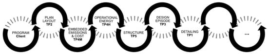
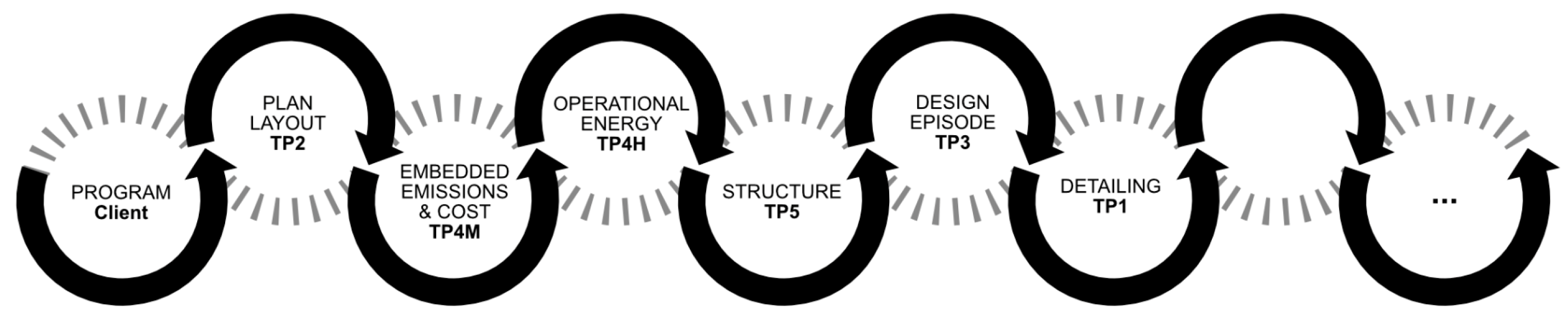
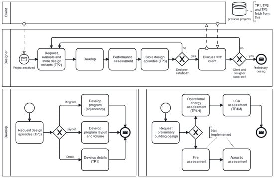
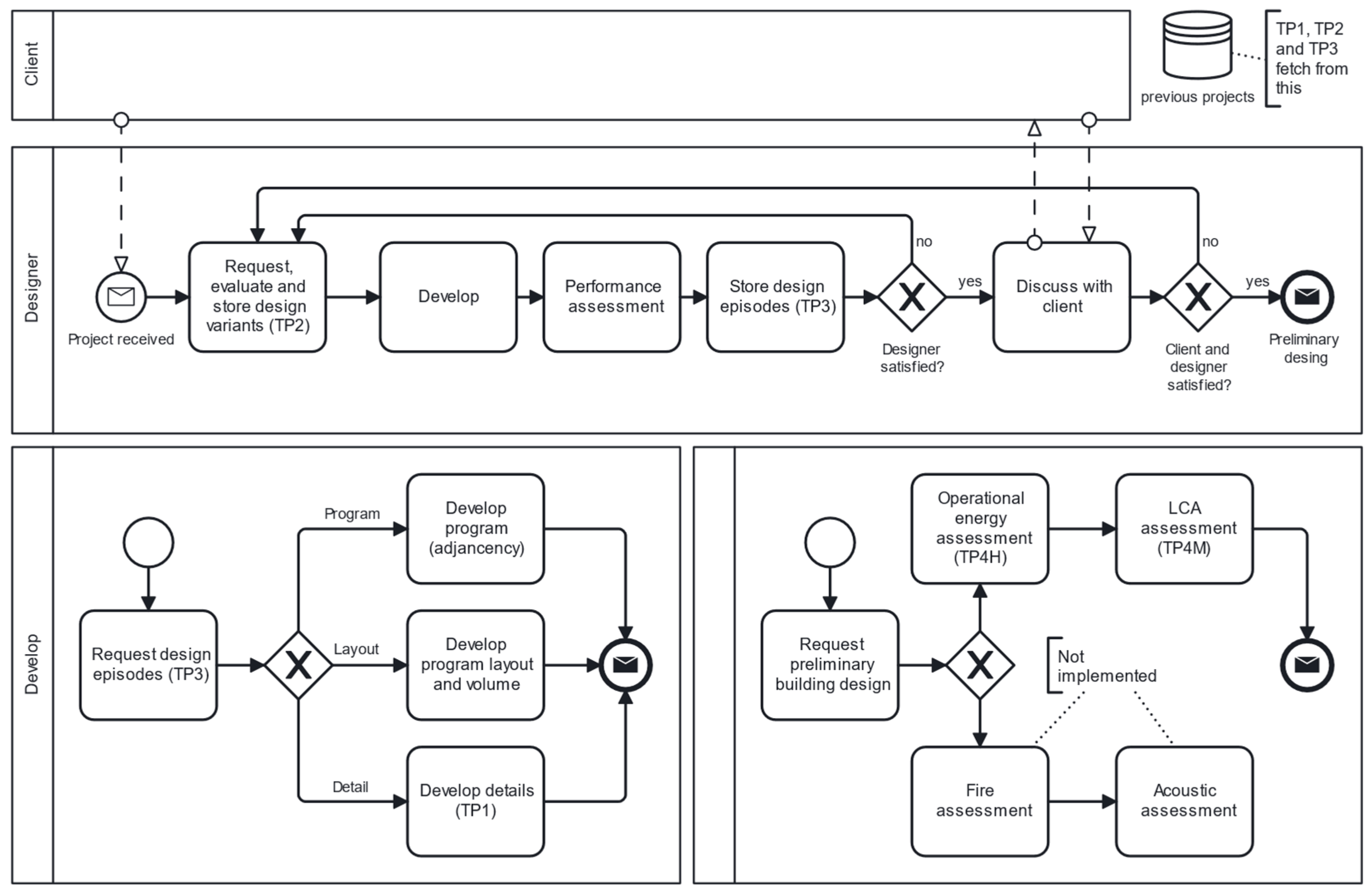
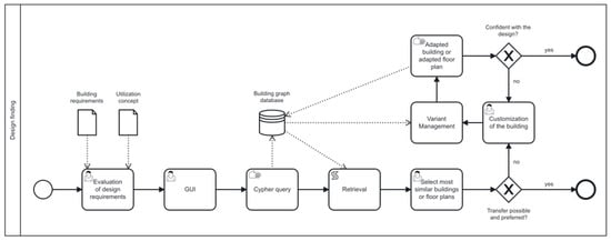
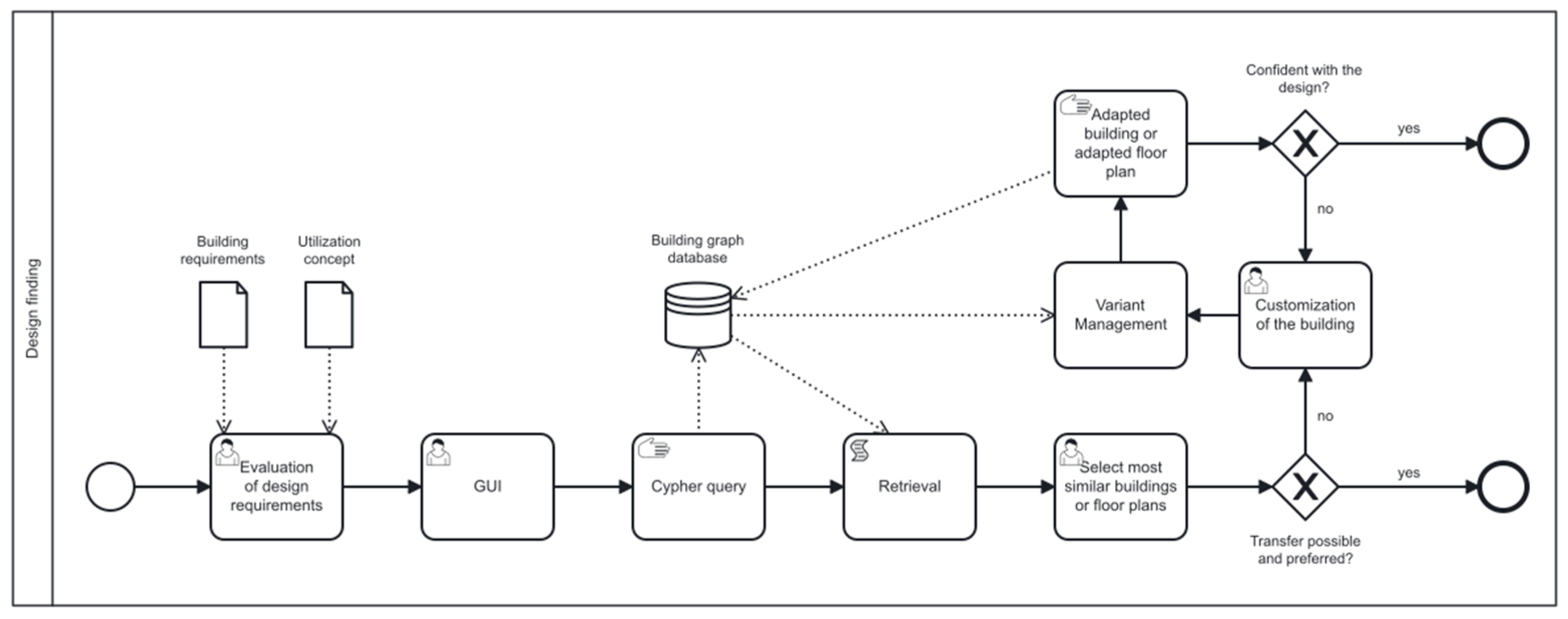
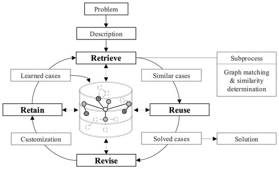
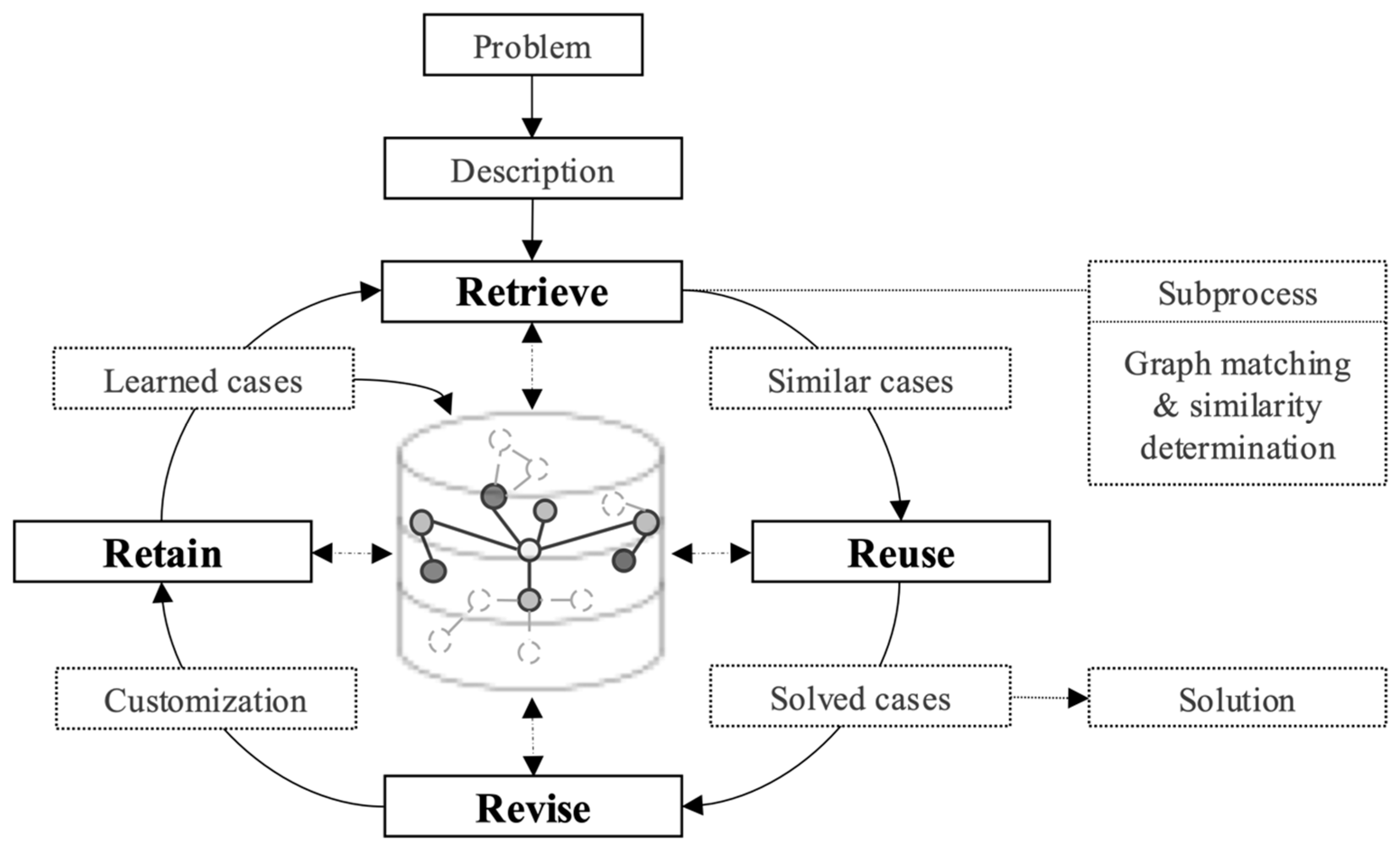
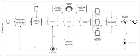
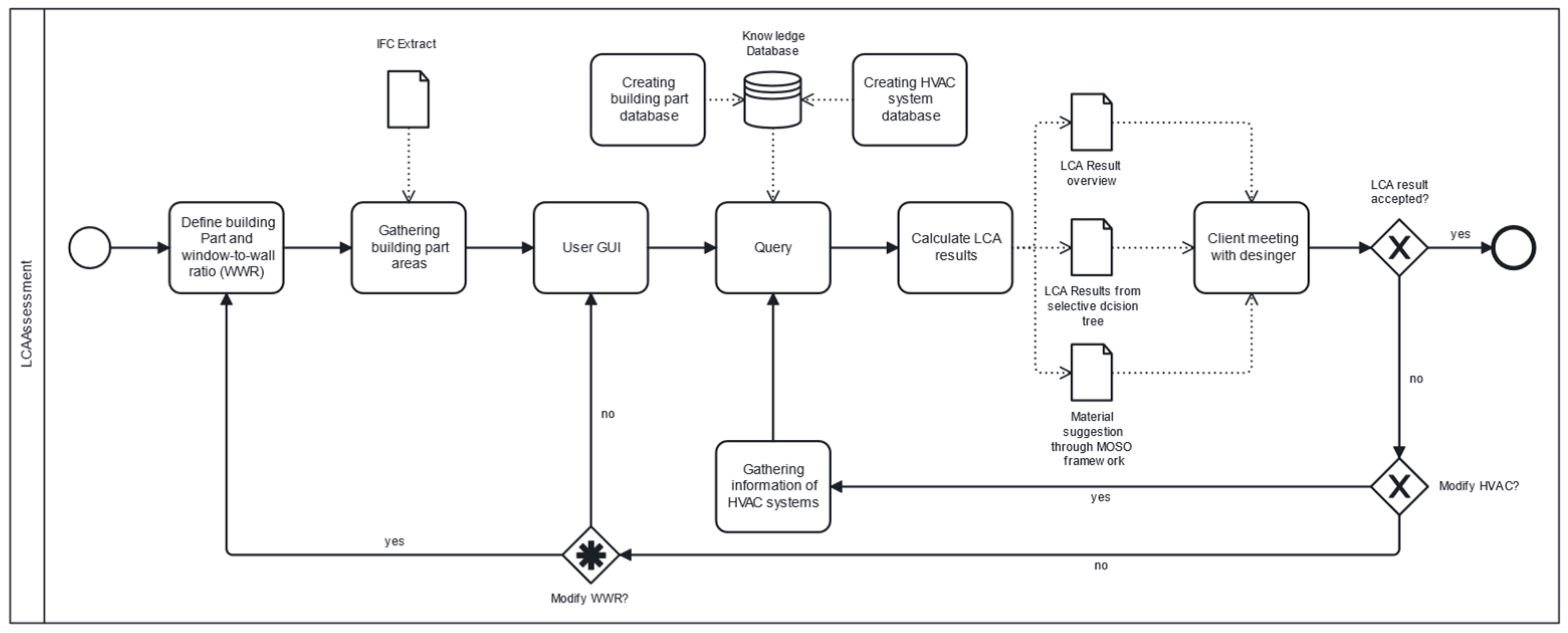
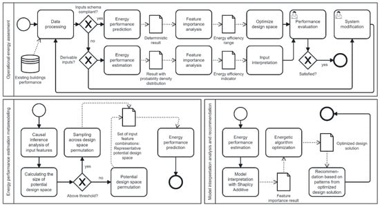
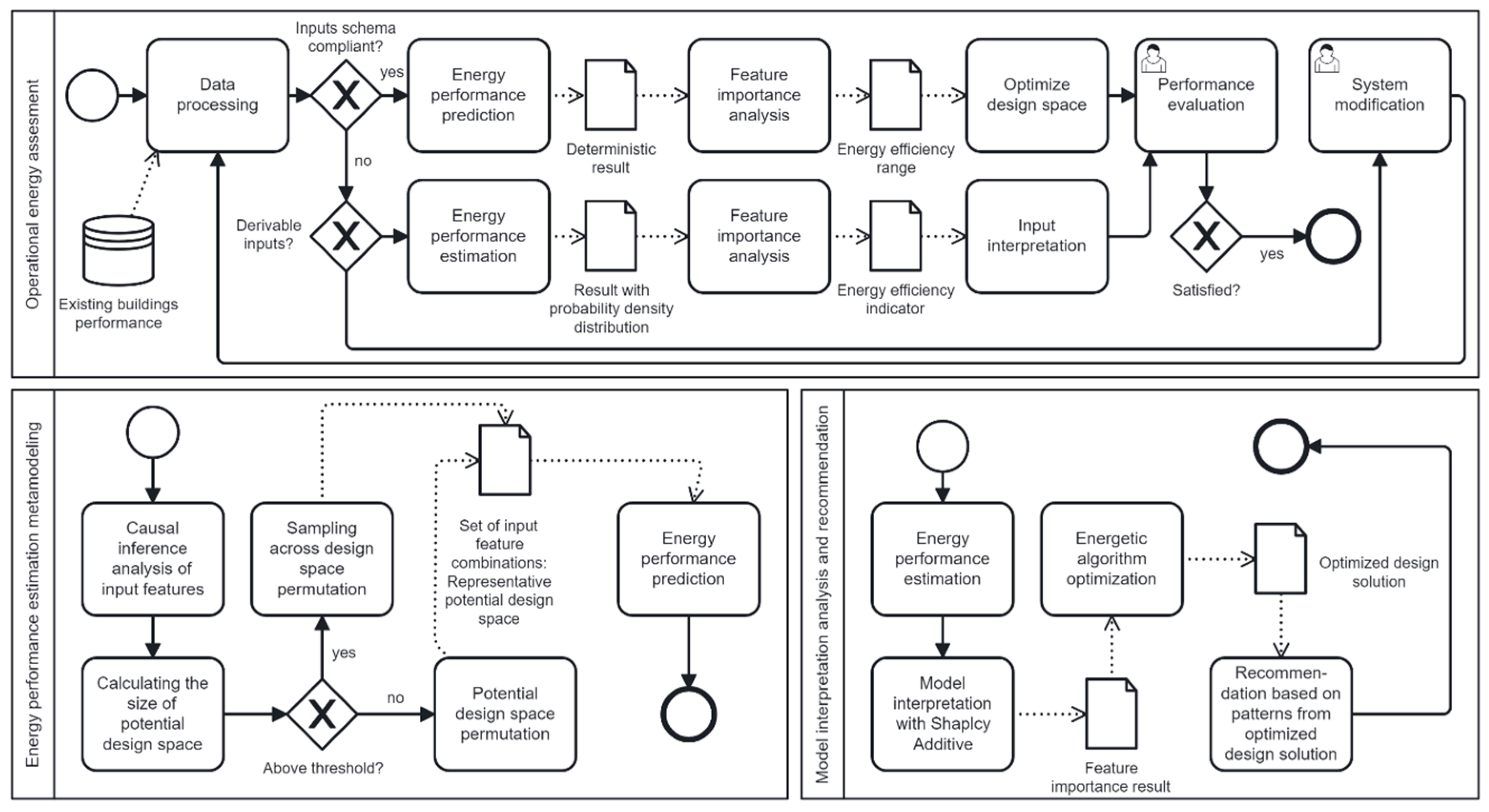
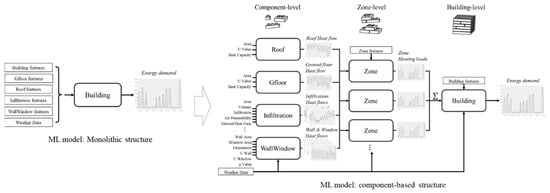
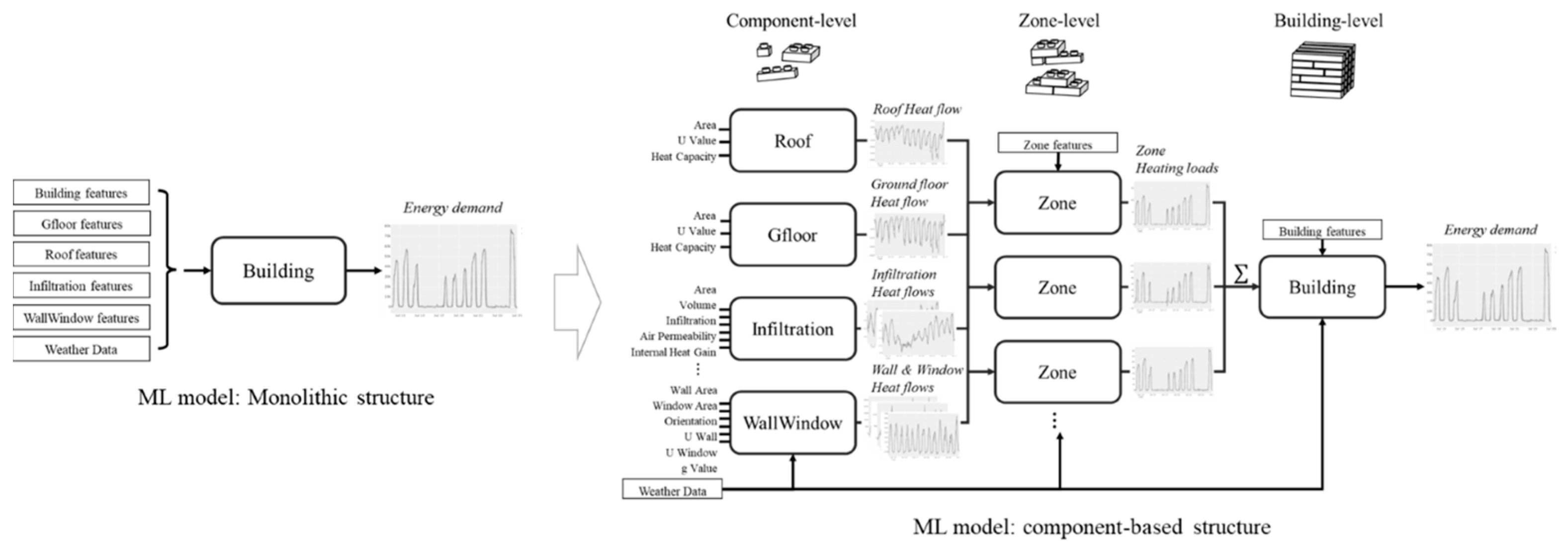
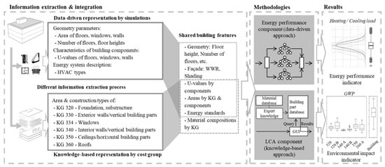
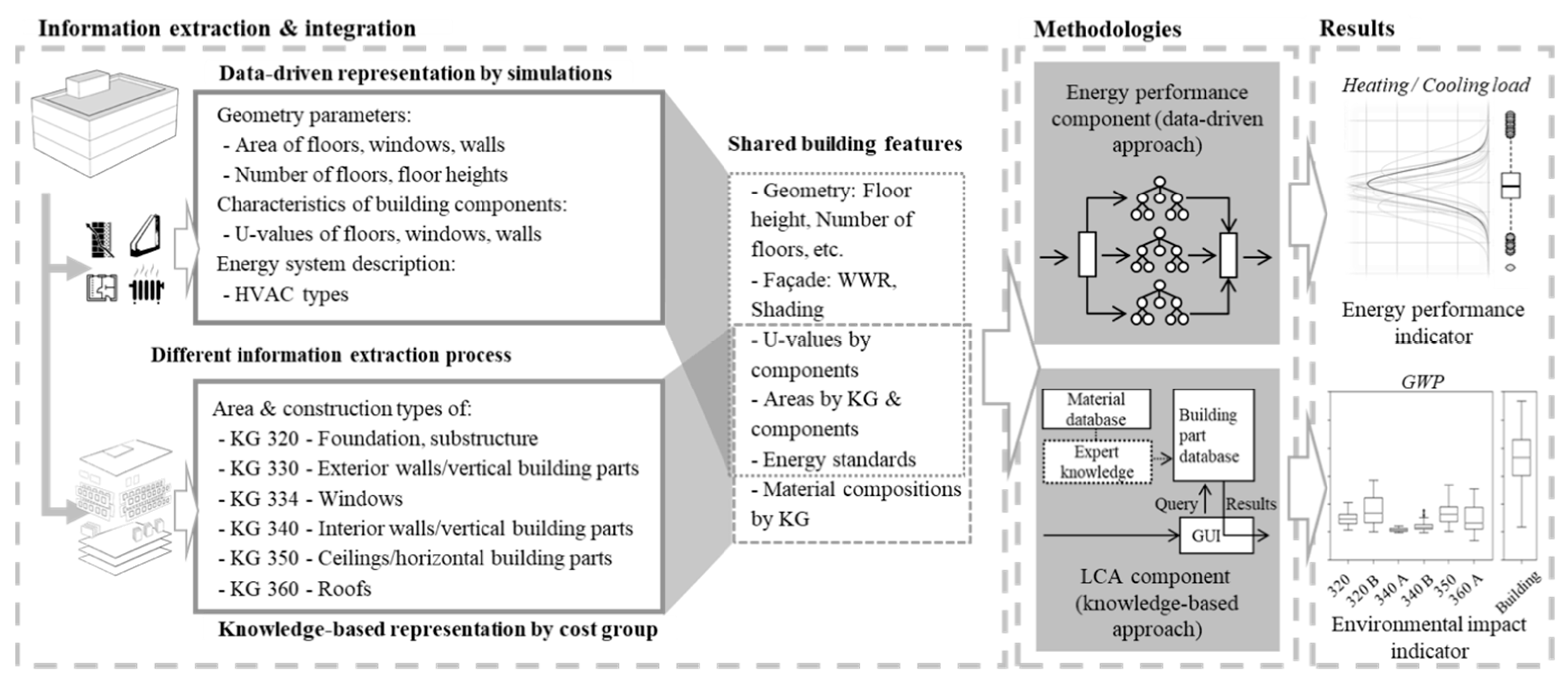
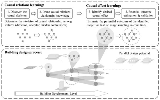
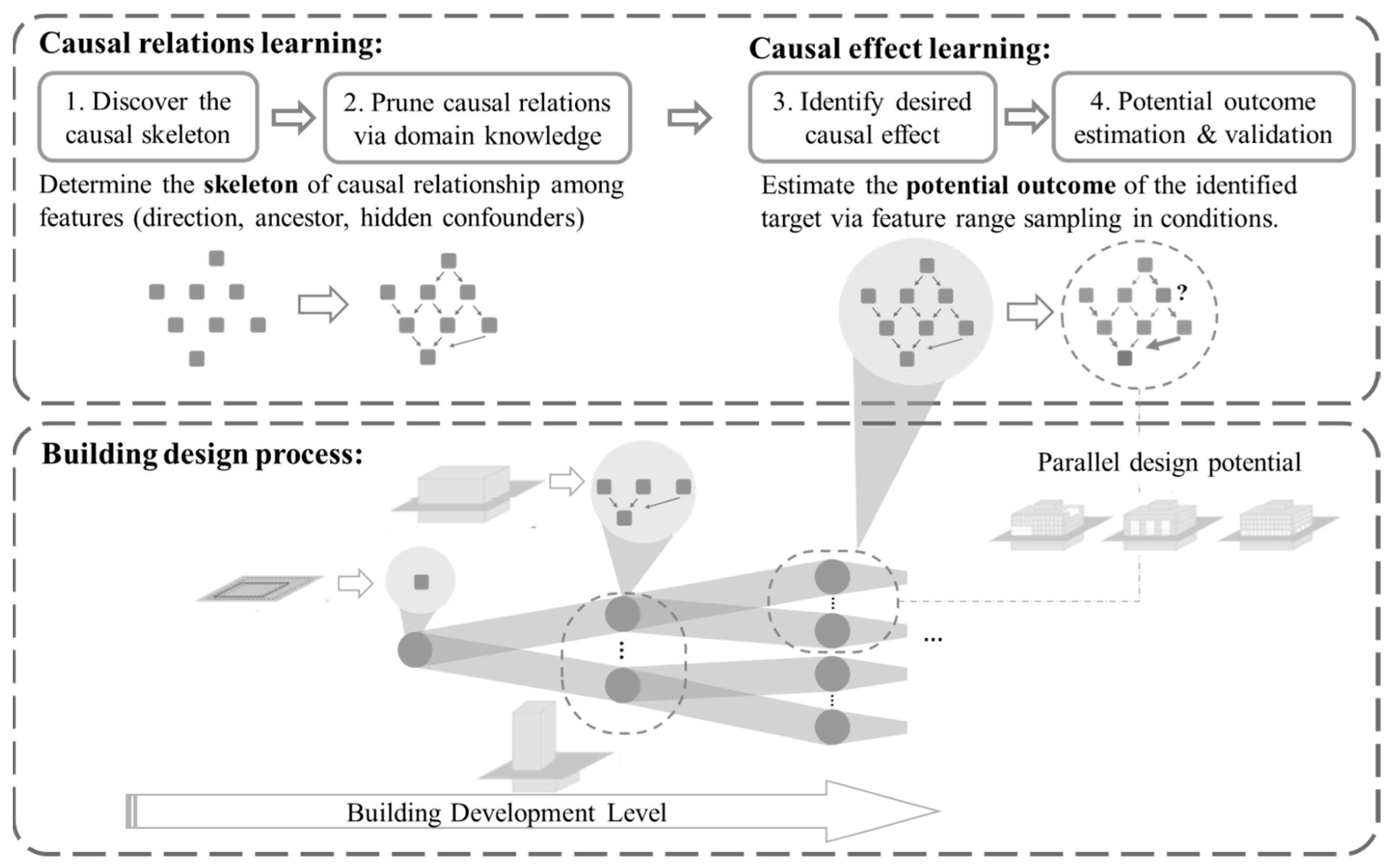
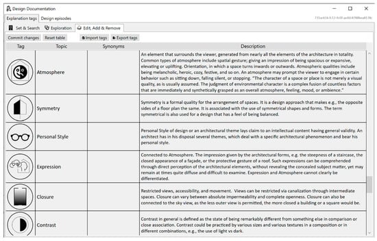
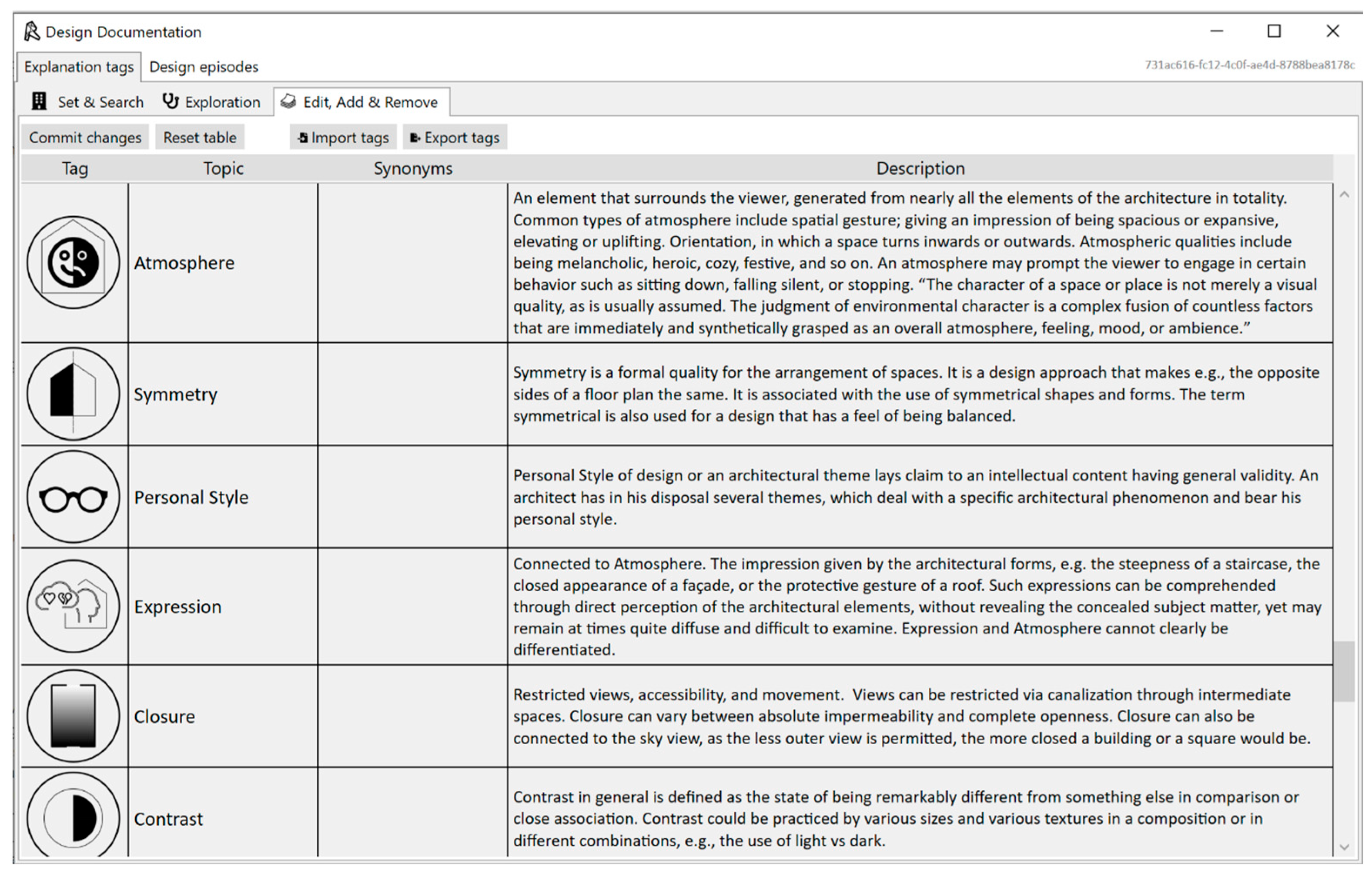
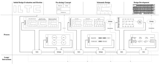
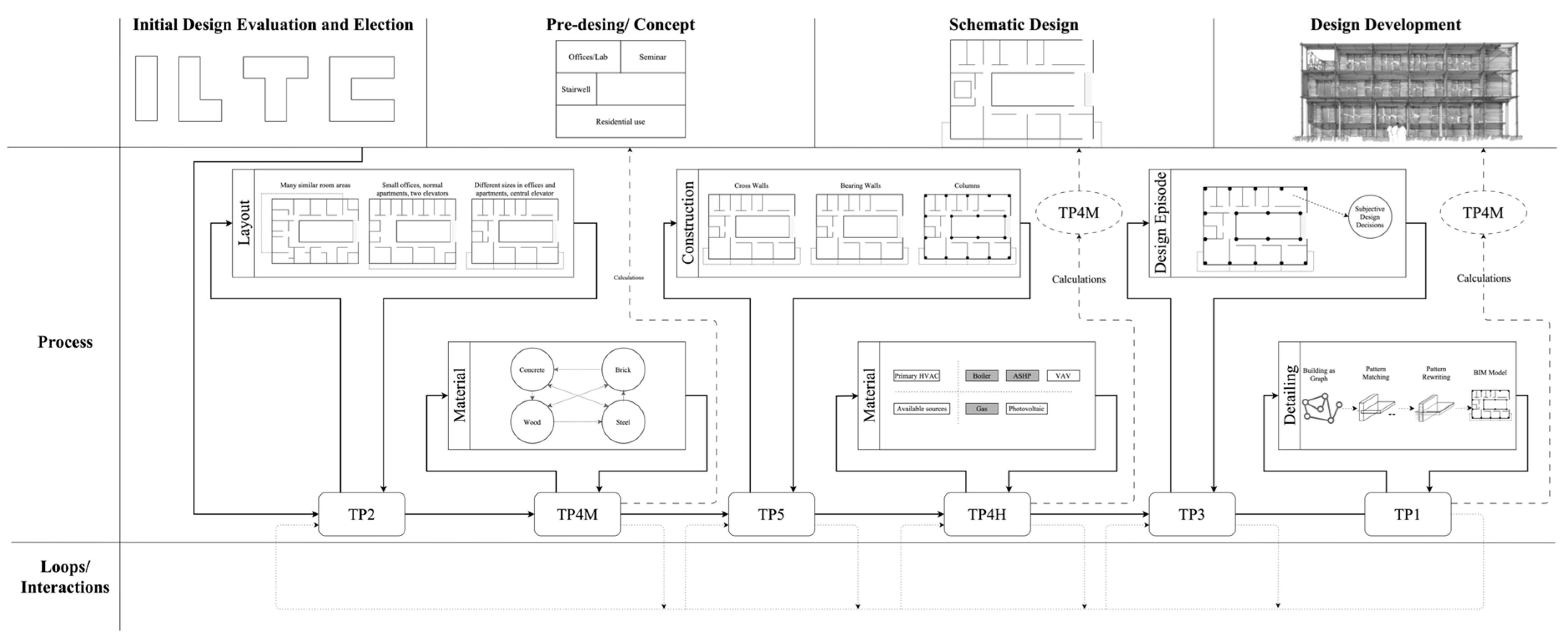
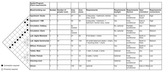
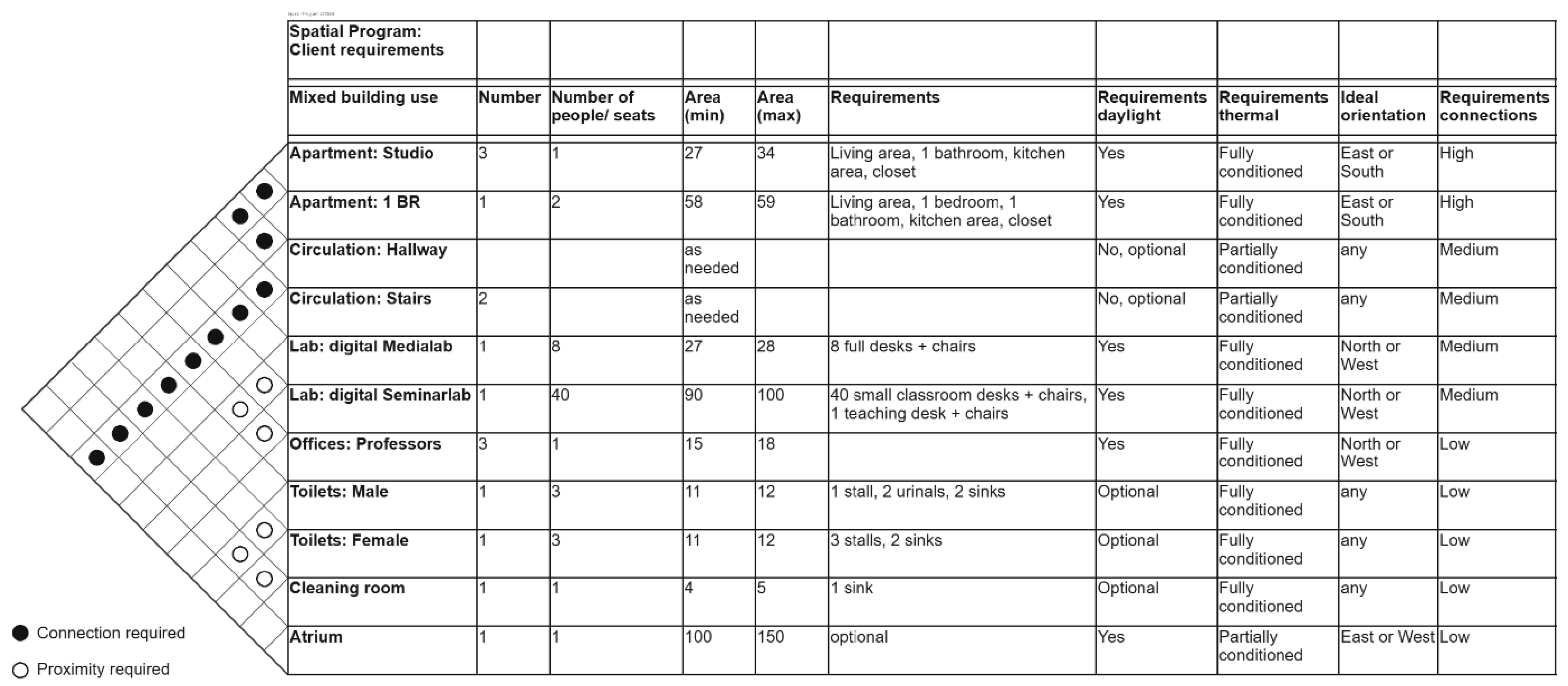
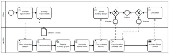
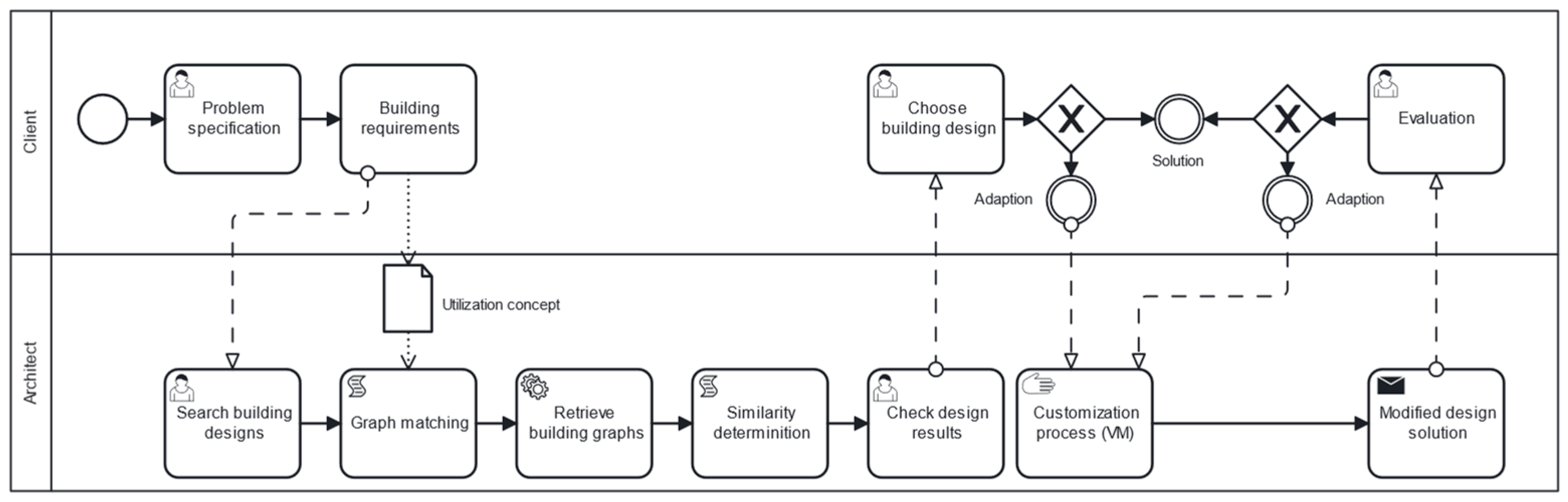
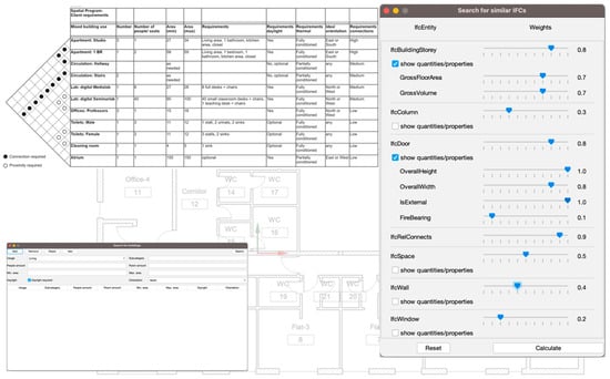
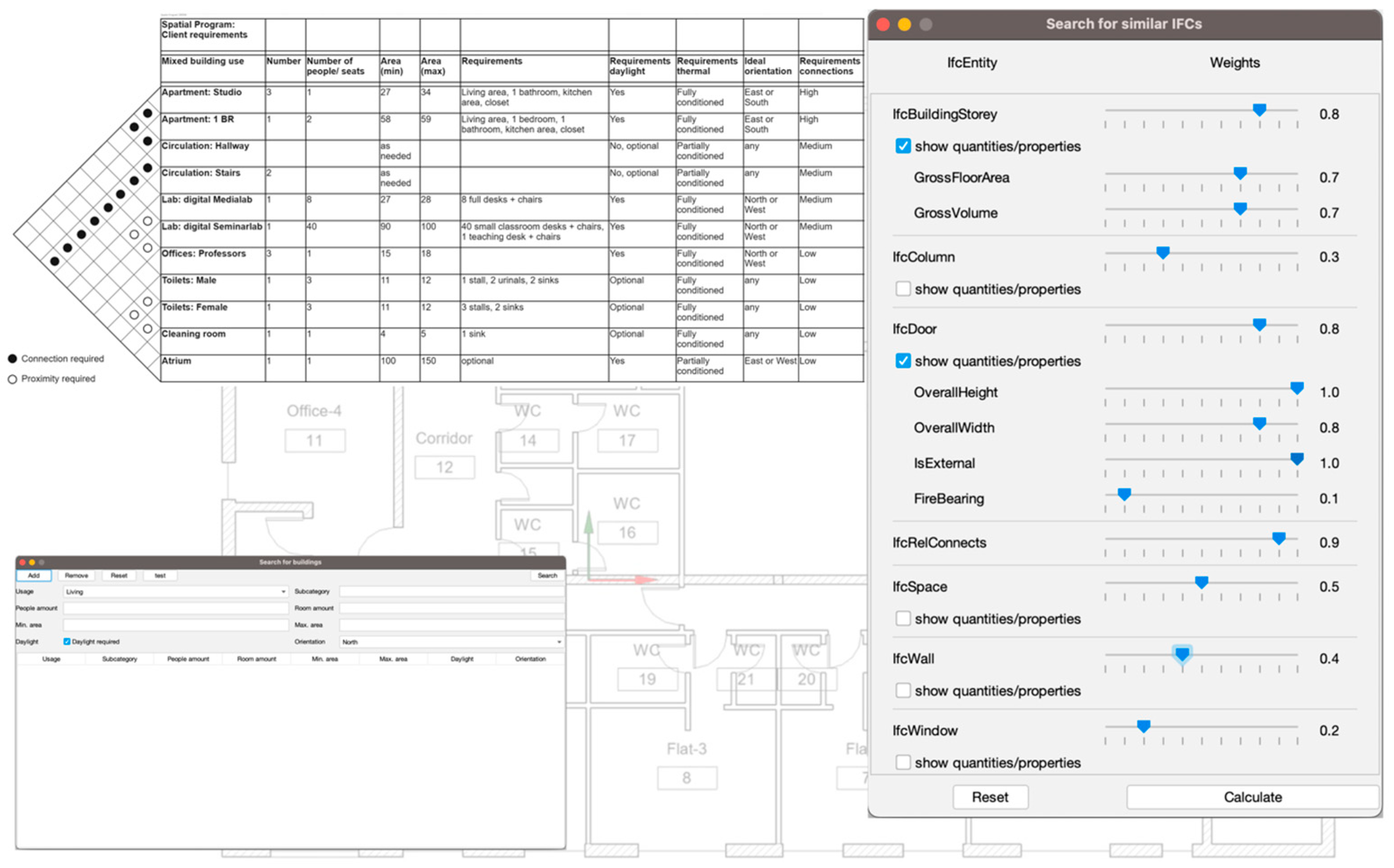
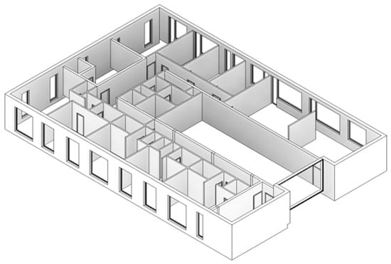
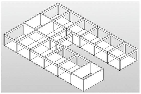
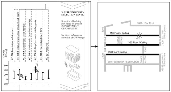
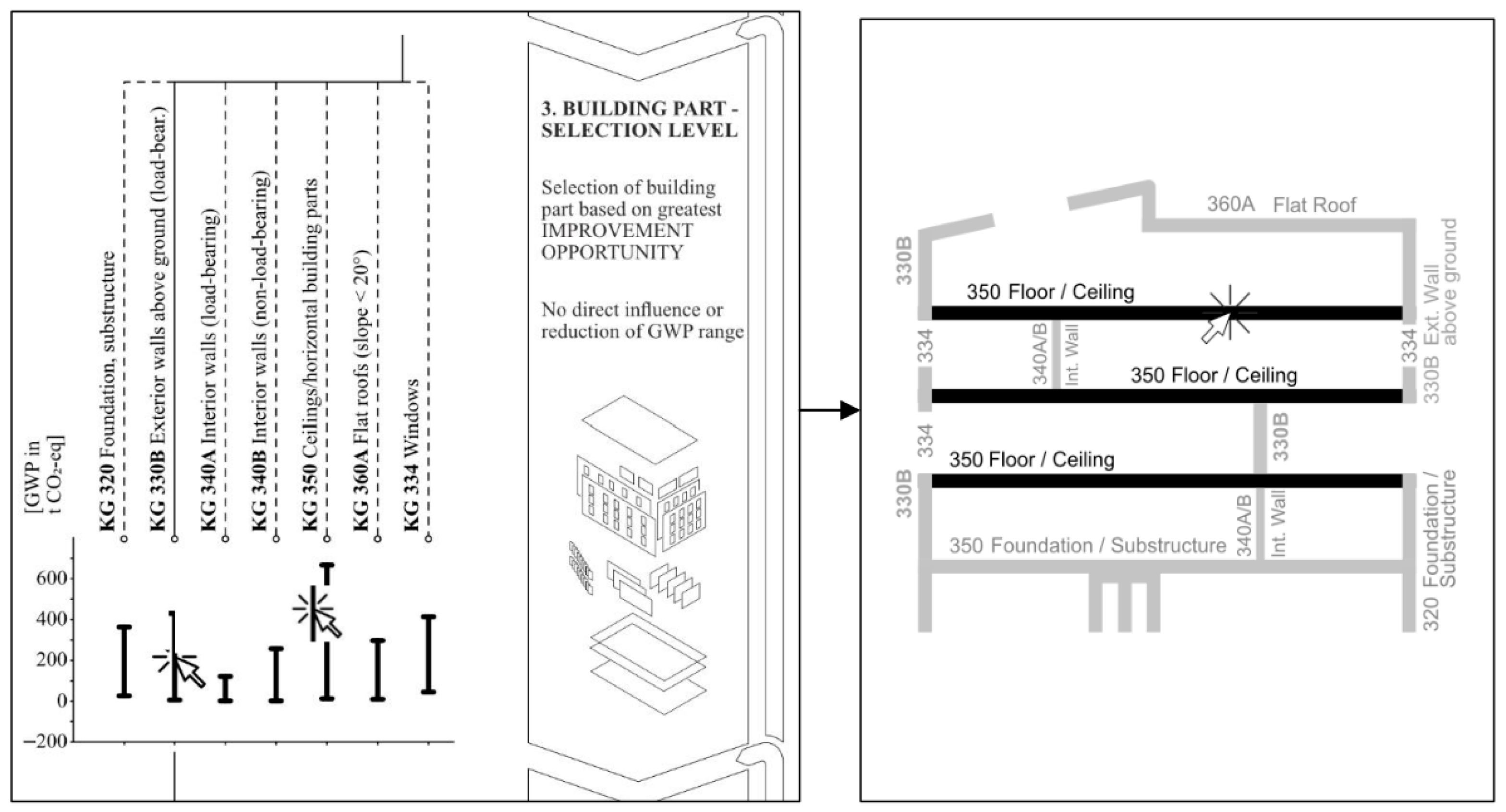
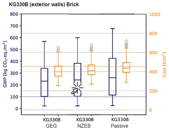
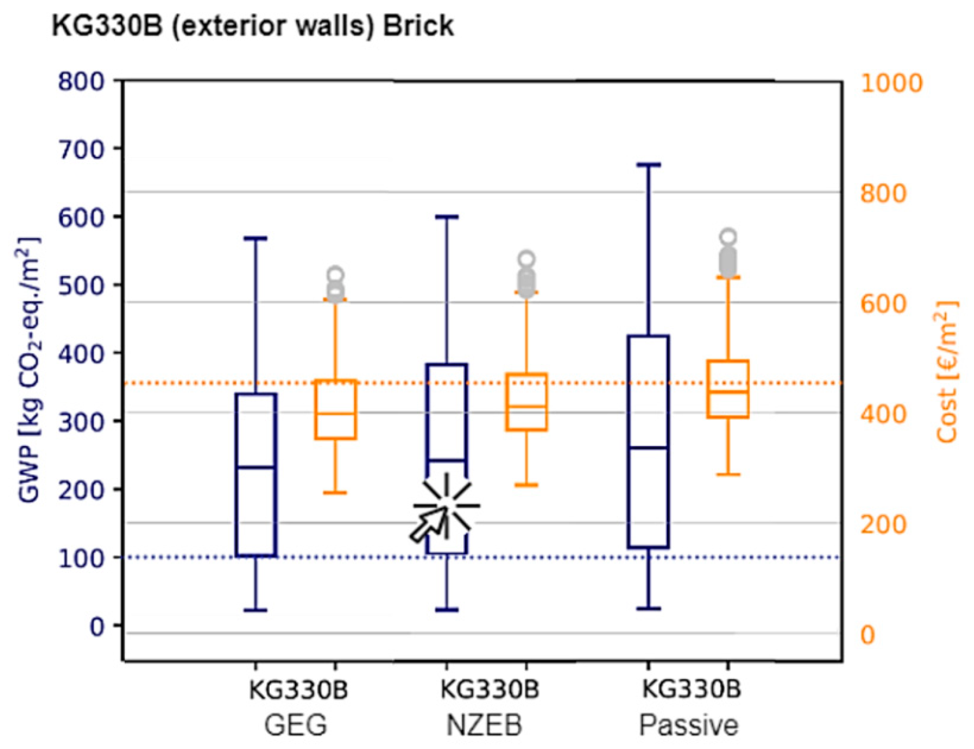
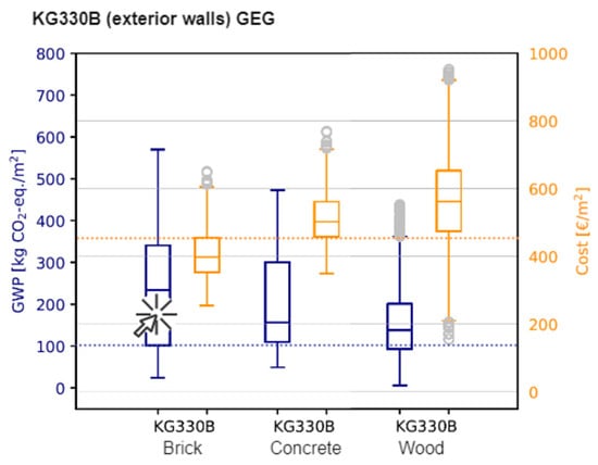
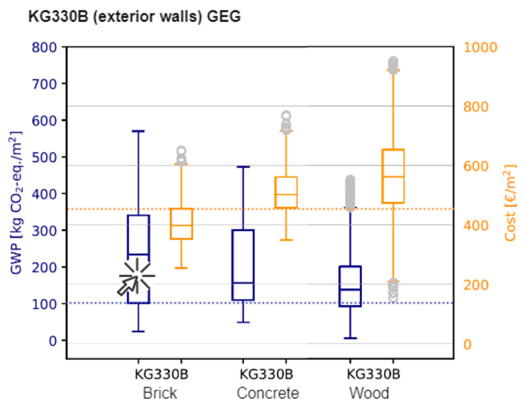
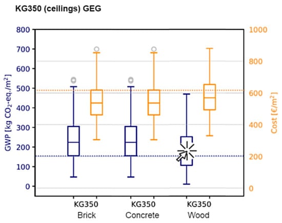
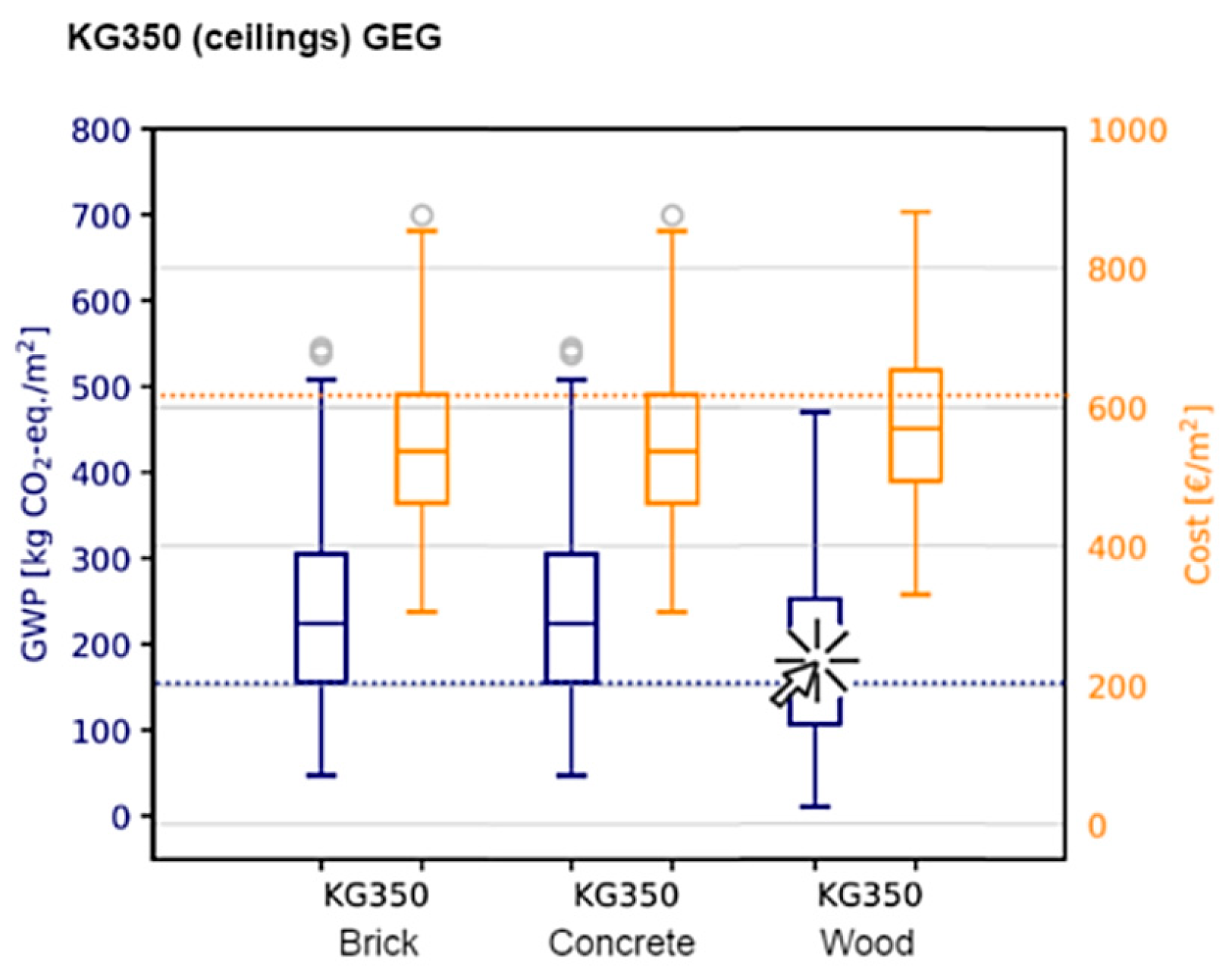
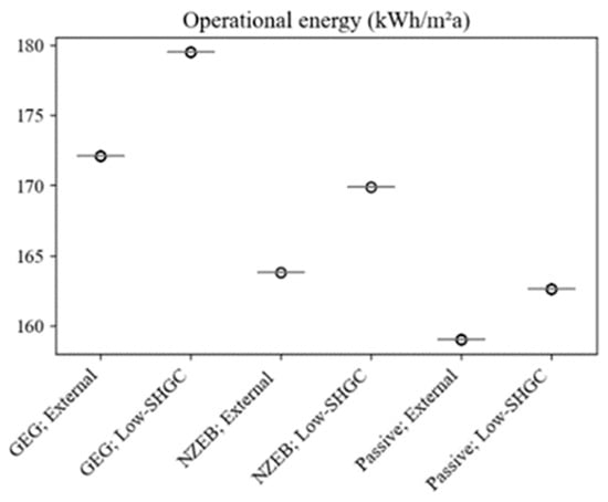
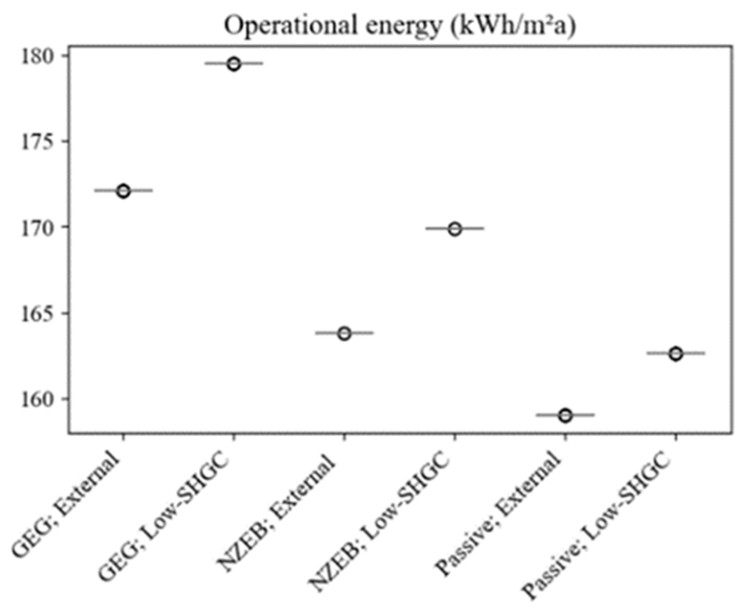
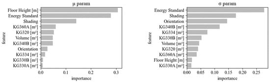
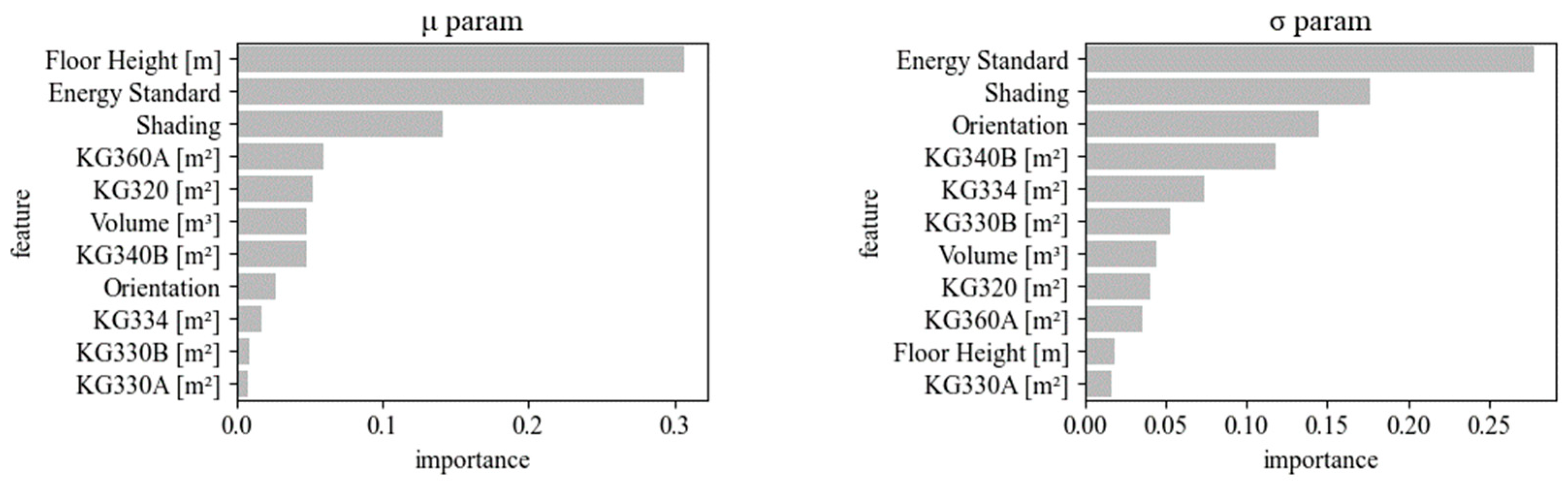
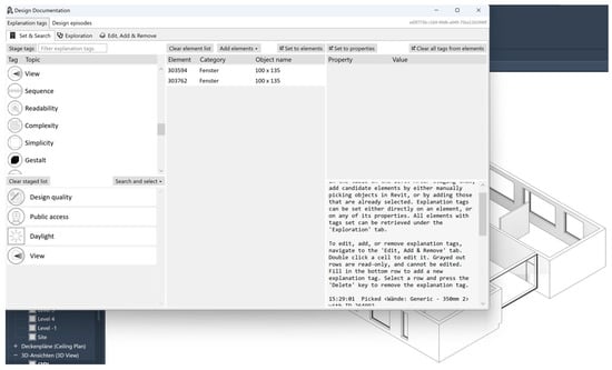
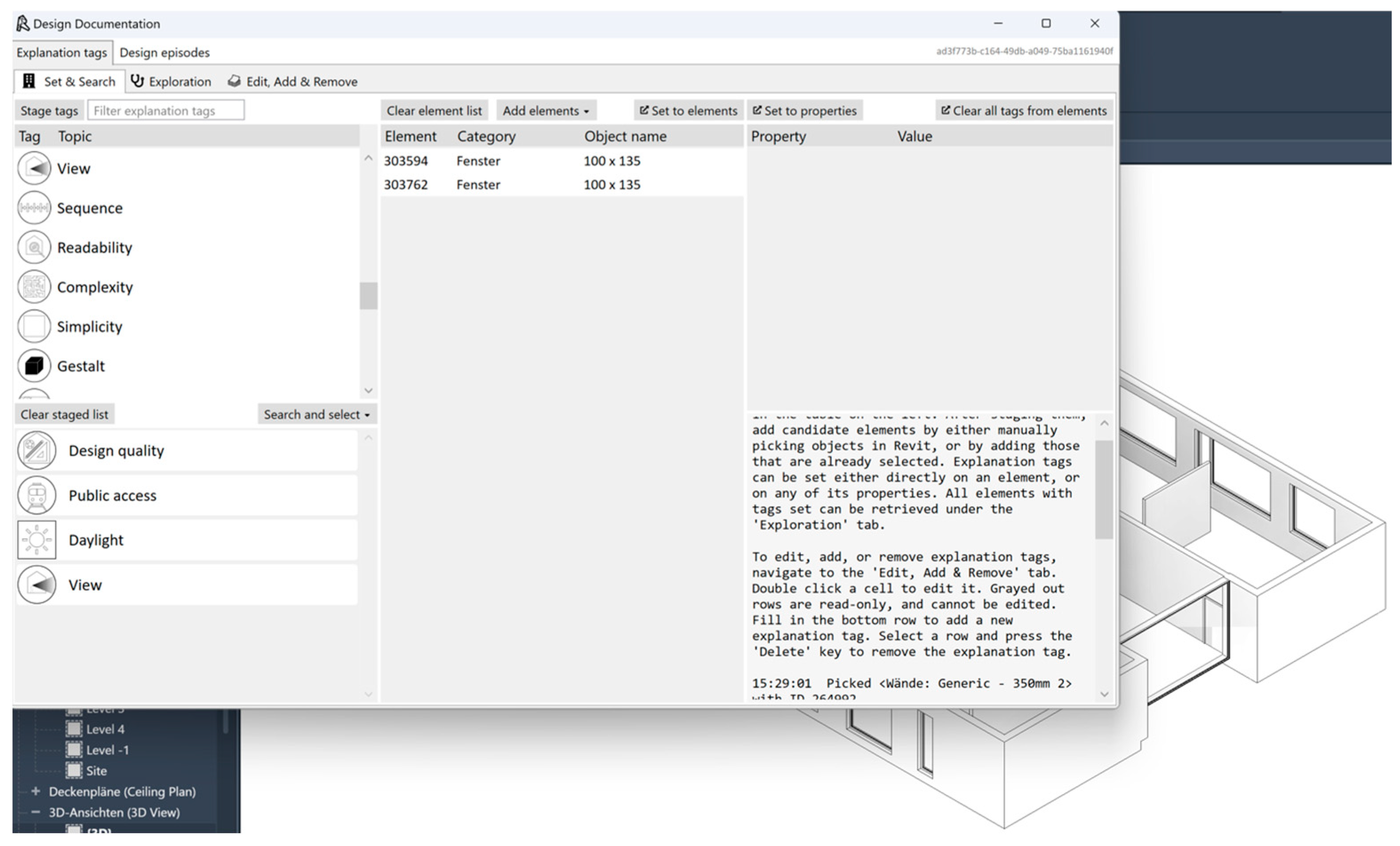

Disclaimer/Publisher’s Note: The statements, opinions and data contained in all publications are solely those of the individual author(s) and contributor(s) and not of MDPI and/or the editor(s). MDPI and/or the editor(s) disclaim responsibility for any injury to people or property resulting from any ideas, methods, instructions or products referred to in the content. |
© 2026 by the authors. Licensee MDPI, Basel, Switzerland. This article is an open access article distributed under the terms and conditions of the Creative Commons Attribution (CC BY) license.