


Abstract
This study presents an experimental and numerical investigation of reinforced concrete beams incorporating micro polypropylene, macro polypropylene, and steel fibers. Three concrete series of equal strength classes were prepared and tested to evaluate compressive strength, splitting tensile strength, flexural performance, and deformation behavior under short-term loading. Strain development in both concrete and reinforcement was measured using strain gauges and mechanical deformometers. In parallel with the experimental program, a nonlinear finite element model was developed using the DIANA FEAsoftware 10.5 to simulate the deformation behavior and strain development of the tested beams. The concrete material was represented using a total strain-based smeared crack model with rotating crack orientation, while the contribution of fiber reinforcement was incorporated through a CMOD-based post-cracking tensile constitutive law. The numerical results showed good agreement with the experimental load–deflection and strain measurements, confirming the suitability of the adopted modeling approach. These findings demonstrate that the combined experimental–numerical framework provides a reliable tool for assessing the deformation and cracking behavior of fiber-reinforced concrete beams. The experimental results indicate that fiber type and combination strongly influence the deformation behavior and mechanical performance of reinforced concrete beams, with hybrid systems incorporating steel fibers exhibiting enhanced flexural response, improved strain compatibility, and more ductile behavior compared to polypropylene-only reinforcement. The inclusion of steel fibers led to distributed cracking, delayed stiffness degradation, increases of up to approximately 6.3% in concrete strains and 10.3% in reinforcement strains, and a substantial improvement in compressive strength (up to approximately 28.8%), confirming the synergistic effect of hybrid fiber reinforcement.
1. Introduction
Concrete remains one of the most widely used construction materials due to its excellent compressive strength, ease of production, and cost-effectiveness. However, its brittle nature and inherently low tensile strength make it highly susceptible to cracking, particularly during early-age curing and under tensile and flexural stresses [1]. These cracks can compromise durability and long-term performance, especially in structural applications exposed to cyclic or sustained loading.
To mitigate these weaknesses, the incorporation of discrete fibers into the cementitious matrix has emerged as a reliable and increasingly adopted solution. Fiber-reinforced concrete (FRC) introduces fibers that act as crack arresters, bridging microcracks and inhibiting their propagation under both early and long-term loading conditions [2]. Depending on fiber type, geometry, and volume fraction, significant enhancements can be achieved in tensile strength, flexural capacity, toughness, and post-cracking behavior [3].
Recent studies have categorized fibers based on their dimensions and mechanical performance into macrofibers, microfibers, and high-strength steel fibers, each offering unique advantages. Macrofibers are primarily used to control crack widths and improve load-bearing capacity, while microfibers are more effective in reducing plastic shrinkage and thermal cracking [4]. Steel fibers, with their high modulus and tensile strength, have shown superior performance in improving flexural behavior and energy absorption under dynamic or impact loading [5,6].
The effectiveness of fiber reinforcement is not limited to mechanical behavior; it also impacts the rheological properties of fresh concrete. Wang [5] provided a comprehensive review of how different fibers affect flowability, viscosity, and workability, noting that rheological behavior plays a key role in achieving homogeneous fiber dispersion and effective load transfer.
Najaf and Abbasi [7] experimentally demonstrated that polypropylene fibers significantly improved both compressive and flexural strength, with fibrillated polypropylene achieving a 58% gain in flexural strength at 1.5% fiber content. Agrawal and Chandak [8] further highlighted the role of hybrid fiber systems in self-compacting concrete, using Taguchi design methods to show how the interaction between steel and polymer fibers enhances mechanical and durability parameters.
In terms of testing methodologies, the RILEM TC 162-TDF [9] standard is widely recognized for evaluating the flexural performance of FRC, especially in relation to crack development and post-cracking behavior under three-point bending conditions. Complementary assessments using cube and cylinder specimens help establish a more comprehensive view of strength development, modulus of elasticity, and crack initiation thresholds [10].
Aidarov et al. [11] report three-point bending tests on notched MSFRC (macro-synthetic fiber-reinforced concrete) beams (100 × 100 × 400 mm prisms) containing 30–40 mm polypropylene macrofibers at 4 kg/m3 and 8 kg/m3, tested at temperatures from +20 °C down to −30 °C, with continuous load–CMOD curves obtained to determine first-crack and residual strengths at service (0.5 mm CMOD) and ultimate (2.5 mm CMOD) opening levels. The outcome of the described research program reveals the enhanced performance of the given FRCs in terms of pre- and post-cracking flexural strengths; therefore, these phenomena should be taken into account during the design procedures of elements that are to be subjected to low temperatures during transient or in-service conditions.
Suárez et al. [12] present calibrated numerical and experimental flexural testing of macro polyolefin FRC beams under varying temperatures. They have studied how high temperature exposure affects the parameters of a trilinear softening diagram that allows for numerically reproducing the behavior of PFRC specimens through a cohesive model. To do this, the experimental results of [13] have been used as reference and an embedded cohesive crack fracture model was employed, with the softening behavior defined by a trilinear diagram.
Enfedaque et al. [14] simulate fracture behavior of high-performance FRC via cohesive crack inverse analysis. Their study implemented multi-linear softening functions in a user material subroutine of a finite element code (ABAQUS) in order to simulate the three-point bending fracture behavior of three SFRC (steel fiber-reinforced concrete) and two FRC with cocktails of fibers. The results obtained showed that the methodology used is a robust and efficient approach to simulate the fracture behavior of the concrete mixes analyzed.
Lamus et al. [15] demonstrate a validated numerical model for SFRC flexural beams. They present experimental three-point bending of notched prisms (150 mm thick) with 50–60 mm steel fibers at 1–2% vol, yielding full load–deflection curves, and calibrate/validate a nonlinear FEM (CSD approach) against these curves.
Enfedaque et al. [16] investigate the fracture behavior of concrete beams reinforced with polyolefin macrofibers through three-point bending tests on notched prisms using 60 mm fibers. They calibrate trilinear σ–w cohesive crack laws in Abaqus to replicate the full experimental load–deflection curves. The study provides detailed experimental load–deflection data, performs inverse identification of the constitutive law, and successfully validates the numerical simulations for macrofiber-reinforced concrete, fulfilling all key evaluation criteria.
Suárez et al. [17] present a predictive numerical study on the flexural behavior of macrofiber-reinforced concrete beams. Their work involves full load–deflection curves obtained from experimental three-point bending tests on PFRC specimens reinforced with 48 mm polyolefin macrofibers. A finite element cohesive model incorporating a trilinear softening law is calibrated and validated using this experimental data. The study provides original flexural test results following [18] and achieves close agreement between experimental and size-dependent numerical simulations, accurately capturing both load–deflection response and residual strength behavior.
Albayyati et al. [19] examine the flexural performance of steel fiber-reinforced concrete (SFRC) beams using both experimental testing and finite element modeling. They conduct three-point bending tests on notched beams reinforced with steel macrofibers, recording full load–CMOD (crack mouth opening displacement) curves. A two-dimensional nonlinear finite element model based on a cohesive crack approach is calibrated to the experimental data. The study provides both the experimental beam test results and validated numerical simulations, demonstrating strong agreement between the two.
Sucharda et al. [20] present a study focused on identifying the mechanical and fracture properties of self-compacting concrete beams for use in nonlinear finite element analysis. They outline a comprehensive procedure for determining these properties based on an extensive series of tests conducted on notched beams.
Sorelli et al. [21] investigate the flexural and tensile behavior of hybrid steel fiber-reinforced concrete incorporating both micro and macrofibers. They conduct experimental bending tests, reporting toughness and size effects, and perform numerical fracture mechanics simulations to assess the contributions of each fiber type. The study includes macro steel fibers alongside microfibers, provides experimental load–deflection data, and establishes a connection between experimental results and numerical modeling. However, the hybrid fiber composition may influence the ability to isolate the specific effects of macrofibers.
Enfedaque et al. [22] evaluate the effectiveness of multi-linear softening laws in modeling the fracture behavior of fiber-reinforced concrete (FRC) beams. They perform three-point bending tests on beams reinforced with 60 mm polyolefin, steel, and glass fibers, and apply finite element inverse analysis to match the resulting load–deflection curves. The study provides complete experimental load–deflection data and calibrates numerical models accordingly, achieving strong validation and directly meeting the key requirements for macrofiber FRC beam flexure analysis.
Yeo et al. [23] evaluate the applicability of MC2010 tensile constitutive model for SFRC beams, conduct three-point bending tests on notched beams and calibrate FE simulations against experimental load–displacement curves without bar reinforcement, present original beam flexural tests (macro steel fibers), full load–displacement curves, and direct numerical modeling/calibration; notes orientation factor is critical for post-peak accuracy.
Kachouh et al. [24] develop and calibrate a bilinear tensile softening law for steel fiber-reinforced concrete through inverse analysis of experimental four-point bending tests on 100 × 100 × 500 mm prisms, following ASTM C1609. Full load–deflection curves are used to derive the softening behavior, which is then applied to finite element models of large-scale deep beams for validation.
Meškėnas et al. [25] conduct an experimental and numerical investigation of the flexural behavior of steel fiber-reinforced concrete (SFRC) beams. They perform three-point bending tests on notched beams containing 0.5% and 1.0% steel fibers and use the resulting load–deflection data to calibrate an inverse stress–strain (σ–ε) or stress–crack width (σ–w) relationship. The calibrated model is then validated through nonlinear finite element simulations, demonstrating strong agreement with the experimental results.
Unuk et al. [26] compared the experimental and numerical load–displacement responses of polymer macrofiber-reinforced concrete beams. Three-point bending tests were conducted on notched prisms, and semi-analytical and finite element models were calibrated to accurately reproduce the measured load–deflection and CMOD responses. The tensile constitutive properties were identified through inverse analysis of the experimental data, with the reinforcement consisting of macro-scale polymer fibers.
Gao et al. [27] examine the flexural behavior of steel fiber-reinforced concrete beams incorporating conventional steel reinforcement. They perform experimental bending tests and apply inverse analysis based on load–CMOD (crack mouth opening displacement) data to model the tensile response. The specimens contain 1.0% volume of steel fibers (length unspecified) alongside steel rebars. While the numerical model is calibrated to match experimental results, the presence of rebar complicates the isolation of the fibers’ individual contribution to the overall behavior.
Abdel-Karim et al. [28] tested fourteen half-scale RC beams under four-point bending and showed that combining innovative steel–GFRP hybrid bars with up to 2% hybrid structural polypropylene fibers significantly increased peak flexural strength, bending stiffness and ductility, and enabled large inelastic deformations comparable to conventional steel-RC beams, with fibers markedly improving the post-peak response through crack-bridging. They also proposed an ACI-544-based expression for the nominal flexural capacity of hybrid-fiber beams with hybrid bars, which matched their tests and 44 additional specimens from the literature with a standard deviation of about 0.12, and confirmed the experimental behavior with 3D nonlinear finite-element simulations.
Esquivel et al. [29] investigated RC beams with minimum-level longitudinal reinforcement (ρl ≈ 0.3%) and showed that adding 1% steel or polypropylene fibers can increase yield load by up to 50% and maximum load by about 25%, while markedly enhancing post-cracking stiffness. Their results further indicate that, in low-ρl beams, high-stiffness steel fibers promote crack localization and can reduce ductility by more than 60% in short spans, whereas polypropylene fibers lead to more distributed cracking and only a modest ductility reduction, despite similar gains in stiffness and capacity.
Pouraminian et al. [30] developed a multiscale finite element model to study the pull-out behavior of ribbed steel bars embedded in CNT-modified ultra-high-performance fiber-reinforced concrete incorporating recycled steel fibers from waste tires. Their results showed that nano-modification of the matrix combined with recycled steel fibers significantly enhances bond strength and post-cracking energy absorption, and that the proposed numerical framework can accurately reproduce experimental load–slip responses. This highlights the critical role of fiber-reinforced matrices and reliable numerical bond modeling in predicting the structural response of reinforced concrete members.
Abadel et al. [31] demonstrated the flexural performance of hybrid-fiber reinforced concrete beams with steel–GFRP hybrid longitudinal rebars through tests on four simply supported beams (120 × 185 × 1500 mm) under two-point loading. The beams contained 1% hybrid fibers (0.75% hooked steel + 0.25% polypropylene), and the tensile reinforcement combined steel and GFRP bars; load–deflection response, cracking behavior, and ultimate load were recorded. The results showed that hybrid fibers reduced crack width and propagation compared with normal concrete; the peak loads of fiber-reinforced beams increased by up to 13.2%, and replacing steel bars with GFRP bars increased load capacity by up to 42.5%, providing direct experimental evidence of enhanced bending capacity, crack control, and the benefits of hybrid reinforcement systems.
The study by Vadivel et al. [32] experimentally investigated the mechanical and microstructural behavior of hybrid fiber-reinforced concrete (HFRC) incorporating steel, glass, and polypropylene fibers. The optimal HFRC mixtures showed significant enhancement in mechanical performance compared with plain concrete: compressive strength increased by approximately 20–25%, split tensile strength by about 30%, and flexural strength by up to 35%. Additionally, the modulus of elasticity improved by 15–20%, contributing to better stiffness and load-bearing capacity. Scanning electron microscopy revealed that fiber inclusion densified the concrete matrix and strengthened the interfacial transition zones, effectively mitigating micro- and macro-crack propagation.
Medeghini et al. [33] provided a comprehensive critical review of fiber orientation and orientation factors in steel fiber-reinforced concrete beams with hybrid fibers. The authors emphasized that fiber orientation has a decisive influence on post-cracking behavior, load-carrying capacity, and toughness, and that current design-code orientation factors are often based on limited experimental evidence. The review compared available experimental and analytical techniques for determining fiber orientation—such as electromagnetic induction, image analysis, and micro-CT—and highlighted the need for more accurate orientation models for hybrid fiber systems.
In recent years, nonlinear finite element modeling has become an essential tool for interpreting and extending experimental investigations of fiber-reinforced concrete elements. Advanced numerical frameworks allow for detailed assessment of cracking patterns, strain localization, and deformation mechanisms that are difficult to capture experimentally. In this context, finite element software such as DIANA has been widely applied to model reinforced concrete structures using smeared cracking formulations and fracture-based constitutive laws. When properly calibrated, such models provide valuable insight into the structural response of fiber-reinforced concrete beams and enable direct comparison with experimentally measured load–deflection and strain responses.
Despite the extensive research on fiber-reinforced concrete beams, several gaps remain. Many existing studies focus on either material scale properties or flexural strength without detailed strain measurements in both concrete and reinforcement. Moreover, the combined use of micro polypropylene, macro polypropylene, and steel fibers in conventionally reinforced concrete beams has received limited attention, particularly regarding deformation compatibility and crack development. Additionally, numerical investigations that explicitly validate strain-based experimental measurements using nonlinear finite element models remain scarce. The present study addresses these gaps by integrating detailed experimental strain measurements with validated numerical simulations.
This study builds upon the growing body of research by experimentally evaluating three series of concrete mixtures of equal strength class, each reinforced with a different fiber type—macrofibers, microfibers, and steel fibers. The research employs a variety of test specimens (cubic, cylindrical, prismatic) and structural elements (reinforced beams) to assess compressive strength, crack-induced tensile behavior, flexural strength via the RILEM method, and elastic modulus. Special emphasis is placed on comparing measured deformation behavior and crack development to theoretical predictions under both short-term and long-term loading.
Through this comprehensive approach, the paper aims to deepen understanding of how different fiber types influence the mechanical characteristics of FRC and to provide practical guidance for optimizing fiber selection in structural applications.
The main contribution of this study lies in the combined experimental and numerical investigation of reinforced concrete beams incorporating different configurations of polypropylene (micro and macro) and steel fibers. While previous studies have primarily focused on either material-level characterization or isolated flexural performance, the present work provides a comprehensive assessment of deformation behavior, strain development in concrete and reinforcement, and crack evolution under service and ultimate loading conditions. Furthermore, a nonlinear finite element model developed in DIANA is used to validate the experimental findings, offering additional insight into the mechanisms governing crack bridging and post-cracking stiffness in hybrid fiber-reinforced concrete beams.
2. Materials and Methods
2.1. Materials
The concrete mix design incorporated a combination of limestone in two fractions, 4–8 mm and 8–16 mm, along with river aggregate (0–4 mm) as the fine aggregate. The binder used was a blended Portland cement, type CEM II/A-M 42.5N, conforming to [34] The water-to-cement ratio (W/C) was maintained at 0.524 across all mixes to ensure consistency in workability and strength development. Three types of fibers were employed for reinforcement: macro polypropylene fibers, micro polypropylene fibers, and steel fibers. Each fiber type was used in a separate concrete series to evaluate its individual influence on the mechanical and rheological properties of the concrete.
In this study, three concrete series—B1, B2, and B3—were prepared, each incorporating different types and combinations of fiber reinforcement as additional materials:
- The B1 series was reinforced with macro polypropylene fibers at a dosage of 0.38% by volume, equivalent to 3.64 kg/m3.
- The B2 series included a combination of macro polypropylene fibers (Durus) at the same dosage of 0.38% (3.64 kg/m3) and micro polypropylene fibers at 0.1% (0.91 kg/m3).
- The B3 series utilized a hybrid fiber system, comprising steel fibers at 0.19% (15.0 kg/m3), macro polypropylene fibers (Durus) at 0.19% (1.73 kg/m3), and micro polypropylene fibers at 0.1% (0.91 kg/m3).
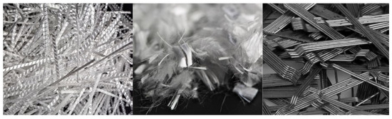
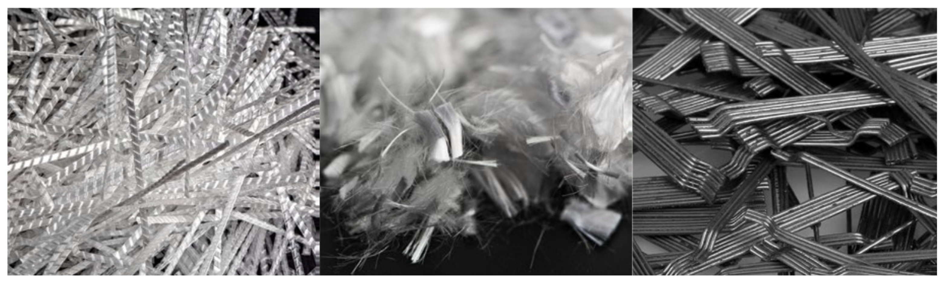
The three types of fibers used in the experimental program are illustrated in Figure 1.
Figure 1.
Types of fibers used in the experimental program: Polypropylene macrofibers and microfibers, and steel fibers.
According to [35]—a polymer fiber is defined as “a straight or deformed piece of oriented and cut material, suitable for incorporation into concrete or homogeneous mortar”. In this study, polymer fibers were used to investigate their influence on crack development and deformation behavior of reinforced concrete beams under flexural loading.
Synthetic macro polypropylene fibers typically possess a lower elastic modulus compared to steel fibers, ranging between 5 and 15 GPa. Despite their lower stiffness, these fibers are particularly effective during the early stages of concrete hardening, where they contribute significantly to the control and reduction in plastic shrinkage cracking. In addition to enhancing early-age performance, synthetic macrofibers offer excellent corrosion resistance and improve the overall ductility of the concrete matrix [35].
Polypropylene microfibers, on the other hand, are primarily employed to mitigate early-age shrinkage cracking and enhance fire resistance. This fire resistance is attributed to their low melting point of approximately 160 °C, which enables the formation of microchannels in the concrete structure, reducing internal vapor pressure during exposure to high temperatures [36].
In accordance with [37] steel fibers are described as “straight or deformed pieces of cold-drawn steel wire, or straight or deformed cut sheets of steel, produced from the melt”. Steel fibers are widely recognized for their high stiffness, tensile strength, and ability to bridge cracks, thereby significantly enhancing the post-cracking behavior and toughness of concrete.
The concrete mix compositions for the three experimental series—B1, B2, and B3—are summarized in Table 1 and Table 2.
Table 1.
Concrete mix design details for the three experimental series: B1, B2, and B3.
Table 2.
Fiber types and their dosages in concrete mixes (kg/m3).
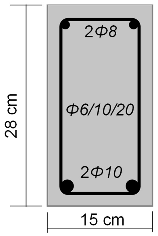
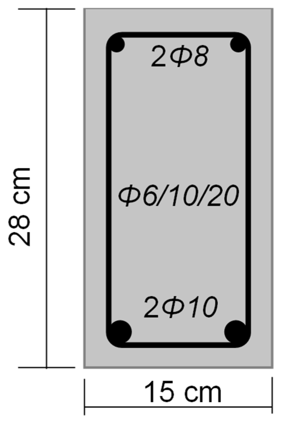
In all three series, the longitudinal reinforcement consisted of B500B steel, while the stirrups were made of S 240/360 steel. The test beams had cross-sectional dimensions of 15 × 28 cm. The reinforcement layout included 2Ø10 mm bars in the tension zone and 2Ø8 mm bars in the compression zone, with Ø6 mm stirrups placed at intervals of 10 cm in the shear zones and 20 cm in the central zone. The reinforcement arrangement is illustrated in Figure 2.
Figure 2.
Beams cross-section.
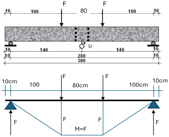
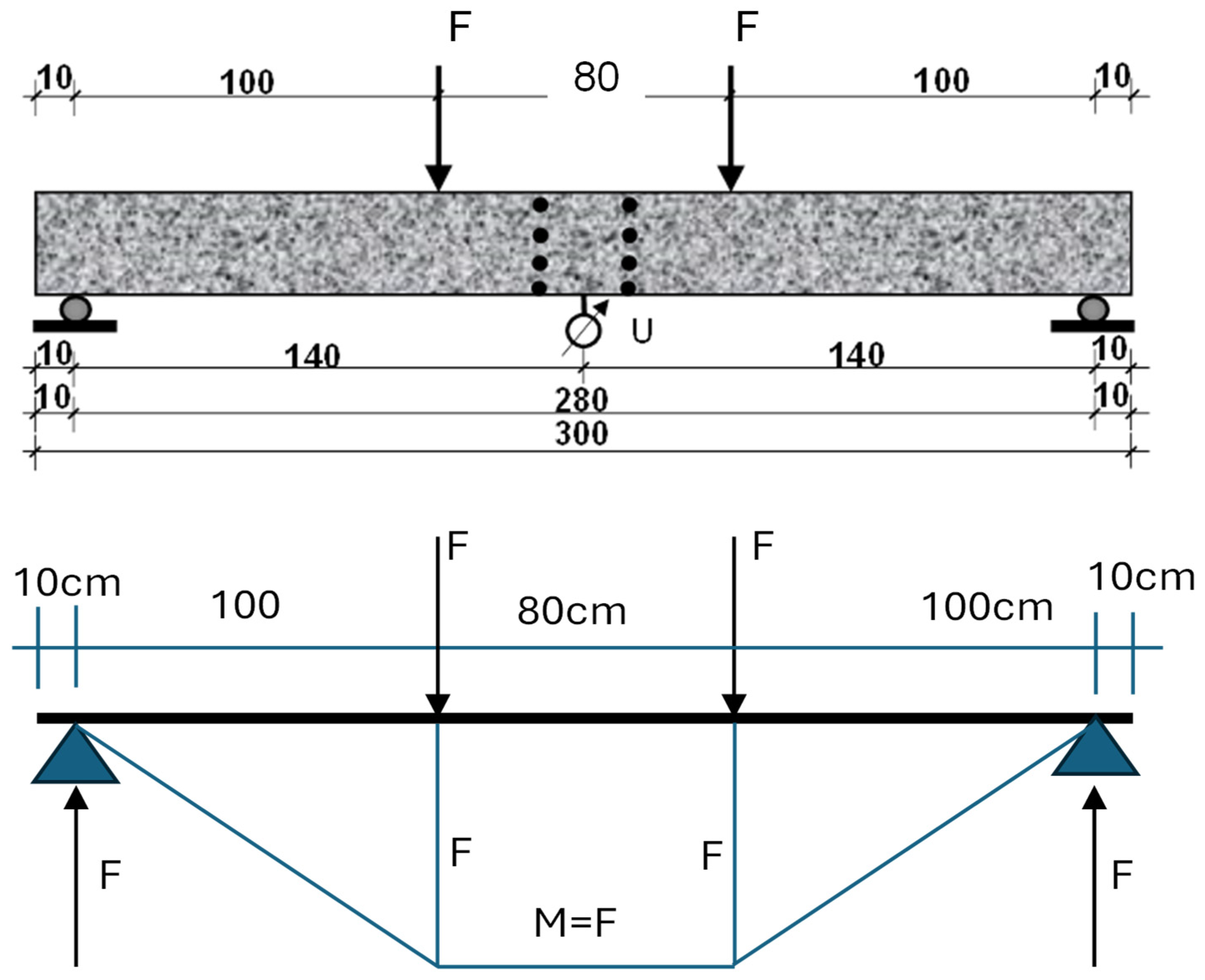
The beams were designed as simply supported beams subjected to two symmetrical point loads, creating a region of pure bending at mid-span, as shown in Figure 3.
Figure 3.
Static scheme of the beam, locations of measurement points for assessing deformation characteristics, and corresponding bending moment diagrams.
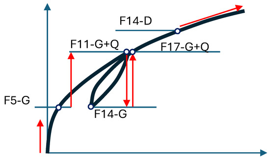
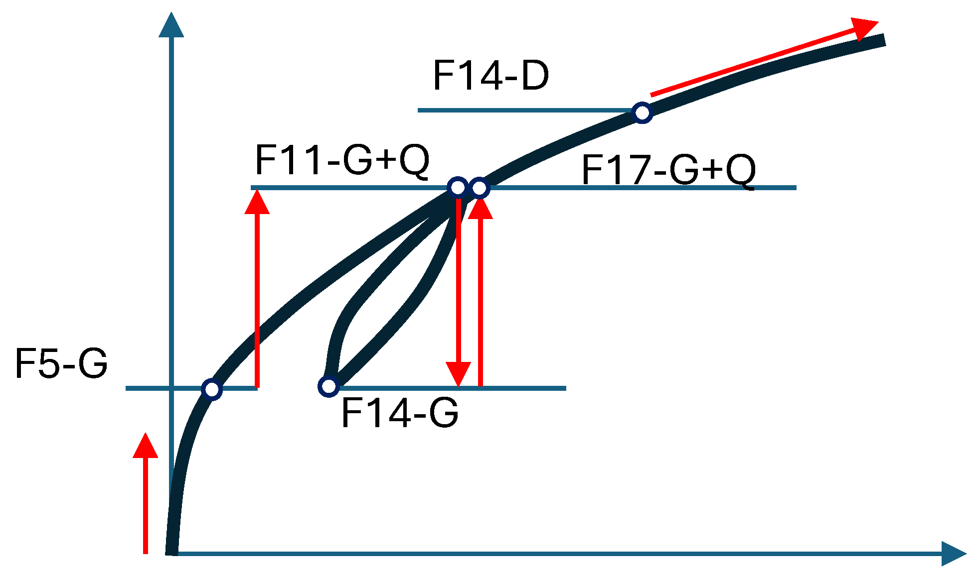
The loading protocol applied during beam testing is summarized in Table 3. The notation F5 to F27 refers to successive load increments applied symmetrically to the beams. The symbol G denotes the self-weight of the beam, while G + Q represents the combination of permanent and variable loads corresponding to service-level conditions. This stepped loading–unloading procedure was adopted to monitor deformation recovery, crack development, and stiffness degradation.
Table 3.
Loading and unloading process, loading until breaking.
F5 to F27 denote the loading phases applied during the cyclic loading–unloading process up to beam failure (Figure 4). The loading procedure started from zero load and increased up to phase F5, corresponding to the permanent load level (G). The load was then further increased to phase F11, representing the combined permanent and variable load (G + Q). Subsequently, the beam was unloaded to phase F14, again corresponding to the permanent load level (G). Thereafter, the load was increased incrementally to phase F17 (G + Q), followed by continuous loading until failure, which corresponds to the final phases up to F27.
Figure 4.
Cyclic loading–unloading of the beam from permanent load (G) to combined load (G + Q) up to failure.
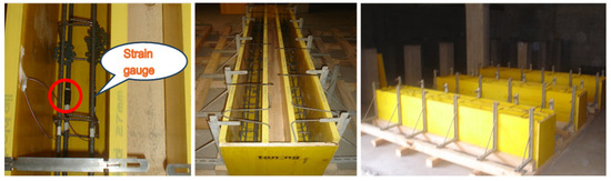
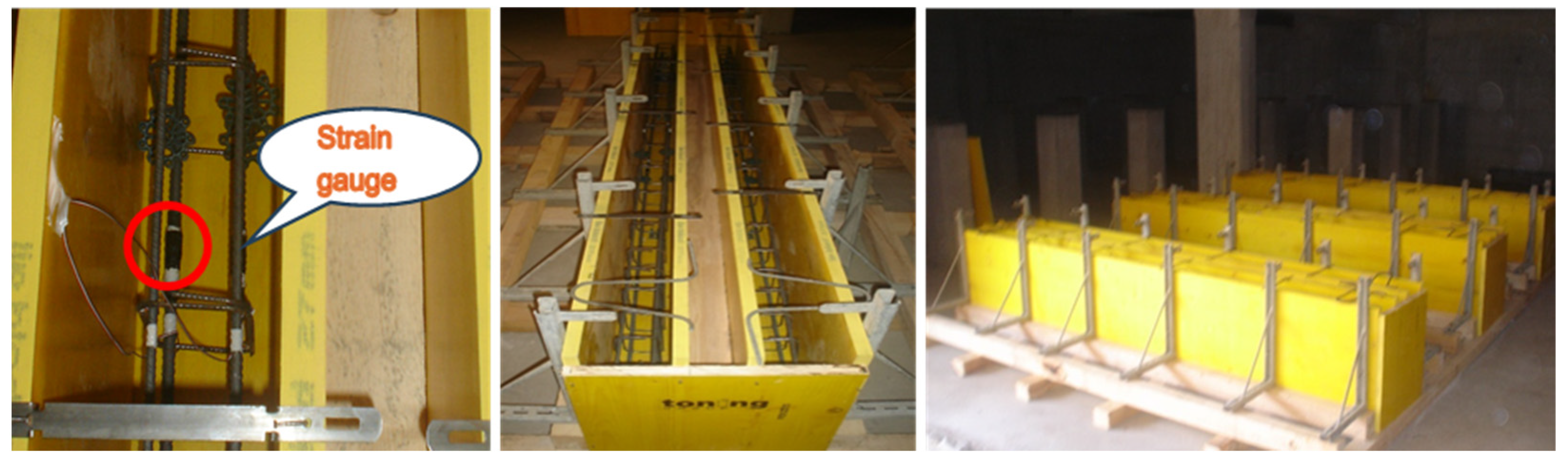
The beam formwork and reinforcement setup are presented in Figure 5.
Figure 5.
Framework and reinforcement of beams, with strain gauges mounted on the reinforcement.
A simple plasticizer was used in the mix design. This admixture is routinely employed by the concrete producer to facilitate equipment protection and to improve the workability of the concrete at a minimal dosage. Therefore, although no high-range water-reducing admixture was used, a conventional plasticizer was included to ensure adequate processing of the fiber-reinforced concrete.
2.2. Testing Methods
The compressive strength of the concrete was determined on 150 × 150 × 150 mm cubic specimens, in accordance with [38].
The tensile strength from cracking was evaluated in accordance with [39], using both cylindrical specimens measuring 150 × 300 mm and cubic specimens of 150 × 150 × 150 mm. During testing, the load was applied at a rate of 50 kPa/s, with a measurement sensitivity of 0.5 kN.
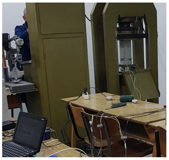
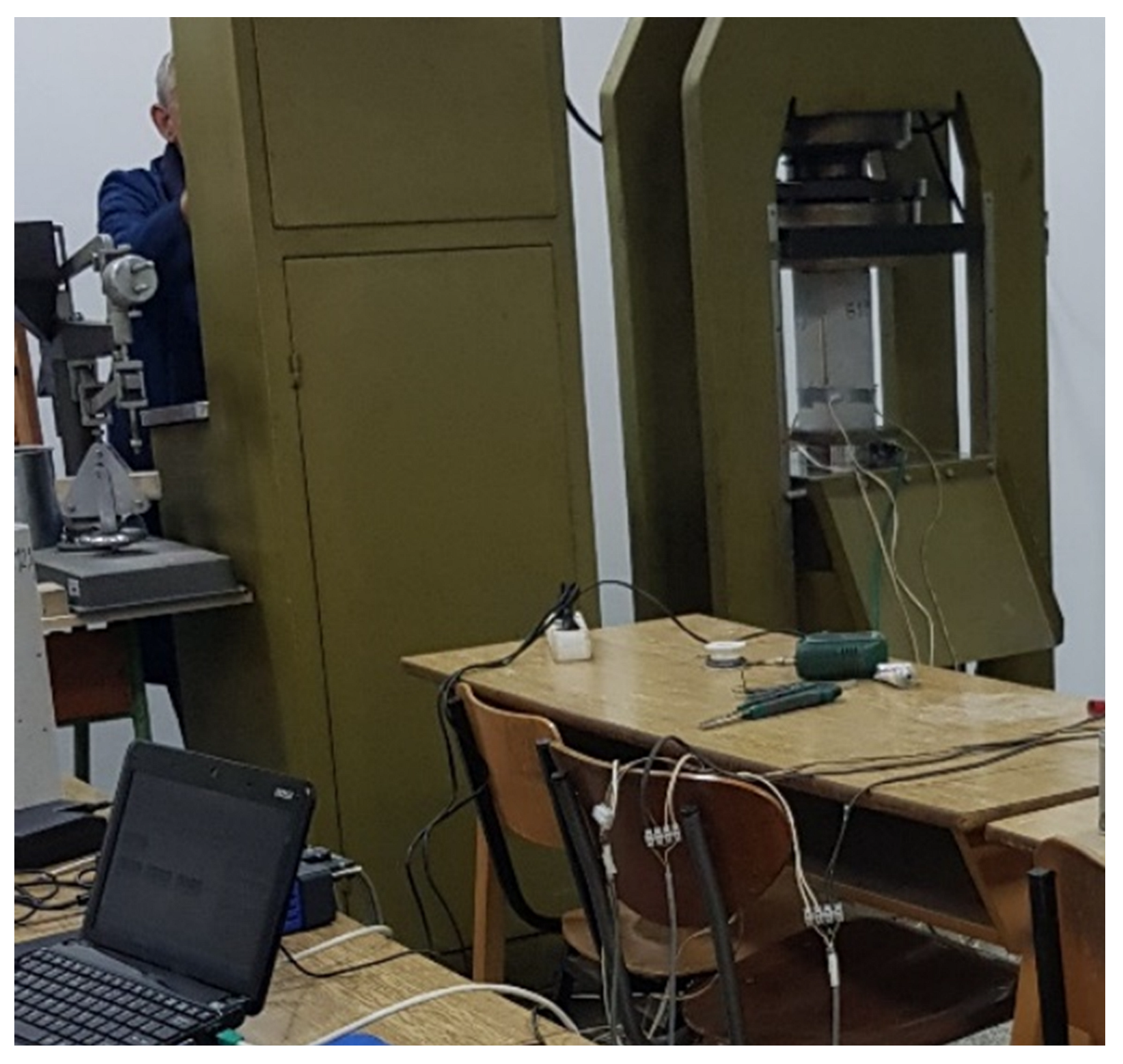
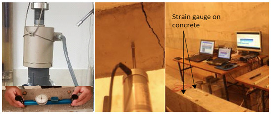
The modulus of elasticity was determined on cylindrical specimens measuring 150 × 300 mm, in accordance with [40]. The testing procedure involved the use of strain gauges and a force-measuring press, both connected to a datalogger for continuous recording of load and deformation data. The experimental setup is illustrated in Figure 6.
Figure 6.
Experimental setup for modulus of elasticity testing using strain gauges and a force-measuring press connected to a datalogger.
One of the key parameters evaluated for steel fiber-reinforced concrete is its flexural tensile strength, which provides a critical measure of the material’s post-cracking behavior and toughness [41,42].
Flexural testing was conducted in accordance with the recommendations of RILEM TC-162-TDF [9], which assesses the tensile behavior of steel fiber-reinforced concrete either through the area under the load–deflection curve or by evaluating the load-bearing capacity at the mid-span of a simply supported beam, where a controlled crack opening or specific shear condition is induced.
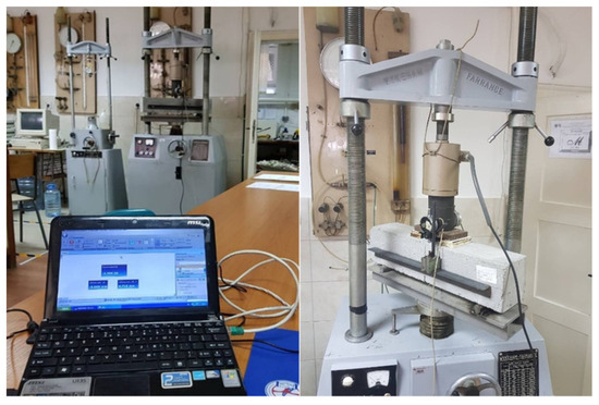
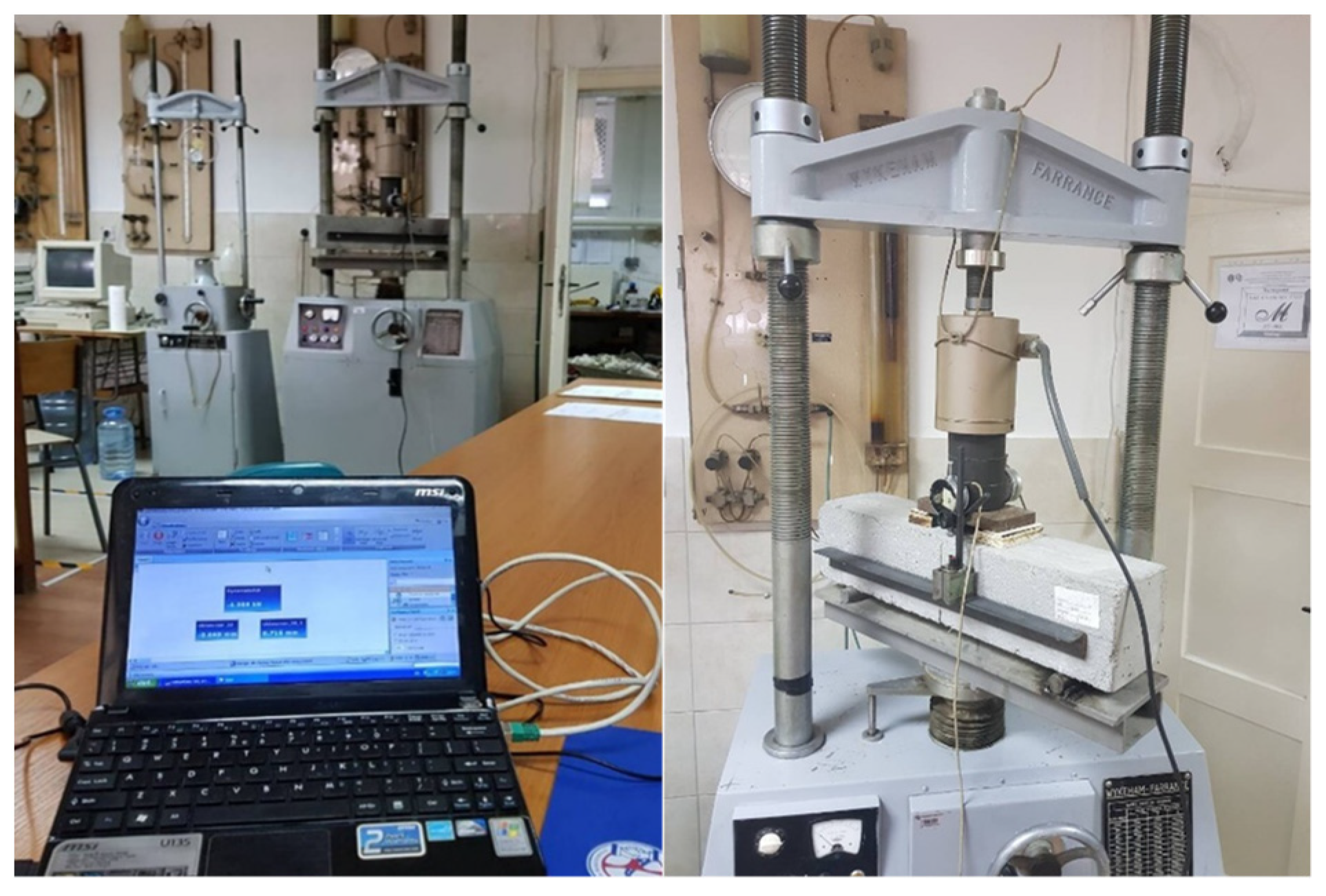
The flexural tests were performed using a hydraulic jack HPM3000 (ZRMK, Ljubljana, Slovenia). Notched concrete prisms with a cross-section of 150 × 150 mm, a total length of 600 mm, and a span of 500 mm were tested. The deflection was applied at a constant rate of 0.2 mm/min using a Wykeham Farrance testing machine (Wykeham Farrance, London, UK) with a load capacity of 50 kN. All load and displacement data were continuously recorded using a data acquisition system produced by Hottinger Baldwin-HBM (Germany) (Figure 7).
Figure 7.
Flexural strength testing setup for specimens reinforced with polypropylene microfibers.
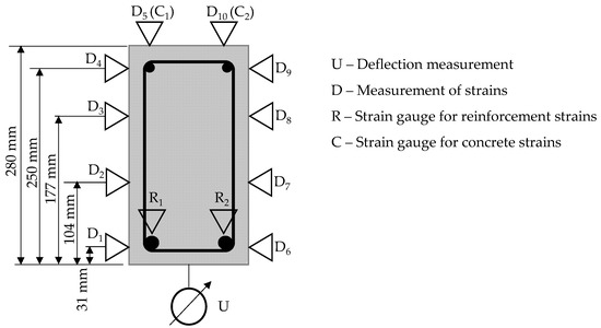
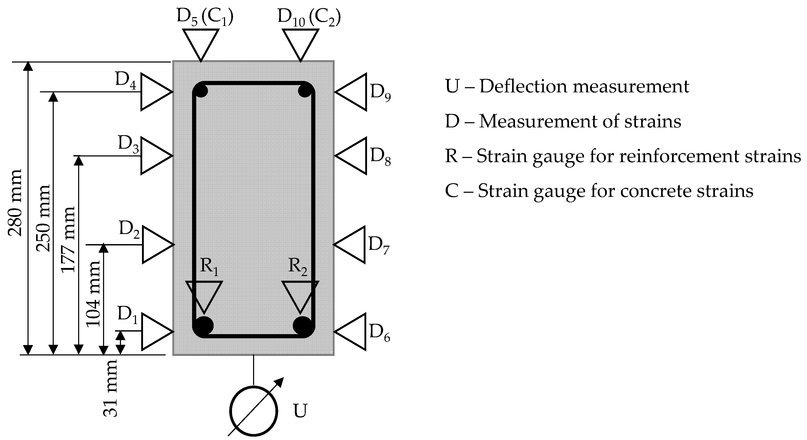
During the failure process at time t0, as outlined in the force application phases presented in Table 3, a total of six beams were tested, with two beams per series: Series B1, Series B2, and Series B3. PA data acquisition and processing system from Hottinger Baldwin-HBM (Germany) was employed to record key parameters, including applied force, deflection at mid-span, and deformations in the tension zone (reinforcement) and compression zone (concrete) of the beams (Figure 8). The piston for load application, LVDTs, and strain gauges were sourced from Kyowa (Japan).
Figure 8.
Measurement points for deflections using LVDTs, strain measurements with a mechanical deformmeter (D), and strain measurements in the reinforcement (R) and concrete (C) using strain gauges.
At each load increment, deformations at marked beam positions (e.g., D5-D10) were measured using a mechanical deformation meter (Hugenberger, Switzerland) with a 250 mm base. Mechanical measurement was recorded using a dial gauge manufactured by Stopan (Italy). Additionally, the crack width at each load step was measured using a crack measurement microscope (Controls, Italy). The piston for load application, LVDTs, and strain gauge tapes were provided by Hottinger Baldwin-HBM (Figure 9).
Figure 9.
Piston for load application, LVDTs, and strain gauges provided by Hottinger Baldwin-HBM.
2.3. Numerical Modeling in DIANA
A nonlinear finite element model was developed using the DIANA FEA software to simulate the structural response of the tested reinforced concrete beams and to support the interpretation of experimental results. The numerical model was designed to reproduce the experimental boundary conditions, loading scheme, and material behavior as closely as possible.
Concrete was modeled using a total strain-based smeared crack formulation with rotating crack orientation. This approach allows crack directions to evolve with the principal strain directions and is suitable for capturing distributed cracking in reinforced concrete elements. The linear elastic properties of concrete were defined by a Young’s modulus of 33,550 N/mm2 and a Poisson’s ratio of 0.20.
The tensile behavior of the fiber-reinforced concrete was defined using the built-in fib fiber-reinforced concrete tensile model in DIANA. A CMOD-based multilinear stress–crack opening relationship was adopted to represent the post-cracking behavior of the material. The model was characterized by an initial uniaxial tensile strength of 1.8 N/mm2, followed by residual tensile strengths defined at increasing crack mouth opening displacements, up to an ultimate CMOD of 8 mm. The crack bandwidth was specified using the Rots formulation, and stiffness degradation was governed by a damage-based reduction model.
The compressive behavior of concrete was described using a parabolic stress–strain relationship with a compressive strength of 30 N/mm2 and a compressive fracture energy of 30.1 N/mm. The influence of lateral cracking on compressive strength was accounted for using the reduction model proposed by [43], with a lower bound reduction factor of 0.4. No confinement enhancement was considered.
Steel reinforcement was assigned linear elastic properties with a Young’s modulus of 200,000 N/mm2 and a Poisson’s ratio of 0.20. Where interaction between support and concrete was idealized, a two-dimensional line interface was employed with a normal stiffness modulus of 1000 N/mm3 and a shear stiffness modulus of 10 N/mm3.
Fiber reinforcement was not modeled discretely. Instead, its mechanical contribution was incorporated implicitly through the modified post-cracking tensile behavior of the concrete, which is consistent with smeared-crack modeling strategies commonly adopted for fiber-reinforced concrete beams.
3. Results and Discussion
3.1. Mechanical Properties
Table 4 presents the results of compressive strength testing, splitting tensile strength, and modulus of elasticity measurements for the three concrete series (B1, B2, B3).
Table 4.
Results of mechanical characteristics: compressive strength, splitting tensile strength and modulus of elasticity.
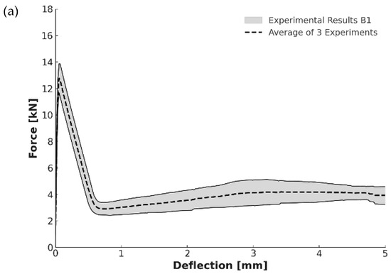
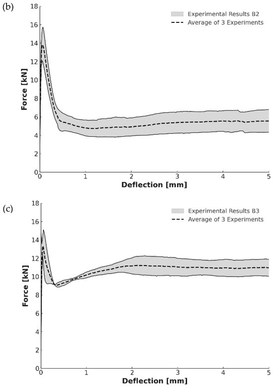
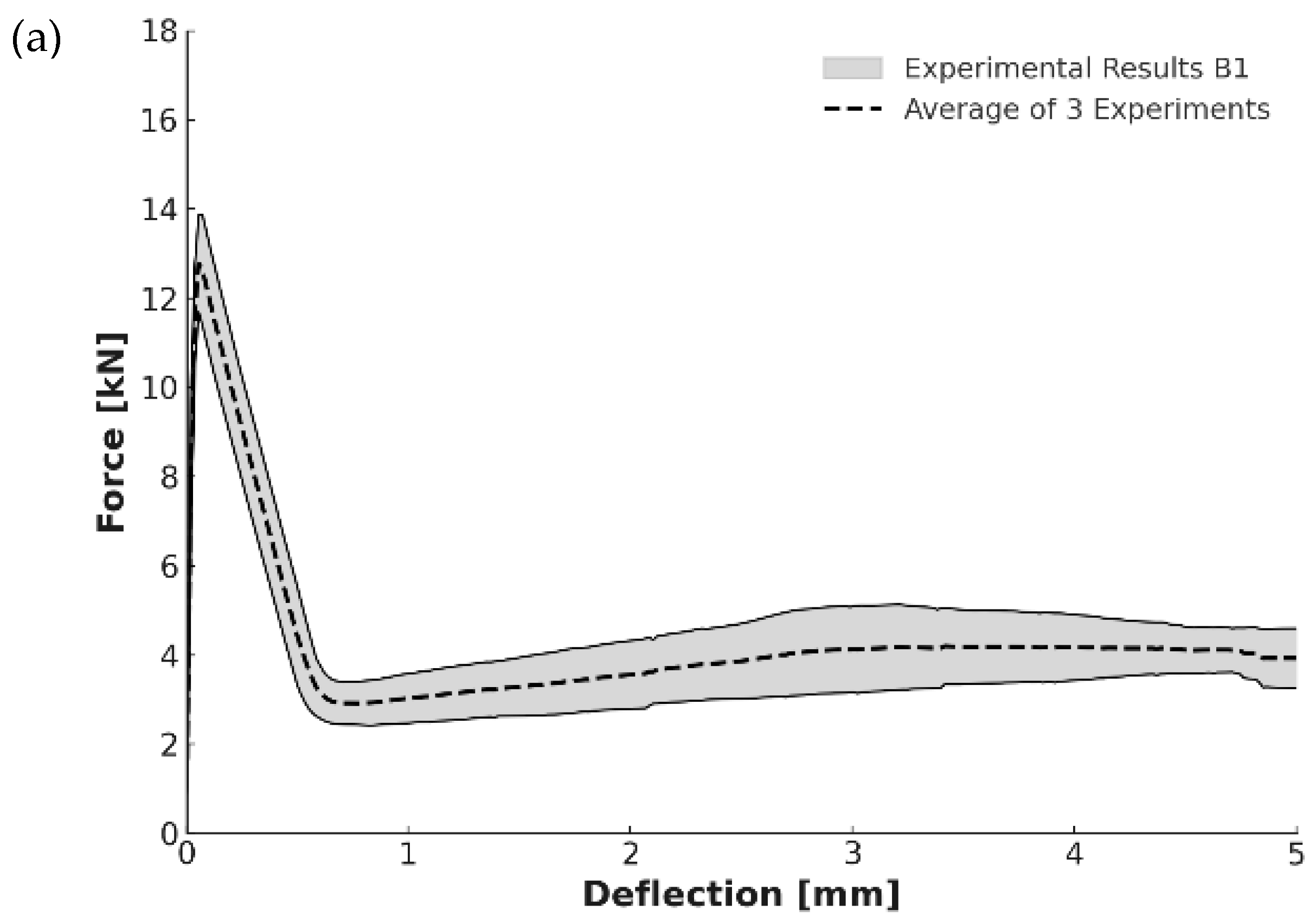
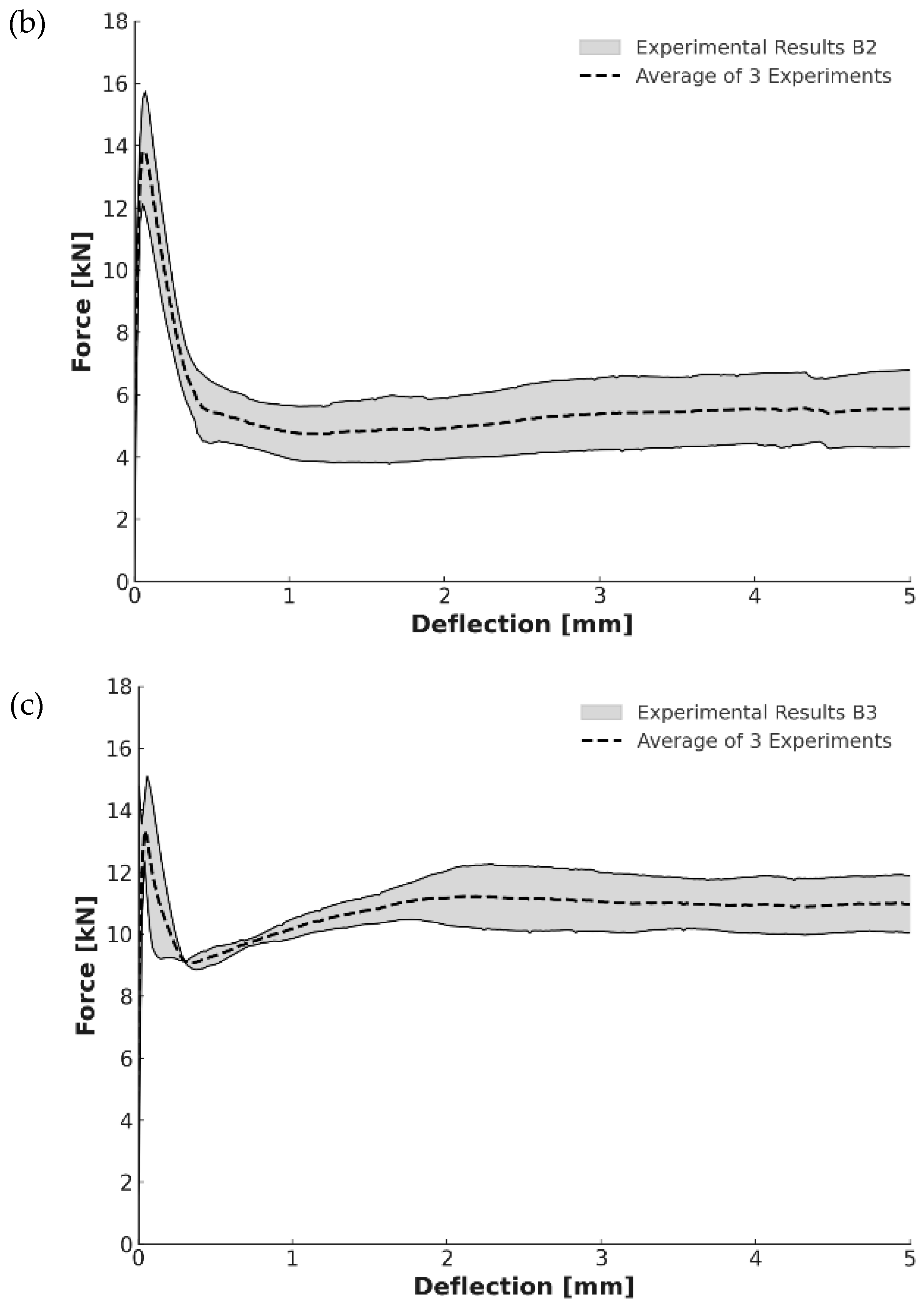
Figure 10 presents a graphical comparison of the results from the RILEM bending prism tests for the three concrete series (B1, B2, B3).
Figure 10.
Results of the RILEM bending prism test for (a) Serie B1; (b) Serie B2; (c) Serie B3.
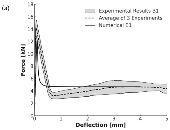
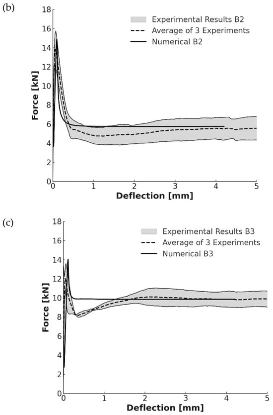
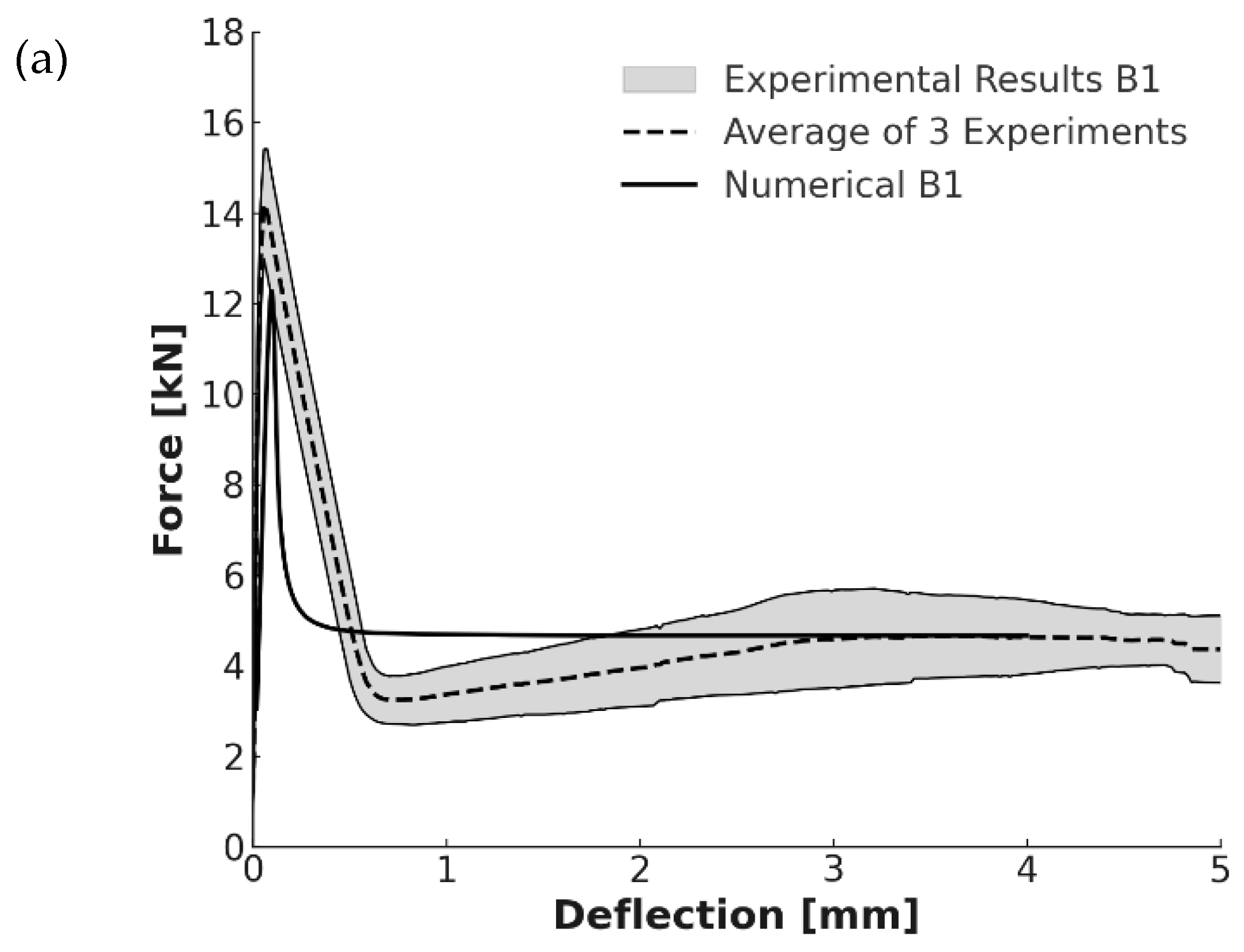
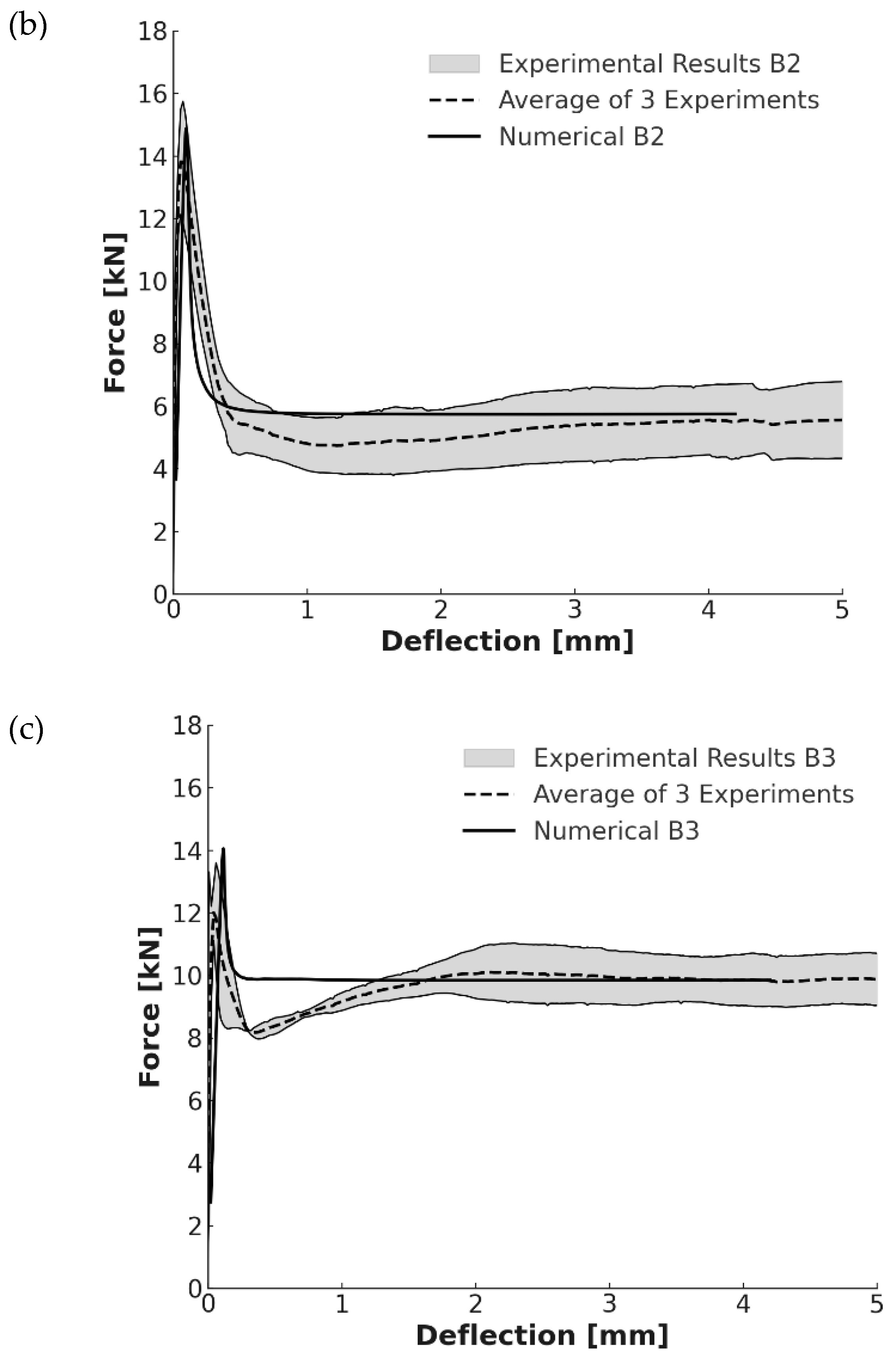
The experimental results obtained from the RILEM bending prism tests were further analyzed using the finite element model described in Section 2.3. Numerical simulations performed in DIANA were used to reproduce the load–deflection response and to compare the predicted behavior with the experimental measurements (Figure 11). The comparison shows good agreement between the measured and simulated responses, indicating that the DIANA model accurately represents the beam’s structural behavior.
Figure 11.
Comparison of experimental results with numerical ones for (a) Serie B1; (b) Serie B2; (c) Serie B3.
3.2. Experimental Strain Measurements in Concrete and Reinforcement
To assess the strains in both the concrete and the reinforcement, two beams from each of the three concrete series were tested. The experimental program comprised three-beam series, each including two specimens: Series B1 (B1-1 and B1-2), reinforced with macro polypropylene fibers; Series B2 (B2-1 and B2-2), incorporating a combination of micro and macro polypropylene fibers; and Series B3 (B3-1 and B3-2), reinforced with micro polypropylene, macro polypropylene, and steel fibers.
The strains in both concrete and reinforcement for the three-beam series are presented graphically. Measurements were obtained from both sides of each beam, and average values are also reported. Strains in the reinforcement (tension zone) were measured at positions D1 and D6 using a mechanical deformometer, while strains in the concrete (compression zone) were recorded at positions D5 and D10. Strains in the reinforcement bars (R) and in the concrete (C) were measured using strain gauges. The strain results are presented for each measurement position throughout the loading process for all beam series. In addition, strain measurements at the cross-sectional level—3.1 cm from the center of the reinforcement for R and 2.8 cm from the top of the beam for C—are reported, as illustrated in Figure 8.
The notation used in the figures refers to the measurement location and specimen number. The prefix “C” denotes strain measurements in concrete, while “R” denotes strain measurements in reinforcement. The first number indicates the beam series, and the second number refers to the specimen number within that series.
3.2.1. Beams with Macrofibers: Series B1
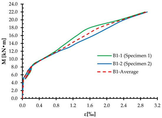
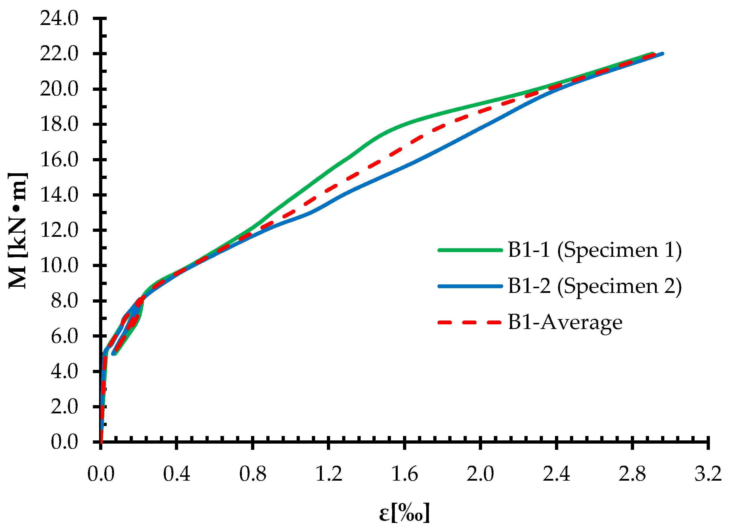
Figure 12 presents the average values of strains in concrete for the concrete beams reinforced with (B1), while Figure 13 shows the average values of strains in reinforcement for the same beams.
Figure 12.
Concrete strain distribution in macrofiber-reinforced concrete beams.
Figure 13.
Reinforcement strain distribution in macrofiber-reinforced concrete beam.
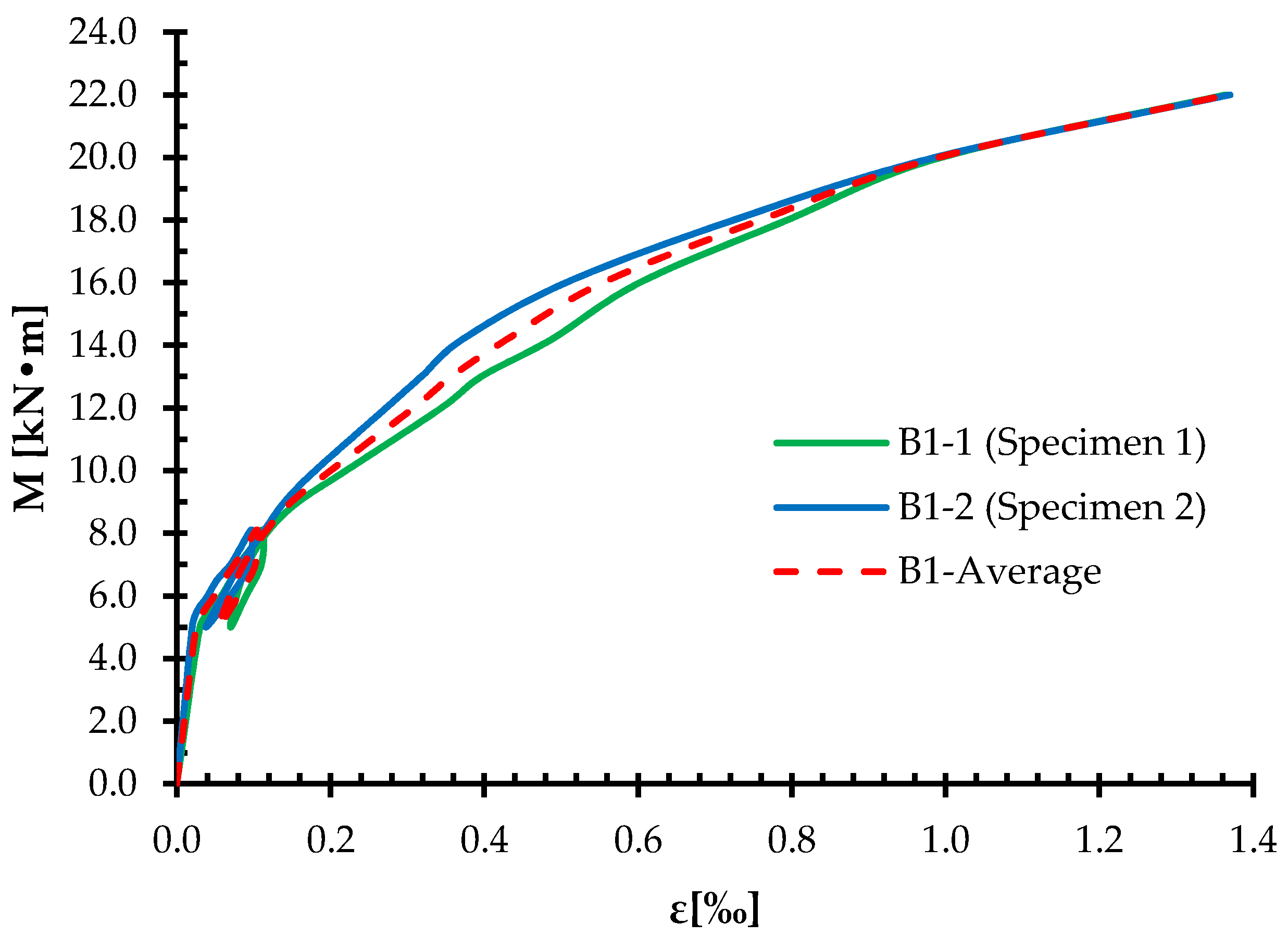
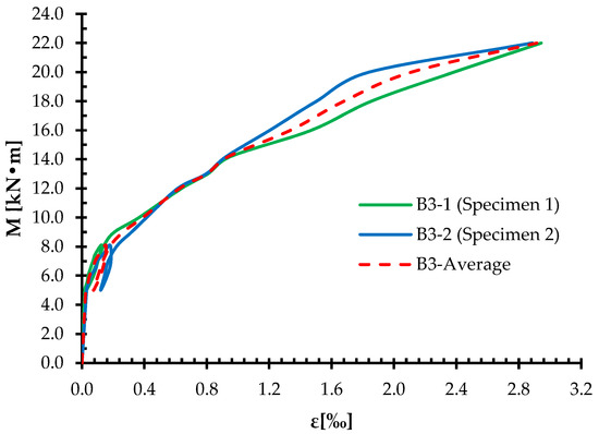
With reference to the static scheme and the points of load application shown in Figure 3, the bending moment at the load application point is equal to the applied force (M = F). Consequently, the moment–strain results presented herein are effectively equivalent to force–displacement results, and both representations describe the same structural response. Therefore, moment–strain curves are adopted in this study instead of force–strain curves.
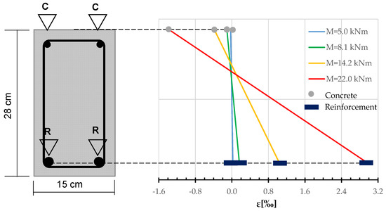
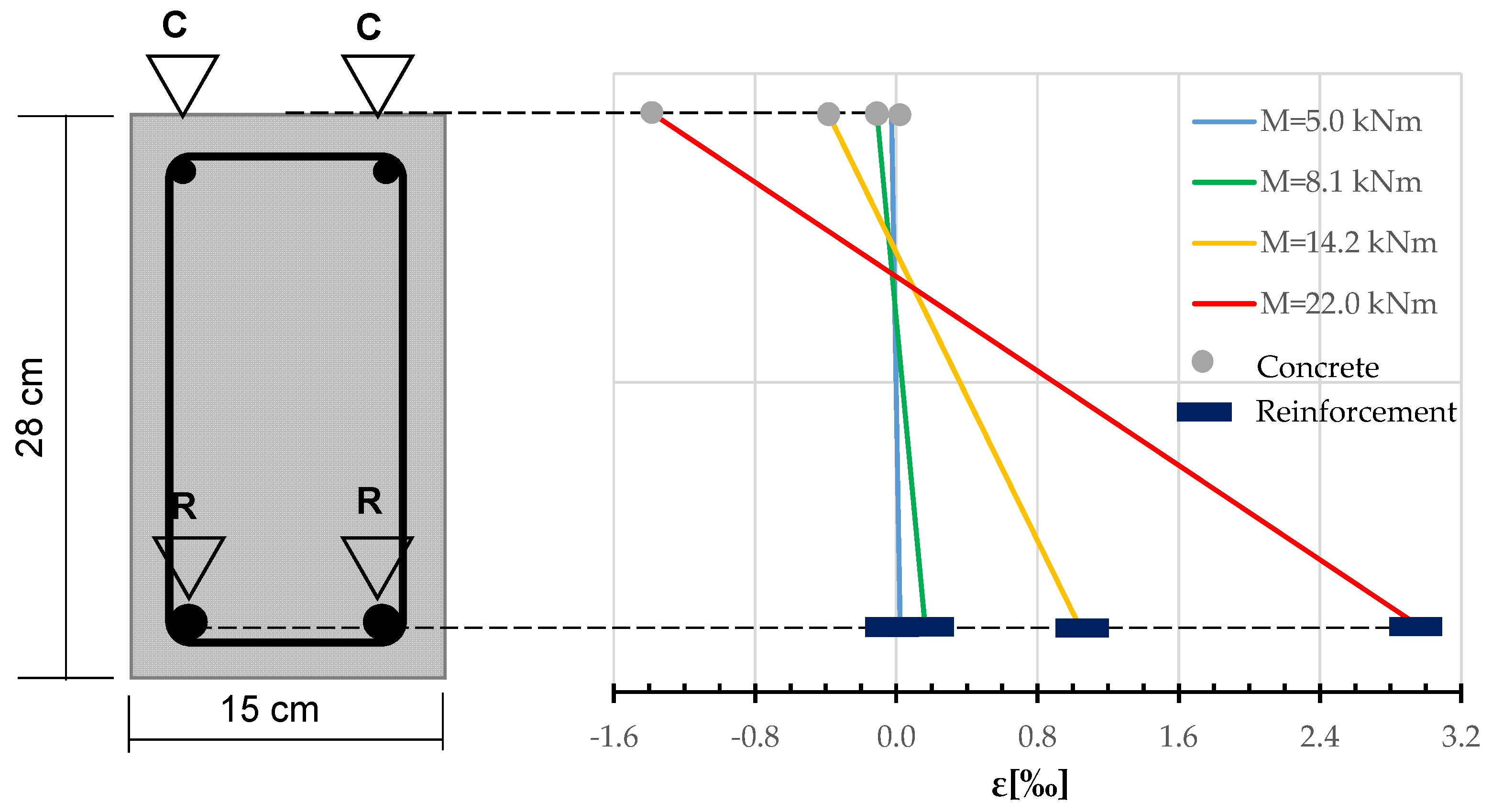
Figure 14 presents the average values of concrete strains and reinforcement strains at the height for both beams made of macrofiber reinforced concrete (Series B1).
Figure 14.
Strain distribution in reinforcement and concrete for a macrofiberreinforced concrete beam.
The strain distributions obtained for Series B1 indicate a stable and nearly linear increase in both concrete compressive strains and reinforcement tensile strains up to service load levels. The macro polypropylene fibers contributed to a relatively uniform strain development along the beam length, limiting sudden strain localization in the early loading stages. However, as loading progressed toward higher force levels, an increased rate of strain accumulation was observed, particularly in the reinforcement, indicating the onset of crack localization and stiffness degradation. This behavior suggests that while macro polypropylene fibers improve crack control compared to plain concrete, their contribution to post-cracking stiffness and deformation capacity remains limited.
3.2.2. Beams with Macro and Microfibers: Series B2
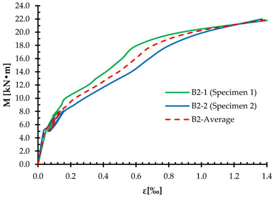
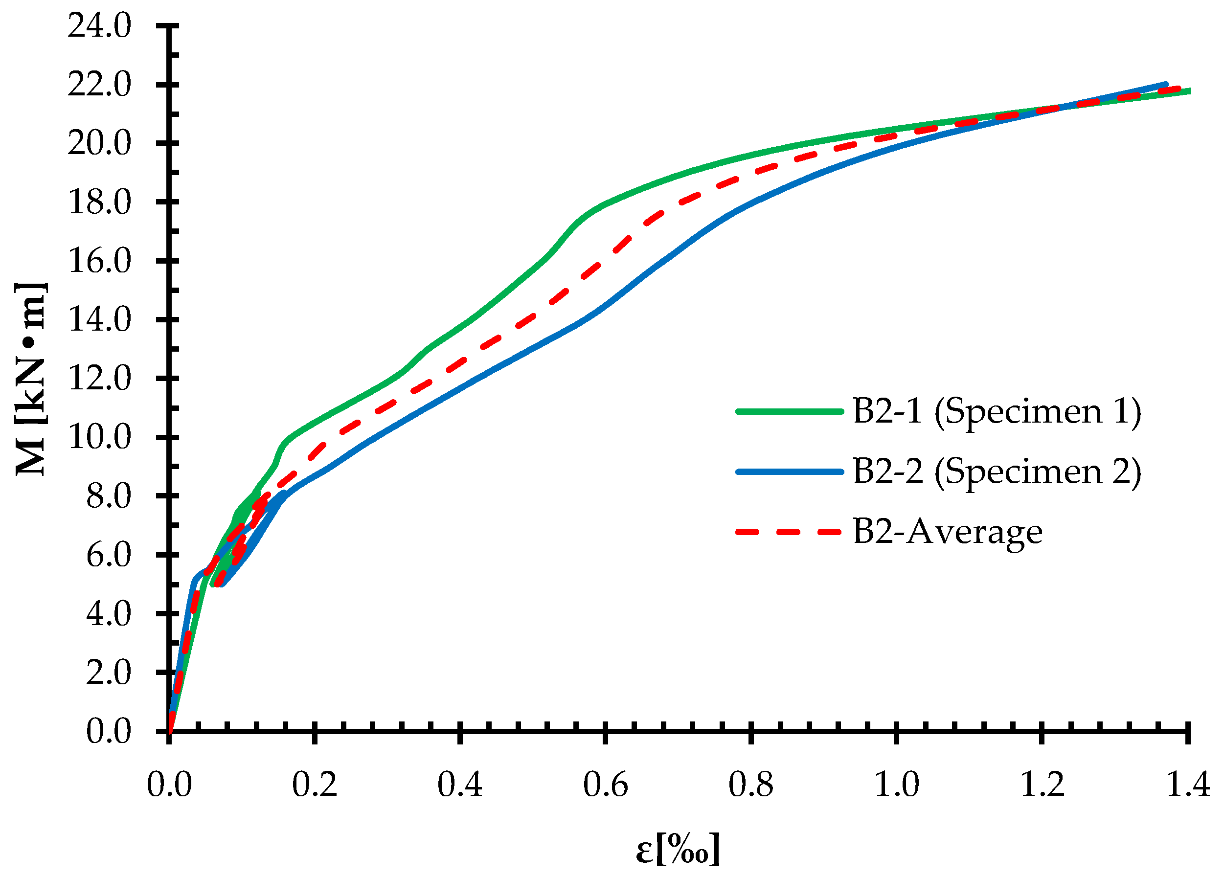
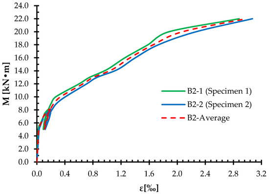
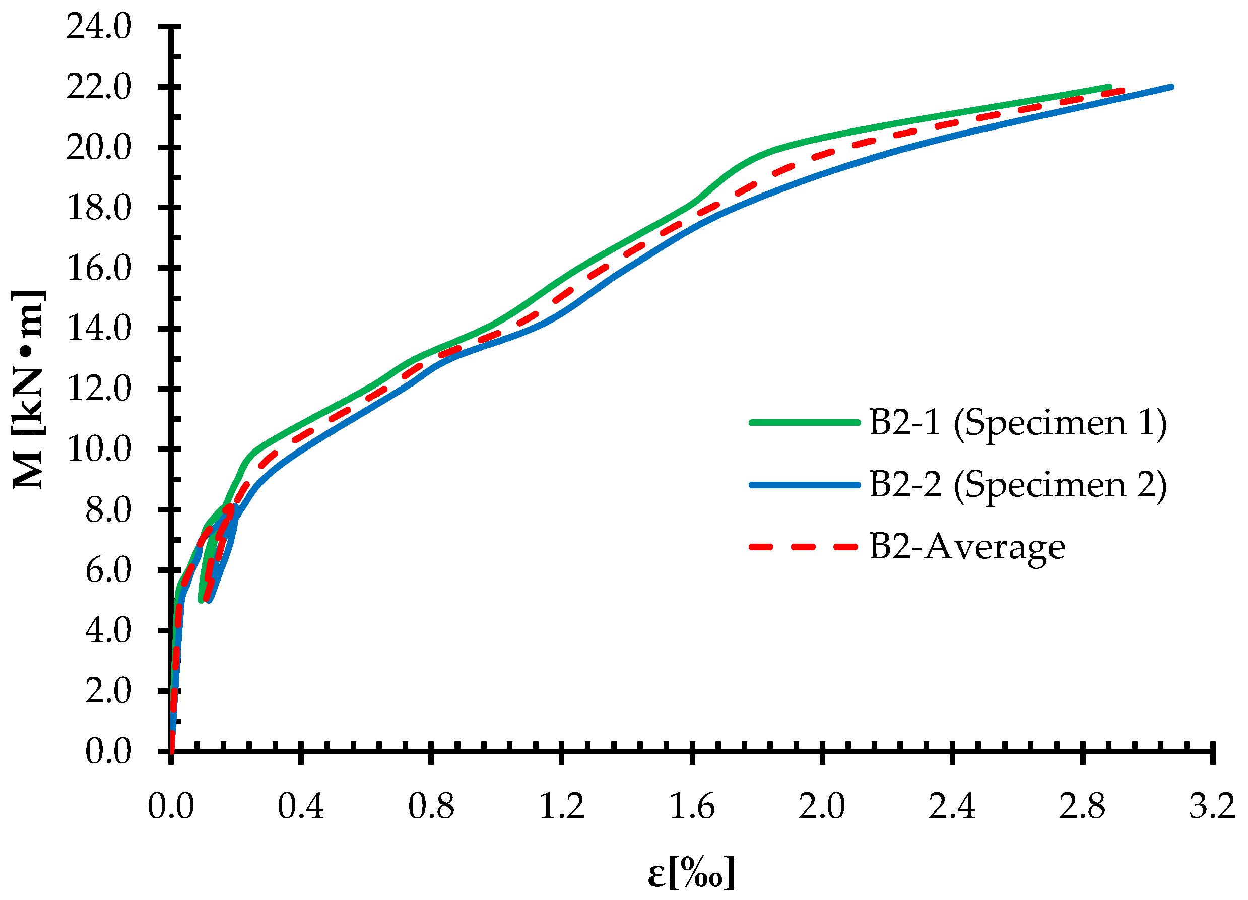
Figure 15 presents the average values of strains in concrete, while Figure 16 shows the average values of strains in the reinforcement.
Figure 15.
Concrete strain distribution in micro and macrofiber-reinforced concrete beams.
Figure 16.
Reinforcement strain distribution in micro and macrofiber-reinforced concrete beams.
Figure 17 presents the average values of concrete strains and reinforcement strains at the height for both beams made of micro and macrofiber-reinforced concrete beams (Series B2).
Figure 17.
Strain distribution in reinforcement and concrete for a micro and macrofiber-reinforced concrete beams.
Compared to Series B1, beams reinforced with a combination of micro and macro polypropylene fibers (Series B2) exhibited a more gradual evolution of strains in both concrete and reinforcement. The presence of microfibers contributed to improved crack distribution and delayed strain concentration, particularly in the compression zone of the concrete. This effect resulted in slightly reduced reinforcement strain growth at comparable load levels, indicating enhanced deformation compatibility between concrete and reinforcement. Nevertheless, the overall strain reduction remained moderate, suggesting that the addition of microfibers alone has a limited influence on the global flexural deformation behavior of reinforced concrete beams.
3.2.3. Beams with Macro, Micro, and Steel Fibers: Series B3
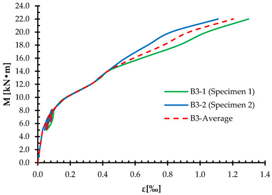
Figure 18 presents the average values of strains in concrete, while Figure 19 shows the average values of strains in the reinforcement.
Figure 18.
Concrete strain distribution in concrete beams reinforced with micro, macro, and steel fibers.
Figure 19.
Reinforcement strain distribution in concrete beams reinforced with micro, macro, and steel fibers.
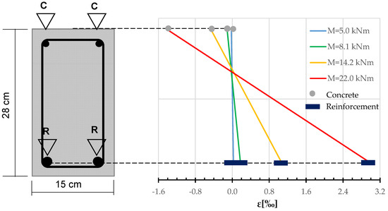
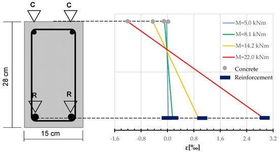
Figure 20 presents the average concrete and reinforcement strains along the height of both beams made of micro-, macro-, and steel fiber-reinforced concrete (Series B3).
Figure 20.
Strain distribution in reinforcement and concrete for a concrete beam reinforced with micro, macro, and steel fibers.
A markedly different strain response was observed for Series B3, which incorporated steel fibers in addition to micro and macro polypropylene fibers. The strain curves demonstrate a more distributed deformation pattern and a slower rate of strain increase in both concrete and reinforcement, particularly beyond service load levels. The steel fibers effectively enhanced crack-bridging capacity, leading to improved stress redistribution and delayed stiffness degradation. As a result, Series B3 beams exhibited higher deformation capacity and a more ductile response compared to Series B1 and B2, confirming the significant contribution of steel fibers to post-cracking behavior under flexural loading.
3.2.4. Comparison of Beam Performance for Fiber-Reinforced Concretes B1–B3
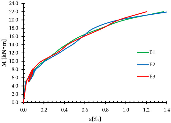
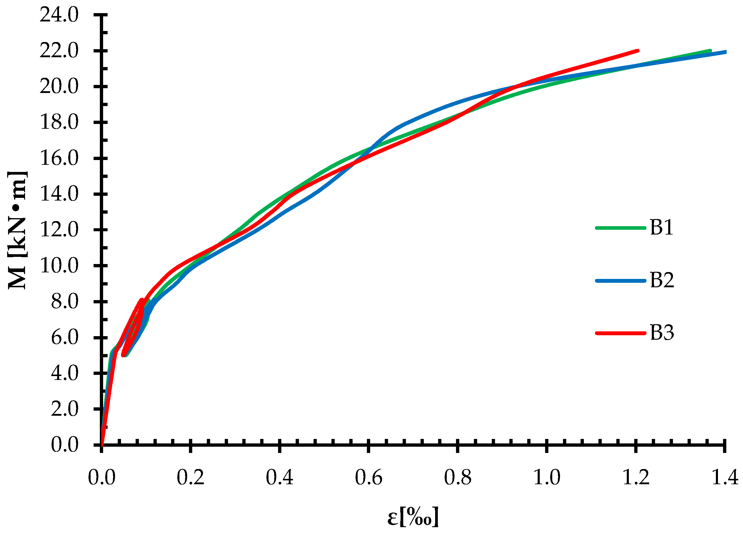
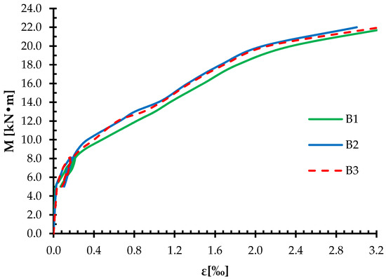
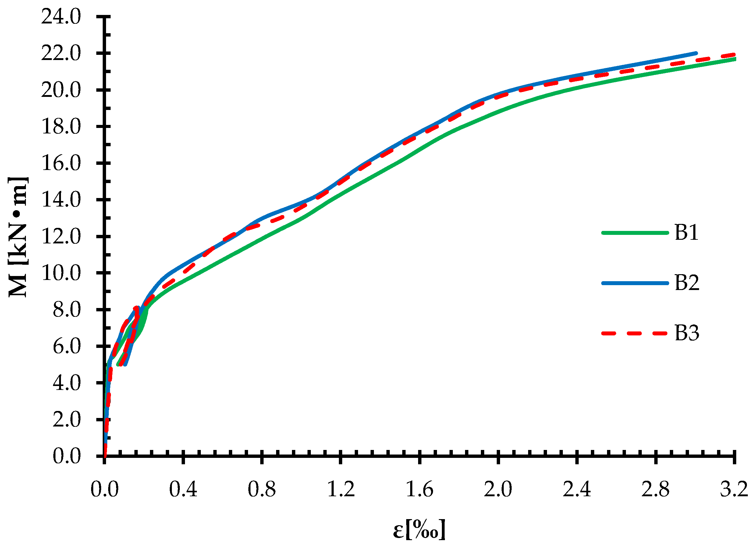
Figure 21 presents a comparison of the results for strains in concrete, while Figure 22 shows the comparison of the results for strains in reinforcement.
Figure 21.
Comparison of concrete strain results for beams of three concrete types: B1, B2, and B3.
Figure 22.
Comparison of reinforcement strain results for beams of three concrete types: B1, B2, and B3.
The comparative strain responses presented in Figure 21 and Figure 22 reveal that the influence of fiber type becomes more pronounced with increasing load level. At service load conditions, the strain values in both concrete and reinforcement are relatively similar for all three series, indicating comparable stiffness in the early loading stages. As loading progresses beyond crack initiation, Series B3 exhibits a more gradual increase in strains compared to Series B1 and B2, reflecting improved stress redistribution and delayed strain localization due to the presence of steel fibers.
The largest differences in deformation are observed at higher load levels, where Series B3 shows increased deformation capacity accompanied by more stable strain development. In contrast, Series B1 and B2 display a steeper strain increase, particularly in the reinforcement, indicating earlier stiffness degradation. These observations confirm that micro polypropylene fibers alone provide only limited improvement in global deformation behavior, whereas the inclusion of steel fibers plays a decisive role in enhancing ductility, strain compatibility, and post-cracking performance of reinforced concrete beams.
3.3. Crack Pattern and Failure Mode
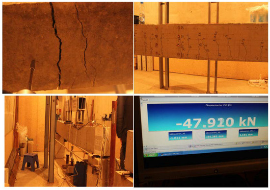
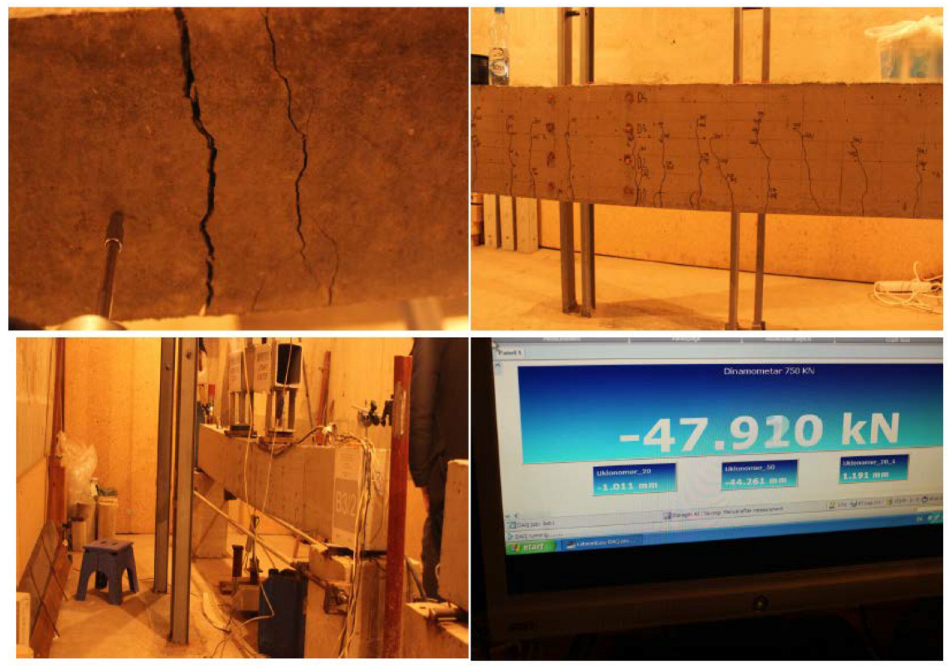
Figure 23 presents the crack patterns observed in beams B1, B2, and B3 at different loading stages. Beams reinforced with polypropylene fibers exhibited distributed cracking with reduced crack widths, while beams containing steel fibers showed more pronounced crack bridging and delayed localization. The hybrid fiber system enhanced post-cracking integrity and contributed to improved deformation capacity.
Figure 23.
Representative images of failed beams and the corresponding crack patterns.
4. Conclusions
The experimental results from the comparison of deformation behavior, compressive strength, splitting tensile strength, and modulus of elasticity for concrete beams reinforced with different fiber combinations (macrofibers, microfibers, and steel fibers) provide significant insights into the mechanical performance of fiber-reinforced concrete (FRC). Based on the data presented, the following conclusions can be drawn:
Deformation Behavior: The strain results for both concrete and reinforcement demonstrated a clear influence of fiber type and combination on deformation characteristics. The largest differences in strain were observed between Series B2 (macro + microfibers) and B3 (macro + micro + steel fibers), with average discrepancies of 6.3% in concrete strain and 10.3% in reinforcement strain. This indicates that the inclusion of steel fibers significantly enhanced the load transfer and deformation behavior of both the concrete matrix and the reinforcement.
Beams reinforced with hybrid fibers (B3) exhibited a more ductile failure mode characterized by distributed cracking and delayed stiffness degradation compared to beams reinforced solely with polypropylene fibers.
Effect of Fiber Combination on Strain: When comparing Series B1 (macrofibers) to B3 (macro + micro + steel fibers), moderate differences in deformation were observed, with 3.1% for concrete strain and 6.0% for reinforcement strain. This suggests that the combination of macro, micro, and steel fibers offers improved strain compatibility and load-bearing performance, especially in reinforced concrete beams subjected to flexural loading. On the other hand, the smallest differences were found between Series B1 and B2 (macro + microfibers), with 1.2% in concrete and 3.9% in reinforcement strain, highlighting that the addition of microfibers alone slightly improves the strain behavior compared to macrofibers alone.
Mechanical Properties: The compressive strength results revealed a significant variation, particularly between Series B2 and B3, where the addition of steel fibers resulted in a substantial increase in strength. The average compressive strength increase for Series B3 over B2 was 28.84%. Similarly, the modulus of elasticity showed a notable variation, with the largest difference between Series B1 and B2, at 20.07%, indicating a considerable impact of fiber type on concrete stiffness. In contrast, Series B1 and B3 exhibited a smaller difference in modulus of elasticity (2.21%), suggesting that the incorporation of steel fibers has a more moderate impact on stiffness compared to the addition of microfibers.
Crack Strength and Toughness: The splitting tensile strength results also demonstrated the influence of fiber type on cracking behavior, with the largest difference in tensile strength observed between Series B2 and B3 (8.20%). This supports the hypothesis that steel fibers significantly contribute to controlling crack propagation and enhancing the toughness of concrete, whereas the difference between Series B1 and B2 was relatively smaller (6.67%).
Overall Synergistic Effect of Fiber Combinations: The findings emphasize the synergistic effects of combining steel fibers with macro and microfibers in improving the mechanical and deformation properties of fiber-reinforced concrete. The results indicate that incorporating steel fibers in addition to macro and microfibers offers a more pronounced improvement in flexural behavior, crack resistance, and overall durability.
Practical Implications: These results provide valuable insights into the design of FRC for structural applications. The choice of fiber type and combination should be carefully considered based on the desired performance characteristics, such as crack resistance, flexural strength, and deformation control. The use of hybrid fiber systems, especially those including steel fibers, appears to offer significant advantages in enhancing the mechanical behavior of concrete beams.
The numerical modeling conducted using DIANA provided additional insight into the deformation and cracking mechanisms of the tested beams. The good agreement observed between experimental measurements and numerical predictions confirms that the adopted total strain–based smeared crack approach, combined with a CMOD-based tensile constitutive law for fiber-reinforced concrete, is suitable for simulating the flexural behavior of reinforced concrete beams containing hybrid fibers.
In conclusion, the experimental study confirms that the use of fiber reinforcement, particularly with a combination of steel, macro, and microfibers, significantly enhances the mechanical properties, deformation behavior, and crack resistance of concrete. This research provides a foundation for future studies on optimizing fiber combinations for various structural applications.
Author Contributions
Conceptualization, H.S., F.S.; methodology, H.S., F.S.; software, F.S.; validation, H.S., F.S.; formal analysis, H.S. and D.S.; investigation, H.S., F.S.; resources, H.S. and D.S.; data curation, F.S. and D.S.; writing—original draft preparation, H.S., F.S.; writing—review and editing, H.S., F.S.; visualization, H.S., F.S.; supervision, H.S., F.S.; project administration, H.S., F.S. All authors have read and agreed to the published version of the manuscript.
Funding
This research received no external funding.
Institutional Review Board Statement
Not applicable.
Informed Consent Statement
Not applicable.
Data Availability Statement
The original contributions presented in this study are included in the article. Further inquiries can be directed to the corresponding author.
Conflicts of Interest
The authors declare no conflicts of interest.
References
- Neville, A.M. Properties of Concrete; Pearson Education: London, UK, 2011. [Google Scholar]
- ACI Committee 544. ACI 544.1R-96: State-of-the-Art Report on Fiber Reinforced Concrete; American Concrete Institute: Farmington Hills, MI, USA, 2002. [Google Scholar]
- Naaman, A.E.; Reinhardt, H.W. High Performance Fiber Reinforced Cement Composites (HPFRCC); RILEM Publications: Champs-sur-Marne, France, 2006. [Google Scholar]
- Bentur, A.; Mindess, S. Fibre Reinforced Cementitious Composites; Taylor & Francis: Abingdon, UK, 2006. [Google Scholar]
- Wang, L. Review of Rheological Properties of Steel Fiber-Reinforced Concrete. Adv. Res. 2024, 25, 144–151. [Google Scholar] [CrossRef] [Scilit]
- Khaloo, A.R.; Afshari, M.; Rajabipour, F. Mechanical Properties of Normal and High-Strength Concrete Reinforced with Polypropylene and Steel Fibers. Constr. Build. Mater. 2016, 26, 306–314. [Google Scholar]
- Najaf, E.; Abbasi, H. Impact resistance and mechanical properties of fiber-reinforced concrete using string and fibrillated polypropylene fibers in a hybrid form. Struct. Concr. 2023, 24, 1282–1295. [Google Scholar] [CrossRef] [Scilit]
- Agrawal, A.; Chandak, N.R. Predictive modeling of rheological, mechanical and durability characteristics of hybrid fiber-reinforced self-compacting concrete. Innov. Infrastruct. Solut. 2024, 9, 131. [Google Scholar] [CrossRef] [Scilit]
- Vandewalle, L.; Nemegeer, D.; Balazs, L.; Barr, B.; Barros, J.; Bartos, P.; Banthia, N.; Criswell, M.; Denarie, E.; Di Prisco, M.; et al. RILEM TC 162-TDF: Test and Design Methods for Steel Fibre Reinforced Concrete—σ-ε design method. Mater. Struct. 2003, 36, 560–567. [Google Scholar]
- Grünewald, S.; Walraven, J.C. Parameter-study on the influence of steel fibres and coarse aggregate content on the fresh properties of self-compacting concrete. Cem. Concr. Res. 2001, 31, 1793–1798. [Google Scholar] [CrossRef] [Scilit]
- Aidarov, S.; Nogales, A.; Reynvart, I.; Tošić, N.; de la Fuente, A. Effects of Low Temperatures on Flexural Strength of Macro-Synthetic Fiber Reinforced Concrete: Experimental and Numerical Investigation. Materials 2022, 15, 1153. [Google Scholar] [CrossRef] [Scilit] [PubMed]
- Suárez, F.; Enfedaque, A.; Alberti, M.G.; Gálvez, J. Numerical Simulation of PFRC Fracture Subjected to High Temperature by Means of a Trilinear Softening Diagram. Materials 2023, 16, 6048. [Google Scholar] [CrossRef] [Scilit] [PubMed]
- Alberti, M.G.; Gálvez, J.C.; Enfedaque, A.; Castellanos, R. Influence of high temperature on the fracture properties of polyolefin fibre reinforced concrete. Materials 2021, 14, 601. [Google Scholar] [CrossRef] [Scilit]
- Enfedaque, A.; Alberti, M.G.; Gálvez, J.; Cabañas, P. Numerical Simulation of the Fracture Behavior of High-Performance Fiber-Reinforced Concrete by Using a Cohesive Crack-Based Inverse Analysis. Materials 2021, 15, 71. [Google Scholar] [CrossRef] [Scilit]
- Lamus, F.; Linero, D.; Guevara, R.D. Two-Dimensional Numerical Model of the Fracture Process in Steel Fibre Reinforced Concrete with the Continuum Strong Discontinuity Approach and Functional Data Analysis. Lat. Am. J. Solids Struct. 2019, 16, e180. [Google Scholar] [CrossRef] [Scilit]
- Enfedaque, A.; Alberti, M.G.; Gálvez, J. Influence of Fiber Distribution and Orientation in the Fracture Behavior of Polyolefin Fiber-Reinforced Concrete. Materials 2019, 12, 220. [Google Scholar] [CrossRef] [Scilit]
- Suárez, F.; Gálvez, J.; Alberti, M.G.; Enfedaque, A. Fracture and Size Effect of PFRC Specimens Simulated by Using a Trilinear Softening Diagram: A Predictive Approach. Materials 2021, 14, 3795. [Google Scholar] [CrossRef] [Scilit] [PubMed]
- EN 14651; Test Method for Metallic Fiber Concrete—Measuring the Flexural Tensile Strength (limit of proportionality (LOP), residual). CEN: Brussels, Belgium, 2005.
- Albayyati, M.A.J. Fracture Energy Influence on the Behavior of Steel Fiber Reinforced Concrete (SFRC) Beam Using Finite Element Method. Eng. Technol. J. 2013, 31, 890–909. [Google Scholar] [CrossRef] [Scilit]
- Sucharda, O.; Pająk, M.; Ponikiewski, T.; Konečný, P. Identification of mechanical and fracture properties of self-compacting concrete beams with different types of steel fibres using inverse analysis. Constr. Build. Mater. 2017, 138, 263–275. [Google Scholar] [CrossRef] [Scilit]
- Sorelli, L.; Meda, A.; Plizzari, G. Bending and Uniaxial Tensile Tests on Concrete Reinforced with Hybrid Steel Fibers. J. Mater. Civ. Eng. 2005, 17, 519–527. [Google Scholar] [CrossRef] [Scilit]
- Enfedaque, A.; Alberti, M.G.; Gálvez, J. Analysis of the Versatility of Multi-Linear Softening Functions Applied in the Simulation of Fracture Behaviour of Fibre-Reinforced Cementitious Materials. Materials 2019, 12, 3656. [Google Scholar] [CrossRef] [Scilit]
- Yeo, D.-J.; Kang, D.-M.; Lee, M.-S.; Moon, D.-Y. A Study on Applicability of Tensile Constitutive Model of Steel Fiber Reinforced Concrete in Model Code 2010. J. Korea Concr. Inst. 2016, 28, 581–592. [Google Scholar] [CrossRef] [Scilit]
- Kachouh, N.; El-Maaddawy, T.; El-Hassan, H.; El-Ariss, B. Numerical Modeling of Concrete Deep Beams Made with Recycled Aggregates and Steel Fibers. Buildings 2022, 12, 529. [Google Scholar] [CrossRef] [Scilit]
- Meškėnas, A.; Rimkus, A. Determining The Residual Strength Of SFRC Flexural Members. Moksl. Liet. Ateitis 2013, 5, 487–491. [Google Scholar] [CrossRef] [Scilit]
- Unuk, Ž.; Kuhta, M. Nonlinear Semi-Numeric and Finite Element Analysis of Three-Point Bending Tests of Notched Polymer Fiber-Reinforced Concrete Prisms. Appl. Sci. 2024, 14, 1604. [Google Scholar] [CrossRef] [Scilit]
- Gao, C.; Wang, L.; Lin, J.; Wang, Z.; Wang, Y.; Huang, Y.; Fan, Z.; Yang, Y.; Rui, X.; Xu, H. Experimental Study on Flexural Behaviors and Theoretical Compression-Bending Capacity of Unreinforced Steel Fiber Reinforced Concrete. Buildings 2025, 15, 1160. [Google Scholar] [CrossRef] [Scilit]
- Abdel-Karim, A.H.; Khalil, G.I.; Ewis, A.E.; Makhlouf, M.H. Impact of developed hybrid polypropylene fiber inclusion on the flexural performance of concrete beams reinforced with innovative hybrid bars. Constr. Build. Mater. 2023, 409, 134113. [Google Scholar] [CrossRef] [Scilit]
- Esquivel, D.L.T.; Silva, F.d.A.; Del Savio, A.A. Flexural behavior of steel and polypropylene fiber-reinforced concrete beams with low longitudinal reinforcement ratios. Eng. Struct. 2025, 339, 120641. [Google Scholar] [CrossRef] [Scilit]
- Pouraminian, M.; Akbari Baghal, A.E.; Andalibi, K.; Khosravi, F.; Arab Maleki, V. Enhancing the pull-out behavior of ribbed steel bars in CNT-modified UHPFRC using recycled steel fibers from waste tires: A multiscale finite element study. Sci. Rep. 2024, 14, 19939. [Google Scholar] [CrossRef] [Scilit]
- Abadel, A.; Abbas, H.; Elsanadedy, H.; Almusallam, T.; Mourad, S.; Al-Salloum, Y. Bending characteristics of hybrid fiber concrete beams reinforced with steel–GFRP hybrid rebars. Buildings 2025, 15, 4146. [Google Scholar] [CrossRef] [Scilit]
- Vadivel, M.; Selinaruby, G.; Padmapriya, R.; Perumal, B. Experimental research on mechanical and microstructural characteristics of hybrid fiber-reinforced concrete (HFRC). Sci. Rep. 2025, 15, 43189. [Google Scholar] [CrossRef] [Scilit]
- Medeghini, F.; Tiberti, G.; Guhathakurta, J.; Simon, S.; Plizzari, G.A.; Mark, P. Fiber orientation and orientation factors in steel fiber-reinforced concrete beams with hybrid fibers: A critical review. Struct. Concr. 2025, 26, 481–500. [Google Scholar] [CrossRef] [Scilit]
- EN 197-1; Cement—Part 1: Composition, Specifications and Conformity Criteria for Common Cements. CEN: Brussels, Belgium, 2011.
- International Organization for Standardization. Fibres for Concrete-Part 2: Polymer Fibres-Definitions, Specifications and Conformity Vlakna za Beton-2. del: Polimerna Vlakna-Definicija, Specifikacije in Skladnost. 2006. Available online: https://standards.iteh.ai/catalog/standards/sist/c33f8b62-ea0a-45c6-99d2 (accessed on 27 January 2026).
- Sika Services AG. CONCRETE SikaFiber® Technology; Sika Services AG: Zurich, Switzerland, 2014; Available online: https://www.sika.com/content/dam/dms/corporate/y/glo-concrete-fiber-reinforcement.pdf (accessed on 27 January 2026).
- International Organization for Standardization. Fibres for Concrete-Part 1: Steel Fibres-Definitions, Specifications and Conformity Vlakna za Beton-1. del: Jeklena Vlakna-Definicija, Specifikacije in Skladnost. 2006. Available online: https://standards.iteh.ai/catalog/standards/sist/7ffc259c-3501-4730-9ea5 (accessed on 27 January 2026).
- SIST EN 12390-3:2019; Testing Hardened Concrete—Part 3: Compressive Strength of Test Specimens. Slovenian Institute for Standardization: Ljubljana, Slovenia, 2019. Available online: https://standards.iteh.ai/catalog/standards/sist/d6ea06cf-6277-4906-92bb-1f847bfceae9/sist-en-12390-3-2019 (accessed on 27 January 2026).
- SIST EN 12390-6:2024; Testing Hardened Concrete—Part 6: Tensile Splitting Strength of Test Specimens. Slovenian Institute for Standardization: Ljubljana, Slovenia, 2024. Available online: https://theiteh.com/catalog/standards/sist/1b248a01-1ae5-42b9-b2ab-f1b3cadda5aa/sist-en-12390-6-2024 (accessed on 27 January 2026).
- SIST EN 12390-13:2021; Testing Hardened Concrete—Part 13: Determination of Secant Modulus of Elasticity in Compression. Slovenian Institute for Standardization: Ljubljana, Slovenia, 2021. Available online: https://standards.iteh.ai/catalog/standards/sist/9bdd9f61-2dfa-4ecf-9567-3281fe2d8071/sist-en-12390-13-2021 (accessed on 27 January 2026).
- Pająk, M.; Ponikiewski, T. Flexural behavior of self-compacting concrete reinforced with different types of steel fibers. Constr. Build. Mater. 2013, 47, 397–408. [Google Scholar] [CrossRef] [Scilit]
- Kang, S.-T.; Lee, Y.; Park, Y.-D.; Kim, J.-K. Tensile fracture properties of an ultra-high performance fiber reinforced concrete (UHPFRC) with steel fiber. Compos. Struct. 2010, 92, 61–71. [Google Scholar] [CrossRef] [Scilit]
- Vecchio, F.J.; Collins, M.P. Compression Response of Cracked Reinforced Concrete. J. Struct. Eng. 1993, 119, 3590–3600. [Google Scholar] [CrossRef] [Scilit]

Disclaimer/Publisher’s Note: The statements, opinions and data contained in all publications are solely those of the individual author(s) and contributor(s) and not of MDPI and/or the editor(s). MDPI and/or the editor(s) disclaim responsibility for any injury to people or property resulting from any ideas, methods, instructions or products referred to in the content. |
© 2026 by the authors. Licensee MDPI, Basel, Switzerland. This article is an open access article distributed under the terms and conditions of the Creative Commons Attribution (CC BY) license.