


Abstract
Conventional rigid revetments provide limited ecological functions, while flexible biomass-based systems often lack adequate load-bearing stability. This study developed a timber-pile-supported mulberry branch bundle arch revetment and investigated the effects of bundle arrangement, joint restraint, and rise-to-span ratio on structural deformation, load transfer, and load-bearing performance. Staged model-box loading tests, rise-direction compression tests, joint-optimization validation tests, and rise-to-span ratio tests were conducted, and the support-transmitted forces and equivalent eccentric-compression characteristics were analyzed. Among the four basic configurations tested using scaled specimens, the horizontal mulberry branch bundle arch configuration (HA) exhibited the smallest horizontal deformation. In the rise-direction compression tests, the combined horizontal-vertical mulberry branch bundle arch configuration (CA) reached a mean peak load of 5.384 kN, which was 12.0% higher than that of HA (4.807 kN), whereas HA exhibited a more stable post-peak response. The combined joint optimization scheme, comprising solid trapezoidal timber joints, contact surface flattening, geotextile interfaces, and restraining nails, reduced the cumulative horizontal displacement of HA by 14.3–16.7% and increased its mean peak load by 26.96%, without separately evaluating the contribution of each modification. The support-force measurements and equivalent eccentric-compression analysis provided support-level evidence of relatively balanced bilateral compressive support and arch-type load transfer in the optimized HA. For rise-to-span ratios of 0.2, 0.3, and 0.4, the corresponding mean peak loads were 4.487, 6.917, and 2.260 kN, respectively, with 0.3 showing the most favorable overall mechanical response among the three tested ratios under the present experimental conditions. These results highlight the combined influence of bundle arrangement, joint configuration, and rise-to-span ratio on the mechanical response under the tested conditions.
1. Introduction
Small- and medium-sized river channels serve multiple functions, including flood conveyance and drainage, agricultural irrigation, and ecological connectivity. Although conventional masonry and concrete retaining structures can satisfy requirements for earth retention and erosion protection, their relatively impermeable interfaces may weaken water-soil exchange and aquatic-terrestrial ecological connectivity, thereby contributing to riparian habitat fragmentation and river ecosystem degradation [1,2,3,4]. Consequently, flexible revetment systems that simultaneously address bank stability and ecological functionality have received increasing attention [5,6]. Flexible ecological revetments composed primarily of timber piles, bamboo, and branch materials generally exhibit relatively high porosity and permeability. While providing initial earth-retaining and erosion-resistant functions, they can also preserve space for vegetation recovery and the reconstruction of aquatic-terrestrial habitats [7,8,9,10]. Combined with the root-reinforcement and transpiration-related effects of riparian vegetation, such systems may also contribute to long-term bank stability [11,12,13,14].
The realization of these ecological functions depends fundamentally on the load-bearing reliability of the revetment structure itself. If excessive deformation or structural failure occurs under earth pressure and hydrodynamic actions, vegetation recovery and habitat improvement may not be effectively sustained [15,16]. Natural woody materials exhibit pronounced mechanical anisotropy, and their properties are influenced by factors such as moisture content, material quality, and load duration [17,18]. In addition, the natural geometric variability, durability, and joint load-bearing capacity of logs and branch components can constrain their engineering applications [19,20,21]. In engineering practice, closely spaced timber pile systems provide effective earth-retaining performance but require relatively large amounts of timber and involve high construction costs. Although combining spaced timber piles with bamboo fencing can reduce timber consumption, long-term service may still lead to fence deformation, connection detachment, geotextile damage, and loss of soil behind the piles [22]. These observations indicate that, when timber usage is reduced, the load-bearing form of the inter-pile components and the corresponding joint configuration remain key factors governing the structural reliability of flexible revetments.
To address this issue, Hua et al. [22] proposed an ecological revetment system combining spaced timber piles with a mulberry branch bundle arch. As shown in Figure 1, the timber piles provide support for the mulberry branch bundle arch, with the convex side of the arch facing the backfill soil and the concave side facing the water. The mulberry branches are arranged vertically along the structural height and bundled to form the arch component. During construction, the timber piles are installed first, followed by placement and fixation of the bundled branch arch components between adjacent piles and subsequent backfilling on the convex side. Under compressive loading, this configuration mainly exhibits bundle compaction and overall adjustment of the arch geometry, accompanied by some loss of rise.
Figure 1.
Field construction of the timber-pile-supported mulberry branch bundle arch revetment.
However, three aspects of the mechanical design of this system still require quantitative investigation. First, the compatibility between different branch arrangement directions and the load-transfer direction along the arch axis has not been directly compared, and its effects on deformation, compression response, and post-peak response remain unclear. Second, although previous studies have suggested that the mulberry branch bundle arch can develop arch-type load transfer and horizontal thrust, the arch-type load-transfer behavior has been inferred mainly from the structural configuration and observed deformation and has not been experimentally assessed using direct support-force measurements or equivalent compressive-state analysis at the supports. The influence of different joint forms on sustained arch-type load transfer and post-peak failure characteristics also lacks systematic comparison. Third, quantitative evidence for the effects of arch geometry remains insufficient, particularly regarding the influence of rise-to-span ratio on the compression and deformation responses of mulberry branch bundle arches.
From a mechanical perspective, arch structures can transform part of a transverse load into compressive forces along the arch axis. When the arch axis is reasonably compatible with the thrust line, bending effects can be reduced, and axial load-bearing efficiency can be improved [23,24]. Previous studies have shown that support slip can weaken horizontal thrust transfer and reduce the load-bearing performance of arch structures [25], while the rise-to-span ratio can influence load-bearing and failure behavior by altering arch curvature and internal force distribution [26,27]. Arch-type load transfer has also been explored in hydraulic revetment design [28]. However, unlike continuous materials such as steel, concrete, and masonry, mulberry branch bundles are formed by natural branches through bundling, friction, and contact and therefore exhibit discontinuous characteristics, including material anisotropy, intra-bundle slip, contact rearrangement, and joint sliding [17,19]. Classical arch theory can therefore be used to interpret the basic trends in load transfer, but its quantitative parameters and failure criteria cannot be directly applied to mulberry branch bundle arches.
Compared with the mulberry branch bundle arch previously proposed by Hua et al. [22], the principal innovation of the present study lies not simply in modifying the arch geometry, but in adjusting the orientation of the mulberry branches relative to the primary load-transfer direction. In the previous configuration, the longitudinal direction of the branches was not aligned with the main compressive load-transfer path along the arch axis, which limited the direct utilization of their relatively high compressive strength parallel to the grain. Therefore, the present study introduced horizontally arranged mulberry branch bundles with the branches aligned along the arch axis, aiming to make more effective use of their compressive strength parallel to the grain and enhance compression- and contact-dominated arch-type load transfer between adjacent components.
Based on these research gaps and mechanical considerations, the present study followed a progressive framework of configuration screening, failure identification, joint optimization, and geometric parameter evaluation. First, staged model-box loading tests and rise-direction compression tests were conducted to compare the deformation, load-bearing, and failure characteristics of four basic configurations, namely VS, VA, HA, and CA. Second, the selected HA configuration was optimized using solid trapezoidal timber joints, contact surface flattening, geotextile interfaces, and restraining nails. Model-box loading tests, support-transmitted force monitoring, and an equivalent eccentric-compression analysis were then used to evaluate the joint-optimization effect and assess the support-end force state associated with arch-type load transfer in the optimized HA. Finally, rise-to-span ratios of 0.2, 0.3, and 0.4 were investigated to compare load-bearing and deformation responses under different arch geometries. The objectives were to clarify the mechanical advantages of the horizontal mulberry branch bundle configuration, obtain experimental evidence of arch-type support load transfer in the optimized HA, and determine the effects of joint restraint and rise-to-span ratio on structural mechanical response, thereby providing an experimental basis for structural optimization and engineering application of this ecological revetment system.
2. Materials and Methods
2.1. Experimental Materials and Preparation of Mulberry Branch Bundles
Lignified branches obtained from mulberry tree pruning were used as the primary material for the arch specimens and are hereafter referred to as mulberry branches. The branches were collected from a mulberry plantation in Dongtai, Yancheng, Jiangsu Province, China. Prior to specimen preparation, branches exhibiting obvious decay, cracking, excessive curvature, or concentrated local defects were removed. The remaining branches were screened according to diameter and length to reduce the influence of the inherent variability of natural materials on comparisons among different specimens. The selected branches had diameters mainly ranging from 10 to 12 mm. The selection of mulberry branches was primarily based on their local availability, potential for utilizing pruning residues, and mechanical suitability. Mulberry pruning generates substantial quantities of lignified branches, which may result in resource waste and environmental pollution if improperly disposed of. Previous studies have also shown that mulberry branches possess favorable compressive, bending, and shear properties, making them suitable for use as bundled load-bearing components. Pine timber was used for the supporting piles on both sides because of its availability, ease of processing, and ability to provide the strength and stiffness required for the present experiments. As timber species was not an investigated variable, pine timber piles were used throughout the study, with their dimensions and support conditions kept consistent within each comparative test series.
Following the material testing procedures reported by Li [29] and Qin [30], the moisture content, compressive strength parallel to the grain, compressive strength perpendicular to the grain, shear strength, and bending strength of mulberry branches from the same source and with comparable dimensions were measured. The resulting mean physical and mechanical properties are summarized in Table 1, together with the corresponding sample standard deviations and sample sizes.
Table 1.
Experimental materials and their main physical and mechanical properties.
Before testing, the mulberry branches had been stored for an extended period in a ventilated and dry indoor environment and were tested in an air-dried condition without additional moisture conditioning. The moisture content was determined using the oven-drying method on five replicate specimens, yielding a mean dry-basis moisture content of 11.92%. It should be noted that the mechanical properties reported above correspond to this air-dried condition. Under actual riverbank revetment service conditions, the moisture contents of the timber piles and mulberry branch components may be considerably higher than those in the present experiments. Woody materials generally exhibit reduced strength and stiffness and increased deformability at higher moisture contents. Therefore, the mechanical properties measured in this study should not be directly regarded as representative of long-term wet service conditions. The primary objective of this study was to compare the relative mechanical responses of different structural configurations, joint forms, and geometric parameters. As all specimen groups were prepared and tested under consistent material and moisture conditions, the main relative comparisons obtained under the present laboratory conditions remain valid. Nevertheless, the mechanical performance of the materials and structures under higher moisture contents and prolonged immersion requires further investigation.
According to the requirements of each structural configuration, the screened mulberry branches were fabricated into mulberry branch bundles. The branches were placed longitudinally in a rectangular mold, compacted, and tied to form individual bundles. Multiple bundles were then stacked vertically and connected to bamboo rods arranged along the height direction to form an integrated unit. The ends of the bundles were subsequently cut into different shapes according to the geometric requirements of the corresponding configurations. Specimens of different configurations were fabricated using mulberry branches from the same batch, while the branch diameter range, bundle cross-sectional dimensions, amount of mulberry branch material, and bundling method were kept essentially consistent to ensure comparability among specimens.
The timber piles served as the end supports of the mulberry branch bundle structures. Their dimensions, spacing, and installation method were kept consistent within each comparative test series.
2.2. Overall Experimental Design and Similarity Considerations
A combination of scaled-model tests and local prototype-scale tests was adopted in this study. The staged model-box loading tests, rise-direction compression tests of the basic configurations, and validation tests of the optimized HA joints were conducted using scaled specimens with a prototype-to-model geometric scale ratio of 1.6:1. This scaling relationship satisfied geometric similarity only, rather than material or load similarity. Therefore, the staged model-box tests were used to compare deformation and load-transfer responses under distributed backfill and surcharge loading, whereas the rise-direction compression tests were used to compare the relative compression response and failure characteristics under localized crown loading. The measured peak loads were treated only as comparative compression-test indices and were not directly interpreted as the field load-bearing capacity of the revetment.
Because material and load similitude were not established, the scaled specimens do not reproduce the prototype stress state in a strict similitude sense. In particular, the material stiffness and strength were not scaled, the relative contribution of self-weight was altered by geometric scaling, and the normal stress levels governing bundle compaction, interfacial friction, and joint restraint may differ from those in the prototype. Consequently, the absolute load-bearing capacity, stiffness, and displacement measured in the scaled tests are scale-dependent and cannot be directly extrapolated to a full-scale revetment. However, within each comparative test series, the material source, fabrication procedure, support conditions, loading method, and geometric scale were kept consistent. The scaled tests were therefore used only for controlled relative comparisons among configurations and joint conditions and for identifying differences in deformation and load-transfer characteristics.
The rise-to-span ratio tests were conducted using local prototype-scale specimens. The in-plane arch dimensions, mulberry branch bundle cross-section, connection details, and support configuration were constructed at prototype scale, while a representative 200 mm-high structural segment was used along the revetment height. Accordingly, these tests were intended to compare the relative load-bearing and deformation responses at different rise-to-span ratios rather than the absolute load-bearing capacity of the complete revetment structure.
The experimental program comprised comparisons of the basic configurations, validation of the optimized HA joints, and tests at different rise-to-span ratios, as detailed in Section 2.4, Section 2.5, Section 2.6 and Section 2.7. Three independent replicate specimens were tested for each condition, and the mean, sample standard deviation, and coefficient of variation (CV) were reported. These replicates were used to assess repeatability and within-group variability under consistent test conditions. Given the limited sample size and inherent variability of natural mulberry branches, no statistical significance testing or population-level inference was performed. Individual replicate results were also presented to show the observed experimental scatter. Although branches from the same batch were screened for diameter and visible defects and the fabrication conditions were kept consistent, residual natural variability in the branch material may still contribute to the observed intra-group scatter in load-bearing and deformation responses. Therefore, the reported variability is considered when interpreting the relative differences among the tested configurations. The CV was used only to describe relative intra-group variability. For data with mean values close to zero, variability was characterized primarily using the mean and sample standard deviation.
2.3. Basic Structural Configurations
To compare the mechanical responses of the conventional straight revetment, the existing mulberry branch bundle arch system and the improved mulberry branch bundle arch configurations, four basic structural configurations were considered: the vertical straight configuration (VS), vertical mulberry branch bundle arch configuration (VA), horizontal mulberry branch bundle arch configuration (HA), and combined horizontal-vertical mulberry branch bundle arch configuration (CA), as illustrated in Figure 2.
Figure 2.
Schematic illustrations of the four basic revetment configurations.
VS consisted of mulberry branches arranged vertically along the structural height and tied to one another to form a flat retaining surface, representing the basic mechanical response of a straight flexible revetment. The VA configuration was based on the mulberry branch bundle arch proposed by Hua et al. [22], in which vertically arranged mulberry branches were bundled into a planar arch to represent the deformation and load-bearing behavior of the existing mulberry branch bundle arch structure. In the HA configuration, the branch arrangement was reoriented such that the branches were continuously aligned along the arch axis and tied into small horizontal bundles, with each bundle secured by two nylon cable ties. During bundling, a thin-film pressure sensor (Guangzhou Ruiboyi Electronic Technology, Guangzhou, China) with a 50 kg measuring range was temporarily placed between the nylon cable tie (Yueqing Xike Plastic Co., Ltd., Wenzhou, China) and the bundle surface. The ties were gradually tightened until the branches were in close contact without noticeable looseness and the sensor-indicated equivalent force reached approximately 80–120 N, which was used as a semiquantitative criterion to maintain a comparable tightening level among specimens. Several small bundles were subsequently stacked along the structural height and connected with bamboo rods to form an integrated horizontal mulberry branch bundle. This arrangement improved the alignment between the longitudinal direction of the branches and the arch-type load-transfer direction, making better use of the relatively high compressive strength of woody branches parallel to the grain. The CA configuration was developed from HA by introducing cylindrical vertical mulberry branch bundles as intermediate joints. Contact between the horizontal mulberry branch bundles and the vertical joints formed a combined horizontal–vertical arch system, which was used to investigate the influence of different joint contact configurations on structural load-bearing and deformation responses.
All basic-configuration specimens were fabricated as scaled models with a prototype-to-model geometric scale ratio of approximately 1.6:1. Each arch specimen had a structural height of 500 mm, while the two supporting timber piles were 500 mm in length and 120 mm in diameter, with a center-to-center spacing of 680 mm. The arch-body thickness was 100 mm. In the CA configuration, the cylindrical vertical mulberry branch bundles had a diameter of 140 mm. Referring to the geometric configuration adopted in previous model tests of mulberry branch bundle arches [29], the VA, HA, and CA arch specimens were assigned the same initial rise-to-span ratio, f/L = 0.3, where L denotes the initial span between the two springing points, and f denotes the perpendicular distance from the arch crown to the line connecting the two springing points. All specimen groups were fabricated using mulberry branches from the same batch. Within each comparative test series, the structural height, arch-body thickness, approximate material quantity, timber-pile support conditions, and loading direction were kept consistent. For all three arch configurations, the convex side of the arch faced the simulated backfill, i.e., the earth-facing side, while both ends of the arch were supported by timber piles.
After fabrication, the initial span, rise, structural height, bundle thickness, and specimen mass were measured, and the bundling condition of the mulberry branch bundles and the integrity of the joint connections were inspected. Except for the joints and connection details inherent to each configuration, no additional local reinforcement measures were introduced into the basic-configuration specimens, so that the experimental responses primarily reflected differences in branch arrangement, arch configuration, and joint form.
2.4. Staged Loading Tests in the Model Box
The staged loading tests in the model box were conducted to compare the deformation responses of the different basic configurations under simulated backfill and surface surcharge loading. A transparent model box with internal dimensions of 800 mm × 600 mm × 500 mm was used. The exterior of the box was reinforced with a steel frame and threaded rods to minimize the influence of wall deformation during loading. The specimen was installed along one side of the model box, with the timber piles at both ends positioned according to the support conditions described in Section 2.3. The overall arrangement of the model box and arch structure is shown in Figure 3. Approximately 190 kg of fine sand with a measured bulk density of 1.575 g/cm3 was gradually placed into the model box and manually leveled until the prescribed filling height of 500 mm, corresponding to the structural height of the arch, was reached. The same sand source, filling mass, filling height, and preparation procedure were maintained for all model-box tests to ensure consistent backfill conditions.
Figure 3.
Schematic layout of the model box and arch structure.
A loading plate measuring 640 mm × 200 mm was placed on the top surface of the model box, and surface surcharge loads were applied incrementally by adding mass blocks. Each loading increment consisted of 80 kg, corresponding to a surface pressure of approximately 6.125 kPa. Six loading levels were applied, giving cumulative surcharge pressures of 6.125, 12.250, 18.375, 24.500, 30.625, and 36.750 kPa. Each load level was maintained for 1 h. The selected surcharge range and staged increments were intended to provide a progressive quasi-static loading sequence for comparative evaluation, rather than to reproduce a specific in situ earth-pressure magnitude or loading history. The 1 h holding period at each level was adopted to allow short-term adjustment of the backfill-structure system and to distinguish the immediate response from subsequent redistribution under sustained loading. Responses were recorded immediately after application of each load level, defined as the initial loading state (I), and after 1 h of sustained loading, defined as the end-of-loading state (S). The surface surcharge was used to represent the surcharge-induced loading acting on the backfill behind a riverbank revetment. The applied vertical surcharge increased the stress level within the backfill sand and, through lateral soil deformation and soil-structure interaction, generated lateral action on the earth-facing side of the revetment, resulting in horizontal deformation and load transfer toward the timber-pile supports. Thus, the staged loading reproduced the basic load-transfer path from surface surcharge through the backfill to the revetment structure under a controlled quasi-static condition.
Four displacement measurement points were arranged along the specimen height and numbered 1–4 from bottom to top. Their distances from the bottom of the model box were 150, 300, 450, and 500 mm, respectively, as illustrated in Figure 4. Before testing, a local coordinate system was established, with the direction of horizontal revetment deformation induced by the surcharge load defined as the horizontal displacement direction. The initial coordinates of all measurement points were determined using a total station. A Leica TS-02 total station was used for displacement monitoring, with an angular accuracy of 2″–5″, an angular resolution of 0.1″, and a distance-measurement accuracy of approximately ±2 mm. Based on root-sum-square error propagation for the two coordinate measurements, the displacement-measurement uncertainty was estimated to be approximately ±2.8 mm. Therefore, differences of only a few millimetres were interpreted cautiously, particularly when configuration-dependent deformation differences had not yet fully developed. The coordinates were then measured at both the initial loading state (I) and the end-of-loading state (S) for each load level. The cumulative horizontal displacement of measurement point j under loading level i was calculated as:
where Δxi,j is the cumulative horizontal displacement of measurement point j under loading level i relative to its initial position, and x0,j and xi,j are the coordinates of measurement point j before loading and after loading level i, respectively.
Δxi,j = xi,j − x0,j
Figure 4.
Schematic arrangement of the horizontal displacement measurement points.
Three independent replicate specimens were tested for each basic configuration. The replicate specimens were prepared using mulberry branches and fine sand from the same batches, while the specimen dimensions, bundle fabrication procedure, timber-pile support conditions, sand-filling method, loading protocol, and measurement-point locations were kept consistent. For data processing, the cumulative horizontal displacements of the three replicate specimens were averaged for each configuration, load level, observation time, and measurement point, and the sample standard deviation and coefficient of variation were calculated to characterize inter-specimen variability. For displacement values with means close to zero, where the coefficient of variation can be strongly affected by measurement resolution and a small denominator, variability was described primarily using the mean and sample standard deviation.
2.5. Rise-Direction Compression Tests of Mulberry Branch Bundle Arches
To compare the compressive responses and failure characteristics of the different basic configurations under consistent loading and support conditions, rise-direction compression tests were conducted using a large servo-hydraulic testing machine (Hangzhou Bangwei Electromechanical Control Engineering Co., Ltd., Hangzhou, China), as shown in Figure 5. During testing, the revetment specimen was placed horizontally on the loading platform with the convex, earth-facing side of the arch oriented upward. The timber piles on both sides were restrained using wooden strips with an isosceles right-triangular cross-section and a leg length of 60 mm. The strips were placed on both sides of each timber pile to limit lateral movement and rolling during compression, thereby maintaining consistent support conditions among the specimen groups.
Figure 5.
Large servo-hydraulic testing machine.
The load was applied along the rise direction of the arch, from the arch crown toward the line connecting the two springing points, as illustrated in Figure 6. Continuous loading was applied under displacement control at a rate of 5 mm/min [31,32]. This rate was selected with reference to previous displacement-controlled tests of natural woody structural components and was kept constant for all specimen groups to ensure comparability. Because natural woody materials may exhibit rate-dependent behavior, the results are interpreted as comparative responses under this fixed loading rate. The load was transmitted to the crown region through a rigid loading head until obvious specimen failure occurred, the load-bearing capacity showed a sustained decrease, or the stroke limit of the testing machine was reached. Load and displacement were recorded simultaneously throughout the test. Continuous photography was also used to document bundle compaction, relative branch slip, evolution of the arch geometry, and deformation and failure in the joint and support regions.
Figure 6.
Rise-direction compression test of the mulberry branch bundle arch.
Three independent replicate specimens were tested for each basic configuration. The peak load and corresponding peak displacement were extracted individually from each specimen, and their mean values, sample standard deviations, and coefficients of variation were calculated. In addition, the load–displacement curves of the three replicate specimens were presented together with the corresponding mean curve to directly show the inter-specimen variability. To quantitatively characterize the early post-peak load-bearing stability of HA and CA, a post-peak load-retention ratio at 3 mm beyond the peak displacement (PLR3mm) was calculated individually for each specimen as
where Pmax is the peak load, δp is the corresponding peak displacement, and is the load measured 3 mm beyond the peak displacement. The 3 mm increment was within the common valid early post-peak range of all HA and CA specimens and was used to provide a consistent comparison of their early post-peak load retention. The mean PLR3mm of the three replicate specimens was used for comparison. In combination with the staged model-box loading results described in Section 2.4, the different basic configurations were comprehensively evaluated in terms of deformation control, peak compression load, and post-peak stability, and the configuration selected for subsequent targeted optimization was determined accordingly.
2.6. Targeted Joint Optimization and Validation Tests of the HA Configuration
Based on the basic-configuration tests, the horizontal mulberry branch bundle arch configuration (HA) was selected for targeted joint optimization. In the original HA configuration, the contact end surfaces of adjacent mulberry branch bundles were formed as inward-tapered inclined faces, producing mutually fitted trapezoidal contact geometries in plan view. This arrangement was intended to provide geometric interlocking between adjacent bundles, so that compression increased contact between the inclined faces and provided restraint against bundle sliding or disengagement toward the concave side of the arch.
Based on observations of joint deformation and contact conditions during the basic-configuration tests, the mulberry branch bundle joints at the arch shoulders were replaced with solid trapezoidal timber joints having more stable cross-sectional geometry, and the trapezoidal orientation was reversed. This adjustment allowed the adjacent mulberry branch bundles to adopt a more pronounced tapered geometry, with a greater difference between the long and short bases, thereby enhancing geometric interlocking and restraint against end disengagement.
At the contact regions between the mulberry branch bundles and timber piles, the local contact surfaces of the timber piles were machined flat, while the corresponding ends of the mulberry branch bundles were also trimmed flat to form more stable contact. Geotextile was then placed at the joint interfaces and at the contact interfaces between the mulberry branch bundles and timber piles. Restraining nails were installed along the edges of both the solid trapezoidal timber joints and the timber piles to provide additional local restraint and reduce relative sliding and end disengagement of the mulberry branch bundles. Together with the solid trapezoidal timber joints, these measures formed the combined joint and support-restraint scheme of the optimized HA configuration. The optimized HA configuration and the corresponding joint and interfacial restraint details are illustrated in Figure 7.
Figure 7.
Schematic illustration of the optimized HA configuration, joint details, and interfacial restraint measures.
To evaluate the deformation and support load-transfer characteristics of the optimized structure under simulated backfill and surcharge loading, model-box tests were conducted using the same model box, sand-filling conditions, loading protocol, and horizontal displacement measurement-point arrangement described in Section 2.4. Three independent replicate specimens were tested. Two S-type load cells (Bengbu Sensor System Engineering Co., Ltd., Bengbu, China), one at the upper and one at the lower position, were installed on the arch-contact side of each supporting timber pile, resulting in four measurement points in total. These load cells were used to measure the local support forces transmitted from the mulberry branch bundle arch to the timber piles on both sides. Each load cell had a rated capacity of 4.90 kN, a sensitivity of 2.0 ± 0.05 mV/V, and nonlinearity and repeatability of ±0.03% FS. Prior to testing, the four load cells were calibrated individually, and their output signals were converted into force values using the corresponding calibration relationships. The lower and upper load cells were positioned approximately 100 mm from the bottom and top ends of the timber piles, respectively. When viewed facing the concave side of the arch, the four measurement points were designated as lower-left FLL, upper-left FLU, upper-right FRU, and lower-right FRL. Local flat surfaces and installation slots matching the dimensions of the load cells were machined into the corresponding locations of the timber piles. Each load cell was secured within the timber pile using shims and bolts, and a steel load-transfer plate was installed on the bundle-loading side so that the load from the bundle end was transmitted sequentially through the steel plate and load cell to the timber pile, while minimizing bypass load transfer. The load-cell installation was designed to minimize disturbance to the original support load-transfer behavior. The load cells had a sufficiently large bearing contact area, while adequate timber section was retained around the machined slots to maintain the local integrity of the timber piles. In addition, the steel load-transfer plates matched the nominal contact area at the bundle-pile interface. Under the present loading conditions, the deformation of the timber piles and steel plates was small relative to that of the mulberry branch bundle assembly; therefore, the measuring system was considered unlikely to materially alter the overall support load-transfer behavior.
After installation of the specimens and load cells, all measurement channels were zeroed before sand filling. After the sand had been placed and stabilized, the initial baseline force at each measurement point under the self-weight of the sand, F0,k, was recorded. To isolate the increment in transferred force induced by the surface surcharge, the net transferred force at measurement point k under loading level m was defined as
where Fm,k is the measured force at measurement point k under surcharge loading level m, and F0,k is the initial baseline force at that point after stabilization of the backfill sand and before application of the surface surcharge. The total support-transmitted force at the corresponding loading level was defined as
ΔFm,k = Fm,k − F0,k
The transferred forces on the left and right sides were calculated separately to evaluate load distribution between the two timber-pile supports.
To further determine whether the supports of the optimized HA developed an arch-type load-transfer state characterized by compressive support, an equivalent eccentric-compression analysis was conducted on the basis of the support-transmitted force measurements. The center-to-center spacing s between the upper and lower sensors on the same side was approximately 300 mm. The equivalent support-section idealization and the definitions of the resultant support force, equivalent bending moment, eccentricity, and kern are illustrated in Figure 8. At surcharge level m, the resultant support force Nm,r, equivalent bending moment Mm,r, and eccentricity em,r at support r (r = L, R) were calculated as follows:
Nm,r = ΔFm,rU + ΔFm,rL
Figure 8.
Schematic illustration of the equivalent support-section idealization for the eccentric-compression analysis.
The vertical eccentricity ratio of the resultant support force was further defined as:
where h = 0.50 m is the nominal height of the contact surface at the end of the mulberry branch bundle. The upper and lower force measurements at each support were used to derive an equivalent support-section resultant force and bending moment for characterizing the overall compressive state at the support end during staged loading. Because the actual contact among the natural branch bundles, timber joints, geotextile, and timber piles is discrete and geometrically irregular, the local contact-stress distribution is expected to be nonuniform. Therefore, the approximately linear contact-stress distribution adopted here represents an equivalent sectional idealization. Under this idealization, for the nominal rectangular contact section, λz,m,r ≤ 1 indicates that the resultant support force lies within the kern of the section. This analysis is used only to characterize the equivalent support-end compressive state and does not resolve the actual local contact-stress distribution or the axial-force and bending-moment distributions at internal sections of the arch.
The support-transmitted forces were recorded at the same times as the horizontal displacements. The force responses at the initial loading state (I) and end-of-loading state (S) of each surcharge level were extracted to compare changes in load transfer during the holding period. To evaluate the persistence of the compressive support state during staged loading, the vertical eccentricity ratios at the stabilized state (S) of each surcharge level were further calculated for both supports. The effect of joint optimization on deformation control and sustained load-transfer capacity was evaluated by comparing the horizontal displacements before and after optimization together with changes in the individual and total support-transmitted forces as the surcharge load increased.
In addition, rise-direction compression tests were conducted on the optimized HA specimens using the same specimen installation procedure, loading direction, loading rate, and data-processing method described in Section 2.5. Three independent replicate specimens were tested. Using the original HA configuration as the reference, the individual and mean load–displacement responses, peak load, peak displacement, post-peak load-bearing behavior, and joint failure mode were compared to evaluate the effects of joint optimization on peak compression load and load retention at large deformations.
2.7. Rise-to-Span Ratio Tests of the Optimized HA Configuration
After completion of the targeted joint optimization of the HA configuration, local prototype-scale mulberry branch bundle arch specimens were used to investigate the effect of rise-to-span ratio on the rise-direction compression response. The specimens were fabricated at prototype scale in the arch plane, while a representative structural segment with a height of 200 mm was taken along the timber-pile axis. The supporting timber piles were 200 mm in length and 240 mm in diameter. The optimized HA joint design and branch-bundle arrangement were retained, while the specimen dimensions and support restraints were adapted to the local prototype-scale test configuration.
Three rise-to-span ratios, f/L = 0.2, 0.3, and 0.4, were considered, and the corresponding specimens were designated as R1, R2, and R3, respectively. The detailed geometric parameters are listed in Table 2. Three independent replicate specimens were tested for each rise-to-span ratio. All specimens, both within and between the different rise-to-span ratio groups, were fabricated using mulberry branches from the same batch. The segment height along the timber-pile axis, bundle cross-sectional dimensions, joint form, fabrication method, and support conditions were kept consistent, while the arch rise was varied to obtain different rise-to-span ratios. The number of branches was kept approximately consistent among the three groups, while their lengths were adjusted to accommodate the different arch geometries. This design allowed the influence of arch geometry on the structural mechanical response to be comparatively evaluated.
Table 2.
Geometric and construction parameters of specimens with different rise-to-span ratios.
The loading direction and displacement-control procedure were consistent with those described in Section 2.5, whereas the timber-pile restraint was adapted to the local prototype-scale specimens. The timber piles were restrained by a steel limiting frame with an internal length of 1340 mm, with vertical end plates reinforced by external triangular stiffeners to limit outward movement of the supports during compression. The load was applied along the rise direction of the arch under displacement control at a constant rate of 5 mm/min until obvious specimen failure occurred or the post-peak load showed a sustained decrease. Load and displacement were recorded simultaneously throughout the test. Continuous observations were also made to document bundle compaction, relative branch slip, joint deformation, end slip, and the overall failure process.
For data processing, the load–displacement curves of the three replicate specimens with the same rise-to-span ratio were presented together with the corresponding mean curve to directly show the inter-specimen variability. For peak-value statistics, the peak load and corresponding peak displacement were extracted independently from the original load-displacement curve of each replicate specimen, after which the mean, sample standard deviation, and coefficient of variation were calculated.
The peak load, peak displacement, post-peak load-bearing characteristics, and failure mode were used as the primary evaluation indices to compare the load-bearing and deformation responses of the mulberry branch bundle arches with different rise-to-span ratios. On this basis, an empirically preferred rise-to-span ratio was identified within the experimental conditions and the range investigated in this study.
3. Results
3.1. Compression Response and Failure Characteristics Under Rise-Direction Compression
Figure 9 presents the load-midspan displacement responses of the four basic configurations under rise-direction compression. The thin lines represent the individual responses of the three replicate specimens, whereas the thick solid lines represent the corresponding mean responses. Clear differences were observed among the configurations in peak compression load and post-peak response.
Figure 9.
Load-midspan displacement responses of the four basic configurations under rise-direction compression.
The mean peak loads of VS, VA, HA, and CA were 0.107 ± 0.011, 0.775 ± 0.051, 4.807 ± 0.282, and 5.384 ± 0.355 kN, respectively, with corresponding CVs of 10.01%, 6.62%, 5.87%, and 6.59%. CA exhibited the highest mean peak load, approximately 12.0% higher than that of HA, with a mean peak displacement of approximately 88 mm. However, its load decreased rapidly after the peak, accompanied primarily by component rotation in the joint region, bundle-end sliding, and contact degradation.
HA exhibited a lower mean peak load than CA, with a mean peak displacement of approximately 76 mm, but maintained contact between the central horizontal mulberry branch bundle and the trapezoidal joints over a relatively large deformation range. Its post-peak response was characterized by intra-bundle branch slip, compaction, and joint cross-sectional distortion, resulting in a gradual and fluctuating decline in load after the peak.
The mean peak loads of VS and VA were substantially lower than those of HA and CA. VS exhibited the lowest mean peak load, and its compression response depended primarily on the mutual connection and restraint between the vertically arranged branches. The mean peak load of VA was higher than that of VS; during loading, VA was characterized mainly by branch bending, compaction, and adjustment of the arch configuration.
The mean PLR3mm values of HA and CA were 95.93% and 66.95%, respectively, indicating greater early post-peak load retention for HA.
3.2. Deformation Response Under Staged Loading
Figure 10 presents the cumulative horizontal displacement responses at the four measurement points for the basic configurations under staged surface surcharge loading, including both the initial loading state (I) and the end-of-loading state (S) at each load level. Three independent replicate specimens were tested for each configuration, and the curves represent the mean responses of the three replicates at the same load level, observation time, and measurement point. Overall, the cumulative horizontal displacement increased with increasing surcharge load for all configurations, although substantial differences were observed in displacement magnitude and its distribution along the structural height. Measurement points 1–4 were arranged from bottom to top along the revetment height.
Figure 10.
Cumulative horizontal displacement responses of the four basic configurations under staged surcharge loading.
At the end of the final surcharge loading stage, the mean cumulative horizontal displacements at measurement points 1–4 of the VS configuration were approximately 6.5, 5.1, 3.8, and 3.1 cm, respectively, showing an overall decrease with increasing measurement height. For the VA configuration, the corresponding mean cumulative horizontal displacements were approximately 5.9, 4.6, 5.3, and 5.5 cm, respectively. Relatively large deformations occurred at all measurement heights, with no clear monotonic trend along the structural height.
In contrast, the HA and CA configurations generally exhibited smaller cumulative horizontal displacements at all surcharge levels. Under the same final loading condition, the mean cumulative horizontal displacements at measurement points 1–4 of the HA configuration were approximately 1.2, 1.2, 0.5, and 0.6 cm, respectively, which were the lowest among the four basic configurations. The corresponding values for the CA configuration were approximately 2.4, 1.8, 1.2, and 1.0 cm, respectively, with displacement generally decreasing with increasing measurement height.
The three replicate specimens showed generally consistent displacement-development trends. At the end of the final loading stage, the sample standard deviations of the displacements at the four measurement points were 0.15–0.30 cm for VS, 0.45–0.60 cm for VA, no greater than 0.06 cm for HA, and 0.06–0.15 cm for CA. The corresponding coefficients of variation were 3.9–5.3%, 9.4–10.9%, no greater than 5.0%, and 5.6–8.3%, respectively. In relative terms, inter-specimen variability was generally smaller for HA and VS, followed by CA, while VA exhibited comparatively greater variability.
Considering the staged model-box loading and rise-direction compression results together, CA exhibited a slightly higher peak compression load than HA, but its mean peak load was only approximately 12.0% higher. In contrast, HA exhibited the lowest cumulative horizontal displacement in the model-box tests and a higher mean early post-peak load-retention ratio (PLR3mm = 95.93%) than CA (66.95%). Considering peak compression load, horizontal deformation control, and early post-peak load retention, HA was selected for subsequent targeted joint optimization.
3.3. Load-Bearing, Deformation, and Load-Transfer Responses of the Optimized HA
Figure 11 presents the responses of the original and optimized HA configurations obtained from the rise-direction compression tests, staged model-box loading tests, and support-transmitted force measurements. In Figure 11a, the thin lines represent the individual responses of the three replicate specimens, whereas the thick solid lines represent the corresponding mean responses. In the rise-direction compression tests, the optimized HA exhibited a mean peak load of 6.103 ± 0.336 kN, a CV of 5.51%, and a mean peak displacement of approximately 89 mm. Relative to the original HA, the mean peak load increased from 4.807 to 6.103 kN, corresponding to an increase of approximately 26.96%, while the mean peak displacement increased from approximately 76 to 89 mm. The optimized HA retained a progressive, fluctuating post-peak response, and its mean load at a displacement of 120 mm remained approximately 4.038 kN, corresponding to 66.16% of the mean peak load. During loading, visual observations showed that the solid trapezoidal timber joints maintained relatively stable cross-sectional geometry and sustained contact with the central mulberry branch bundle.
Figure 11.
Compressive load-bearing, deformation, support load-transfer, and equivalent eccentric-compression responses of the optimized HA configuration.
The model-box tests showed that the optimized HA retained a deformation-development pattern similar to that of the original HA, while the cumulative horizontal displacement at every measurement height decreased. At the end of the final surcharge loading stage of 36.75 kPa, the cumulative horizontal displacements of the optimized HA were approximately 14.3–16.7% lower than those of the original HA, indicating that joint optimization further improved horizontal deformation control without changing the overall deformation mode.
After subtraction of the initial baseline forces associated with the stabilized backfill sand, the support-transmitted force increments at the individual measurement points and the total transmitted force generally increased with increasing surcharge load and remained positive at the end of each loading stage. During the holding period, the total transmitted force decreased by approximately 4.0–12.2% relative to the initial loading state, indicating some load redistribution caused by sand rearrangement, bundle compaction, and adjustment of joint contact, while load transfer to the timber piles on both sides remained continuous. At the stabilized stage of the final surcharge load of 36.75 kPa, the mean support-transmitted forces on the left and right sides were approximately 748.77 and 762.87 N, accounting for 49.5% and 50.5% of the total measured support-transmitted force, respectively, indicating a nearly balanced distribution between the two supports. Only part of the surcharge-induced action was transmitted to the instrumented supports, while the sand mass and model-box boundaries also participated in resisting and redistributing the applied load. Therefore, the measured support forces characterize the load transfer at the instrumented supports rather than the complete force balance of the model-box system. As shown in Figure 11d, the vertical eccentricity ratios of both supports remained below 1 throughout all six surcharge levels at the stabilized state. At the final surcharge level of 36.75 kPa, the eccentricity ratios of the left and right supports were 0.62 and 0.70, respectively. This indicates that the resultant forces at both supports remained within the kerns of the nominal contact sections throughout the staged loading process, corresponding to a persistent equivalent compressive support state under the adopted sectional idealization. Together with the increase in support-transmitted forces on both sides, these results provide support-level experimental evidence of stable bilateral compressive support and arch-type load transfer during loading. This analysis characterizes the equivalent compressive load-transfer state at the support ends and does not directly represent the axial force or bending moment distribution at internal sections of the arch.
3.4. Effect of Rise-to-Span Ratio on the Rise-Direction Compression Response
Figure 12 presents the load-midspan displacement responses of specimens R1–R3 under rise-direction compression. The thin lines represent the individual responses of the three replicate specimens, whereas the thick solid lines represent the corresponding mean responses. All three groups exhibited successive stages of load increase, peak load-bearing, and fluctuating post-peak degradation, but differed substantially in peak load, peak displacement, and post-peak behavior.
Figure 12.
Load-midspan displacement responses of specimens with different rise-to-span ratios under rise-direction compression.
The mean peak loads of R1, R2, and R3 were 4.487 ± 0.238, 6.917 ± 0.279, and 2.260 ± 0.172 kN, respectively, with corresponding CVs of 5.30%, 4.03%, and 7.62%. Their mean peak displacements were approximately 49.7, 72.2, and 44.5 mm, respectively. R2 exhibited both the highest peak load and the largest peak displacement and maintained a relatively high load-bearing level after the peak. R1 showed a gradual fluctuating post-peak decline, whereas R3 exhibited a more rapid reduction in load and entered a relatively low residual load-bearing stage at an earlier displacement.
As the rise-to-span ratio increased from 0.2 to 0.3, the mean peak load increased from 4.487 to 6.917 kN, corresponding to an increase of approximately 54.2%. When the ratio was further increased to 0.4, the mean peak load decreased to 2.260 kN. The compression response therefore exhibited a clear non-monotonic dependence on the rise-to-span ratio. Under the present span, bundle cross-sectional dimensions, joint configuration, and support conditions, f/L = 0.3 exhibited the most favorable overall mechanical response among the three tested ratios of 0.2, 0.3, and 0.4. Accordingly, 0.3 should be regarded as an empirically preferred value within the investigated range and under the present experimental conditions, rather than as a generally applicable design optimum.
4. Discussion
4.1. Effect of Structural Configuration on Deformation and Compression Behavior
Considering the results of both the staged model-box loading tests and the rise-direction compression tests, the HA and CA configurations, in which the mulberry branch bundles were arranged horizontally along the arch axis, generally exhibited better horizontal deformation control and more favorable compression responses than the vertically arranged configurations. Compared with the vertical arrangement, the longitudinal direction of the horizontal mulberry branch bundles was better aligned with the arch-type load-transfer direction, which was mechanically favorable for compression-dominated load transfer along the arch axis through inter-component contact, thereby contributing to improved deformation control under simulated backfill loading.
However, smaller horizontal deformation did not necessarily correspond to a higher peak compression load. CA showed a higher peak compression load but a more rapid post-peak decline, whereas HA maintained inter-component contact over a larger deformation range and exhibited a more gradual post-peak response. These results suggest that the differences in compression response and post-peak load retention among the four configurations reflect the combined effects of branch orientation, bundle arrangement, joint contact geometry, and restraint conditions, rather than the isolated effect of branch orientation.
4.2. Joint Failure Mechanism and Optimization Effects
The differences in the post-peak responses of CA and HA indicate that joint cross-sectional stability, contact geometry, and interfacial restraint conditions are important factors governing the post-peak load-bearing behavior of mulberry branch bundle arches. For CA, the load-displacement response in Figure 9 shows a relatively high peak load followed by a rapid post-peak reduction. Comparison of the photographs before and after compression in Figure 13a,b shows pronounced component rotation in the joint region and disengagement of the right-side mulberry branch bundle from its original contact position. These directly observed failure features suggest that progressive rotation and end sliding altered the joint contact geometry and likely reduced the effective contact area and interfacial restraint. Once the bundle end disengaged from the timber-pile support, continuity of the arch-type load-transfer path was disrupted, which is consistent with the rapid post-peak load reduction observed in Figure 9.
Figure 13.
Comparison of CA and HA configurations before and after compression.
In contrast, visual observations during the HA tests showed intra-bundle branch slip, compaction, and progressive distortion of the trapezoidal bundle joints. Comparison of Figure 13c,d further shows that, despite the joint distortion after compression, overlapping contact among the horizontal mulberry branch bundles, joints, and timber piles was still maintained without abrupt bundle-end disengagement. Correspondingly, the load–displacement response in Figure 9 shows a gradual and fluctuating post-peak decline rather than the abrupt load reduction observed for CA. Taken together, these observations suggest that the joint contact state deteriorated progressively through cross-sectional distortion, branch rearrangement, and interfacial contact changes, rather than through a sudden loss of support. This interpretation is also consistent with the higher early post-peak load-retention capacity observed for HA.
To address the failure characteristics described above, the optimized HA configuration employed solid trapezoidal timber joints to replace the original mulberry branch bundle joints. Geotextile and restraining nails were also introduced at the joint interfaces and the bundle-timber pile contact interfaces, forming a composite restraint system combining geometric stabilization of the joints, interfacial restraint, and mechanical confinement. Compared with the original bundle joints, the more stable cross-sectional geometry of the solid timber joints was intended to reduce distortion associated with intra-bundle branch slip and compaction. The geotextile and restraining nails may further improve the restraint conditions at the irregular contact interfaces and restrict continued sliding and end disengagement, thereby jointly enhancing joint contact stability.
Mechanically, the higher peak compression load is consistent with reduced joint distortion and more persistent inter-component contact. Contact surface flattening may have improved contact stability, while geotextile and restraining nails may have limited relative sliding; changes in effective contact area and local stress concentration were not directly measured. The equivalent eccentric-compression analysis showed that the vertical eccentricity ratios at both supports remained below 1 throughout the staged loading process. Together with the simultaneous increase and relatively balanced distribution of the support-transmitted forces on both sides, this indicates that the surcharge-induced action was transferred through the mulberry branch bundle assembly toward both timber-pile supports while maintaining an equivalent compressive state at the support ends. Such a bilateral compressive force path is mechanically consistent with arch-type support load transfer. However, this interpretation is based on the support-end force state and does not directly determine the internal axial-force or bending-moment distributions within the arch. The observed improvement reflects the overall effect of the combined joint-optimization scheme, including the solid trapezoidal timber joints, contact surface flattening, geotextile interfaces, and restraining nails. The individual contributions of these modifications were not separately evaluated in this study.
4.3. Mechanical Interpretation of the Rise-to-Span Ratio Effect
The rise-to-span ratio affects arch-axis curvature, support-reaction demand, and load-transfer characteristics and is therefore an important geometric parameter governing arch behavior [33,34]. Previous studies have shown that arch geometry and end-restraint conditions jointly influence structural load-bearing and deformation responses [25,26]. An appropriate rise-to-span ratio therefore reflects a balance among arch-type load transfer, support-restraint demand, and local bending or rotational effects [24].
The non-monotonic response with rise-to-span ratio suggests that arch geometry governs a balance among support-restraint demand, load-path continuity, and local joint deformation. At f/L = 0.2, the relatively shallow arch may require greater spanwise support thrust to maintain the compressive load-transfer path. The associated increase in end-restraint demand, together with the limited geometric capacity of the shallow arch to accommodate rise-direction deformation, may promote arch flattening, end sliding, intra-bundle branch slip, and joint-contact rearrangement. Previous studies have likewise shown that arch behavior is sensitive to end-restraint conditions [35]. At f/L = 0.3, the moderate curvature may provide a more favorable balance between support demand and arch-type load transfer. In contrast, at f/L = 0.4, the larger curvature may lead to a greater change in orientation between adjacent components, requiring more pronounced redirection of the compressive load path at the joints. This may increase the demand for rotational restraint and stable interfacial contact. Under the present joint-restraint scheme, such increased demand may promote relative component rotation, localized contact, contact rearrangement, and local sliding, thereby reducing the effective contact area and weakening coordinated load-bearing behavior.
It should be noted that arch-support reactions were not monitored simultaneously for specimens with different rise-to-span ratios. The above interpretations should therefore be regarded as inferences based on the experimental responses and classical arch theory rather than direct measurements of the internal force state. In addition, because mulberry branch bundles are formed through bundling, friction, and contact, their responses are also affected by intra-bundle slip, contact rearrangement, and joint deformation. Classical arch theory can therefore provide only a qualitative framework for interpretation. Because the number of branches was kept approximately consistent while branch length varied with arch geometry, the measured compression responses reflect the overall mechanical behavior of the corresponding rise-to-span configurations. Accordingly, f/L = 0.3 should be regarded as an empirically preferred value within the investigated range under the present span, component dimensions, joint configuration, and support conditions, rather than as a generally applicable design optimum.
4.4. Potential Engineering Applications and Practical Considerations
Before considering practical application, it should be noted that hydrodynamic actions, long-term environmental degradation, and full-scale field performance were not evaluated in the present study. Based on the structural configuration and mechanical responses observed in this study, the proposed mulberry branch bundle arch revetment should presently be regarded as a potential engineering application concept rather than an established engineering solution. Its potential application may be further explored for small- and medium-sized riverbanks with limited bank space and relatively mild hydrodynamic conditions. The optimized horizontal mulberry branch bundle arch may serve as a retaining component between spaced timber piles, potentially reducing the need for continuous timber-pile arrangements while providing a relatively continuous load-transfer path. However, the applicable range of the system cannot be defined from the present laboratory tests and requires further verification under representative hydrodynamic, geological, and long-term service conditions.
Several practical design issues remain to be addressed before field application. These include the expected service life and degradation behavior of mulberry branch bundles under prolonged moisture exposure and biodegradation; the long-term durability of the timber piles, geotextile, and joint-restraint components; structural resistance under flow, waves, and fluctuating water-level actions; local scour around the timber piles and its influence on support stability; the soil-retention capacity of the porous branch-bundle structure and the need for appropriate filtration or geotextile measures to prevent soil loss; and the inspection, maintenance, and replacement requirements of degradable or damaged components. These issues require further evaluation through long-term material testing, hydraulic and scour experiments, and full-scale field monitoring.
A construction procedure involving component prefabrication, on-site assembly, and layered backfilling may be adopted to improve fabrication consistency and reduce waterside construction work. As a renewable pruning residue, mulberry branches also offer potential for biomass resource utilization. Previous studies have shown that woody materials and branch-based structures used in river restoration can provide potential ecological benefits by increasing habitat complexity and providing surfaces and interstitial spaces for aquatic organisms [36,37,38,39]. Accordingly, the porous mulberry branch-bundle structure may offer similar ecological potential. However, these ecological functions were not evaluated in the present study and should therefore be regarded as potential advantages rather than experimentally demonstrated outcomes.
4.5. Limitations and Future Work
This study has several limitations. The model-box tests and local prototype-scale tests were primarily intended for relative comparisons among different configurations, joint forms, and rise-to-span ratios, and full-scale field validation has not yet been conducted. The finite dimensions of the model box and friction between the backfill sand and the side walls may have affected stress redistribution and lateral deformation. Although the external steel frame and threaded rods limited wall deformation, wall friction and associated boundary effects were not independently quantified. Moreover, the finite loading plate and simplified laboratory boundary conditions could not fully reproduce the spatial distribution and stress history of in-situ earth pressure or the pile-soil interaction in field conditions. In the rise-direction compression tests, the restrained timber-pile supports provided consistent boundary conditions, whereas field piles are continuously restrained by the surrounding soil but may still undergo some translation and rotation because of the finite stiffness of the pile-soil system, which may influence the peak compression load and post-peak response.
Support-transmitted force monitoring was used to assess the compressive load-transfer state at the supports of the optimized HA. However, the present uniaxial force measurements cannot determine the two-dimensional support reactions, the actual load distribution on the earth-facing surface, or the internal axial-force and bending-moment distributions within the arch. The present results should therefore be regarded as support-level indirect evidence of arch-type load transfer rather than a direct measurement of the internal force-transfer process. In addition, because only two vertically separated force measurements were used at each support and the actual contact interfaces are discrete and geometrically irregular, the equivalent sectional analysis cannot resolve the actual nonuniform contact-pressure distribution or detailed interfacial stress field. Only three rise-to-span ratios, 0.2, 0.3, and 0.4, were investigated, and the corresponding arch-support reactions were not monitored simultaneously. Furthermore, the joint optimization in this study was implemented as a combined scheme. Because no single-factor control tests were conducted, the present results reflect only the overall effect of the combined optimization, and the individual contribution of each modification cannot be quantitatively distinguished.
The present experiments also focused mainly on static mechanical responses and did not investigate hydrodynamic loading, scour, wetting-drying cycles, long-term immersion, durability, biodegradation, or full-scale field performance. Therefore, the practical applicability of the proposed revetment should be regarded as preliminary until its long-term behavior and field performance are further validated under representative service conditions.
Future work should incorporate full-scale field tests, hydrodynamic and scour tests, and long-term environmental exposure tests. Single-factor joint optimization tests, measurements of arch-support reactions, and numerical analyses are also needed to further clarify the internal load-transfer mechanisms and provide a basis for parametric design and engineering application.
5. Conclusions
- The staged model-box loading tests showed that HA exhibited the smallest cumulative horizontal deformation among the four basic configurations. At the final surcharge load of 36.75 kPa, its cumulative horizontal displacements ranged from 0.5 to 1.2 cm across the four measurement points.
- Under rise-direction compression, CA exhibited a 12.0% higher mean peak compression load than HA, whereas HA showed greater early post-peak load retention (PLR3mm = 95.93% compared with 66.95% for CA). Considering these responses together with the model-box deformation results, HA was selected for subsequent joint optimization.
- The combined joint optimization reduced the cumulative horizontal displacement of HA by 14.3–16.7% and increased its mean peak compression load by 26.96%, while improving load retention at large deformations. The individual contributions of these modifications were not separately evaluated in this study. The support-force measurements and equivalent eccentric-compression analysis further indicated relatively stable bilateral compression at the supports, with the resultant forces remaining within the nominal kerns throughout staged loading. This support-level force state was mechanically consistent with arch-type load transfer.
- The compression response varied non-monotonically with rise-to-span ratio. Among the three tested ratios of 0.2, 0.3, and 0.4, the ratio of 0.3 exhibited the most favorable overall mechanical response under the present experimental conditions.
Author Contributions
Conceptualization, Y.G., X.W. (Xiaohui Wang) and X.Y.; methodology, X.W. (Xiaohui Wang) and X.Y.; validation, S.X. and X.Y.; formal analysis, X.W. (Xingyu Wu) and X.Y.; investigation, Y.G. and X.W. (Xingyu Wu); resources, Y.Y. and S.X.; data curation, X.W. (Xiaohui Wang) and X.W. (Xingyu Wu); writing—original draft preparation, X.W. (Xingyu Wu); writing—review and editing, X.W. (Xiaohui Wang), Y.Y., S.X. and X.Y.; visualization, X.W. (Xingyu Wu); supervision, X.Y.; project administration, Y.G., X.W. (Xiaohui Wang) and Y.Y.; funding acquisition, Y.G. All authors have read and agreed to the published version of the manuscript.
Funding
This research was funded by China Design Group Co., Ltd. through the Research Project on Design Guidelines for Ecological Revetments Using Recycled Plant-Material Arches and Timber Piles (Project No. KY2026003).
Data Availability Statement
Data will be made available on request.
Conflicts of Interest
Yiqi Yang and Siyuan Xu are employees of China Design Group Co., Ltd., which provided financial support for this study under Project No. KY2026003. The authors declare no other conflicts of interest.
References
- Seele-Dilbat, C.; Kretz, L.; Wirth, C. Vegetation of natural and stabilized riverbanks and early effects of removal of bank fixation. Int. Rev. Hydrobiol. 2022, 107, 88–99. [Google Scholar] [CrossRef] [Scilit]
- Horsák, M.; Bojková, J.; Zahrádková, S.; Omesová, M.; Helešic, J. Impact of reservoirs and channelization on lowland river macroinvertebrates: A case study from Central Europe. Limnologica 2009, 39, 140–151. [Google Scholar] [CrossRef] [Scilit]
- Ahmednur, M.; Sabir, R.; Lenjissa, D.; Ambelu, A. Effects of channelization on macroinvertebrate assemblages in a small stream: The case of Awetu in Jimma City, Ethiopia. Heliyon 2024, 10, e40778. [Google Scholar] [CrossRef] [Scilit] [PubMed]
- Massey, W.; Biron, P.M.; Choné, G. Impacts of river bank stabilization using riprap on fish habitat in two contrasting environments. Earth Surf. Process. Landf. 2017, 42, 635–646. [Google Scholar] [CrossRef] [Scilit]
- Li, P.; Li, D.; Sun, X.; Chu, Z.; Xia, T.; Zheng, B. Application of ecological restoration technologies for the improvement of biodiversity and ecosystem in the river. Water 2022, 14, 1402. [Google Scholar] [CrossRef] [Scilit]
- Rauch, H.P.; von der Thannen, M.; Raymond, P.; Mira, E.; Evette, A. Ecological challenges for the use of soil and water bioengineering techniques in river and coastal engineering projects. Ecol. Eng. 2022, 176, 106539. [Google Scholar] [CrossRef] [Scilit]
- Wu, H.-L.; Feng, Z.-Y. Ecological engineering methods for soil and water conservation in Taiwan. Ecol. Eng. 2006, 28, 333–344. [Google Scholar] [CrossRef] [Scilit]
- Schmitt, K.; Schäffer, M.; Koop, J.; Symmank, L. River bank stabilisation by bioengineering: Potentials for ecological diversity. J. Appl. Water Eng. Res. 2018, 6, 262–273. [Google Scholar] [CrossRef] [Scilit]
- Tang, V.T.; Fu, D.; Binh, T.N.; Rene, E.R.; Sang, T.T.T.; Singh, R.P. An investigation on performance and structure of ecological revetment in a sub-tropical area: A case study on Cuatien River, Vinh City, Vietnam. Water 2018, 10, 636. [Google Scholar] [CrossRef] [Scilit]
- Symmank, L.; Natho, S.; Scholz, M.; Schröder, U.; Raupach, K.; Schulz-Zunkel, C. The impact of bioengineering techniques for riverbank protection on ecosystem services of riparian zones. Ecol. Eng. 2020, 158, 106040. [Google Scholar] [CrossRef] [Scilit]
- Gurnell, A.M. Plants as river system engineers. Earth Surf. Process. Landf. 2014, 39, 4–25. [Google Scholar] [CrossRef] [Scilit]
- Docker, B.B.; Hubble, T.C.T. Quantifying root-reinforcement of river bank soils by four Australian tree species. Geomorphology 2008, 100, 401–418. [Google Scholar] [CrossRef] [Scilit]
- Okeke, C.A.U.; Uno, J.; Academe, S.; Emenike, P.C.; Abam, T.K.S.; Omole, D.O. An integrated assessment of land use impact, riparian vegetation and lithologic variation on streambank stability in a peri-urban watershed (Nigeria). Sci. Rep. 2022, 12, 10989. [Google Scholar] [CrossRef] [Scilit] [PubMed]
- Cao, T.; Zhang, H.; Chen, T.; Yang, C.; Wang, J.; Guo, Z.; Sun, X. Research on the mechanism of plant root protection for soil slope stability. PLoS ONE 2023, 18, e0293661. [Google Scholar] [CrossRef] [Scilit]
- Recking, A.; Piton, G.; Montabonnet, L.; Posi, S.; Evette, A. Design of fascines for riverbank protection in alpine rivers: Insight from flume experiments. Ecol. Eng. 2019, 138, 323–333. [Google Scholar] [CrossRef] [Scilit]
- Leblois, S.; Piton, G.; Recking, A.; Jaymond, D.; Buffet, A.; Evette, A. Riverbank fascines mostly fail due to scouring: Consistent evidence from field and flume observations. River Res. Appl. 2025, 41, 108–119. [Google Scholar] [CrossRef] [Scilit]
- Arriaga, F.; Wang, X.; Íñiguez-González, G.; Llana, D.F.; Esteban, M.; Niemz, P. Mechanical properties of wood: A review. Forests 2023, 14, 1202. [Google Scholar] [CrossRef] [Scilit]
- Palma, P.; Steiger, R. Structural health monitoring of timber structures—Review of available methods and case studies. Constr. Build. Mater. 2020, 248, 118528. [Google Scholar] [CrossRef] [Scilit]
- Bukauskas, A.; Mayencourt, P.; Shepherd, P.; Sharma, B.; Mueller, C.; Walker, P.; Bregulla, J. Whole timber construction: A state of the art review. Constr. Build. Mater. 2019, 213, 748–769. [Google Scholar] [CrossRef] [Scilit]
- Lokaj, A.; Dobeš, P.; Sucharda, O. Effects of loaded end distance and moisture content on the behavior of bolted connections in squared and round timber subjected to tension parallel to the grain. Materials 2020, 13, 5525. [Google Scholar] [CrossRef] [Scilit] [PubMed]
- Brischke, C.; Sievert, M.; Schilling, M.; Bollmus, S. Laboratory durability testing of preservative-treated wood products. Forests 2023, 14, 1001. [Google Scholar] [CrossRef] [Scilit]
- Hua, Q.; Yu, X.-J.; Wang, X.-H. Ecological revetment structure with alternate timber pile and mulberry straw arch. Port Waterw. Eng. 2020, 9, 138–141. (In Chinese) [Google Scholar] [CrossRef]
- Accornero, F.; Lacidogna, G. Safety assessment of masonry arch bridges considering the fracturing benefit. Appl. Sci. 2020, 10, 3490. [Google Scholar] [CrossRef] [Scilit]
- Trentadue, F.; Fiore, A.; Greco, R.; Marano, G.C.; Lagaros, N.D. Optimal design of elastic circular plane arches. Front. Built Environ. 2020, 6, 74. [Google Scholar] [CrossRef] [Scilit]
- Wang, J.; Zhu, C.; Bo, F.; Xin, G.; Liu, Y.; Wang, B.; Dong, G.; Tian, Z. Experimental research and engineering application on bearing capacity of concrete-filled steel tube circular arch. Front. Mater. 2023, 10, 1285551. [Google Scholar] [CrossRef] [Scilit]
- Brighenti, F.; Possidente, L.; Zonta, D. Algorithm to estimate the capacity reserve of existing masonry arch railway bridges. Appl. Sci. 2022, 12, 756. [Google Scholar] [CrossRef] [Scilit]
- Pi, Y.-L.; Liu, C.; Bradford, M.A.; Zhang, S. In-plane strength of concrete-filled steel tubular circular arches. J. Constr. Steel Res. 2012, 69, 77–94. [Google Scholar] [CrossRef] [Scilit]
- Su, J.; Zhou, C.; He, N.; He, J.-C.; Wu, Y. Numerical experimental study on arch-type ecological revetment for small and medium-sized rivers. Chin. J. Undergr. Space Eng. 2014, 10, 1782–1787. (In Chinese) [Google Scholar]
- Li, Y. Experimental Study and Engineering Application of Riverbank Revetment with Mulberry Straw Arch and Sparse Piles. Master’s Thesis, Anhui University of Science and Technology, Huainan, China, 2021. (In Chinese) [Google Scholar]
- Qin, C. Study on Mechanical Properties of Cotton Stalk. Master’s Thesis, Tarim University, Alar, China, 2016. (In Chinese) [Google Scholar]
- Yang, X.; Sun, C.; Huo, F.; Gong, Y.; Sun, Y. Shear property and uniform vertical load capacity of bamboo I-beams. Forests 2022, 13, 826. [Google Scholar] [CrossRef] [Scilit]
- Liu, F.; Zhang, H.; Jiang, F.; Wang, X.; Guan, C. Variations in orthotropic elastic constants of green Chinese larch from pith to sapwood. Forests 2019, 10, 456. [Google Scholar] [CrossRef] [Scilit]
- de Arteaga, I.; Morer, P. The effect of geometry on the structural capacity of masonry arch bridges. Constr. Build. Mater. 2012, 34, 97–106. [Google Scholar] [CrossRef] [Scilit]
- Serrano-López, R.; Urruchi-Rojo, J.R.; Martínez-Martínez, J.A. The shallow arch: A step towards bridges styling in the early 19th century. Eng. Struct. 2018, 167, 84–95. [Google Scholar] [CrossRef] [Scilit]
- Coccia, S.; Di Carlo, F.; Rinaldi, Z. Collapse displacements for a mechanism of spreading-induced supports in a masonry arch. Int. J. Adv. Struct. Eng. 2015, 7, 307–320. [Google Scholar] [CrossRef] [Scilit]
- Didier, M.; Evette, J.-B.; Leblois, S.; Jaymond, D.; Raymond, P.; Frossard, P.-A.; Vivier, A.; Mira, E.; Schmitt, E.; Evette, A. An ancestral nature-based solution: A review of fascines in soil and water bioengineering. J. Environ. Manag. 2026, 415, 130609. [Google Scholar] [CrossRef] [Scilit] [PubMed]
- Janssen, P.; Cavaillé, P.; Bray, F.; Evette, A. Soil bioengineering techniques enhance riparian habitat quality and multi-taxonomic diversity in the foothills of the Alps and Jura Mountains. Ecol. Eng. 2019, 133, 1–9. [Google Scholar] [CrossRef] [Scilit]
- Anlanger, C.; Attermeyer, K.; Hille, S.; Kamjunke, N.; Koll, K.; König, M.; Schnauder, I.; Nogueira Tavares, C.; Weitere, M.; Brauns, M. Large wood in river restoration: A case study on the effects on hydromorphology, biodiversity, and ecosystem functioning. Int. Rev. Hydrobiol. 2022, 107, 34–45. [Google Scholar] [CrossRef] [Scilit]
- Dossi, F.; Leitner, P.; Graf, W. Age matters: Substrate-specific colonization patterns of benthic invertebrates on installed large wood. Aquat. Ecol. 2020, 54, 741–760. [Google Scholar] [CrossRef] [Scilit]
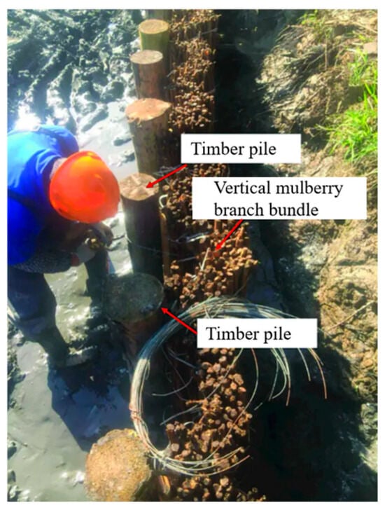
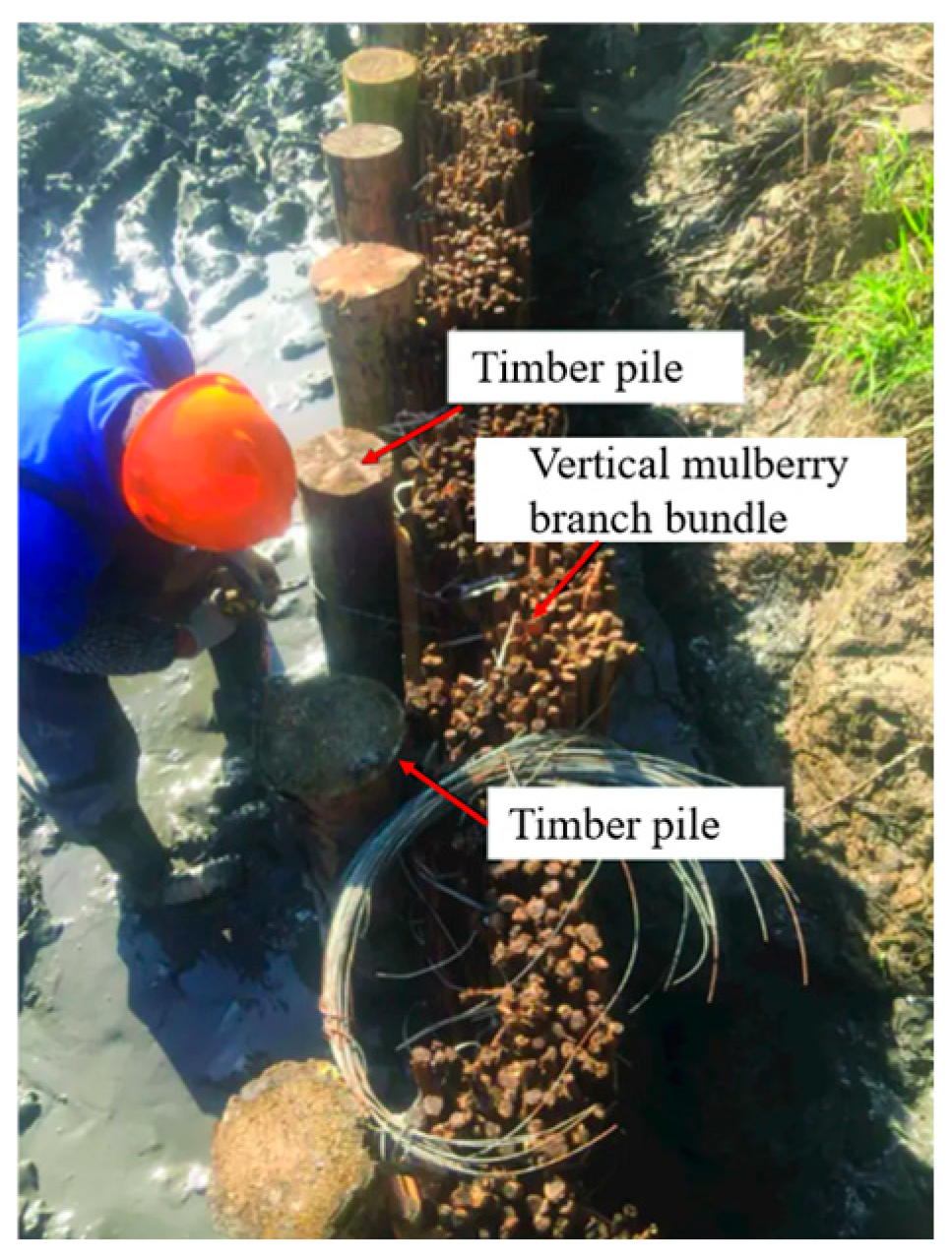
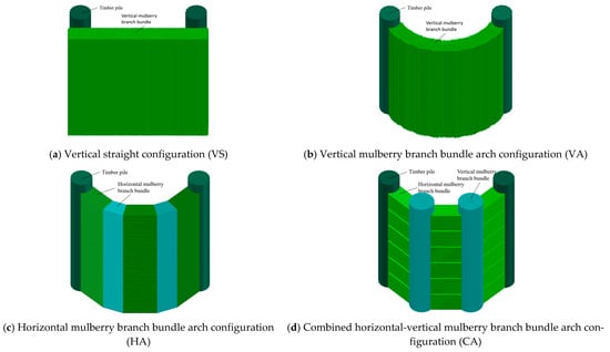
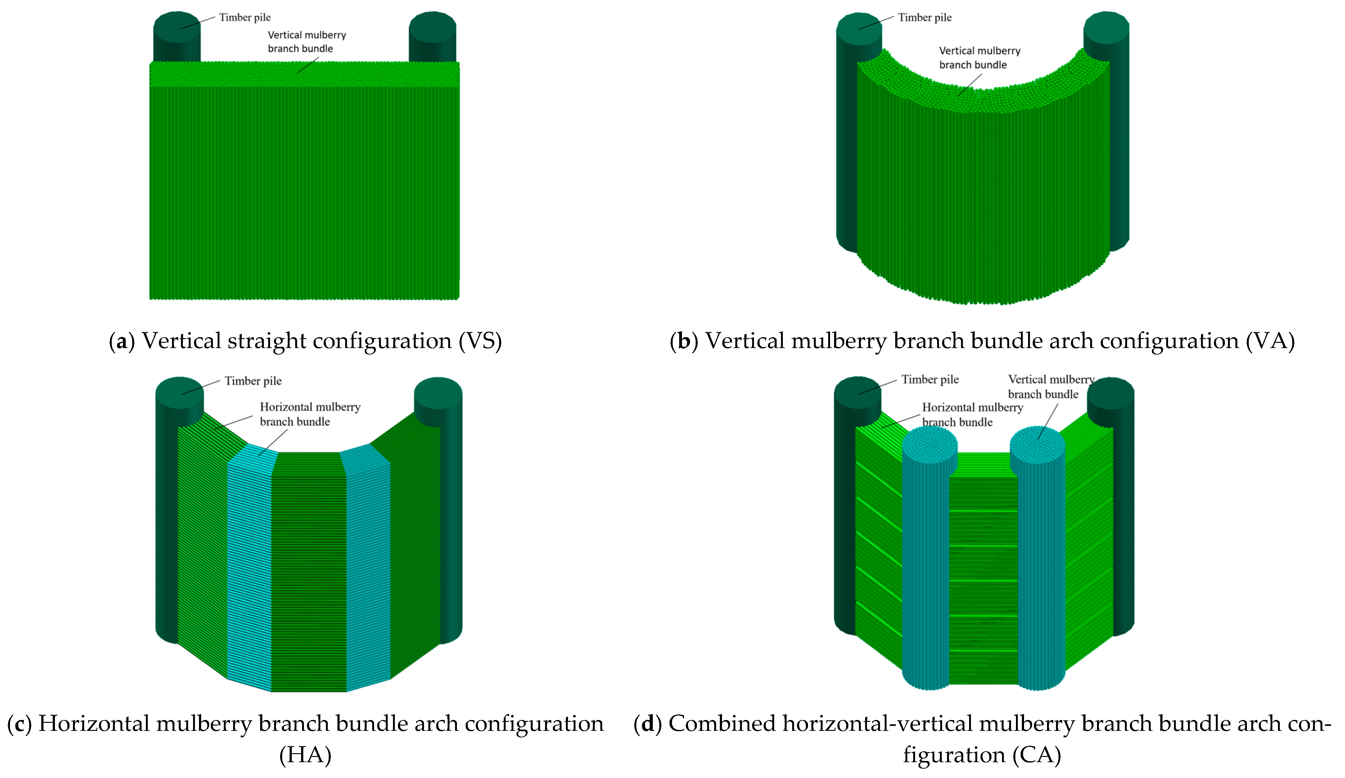
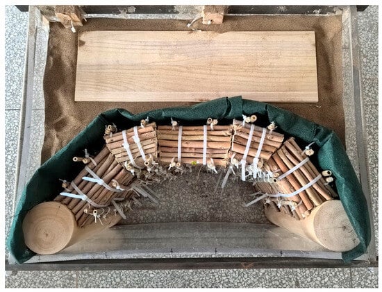
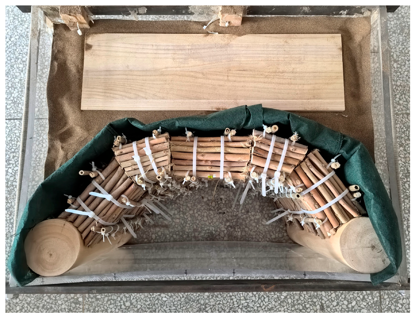
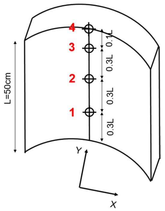
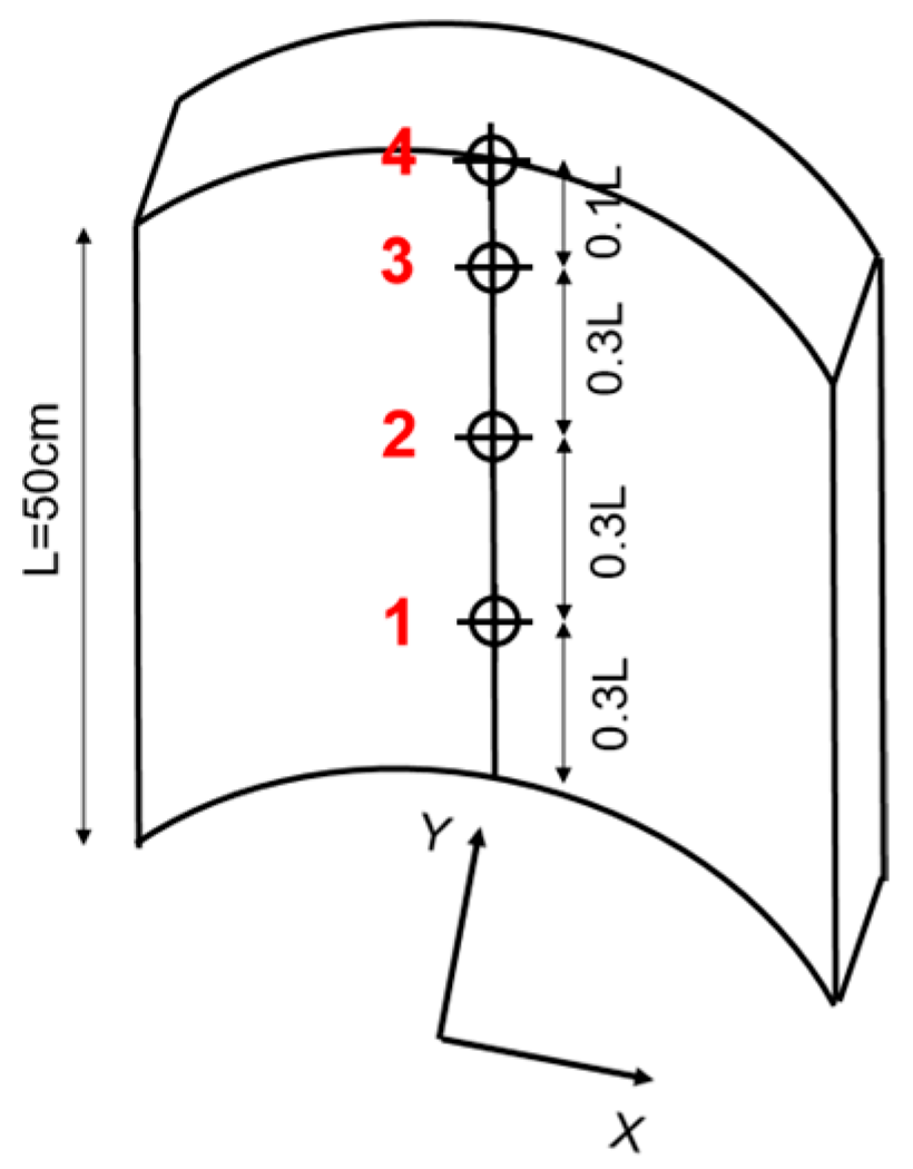
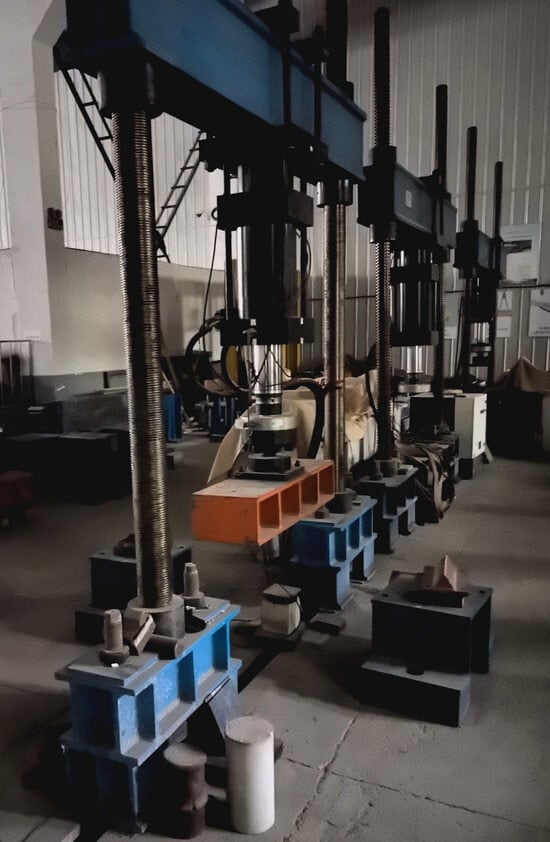
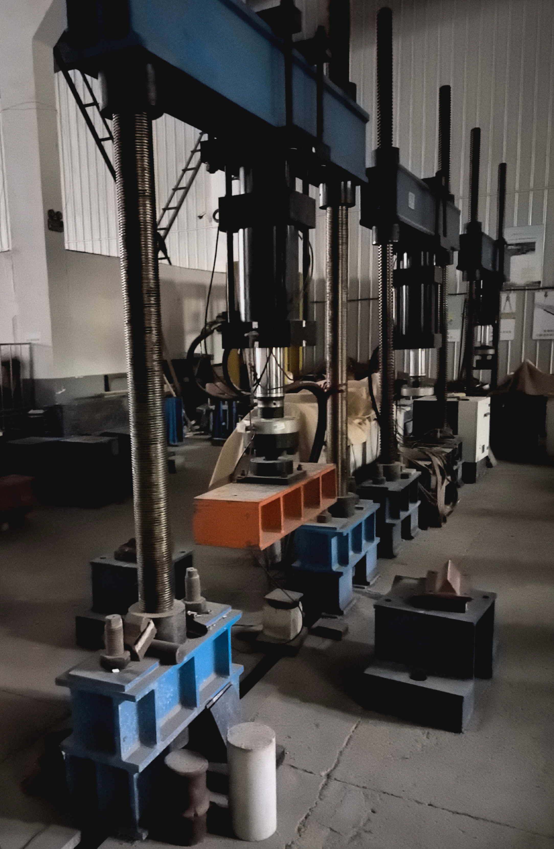
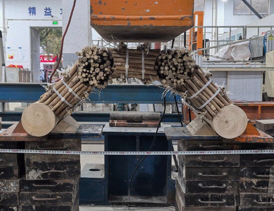
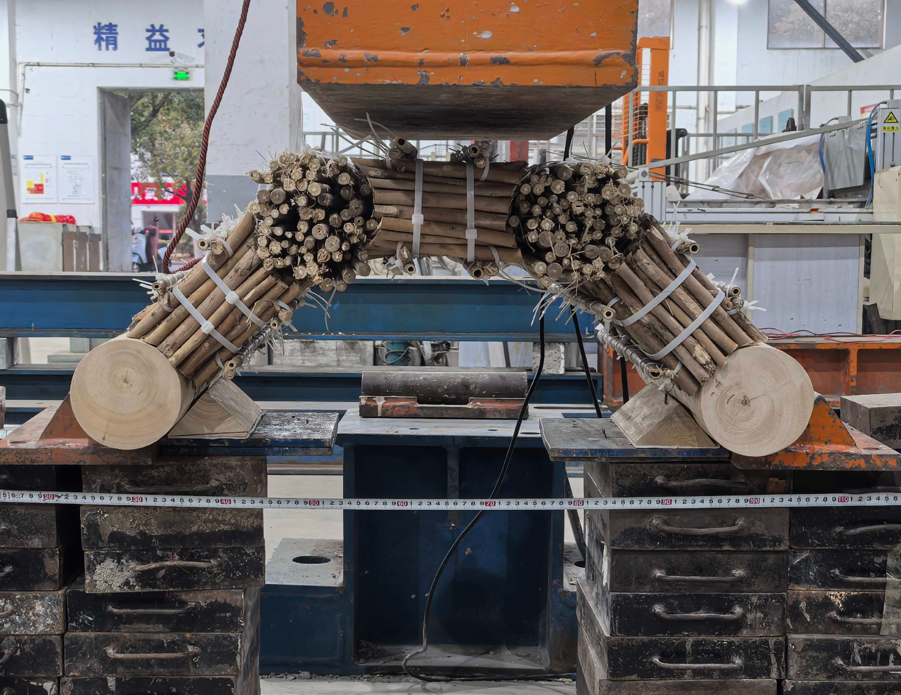
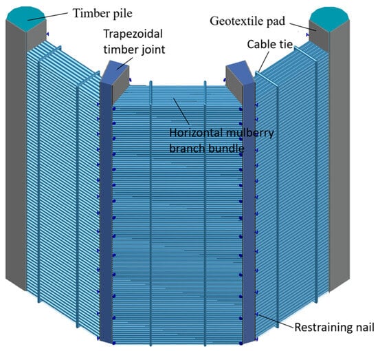
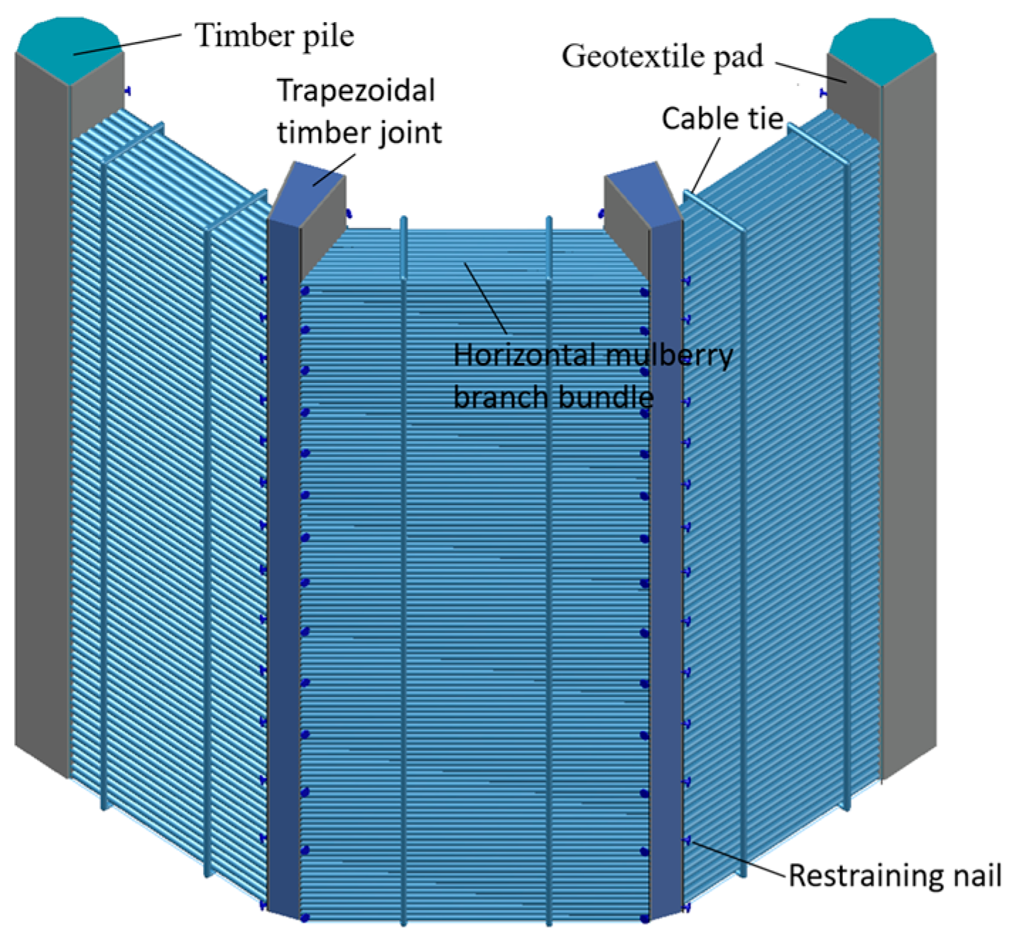
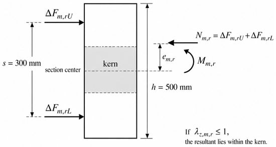
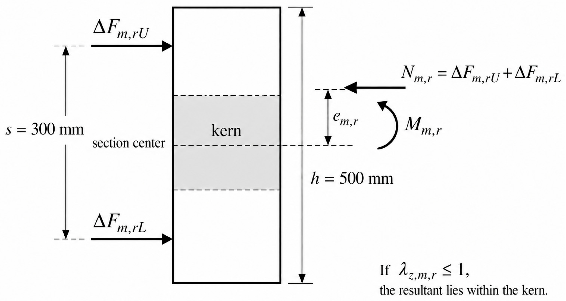
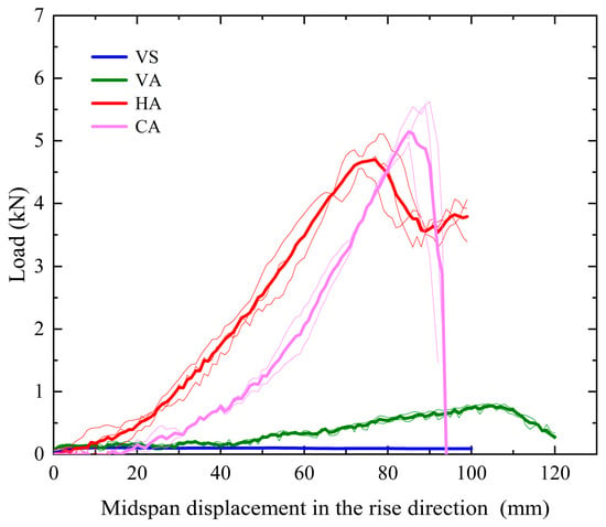
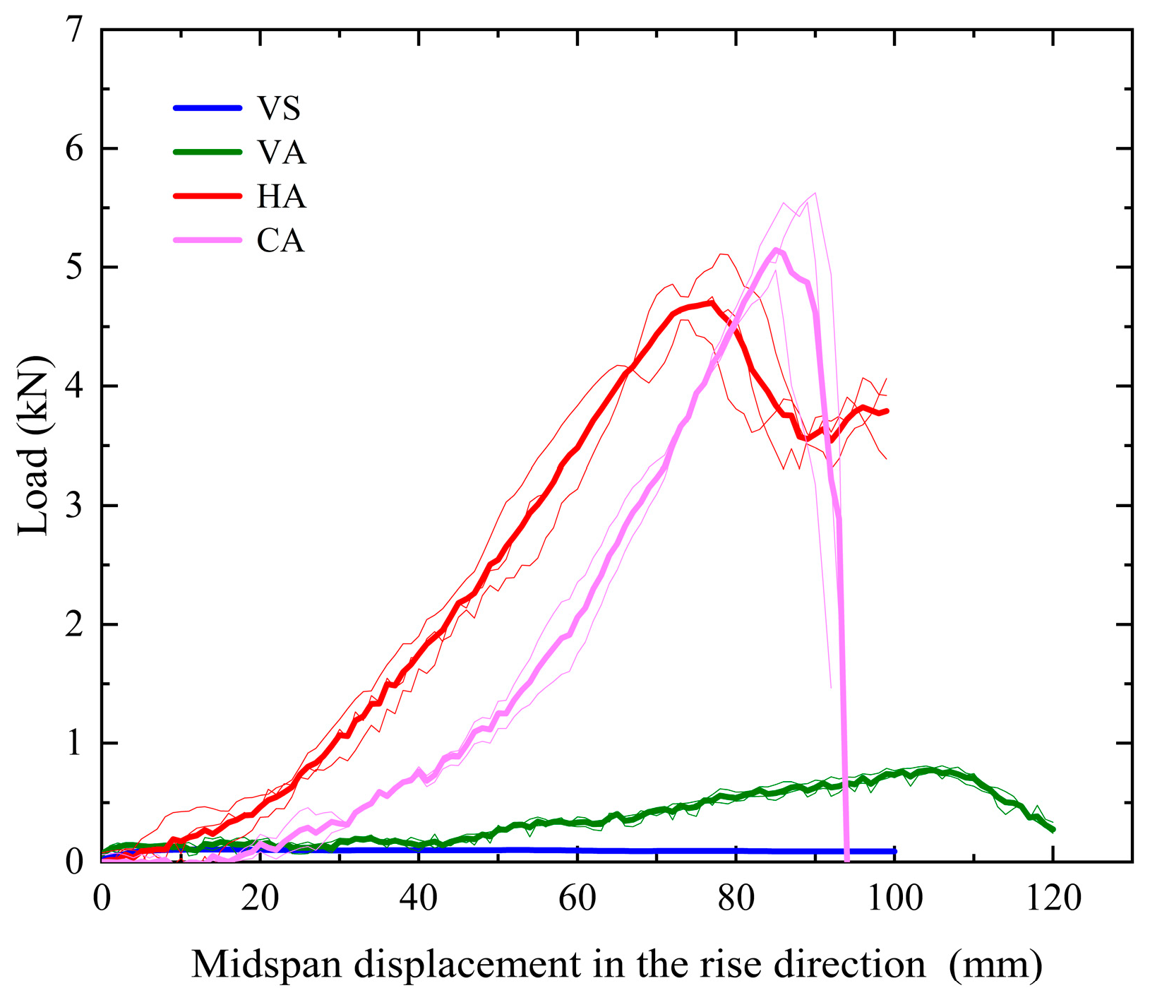
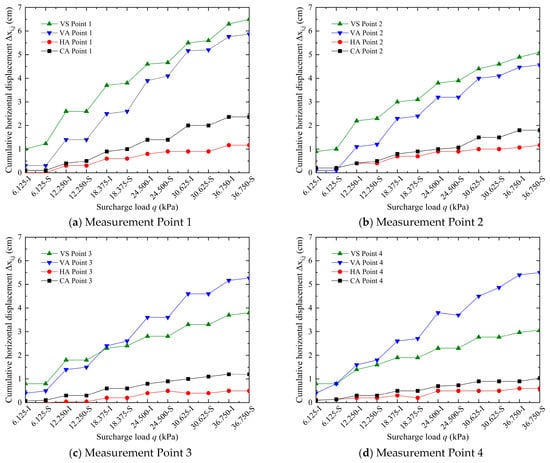
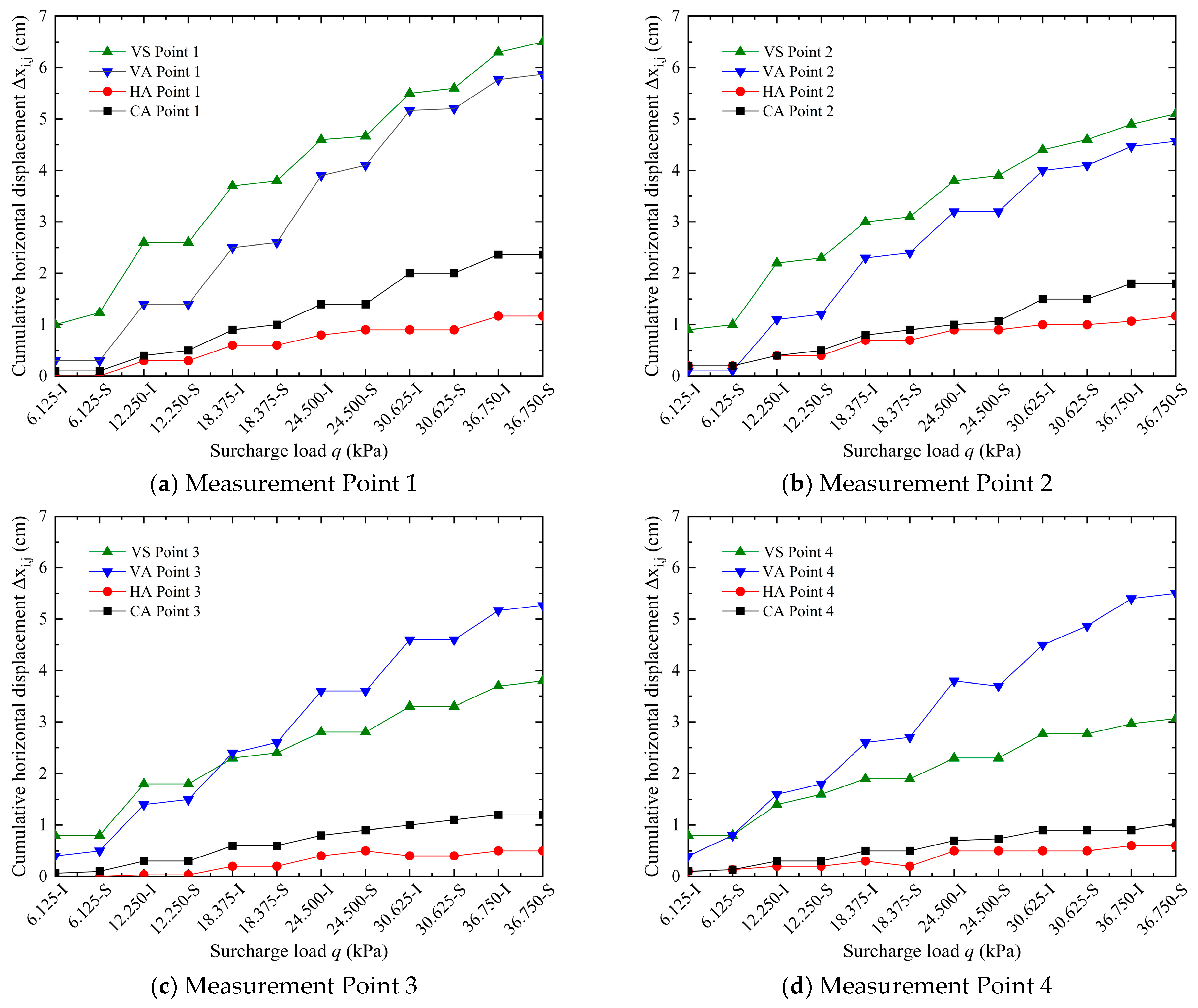
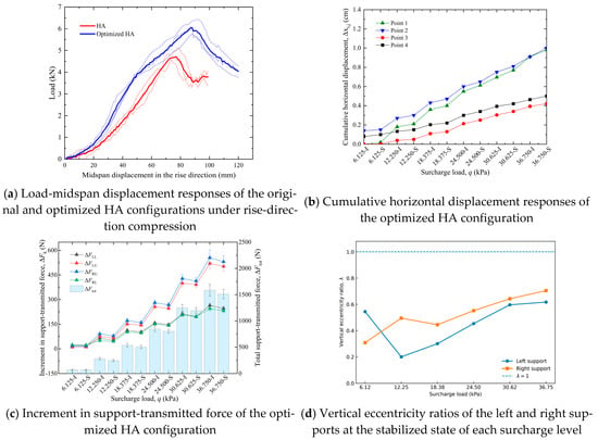
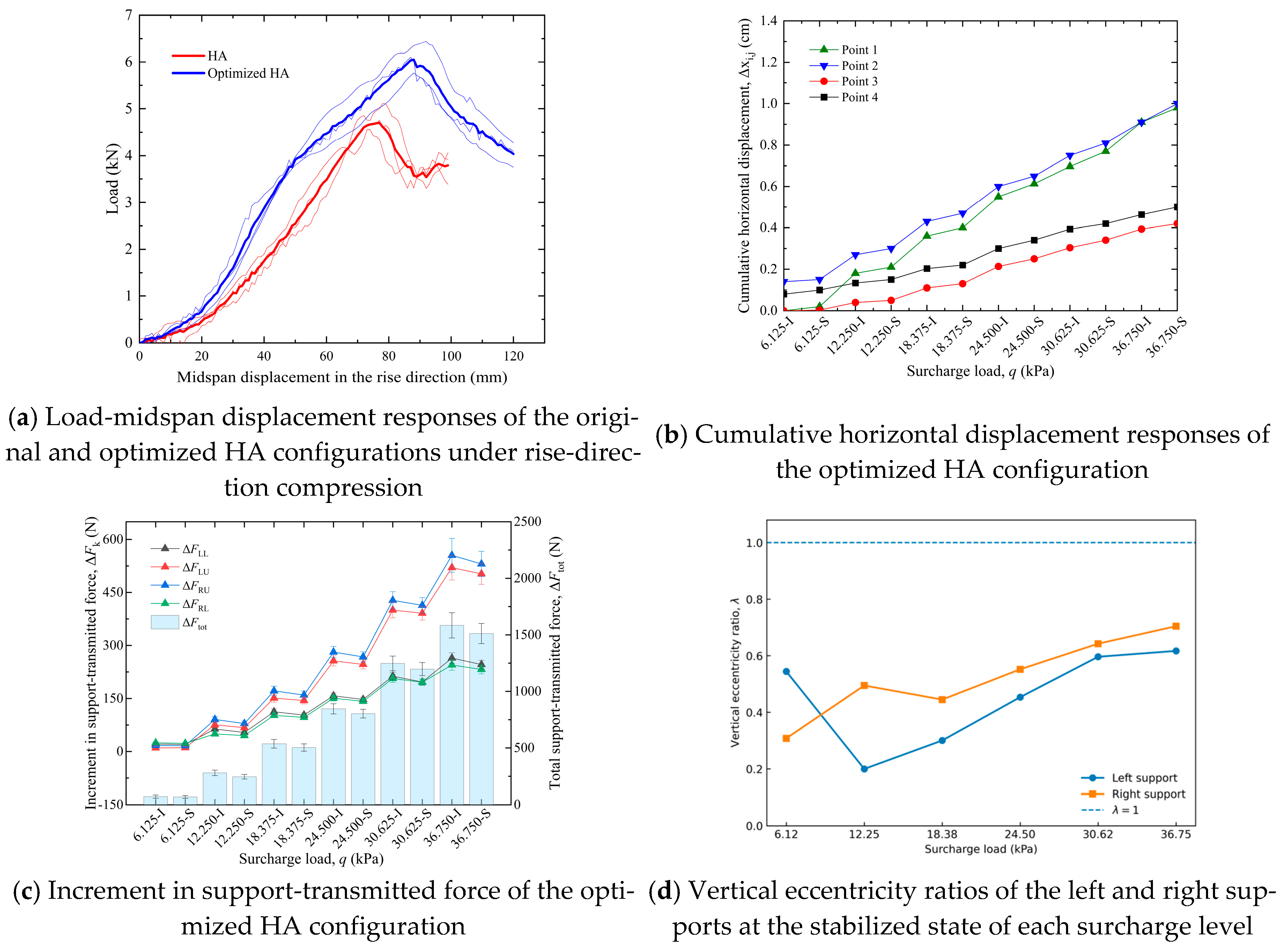
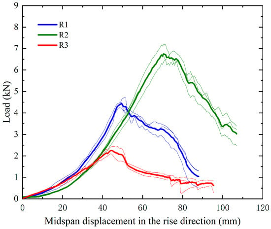
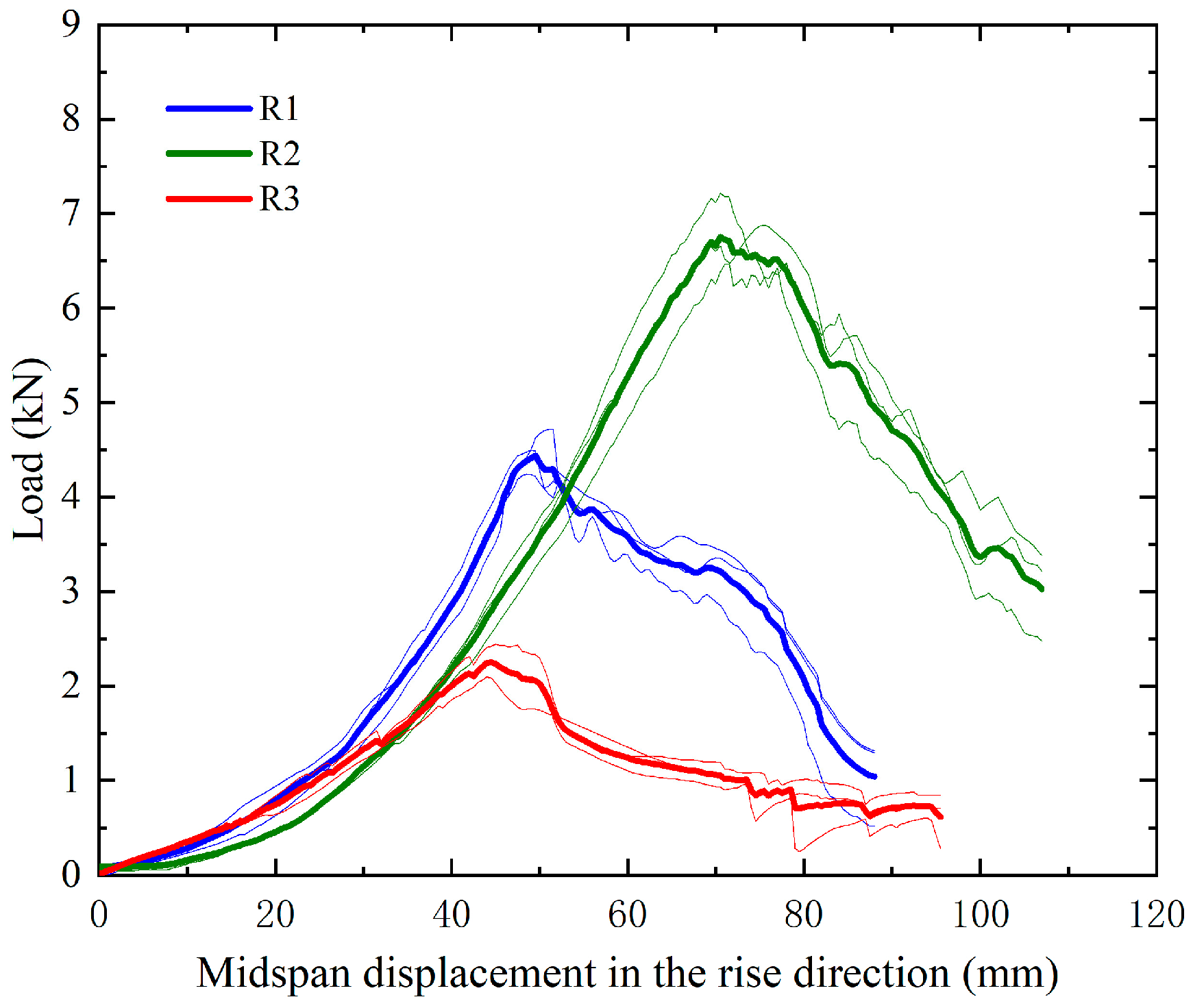
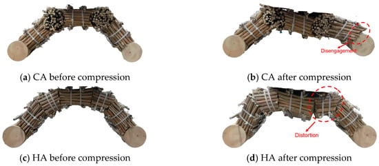
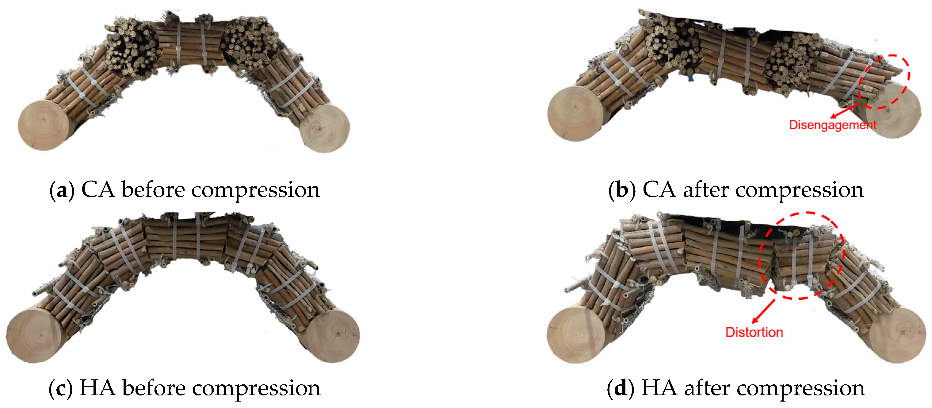

Disclaimer/Publisher’s Note: The statements, opinions and data contained in all publications are solely those of the individual author(s) and contributor(s) and not of MDPI and/or the editor(s). MDPI and/or the editor(s) disclaim responsibility for any injury to people or property resulting from any ideas, methods, instructions or products referred to in the content. |
© 2026 by the authors. Licensee MDPI, Basel, Switzerland. This article is an open access article distributed under the terms and conditions of the Creative Commons Attribution (CC BY) license.