


Abstract
This study develops and experimentally characterizes a prototype sandwich panel intended for load-bearing applications, incorporating continuous corrugated date-palm leaf midrib (DPLM) mats within a polyurethane (PU) foam core between plywood facings. Retaining the midribs’ natural cross-sections preserves their peripheral fiber structure while reducing material processing. Independent DPLM properties were estimated using rectangular and triangular section idealizations. The corresponding mean nominal estimates were 8054.04–24,162.11 MPa for bending modulus, 63.62–254.47 MPa for bending stress, 2568.54–5137.08 MPa for compression modulus and 32.17–64.34 MPa for compression failure stress. The triangular bending stress refers to the apex. The sandwich panels achieved a mean ultimate facing bending strength of 10.21 MPa and an apparent flexural stiffness of 7.90 kN·m2, with a mean gross-section edgewise failure stress of 2.87 MPa and an apparent compression modulus of 308 MPa. Failure involved tensile rupture of the bottom plywood facing under bending and global buckling accompanied by localized core crushing under compression, without visible skin–core delamination. Finite-element models were compared with experimental results, with a bending displacement difference of 13.3% at the maximum sustained load comparison point. Preliminary full-scale analyses identified 4.8 m as the largest analyzed roof-slab span satisfying the adopted numerical checks for load-bearing wall applications (without full-scale buckling verification). For roof or floor applications, increasing the panel thickness from 114 to 220 mm reduced the modeled maximum deflection from 17.5 to 6.4 mm under self-weight plus live load. The 220 mm panel’s live-load deflection was 5.7 mm, below the adopted span/360 limit of 6.78 mm. Guarded-hot-plate measurements on a 135.57 mm thick specimen yielded an effective thermal conductivity of 0.08154 W/(m·K), thermal resistance of 1.6626 m2·K/W and specimen-level thermal transmittance of 0.6015 W/(m2·K). For the nominal 114 mm panel, the estimated specimen-level thermal transmittance was 0.7153 W/(m2·K), exceeding the SBC 601 nonresidential Zone 1 wall comparison value. Following surface treatment, the tested 60 mm thick plywood-faced specimens achieved Euroclass E in single-flame ignitability testing, with no ignition, flame spread or flaming droplets observed. The findings support the potential of minimally processed corrugated DPLM mats in multifunctional sandwich panels. Further full-scale structural validation, manufacturing optimization, creep, vibration and durability assessment, thermal improvement and assembly level fire assessment are required before broader building application.
1. Introduction
The construction industry is undergoing a rapid transition toward materials with lower environmental impacts in response to increasing concerns regarding resource depletion, waste generation, and the carbon emissions associated with conventional building materials. Bio-based construction materials derived from agricultural residues provide a promising alternative because they can convert underutilized waste into value-added products, support regional material supply chains and reduce dependence on virgin resources [1].
Structural sandwich panels offer a high strength-to-weight ratio, structural efficiency, multifunctionality and suitability for prefabricated construction systems. Conventional structural sandwich panels consist of high-strength facings bonded to a lightweight core made of polymeric foam, honeycomb structures or corrugated sheets. Their performance depends on the combined behavior of the facings and core. The facings primarily resist tensile and compressive bending stresses, while the core transfers shear loads, stabilizes the facings against buckling, and can provide thermal insulation [2]. The structural efficiency of sandwich panels can be further increased by integrating corrugated core geometries that improve load transfer and performance under bending, compression, and shear while maintaining a low structural weight [3]. Despite these advantages, many conventional sandwich systems depend on materials associated with high energy consumption, production costs, and environmental impacts, motivating the investigation of renewable alternatives [4].
Natural fibers and agricultural by-products have consequently been investigated as lower-impact alternatives capable of providing competitive mechanical performance [5]. Date-palm biomass is particularly relevant in arid and semi-arid regions because of its regional abundance and the large quantity of residues generated through annual pruning. Approximately 100 million date-palm trees are cultivated worldwide, around 62 million of which are located in the Middle East and North Africa. Reported estimates indicate that each tree can generate approximately 20–40 kg of waste annually, including fronds, midribs, petioles, fibers and other by-products [1]. These residues have attracted research attention because of their mechanical characteristics, thermal performance and low raw-material cost, which offer opportunities for developing bio-based structural and non-structural panels.
Recent studies have explored the use of date-palm by-products in sandwich panels, thermal insulation, acoustic panels and other building applications. However, many existing date-palm sandwich panels require the natural material to be processed into fibers, particles, fabrics, strips or engineered wood. Consequently, their structural performance depends substantially on resin systems and adhesive bonding rather than on the natural mechanical performance of the original date-palm member [6]. Although these approaches demonstrate the technical potential of date-palm residues, extensive processing can increase manufacturing complexity and make bond quality a major factor governing panel performance.
Date-palm leaf midribs (DPLMs) provide a different opportunity because of their unique natural structure, which consists of a dense peripheral layer of fiber bundles surrounding a lightweight inner core. This natural configuration contributes to their bending resistance, flexibility, and potential for structural applications. Retaining the natural geometry of the midribs can preserve mechanical advantages that may be reduced when the material is fragmented into fibers or particles. DPLMs have also been traditionally used in roofing, flooring, and wall elements, demonstrating their potential as lightweight structural members under appropriate loading conditions [7,8].
Building on these characteristics, this study proposes a prototype sandwich panel intended for load-bearing applications, consisting of continuous corrugated DPLM mats embedded within a polyurethane foam core and enclosed by plywood facings. Unlike other date-palm sandwich panels, the proposed system minimizes the processing of the natural material and maintains the mechanical advantages of continuous DPLM members. The corrugated arrangement is intended to enhance the structural contribution of the mat, while the expanding PU foam fills the surrounding cavities, supports and stabilizes the DPLM reinforcement, bonds the core to the facings and provides thermal insulation.
The study characterizes the mechanical properties of independent DPLM specimens and evaluates the developed sandwich panel under bending and edgewise compression. The finite-element models were compared with the experimental results and were subsequently used to examine the potential performance of full-scale wall, floor and roof panels. The thermal performance and reaction-to-fire behavior of the developed panel are also evaluated. Beyond introducing a new structural system, the study examines the technical potential of utilizing agricultural residues in prefabricated panels through limited DPLM processing and combined structural and thermal functions.
2. Literature Review and Research Gap
2.1. Date-Palm Residues and DPLM as Construction Materials
Among the agricultural residues previously investigated for developing sandwich panels are date-palm pruning residues. The renewability, regional availability and versatility of these by-products have encouraged multiple trials to utilize them in construction materials, compensate for the shortage of conventional wood in date-producing regions and benefit from their mechanical and thermal properties [1].
Date-palm leaf midribs (DPLMs) have a natural structure consisting of a dense peripheral region rich in vascular fiber bundles surrounding a lighter inner region. This peripheral region acts as a natural belt that contains the fiber bundles along the midrib and contributes to its longitudinal strength, bending resistance, and flexibility. Accordingly, retaining the natural cross-section and continuity of the midrib may preserve structural characteristics that can be reduced when the material is converted into short fibers, particles or thin strips [7,8].
The potential of the constituent fibers has also been demonstrated experimentally. Alabdali et al. [9] extracted continuous fibers from DPLM using a hydrothermal process with microwave heating. The individual fibers achieved a mean modulus of 17.1 ± 1.5 GPa and a tensile strength of 333 ± 27.4 MPa. When aligned in an epoxy matrix, the resulting composites achieved moduli of 1.72–9.52 GPa and tensile strengths of 16.9–43.8 MPa, depending on the fiber volume fraction. These results demonstrate the mechanical potential of DPLM fibers, although they relate to extracted fibers and resin-based composites rather than intact midribs or complete structural panels. The mechanical performance of date-palm petiole wood has also been found to vary with fiber orientation, cultivar, and growing conditions [10].
DPLMs have a long technical heritage in furniture, crates, coops, light huts, roof sheathing and wall screens. DPLM mats, locally known as seddas, are traditionally produced by binding midribs together using ropes or steel wires until a mat measuring approximately 4.00 × 2.00 m is completed. The mats are commonly stored and sold in rolls. In traditional mud-brick houses in rural Egypt, they were placed over beams made from date-palm trunks to form structural layers in roofs and subfloors. This traditional use demonstrates the potential for assembling continuous DPLM into large prefabricated units, although it does not provide standardized mechanical properties or design values for modern load-bearing applications [7,8].
2.2. Date-Palm-Based Panels
Haseli et al. [11] developed lightweight sandwich panels consisting of blockboard and battenboard cores made from waste date-palm trunks and thin medium-density-fiberboard facings. Different core orientations and polyurethane- and polyvinyl-acetate-based adhesives were examined. The mechanical properties were generally better when the trunk fibers were oriented longitudinally, while the polyurethane-based adhesive improved bonding and the distribution of bending stresses. A thermal conductivity of approximately 0.14 W/(m·K) was reported, indicating moderate thermal-insulation performance suitable for interior panel applications. However, the system used processed trunk components, manufactured facings, and adhesive connections rather than continuous DPLMs.
Djemai et al. [12] developed sandwich specimens with rachis-fiber/epoxy skins and cores made from raw petiole wood, petiole agglomerates of different particle sizes, or agglomerated cork. Petiole agglomerates with particle sizes of 0–1 mm achieved the highest overall stiffness among the tested configurations. Delamination tests also indicated good resistance at the skin–core interface. Nevertheless, the manufacturing process involved fiber extraction, epoxy skins, grinding and sieving of the petiole, white-glue agglomeration, and controlled curing.
Benzidane et al. [6] used untreated short rachis fibers in epoxy skins and untreated petiole wood as the core. A fiber mass fraction of 15% was selected to improve the stiffness of the skins. Core orientation had an important influence on failure, and transverse orientation prevented the core-shear failure observed in the other orientations. The dominant failure modes were bottom-skin failure and core shear. Although the study demonstrated an efficient method of valorizing date-palm waste, the resulting panels were proposed for non-structural applications and their performance remained dependent on epoxy skins and discrete petiole-core pieces.
Darwish and Moustafa [7] developed ModPalma, a full-size stud-frame wall panel made entirely from DPLM without a supporting timber frame. The midribs were retained in a relatively natural form and assembled using techniques derived from traditional DPLM handicrafts. A full-size prototype demonstrated the constructional coherence and workability of the design, while finite-element analysis indicated that it was safe under loads exceeding the referenced allowable axial and transverse loads of standard structural insulated panels. Nevertheless, structural capacity was assessed numerically rather than through full-panel mechanical testing, and fabrication remained dependent on the precision and experience of the craftsman. Their subsequent panel development was assessed through finite-element analysis under self-weight and wind loads and was proposed mainly for cladding, partitions and light non-load-bearing construction [8].
Ahmed and Sikora [13] investigated three-, five- and seven-layer cross-laminated panels made from 2 mm thick DPLM strips bonded with polyurethane adhesive under clamping pressure. The three-layer specimens achieved a mean bending strength of approximately 2.8 MPa, while delamination was among the principal failure mechanisms. The authors concluded that DPLM cross-laminated panels in the tested configuration might not be viable as a structural material. These results demonstrate that cutting DPLM into thin strips and relying on adhesive bonding does not necessarily exploit the full strength of the original midrib.
Djoudi et al. [14] investigated sandwich structures with rachis-fiber/epoxy skins and cores made from raw petiole wood, petiole particles, or agglomerated cork. The core type and particle size affected both bending and thermal performance, and skin–core delamination was not observed after bending failure. However, the specimens remained small-scale resin-based composites made from processed fibers and raw or agglomerated petiole components.
The main configurations, contributions, and limitations of the reviewed date-palm-based panels are summarized in Table 1.
Table 1.
Selected date-palm-based panels and limitations relevant to the present study.
DPLM have also been investigated in wood–cement composites [15]. However, this application does not address the development of a multifunctional load-bearing sandwich panel. In addition, although several studies describe date-palm residues as inexpensive or freely available agricultural by-products, they do not provide quantitative comparisons of material, manufacturing or installation costs. Therefore, the economic advantage remains a reasonable potential benefit rather than a fully demonstrated outcome.
2.3. Corrugated-Core and Foam-Filled Structural Panels
Corrugation can improve the structural efficiency of sandwich panels by increasing their effective depth and creating inclined load-transfer paths between the facings. However, performance depends on the corrugation geometry, web inclination, bonding area and quality of the core-facing interface. In a numerical comparison of five corrugated-core geometries made with the same material, size and weight, Rong et al. [16] found that the trapezoidal configuration provided the best planar-compression performance and favorable low-energy impact behavior. Its performance was attributed to its relatively large bonding areas and high out-of-plane stiffness. This comparison demonstrates the importance of corrugation geometry, bonding area and out-of-plane stiffness, but it does not establish that the approximately sinusoidal corrugation adopted in the present prototype is optimal.
Embedding corrugated members within foam may stabilize the corrugated webs, restrain local buckling and connect the corrugation to the facings. Han et al. [17] analytically and numerically investigated foam-reinforced corrugated sandwich beams under transverse bending and demonstrated that foam filling could improve stiffness, collapse strength and weight efficiency compared with unfilled corrugations. The improvement depended on the properties of the foam, corrugation geometry and governing failure mode. Foam filling may also provide thermal insulation, although its reaction-to-fire behavior must be assessed separately and cannot be inferred from its structural or thermal performance.
A close construction-related comparison was provided by Mohammadabadi et al. [18], who developed full-size 1.2 × 2.4 m sandwich panels with one- and two-layer biaxially corrugated wood-strand cores. The corrugated cavities were filled with closed-cell foam to improve thermal performance. The two-layer wall panels achieved higher ultimate bending and axial-compression capacities than the referenced structural insulated panels and timber-stud walls. Their normalized thermal resistance was also higher than that of common wood-based panels, although specialized commercial insulation materials provided better thermal performance. This work demonstrates the multifunctional potential of combining a bio-based corrugated core with foam. Nevertheless, its core was manufactured from processed wood strands and resin rather than continuous DPLM retained in its natural cross-section. Research on vernacular houses in Saudi Arabia has also highlighted the importance of evaluating locally adapted construction in relation to indoor thermal performance [19].
2.4. Research Gap, Aim and Significance
The reviewed literature demonstrates that date-palm residues can be used in sandwich panels, thermal cladding and other construction materials. Nevertheless, three connected gaps remain. First, most date-palm panels process the residues into fibers, particles, strips, blocks or engineered wood components, making their performance strongly dependent on resin matrices and adhesive bonding. This processing can remove the dense peripheral region and structural continuity that contribute to the natural strength of DPLM [6,11,12,13,14].
Second, the studies that retained DPLM in a relatively natural form depended heavily on manual precision and traditional craftsmanship, while their structural assessment relied mainly on finite-element analysis [7,8]. Consequently, comprehensive experimental evidence combining panel-specimen bending and edgewise-compression testing with thermal and reaction-to-fire assessment remains limited.
Third, to the authors’ knowledge, no published study has combined continuous, minimally processed DPLM mats, retained in their natural cross-section and arranged in a corrugated geometry, with a foam core and structural facings, followed by experimental material characterization, panel-specimen structural testing, finite-element model comparison, modeled full-scale application assessment, thermal testing and reaction-to-fire testing.
Accordingly, this study aims to develop and experimentally characterize a prototype sandwich panel intended for load-bearing applications, consisting of continuous corrugated DPLM mats embedded within a polyurethane foam core and enclosed by plywood facings. The foam supports and stabilizes the corrugated DPLM mat, bonds the core to the plywood facings, and provides thermal insulation, while the mat serves as continuous reinforcement within the core.
The specific objectives are to
- Characterize the bending and compression properties of independent DPLM specimens;
- Determine the flexural and edgewise-compression performance and failure modes of the developed sandwich panel;
- Evaluate finite-element models against the experimental results and assess full-scale wall, floor and roof applications;
- Measure the effective thermal performance of the panel;
- Assess its reaction-to-fire performance using a single-flame ignitability test.
The significance of the study lies in merging the reduced processing and natural structural strength of DPLM with the structural and thermal functions of a foam sandwich panel. The proposed configuration preserves the continuous midribs and their dense peripheral region, uses the traditional sedda as a ready-made reinforcement mat and arranges it in a corrugated form to enhance load transfer. At the same time, embedding the mat in foam has the potential to provide a more repeatable prefabrication approach than a completely handcrafted corrugated DPLM-reinforced sandwich panel. Thus, this study is an exploratory investigation of the potential of the concept of a corrugated DPLM-reinforced sandwich panel in three crucial aspects—structural integrity, thermal performance, and reaction to fire—as an introduction to more in-depth analysis in each aspect in order to optimize the construction method and geometry of the panel in future research.
3. Materials and Methods
3.1. Panel Design and Modeling
3.1.1. Panel Elements and Digital Modeling Technique
The prototype load-bearing sandwich panel was digitally modeled as a multifunctional, prefabrication-ready composite unit. The panel incorporates continuous, corrugated date-palm leaf midrib (DPLM) mats embedded within a self-expanding polyurethane (PU) foam core and enclosed by structural plywood facings and perimeter framing.
To accurately evaluate the geometry, layer interactions, and exact material volumes, a 3D Building Information Modeling (BIM) model was constructed in Autodesk Revit (Figure 1). The full-scale panel had overall dimensions of 2476 × 1220 × 114 mm. The two plywood facings and the longitudinal side members were 2440 mm long, corresponding to the standard plywood-sheet length. Two 18 mm thick, full-depth plywood end caps extended the assembled length to 2476 mm.
Figure 1.
The BIM Revit model of the panel.
The panel geometry was modeled within Revit using in-place generic models with solid extrusions of 2D profiles (panel cross-sections). Each geometry element’s material was created and assigned inside the generic model material browser.
3.1.2. Panel Layers
The layers and structural enclosure modeled in Revit include:
- •
- Plywood Facings and Perimeter Enclosure: The top and bottom plywood facings each measured 18 × 2440 × 1220 mm. The core was bounded laterally by two longitudinal plywood side members measuring 18 × 78 × 2440 mm. Two full-depth plywood end caps, each measuring 18 × 114 × 1220 mm, enclosed the panel ends and increased its overall length to 2476 mm. The cumulative modeled volume of all plywood components was 0.119 m3.
- •
- Corrugated DPLM Reinforcement Core: The DPLMs modeled in Revit retain their irregular triangular cross-sections. The cross-sections were traced from actual-size DPLM samples used for the testing. The corrugated date-palm leaf midrib (DPLM) mats’ cross-sections are modeled with a corrugation wave having a wave depth of 63 mm within the 78 mm core depth. They are arranged longitudinally with a centerline pitch of 75 mm (Figure 2). The wave depth and pitch dimensions were determined based on a literature review. This core yields an average volume of 0.048 m3.Figure 2. Cross-section and three-dimensional Revit model of the panel.
- •
- Polyurethane (PU) Foam: Modeled to completely penetrate the inter-midrib spacing and cover the corrugated mat over the clear internal cavity (2440 mm × 1184 mm × 78 mm). The net modeled volume of the PU foam fill—after subtracting the embedded DPLM core volume from the gross cavity volume—is 0.177 m3.
The digital BIM Revit model provided the geometric parameters for prefabrication tolerances and served as the basis for digital analysis and material assignment in the subsequent finite-element analysis (FEA) models.
3.2. Material Preparation and Panel Fabrication
3.2.1. Material Preparation
The DPLMs were obtained in Madinah, Saudi Arabia, from Rothana and Ajwa date-palm cultivars. Figure 3 shows a representative Rothana date palm. The material was purchased as a ready-made 2.00 × 4.00 m sedda, a traditional DPLM mat that had been sun-dried, bound with six steel wires, and stored in rolled form after harvesting in spring 2025 (Figure 4). The moisture content measured before panel fabrication was approximately 12%. This value characterizes the DPLMs before fabrication. The moisture condition at structural testing is addressed separately in Section 3.3.
Figure 3.
Rothana date palm in Madinah, Saudi Arabia.
Figure 4.
DPLM sedda before cutting.
Before panel fabrication, a 2.00 × 2.50 m section was cut from the sedda and treated with an aqueous buffered borate solution. The solution was prepared by first dissolving 113 g of borax (Na2B4O7·10H2O), followed by 100 g of boric acid (H3BO3), in 2.0 L of water at approximately 62–65 °C, with continuous stirring until the solution became clear. Approximately 1.5 L of the solution was spray-applied to both faces of the 2.00 × 2.50 m DPLM mat, corresponding to a total nominal treated area of 10 m2 (Figure 5). The DPLM specimens used for the independent bending and compression tests were cut from the remaining area of the sedda (Figure 6).
Figure 5.
Application of the buffered borate solution to the DPLM mat.
Figure 6.
Cutting independent DPLM specimens for the bending and compression tests.
Self-expanding D9000 aerosol polyurethane (PU) foam (Dermax Chemical Co., Ltd., Al Kharj Industrial City, Saudi Arabia) was used to fill the space between the DPLM mat and the plywood facings and to penetrate the gaps between the individual DPLMs. According to the manufacturer, this single-component, moisture-curing foam has a volumetric expansion of up to 78 times its dispensed volume, making it suitable for filling gaps, joints, and cavities [20]. This expansion enabled the foam to fill the internal voids and form a continuous core around the corrugated DPLM mat. The manufacturer-reported properties of the PU foam are presented in Table 2. The mechanical properties of the foam were obtained from the available literature [21].
Table 2.
Manufacturer-reported properties of the PU foam.
The two facings were made from nominally 18 mm thick, nine-ply Indonesian Falcata-core plywood panels. The product characteristics were obtained from the supplier’s technical data sheet [22]. The bending strengths and moduli of elasticity adopted for finite-element modeling were obtained from the technical data sheet of a comparable 18 mm thick Albizzia/Falcata plywood product [23]. The product characteristics and adopted mechanical properties are summarized in Table 3.
Table 3.
Product characteristics and adopted mechanical properties of the plywood facings.
3.2.2. Panel Fabrication
The principal steps followed in fabricating the panel are presented in Figure 7, Figure 8, Figure 9, Figure 10, Figure 11, Figure 12 and Figure 13. The first step was to create the corrugation. The DPLM mat was relatively stiff because the midribs were dry, tightly bound with steel wires, and had an average cross-sectional width of approximately 17 mm. Therefore, the binding wires were slightly loosened to create sufficient spacing between adjacent DPLMs, allowing the PU foam to penetrate the gaps in the mat and form a cohesive foam core.
Figure 7.
Weaving the plastic tie rope through the DPLM mat to create the corrugation.
Figure 8.
Roughening the inner surface of a plywood facing.
Figure 9.
Wooden battens used to raise and position the DPLM mat.
Figure 10.
Application of PU foam beneath and between the DPLMs.
Figure 11.
Weights placed above the top facing to control foam-induced swelling.
Figure 12.
Panel after sealing the plywood facings.
Figure 13.
Cross-section of the completed panel showing the corrugated DPLM mat and the solidified PU foam penetrating the mat and forming a flush connection with the plywood facings.
The mat was then lightly sprayed with water to increase its flexibility and allow it to take the corrugated form without cracking. A plastic tie rope was woven through the mat around every group of three DPLMs. This process was repeated at four positions along the length of the mat, producing an approximately sinusoidal corrugation (Figure 7). Meanwhile, the inner surfaces of the plywood facings were roughened to improve their bonding with the PU foam (Figure 8). After the assembly surface had been secured and checked for level, the corrugated mat was transferred onto the bottom plywood facing. Three sides of the perimeter frame were then added and fixed to the bottom facing using nails and glue. Wooden battens were placed beneath the mat to raise it (Figure 9).
PU foam was sprayed beneath the mat and into the gaps between the DPLMs (Figure 10). As the foam expanded, the top plywood facing was added and secured to the frame using nails and glue. One short side of the panel was left open to allow additional PU foam to be injected into the core. Cement bags weighing 50 kg were placed on the top facing to control swelling caused by the expanding foam and to maintain a level panel surface (Figure 11). The panel was left undisturbed for three days to allow the foam to complete its expansion and curing. Excess foam was then removed, and the final side of the frame was added and fixed to seal the panel (Figure 12). A total of twenty-two 750 mL cans of PU foam were used to fabricate the panel. Finally, the panel was cut to the dimensions required for the test specimens. Figure 13 shows a cross-section of the completed panel, in which the solidified PU foam penetrated the gaps within the corrugated DPLM mat and remained in continuous contact with the plywood facings.
Using modeled volumes and adopted densities, estimated masses were 23.0 kg of DPLM, 39.4 kg of plywood and 3.9 kg of cured PU foam, totaling 66.3 kg, with a DPLM share of 34.7%. Plywood contributed additional wood biomass. The foam mass was estimated using the manufacturer-reported density of 22 kg/m3 and may be underestimated under confined expansion. An adopted DPLM density of 480 kg/m3 was used for the material inventory. Steel wires, assembly adhesives, fasteners and treatment masses were not separately quantified. Fabrication used twenty-two 750 mL PU aerosol cans. Further environmental assessment should include all material inputs, manufacturing processes and aerosol packaging.
3.3. Structural Testing
The structural specimens were prepared as described in Section 3.2, including a three-day foam-curing period for the sandwich panels. The individual DPLM tests used procedures adapted from EN 408 [24]. For sandwich panels, ASTM D7249 [25] and ASTM C364 [26] permit testing as prepared when no pre-test conditioning environment is specified. Moisture content at structural testing was not separately measured for either specimen group and is reported as unknown; controlled conditioning conditions are not documented in the available laboratory records.
3.3.1. Testing of Independent DPLM Specimens
The panel was designed so that most stresses generated under bending and compression act parallel to the grain of the DPLM. This principle was important because the compressive strength and modulus of elasticity parallel to the grain are superior to those perpendicular to the grain [7,8]. The independent DPLM specimens were tested to characterize their mechanical properties under bending and compression parallel to the grain. These results were used for material characterization and comparison with previously reported natural materials. The nominal properties calculated were the global modulus of elasticity and strength in bending parallel to the grain, and the modulus of elasticity and strength in compression parallel to the grain. Because the DPLM specimens retained their natural irregular triangular cross-sections with rounded corners, the testing and calculation procedures were adapted from BS EN 408 [24]. The finite-element analysis was informed by the experimentally determined response of the complete sandwich-panel specimens, as described in Section 3.4.
- Modulus of Elasticity in bending parallel to grain
Three DPLM specimens were subjected to four-point bending, as shown in Figure 14. The support span, l, was 360 mm, and the distance between each loading point and the nearest support, a, was 120 mm. After plotting the load–deflection response, the global modulus of elasticity in bending, Em,g (MPa), was calculated using Equation (1). Because the DPLMs retained their natural irregular cross-sections, the measured maximum base width and depth were used to define rectangular and triangular cross-section idealizations for the adapted EN 408 calculations. Results are reported as nominal estimates under these two section assumptions.
where l is the support span (mm), I is the assumed second moment of area (mm4), F2 − F1 is the load increment within the linear portion of the load-deflection curve (N), w2 − w1 is the corresponding displacement increment (mm), and a is the distance from a loading point to the nearest support (mm). The rectangular envelope uses I = bh3/12; the triangular idealization uses I = bh3/36. The same recorded loads, dimensions and displacement increments were used for both calculations.
Figure 14.
Four-point bending test setup for the independent DPLM specimens.
- b.
- Bending Strength
From the same four-point bending test, the nominal extreme-fiber bending stress parallel to the grain, fm, was calculated using Equation (2).
where fm is the nominal extreme-fiber bending stress (MPa), Fmax is the maximum applied load (N), a is the distance between a loading point and the nearest support (mm), and W is the assumed section modulus (mm3). The rectangular idealization uses W = bh2/6. For the triangular idealization with the apex facing upward, Equation (3) gives W = bh2/24 at the apex; the flat-base value is W = bh2/12.
fm = a Fmax/(2W)
- c.
- Modulus of Elasticity in compression parallel to grain
Three specimens were tested in compression parallel to the grain, as shown in Figure 15. The specimen length was approximately six times the smaller cross-sectional dimension. The modulus of elasticity in compression, Ec (MPa), was calculated using Equation (4).
where F2 − F1 is the recorded load increment (N), w2 − w1 is the corresponding deformation increment (mm), l1 is the original specimen length (mm), and A is the assumed cross-sectional area (mm2). The rectangular envelope uses A = bh; the triangular idealization uses A = bh/2.
Figure 15.
Compression test setup for the independent DPLM specimens.
- d.
- Compression Strength
From the same test, the nominal compression failure stress parallel to the grain, fc, was calculated using Equation (5).
where fc is the nominal compression failure stress (MPa), Fmax is the maximum applied load (N), and A is the cross-sectional area (mm2). The tested specimens are shown in Figure 16, and their measured dimensions are presented in Table 4.
fc = Fmax/A
Figure 16.
Independent DPLM specimens used in the bending and compression tests.
Table 4.
Dimensions of the independent DPLM bending and compression specimens.
3.3.2. Testing of Panel Specimens
Six panel specimens were tested in four-point bending, as shown in Figure 17 and Figure 18, using a procedure adapted from ASTM D7249/D7249M-20 [25]. Specimens measured 600 × 75 × 114 mm, with a 78 mm core and two 18 mm plywood facings. The support span, S, was 560 mm and the loading span, L, was 100 mm, giving a distance of 230 mm between each loading point and the nearest support. The specimen width was smaller than the total thickness, and the span-to-thickness ratio was approximately 4.9. These deviations are relevant to the apparent stiffness and possible shear-deformation contribution discussed below.
Figure 17.
Panel specimens prepared for the four-point bending test.
Figure 18.
Four-point bending test setup for the panel specimens.
- Ultimate Bending strength
The ultimate facing bending strength, Fb,u, was calculated using Equation (6).
where Fb,u is the ultimate facing bending strength (MPa), Pmax is the maximum sustained load immediately before facing failure (N), S is the support span (mm), L is the loading span (mm), d is the total panel thickness (mm), c is the core thickness (mm), b is the specimen width (mm), and t is the facing thickness (mm). Isolated terminal machine points occurring after the main failure response were not used as the failure loads.
- b.
- Effective bending modulus
The apparent bending modulus, Eb, was calculated using Equation (7) from the selected increasing branch after the initial load transient and before the extended plateau. Table 5 reports the endpoint pairs used for Equations (7) and (9).
where Eb is the apparent bending modulus (MPa), σ2 − σ1 is the stress increment (MPa), ε2 − ε1 is the corresponding strain increment, and the remaining symbols are as previously defined.
Table 5.
Recorded post-transient endpoint pairs used to calculate apparent panel bending properties.
Equivalent surface strain was calculated from the recorded displacement using Equation (8) for the symmetrical four-point loading geometry. The exported records do not identify the displacement sensor; the calculated modulus and stiffness are therefore reported as apparent values that may include fixture compliance and shear deformation.
where δi is the recorded displacement at the corresponding load level (mm), used as an equivalent beam-deflection input. For the adopted geometry, S = 560 mm, L = 100 mm and a = 230 mm, Equation (8) becomes:
- c.
- Flexural stiffness
The effective flexural stiffness represents the panel’s ability to resist deformation under bending loads. It was calculated using Equation (9).
where DF is the effective flexural stiffness, reported in kN·m2, P2 − P1 is the load increment within the linear portion of the load–deflection curve, and ε2 − ε1 is the corresponding strain increment. The resulting modulus and flexural stiffness represent effective properties of the tested panel configuration.
- d.
- Ultimate edgewise compressive strength
Five panel specimens were tested under edgewise compression, as shown in Figure 19 and Figure 20. The edgewise-compression strength procedure was adapted from ASTM C364/C364M-16(2024) [26], while the stress–strain calculation used to determine the effective compression modulus was adapted from ASTM C365/C365M-22 [27].
Figure 19.
Panel specimens prepared for the edgewise-compression test.
Figure 20.
Edgewise-compression test setup for the panel specimens.
Each specimen was 800 mm high, 240 mm wide, and 114 mm thick. The ultimate edgewise compressive strength, Fc,u, was calculated using Equation (10).
where Fc,u is the facing-based edgewise failure stress (MPa), Pmax is the maximum applied load (N), w is the specimen width (mm), and tfs is the facing thickness (mm).
Equation (10) calculates Fc,u using the combined plywood-facing area, whereas Equation (11) calculates Fc,uT using the gross panel area. Both values are area-based normalizations of the same observed failure load.
where Fc,uT is the gross-section edgewise failure stress (MPa), Pmₐx is the maximum applied load (N), w is the specimen width (mm), and tp is the total panel thickness (mm).
- e.
- Effective Modulus of Elasticity in Edgewise Compression
The effective edgewise compression modulus, Ec, was calculated from the linear portion of the stress-deformation response using Equation (12).
where Ec is the apparent edgewise compression modulus (MPa), σ2 − σ1 is the stress increment (MPa), D2 − D1 is the corresponding deformation increment (mm), and L0 is the specimen height before loading (mm). The stress increments were calculated using the gross panel area, A = w × tp = 240 × 114 = 27,360 mm2.
Because the bending specimens had a relatively low support-span-to-depth ratio and the core shear properties were not independently measured, the reported effective bending modulus and flexural stiffness may incorporate shear deformation and should be interpreted as apparent properties of the tested sandwich-panel configuration.
3.4. Structural Analysis
Finite-element (FE) modeling was performed using SAP2000 Version 26.3.0 [28] to simulate the structural response of the DPLM panels. Models of the experimental bending and compression specimens were first developed and compared with the corresponding experimental results in terms of predicted deformation and observed damage locations. The models were subsequently extended to investigate full-scale panel configurations.
3.4.1. Finite-Element Modeling
The outer plywood facings were modeled using shell elements, whereas the DPLM members and PU foam were represented using frame elements. Link elements represented the connections and force transfer between the panel components. The FE predictions were compared with the measured response of the complete sandwich-panel specimens. The independent DPLM test results were reported as nominal geometric estimates for material characterization and comparison. The DPLM modulus assigned in the FE models was 17,250 MPa, reported separately from the nominal rectangular and triangular specimen estimates. The specifications of the plywood used in the fabricated panel were obtained from the supplier [22]. The mechanical properties adopted for the FE model were obtained from a technical data sheet for comparable 18 mm Albizzia/Falcata plywood [23], as reported in Table 3. PU-foam product data were obtained from the manufacturer’s D9000 data sheet [20]. The assigned PU model constants are listed in Table 6. The adopted strength reference of 0.40 MPa corresponds to the 0.398 MPa tensile strength reported for the local polyester-based foam at a 1:1 isocyanate-to-polyol ratio in Mohamed et al. [21]. The corresponding cured-foam density was not reported; the adopted density of 22 kg/m3 is the manufacturer’s product value [20]. The models were discretized using a maximum element size of 100 mm. Table 6 summarizes the material properties adopted in the FE models. The configuration and element arrangement are presented in Figure 21.
Table 6.
Material properties adopted in the finite-element models.
Figure 21.
Configuration and element arrangement of the finite-element model (red represents the plywood facings, green the DPLM members, and yellow the PU foam).
3.4.2. Modeling of the Experimental Specimens
Two FE models were developed for comparison with the experimental results: one representing the four-point bending test and the other representing the edgewise compression test. Each model reproduced the specimen dimensions, loading positions, supports and boundary conditions of the corresponding experimental setup, as illustrated in Figure 22. The mean experimental load corresponding to each test was applied to the relevant model. The predicted maximum displacements and stress-concentration locations were then compared with the experimental measurements and observed failure locations.
Figure 22.
Finite-element models of the experimental specimens: (a) four-point bending and (b) edgewise compression (Green symbols indicate the supports, and blue indicates the loading plates).
3.4.3. Modeling of the Full-Scale Panels
Following comparison with the panel tests, the FE models were extended to represent the 2440 mm long, 1220 mm wide and 114 mm thick central structural region of the full-scale DPLM panel. The compression model represented a load-bearing wall and was subjected to a uniformly distributed line load along its top edge. The bending models represented roof or floor panels subjected to a uniformly distributed live load of 2.0 kN/m2 in accordance with SBC 301 [29]. Panel self-weight was included, and no superimposed dead load was considered in these bending cases [29].
For the 2440 mm modeled structural span, the adopted span/360 live-load deflection limit was 6.78 mm; the span/250 reference value was 9.76 mm. Models with total thicknesses of 200 and 220 mm were analyzed to evaluate the influence of panel depth on bending deflection. The plywood-facing thicknesses remained unchanged, and the increase was applied to the core depth. Live-load-only and combined self-weight-plus-live-load deflections are reported separately in Section 4.2.3. The compression wall was loaded through a rigid loading plate matching its top-face dimensions, using the experimental gross-section reference stress of 2.87 MPa. Over the 1220 × 114 mm top section, this corresponds to an equivalent resultant of 399.16 kN, or a line load of 327.18 kN/m. All loads were working loads without safety factors. The full-scale bending and compression models are shown in Figure 23 and Figure 24, respectively.
Figure 23.
Full-scale DPLM panel model under bending.
Figure 24.
Full-scale DPLM panel model under compression.
3.4.4. Parametric Study
A parametric study was conducted to assess the preliminary feasibility of using DPLM panels as load-bearing walls supporting reinforced-concrete roof slabs, as illustrated in Figure 25. Roof-slab spans of 3.6, 4.8 and 8.4 m were selected based on commonly used architectural planning modules. The spacing between the walls defined the roof-slab span, and the reinforced-concrete slab thickness was selected for each configuration. The roof loading comprised slab self-weight, together with a superimposed dead load of 3.5 kN/m2 and a live load of 1.0 kN/m2, in accordance with SBC 301 [29]. For each configuration, the wall stresses and axial force-bending interaction ratios of the PU foam were evaluated. An interaction-ratio limit of 2/3 was adopted as a preliminary PU-foam screening criterion, without full-scale buckling verification.
Figure 25.
DPLM wall-panel arrangement (green) supporting reinforced-concrete roof slabs (red).
3.5. Thermal Performance Measurement
The thermal performance of the fabricated panel was evaluated under steady-state conditions using the guarded-hot-plate method in accordance with ASTM C177-19 [30]. This method measures the heat flux passing through a flat specimen of known area and thickness under an imposed temperature difference. The test was conducted normal to the panel surface to determine the effective thermal conductivity of the complete DPLM-PU-plywood section. Thermal resistance and a specimen-based thermal transmittance were subsequently calculated from the measured effective thermal conductivity and measured specimen thickness.
A TLP 500-GX1 guarded-hot-plate apparatus was used, as shown in Figure 26. The apparatus had a metered test section measuring 300 × 300 mm (0.09 m2), with specimen plan dimensions of 500 × 500 mm, and accommodated specimens with thicknesses ranging from 6 to 180 mm. Before testing, the specimen was conditioned at 22 ± 5 °C and 50 ± 10% relative humidity until its mass variation was less than 1% over 24 h.
Figure 26.
TLP 500-GX1 guarded-hot-plate apparatus.
The thermal-test specimen, shown in Figure 27, had plan dimensions of 500 × 500 mm and a measured thickness of 135.57 mm. The intended panel thickness was 114 mm. Structural specimens were obtained from regions retaining this nominal thickness, whereas the region selected for thermal testing experienced localized PU-foam expansion during curing. The thermal specimen retained both plywood facings and the DPLM-PU core. Its bulk density was 200.59 kg/m3. The specimen characteristics and test conditions are summarized in Table 7.
Figure 27.
DPLM-PU-plywood specimen used for the guarded-hot-plate test.
Table 7.
Specimen characteristics and thermal test conditions.
The specimen was positioned between the hot and cold plates, and a temperature difference was established across its thickness. Heat passed from the guarded hot plate through the specimen and was dissipated by the cooling plate. Measurements were recorded after steady-state heat-flow conditions had been achieved. The measured cold- and hot-side surface temperatures were 19.4 and 26.9 °C, respectively, giving a temperature difference of 7.5 K and an arithmetic mean surface temperature of 23.15 °C. The recorded heating power was 0.406 W.
The measured thermal conductivity (λ) was converted into thermal resistance (R) and thermal transmittance (U) using Equations (13) and (14):
where λ is the effective thermal conductivity in W/(m·K), R is the thermal resistance in m2·K/W, U is the thermal transmittance in W/(m2·K), and L is the laboratory-measured specimen thickness in meters. The reported U-value was calculated from the thermal resistance of the tested specimen alone. It therefore excludes internal and external surface-film resistances and does not account for joints, fasteners or other assembly level thermal bridges.
For contextual assessment in Saudi Arabia, the measured specimen-level thermal performance was compared with the requirements for opaque building-envelope elements specified in SBC 601 [31] and SBC 602 [32], with additional reference to the national thermal-insulation guide [33]. Climatic Zone 1 was adopted as the principal benchmark because it includes Jeddah and represents locations with high cooling demand. The applicable maximum U-values and minimum R-values for walls and roofs are presented in Table 8 and Table 9, respectively. Because the code limits apply to complete building-envelope assemblies, this comparison was treated as a preliminary performance benchmark rather than as a complete code-compliance assessment.
Table 8.
Maximum allowable U-values for walls and roofs by climatic zone (W/(m2·K)).
Table 9.
Minimum required R-values for walls and roofs by climatic zone (m2·K/W).
3.6. Reaction-to-Fire (Ignitability) Test
The ignitability of the fabricated panel was evaluated using the single-flame source test in accordance with BS EN ISO 11925-2:2020 [34]. The resulting reaction-to-fire classification was determined in accordance with BS EN 13501-1:2018 [35]. Testing was conducted independently at the Advanced Construction Technology Services (ACTS) Fire Testing Laboratory in Dammam, Saudi Arabia, and documented in Test Report No. 3030440 [36]. The method evaluates the response of vertically mounted specimens to direct small-flame impingement. It is a small-scale ignitability test and does not constitute a full-scale fire-resistance test.
Six specimens measuring 250 × 90 × 60 mm were prepared. Because the original panel thickness exceeded the permissible specimen thickness, the specimens were reduced to a total thickness of approximately 60 mm while retaining one plywood facing and the adjacent portion of the underlying core. The plywood-covered face was selected as the exposed surface.
Previous studies have investigated the effects of protective surface treatments on the small-flame response of wood, treated timber and other cellulosic building materials [37,38,39]. Before testing, three coats of commercial Master Flame fire retardant were applied to the exposed plywood face of each specimen at 24 h intervals [40]. The Master Flame surface coating was applied only to the fire-test specimens. The structural and thermal panel specimens were tested without this coating. This surface treatment is distinct from the aqueous borate treatment applied to the DPLM mat before panel fabrication, as described in Section 3.2. The specimen preparation and treatment stages are shown in Figure 28, while the principal test configuration and conditions are summarized in Table 10. The specimen-scale test does not reproduce assembly level influences such as joints, facings, and exposed core materials [41]. Its results therefore apply specifically to the complete treated specimen configuration tested.
Figure 28.
Preparation and fire-retardant treatment of the ignitability-test specimens: (a) prepared specimens, (b) Master Flame treatment, (c) specimens during treatment and drying, and (d) numbered specimens prepared for testing.
Table 10.
Ignitability test configuration and conditions.
Each specimen was mounted vertically in the combustion chamber, with filter paper positioned beneath it. A commercial propane flame was applied to the centerline of the exposed plywood face, 40 mm above the bottom edge, for 30 s. The test procedure is illustrated in Figure 29. During and after flame application, observations were recorded for specimen ignition, the time required for the flame tip to reach the 150 mm reference mark, the extent of flame spread, the production of flaming droplets or particles, and ignition of the filter paper.
Figure 29.
Single-flame ignitability-test procedure: (a) marked specimens before testing, (b) vertical mounting in the combustion chamber, (c) flame application and observation, and (d) specimens after testing.
4. Results and Discussion
4.1. Results of Structural Testing
4.1.1. Independent DPLM Specimens
- Bending behavior
The load-deflection responses of the three independent DPLM specimens are presented in Figure 30, Figure 31 and Figure 32, while the nominal bending estimates are summarized in Table 11. All three curves exhibited an initially near-linear response followed by progressive nonlinearity and a rounded maximum-load region. Beyond the maximum load, resistance decreased gradually rather than through abrupt complete fracture, indicating progressive damage and residual load-carrying capacity.
Figure 30.
Load–deflection response of DPLM-4P-1.
Figure 31.
Load–deflection response of DPLM-4P-2.
Figure 32.
Load–deflection response of DPLM-4P-3.
Table 11.
Nominal bending estimates for the independent DPLM specimens under rectangular and triangular idealizations.
Maximum loads ranged from 1130 to 1660 N, with a mean of 1323.33 N. The rectangular and triangular idealizations gave mean nominal bending moduli of 8054.04 and 24,162.11 MPa, respectively, and corresponding mean extreme-fiber bending stresses of 63.62 and 254.47 MPa. The differences reflect the assumed cross-section geometry.
Audible cracking occurred as the specimens approached their maximum resistance, but no sudden complete rupture was observed. Instead, the specimens underwent substantial deformation while continuing to resist the applied load, as illustrated in Figure 33. After unloading, considerable recovery of the deformation was observed, although residual curvature and localized surface indentation remained, as shown in Figure 34. This response indicates progressive bending damage rather than an instantaneous loss of load-carrying capacity.
Figure 33.
Deformation of a DPLM specimen immediately before termination of the bending test.
Figure 34.
Residual deformation and surface indentation of the DPLM specimens after bending testing.
The relatively strong bending response may be associated with retention of the natural DPLM cross-section and its fiber-rich peripheral layer. Under bending, this peripheral material is positioned away from the neutral axis, where it can contribute effectively to resistance against longitudinal tensile and compressive stresses. Earlier work on intact DPLMs also reported substantial longitudinal bending properties [42].
- b.
- Compression behavior
The load–deformation responses obtained from the compression tests are presented in Figure 35, Figure 36 and Figure 37, and the corresponding mechanical properties are summarized in Table 12. Each specimen exhibited an initially increasing response followed by nonlinear behavior as the maximum load was approached. Compared with the gradual post-peak response observed in bending, the compression curves exhibited a more pronounced reduction in load after reaching the maximum value, corresponding to visible localized damage.
Figure 35.
Load–deformation response of DPLM-C-1.
Figure 36.
Load–deformation response of DPLM-C-2.
Figure 37.
Load–deformation response of DPLM-C-3.
Table 12.
Nominal compression estimates for the independent DPLM specimens under rectangular and triangular idealizations.
Maximum compressive loads ranged from 10,530 to 17,840 N, with a mean of 14,716.67 N. The rectangular and triangular idealizations gave mean nominal compression moduli of 2568.54 and 5137.08 MPa and mean nominal failure stresses of 32.17 and 64.34 MPa, respectively. DPLM-C-2 had the highest maximum load and failure stress, while DPLM-C-3 had the highest modulus but the lowest failure stress. The ranking by modulus therefore differed from that by failure stress.
Failure was localized near one loaded end of each specimen. Splitting developed in the peripheral layer along the comparatively straight face of the irregular triangular cross-section. This was accompanied by separation of the underlying fibrous tissue, localized crushing or buckling, and skewing of the damaged end, as illustrated in Figure 38. Once this localized instability developed, the specimens underwent irreversible deformation and a marked reduction in load resistance. The localization of failure near a loaded end indicates that platen contact and specimen-end conditions may have influenced damage initiation.
Figure 38.
End splitting and localized crushing of a DPLM specimen after compression testing.
- c.
- Comparison and interpretation
The nominal bending and compression estimates reflect the adopted cross-section idealizations and test configurations. Their ratios are specific to these assumptions and testing conditions. The bending response may have benefited from the positioning of the fiber-rich peripheral layer toward the outside of the cross-section, where bending stresses were greatest. Under axial compression, damage concentrated near the loaded ends through splitting, crushing and localized instability. These observations support further investigation of intact DPLMs as continuous longitudinal reinforcement, with adequate restraint against localized compression damage and instability. Table 13 presents an indicative comparison with published properties of DPLMs, date-palm trunk material, bamboo and selected timbers [11,42,43,44]. The present DPLM entries show the rectangular-to-triangular nominal ranges from Table 11 and Table 12. The published Baladi DPLM bending modulus of 10,287 MPa is retained on its original calculation basis. Differences in sampling, section geometry, moisture conditions and test procedures make this comparison contextual rather than a design ranking.
Table 13.
Indicative comparison of the mechanical properties of the tested DPLMs with selected natural materials.
4.1.2. Panel Specimens
All sandwich-panel specimens were cut from one fabricated prototype. The results therefore describe variability among specimens from that panel and do not establish variability between independently manufactured panels. Mean properties are used as exploratory reference values rather than characteristic design values.
- Bending behavior
The load–displacement responses of the six panel specimens tested in bending are presented in Figure 39. The maximum loads ranged from 10.25 to 13.60 kN, with a mean of 11.51 kN immediately before failure. The corresponding mean ultimate bending strength was 10.21 MPa. Based on the calculation procedure described in Section 3.3, the mean apparent bending modulus was 1269.81 MPa, while the effective flexural stiffness was 7.90 kN·m2. These quantities describe different aspects of performance. Ultimate bending strength represents the maximum stress at failure, the bending modulus characterizes the selected post-transient increasing branch, and flexural stiffness represents the overall resistance of the tested panel section to deformation. The specimens exhibited substantial deformation and broadly distributed curvature between the supports before failure. Figure 39 shows an initial rise to approximately 4–6 kN near 1 mm, followed by a load reduction at approximately 2–3 mm, renewed loading and an extended plateau before facing rupture. The initial transient may reflect fixture seating, slip or contact adjustment. The stiffness calculations used the renewed increasing branch after the transient and before the plateau, with the endpoint pairs reported in Table 5.
Figure 39.
Load–displacement curves for the six panel specimens in bending and their mean response.
All six specimens failed through tensile cracking of the bottom plywood facing within the constant-moment region, as shown in Figure 40. The crack extended through the bottom face veneer and the adjacent outer ply. The transverse grain orientation of this ply likely reduced its tensile capacity in the loading direction. No visible core crushing or skin–core delamination accompanied the bending failure. Because cracking occurred in the facing and away from the loading and support points, the observed response was considered representative of facing-controlled failure under the ASTM D7249/D7249M test framework [25]. After unloading, most of the global curvature diminished, although localized residual deformation remained along the tensile crack, as shown in Figure 41. The core-facing connection remained visibly intact under the applied bending load, while the DPLM mat and foam core remained visibly integrated.
Figure 40.
Tensile rupture of the bottom plywood facing within the constant-moment region.
Figure 41.
Localized residual deformation at the tensile crack after unloading.
- b.
- Edgewise compression behavior
The load–displacement responses of the five specimens tested under edgewise compression are presented in Figure 42. Maximum compressive loads ranged from 67.4 to 102.7 kN, with a mean of 78.62 kN. The mean gross-section failure stress was 2.8735 MPa (Equation (11)), while the corresponding facing-based value was 9.0995 MPa (Equation (10)). The mean compression modulus was 307.92 MPa, reported as 308 MPa. Recorded loading-axis displacements at maximum load were 11.0, 8.0, 9.7, 14.8 and 12.5 mm for specimens 1-C to 5-C, respectively, with a mean of 11.2 mm. These values do not represent separately measured out-of-plane buckling amplitudes. Compression failure involved observed out-of-plane deformation and gradual global buckling.
Figure 42.
Edgewise compression load–displacement curves for five panel specimens (displacement in mm). The 4-C curve was digitized from its certificate; the 2-C CSV ends before peak load. Marked certificate maxima were used for strength calculations.
The observed compression failure involved localized cracking and crushing near the middle of the PU-core thickness, accompanied by a hairline tensile crack in the plywood facing on the tension side of the buckled specimen, as shown in Figure 43 and Figure 44. No visible separation occurred between the PU foam and DPLM reinforcement or at the skin–core interface. The principal damage developed away from the loading blocks and end restraints and was therefore not attributed to localized end bearing. After unloading, residual deformation remained mainly within the upper third of the specimens.
Figure 43.
Compressive core failure in a deformed specimen after testing.
Figure 44.
Tensile cracking in the outer layer of plywood facing.
- c.
- Comparison and interpretation
The bending and edgewise-compression tests revealed distinct governing mechanisms. Bending failure was controlled by tensile rupture of the bottom plywood facing, whereas edgewise-compression failure was controlled by global instability accompanied by localized core and facing damage. The DPLM reinforcement did not exhibit visible rupture in either test, and no skin–core delamination was observed during the principal loading response. However, because an otherwise identical panel without DPLM reinforcement was not tested, the individual contribution of the corrugated DPLM mat cannot be quantified separately from those of the plywood facings and PU foam.
Table 14 summarizes the mechanical-property means and specimen variability, including both compression stress normalizations. The coefficients of variation ranged from 10.43% for facing bending strength to 32.98% for apparent compression modulus.
Table 14.
Summary statistics of the mechanical properties of the tested DPLM sandwich-panel specimens.
Table 15 compares the present results with reported mechanical properties of selected sandwich panels and lightweight wall systems. The DPLM panel’s ultimate facing bending strength was higher than the listed values for the structural insulated panel, timber-stud wall, corrugated wood-composite panel and laminated bamboo panel, but slightly lower than that of the GFRP-faced PU-core panel. Its flexural stiffness of 7.90 kN·m2 was lower than all listed systems with available stiffness values.
The gross-section edgewise failure stress of 2.87 MPa was the highest reported value among the systems included in the compression comparison. These comparisons are indicative because specimen dimensions, test methods and stress definitions differ. The results highlight the panel’s load-carrying capacity and progressive deformation response, with flexural stiffness remaining a target for improvement. Bending applications are likely to be governed by serviceability and deflection even when the strength requirement is satisfied [18,45,46,47,48].
Table 15.
Comparison of reported mechanical properties of selected sandwich panels and lightweight wall systems.
The mean compression modulus of the DPLM panel was 308 MPa. It was not included as a separate comparative metric because consistent whole-panel compression-modulus values were unavailable in the selected studies and their compression-test configurations were not equivalent. Further optimization should therefore focus on increasing flexural stiffness through panel depth, facing properties and core geometry while retaining the observed strength and progressive failure response.
4.2. Results of Structural Analysis
4.2.1. Comparison of FE Predictions with Experimental Results
The finite-element models were compared with the experimental results from the bending and edgewise-compression tests. Under bending, the model predicted a maximum displacement of 30.2 mm, compared with the experimental mean recorded displacement of 34.85 mm, representing a difference of 4.65 mm or 13.3%. This comparison was made at the maximum sustained load after the extended plateau and does not establish agreement in initial stiffness. Under edgewise compression, the model predicted a loading-axis displacement of 9.4 mm, compared with the experimental mean of 11.2 mm at maximum load, representing an underprediction of 1.8 mm (16.1%). The predicted deformed shapes are presented in Figure 45 and Figure 46. The bending model showed the overall flexural curvature observed during the four-point bending test, while the compression model showed out-of-plane deformation consistent with the experimentally observed global buckling. These similarities provide a qualitative comparison of deformation patterns.
Figure 45.
Finite-element-predicted deformed shape of the bending specimen, with a maximum deflection of 30.2 mm.
Figure 46.
Finite-element-predicted deformed shape of the edgewise-compression specimen, with a maximum deformation of 9.4 mm.
In bending, the stress concentration predicted in the bottom plywood facing within the constant-moment region corresponded to the location of the tensile facing crack observed experimentally (Figure 47). Under edgewise compression, elevated failure ratios in the PU foam developed within the same general region as the observed core cracking and out-of-plane deformation (Figure 48). This agreement concerns the general damage locations rather than verification of stiffness or full-scale buckling capacity.
Figure 47.
Comparison of bending failure: (a) finite-element-predicted stress concentration in the bottom plywood facing and (b) experimentally observed tensile cracking of the facing.
Figure 48.
Comparison of edgewise-compression failure: (a) finite-element-predicted failure-ratio distribution in the PU foam and (b) experimentally observed core cracking and out-of-plane deformation.
The subsequent full-scale and parametric results are treated as preliminary model-based estimates, subject to the adopted material properties summarized in Table 6 and the limitations in Section 4.5.
4.2.2. FE Results of the Full-Scale Compression Panel
The full-scale compression model represented a 1220 × 2440 × 114 mm panel acting as a load-bearing wall under the top-edge loading described in Section 3.4.3. The stated gross-section pressure corresponds to a total load of 399.16 kN. The predicted deformed shape is presented in Figure 49, with a maximum loading-axis displacement (axial shortening) of 0.3 mm.
Figure 49.
Finite-element-predicted deformed shape of the full-scale compression panel, with a maximum axial shortening of 0.3 mm.
The axial force–bending interaction ratios in the PU-foam elements are presented in Figure 50. The ratios remained below 0.10, compared with the adopted screening limit of 2/3. This indicates low PU-foam interaction ratios under the assigned model properties and loading. Full-scale wall stability requires a separate buckling assessment.
Figure 50.
Axial force–bending interaction-ratio distribution in the PU foam elements of the full-scale compression panel; the maximum ratio remained below 0.10.
4.2.3. FE Results of the Full-Scale Bending Panel
The full-scale bending model represented the 2440 mm long, 1220 mm wide and 114 mm thick central structural region of the panel over a 2440 mm span, with the panel acting as a roof or floor element. Under self-weight plus the uniformly distributed live load of 2.0 kN/m2 described in Section 3.4.3, the original panel developed a maximum deflection of 17.5 mm, as shown in Figure 51. For the 2440 mm clear structural span, the span/250 serviceability limit was 9.76 mm [29]. The predicted deflection therefore exceeded the limit by approximately 7.7 mm and was approximately 179% of the allowable value. Although the modeled stresses remained below the adopted material strength, the original 114 mm panel did not satisfy the adopted serviceability criterion.
Figure 51.
Finite-element-predicted deformed shape of the original 114 mm full-scale bending panel under a uniformly distributed live load of 2.0 kN/m2; the maximum deflection was 17.5 mm under self-weight plus live load.
To improve serviceability performance, models with total panel thicknesses of 200 and 220 mm were analyzed while maintaining the same span, loading and boundary conditions. The 200 mm model gave a live-load deflection of 6.67 mm, close to the span/360 limit of 6.78 mm. For the 220 mm panel, the maximum predicted deflection under self-weight plus live load decreased to 6.4 mm, as shown in Figure 52, representing a reduction of approximately 63.4% relative to the original 114 mm panel. This value was approximately 65.6% of the 9.76 mm span/250 limit and therefore satisfied the adopted serviceability criterion. The live-load deflection was 5.7 mm, providing a greater margin against the span/360 limit of 6.78 mm. The result demonstrates the strong influence of panel depth on flexural stiffness. The 220 mm configuration therefore provided a preliminary model-based option for satisfying the adopted deflection criteria. Creep and vibration were not considered because material-specific inputs were unavailable. The full-scale deflections depend on the adopted model stiffness and should be interpreted in the context of the maximum-load comparison after the experimental plateau.
Figure 52.
Finite-element-predicted deformed shape of the 220 mm full-scale bending panel under self-weight plus live load; the maximum deflection was 6.4 mm.
The plywood-facing stress distribution is presented in Figure 53. The maximum modeled stress in the plywood facing was 0.69 MPa, compared with the adopted mean longitudinal plywood bending strength of 26 MPa listed in Table 3 [23]. This corresponds to a stress-to-strength ratio of approximately 0.03 and indicates that the modeled stress remained well below the adopted material-strength reference under the applied load.
Figure 53.
Finite-element-predicted stress distribution in the full-scale bending panel under the applied live load; the maximum modeled stress was 0.69 MPa.
The numerical results indicate that serviceability deflection is a principal constraint for the modeled roof or floor application. Further optimization should prioritize flexural stiffness through panel depth, facing properties, core geometry and support spacing. Application-specific assessment also requires evaluation of creep, vibration and connection behavior.
4.2.4. Parametric Study Results
The parametric study evaluated the use of the DPLM panels as load-bearing walls supporting reinforced-concrete roof slabs, as illustrated in Figure 25. The modeled roof-slab spans were 3.6, 4.8 and 8.4 m, as described in Section 3.4.4, and the slab thickness was selected for each configuration. In accordance with SBC 301 [29], the applied roof loading comprised slab self-weight, a superimposed dead load of 3.5 kN/m2 and a live load of 1.0 kN/m2. For each configuration, the maximum gross-section compressive stress in the DPLM panels and the axial force–bending interaction ratio of the PU foam were evaluated. Panel stresses were compared with the mean experimental gross-section edgewise failure stress of 2.87 MPa, while a preliminary interaction-ratio screening limit of 2/3 was adopted for the PU foam. Table 16 summarizes the configurations and results.
Table 16.
Results of the analyzed roof–wall parametric configurations.
For roof spans of 3.6 and 4.8 m, the maximum gross-section compressive stresses in the DPLM wall panels were 0.56 and 1.03 MPa, respectively, as shown in Figure 54 and Table 16. These values correspond to stress-to-strength ratios of approximately 0.20 and 0.36 relative to the experimental mean gross-section edgewise failure stress of 2.87 MPa. Increasing the roof span from 3.6 to 4.8 m increased the maximum compressive stress by approximately 84%. Nevertheless, the predicted stress for the 4.8 m configuration remained approximately 64% below the experimental mean reference value.
Figure 54.
Finite-element-predicted compressive-stress distributions in the DPLM wall panels for roof spans of (a) 3.6 m and (b) 4.8 m.
The corresponding PU axial force–bending interaction ratios were 0.31 and 0.65 for the 3.6 and 4.8 m spans, respectively (Figure 55). Both values satisfied the adopted screening limit of 2/3. The 4.8 m configuration reached approximately 97.5% of this limit. For the 8.4 m configuration, the 250 mm slab produced a maximum wall stress of 3.60 MPa and a PU interaction ratio of 2.10, exceeding the adopted interaction limit. Among the modeled configurations, 4.8 m was the largest analyzed roof span satisfying the PU interaction screening criterion, using a 150 mm thick reinforced-concrete slab. The results support preliminary modeled feasibility under the adopted roof loads. Full-scale buckling, connection behavior, load eccentricity, imperfections, lateral stability and long-term effects remain to be evaluated for application-specific design.
Figure 55.
Axial force–bending interaction-ratio distributions in the PU foam for roof spans of (a) 3.6 m and (b) 4.8 m.
4.3. Results of Thermal Performance Measurement
The guarded-hot-plate test conducted in accordance with ASTM C177-19 [30] yielded an effective thermal conductivity, λ, of 0.08154 W/(m·K) for the tested DPLM-PU-plywood section. The calculation used a recorded heating power of 0.406 W and a metered area of 300 × 300 mm (0.09 m2). The cold- and hot-side surface temperatures were 19.4 and 26.9 °C, respectively, giving a temperature difference of 7.5 K and an arithmetic mean surface temperature of 23.15 °C. For the measured specimen thickness of 135.57 mm, the corresponding thermal resistance and specimen-level thermal transmittance were 1.6626 m2·K/W and 0.6015 W/(m2·K), respectively, calculated using Equations (13) and (14). Assuming unchanged effective conductivity, the estimated resistance and reciprocal specimen transmittance of the nominal 114 mm section were 1.3980 m2·K/W and 0.7153 W/(m2·K), respectively. The specimen bulk density was 200.59 kg/m3. The thermal properties and corresponding Saudi Building Code Zone 1 wall comparison values are summarized in Table 17. Only one thermal specimen was tested, so repeatability and variation between specimens were not assessed. The laboratory report did not provide a numerical measurement uncertainty.
Table 17.
Thermal properties of the developed panel and corresponding Saudi Building Code Zone 1 wall requirements.
Among the Zone 1 wall comparison values in Table 17, the developed panel came closest to the SBC 601 nonresidential target. For the tested 135.57 mm specimen, its R-value was approximately 8.1% below 1.81 m2·K/W, while its specimen-based U-value was approximately 17.7% above 0.511 W/(m2·K). For the nominal 114 mm section, the estimated R-value was approximately 22.8% below this resistance target, and the estimated specimen-based U-value was approximately 40.0% above the transmittance target. These values identify the need for further thermal optimization. The SBC 601 nonresidential wall criterion provides the nearest code-based target among the categories compared [31,32,33]. This regional comparison is particularly relevant because the thermal and physical properties of locally used and conventional wall materials have previously been evaluated for external-wall applications in Jeddah [49]. More recent research on advanced envelope systems has likewise emphasized the need to optimize building-envelope configurations for thermal comfort and energy efficiency under hot climatic conditions [50].
To place the result in the context of multifunctional structural panels, Table 18 compares the developed panel with selected sandwich panels and structural insulated panel systems. The compared systems differ in thickness, materials, test methods, and whether the reported values were measured, modeled, or derived. The comparison should therefore be interpreted as contextual rather than as a direct performance ranking.
Table 18.
Comparison of the developed panel with selected structural sandwich panels and structural insulated panel systems.
The developed panel’s specimen-based U-value of 0.6015 W/(m2·K) was close to the approximately 0.602 W/(m2·K) value of the 93 mm foam-filled corrugated wood-strand panel and slightly higher than the 0.57 W/(m2·K) value of the 100 mm plywood-faced natural-rubber-foam SIP. It was lower than the values reported for the cement-particleboard-faced and fiber-cement-faced natural-rubber-foam SIPs, 0.83 and 0.84 W/(m2·K), respectively, and the EPS-concrete sandwich wall, 1.70 W/(m2·K). However, the conventional 200 mm SIP investigated for a hot-arid climate had a considerably lower U-value of 0.17 W/(m2·K) [18,51,52]. The nominal 114 mm DPLM section had an estimated specimen-based U-value of 0.7153 W/(m2·K). The developed panel is therefore thermally comparable to some multifunctional structural sandwich systems but remains less insulating than thicker conventional SIPs designed specifically to provide high thermal resistance. The effective thermal conductivity of the developed panel was lower than the approximately 0.14 W/(m·K) reported for sandwich panels manufactured from date-palm waste trunks. It was slightly above the reported range of 0.074–0.081 W/(m·K) for cardboard–date-palm-fiber insulation composites and higher than the range of 0.038–0.051 W/(m·K) reported for specialized date-palm surface-fiber insulation boards [11,53,54].
In another sandwich-panel study, a 174 mm mineral-wool-filled reference panel achieved a thermal resistance of 3.745 m2·K/W and a thermal transmittance of 0.267 W/(m2·K) under unsteady-state conditions [55]. Collectively, these comparisons place the developed panel between dedicated high-performance insulation products and lightweight multifunctional structural sandwich panels.
This intermediate performance is consistent with the panel’s multifunctional design. The plywood facings and continuous DPLM reinforcement contribute to structural action but may also act as heat-transfer paths that are absent from homogeneous insulation boards. Differences in panel thickness, density, constituent arrangement and test method further limit direct comparison among the cited studies. The measured values should therefore be interpreted as the effective thermal performance of the complete composite section rather than as the thermal conductivity of the PU foam alone.
The manually fabricated prototype may also have contained local variations in bonding, DPLM alignment, and foam distribution. More controlled production and pressing could reduce this variability. Potential optimization measures include introducing a continuous insulation layer, increasing the core depth, selecting a foam formulation with lower thermal conductivity, and reducing thermal bridges through the DPLM reinforcement and facings. These measures could move the panel closer to the SBC 601 nonresidential wall requirement while retaining its structural function.
4.4. Results of Reaction-to-Fire (Ignitability) Test
The six treated specimens exhibited the same response during the single-flame-source test documented in Test Report No. 3030440 [36]. None of the specimens ignited during or after the 30 s flame application, and the flame tip did not reach the 150 mm reference mark. The recorded extent of flame spread was 0 mm for all specimens. No flaming droplets or particles were produced, and the filter paper positioned beneath the specimens did not ignite. The specimen-level observations are summarized in Table 19.
Table 19.
Specimen-level observations and reaction-to-fire classification from the single-flame-source test.
Based on these observations, the treated plywood-faced specimen configuration was classified as Euroclass E in accordance with BS EN 13501-1:2018 [35,36]. This classification applies specifically to the tested configuration under the prescribed exposure conditions and does not represent the performance of an untreated panel, an exposed PU-foam core or the fire resistance of the complete panel assembly.
Previous studies have demonstrated that protective surface treatments can influence the response of wood and other cellulosic building materials to small-flame exposure [37,38,39]. In the present study, the absence of ignition, flame spread, and flaming droplets indicates a limited response to the prescribed flame exposure for the complete treated specimen configuration.
BS EN ISO 11925-2:2020 evaluates ignitability under direct small-flame impingement and does not reproduce the behavior of a complete sandwich-panel assembly [34]. Assembly level features, including joints, edges, facings and exposed core materials, can substantially influence fire behavior [41]. The present results therefore provide specimen-level evidence of the reaction-to-fire performance of the treated plywood-faced configuration. Further investigation should include assembly scale testing appropriate to the panel’s intended building application.
4.5. Limitations
The structural specimens were cut from one prototype, and the thermal program used one specimen; the results do not establish manufacturing variability, thermal repeatability or characteristic design values. Independent DPLM tests used three specimens per loading mode, and their nominal properties depend on the assumed section geometry. Structural-test moisture content was not measured. Panel stiffness estimates were derived from recorded displacement and may include fixture compliance and shear deformation. The FE analyses provide preliminary estimates; full-scale buckling, creep, vibration and connection performance were not verified. The nominal thermal values assume unchanged conductivity, and numerical measurement uncertainty was not supplied by the laboratory. The indicative material inventory uses adopted densities, with a potentially underestimated cured-foam mass; no life-cycle assessment was performed. Incomplete documentation of frame sections, link properties and the PU interaction formulation limits independent reproduction of the numerical analyses.
Euroclass E represents a low reaction-to-fire classification obtained from single-flame testing of the surface-coated, 60 mm plywood-faced specimens. The absence of ignition and recorded 0 mm flame spread apply to the prescribed exposure and do not support a higher classification. Higher classifications require additional testing, including the single burning item test according to EN 13823. Qualification for load-bearing applications also requires appropriate assembly level fire-resistance assessment, addressing load-bearing capacity (R), integrity (E) and insulation (I), as applicable. Only the fire-test specimens received the Master Flame surface coating; structural and thermal tests used specimens without this coating. Combined performance of an identically treated finished panel therefore remains to be assessed.
Long-term durability was not assessed. Further evaluation should address borate retention and possible leaching, aging of the surface coating, potential moisture retention following aqueous treatment, mat wetting and encapsulation, and biological attack of the encapsulated DPLM.
5. Conclusions
This study developed and experimentally characterized a prototype sandwich panel intended for load-bearing applications, incorporating continuous corrugated date-palm leaf midrib (DPLM) mats embedded in a polyurethane (PU) foam core between plywood facings. The proposed configuration preserves the natural geometry and peripheral fiber structure of the midribs while combining structural reinforcement, core stabilization, bonding and thermal insulation within a prefabricated element.
Independent DPLM tests yielded nominal rectangular-to-triangular mean estimates of 8054.04–24,162.11 MPa for bending modulus, 63.62–254.47 MPa for bending stress, 2568.54–5137.08 MPa for compression modulus and 32.17–64.34 MPa for compression failure stress. These ranges reflect section assumptions; the triangular bending stress refers to the apex. At panel level, the mean ultimate facing bending strength was 10.21 MPa, the effective flexural stiffness was 7.90 kN·m2, the mean gross-section edgewise failure stress was 2.8735 MPa, the facing-based failure stress was 9.0995 MPa, and the apparent compression modulus was 308 MPa. Bending failure was governed by tensile rupture of the bottom plywood facing, whereas edgewise-compression failure involved global buckling accompanied by localized core crushing and facing damage. No visible skin–core delamination occurred during the principal loading response. The developed panel demonstrated promising load-carrying capacity and progressive failure, while flexural stiffness remained the principal target for further improvement.
Finite-element models were compared with the experimental results, with a bending displacement difference of 13.3% at the maximum sustained load comparison point. Preliminary full-scale analyses indicated that 4.8 m was the largest analyzed roof-slab span satisfying the gross-section stress comparison and PU interaction screening criterion. Full-scale buckling, connection behavior, geometric imperfections and material variability require further investigation before establishing design capacities. For roof or floor applications, increasing the panel thickness from 114 to 220 mm reduced the maximum deflection under self-weight plus live load from 17.5 to 6.4 mm, satisfying the adopted span/250 limit. The 220 mm panel’s live-load deflection was 5.7 mm, below the span/360 limit of 6.78 mm. Long-term creep, vibration performance and application-specific serviceability requirements remain to be evaluated.
The guarded-hot-plate test yielded an effective thermal conductivity of 0.08154 W/(m·K), a thermal resistance of 1.6626 m2·K/W and a specimen-level thermal transmittance of 0.6015 W/(m2·K) for the tested 135.57 mm thick section. For the nominal 114 mm panel, the estimated thermal resistance and transmittance were 1.3980 m2·K/W and 0.7153 W/(m2·K), respectively. Although the measured thermal performance was comparable to that of selected multifunctional sandwich systems, the nominal panel’s estimated values fell short of the SBC 601 nonresidential Zone 1 wall comparison targets, indicating the need for further thermal optimization. Following surface treatment, the tested plywood-faced specimens achieved Euroclass E under single-flame ignitability testing, with no ignition, flame spread, flaming droplets or filter-paper ignition observed. This classification applies to the treated specimen configuration and does not establish the fire resistance of the complete load-bearing assembly.
Overall, the findings support the potential of minimally processed corrugated DPLM mats as reinforcement in multifunctional sandwich panels, particularly for load-bearing wall applications. Future research should prioritize controlled manufacturing, testing of independently fabricated full-scale panels, structural and thermal optimization, long-term durability, assembly level fire performance, and life-cycle and cost assessment. These investigations are necessary to establish reliable design properties and advance the developed system toward wider construction applications.
Author Contributions
Conceptualization, N.A.G.M. and E.A.D.; Methodology, N.A.G.M., A.M. and E.A.D.; Software, A.M. and I.S.; Validation, A.M.; Formal Analysis, N.A.G.M., A.M. and E.A.D.; Investigation, N.A.G.M., A.M. and E.A.D.; Resources, N.A.G.M., I.S. and A.F.; Data Curation, N.A.G.M., A.F. and E.A.D.; Writing—Original Draft, N.A.G.M., A.M., I.S., A.F. and E.A.D.; Writing—Review and Editing, N.A.G.M., A.M., I.S., A.F. and E.A.D.; Visualization, N.A.G.M. and I.S.; Supervision, N.A.G.M., I.S., A.F. and E.A.D.; Project Administration, N.A.G.M. and A.F.; Funding Acquisition, N.A.G.M. All authors have read and agreed to the published version of the manuscript.
Funding
The research was funded by Effat University through its Internal Research Grant Program, under University Council Decision No. UC#10/29May2025/7.1-37(13).
Data Availability Statement
The original contributions presented in this study are included in the article. Further inquiries can be directed to the corresponding author.
Acknowledgments
The authors thank the Deanship of Graduate Studies and Research at Effat University for its support; Arab Center for Engineering Studies (ACES), Jeddah Branch, for sandwich-panel structural testing; Al Hoty-Stanger Ltd. Co. for thermal conductivity testing; Modern Technology Laboratories (MTL) for independent DPLM mechanical testing; Advanced Construction Technology Services (ACTS) for reaction-to-fire testing; and El Khayyat Red Bricks Factories for facilitating ACES laboratory coordination.
Conflicts of Interest
Nermine Abdel Gelil Mohamed and E. A. Darwish disclose pending patent application SA 1020267961, with Effat University and Nermine Abdel Gelil Mohamed as applicants. The remaining authors declare no competing interests.
References
- Faiad, A.; Alsmari, M.; Ahmed, M.M.Z.; Bouazizi, M.L.; Alzahrani, B.; Alrobei, H. Date palm tree waste recycling: Treatment and processing for potential engineering applications. Sustainability 2022, 14, 1134. [Google Scholar] [CrossRef] [Scilit]
- Vinson, J.R. Sandwich structures: Past, present, and future. In Sandwich Structures 7: Advancing with Sandwich Structures and Materials; Thomsen, O.T., Bozhevolnaya, E., Lyckegaard, A., Eds.; Springer: Dordrecht, The Netherlands, 2005; pp. 3–12. [Google Scholar]
- Zaid, N.Z.M.; Rejab, M.R.M.; Mohamed, N.A.N. Sandwich structure based on corrugated-core: A review. MATEC Web Conf. 2016, 74, 00029. [Google Scholar] [CrossRef] [Scilit]
- Birman, V.; Kardomateas, G.A. Review of current trends in research and applications of sandwich structures. Compos. Part B Eng. 2018, 142, 221–240. [Google Scholar] [CrossRef] [Scilit]
- Jawaid, M.; Abdul Khalil, H.P.S.; Abu Bakar, A. Woven hybrid composites: Tensile and flexural properties of oil palm-woven jute fibres based epoxy composites. Mater. Sci. Eng. A 2011, 528, 5190–5195. [Google Scholar] [CrossRef] [Scilit]
- Benzidane, M.A.; Benzidane, R.; Hamamousse, K.; Adjal, Y.; Sereir, Z.; Poilâne, C. Valorization of date palm wastes as sandwich panels using short rachis fibers in skin and petiole ‘wood’ as core. Ind. Crops Prod. 2022, 177, 114436. [Google Scholar] [CrossRef] [Scilit]
- Darwish, E.A.; Moustafa, A. ModPalma: Conceptualization of a novel date palm midribs prefabricated enclosure wall panel. Alex. Eng. J. 2023, 67, 565–582. [Google Scholar] [CrossRef] [Scilit]
- Darwish, E.A.; Moustafa, A. Developing a novel prefabricated enclosure wall panel based on the traditional technical heritage in Egypt. J. Adv. Eng. Trends 2024, 43, 209–216. [Google Scholar] [CrossRef] [Scilit]
- Alabdali, R.A.; Garrison, T.F.; Mahmoud, M.M.; Ferry, D.B.; Leseman, Z.C. Micromechanical characterization of continuous fiber date palm composites. J. Nat. Fibers 2023, 20, 2280050. [Google Scholar] [CrossRef] [Scilit]
- Benzidane, R.; Sereir, Z.; Bennegadi, M.L.; Doumalin, P.; Poilâne, C. Morphology, static and fatigue behavior of a natural UD composite: The date palm petiole ‘wood’. Compos. Struct. 2018, 203, 110–123. [Google Scholar] [CrossRef] [Scilit]
- Haseli, M.; Layeghi, M.; Zarea Hosseinabadi, H. Characterization of blockboard and battenboard sandwich panels from date palm waste trunks. Measurement 2018, 124, 329–337. [Google Scholar] [CrossRef] [Scilit]
- Djemai, H.; Djoudi, T.; Labed, A. Experimental investigation of mechanical behaviour and damage of bio-sourced sandwich structures based on date palm tree waste and cork materials. J. Compos. Adv. Mater. 2022, 32, 215–222. [Google Scholar] [CrossRef] [Scilit]
- Ahmed, M.Z.; Sikora, K.S. Mechanical properties of cross-laminated panels made from date palm fibres. Drewno 2024, 67, 00022. [Google Scholar] [CrossRef] [Scilit]
- Djoudi, T.; Djemai, H.; Hecini, M. Investigating the impact of core type on the properties of novel bio-composites with a sandwich structure derived from date palm waste. J. Compos. Adv. Mater. 2024, 34, 169–176. [Google Scholar] [CrossRef] [Scilit]
- Nasser, R.A.; Al-Mefarrej, H.A. Midribs of date palm as a raw material for wood-cement composite industry in Saudi Arabia. World Appl. Sci. J. 2011, 15, 1651–1658. [Google Scholar]
- Rong, Y.; Liu, J.; Luo, W.; He, W. Effects of geometric configurations of corrugated cores on the local impact and planar compression of sandwich panels. Compos. Part B Eng. 2018, 152, 324–335. [Google Scholar] [CrossRef] [Scilit]
- Han, B.; Qin, K.K.; Yu, B.; Zhang, Q.C.; Chen, C.Q.; Lu, T.J. Design optimization of foam-reinforced corrugated sandwich beams. Compos. Struct. 2015, 130, 51–62. [Google Scholar] [CrossRef] [Scilit]
- Mohammadabadi, M.; Yadama, V.; Dolan, J.D. Evaluation of wood composite sandwich panels as a promising renewable building material. Materials 2021, 14, 2083. [Google Scholar] [CrossRef] [Scilit] [PubMed]
- Mohamed, M.; Klingmann, A.; Samir, H. Examining the thermal performance of vernacular houses in Asir Region of Saudi Arabia. Alex. Eng. J. 2019, 58, 419–428. [Google Scholar] [CrossRef] [Scilit]
- Dermax Chemical Co., Ltd. D9000 PU Foam: Product Data Sheet. Dermax Chemical Co., Ltd.: Al Kharj Industrial City, Saudi Arabia. Available online: https://www.tech-beac.com/public/uploads/all/MU21cfCO8q6h6bmvQ6lw61TLWl8Pp9hdvj2T5vXf.pdf (accessed on 18 October 2026).
- Mohamed, D.J.; Hadi, N.J.; Alobad, Z.K. Investigation of the Polyol Types and Isocyanate Concentrations on the Rheological, Morphological and Mechanical Properties of Polyurethane Foams. IOP Conf. Ser. Mater. Sci. Eng. 2021, 1094, 012157. [Google Scholar] [CrossRef] [Scilit]
- SA. Shahab & Co., Pte. Ltd. Technical Data Sheet: Indonesian Origin Full Tropical Falcata Core Plywood, Export Quality Grade A; S.A. Shahab & Co., Pte. Ltd.: Singapore, 2019. [Google Scholar]
- Kuiper Holland, B.V. Queenply Technical Data Sheet: Albizzia Falcateria (Falcata/Sengon) Plywood; Kuiper Holland B.V.: Tubbergen, The Netherlands, 2024; Available online: https://kuiperholland.nl/wp-content/uploads/2024/01/Queenply-compressed.pdf (accessed on 18 October 2026).
- BS EN 408:2010+A1:2012; Timber Structures: Structural Timber and Glued Laminated Timber—Determination of Some Physical and Mechanical Properties. British Standards Institution: London, UK, 2012.
- ASTM D7249/D7249M-20; Standard Test Method for Facesheet Properties of Sandwich Constructions by Long Beam Flexure. ASTM International: West Conshohocken, PA, USA, 2020. [Google Scholar] [CrossRef] [Scilit]
- ASTM C364/C364M-16(2024); Standard Test Method for Edgewise Compressive Strength of Sandwich Constructions. ASTM International: West Conshohocken, PA, USA, 2024. [Google Scholar] [CrossRef] [Scilit]
- ASTM C365/C365M-22; Standard Test Method for Flatwise Compressive Properties of Sandwich Cores. ASTM International: West Conshohocken, PA, USA, 2022. [Google Scholar] [CrossRef] [Scilit]
- Computers & Structures Inc. SAP2000, version 26.3.0; Computers and Structures Inc.: Walnut Creek, CA, USA, 2025.
- SBC 301; Saudi Code for Structural Design Loads, Seismic, and Wind. Saudi Building Code National Committee: Riyadh, Saudi Arabia, 2024.
- ASTM C177-19; Standard Test Method for Steady-State Heat Flux Measurements and Thermal Transmission Properties by Means of the Guarded-Hot-Plate Apparatus. ASTM International: West Conshohocken, PA, USA, 2019. [Google Scholar] [CrossRef] [Scilit]
- SBC 601; The Saudi Code for Energy Conservation—Nonresidential Building. Saudi Building Code National Committee: Riyadh, Saudi Arabia, 2024.
- SBC 602; The Saudi Code for Energy Conservation—Residential Building. Saudi Building Code National Committee: Riyadh, Saudi Arabia, 2024.
- Saudi Energy Efficiency Center (Saudi Energy Efficiency Center). Guide for Thermal Insulation Systems and Materials According to Saudi Building Code Requirements; Saudi Energy Efficiency Center: Riyadh, Saudi Arabia, 2021.
- BS EN ISO 11925-2:2020; Reaction to Fire Tests—Ignitability of Products Subjected to Direct Impingement of Flame—Part 2: Single-Flame Source Test. British Standards Institution: London, UK, 2020.
- BS EN 13501-1:2018; Fire Classification of Construction Products and Building Elements—Part 1: Classification Using Data from Reaction-to-Fire Tests. British Standards Institution: London, UK, 2018.
- Advanced Construction Technology Services (ACTS Fire Testing Laboratory). Reaction to Fire of Building Products—Ignitability/Flammability: Structured Insulated Panel, 3030440; ACTS Fire Testing Laboratory: Dammam, Saudi Arabia, 2026.
- Gašpercová, S.; Marková, I.; Vandlíčková, M.; Makovická Osvaldová, L.; Svetlík, J. Effect of protective coatings on wooden elements exposed to a small ignition initiator. Appl. Sci. 2023, 13, 3371. [Google Scholar] [CrossRef] [Scilit]
- Hasanagić, R.; Mujanić, S.; Keržič, E.; Fathi, L.; Bahmani, M.; Dahmardeh Ghalehno, M.; Lesar, B.; Humar, M. Advanced evaluation of fire resistance in spruce wood (Picea abies spp.) treated with innovative surface coatings. Fire 2025, 8, 120. [Google Scholar] [CrossRef] [Scilit]
- Hwang, J.; Park, D.; Kim, S.; Rie, D. A study on the flame-retardant performance of recycled paper building materials manufactured by 3D printer. Sustainability 2022, 14, 4798. [Google Scholar] [CrossRef] [Scilit]
- Master Flame. Master Flame Class A Fire Retardant. Available online: https://www.masterflameretardant.com/products/master-flame-class-a-fire-retardant-1-gallon (accessed on 20 March 2026).
- Yoshioka, H.; Tanaka, Y.; Nishio, Y.; Noguchi, T.; Kobayashi, K.; Ohmiya, Y.; Kanematsu, M.; Ando, T.; Naruse, T.; Kagiya, K.; et al. Self-standing compartment fire tests on sandwich panels. Fire Sci. Technol. 2016, 35, 19–38. [Google Scholar] [CrossRef] [Scilit]
- Darwish, E.A.; Mansour, Y.; Elmously, H.; Abdelrahman, A.; Moustafa, A. Structural performance of arched space trusses using date palm midribs for light and cost-effective construction in Egypt. Buildings 2020, 10, 106. [Google Scholar] [CrossRef] [Scilit]
- Chung, K.F.; Yu, W.K. Mechanical properties of structural bamboo for bamboo scaffoldings. Eng. Struct. 2002, 24, 429–442. [Google Scholar] [CrossRef] [Scilit]
- Forest Products Laboratory. Wood Handbook: Wood as an Engineering Material; U.S. Department of Agriculture, Forest Service, Forest Products Laboratory: Madison, WI, USA, 1999.
- Abbasi, H. Structural Behaviour of Insulated Foam-Timber Panels under Gravity and Lateral Loading. Master’s thesis, Ryerson University, Toronto, ON, Canada, 2021. [Google Scholar]
- Boccaccio, A.; Casavola, C.; Lamberti, L.; Pappalettere, C. Structural response of polyethylene foam-based sandwich panels subjected to edgewise compression. Materials 2013, 6, 4545–4564. [Google Scholar] [CrossRef] [Scilit] [PubMed]
- Mohamed, M.; Hussein, R.; Abutunis, A.; Huo, Z.; Chandrashekhara, K.; Sneed, L. Manufacturing and evaluation of polyurethane composite structural insulated panels. J. Sandw. Struct. Mater. 2016, 18, 769–789. [Google Scholar] [CrossRef] [Scilit]
- Wang, Z.; Zhou, L.; Zhang, Z.; Mwambala, M.A. Study on bending performance of laminated bamboo sandwich panels with different lattice core layers: Cleaner production of green material. Case Stud. Constr. Mater. 2024, 20, e03379. [Google Scholar] [CrossRef] [Scilit]
- Bagader, M.; Mohamed, M. A comparison study for the thermal and physical properties between ‘Al-Mangabi’ and the available building materials for the external walls in Jeddah. Int. J. Eng. Res. Technol. 2020, 13, 1319–1329. [Google Scholar] [CrossRef] [Scilit]
- Mesloub, A.; Hafnaoui, R.; Hassan Abdelhafez, M.H.; Seghier, T.E.; Kolsi, L.; Ben Ali, N.; Ghosh, A. Multi-objective optimization of switchable suspended particle device vacuum glazing for comfort and energy efficiency in school typologies under hot climate. Case Stud. Therm. Eng. 2024, 61, 105039. [Google Scholar] [CrossRef] [Scilit]
- Thongcharoen, N.; Khongtong, S.; Srivaro, S.; Wisadsatorn, S.; Chub-Uppakarn, T.; Chaowana, P. Development of structural insulated panels made from wood-composite boards and natural rubber foam. Polymers 2021, 13, 2497. [Google Scholar] [CrossRef] [Scilit] [PubMed]
- Dhaif, M.; Stephan, A. A life cycle cost analysis of structural insulated panels for residential buildings in a hot and arid climate. Buildings 2021, 11, 255. [Google Scholar] [CrossRef] [Scilit]
- Benallel, A.; Tilioua, A.; Garoum, M. Development of thermal insulation panels bio-composite containing cardboard and date palm fibers. J. Clean. Prod. 2024, 434, 139995. [Google Scholar] [CrossRef] [Scilit]
- Raza, M.; Abdallah, H.A.; Abdullah, A.; Abu-Jdayil, B. Date palm surface fibers for green thermal insulation. Buildings 2022, 12, 866. [Google Scholar] [CrossRef] [Scilit]
- Pavelek, M.; Adamová, T. Bio-waste thermal insulation panel for sustainable building construction in steady and unsteady-state conditions. Materials 2019, 12, 2004. [Google Scholar] [CrossRef] [Scilit] [PubMed]
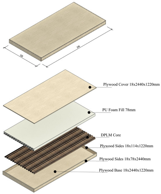
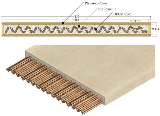
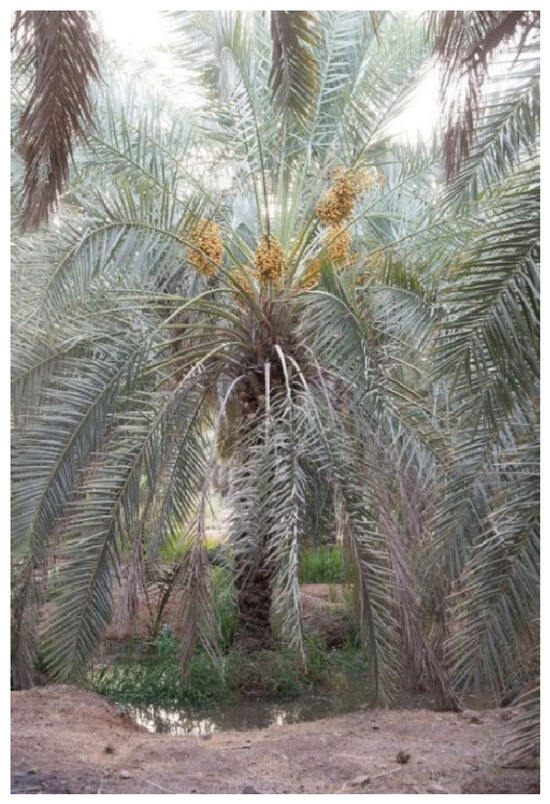
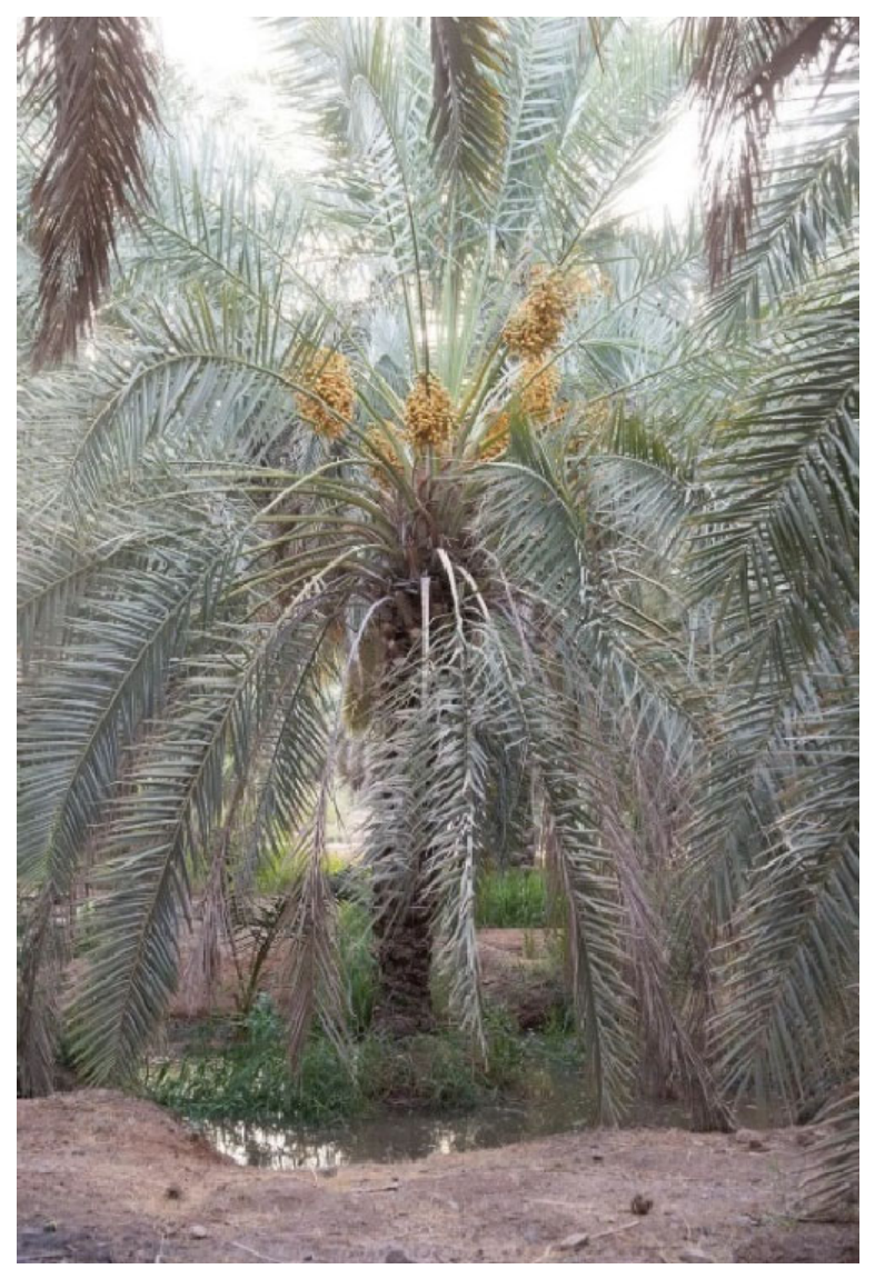
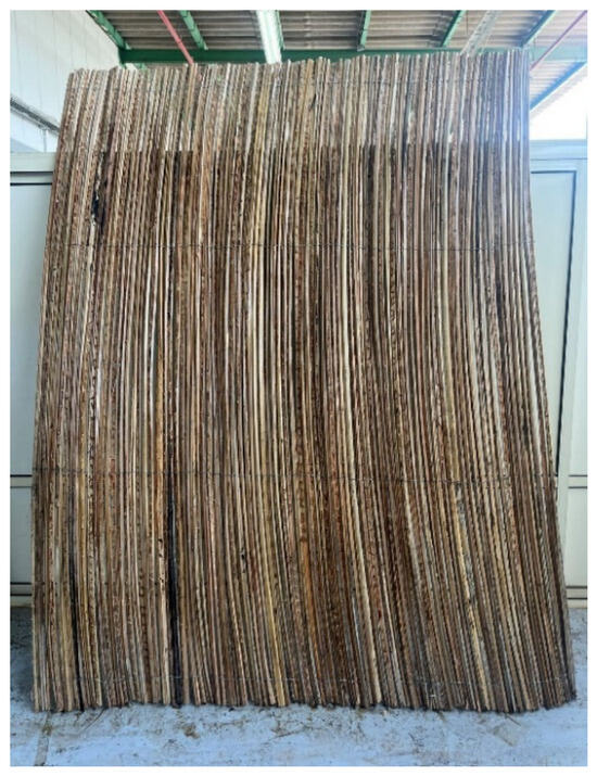
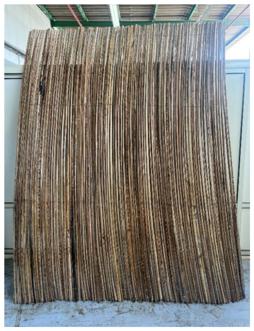
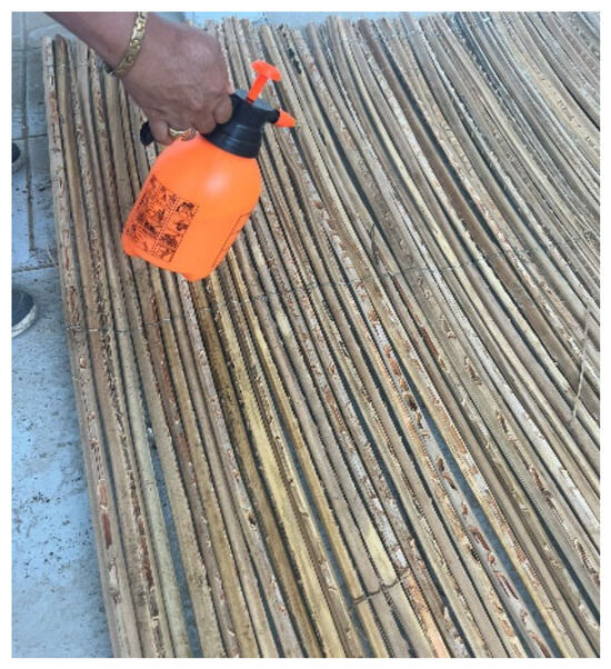
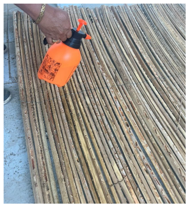
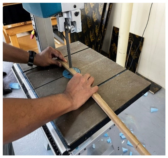
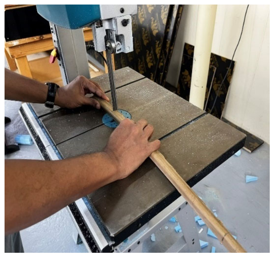
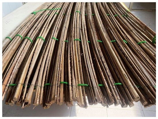
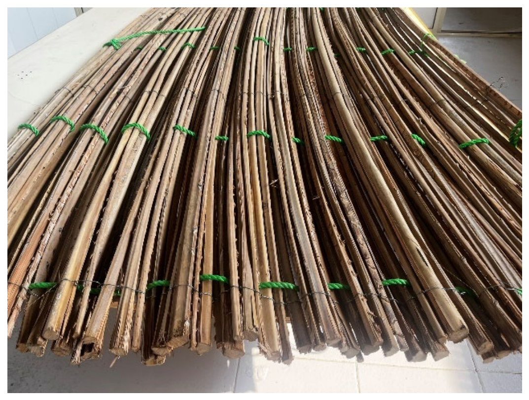
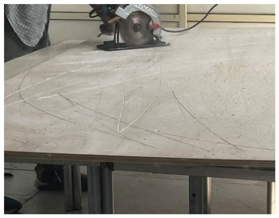
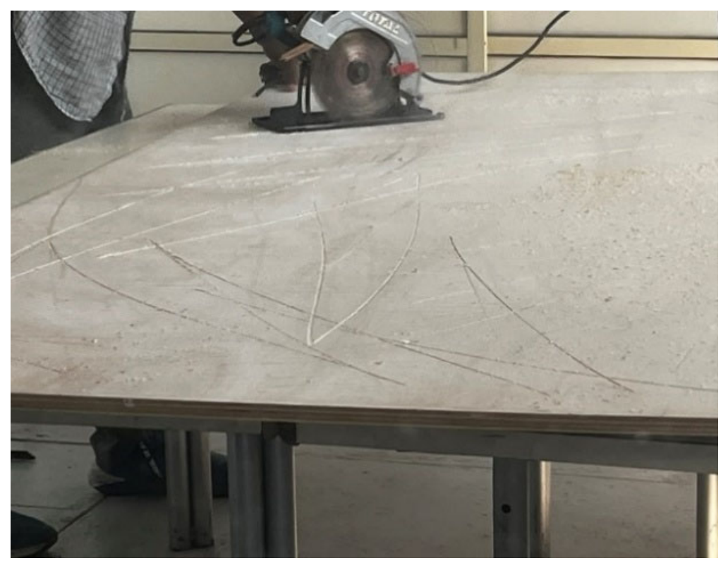
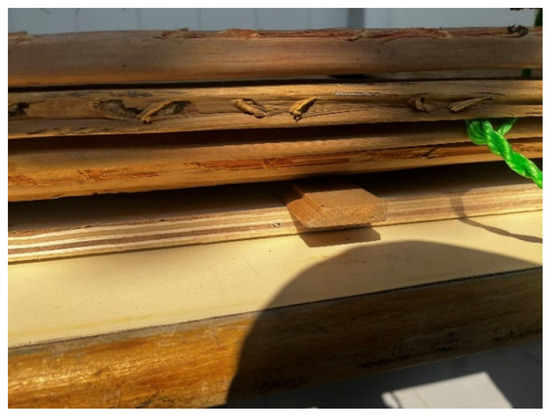
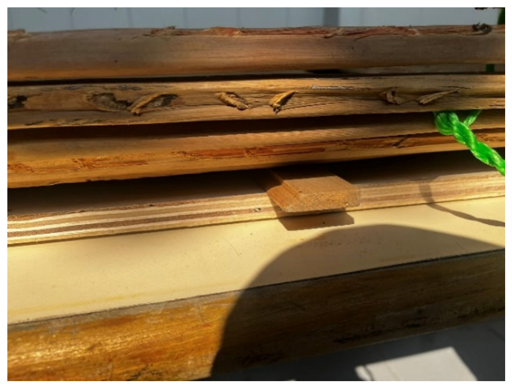
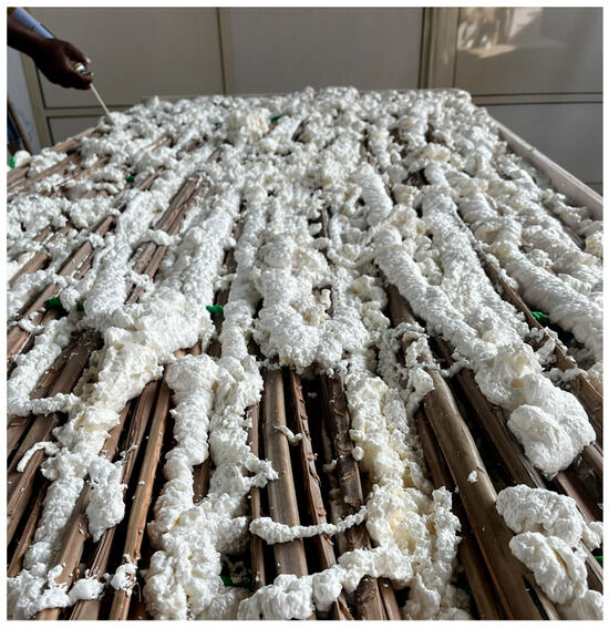
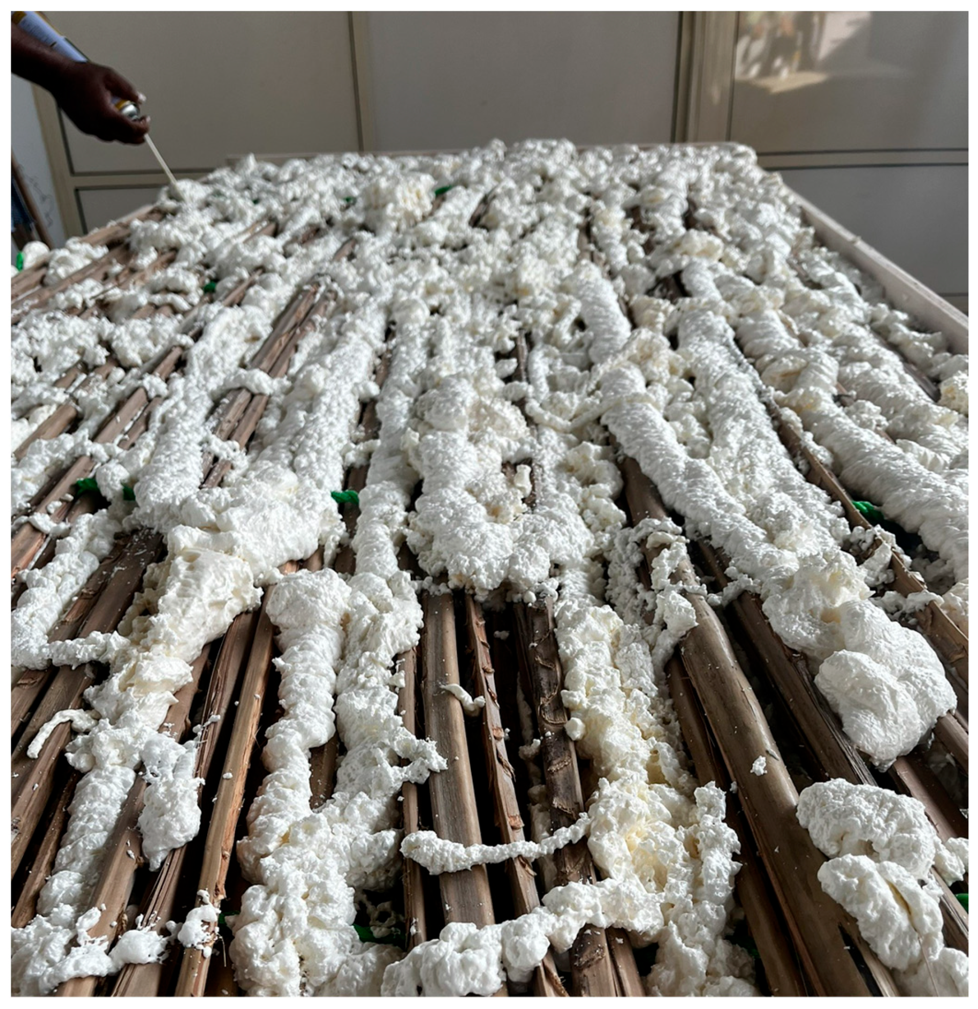
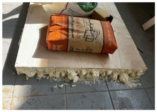
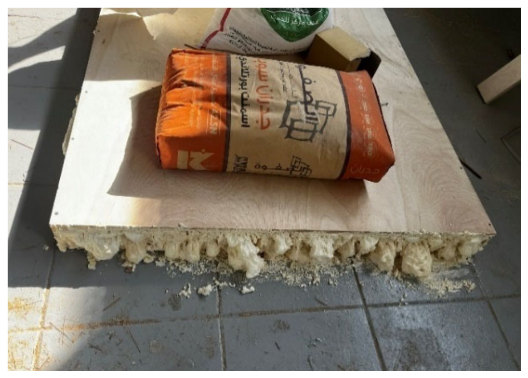
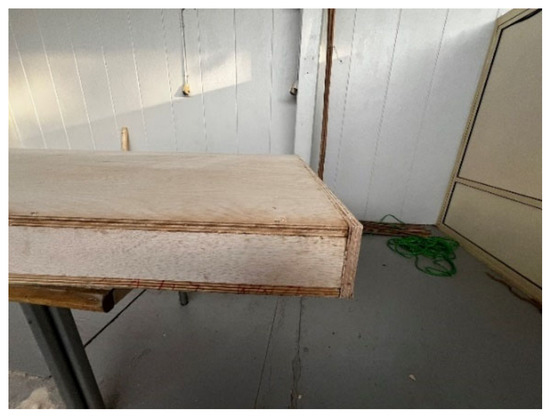
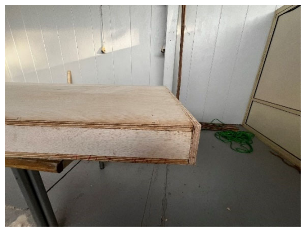
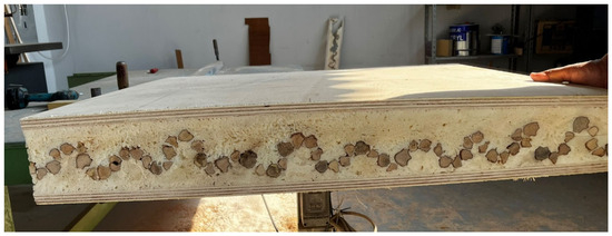
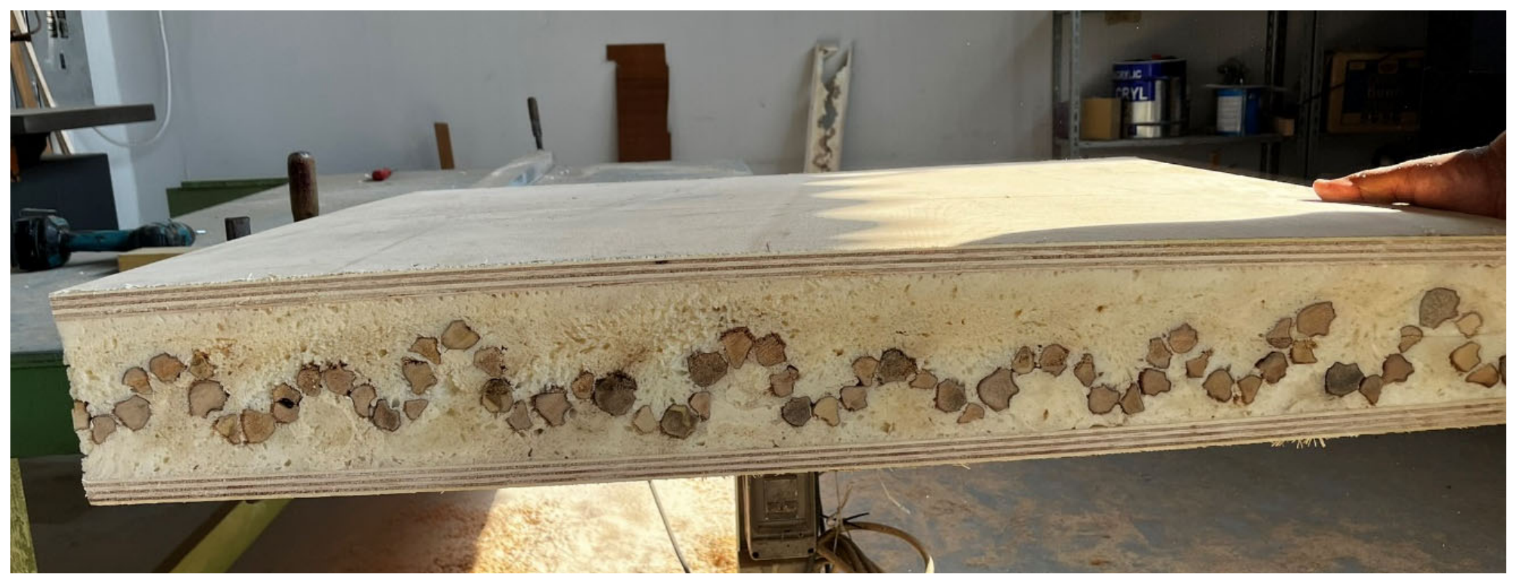
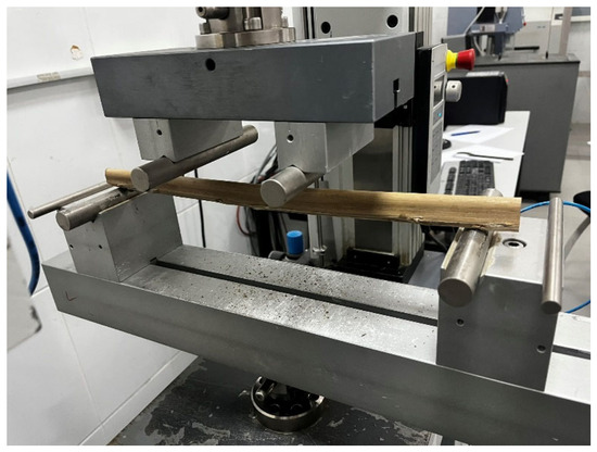
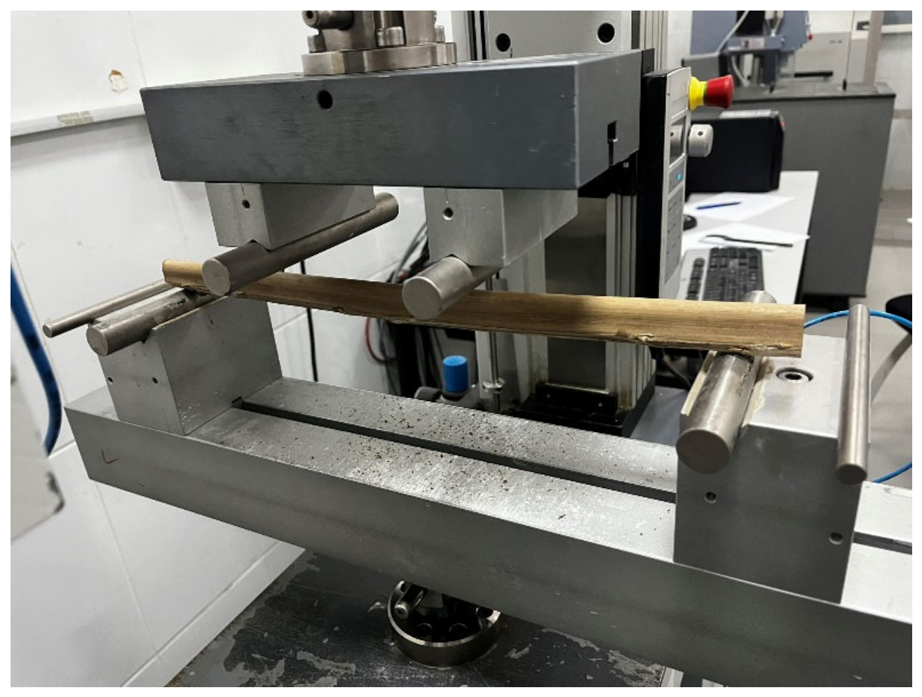
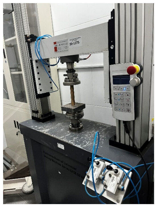
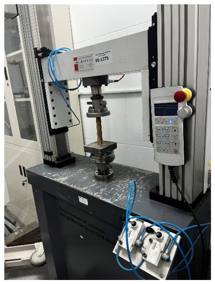
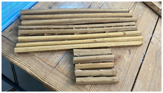
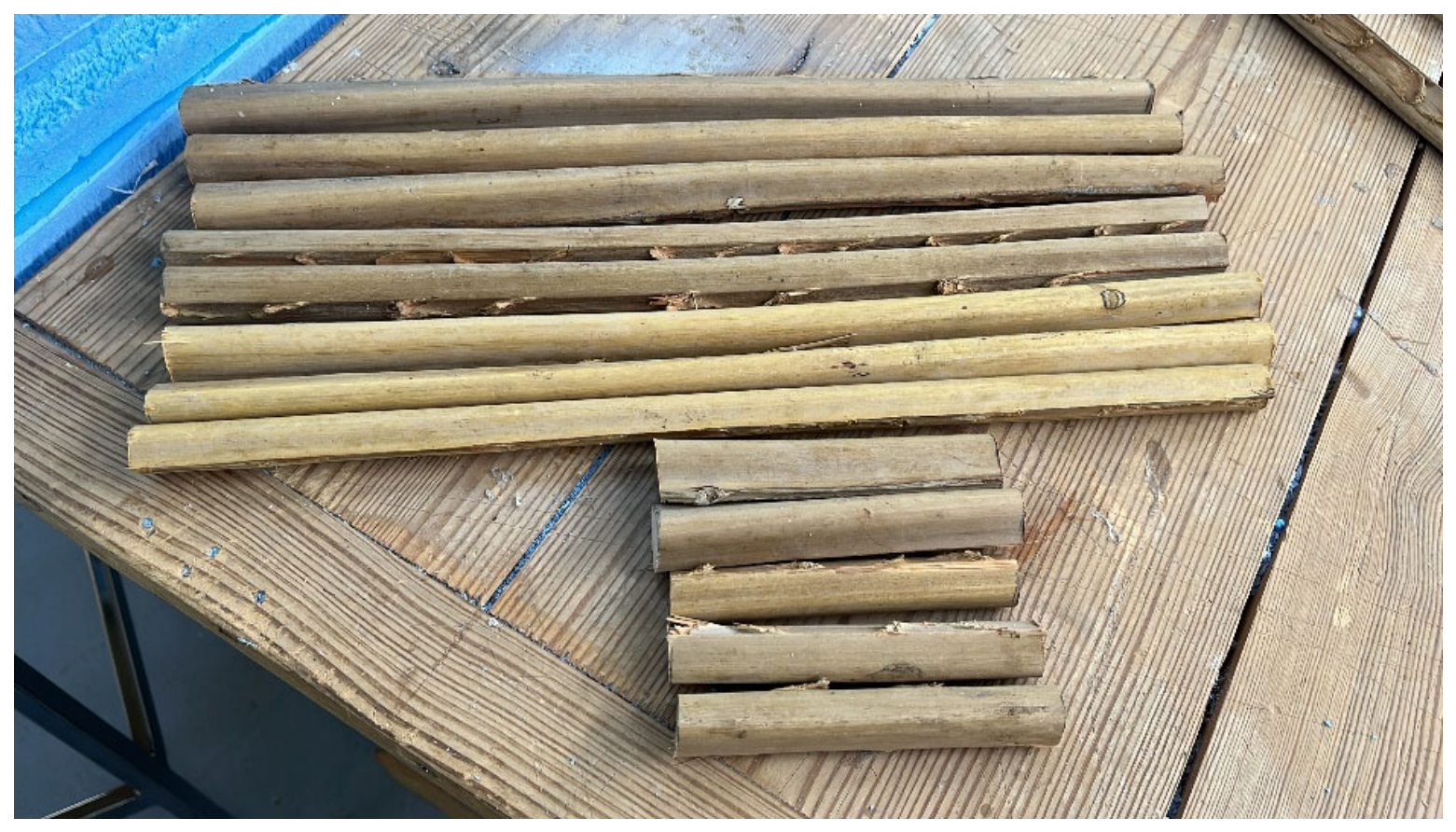
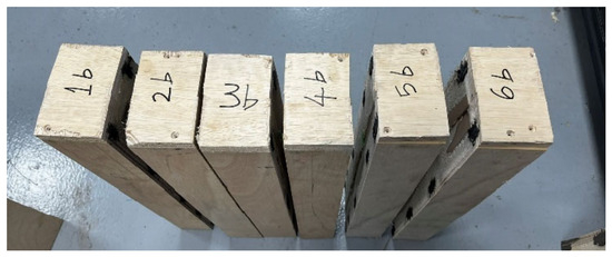
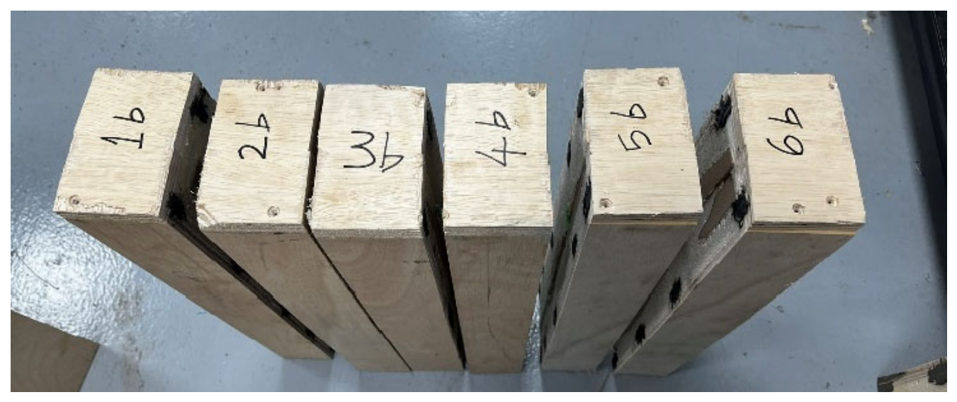
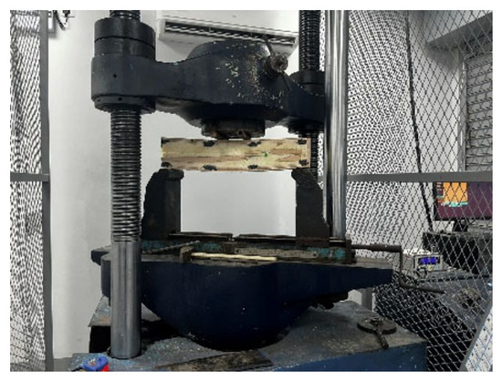
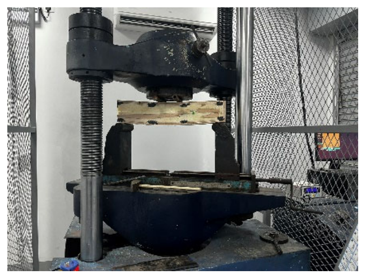
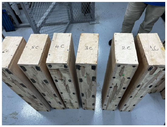
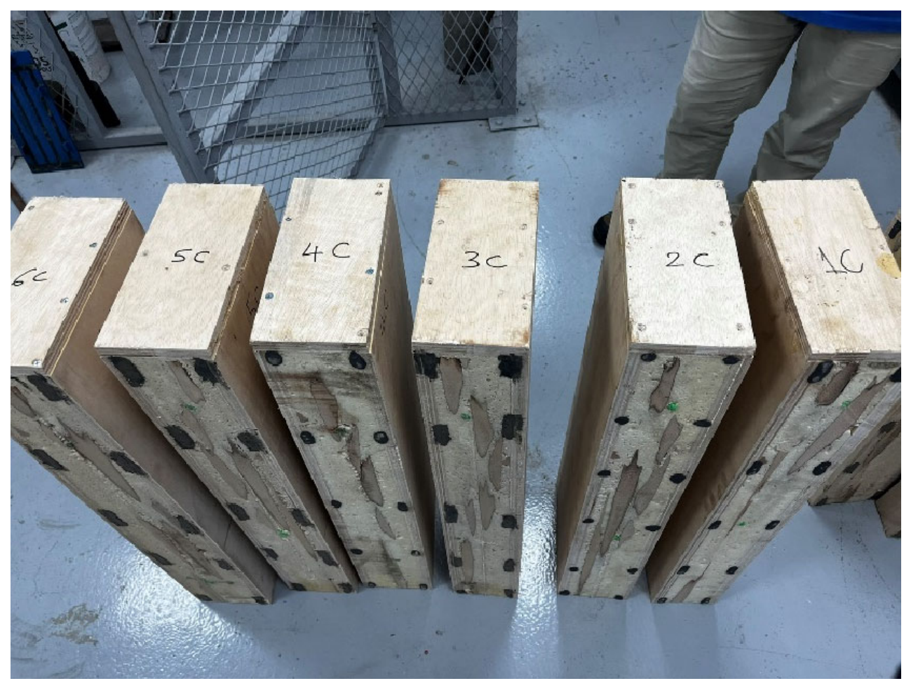
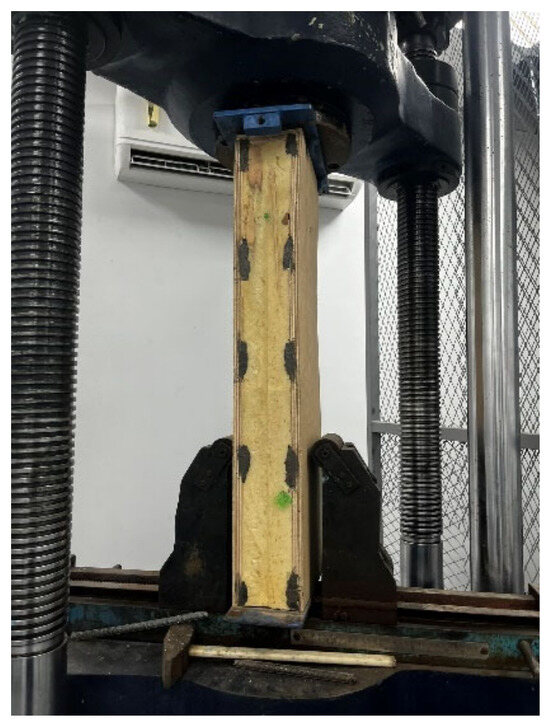
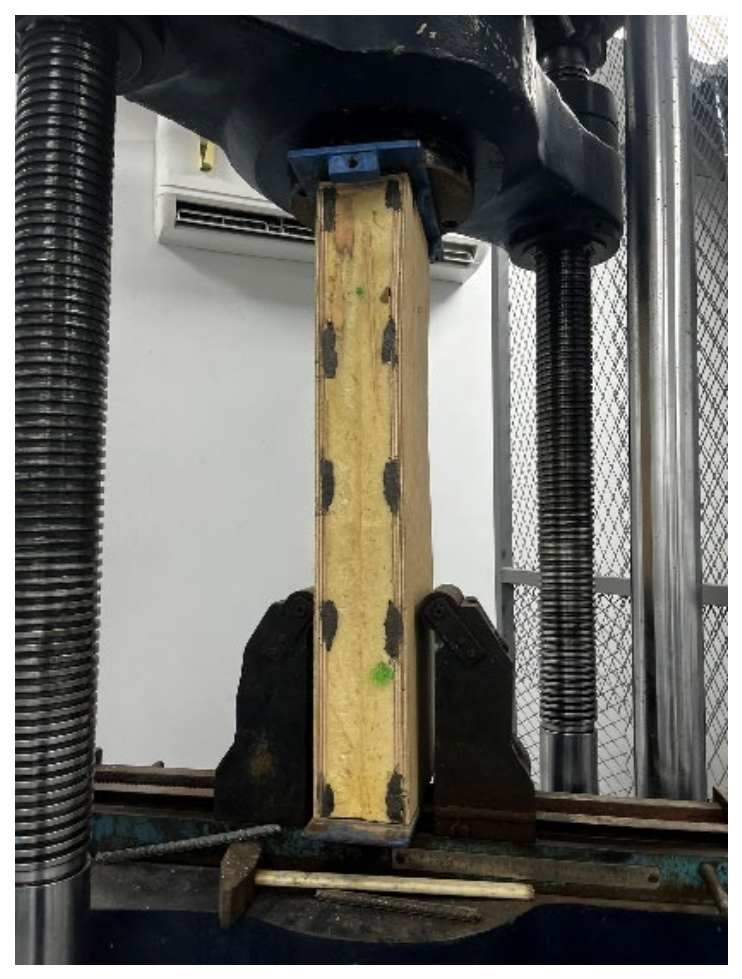
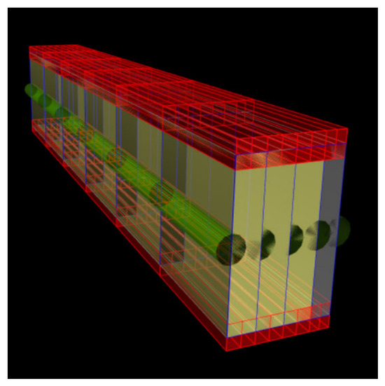
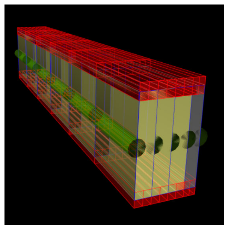
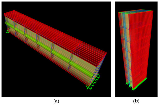
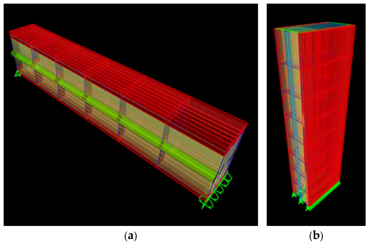
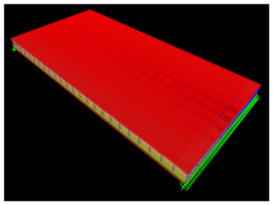
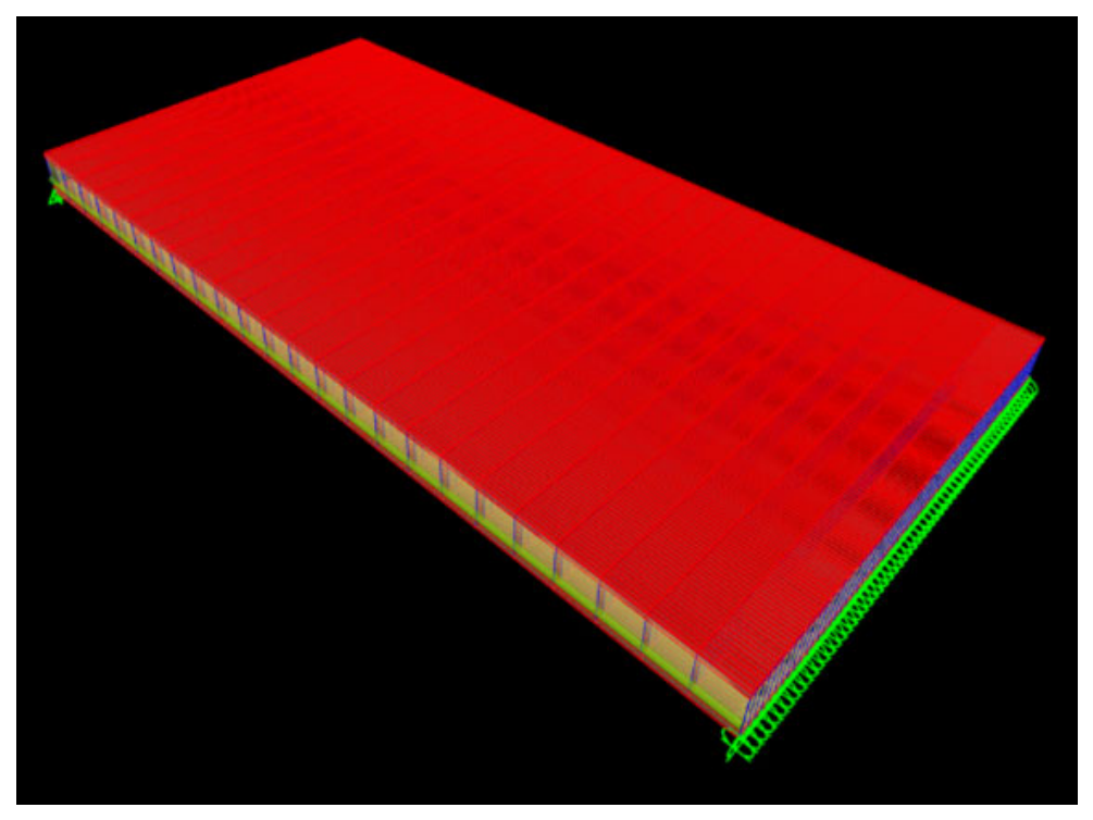
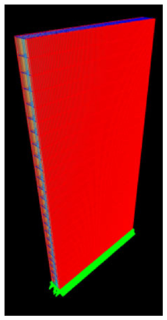
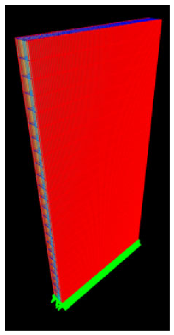
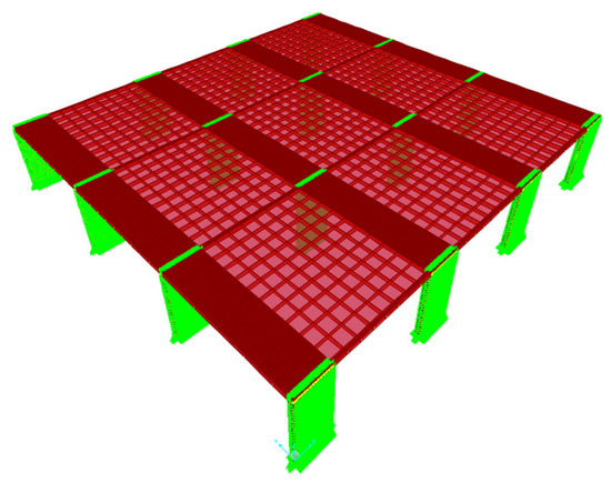
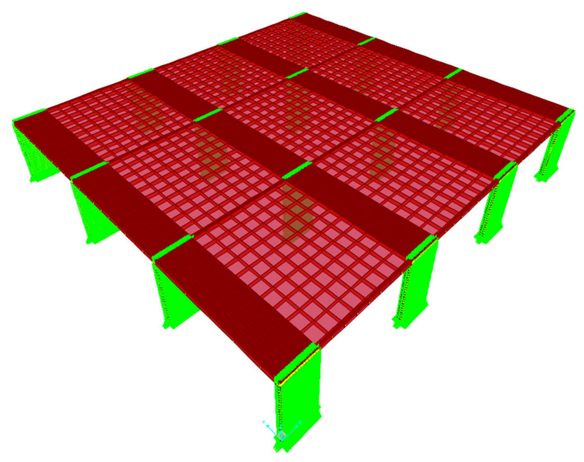
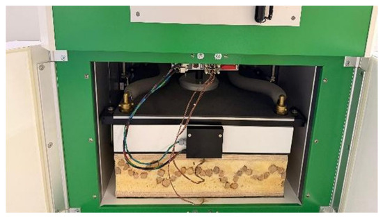
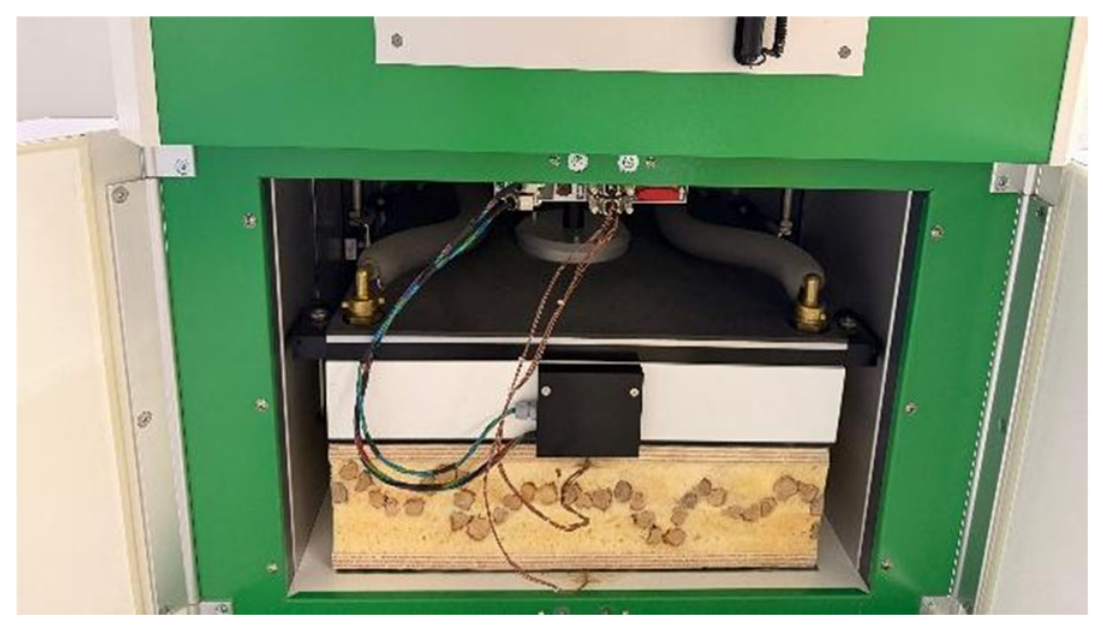
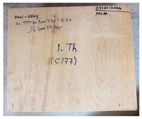
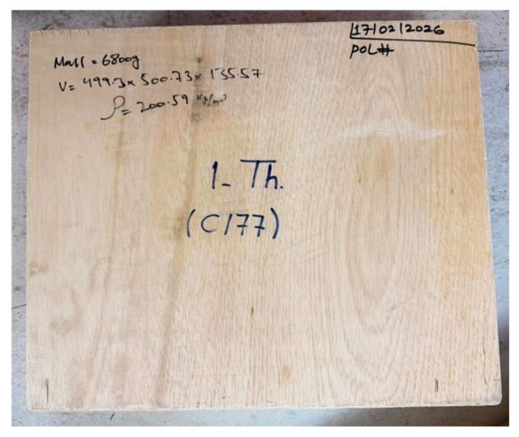
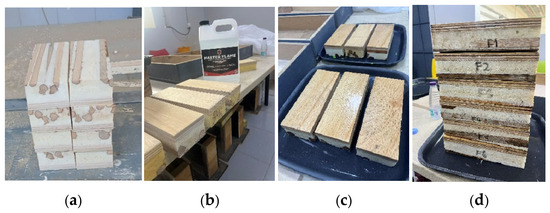
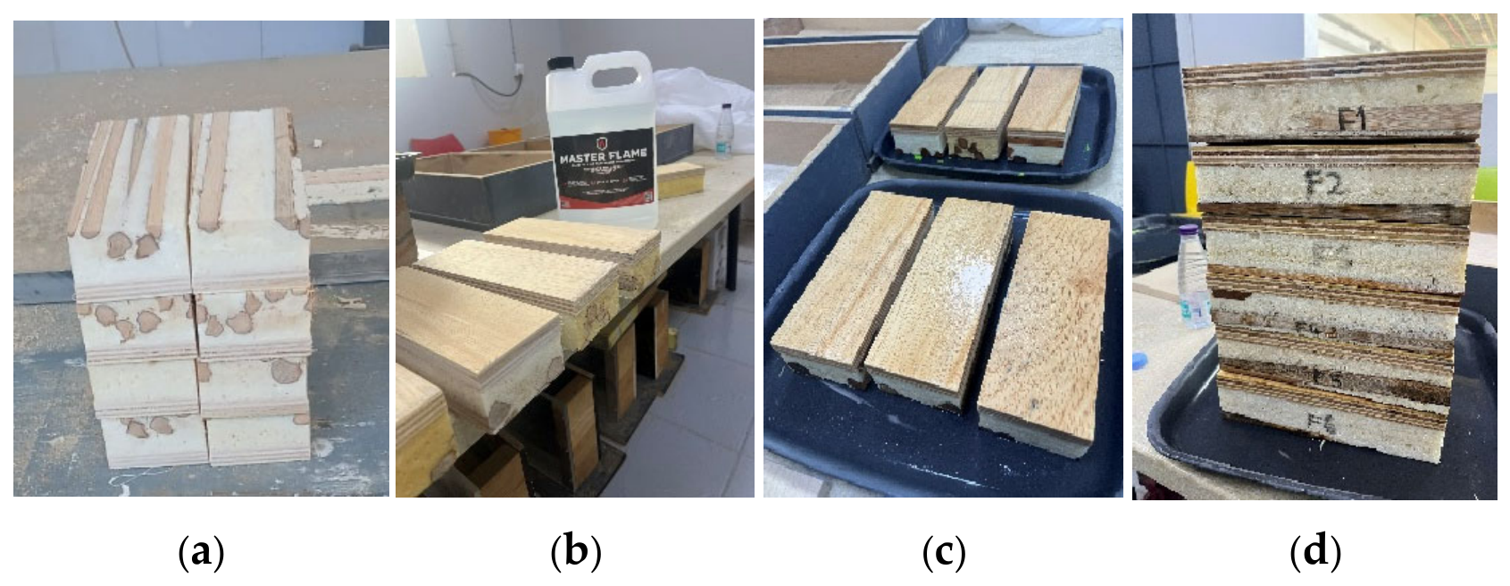
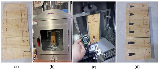
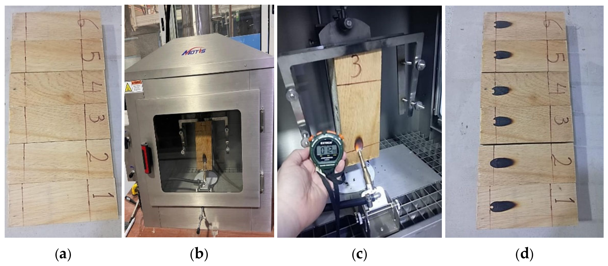
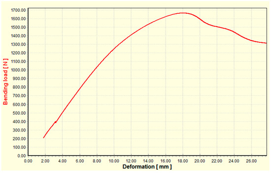
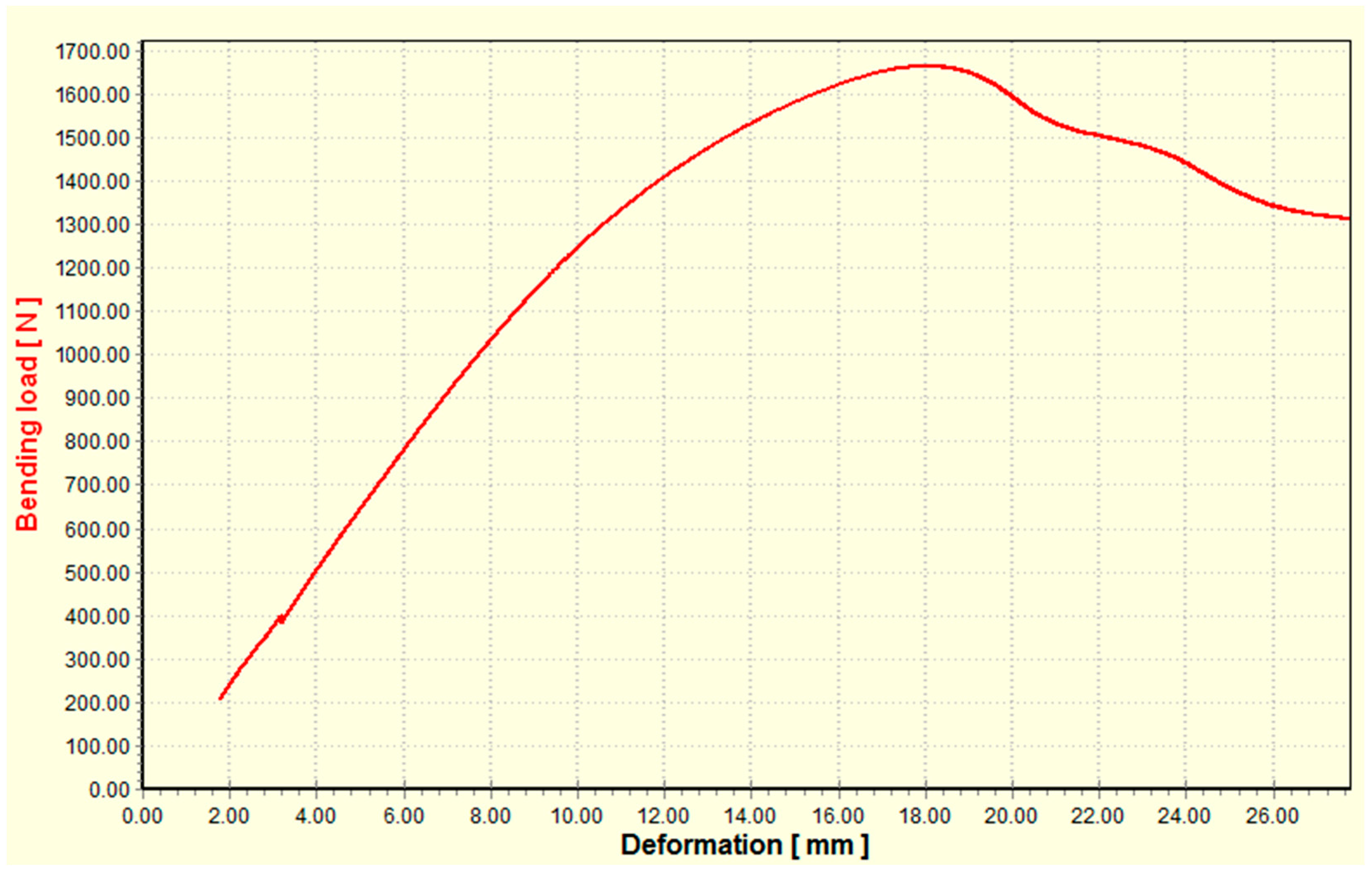
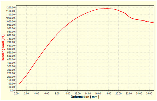
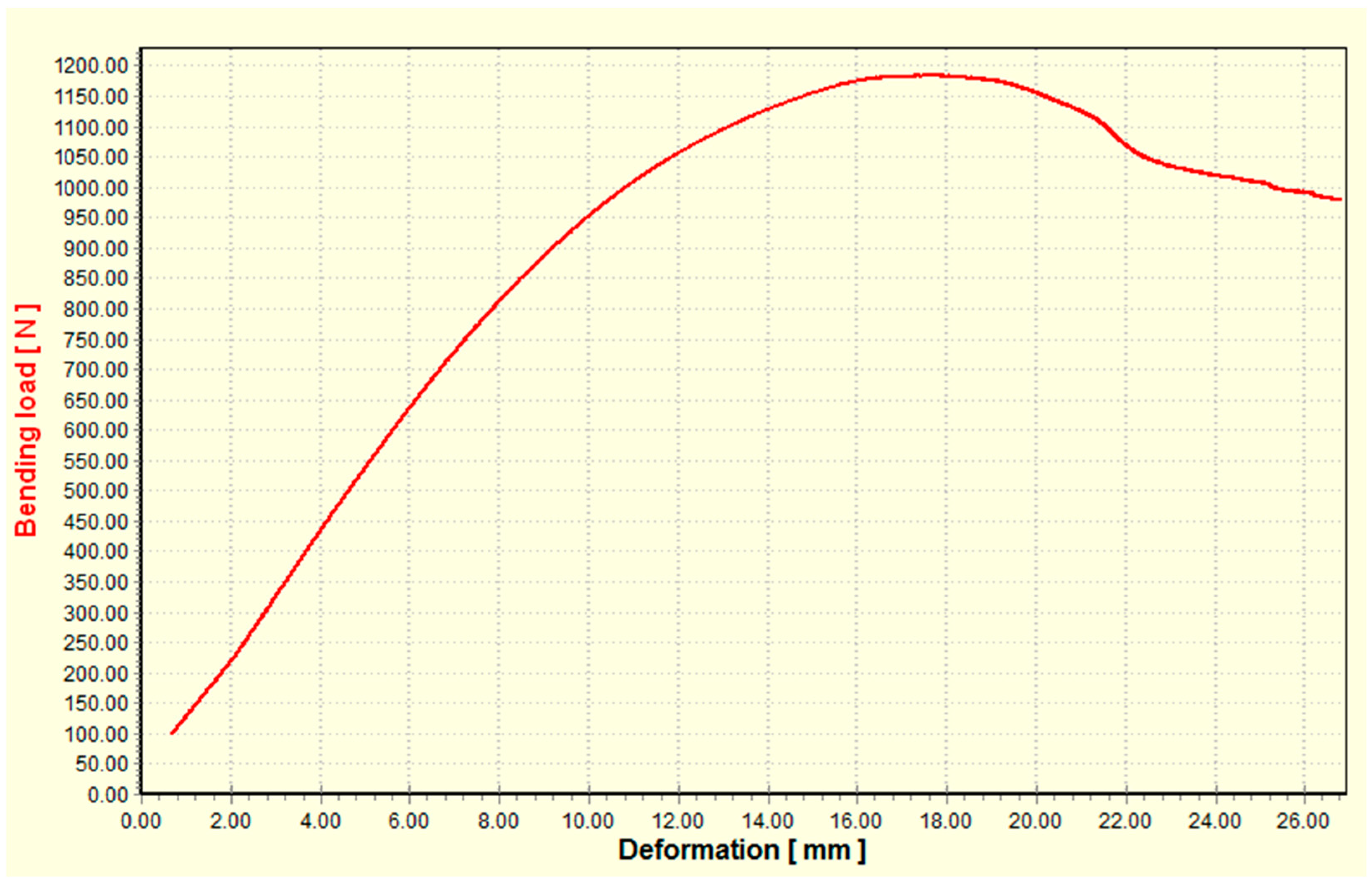
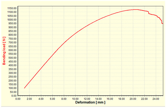
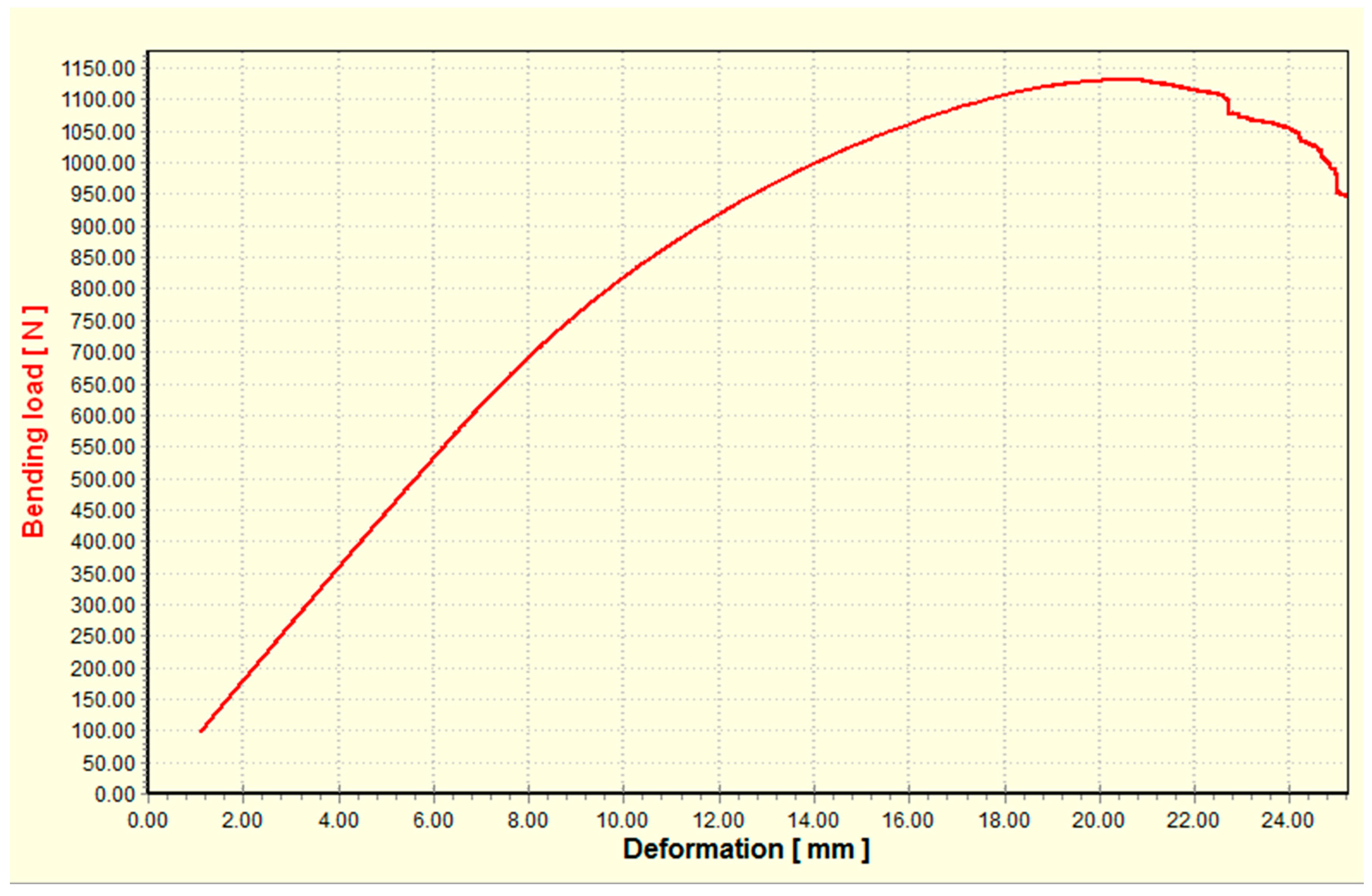
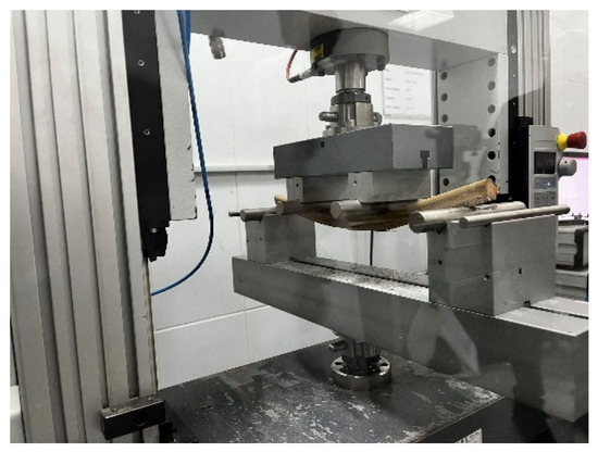
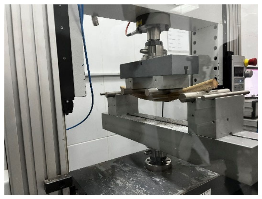
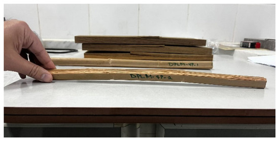
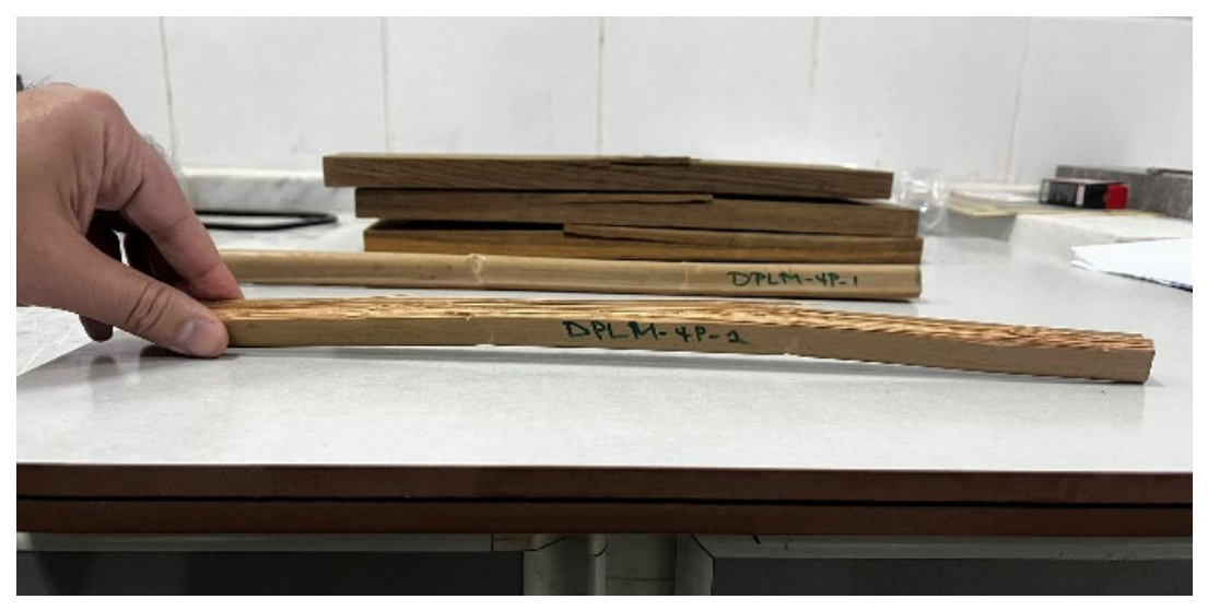
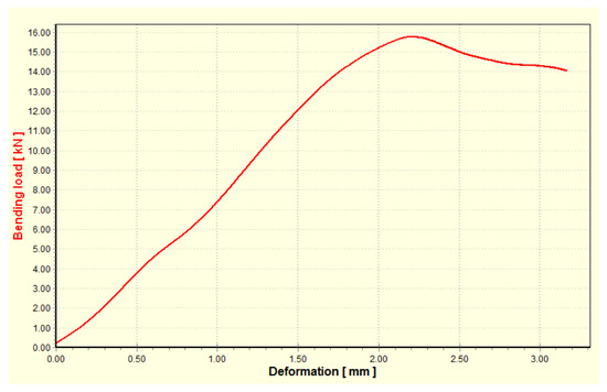
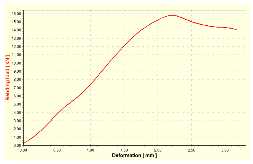
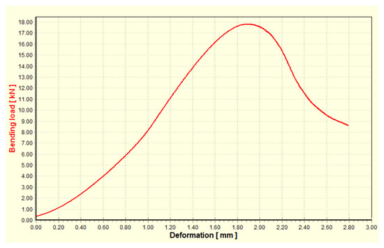
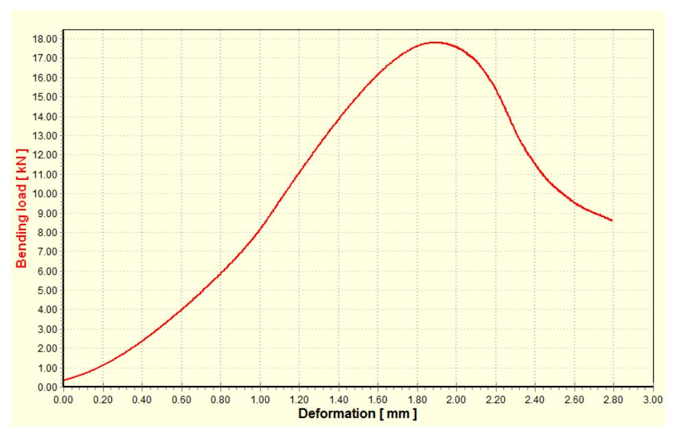
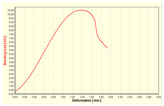
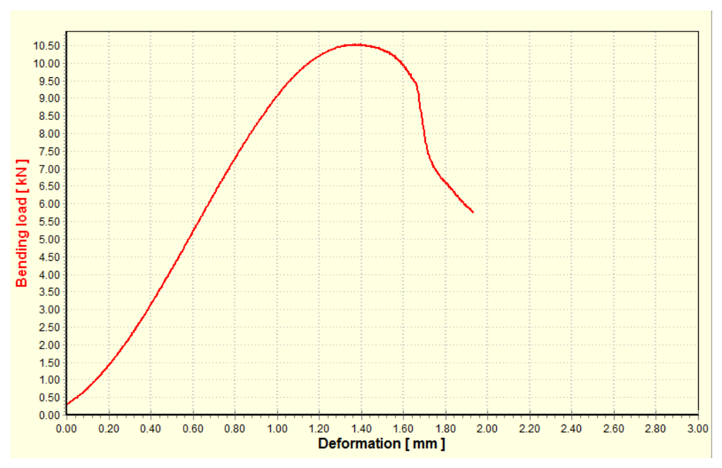
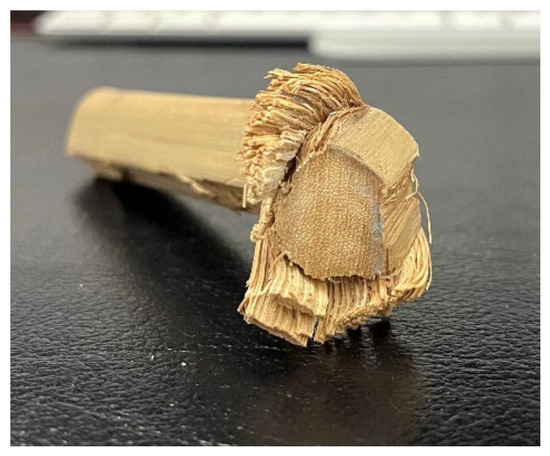
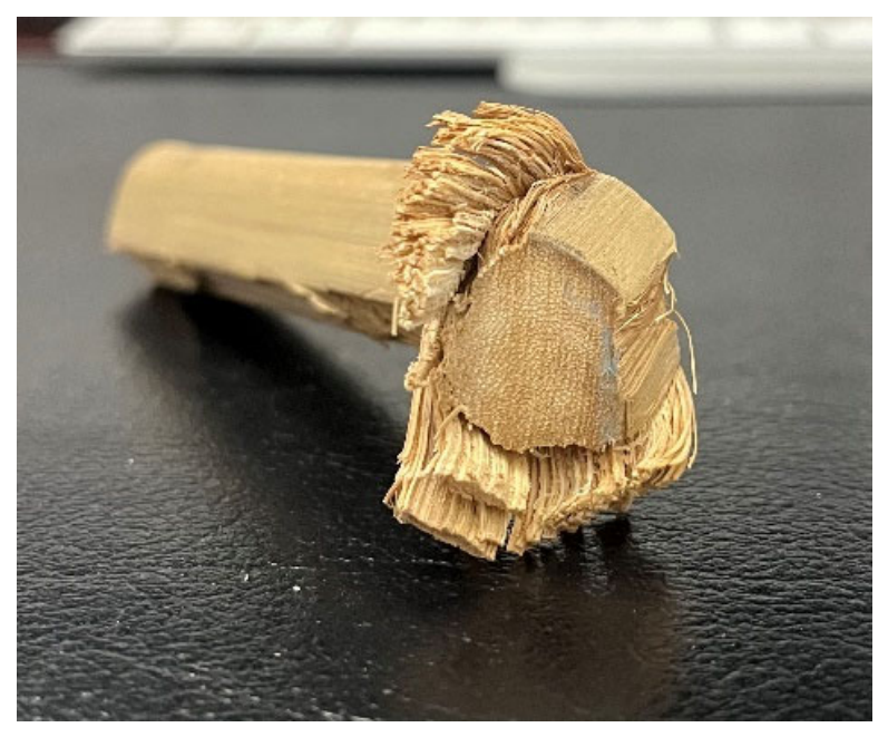
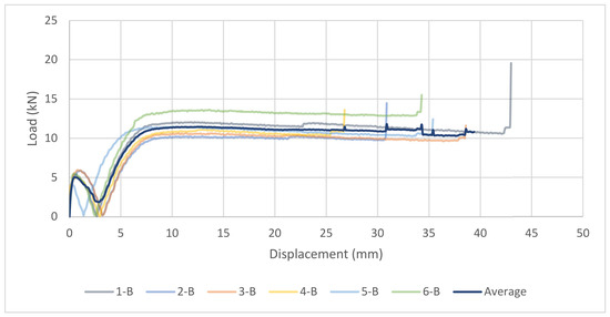
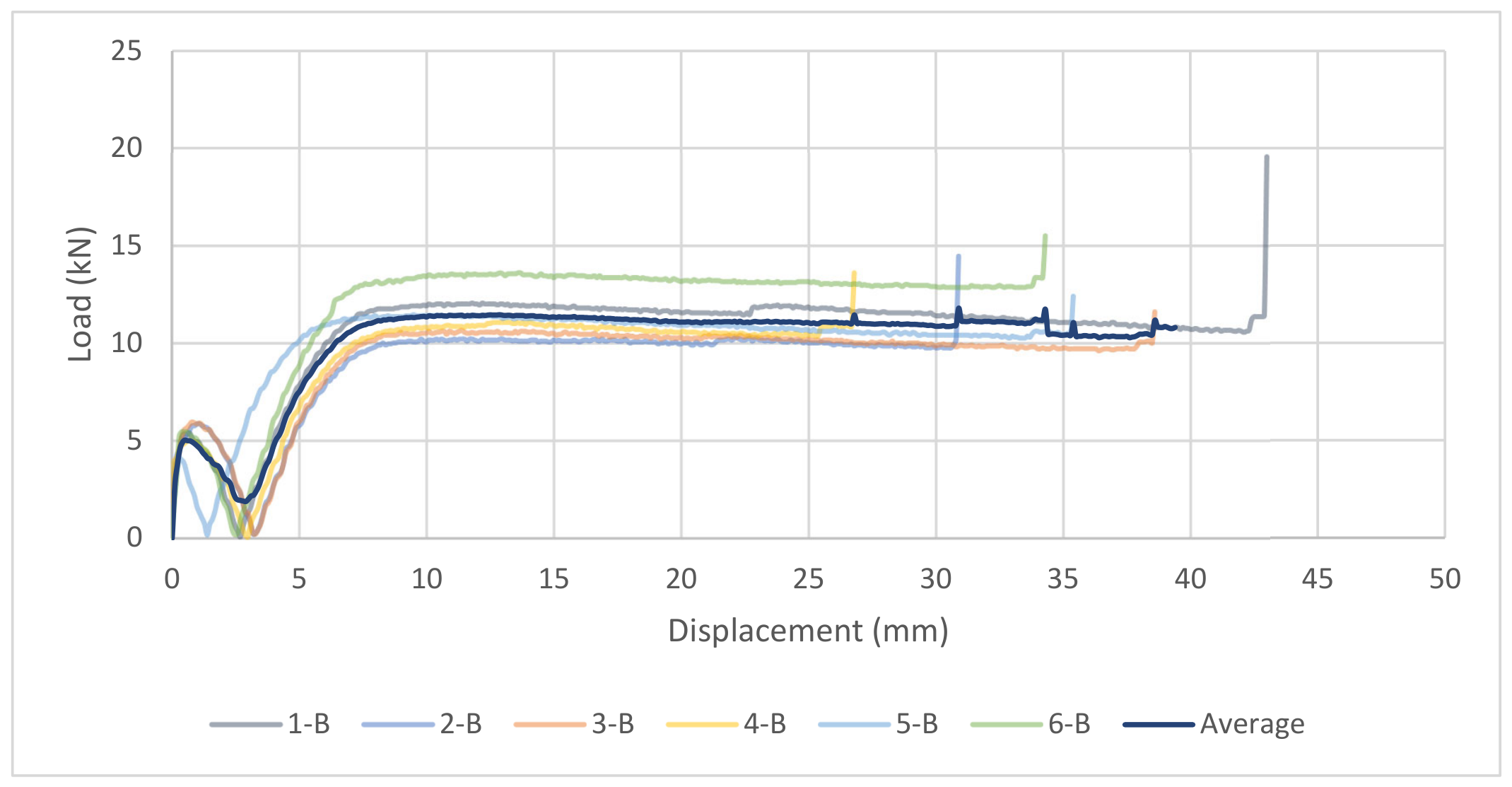
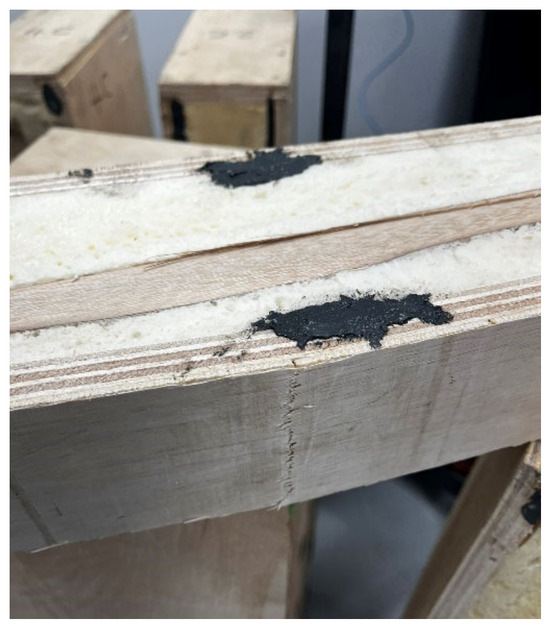
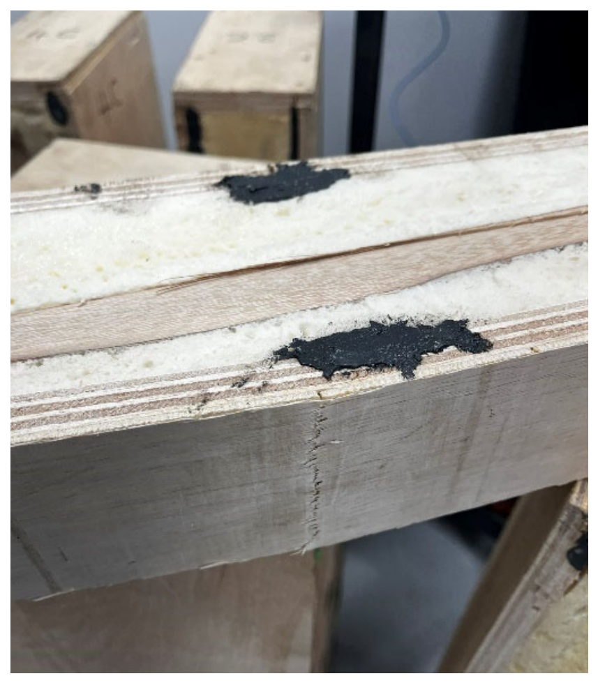
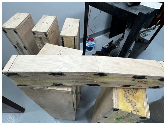
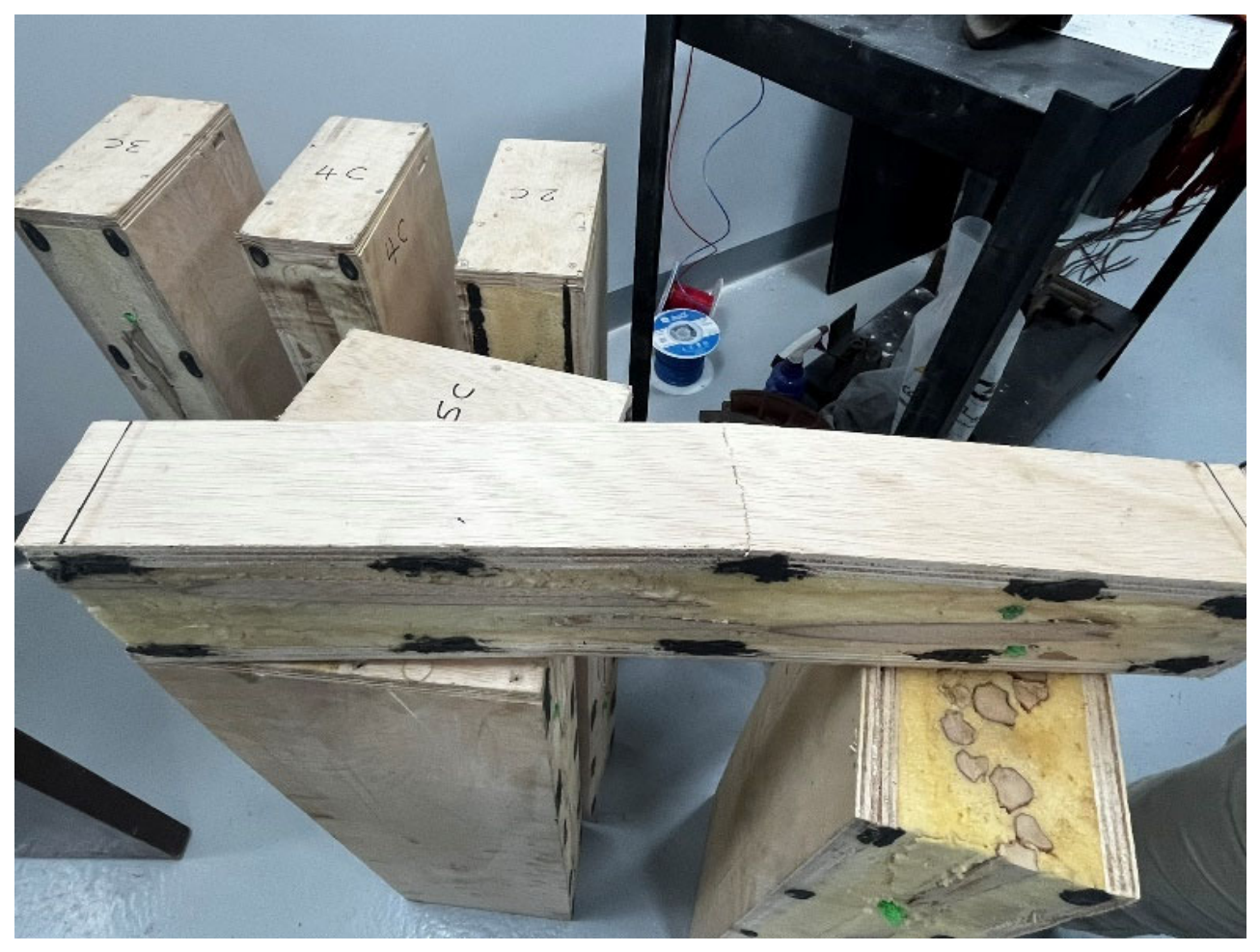
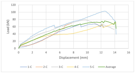
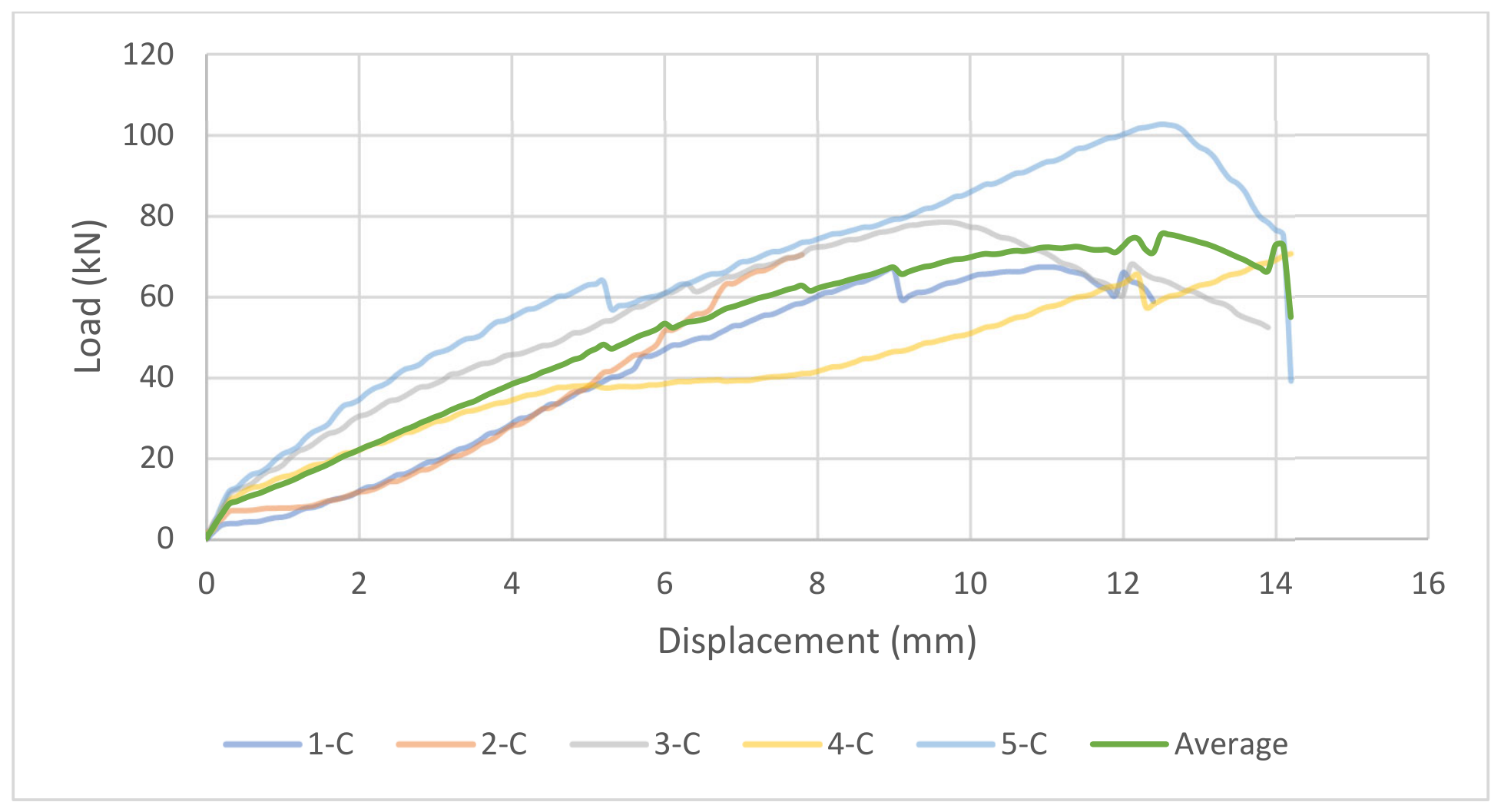
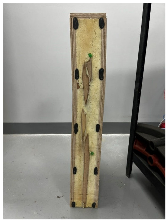
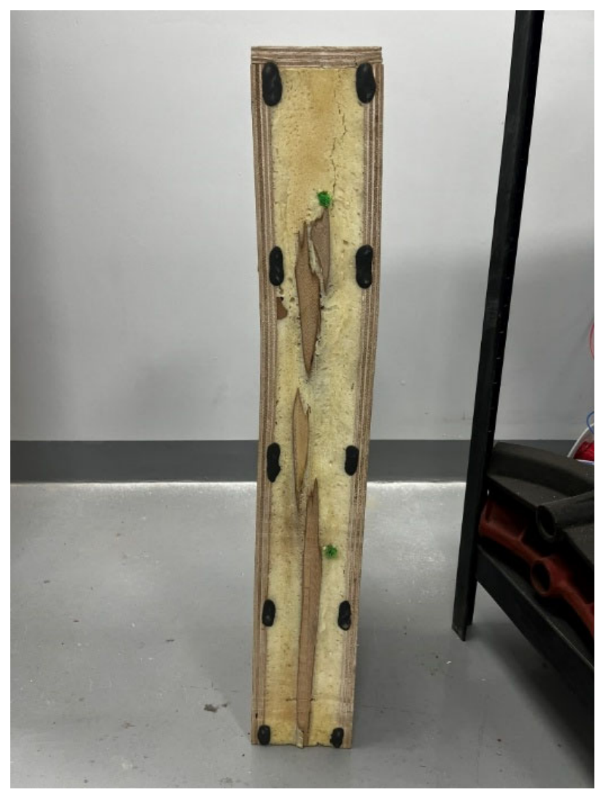
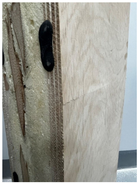
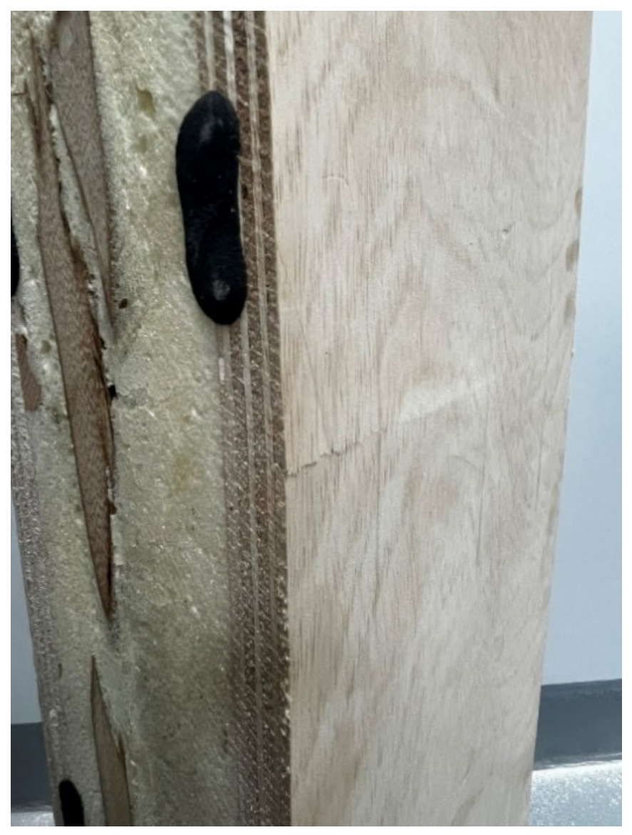
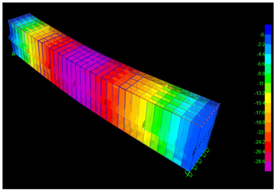
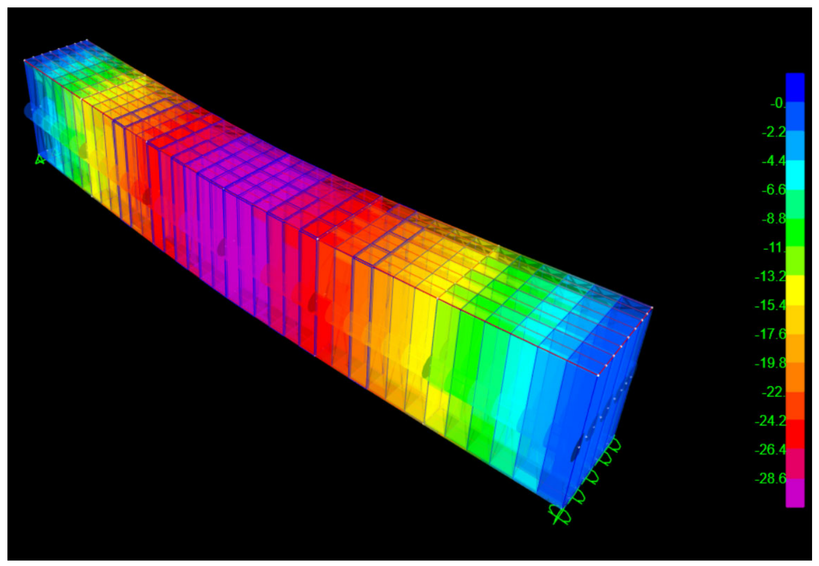
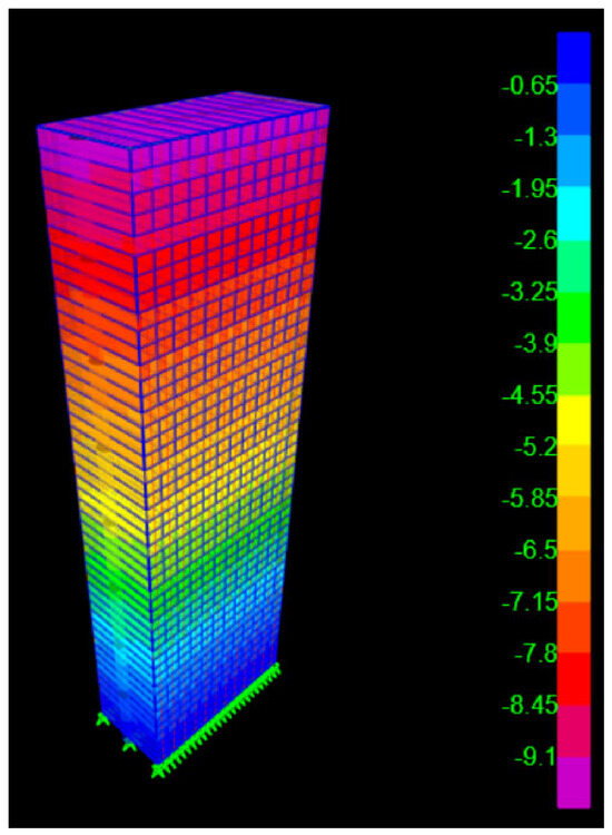
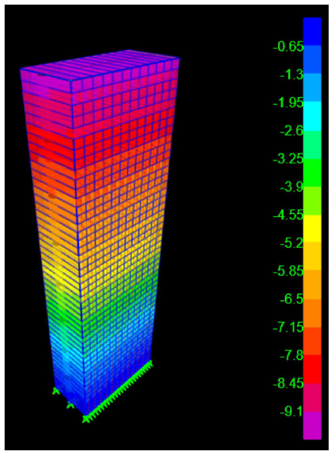
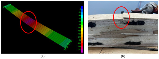
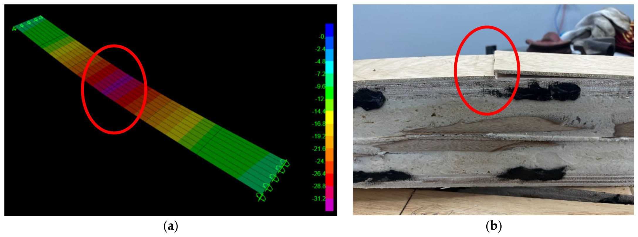
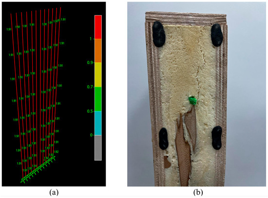
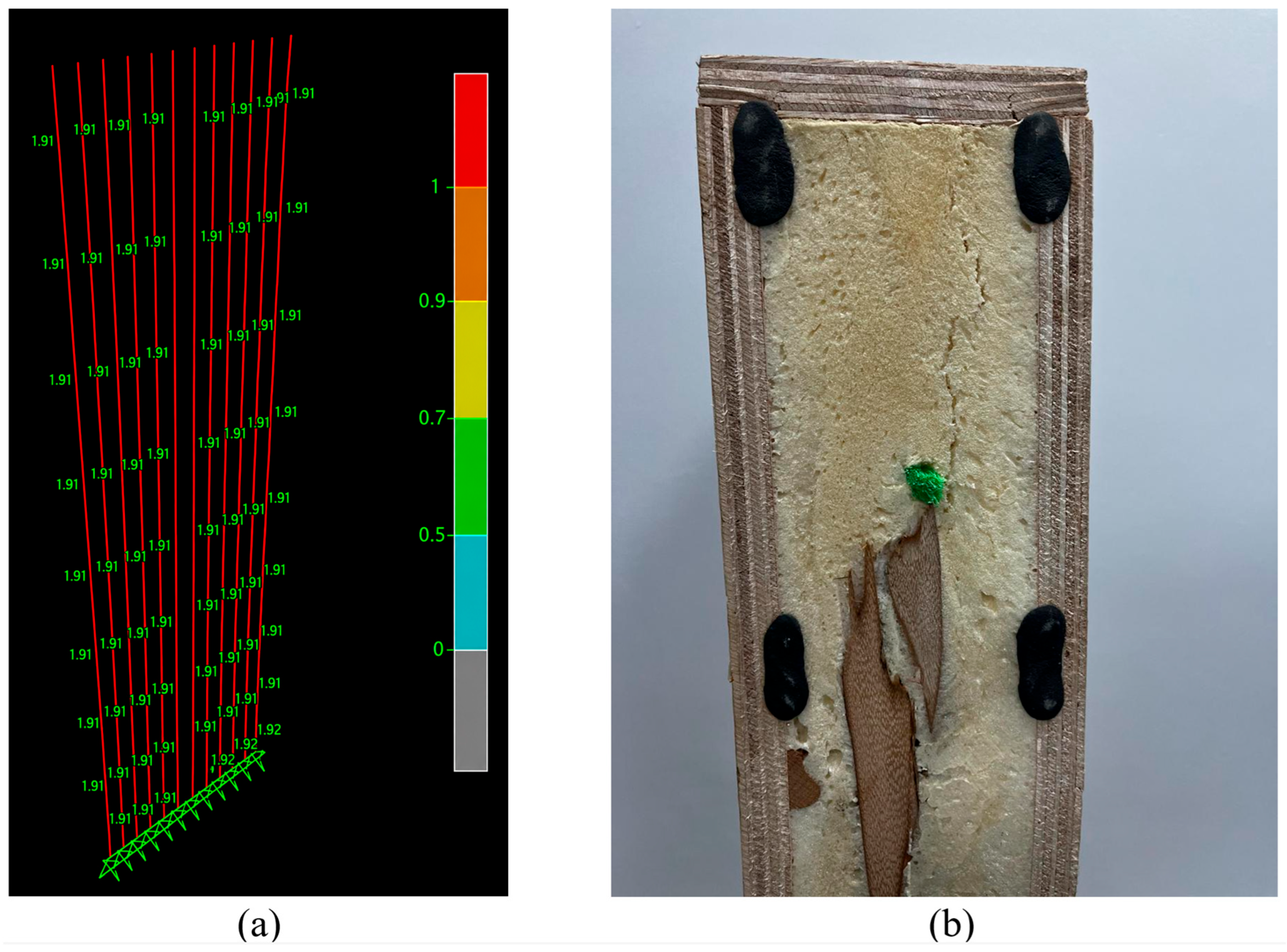
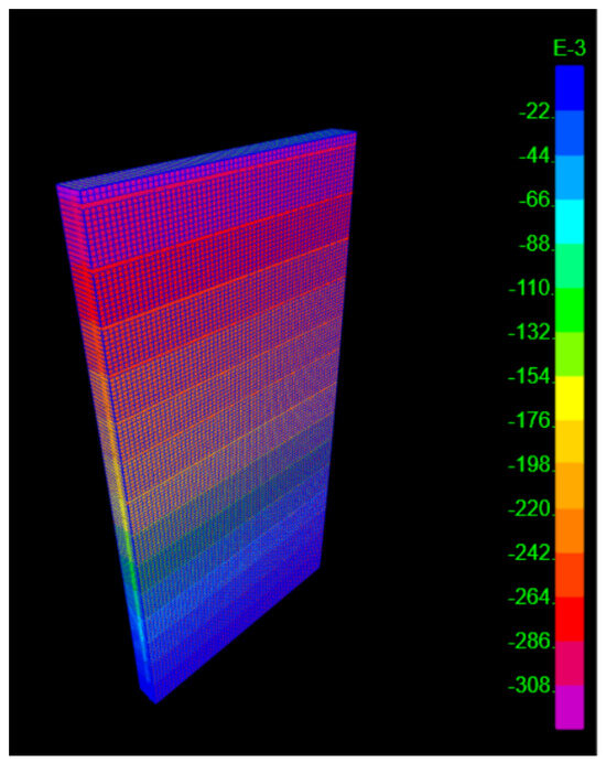
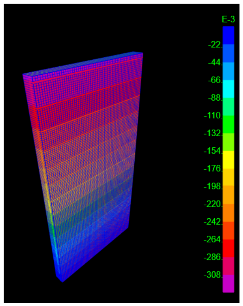
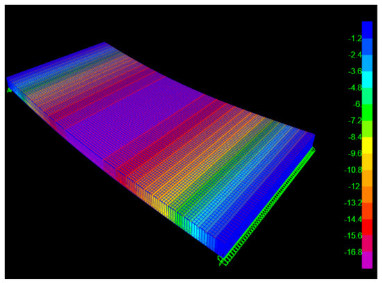
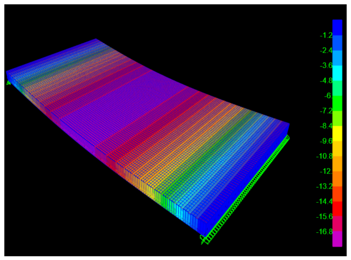
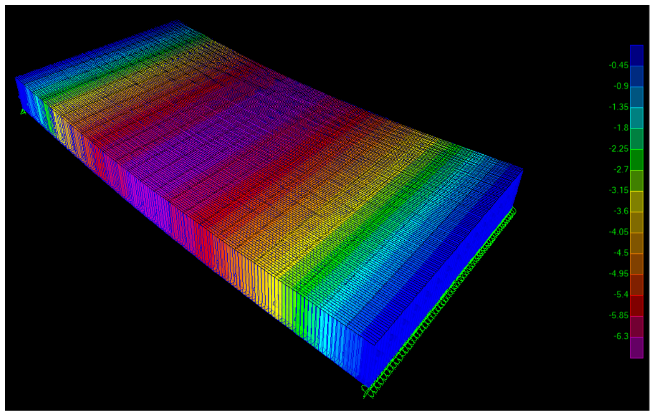
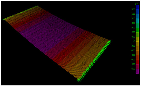
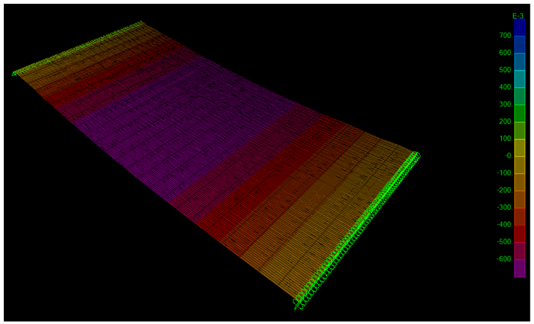
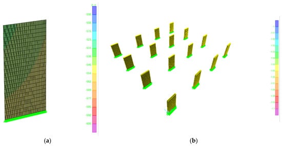
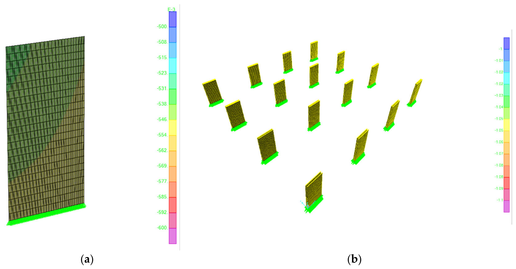
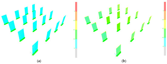
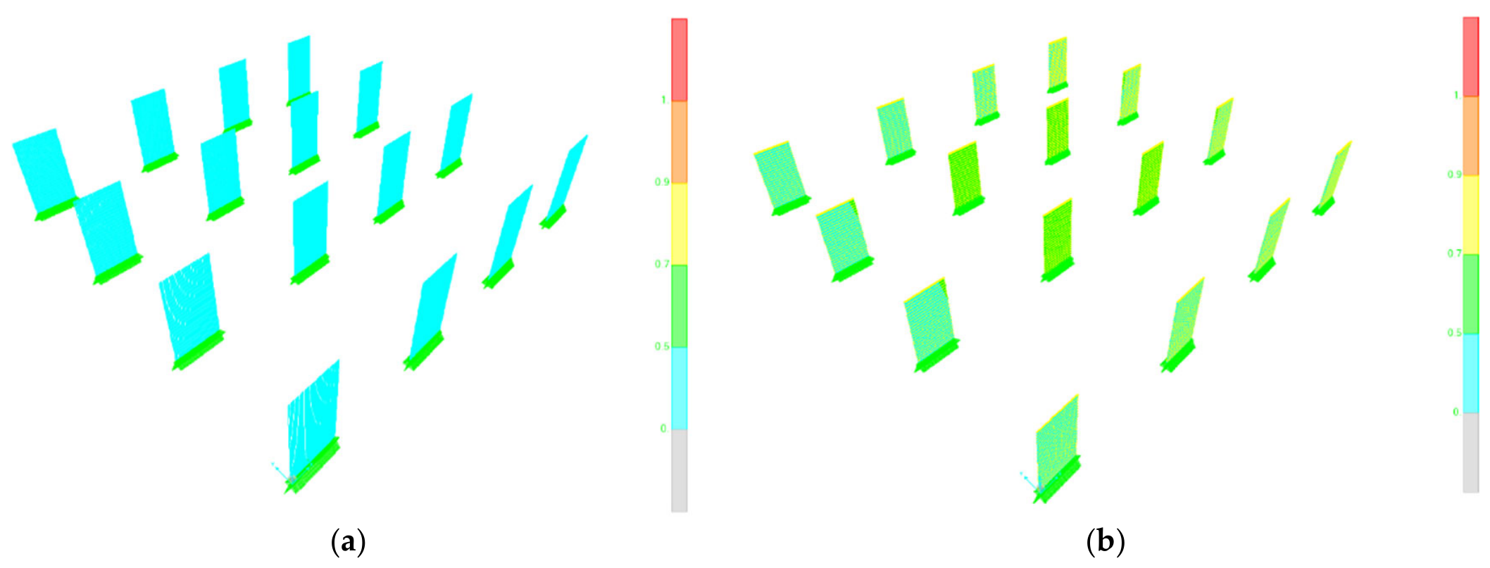

Disclaimer/Publisher’s Note: The statements, opinions and data contained in all publications are solely those of the individual author(s) and contributor(s) and not of MDPI and/or the editor(s). MDPI and/or the editor(s) disclaim responsibility for any injury to people or property resulting from any ideas, methods, instructions or products referred to in the content. |
© 2026 by the authors. Licensee MDPI, Basel, Switzerland. This article is an open access article distributed under the terms and conditions of the Creative Commons Attribution (CC BY) license.