


Abstract
This research focuses on the seismic performance of post-fire sleeve-grouted connection prefabricated shear walls. The effects of fire duration, axial compression ratio, aspect ratio, and longitudinal bar diameter on the failure mode, horizontal bearing capacity, ductility, and energy dissipation capacity of post-fire sleeve-grouted connection prefabricated shear walls were analyzed using the ‘sequential thermo-mechanical coupling’ method. The research results indicate that the failure mode of post-fire sleeve-grouted connection prefabricated shear walls undergoes significant changes, with damage mainly concentrated in the horizontal joints and the area above the sleeves. As the duration of fire increases, the damaged area gradually extends upwards until the bearing capacity is lost. With the increase in fire duration, the peak and failure loads of post-fire sleeve-grouted connection prefabricated shear walls show a significant downward trend, and the ductility decreases by 7.98%, 12.17%, 15.21%, and 20.15%, respectively. When the axial compression ratio is less than 0.3, both the horizontal bearing capacity and ductility of post-fire sleeve-grouted connection prefabricated shear walls increase with the increase in axial compression ratio. However, when the axial compression ratio exceeds 0.3, the horizontal bearing capacity and ductility of post-fire sleeve-grouted connection prefabricated shear walls decrease with the increase in axial compression ratio, and the failure mode of post-fire sleeve-grouted connection prefabricated shear walls transitions from flexural-shear failure to flexural failure as the axial compression ratio increases. As the aspect ratio increases, the energy dissipation capacity of post-fire sleeve-grouted connection prefabricated shear walls increases, but the horizontal bearing capacity and ductility decrease. Increasing the diameter of longitudinal bars can improve the horizontal bearing capacity of the specimens but reduce the ductility and increase the energy dissipation capacity. The research results provide a theoretical basis for the safety assessment, repair, and reinforcement of post-fire sleeve-grouted connection prefabricated shear walls, and have important reference value for practical engineering applications.
1. Introduction
Building fires, as a highly destructive and relatively common disaster, can significantly degrade the mechanical properties of building materials due to the high temperatures they generate, thereby affecting the overall safety of the structure and potentially leading to its collapse in severe cases [1,2,3,4]. In recent years, prefabricated structures have been vigorously promoted by the government due to their advantages such as high construction efficiency, high industrialization level, and environmental friendliness [5,6,7,8]. As the main lateral load-resisting components of prefabricated structures, prefabricated shear walls play a crucial role in seismic resistance [9]. Considering the impact of high temperatures from fires on the mechanical properties of materials such as steel bars, concrete, and grouting materials, it is necessary to study the seismic performance of prefabricated shear walls after fires.
Currently, numerous scholars have conducted in-depth research on the seismic performance of shear walls after fires, discovering that indicators such as bearing capacity, stiffness, energy dissipation capacity, and ductility of concrete shear walls will decrease to varying degrees after fire. Xiao, Liu Guirong, et al. [10,11] conducted low-cycle repeated quasi-static loading tests on concrete shear walls after fire, finding that the bearing capacity, stiffness, and energy dissipation capacity of concrete shear walls decrease after fire. Ni et al. [12] studied the seismic performance of reinforced concrete structural walls after fire, discovering that fire damage reduces the bearing capacity and stiffness of RC walls under repeated loads; at failure, damage from fire exposure may transfer to the web of the wall; the wall thickness, boundary element length, and axial compression ratio have a significant impact on the seismic performance of walls after fire. Hu Xuefeng et al. [13] found that the ductility of steel plate shear walls decreases after fire; the longer the exposure time to fire, the more significant the decrease in seismic performance, and steel plate shear walls exposed to fire on both sides have worse seismic performance than those exposed to fire on one side. Xu Yuyi et al. [14] found that the presence of concealed columns can improve the stiffness and energy dissipation capacity of shear walls after fire, but does not increase their bearing capacity. Wei Fangfang et al. [15] discovered that the duration of fire has a significant negative impact on the seismic performance of double-steel-plate–concrete composite shear walls, and an increase in axial compression ratio exacerbates the degradation of bearing capacity. Xu et al. [16] found that prolonged fire duration and an increased fire-exposed surface area reduce the bearing capacity, ductility, and energy dissipation capacity of high-strength concrete shear walls. Conversely, an increase in the aspect ratio can enhance the ductility of high-strength concrete shear walls but decrease their bearing capacity. Xiong et al. [17] discovered that the horizontal bearing capacity, initial stiffness, deformation capacity, and energy dissipation capacity of new composite shear walls after exposure to fire are lower than those of unexposed specimens. However, the overall decrease is relatively minor, and appropriately increasing the width-to-thickness ratio can significantly enhance the horizontal bearing capacity and energy dissipation capacity of new composite shear walls after exposure to fire. Zheng Jiahao [18] studied the seismic performance of prefabricated shear walls with sleeve-grouted connections after exposure to fire and found that the bearing capacity, stiffness, and post-yield energy dissipation capacity of prefabricated shear walls decrease with a prolonged exposure time. The bearing capacity of shear walls with sleeve-grouted connections decreases significantly after exposure to fire. Li Shengcai [19] proposed a new type of prefabricated shear wall and conducted a study on double-sided exposure to fire. It was found that a prolonged exposure time reduces the wall’s stiffness, as well as bearing and energy dissipation capacity. An increase in the axial compression ratio can enhance the bearing capacity and stiffness but decrease the ductility and energy dissipation capacity. Jiang Feng [20] established a degraded four-line restoring force model by analyzing the characteristics of skeleton curves and found that prolonged exposure to fire leads to a decrease in the stiffness reduction factor of prefabricated shear walls. An excessively high axial compression ratio can reduce the fullness of the hysteresis loop and potentially decrease ductility. Currently, research on the seismic performance of shear walls after fire mainly focuses on cast-in-place concrete shear walls, with less attention paid to the seismic performance of prefabricated shear walls after fire. However, unlike cast-in-place concrete shear walls, the seismic performance of prefabricated shear walls depends not only on material properties but also on joint connections [21]. Prefabricated shear walls with different joint connection methods exhibit certain differences in seismic performance [22].
The present study complements the experimental investigation of Zheng et al. [18] by establishing a sequential thermo-mechanical finite element framework and conducting a controlled parametric analysis of post-fire seismic behavior. Ref. [18] provides experimental evidence for the JLQ3 wall, whereas the present numerical study extends the analysis to 18 cases covering fire exposure duration (0–120 min), axial compression ratio (0.1–0.5), wall aspect ratio (1.0–3.0), and longitudinal reinforcement diameter (12–16 mm). In addition, a related numerical study by Zheng et al. [23] considered selected effects of fire duration, axial compression ratio, and reinforcement diameter. The present study further considers the wall aspect ratio within the same numerical framework and evaluates the combined effects of these variables on failure mode, horizontal bearing capacity, displacement ductility, and energy dissipation. The resulting parameter trends provide a numerical basis for post-fire performance assessment of sleeve-grouted prefabricated shear walls.
Recent experimental studies provide material- and connection-specific evidence for post-fire grouted sleeve behavior. Xue et al. [24] experimentally characterized the thermal properties and temperature-dependent compressive strength of sleeve grouting materials up to 900 °C. Wang et al. [25] investigated the post-fire cyclic behavior of grouted sleeve connections, while Liu et al. [26] quantified the degradation of grout bond performance under cyclic loading after fire. These studies provide the material and connection basis for the constitutive assumptions adopted in the present numerical framework.
2. Model Establishment and Validation
2.1. Model Overview
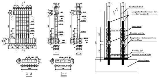
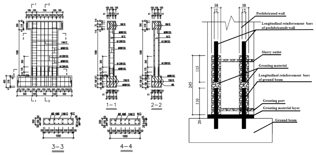
The research object of this paper is the JLQ3 prefabricated shear wall with sleeve grouting connections, selected from reference [18]. Figure 1 illustrates the specific structure of the JLQ3 prefabricated shear wall with sleeve grouting connections. The test specimen primarily consists of a wall body, a top loading beam, and a ground beam, all constructed with concrete of strength grade C40 and reinforcement of strength grade HRB400. Specifically, the dimensions of the wall body are 200 mm × 1000 mm × 1600 mm, the dimensions of the concealed column are 200 mm × 200 mm × 1600 mm, and the sectional dimensions of the loading beam are 300 mm × 300 mm × 1260 mm. The sleeve used in the test specimen is a GTQ4J12 fully grouted sleeve, constructed from Q345B material, with a length of 245 mm and an outer diameter of 38 mm.
Figure 1.
Specific construction of prefabricated shear wall with sleeve grouting connection (unit: mm).
2.2. Analysis Methods and Steps
To analyze the seismic performance of prefabricated shear walls with sleeve grouting connections after fire, this paper employs the “sequential thermal-mechanical coupling” method for analysis. The specific steps are as follows:
- (1)
- Temperature field analysis: Conduct a standard fire temperature rise and heat transfer analysis on the prefabricated shear wall with sleeve grouting connections to obtain the maximum fire temperature experienced by each node of the wall.
- (2)
- Quasi-static analysis: Based on the results of the temperature field analysis and the method proposed in the reference, the maximum fire temperature of each node in the model is extracted using a Python 3.7 program and imported as initial conditions into the mechanical analysis model. Different material properties are assigned based on the maximum fire temperature of each node. On this basis, a quasi-static analysis is conducted on the model to investigate the seismic performance of prefabricated shear walls with sleeve grouting connections after fire.
In the sequential analysis, the thermal step is completed for the prescribed fire duration before the post-fire mechanical analysis is initiated. The maximum temperature Tmax reached by each node during the thermal step is retained as the thermal history variable for assigning the corresponding temperature-dependent material properties in the mechanical model. The present transfer procedure does not explicitly retain thermal strain or residual stress, and concrete spalling is not modeled by an independent element-removal criterion. These assumptions define the scope of the residual performance analysis.
2.3. Model Establishment
2.3.1. Verification of the Temperature Field Model
When conducting temperature field analysis, concrete components, sleeves, and grouting materials are simulated using eight-node thermal hexahedral elements (DC3D8), while steel bars are simulated using two-node thermal connection elements (DC1D2). The DC3D8 element can effectively simulate the heat transfer characteristics of these components in the temperature field, while the DC1D2 element is suitable for simulating the heat transfer of steel bars in one-dimensional direction. The combination of the two elements can accurately reflect the temperature changes in the structure during the temperature rise process in a fire. In the pseudo-static analysis, concrete, grouting materials, and sleeves are simulated using eight-node linear hexahedral elements (C3D8R). Compared to fully integrated elements, this element is suitable for components with phase intersection and can effectively avoid the problem of element shear self-locking. Since steel bars are mainly subjected to axial tensile and compressive forces, two-node linear three-dimensional truss elements (T3D2) are used. This element is suitable for components subjected to tensile and compressive forces, and it has a fast calculation speed and good convergence, making it suitable for simulating the mechanical response of steel bars during structural stressing.
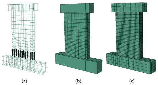
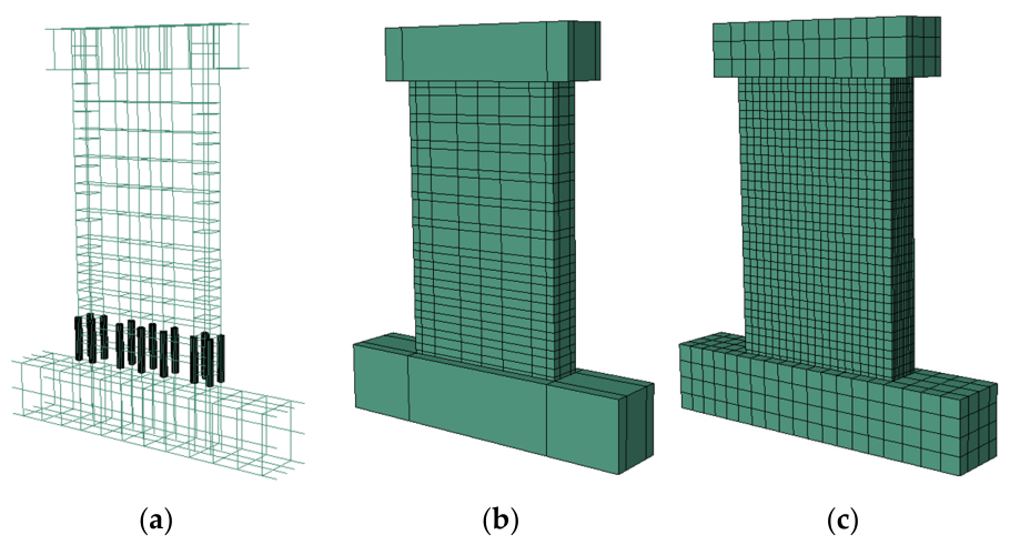
The grid size affects both computational efficiency and the resolution of localized damage. The adopted mesh consists of 100 mm elements for the ground and loading beams, 50 mm elements in the wall height and width directions, 20 mm elements through the wall thickness, 20 mm elements for the sleeve and grout, and 50 mm elements for reinforcement. The mesh was selected according to the connection geometry and the expected localization of damage. Because no independent mesh-refinement calculations were performed, mesh convergence is not claimed. Accordingly, local damage contours are interpreted as qualitative indicators, whereas global quantities such as peak load and displacement are considered more suitable for comparison among the investigated cases. Figure 2 shows the finite element model for thermal analysis of prefabricated shear walls.
Figure 2.
Finite element model for thermal analysis of prefabricated shear wall: (a) rebar; (b) concrete shear wall; (c) model meshing.
2.3.2. Material Properties
- Thermal Parameters of Materials
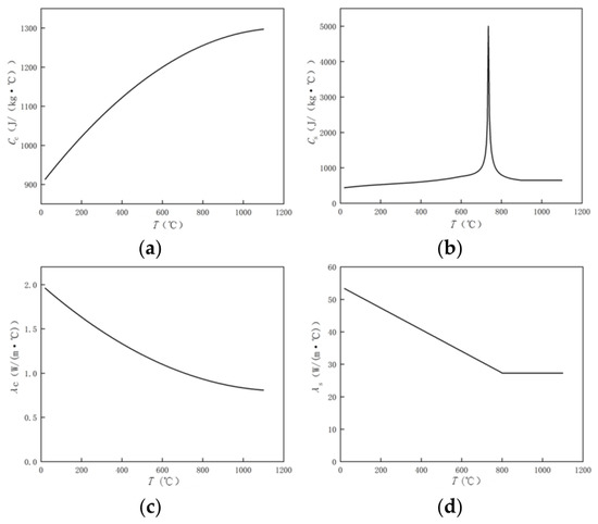
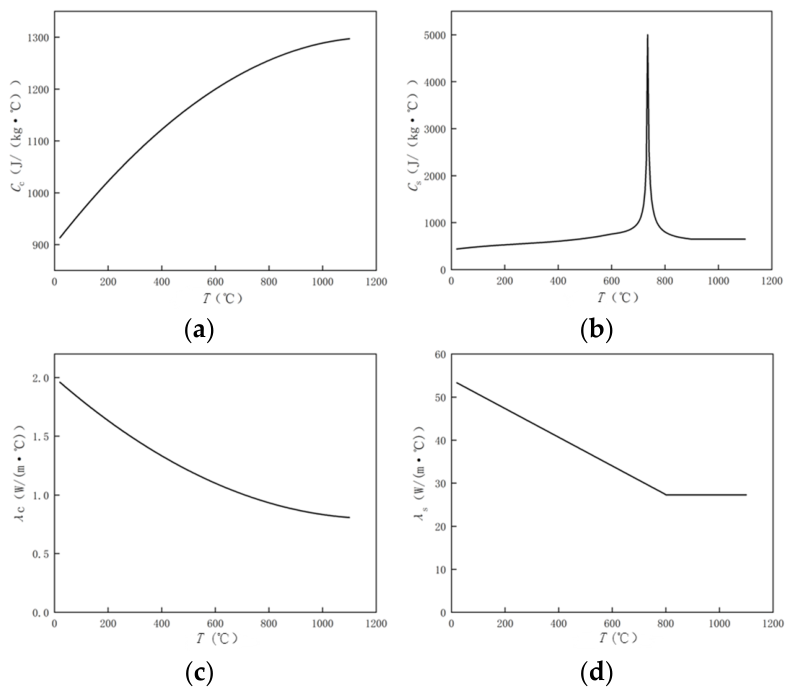
The thermal properties of materials directly affect the temperature field distribution of building structures during and after a fire. Existing research [24,27,28,29] indicates that the thermal properties of sleeve grouting materials differ from those of conventional concrete. Therefore, the experimentally derived thermal capacity and thermal conductivity relationships for sleeve grouting materials reported by Xue et al. [24] are adopted in this study. The tests covered temperatures from 20 to 900 °C, and the temperature-dependent thermal properties are expressed as follows:
For concrete and steel, the temperature-dependent thermal parameters are calculated using the relationships adopted in the original model and recommended by the European Code [30]. For sleeve grouting material, the temperature-dependent relationships reported by Xue et al. [24] are adopted separately to account for its distinct thermal response. Figure 3 shows the thermal parameters of materials.
Figure 3.
Thermal parameters of materials: (a) specific heat of concrete and grouting material; (b) specific heat of steel; (c) thermal conductivity of concrete and grouting material; (d) thermal conductivity of steel.
- 2.
- Constitutive Relationship of Materials
At room temperature, the constitutive behavior of concrete is calculated based on the constitutive model provided in the Code for Design of Concrete Structures [31]. For sleeve grouting material, Xue et al. [24] reported the temperature-dependent compressive strength and proposed the following residual compressive-strength relationship:
The above relationship represents the experimentally established temperature dependence of the compressive strength of sleeve grout [24]. A complete temperature-dependent tensile, fracture energy, unloading/reloading, and damage parameter set for the specific grout used in JLQ3 is not available from the present experimental basis. Therefore, no additional unsupported nonlinear parameters are introduced, and the numerical results are interpreted primarily through the relative changes among the investigated cases.
For reinforcement steel, the present mechanical analysis retains the room temperature constitutive relationship after the thermal analysis. This treatment is a modeling simplification rather than a general assumption that the residual properties of reinforcement are unchanged after fire. Published investigations indicate that the residual elastic modulus, yield strength, and ultimate strength of reinforcing steel after heating and cooling depend on the peak temperature, steel grade, thermal history, and cooling condition [32]. Because no independent residual property test data for the HRB400 reinforcement in JLQ3 are available in the present study, a temperature- and cooling-dependent residual constitutive model is not introduced. Accordingly, the influence of reinforcement residual properties is included as a modeling uncertainty when interpreting the post-fire numerical results.
2.3.3. Interaction Relationship
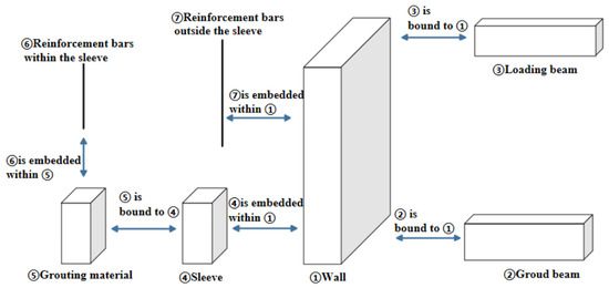
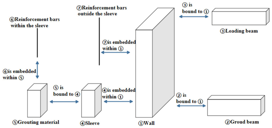
After fire exposure, degradation of the reinforcement–grout bond may lead to pull-out and slip. Therefore, the reinforcement–grout interface is represented by nonlinear spring elements in the post-fire mechanical model. The spring response is described conceptually by a force–slip relationship characterized by the initial stiffness Ks, peak interface resistance Fs,max, characteristic slip s1, post-peak stiffness Ks,post, residual resistance Fs,res, and ultimate slip su. The failure condition is reached when the prescribed ultimate-slip criterion is satisfied. The sleeve–grout interface is represented by a tied constraint, while the sleeve and reinforcement outside the sleeve are embedded in the surrounding concrete. The parameters of the spring model should be calibrated against post-fire sleeve connection tests or directly traceable experimental data; no universal values are assigned in the present study because independent interface calibration data for the exact sleeve system are unavailable. Consequently, the spring representation is used to describe the degradation mechanism qualitatively, and its quantitative influence is not separated from the other post-fire degradation mechanisms. Figure 4 shows the thermal interaction relationships in finite element model of prefabricated shear walls.
Figure 4.
Thermal interaction relationships in finite element model of prefabricated shear walls.
2.3.4. Boundary Conditions and Loading Mode
In temperature field analysis, considering that walls in actual fires are often exposed to fire on one side, one side of the wall is defined as the fire-exposed surface, while the other side is defined as the unexposed surface, as shown in Figure 5. The convective heat transfer coefficient of the fire-exposed surface is 25 W/(m2·°C), the comprehensive thermal radiation coefficient is 0.5, and the convective heat transfer coefficient of the unexposed surface is 9 W/(m2·°C). The absolute zero temperature is −273.15 °C, the Boltzmann constant is 5.67 × 10⁻⁸ (W/m2·K), and the initial temperature is 20 °C. These boundary conditions are set as close as possible to actual fire scenarios, providing a guarantee for accurately simulating the temperature field of walls.
Figure 5.
Schematic diagram of single-side fire exposure model.
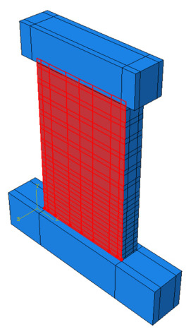
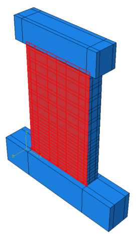
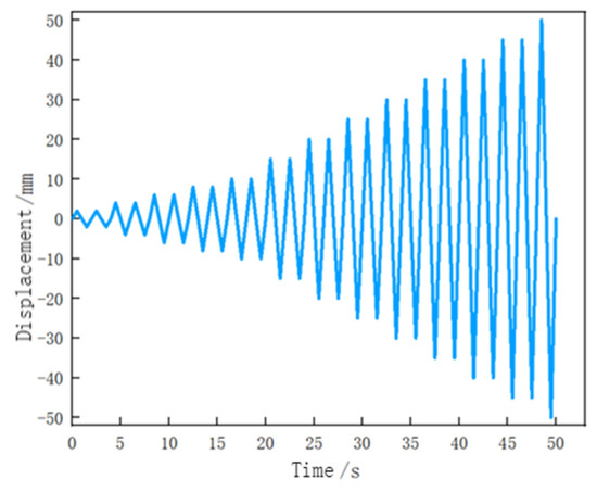
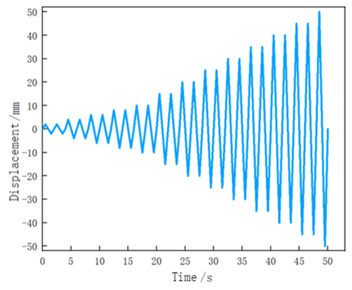
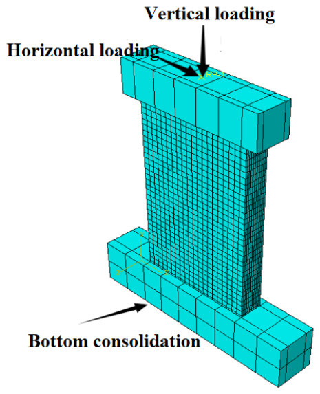
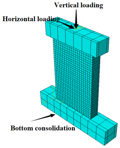
In the pseudo-static analysis, a reference point RP-1 is established at the top of the loading beam and coupled with the top surface of the loading beam as the loading point. The simulation is conducted in two analysis steps. Step 1: A vertical force in the form of a concentrated force F is applied to RP-1 to simulate the bearing capacity of the wall under normal stress conditions, which remains constant until the end of Step 2. Step 2: A horizontal force is applied to RP-1 in the form of displacement-controlled loading to simulate the stress and deformation characteristics of the wall during reciprocal vibration during an earthquake. The displacement-controlled loading system is shown in Figure 6.
Figure 6.
Horizontal displacement loading protocol.
When the wall load drops to 85% of the peak load of the shear wall, it is assumed that the wall has been damaged. The boundary conditions are set to be fixed at the bottom of the ground beam, and the degrees of freedom of the wall are constrained to ensure that the wall displaces only along the loading direction. The specific constraints are shown in Figure 7.
Figure 7.
Schematic diagram of model loading and boundary conditions.
2.4. Model Validation
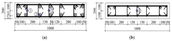
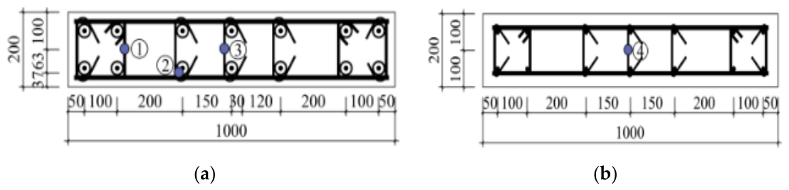
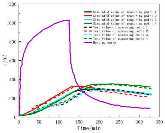
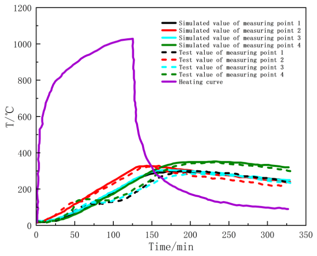
To verify the accuracy of the model, this study conducted a simulation analysis on the JLQ3 test specimen reported by Zheng Jiahao et al. [18]. The experimental temperature curve was used as the temperature-rise history, and the validation case adopted four-sided fire exposure for 113 min, consistent with the available test configuration. Four thermocouples were used to compare the calculated and measured temperatures at representative locations in and around the sleeve region. Four thermocouples are embedded in the wall. The specific arrangement of thermocouples is shown in Figure 8.
Figure 8.
Layout of temperature measurement points for specimen JLQ3(Unit: mm): (a) Cross-sectional view at a wall height of 120 mm; (b) cross-sectional view at a wall height of 800 mm. Numbers ①, ②, ③, and ④ represent the positions of four temperature measurement points, respectively.
Table 1 and Figure 9 present the comparison between the simulated and experimental temperature histories. The maximum temperature errors at the four measuring points are 1%, 1%, 6%, and 1%, respectively; the maximum absolute error is therefore 6%. The simulated curves also reproduce the overall temperature-rise trend at the four locations. These quantitative results provide the primary numerical verification of the thermal field.
Table 1.
Maximum temperature at different measuring points and times to reach the maximum temperature.
Figure 9.
Comparison of temperature curves at measuring points of shear wall specimens.
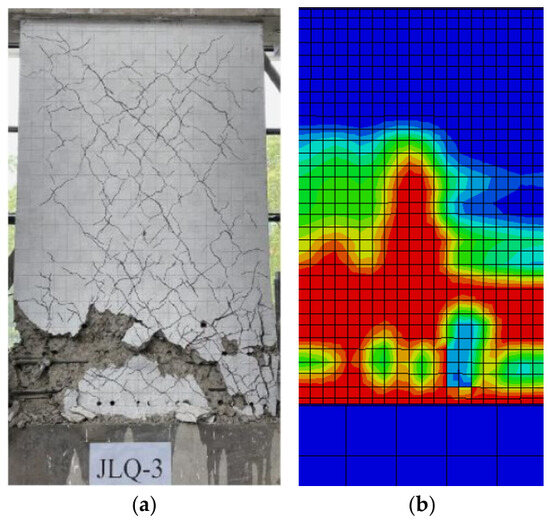
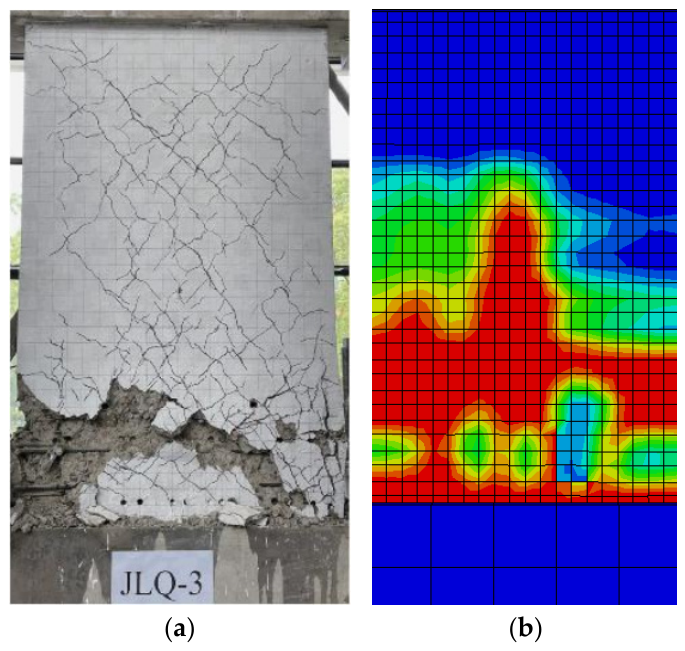
The simulated failure mode is consistent with the experimental observations, with pronounced damage concentrated at the wall corner, horizontal joint, and region above the sleeve. The agreement in damage distribution indicates that the model can reproduce the principal post-fire failure characteristics of the sleeve-grouted prefabricated shear wall.
The validation specimen was subjected to four-sided fire, whereas the subsequent parametric analysis considers one-sided fire exposure. Because the two fire conditions produce different temperature gradients, the validated four-sided-fire model is used to establish the numerical modeling framework, while the one-sided-fire results are evaluated within the corresponding thermal boundary conditions.
Figure 10 shows a comparison between the component failure mode and the damage contour map. It can be clearly seen from the damage distribution map that the concrete at the wall corner, above the sleeve area, and at the horizontal joint position of the component is significantly damaged, and this is similar to the overall trend of the experimental results. This indicates that the established model not only accurately simulates the temperature field but also has high credibility in reflecting the structural failure mode.
Figure 10.
Comparison of failure phenomena of shear wall specimens: (a) destruction phenomenon; (b) damage distribution map.
The numerical model incorporates the temperature-dependent thermal and compressive-strength relationships of sleeve grouting material [24] and the post-fire interface behavior reported for grouted sleeve connections [25,26]. The temperature-field comparison gives a maximum error of 6%, while the simulated damage distribution is consistent with the experimental failure pattern. These results provide a basis for the subsequent parametric analysis.
2.5. Scope and Applicability of Parameter Analysis
The parameter analysis considers the fire duration, axial compression ratio, aspect ratio, and longitudinal reinforcement diameter under a consistent modeling framework. One-sided fire exposure is adopted as the thermal boundary condition for all parametric cases. The axial compression ratio varies from 0.1 to 0.5, and the response variation around 0.3 is characterized as a transition within the investigated range.
2.6. Parameter Design
To investigate the impact of fire on the seismic performance of prefabricated shear walls with sleeve grouting connections, a total of 18 specimens were designed for analysis based on literature [18]. Parameters such as fire exposure duration (five specimens), axial compression ratio (five specimens), aspect ratio (five specimens), and longitudinal reinforcement diameter (three specimens) were considered. Specific design parameters are shown in Table 2.
Table 2.
Test specimen parameters.
3. Simulation Results and Analysis
3.1. Failure Modes Analysis
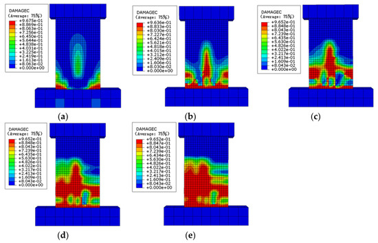
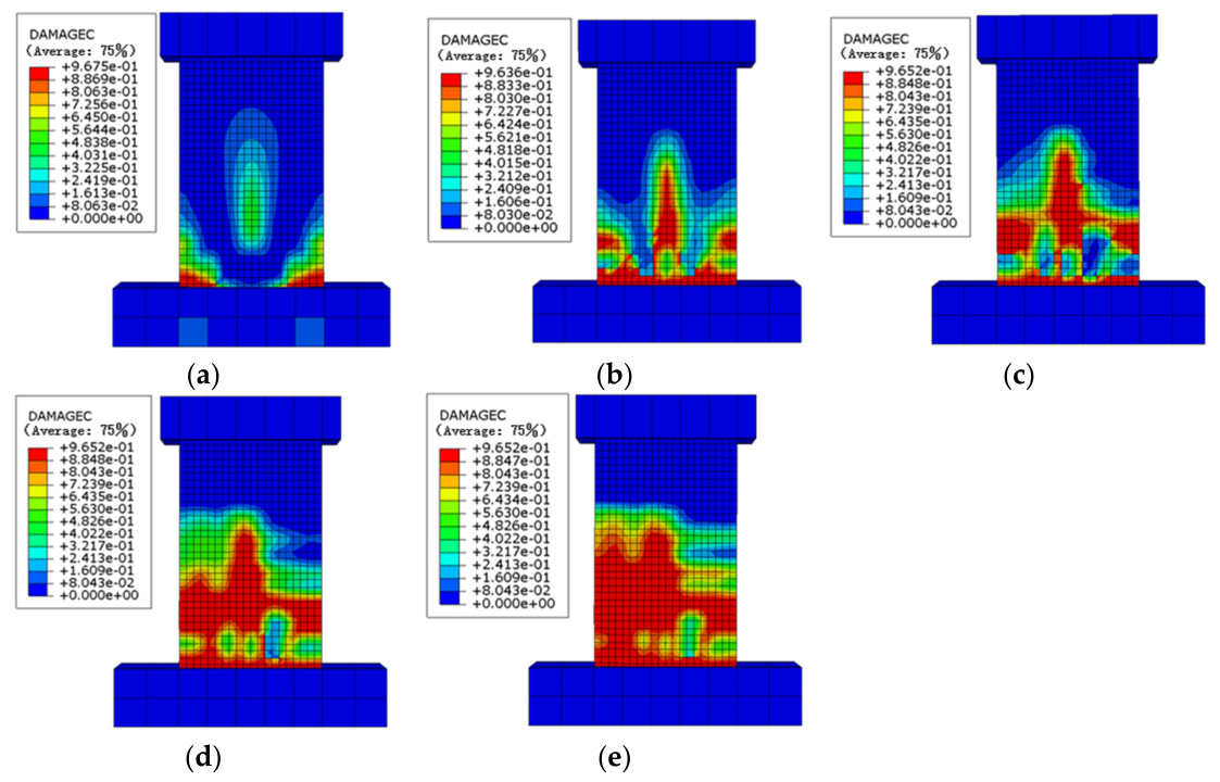
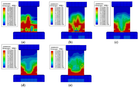
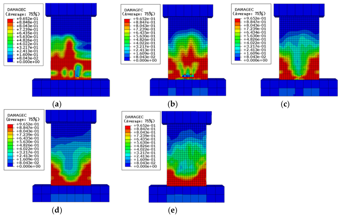
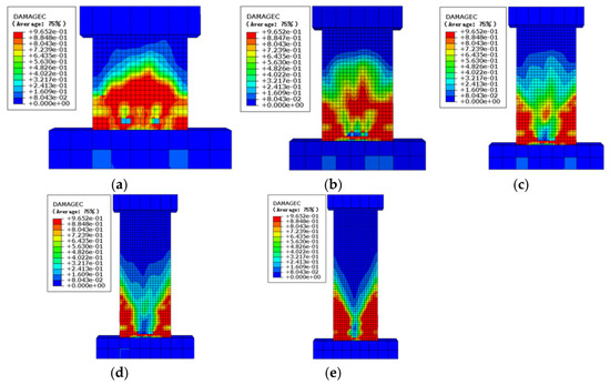
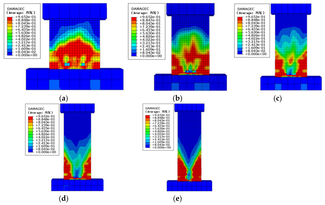
Figure 11, Figure 12 and Figure 13 depict the failure modes of prefabricated shear walls under horizontal reciprocal loads, considering varying fire exposure durations, axial compression ratios, and aspect ratios. In the figures, the blue areas represent undamaged concrete, while the red areas indicate damaged concrete.
Figure 11.
Failure modes of prefabricated shear walls with different fire durations: (a) W1; (b) W2; (c) W3; (d) W4; (e) W5.
Figure 12.
Failure modes of prefabricated shear walls with different axial compression ratios: (a) W6; (b) W7; (c) W8; (d) W9; (e) W10.
Figure 13.
Failure modes of prefabricated shear walls with different aspect ratios: (a) W11; (b) W12; (c) W13; (d) W14; (e) W15.
The failure modes of prefabricated shear walls subjected to different durations of fire under horizontal reciprocal loading are shown in Figure 11. The failure modes of sleeve-grouted prefabricated shear walls under different durations of fire are similar, and as the duration of fire increases, the failure area and damage degree of the wall concrete gradually increase. At room temperature, the damage of sleeve-grouted prefabricated shear walls first occurs at the corners of the wall and gradually extends to the middle of the wall, exhibiting typical bending-shear failure characteristics, which are consistent with the failure modes of traditional cast-in-place shear walls. Compared with room temperature, the damage of sleeve-grouted prefabricated shear walls after fire is more severe, mainly concentrated in the horizontal joints and the area above the sleeves. This is because the sleeves have a certain restraining effect on the surrounding concrete. Under fire, the mechanical properties, such as the strength and elastic modulus of the concrete material, are severely weakened, and the restraining effect of the sleeves on the concrete decreases, leading to damage concentrated in these areas. Moreover, as the duration of fire increases, the damage area gradually extends upward until the specimen basically loses its load-bearing capacity.
The failure modes of prefabricated shear walls with different axial compression ratios under horizontal reciprocal loads are shown in Figure 12. Different axial compression ratios have a significant impact on the failure modes of prefabricated shear walls with sleeve grouting connections after fire. As the axial compression ratio increases, the damage to the sleeve-grouted prefabricated shear walls gradually progresses from the bottom of the wall upwards. When the axial compression ratio is relatively low, as in specimens W6 and W7, the damage is characterized by concrete crushing at the horizontal joints, with horizontal through-penetrating and diagonal damage forming above the sleeve area, exhibiting a typical bending-shear failure mode. However, when the axial compression ratio is relatively high, damage to the specimens is mainly characterized by concrete crushing in the sleeve area of the wall, with “V”-shaped cracks forming above the sleeve area and damage occurring at the wall corners, similar to the bending failure mode of cast-in-place shear walls. This is because the sleeve grouting connections enhance the rigidity of the bottom of the wall, resulting in the upward shift in damage.
The failure modes of prefabricated shear walls with different aspect ratios under horizontal reciprocal loads are shown in Figure 13. Different aspect ratios also have a significant impact on the failure modes of prefabricated shear walls with sleeve grouting connections after fire. As the aspect ratio increases, the failure mode of the specimens gradually transitions from shear failure to bending failure. Under horizontal reciprocal loads, the failure mode of specimen W11 with an aspect ratio of 1.0 is characterized by cracks spreading diagonally from the middle of the wall top to above the sleeve area, with concrete crushing at the bottom of the wall, which is a typical oblique compression failure. Specimens W12 and W13, with aspect ratios of 1.6 and 2.0, mainly exhibit bending-shear failure modes. Specimens W14 and W15, with aspect ratios of 2.5 and 3.0, mainly exhibit bending failure modes, with concrete crushing at the foot and diagonal cracks.
In summary, the extension of fire exposure time will exacerbate wall damage and alter the distribution of damage. Changes in the axial compression ratio will cause the failure mode of sleeve-grouted connection prefabricated shear walls to gradually shift from flexural-shear failure to flexural failure, with the failure location moving upwards. An increase in the aspect ratio will promote a transition from shear failure to flexural failure. These patterns of failure mode changes are of great significance for a deeper understanding of the mechanical properties of sleeve-grouted connection prefabricated shear walls after fire.
3.2. Hysteresis Curve
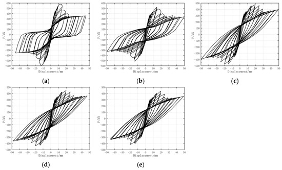
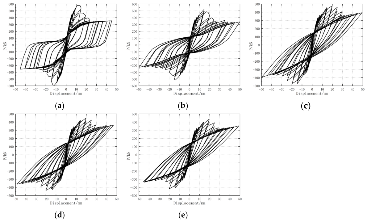
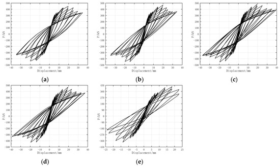
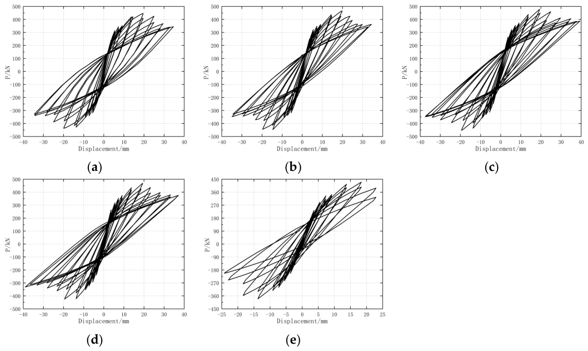
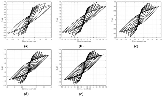
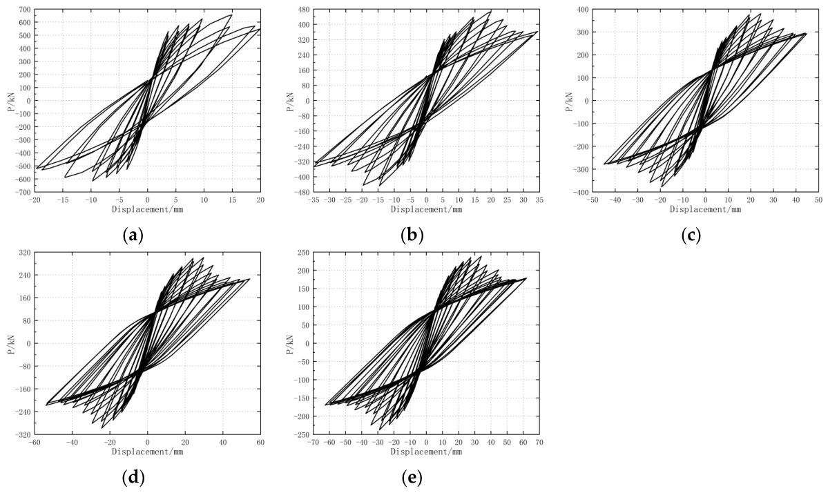
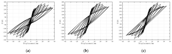
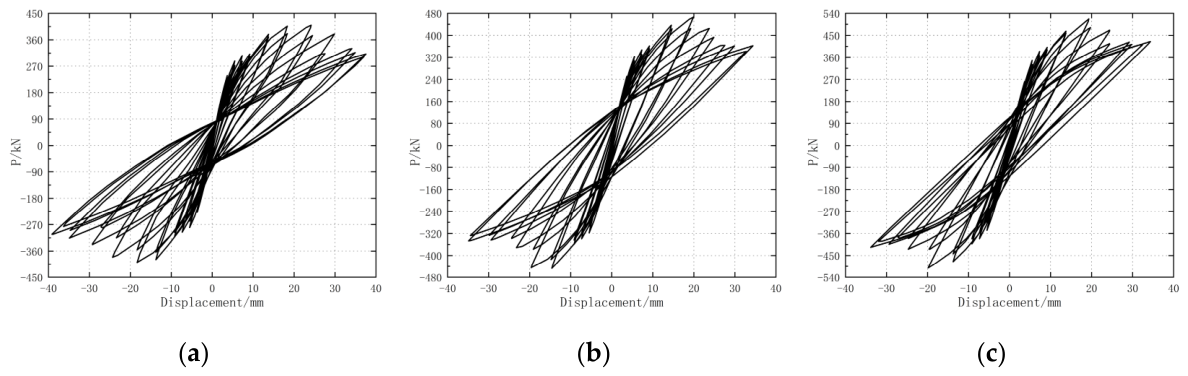
The hysteresis curve, obtained from horizontal reciprocating load tests, represents the load–displacement curve and serves as a primary indicator for analyzing and evaluating the seismic performance of structures. Here, F denotes the horizontal load, while ∆ signifies the horizontal displacement. Figure 14, Figure 15, Figure 16 and Figure 17 illustrate the hysteresis curves of prefabricated shear walls under horizontal reciprocating loads, considering varying fire exposure durations, axial compression ratios, aspect ratios, and longitudinal bar diameters.
Figure 14.
Hysteretic curves of prefabricated shear walls with different fire durations: (a) W1; (b) W2; (c) W3; (d) W4; (e) W5.
Figure 15.
Hysteretic curves of prefabricated shear walls with different axial compression ratios: (a) W6; (b) W7; (c) W8; (d) W9; (e) W10.
Figure 16.
Hysteretic curves of prefabricated shear walls with different aspect ratios: (a) W11; (b) W12; (c) W13; (d) W14; (e) W15.
Figure 17.
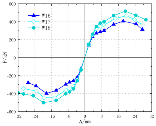
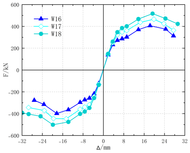
Hysteretic curves of prefabricated shear walls with different longitudinal reinforcement diameters: (a) W16; (b) W17; (c) W18.
Figure 14 illustrates the hysteresis curves of prefabricated shear walls subjected to varying durations of fire exposure under horizontal reciprocal loading. At room temperature, the hysteresis curves of prefabricated shear walls with sleeve grouting connections are full and predominantly arcuate, indicating good seismic performance of the walls. As the duration of fire exposure increases, the mechanical properties of steel and concrete materials in the walls deteriorate. Consequently, significant changes are observed in the hysteresis curves of these walls. Their bearing capacity gradually decreases with increasing fire exposure duration, and the area of the hysteresis loop also diminishes. This suggests that the energy dissipation capacity of prefabricated shear walls with sleeve grouting connections is severely affected by fire. The longer the fire exposure duration, the weaker their energy dissipation capacity becomes. For instance, when the fire exposure duration increases from 30 min to 120 min, the area of the hysteresis curve decreases by approximately 30%. The results clearly demonstrate the weakening effect of fire on the energy dissipation capacity of structures.
Figure 15 illustrates the hysteresis curves of prefabricated shear walls with different axial compression ratios under horizontal reciprocating loads. When the axial compression ratio of the specimens ranges from 0.1 to 0.4, there is no significant change in the hysteresis curves after being exposed to fire for 90 min. However, when the axial compression ratio is 0.5, the area of the hysteresis curve of the specimens significantly decreases, indicating that an excessively high axial compression ratio can degrade the energy dissipation capacity of the components, which is detrimental to the safety of the structure.
Figure 16 illustrates the hysteresis curves of prefabricated shear walls with varying aspect ratios under horizontal reciprocal loading. The aspect ratio of the specimens has minimal influence on the shape of the hysteresis curves of post-fire sleeve-grouted connection prefabricated shear walls, with all specimens exhibiting an “S” shape. However, as the aspect ratio of the specimens increases, the hysteresis curves of post-fire sleeve-grouted connection prefabricated shear walls gradually become “flattened”. This is due to the decrease in lateral stiffness and shear bearing capacity of the sleeve-grouted connection prefabricated shear walls with an increasing aspect ratio, leading to changes in the shape of the hysteresis curves.
Figure 17 illustrates the hysteresis curves of prefabricated shear walls with varying longitudinal bar diameters under horizontal reciprocal loads. As the diameter of the longitudinal bar increases, the pinching effect of the hysteresis curve gradually decreases. This is because the bond performance between the steel bar, concrete, and grouting material is positively correlated with the steel reinforcement ratio. The larger the diameter of the steel bar, the better the bond performance, resulting in a fuller hysteresis curve for the specimen. Conversely, the smaller the diameter of the steel bar, the less steel content in the specimen, leading to a decrease in the stiffness and bearing capacity of the wall. Therefore, the hysteresis curve of the specimen becomes flatter.
In summary, an increase in fire exposure duration reduces the energy dissipation capacity of the structure; an excessively high axial compression ratio is detrimental to the structure’s energy dissipation; the aspect ratio primarily affects the shape of the hysteresis curve, making it flatter as the aspect ratio increases; the diameter of the longitudinal reinforcement is related to the fullness of the hysteresis curve, with a larger diameter of longitudinal reinforcement resulting in a fuller hysteresis curve. These factors interact and collectively affect the seismic performance of prefabricated shear walls with sleeve grouting connections after fire.
3.3. Skeleton Curve
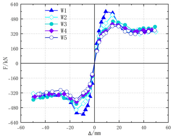
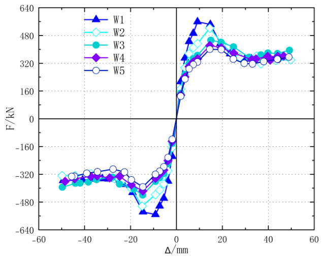
The skeleton curve is the trajectory curve obtained by connecting the maximum load points of the first cycle of loading in the same direction on the load–displacement curve. It can visually reflect the relationship between the deformation capacity and load-bearing capacity of the structure. Figure 18, Figure 19, Figure 20 and Figure 21 show the skeleton curves of prefabricated shear walls under horizontal reciprocal loading, considering different fire exposure durations, axial compression ratios, aspect ratios, and longitudinal bar diameters.
Figure 18.
Skeleton curve of prefabricated shear wall with different fire durations.
Figure 19.
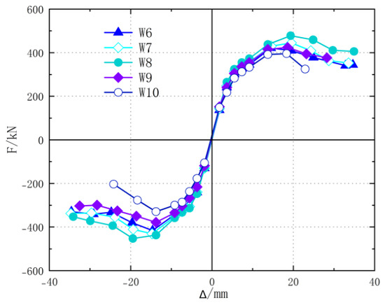
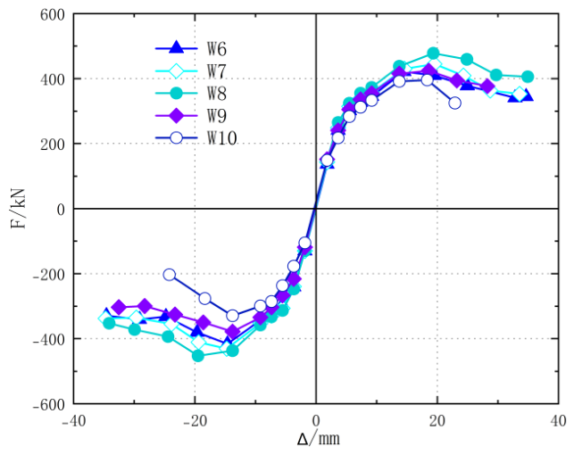
Skeleton curves of prefabricated shear walls with different axial compression ratios.
Figure 20.
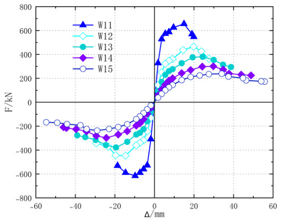
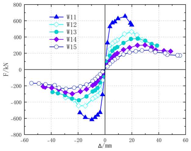
Skeleton curves of prefabricated shear walls with different height–width ratios.
Figure 21.
Skeleton curve of prefabricated shear wall with different longitudinal reinforcement diameters.
Figure 18 illustrates the skeleton curves of prefabricated shear walls subjected to different fire durations under horizontal reciprocal loads. Compared to specimens under normal temperature conditions, the shear bearing capacity of prefabricated shear walls with sleeve grouting connections that have been subjected to fire is significantly reduced. The longer the fire exposure time, the worse their bearing capacity becomes. Additionally, fire has a significant impact on the initial stiffness of the walls, with the ascending segment of the skeleton curve gradually slowing down as the fire exposure time increases. This is because fire causes concrete to soften, and the longer the fire exposure time, the more severe the softening of concrete becomes, which macroscopically manifests as a lower slope of the skeleton curve.
Figure 19 illustrates the skeleton curves of prefabricated shear walls with different axial compression ratios under horizontal reciprocal loads. Different axial compression ratios have varying impacts on the skeleton curves of prefabricated shear walls with grouted sleeve connections after fire. When the axial compression ratio of the specimen is between 0.1 and 0.3, the shear bearing capacity of the specimen increases with an increase in the axial compression ratio; when the axial compression ratio of the specimen is between 0.3 and 0.5, the shear bearing capacity of the specimen decreases with an increase in the axial compression ratio. Among them, specimen W10 rapidly declines after reaching the peak load, and its plastic displacement is much lower than that of other components. This is because the increase in axial pressure reduces the deformation capacity of the component under horizontal reciprocal loads, which is particularly evident in the descending segment.
Figure 20 illustrates the skeleton curves of prefabricated shear walls with varying aspect ratios under horizontal reciprocal loading. Different aspect ratios significantly affect the skeleton curves of prefabricated shear walls with grouted sleeve connections after fire. As the aspect ratio increases, the slope of the elastic segment of the specimen’s skeleton curve gradually decreases. This is due to the negative correlation between the initial lateral stiffness of the wall and its height; the taller the wall, the lower its initial stiffness. From the figure, it is evident that as the aspect ratio increases, the horizontal bearing capacity of the specimens significantly decreases. For instance, the peak bearing capacity of specimen W11 is approximately three times that of specimen W15. Additionally, the skeleton curve of specimen W11 drops rapidly after reaching the peak load, whereas the peak points of the other specimens shift backward to varying extents as the aspect ratio increases, and the descending segment becomes gentler.
Figure 21 illustrates the skeleton curves of prefabricated shear walls with varying longitudinal bar diameters under horizontal reciprocal loading. The overall trend of the skeleton curves for specimens with different longitudinal bar diameters is essentially consistent, and they all exhibit a downward trend after the horizontal bearing capacity reaches its peak. This trend gradually becomes gentler as the longitudinal bar diameter increases. The larger the longitudinal bar diameter of the specimen, the better its horizontal bearing capacity. For instance, the straight-line segment of the skeleton curve for specimen W18 is significantly higher than that for W17 and W16, indicating that increasing the longitudinal bar diameter can effectively enhance the normal service limit of post-fire sleeve-grouted connection prefabricated shear walls.
In summary, an increase in fire exposure duration reduces the structural load-bearing capacity and initial stiffness; the axial compression ratio has varying impacts on the structural shear load-bearing capacity and deformation capacity across different ranges; an increase in aspect ratio decreases the initial stiffness and horizontal load-bearing capacity of the structure, but there is a certain pattern in the changes at the peak point and during the descending phase; an increase in the diameter of longitudinal reinforcement can enhance the horizontal load-bearing capacity. It is necessary to comprehensively consider the impact of these factors on the skeleton curve to ensure the safety and reliability of the structure after a fire.
3.4. Bearing Capacity and Ductility
The characteristic points of the skeleton curve are defined as the yield point (Fy, Dy), peak point (Fm, Dm), and failure point (Fu, Du). The equivalent-energy method is used to determine the yield point. An idealized elastic–perfectly plastic curve is constructed so that the area enclosed by the idealized curve and the actual skeleton curve up to the target deformation is equal. The intersection of the elastic branch of the idealized curve with the horizontal line through Fy defines the equivalent yield point, and the corresponding displacement is Dy. The displacement ductility coefficient is then defined as μ = Du/Dy.
The peak point is defined by the maximum horizontal load Fm and its corresponding displacement Dm. The failure point is defined on the descending branch at Fu = 0.85Fm, with the corresponding displacement denoted by Du. The same definitions and the same equivalent-energy procedure are applied to all numerical specimens to ensure consistency of the ductility comparison.
The damage displacement Du is taken as the displacement corresponding to when the peak load Fm drops to 85%.
Table 3, Table 4, Table 5 and Table 6, respectively, present the characteristic points and ductility of the load-bearing capacity of prefabricated shear walls under different fire exposure durations, axial compression ratios, aspect ratios, and longitudinal bar diameters.
Table 3.
Bearing capacity and ductility coefficient of prefabricated shear walls with different fire durations.
Table 4.
Bearing capacity and ductility coefficient of prefabricated shear walls with different axial compression ratios.
Table 5.
Bearing capacity and ductility coefficient of prefabricated shear walls with different aspect ratios.
Table 6.
Bearing capacity and ductility coefficient of prefabricated shear walls with different longitudinal reinforcement diameters.
Table 3 presents the characteristics of the bearing capacity and ductility of prefabricated shear walls that are subjected to different durations of fire exposure. Different durations of fire exposure have varying degrees of impact on the bearing capacity and ductility of post-fire sleeve-grouted connection prefabricated shear walls. Compared to unexposed components, the yield load, peak load, and failure load of exposed components show a downward trend, while the yield displacement, peak displacement, and failure displacement increase overall. The longer the fire exposure time, the greater the reduction in the bearing capacity of the specimens. For example, after being exposed to fire for 30, 60, 90, and 120 min, the peak load and failure load of the specimens decreased by 14.50%, 15.84%, 21.40%, and 23.70%, respectively. At the same time, the ductility coefficients of the specimens decreased by 7.98%, 12.17%, 15.21%, and 20.15%, respectively, indicating that the longer the fire exposure time, the faster the ductility coefficient of the specimens decreases, and the weaker their deformation capacity becomes.
Table 4 presents the characteristics of bearing capacity and ductility of prefabricated shear walls with different axial compression ratios. Different axial compression ratios also have varying impacts on the bearing capacity and ductility of prefabricated shear walls with sleeve grouting connections after fire. When the axial compression ratio of the test specimen is between 0.1 and 0.3, the yield load, yield displacement, peak load, and failure load of the prefabricated shear wall with sleeve grouting connections after fire increase with the increase in axial compression ratio, but the peak displacement decreases with the increase in axial compression ratio. When the axial compression ratio is between 0.3 and 0.5, the characteristic values of the bearing capacity of the prefabricated shear wall with sleeve grouting connections after fire decrease with the increase in the axial compression ratio. In addition, as the axial compression ratio increases, the ductility of the test specimen shows a trend of increasing first and then decreasing. When the axial compression ratio is 0.3, the ductility of the component is the best.
Table 5 presents the characteristics of bearing capacity and ductility of prefabricated shear walls with different aspect ratios. Different aspect ratios have varying degrees of impact on the bearing capacity and ductility of sleeve-grouted connection prefabricated shear walls after fire. After being exposed to fire for 90 min, the yield load, peak load, and failure load of sleeve-grouted connection prefabricated shear walls show an overall downward trend as the aspect ratio increases. Meanwhile, the yield displacement, peak displacement, and failure displacement exhibit an overall upward trend with increasing aspect ratio. As the aspect ratio increases, the ductility coefficients of various components initially decline rapidly and then gradually slow down. For instance, compared to W11, the ductility of specimens W12, W13, W14, and W15 decreases by 18.40%, 22.57%, 29.86%, and 30.56%, respectively, indicating that the ductility of sleeve-grouted connection prefabricated shear walls after fire decreases with an increasing aspect ratio.
Table 6 presents the characteristics of bearing capacity and ductility of prefabricated shear walls with different diameters of longitudinal bars. Different diameters of longitudinal bars have varying degrees of impact on the bearing capacity and ductility of post-fire sleeve-grouted connection prefabricated shear walls. After fire, the yield load, yield displacement, peak load, and failure load of the sleeve-grouted connection prefabricated shear walls increase overall with the increase in the diameter of the longitudinal bars, while the trends in peak displacement and failure displacement are not obvious. As the diameter of the longitudinal bars increases, the ductility coefficient of each specimen decreases, with the ductility coefficients of W17 and W18 decreasing by 5.24% and 10.89%, respectively, compared to W16.
In summary, fire duration, axial compression ratio, aspect ratio, and longitudinal bar diameter significantly affect the bearing capacity and ductility of post-fire sleeve-grouted prefabricated shear walls. For fire durations of 30, 60, 90, and 120 min, the simulated peak-load reductions are 14.50%, 15.84%, 21.40%, and 23.70%, respectively, while the corresponding ductility reductions are 7.98%, 12.17%, 15.21%, and 20.15%. For the axial compression ratio series, the ductility coefficient increases from 2.23 at 0.1 to 2.76 at 0.3 and then decreases to 2.01 at 0.5. For aspect ratios of 1.0, 1.6, 2.0, 2.5, and 3.0, the ductility coefficients are 2.88, 2.35, 2.23, 2.02, and 2.00, respectively. The results indicate distinct transition characteristics within the investigated parameter ranges.
3.5. Energy Consumption Capacity
The energy dissipation capacity of a specimen is often measured by the area enclosed by a hysteresis loop, which is usually represented by the energy dissipation coefficient E. The calculation formula is as follows:
Among them, S(abc+cda) represents the area of the hysteresis loop, and S(Δodf+Δobe) represents the areas of ∆odf and ∆obe.
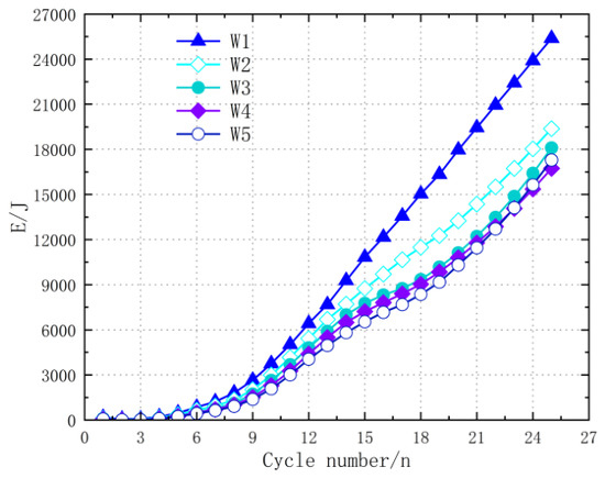
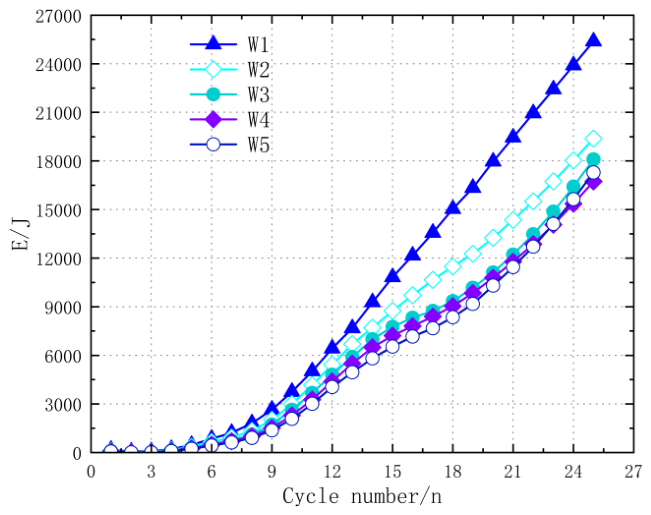
Figure 22 shows the energy dissipation curves of prefabricated shear walls with different fire durations under horizontal reciprocating loads. The fire did not have a significant impact on the cumulative energy consumption trend of the sleeve-grouting-connected assembled shear wall. In the early stage of horizontal loading, the energy consumption of the components under fire and those without fire were basically the same, and there was no significant fluctuation. As the number of horizontal loading cycles increased, the cumulative energy consumption of each specimen showed an exponential increase trend. However, the cumulative energy consumption of the sleeve grouting-connected prefabricated shear wall after being exposed to fire is significantly lower than that of the ambient temperature specimens, and the longer the fire exposure time, the worse the cumulative energy consumption level of the specimens, indicating that the fire has reduced the overall energy consumption capacity of the specimens.
Figure 22.
Energy dissipation curves of prefabricated shear walls with different fire durations.
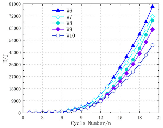
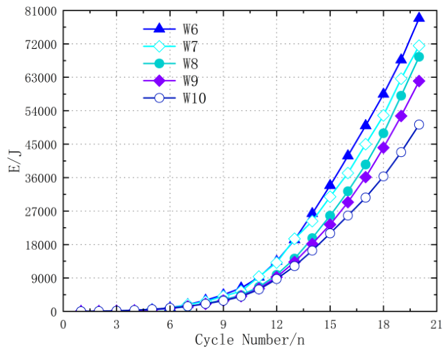
Figure 23 shows the energy dissipation curves of prefabricated shear walls with different axial compression ratios under horizontal reciprocating loads. The sleeve-grouted connection assembled shear walls with different axial compression ratios did not show a significant increase in energy dissipation due to being in the elastic stage, but as the number of hysteresis cycles increased, the specimens entered the plastic yield stage and energy dissipation increased significantly. Under the same level of load, the energy dissipation capacity of each specimen, from highest to lowest, is W6, W7, W8, W9, W10. Among them, the final energy dissipation of specimen W6 is 1.57 times that of W10, indicating that a high axial compression ratio will have an adverse effect on the energy dissipation capacity of sleeve-grouted connected prefabricated shear walls after a fire. The larger the axial compression ratio, the weaker the energy dissipation capacity of the specimen.
Figure 23.
Energy dissipation curves of prefabricated shear walls with different axial compression ratios.
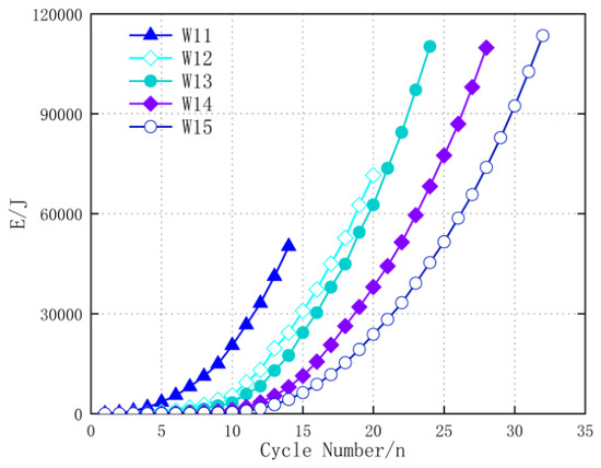
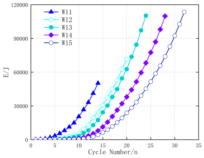
Figure 24 shows the energy dissipation curves of prefabricated shear walls with different aspect ratios under horizontal reciprocating loads. Similar to specimens with different axial compression ratios, specimens with different aspect ratios did not show a significant increase in energy dissipation during the elastic stage. However, as the number of hysteresis cycles increased, the specimens entered the plastic yield stage and energy dissipation increased significantly. Under the same horizontal load, the smaller the aspect ratio of the specimen, the stronger its energy dissipation capacity. This is because when reaching the same horizontal displacement, the smaller the aspect ratio, the greater the horizontal load required for the component, and therefore the greater the energy dissipation. In addition, there is no significant difference in the final cumulative energy consumption of specimens W8–W10 with a large aspect ratio, but it is much higher than that of specimens W6 and W7. On the one hand, the increase in aspect ratio leads to an increase in the plastic displacement of the specimens, and the overall energy consumption capacity will also increase. On the other hand, the increase in aspect ratio will significantly reduce the bearing capacity, thereby reducing the overall energy consumption capacity of the component. Therefore, there is a phenomenon of no significant difference in the final energy consumption of specimens with a large aspect ratio.
Figure 24.
Energy dissipation curves of prefabricated shear walls with different aspect ratios.
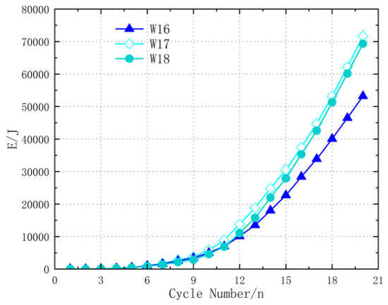
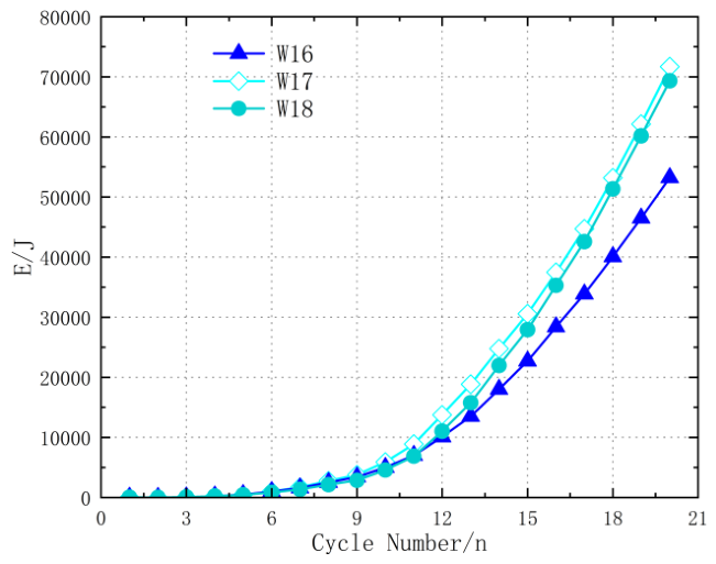
Figure 25 shows the energy dissipation curves of prefabricated shear walls with different longitudinal reinforcement diameters under horizontal reciprocating loads. The energy dissipation capacity of each specimen, in descending order, is W17, W18, and W16, indicating that the increase in longitudinal reinforcement diameter is not positively correlated with energy dissipation capacity. The main reason for this phenomenon is that the longitudinal reinforcement diameter is too large, which leads to insufficient energy dissipation capacity of the steel bars in the tensile zone when the concrete in the compression zone is crushed, resulting in a decrease in energy dissipation capacity.
Figure 25.
Energy dissipation curves of prefabricated shear walls with different longitudinal reinforcement diameters.
4. Conclusions
A sequential thermal-mechanical finite element model was established for prefabricated shear walls with sleeve grouting connections after fire. The model incorporates experimentally based thermal-capacity and temperature-dependent compressive strength relationships for sleeve grouting material [24], while the post-fire interface behavior is represented by an interface-spring idealization supported by experimental evidence [25,26]. The temperature-field validation gives a maximum error of 6% at the four measurement locations, and the simulated failure pattern reproduces the experimentally observed damage concentration around the horizontal joint and sleeve region. The model was subsequently applied to a controlled parametric study.
- After being exposed to fire, the failure mode of the specimen changes, with damage concentrated in the horizontal seam and the area above the sleeve, and extending upwards with increasing exposure time until the bearing capacity is lost.
- The duration of fire significantly affects the seismic performance of prefabricated shear walls with sleeve grouting connections after a fire, leading to material degradation and a decrease in bearing capacity, ductility, stiffness, and energy dissipation capacity. After being exposed to fire for 30–120 min, the peak load and failure load decreased by 14.50–23.70%, and the ductility decreased by 7.98–20.15%, respectively.
- The axial compression ratio affects the failure mode, bearing capacity, ductility, and energy dissipation capacity. Within the investigated range of 0.1–0.5, the numerical results show an increase in several bearing capacity and ductility indicators up to an axial compression ratio of 0.3, followed by a decrease at higher ratios. Thus, 0.3 represents a transition point within the investigated cases. The failure position also shifts upward as the axial compression ratio increases, while excessive axial compression reduces the energy dissipation capacity.
- As the aspect ratio increases, the failure mode of prefabricated shear walls connected by sleeve grouting after a fire changes from shear-dominated failure toward flexural failure, while the horizontal bearing capacity and ductility decrease. The ductility coefficients of specimens with aspect ratios of 1.6–3.0 decrease by 18.40–30.56% relative to the aspect ratio 1.0 specimen. The energy-dissipation response does not exhibit a simple monotonic relationship with aspect ratio; under the same horizontal-load level, specimens with smaller aspect ratios show stronger energy dissipation, while cumulative energy differences tend to become less pronounced after sufficient cyclic loading.
- Increasing the diameter of longitudinal bars improves the horizontal bearing capacity of the post-fire sleeve-grouted prefabricated shear walls, while the ductility coefficient decreases. For 14 mm and 16 mm longitudinal bars, the ductility coefficients decrease by 5.24% and 10.89%, respectively, relative to the 12 mm case. The energy-dissipation capacity varies non-monotonically with the bar diameter in the present cases.
Author Contributions
Methodology, Y.W.; Software, K.C.; Validation, Y.W.; Formal analysis, M.L. and H.W.; Investigation, K.C.; Data curation, F.W.; Writing—original draft, Y.W.; Writing—review and editing, Y.W. and K.C. All authors have read and agreed to the published version of the manuscript.
Funding
This research received no external funding.
Data Availability Statement
The original contributions presented in this study are included in the article. Further inquiries can be directed to the corresponding author.
Conflicts of Interest
The authors declare no conflicts of interest.
References
- Wang, L.; Zhao, Y.; Song, B.; Xing, Y.; He, X. Fracture behavior of basalt fiber-reinforced concrete subjected to high temperatures. J. Struct. Concr. 2022, 24, 3147–3161. [Google Scholar] [CrossRef] [Scilit]
- Li, L.; Liu, X.; Yu, J.; Lu, Z.-D.; Su, M.-N.; Liao, J.-H.; Xia, M. Experimental study on seismic performance of post-fire reinforced concrete frames. J. Eng. Struct. 2019, 179, 161–173. [Google Scholar] [CrossRef] [Scilit]
- Thanaraj, P.D.; Anand, N.; Arulraj, P.G.; Zalok, E. Post-fire damage assessment and capacity based modeling of concrete exposed to elevated temperature. Int. J. Damage Mech. 2020, 29, 748–779. [Google Scholar] [CrossRef] [Scilit]
- Zhu, Z.; Yang, D. Influence of fire duration on concrete performance. J. Fire Sci. Technol. 2018, 37, 1009–1014. [Google Scholar]
- Guo, T.; Zhang, G.; Chen, C. Experimental Study on Self-Centering Concrete Wall with Distributed Friction Devices. J. Earthq. Eng. 2014, 18, 214–230. [Google Scholar] [CrossRef] [Scilit]
- Sah, T.P.; Lacey, A.W.; Hao, H.; Chen, W. Prefabricated concrete sandwich and other lightweight wall panels for sustainable building construction: State-of-the-art review. J. Build. Eng. 2024, 89, 109391. [Google Scholar] [CrossRef] [Scilit]
- Yan, W.; Guo, C.; Li, L. Evaluating the Effect of Prefabricated Building Incentive Policies Using Structural Equation Modeling: A Chinese Empirical Study. Buildings 2024, 14, 1304. [Google Scholar] [CrossRef] [Scilit]
- Chen, J.; Peng, C.; Li, C.; Ye, X.A.; Wang, Y. A review of development situation and assessment standard for prefabricated buildings. J. Build. Struct. 2022, 52, 1503–1508. [Google Scholar]
- Tang, P.; Zhang, K.; Jiang, Z.; Lai, H.; Wang, J. Analysis and research on key issues in the structural design of a certain overgauge high rise building. J. Build. Struct. 2023, 53, 25–32. [Google Scholar]
- Xiao, J.; Xie, Q.; Li, Z.; Wang, W. Fire Resistance and Post-fire Seismic Behavior of High Strength Concrete Shear Walls. Fire Technol. 2017, 53, 65–86. [Google Scholar] [CrossRef] [Scilit]
- Liu, G.; Song, Y.; Qu, F. Experimental research on seismic behavior of reinforced concrete shear walls after fire. J. Dalian Univ. Technol. 2011, 51, 555–560. [Google Scholar]
- Ni, S.; Birely, A.C. Post-fire seismic behavior of reinforced concrete structural walls. Eng. Struct. 2018, 168, 163–178. [Google Scholar] [CrossRef] [Scilit]
- Hu, X.; Wei, F.; Gao, Q. Seismic Behavior Analysis of Steel Plate Shear Wall within Steel Frame after Fire. J. China Three Gorges Univ. (Nat. Sci.) 2015, 37, 30–33. [Google Scholar]
- Xu, Y.; Hu, C.; Wang, R.; Wang, W. Experimental study on seismic performance of concreteshort-limb shear walls after fire. J. China Civ. Eng. J. 2014, 47, 59–69. [Google Scholar]
- Wei, F.; Li, L.; Xu, Q.; Zhao, Y.; Yang, J. Experiment on seismic behavior of fire-fired composite shear wall with double steel plates and infill concrete after reinforcement. J. Jilin Univ. (Eng. Technol. Ed.) 2025, 55, 230–244. [Google Scholar]
- Xu, Y.; Tang, T.; Liu, M.; Huang, J.-Q. Experimental investigation of post-fire seismic behavior of reinforced high-strength concrete shear walls. Eng. Struct. 2023, 297, 117010. [Google Scholar] [CrossRef] [Scilit]
- Xiong, Y.; Chen, A.; Wu, D.; Zhao, G. Seismic Performance of Composite Shear Walls Filled with Demolished Concrete Lumps and Self-Compacting Concrete after Fire. Buildings 2022, 12, 1308. [Google Scholar] [CrossRef] [Scilit]
- Zheng, J.; Li, J.; Chen, J.; Zhang, Z. Experimental study on seismic performance of prefabricated concrete shear walls connected with sleeve grouting post fire. J. Build. Struct. 2024, 45, 63–73. [Google Scholar]
- Li, S.; Jiang, F.; Lin, J.; Lin, W.; Zheng, J.; Tu, Y.; Zheng, J. Aseismic performance of energy-saving block composite wall with invisible multi-ribbed frame after two-sided fire. Eng. Mech. 2025, 42, 1–17. [Google Scholar]
- Jiang, F.; Li, S.; Lin, J.; Lin, W.; Zheng, J.; Tu, Y.; Zheng, J. Restoring force model of energy-saving block and invisible multi-ribbed frame composite wall after one-side fire. J. Build. Sci. 2025, 41, 85–94. [Google Scholar]
- Zeng, M.; Shen, J.; Li, T.; Sun, Y.; Fan, Y. Review on Connection Methods of Precast Shear Wall. J. Urban. Archit. 2021, 18, 147–149. [Google Scholar]
- Yao, D.; Liu, W. Research Progress on Seismic Performance of Prefabricated Concrete Shear Walls Based on Different Connection Technologies. J. China Concr. Cem. Prod. 2020, 9, 68–73. [Google Scholar]
- Zheng, J.; Li, J.; Chen, J. Study on bearing capacity of reinforced sleeve grouting connected concrete shear wall after fire. Adv. Urban Eng. Manag. Sci. 2023, 1, 300–311. [Google Scholar] [CrossRef] [Scilit]
- Xue, C.; Su, C.; Yu, M.; Xu, H.; Ye, J. Experimental Study on the Thermal-Mechanical Properties and Degradation of Sleeve Grouting Material at Elevated Temperatures. J. Mater. Civ. Eng. 2021, 33, 04020453. [Google Scholar] [CrossRef] [Scilit]
- Wang, T.; Yu, M.; Li, X.; Yan, Z.; Saafi, M.; Ye, J. Experimental investigation on the post-fire cyclic behavior of grouted sleeve connections. Constr. Build. Mater. 2021, 279, 122394. [Google Scholar] [CrossRef] [Scilit]
- Liu, Q.; Li, J.; Li, M.-F.; Wu, X.; Li, Y.; Zhang, L. Bond performance prediction model of defective grout in post-fire sleeve connections under cyclic loading. Constr. Build. Mater. 2023, 400, 132442. [Google Scholar] [CrossRef] [Scilit]
- Tan, K.H.; Nguyen, T.T. Experimental and numerical evaluationof composite floor systems under fire conditions. J. Constr. Steel Res. 2015, 105, 86−96. [Google Scholar] [CrossRef] [Scilit]
- Kodur, V.K.R.; Lie, T.T. Fire resistance of circular steel columns filled with fiber-reinforced concrete. J. Struct. Eng. 1996, 122, 776–782. [Google Scholar] [CrossRef] [Scilit]
- Lu, Z.; Zhu, B.; Zhou, Y. Experimental study on the response of reinforced concrete simply supported beams to fire. J. China Civ. Eng. J. 1993, 3, 47–54. [Google Scholar]
- Commission of European Communities. Design of Concrete Structure, Eurocode 2 Part 10: Structure Fire Design; The Concrete Societies of The UK: London, UK, 1996. [Google Scholar]
- GB 50010-2010; Code for Design of Concrete Structures. China Architecture & Building Press: Beijing, China, 2010.
- Tao, Z.; Wang, X.-Q.; Uy, B. Stress-strain curves of structural and reinforcing steels after exposure to elevated temperatures. J. Mater. Civ. Eng. 2013, 25, 1306–1316. [Google Scholar] [CrossRef] [Scilit]

Disclaimer/Publisher’s Note: The statements, opinions and data contained in all publications are solely those of the individual author(s) and contributor(s) and not of MDPI and/or the editor(s). MDPI and/or the editor(s) disclaim responsibility for any injury to people or property resulting from any ideas, methods, instructions or products referred to in the content. |
© 2026 by the authors. Licensee MDPI, Basel, Switzerland. This article is an open access article distributed under the terms and conditions of the Creative Commons Attribution (CC BY) license.