


Abstract
Historical masonry towers shaped by successive construction phases present major challenges for numerical assessment because of uncertainties in geometry, materials, component interaction and boundary conditions. This study develops the first detailed three-dimensional Finite Element Model (FEM) of the Bell Tower of the Mosque-Cathedral of Córdoba, explicitly addressing its main historical, geometrical, constructive and boundary-condition uncertainties. A 3D CAD reconstruction integrating the preserved Caliphal minaret, subsequent Christian transformations and the adjacent Puerta del Perdón was implemented in STKO/OpenSees using continuous macro-modelling and the DamageTC3D constitutive model. A mesh sensitivity analysis was performed before modal and nonlinear static analyses in both principal horizontal directions. The first two translational modes yielded frequencies of 1.361 and 1.508 Hz, while the third, mainly rotational mode reached 4.062 Hz. Pushover analyses produced peak base-shear values of approximately 850–1100 kN, with comparable lateral capacities in both directions but different post-peak responses. Tensile damage concentrated around openings, the mid-height shaft, the Caliphal–Christian interface, the belfry, buttresses and the Puerta del Perdón. The resulting model provides a documented, non-calibrated baseline for future experimental calibration, sensitivity analyses and conservation-oriented structural assessment of complex multi-phase masonry towers.
1. Introduction
The structural assessment of built heritage is a key task for the conservation of historical monuments, particularly when they are located in regions exposed to seismic hazard [1,2]. Masonry heritage buildings were generally conceived to resist gravity loads, without specific seismic design criteria. Their current structural behaviour is often conditioned by different construction phases throughout their history, material heterogeneity, previous damage, repairs and later architectural transformations [3]. These aspects make their assessment especially complex, since the available information is usually incomplete and several parameters governing their response cannot be directly measured or defined with certainty [4].
Historical masonry towers constitute one of the most vulnerable typologies within this context. Their slenderness, high mass concentration, low tensile strength and frequent presence of large openings or belfry levels make them particularly vulnerable to horizontal actions [5,6]. In addition, many towers are not homogeneous structures but the result of successive construction phases that modify their geometry, stiffness distribution and load-transfer mechanisms [7]. Previous studies on heritage buildings have shown that the seismic response of these structures is strongly influenced by modelling assumptions, including geometry definition, material parameters, boundary conditions, mesh discretisation, horizontal load pattern, etc. [7,8]. Therefore, developing a 3D Finite Element Model (FEM) is a necessary first step towards a consistent structural assessment.
Alongside numerical modelling, experimental and non-destructive techniques play an important role in the structural assessment of historical masonry buildings. Geometric and crack surveys, material characterisation [9], and Operational Modal Analysis (OMA) based on Ambient Vibration Testing (AVT) [10,11] can provide information on the actual condition and structural response of existing structures. In particular, OMA allows the experimental identification of modal properties, including natural frequencies and mode shapes, which can subsequently support the calibration and validation of numerical models. Acoustic Emission (AE) monitoring provides complementary information on active damage processes, enabling the detection and localisation of cracking and the assessment of damage evolution [12]. Despite the challenges associated with wave propagation and signal attenuation in heterogeneous masonry, its non-invasive nature and high sensitivity make AE particularly suitable for historical structures [12,13,14]. Its application to medieval masonry towers [13] has demonstrated its potential for monitoring ongoing fracture processes. More recently, AE source localisation has been combined with structural analysis, as in the Turin Cathedral, where experimentally detected damage was compared with the internal force paths obtained through Thrust Network Analysis [14]. The integration of these experimental techniques with numerical analyses could support the future calibration and validation of the proposed FEM. Numerical modelling has become an essential tool for understanding the structural behaviour of complex masonry heritage buildings. Among the available strategies, the finite element method allows the irregular geometry of historical structures to be represented, while enabling the use of nonlinear constitutive laws for masonry [3,4]. For large and complex monuments, continuous macro-modelling is commonly adopted as a compromise between computational efficiency and the level of detail required to assess the global response [15]. Furthermore, this method allows us to model the different structural elements with their real thickness. In this approach, masonry is represented as an equivalent continuum, without explicitly modelling individual units, mortar joints or interfaces. Its nonlinear behaviour is then described through appropriate constitutive laws [15,16]. This strategy has been successfully applied to different types of heritage masonry structures, including palaces, churches, and towers [7,8,17,18].
However, the reliability of FEMs of historical masonry structures depends not only on the selected constitutive model but also on the transparency with which modelling assumptions are defined. In heritage buildings, uncertainties are intrinsic to the modelling process. Historical interpretation, inaccessible internal geometry, unknown material properties and construction phases may all affect the numerical response [4,7]. In addition, the interaction with adjacent structural components can significantly influence the seismic behaviour of complex masonry constructions [19]. For this reason, these uncertainties should be explicitly identified and translated into consistent modelling decisions before carrying out structural or seismic analyses.
The Mosque-Cathedral of Córdoba is one of the most significant monuments in the Mediterranean cultural context and has been included in the UNESCO World Heritage List since 1984 [20]. The monument has undergone a long process of construction, transformation and adaptation, resulting in an architectural and structural system of exceptional complexity [21]. Previous studies have addressed different aspects of the building, including its architectural configuration and archaeological interpretation [22,23], virtual reconstruction [24], and foundation system [22,25]. More recently, structural and seismic assessments of specific sectors of the Mosque-Cathedral complex have been developed by [26,27], following a previous R+D+i project focused on earthquake-resilient cultural heritage and centred on the Mosque-Cathedral of Córdoba and the Giralda of Seville [28]. In this context, its bell tower is the tallest element of the city’s historical centre. Nevertheless, this building remains a particularly challenging case study because its current configuration encloses the remains of the 10th-century Caliphal minaret within a later Christian masonry envelope [29,30]. This work presents the first detailed FEM developed for the structural assessment of the Bell Tower.
The Bell Tower of the Mosque-Cathedral of Córdoba is not a single-phase structure, but a composite vertical system shaped by the interaction between the preserved Islamic core, the Christian belfry transformation, internal stair systems, wall thickness variations, openings, local discontinuities and adjacent architectural elements such as the Puerta del Perdón [29,30,31]. In addition, the structural configuration was affected by later damage and repair episodes. In particular, reinforcement works were introduced after the 1755 Lisbon earthquake (moment magnitude, Mw = 8.5) to address the damage suffered by the tower. This configuration introduces significant uncertainty in the definition of a representative three-dimensional numerical model. Although architectural and historical studies have provided essential information on the evolution and geometry of the tower [29,30,31], a baseline FEM explicitly addressing these modelling uncertainties has not yet been developed.
In this context, the aim of this paper is to develop a detailed 3D FEM of the Bell Tower of the Mosque-Cathedral of Córdoba. The work focuses on the identification and treatment of the main modelling uncertainties associated with the historical evolution, geometry, construction characteristics and boundary conditions of the tower. The modelling strategy builds upon the methodology previously developed by the authors in [7] for the structural assessment of historical masonry towers. The present study extends its application to a different case study characterised by a different geometry, historical evolution and structural configuration, thereby examining the transferability of the methodology to complex multi-phase masonry towers. A 3D CAD model is developed based on historical documentation, previous architectural research, in situ inspection and geometric interpretation. This CAD model is subsequently used as the basis for developing the 3D FEM in the STKO/OpenSees framework, adopting a continuous macro-modelling approach with solid tetrahedral elements. A mesh sensitivity analysis has been carried out to define a suitable discretisation for the model [7,27].
The main contribution of this work lies in the application of this methodology to a new and structurally distinct case study, in which the historical and constructive evolution plays a central role in the definition of the numerical model. Rather than modelling the tower solely from its present configuration, the main construction phases, from the preserved 10th-century Caliphal minaret to the subsequent Christian transformations, are identified and incorporated into its geometrical reconstruction. The resulting 3D FEM therefore represents the present tower as the outcome of successive historical transformations, integrating the main geometrical and structural features associated with its complex multi-phase configuration. This provides a documented numerical basis for interpreting its structural response and for subsequent assessment and model refinement. The model enables numerical assessment of the tower’s modal response, nonlinear capacity and damage patterns. It can also support future dynamic analyses, calibration and sensitivity studies. More broadly, it provides a reproducible baseline for conservation-oriented structural assessment of complex multi-phase masonry towers.
2. Methodology
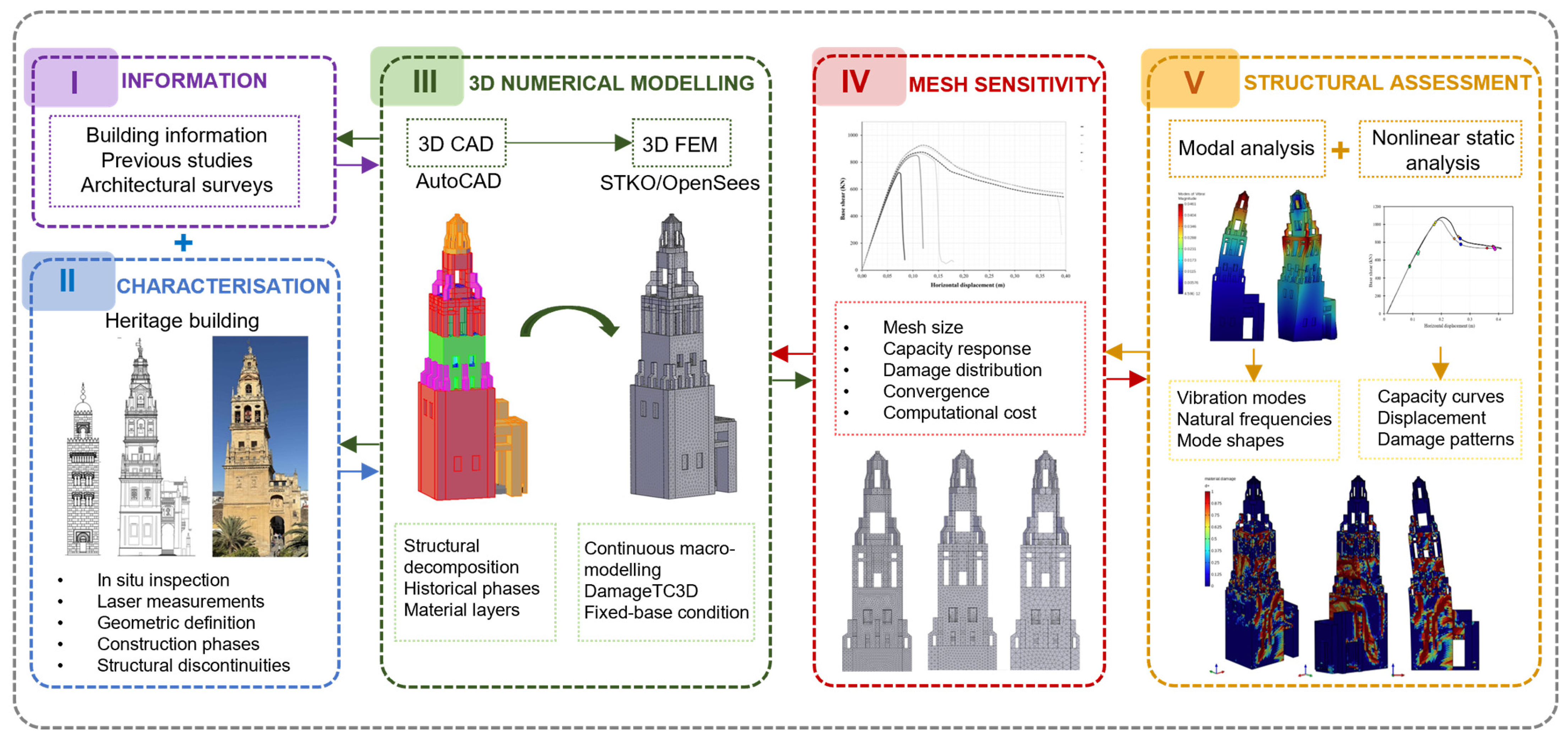
The methodology followed in this study builds upon previous numerical modelling approaches developed by the authors for the structural assessment of historical masonry structures [7,27,32] and is adapted here to the specific historical, geometrical and structural characteristics of the Bell Tower. The workflow followed in this study is summarised in Figure 1. It comprises five main stages.
Figure 1.
Workflow of the methodology followed in this study.
First, the available information on the Bell Tower of the Mosque-Cathedral of Córdoba was collected and critically reviewed. Historical documents, previous studies and architectural surveys were used to identify the main construction phases, interventions and structural characteristics of the tower. Particular attention was given to transformations that could influence its present structural configuration.
Second, the geometry and structural configuration of the tower were defined. The available graphical information was complemented with in situ observations. The main structural elements, openings, changes in wall thickness and relevant geometric and constructive discontinuities were identified. Given the limited accessibility of several parts of the monument, the uncertainties associated with the internal configuration were also identified and documented at this stage.
Third, this information was used to construct a simplified 3D CAD model and subsequently generate the 3D FEM in STKO/OpenSees. The geometry was simplified according to its structural relevance. Masonry was represented through a continuous macro-modelling approach using four-node tetrahedral solid elements and a nonlinear tension-compression damage model. A fixed-base (FB) condition was assumed.
Fourth, a mesh sensitivity analysis was performed. Different mesh sizes were compared in terms of numerical response, peak capacity, post-peak response, damage distribution, convergence behaviour and computational cost. The final mesh was selected based on these results.
Finally, modal and nonlinear static analyses were performed. Modal analysis was used to identify the main numerical dynamic properties of the case study and to compare the numerical modal response with empirical formulations and experimental results reported for comparable historical masonry towers. These comparisons provide a quantitative reference for the numerical modal response but do not constitute direct experimental validation of the FEM. The baseline model has not been experimentally calibrated at this stage. Nonlinear static analyses were subsequently carried out in the two principal horizontal directions using different lateral load patterns. Capacity curves, displacements and damage patterns were then analysed to assess the global structural response predicted by the FEM.
3. Case Study: Bell Tower of the Mosque-Cathedral of Córdoba
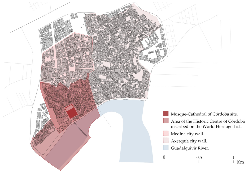
The Bell Tower of the Mosque-Cathedral of Córdoba is the highest structure of the monument and a key landmark within the historical urban landscape of Córdoba. The Mosque-Cathedral was inscribed in the UNESCO World Heritage List in 1984, with the recognition later extended to the surrounding Historical Centre (Figure 2).
Figure 2.
Area of Córdoba (Spain) included in the World Heritage List.
The present tower, located on the northwestern side of the Patio de los Naranjos, reaches an approximate height of 54 m and encloses the remains of the former Caliphal minaret built under Abd al-Rahman III in the 10th century.
3.1. Historical Evolution of the Tower
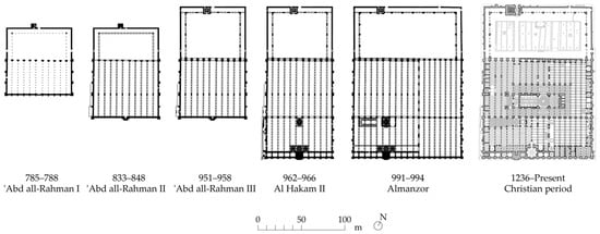
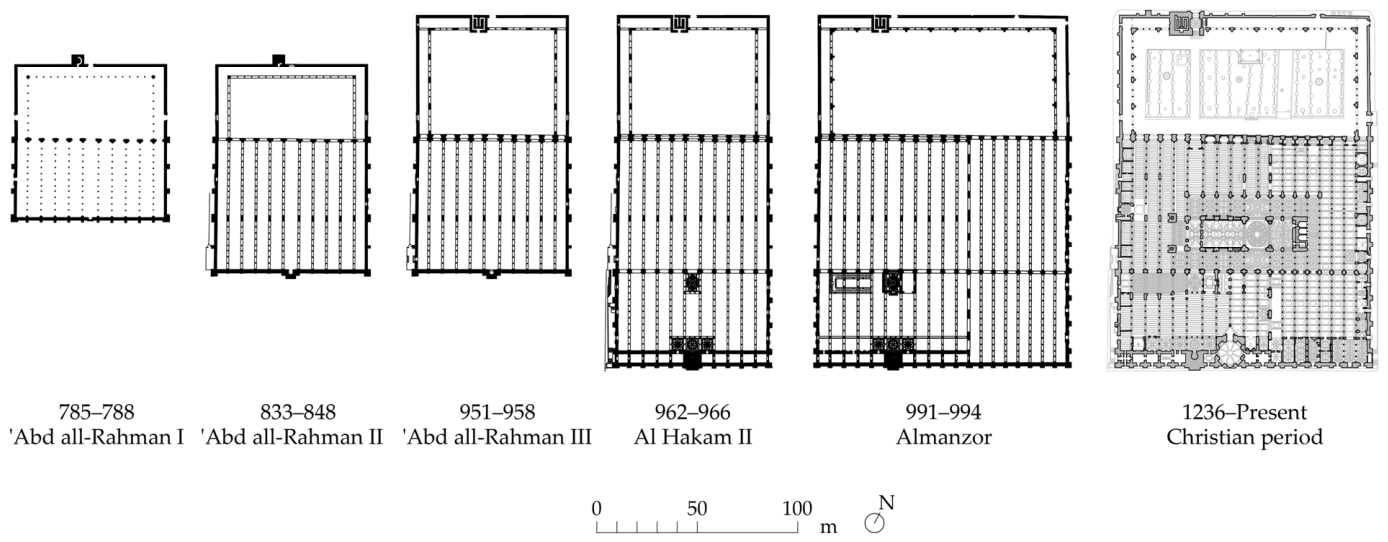
The current Bell Tower originates from the Caliphal minaret erected between 951 and 958 AD under Abd al-Rahman III, as part of the expansion of the Great Mosque. The original configuration of the minaret has been extensively studied through archaeological, architectural and documentary investigations. The main reference for understanding its geometry is [29], while [21] and [30] have refined its interpretation through updated graphic and virtual reconstructions (Figure 3).
Figure 3.
Chronological evolution of the ground plan of the Mosque-Cathedral of Córdoba (based on [21]).
Following the Christian conquest of Córdoba in 1236, the Mosque was consecrated as a cathedral, and the minaret was progressively adapted for use as a bell tower, remaining largely preserved for several centuries. A major transformation took place at the end of the 16th century, following the severe damage caused by the meteorological events of 1589 [33]. The adopted solution consisted of enclosing the existing minaret within a new masonry tower. This intervention, attributed to Hernán Ruiz III and completed in 1599, established the tower’s present configuration. This intervention increased the dimensions and the height of the tower, incorporating new architectural and structural elements. In that sense, the tower is a composite vertical structure formed by the interaction of an inner Islamic core and an outer Christian envelope [31].
The Lisbon earthquake of 1755 (Mw = 8.5) represents another relevant event in the historical evolution of the tower. Although it did not lead to a complete reconstruction of the Bell Tower, it forms part of the seismic history of the monument and provides an important historical reference for understanding the vulnerability of masonry heritage structures in southern Iberia. Later interventions, from the seventeenth century to the present, have mainly consisted of repairs and maintenance adaptations associated with public access [23].
Consequently, the present Bell Tower is the result of successive historical phases, which remain physically embedded within the current structure. This condition has direct implications for its structural interpretation and numerical modelling.
3.2. Structural Configuration
The present Bell Tower can be interpreted as a layered masonry structure, characterised by the coexistence and interaction of elements belonging to different construction periods. Its global behaviour is governed by the relationship established between the preserved Caliphal minaret and the Christian masonry envelope that surrounds it.
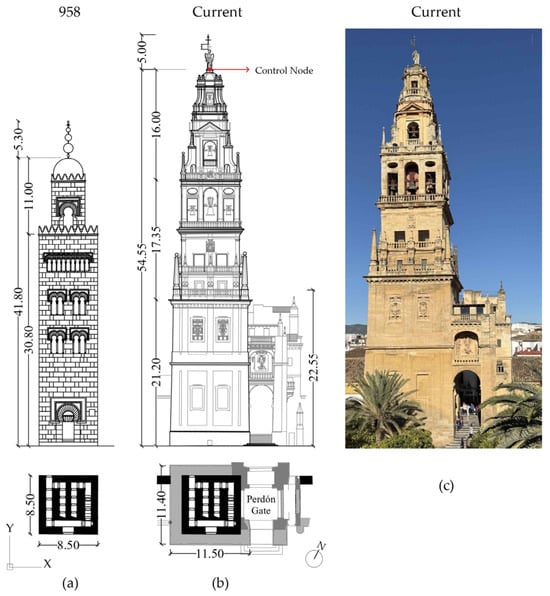
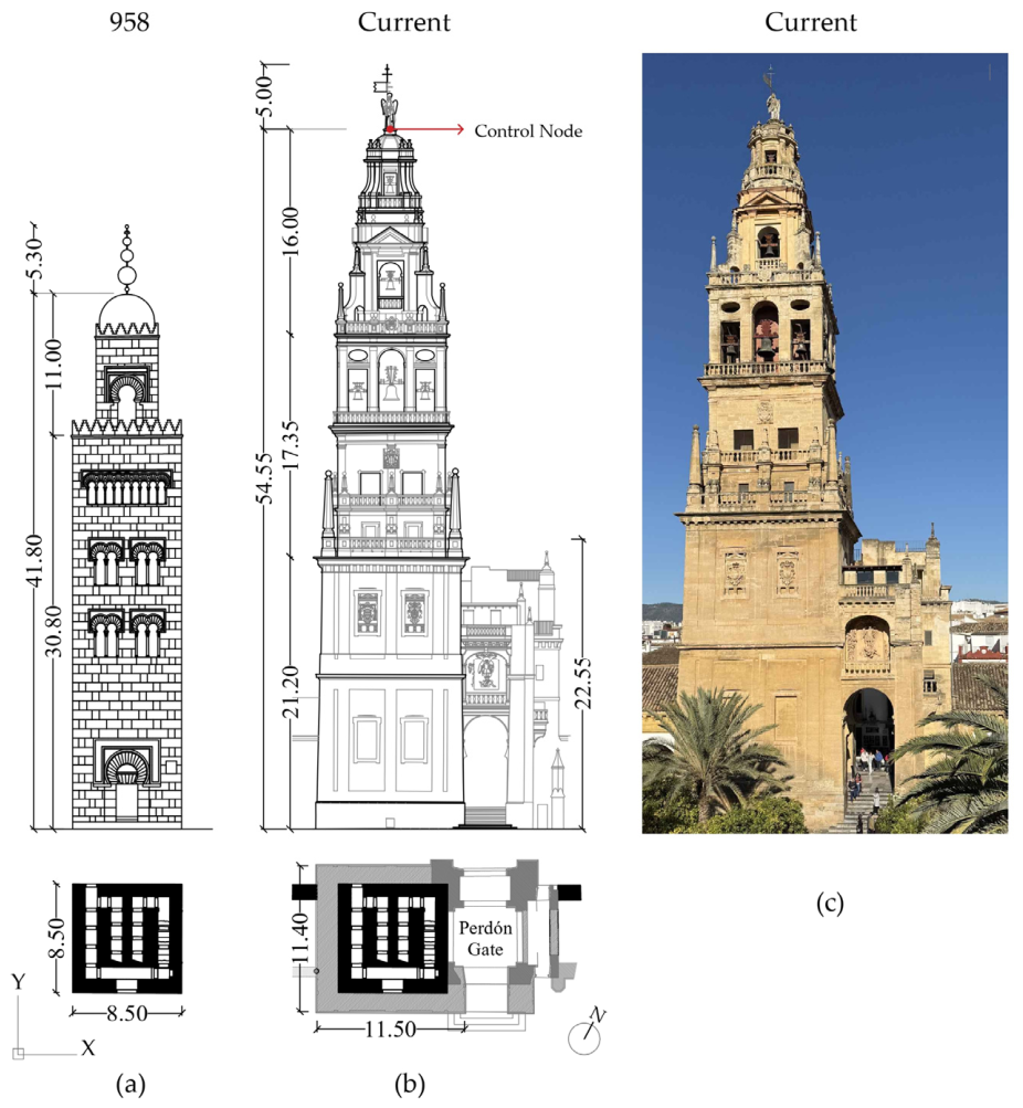
The inner structural core is formed by the remains of the 10th-century minaret. It has been analysed and reconstructed by Hernández Giménez (1975) [29], later refined by Ortiz Cordero (2018) [30] and Almagro Gorbea (2019) [21]. According to these works, the original structure consisted of a square-plan masonry tower. Two different ascent stairs ascend as far as the top level around the central masonry walls. This arrangement generated a compact and robust structural core, capable of efficiently transferring vertical loads (Figure 4).
Figure 4.
Evolution of the Bell Tower of the Mosque-Cathedral of Córdoba through south elevations and floor plans: (a) original Caliphal minaret; (b) Christian Bell Tower, including the Puerta del Perdón, with the location of the control node; and (c) current view of the tower. Based on [21].
Surrounding this nucleus, the Christian intervention introduced a second structural system, articulated in three superimposed bodies that enclosed the original minaret. Beyond its architectural role, this outer envelope participates actively in the global structural response of the tower by contributing additional stiffness, mass and load-transfer paths. The tower must be analysed as a combination of both structural systems: the Islamic minaret and the Christian bell tower.
The vertical distribution of mass and stiffness is not uniform along the height of the structure. The lower levels are characterised by the coexistence of the preserved minaret and the external masonry shell, generating a comparatively massive and stiff structural section. In contrast, the upper bodies contain larger openings, bell chambers and more articulated architectural configurations, resulting in a progressive reduction in stiffness with the height.
Openings, internal circulation elements and the interfaces between successive construction phases further contribute to the complexity of the structural system. In addition, the tower is not fully isolated from the surrounding architectural context. At its base, the presence of the Puerta del Perdón and the adjacent perimeter galleries extending predominantly along the east–west direction introduces partial restraint conditions that may influence the global structural response. In this regard, the Puerta del Perdón has the greatest influence on the boundary conditions.
This structural interpretation is essential for the development of the numerical model. The Bell Tower is understood as a composite masonry system, shaped by the interaction between the preserved minaret, the Christian envelope, internal discontinuities and adjacent restraints. This condition defines the basis for identifying the main modelling uncertainties addressed in the following section.
4. Identification and Treatment of Modelling Uncertainties
The development of a representative Finite Element Model of a historical masonry tower inevitably involves a degree of uncertainty. Unlike modern constructions, where geometry, structure, materials and construction details are well-documented, heritage buildings often present uncertainties derived from successive construction phases, transformations, repairs and adaptations accumulated over centuries. Consequently, several aspects governing their structural behaviour cannot be directly observed or characterised with complete certainty.
In the case of the Bell Tower of the Mosque-Cathedral of Córdoba, these challenges are further amplified by the coexistence of the preserved Caliphal minaret and the later Christian masonry envelope. It is a complex multi-phase structure whose current configuration reflects more than a millennium of architectural evolution. The main sources of uncertainty concern the interpretation of historical evidence, the definition of the internal geometry, the characterisation of materials and construction techniques, the assessment of the interactions between structural components belonging to different construction periods and the definition of boundary conditions associated with adjacent architectural elements.
To ensure the transparency and reproducibility of the modelling process, the main sources of uncertainty considered in this study are identified and discussed in the following sections. These uncertainties are subsequently addressed through explicit modelling assumptions, which constitute the basis of the FEM developed in this work.
4.1. Historical Uncertainty
Historical uncertainty is mainly associated with the long constructive evolution of the Bell Tower and with the partial transformation of the original Caliphal minaret during later interventions. Table 1 summarises the main historical milestones relevant to the structural interpretation of the tower.
Table 1.
Main historical milestones relevant to the structural interpretation of the Bell Tower of the Mosque-Cathedral of Córdoba.
The first phase corresponds to the construction of the Caliphal minaret between 951 and 958. This phase provides the main underlying structural core of the tower and defines the initial geometry from which later transformations developed. A major source of uncertainty is related to the Christian transformation of the minaret into a bell tower between 1593 and 1599 by Hernán Ruiz III, following the documented damage event of 1589 [29,33]. This intervention altered the architectural and structural configuration of the original Islamic tower. A particularly relevant issue is the demolition of the second body and part of the upper portion of the first body of the minaret [29]. This introduces uncertainty regarding the extent to which the original Islamic structure is preserved within the current tower.
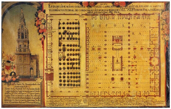
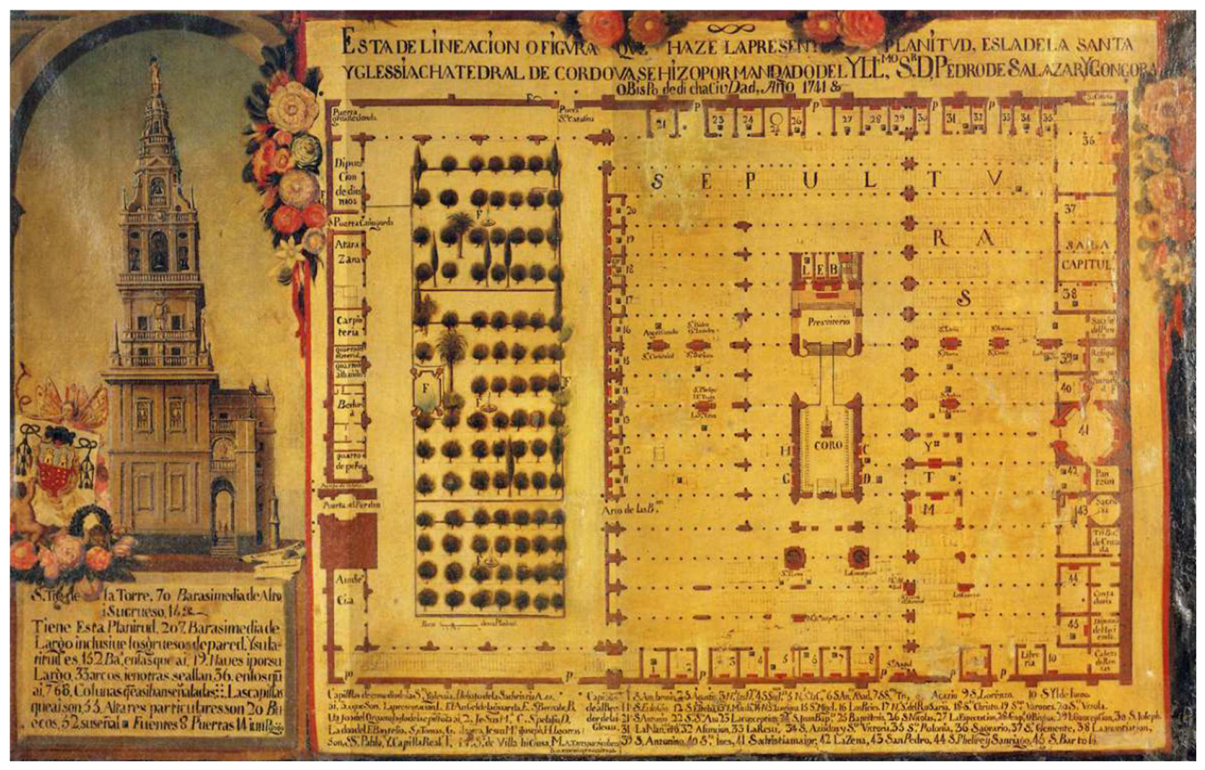
Later events, such as the effects of the 1755 Lisbon earthquake (Mw = 8.5) on the Bell Tower, are not fully documented from a structural point of view. In this context, the buttressing elements located in the connection between the current lower body and the second body were constructed as part of reinforcement measures, after seismic damage (Figure 5). Consequently, these historical interventions increase the complexity of defining construction phases, and the distinction between preserved, modified and reconstructed components.
Figure 5.
Mosque-Cathedral of Córdoba floor plan and Bell Tower in 1741 (before the 1755 Lisbon Earthquake). Oil painting preserved in the Archive of the Cathedral of Córdoba, representing the floor plan of the building [23].
These historical uncertainties directly affect the definition of the numerical model, particularly the identification and representation of components belonging to different construction phases. In the present study, the main structural phases identified from the available historical evidence are explicitly distinguished in the geometrical model, namely the preserved Caliphal minaret and its subsequent Christian transformations. The implementation of these construction phases in the 3D CAD model is described in Section 5.1. Uncertainties that cannot be resolved from the available historical and physical evidence are retained as limitations of the baseline model and are considered in the interpretation of the numerical results.
4.2. Geometrical Uncertainty
Geometrical uncertainty is primarily associated with the structural idealisation adopted for the tower and with the difficulty of defining some inaccessible internal configurations. The baseline model is not intended to reproduce every architectural detail of the monument, but to represent the main structural elements involved in the global behaviour of the tower. Accordingly, the geometry is analysed and simplified into the main vertical and horizontal load-bearing components. The decorative features, ornaments and secondary architectural details are not explicitly modelled.
The global geometry model is supported by historical references, architectural drawings, previous reconstruction studies and in situ visual inspection and measurements.
The Islamic minaret can be described as a compact square-plan masonry structure, with an external side length of approximately 8.485 m at ground level [29]. Its interior is organised as a masonry core defined by the perimeter walls, two central masonry piers and a central longitudinal wall, forming two stair compartments. Each accommodates a stone stair that rises in the opposite direction to the other and meets it only in the upper part of the minaret (Section Internal Stairs and Wall thickness Variation).
The height of the Caliphal minaret is less directly verifiable in the present tower, since its upper bodies were later transformed and partially demolished during the Christian works. Nonetheless, previous reconstruction studies provide a well-founded dimensional hypothesis [29,30], estimating a total height of around 47 m: a lower body of approximately 30.8 m, an upper body of about 10.9–11.0 m, and a crowning system formed by a hemispherical bronze dome, approximately 4.2–4.3 m in diameter, and the yamur, approximately 5.3 m high (Figure 4).
The geometry of disappeared elements is difficult to define, particularly above the approximate elevation of 22.55 m. Available studies indicate that the second body and part of the upper portion of the first body of the minaret were demolished [29]. Therefore, the effective preservation of the original minaret above this level cannot be established with the same degree of certainty as in the lower preserved portions.
The Christian bell-tower transformation enlarged the footprint of the original minaret and changed the cross-sectional configuration of the tower. Therefore, the present structure cannot be understood as an isolated Caliphal core or as an independent Christian envelope, but as a composite masonry system. The main geometrical uncertainty concerns the contact zones between both phases, especially where interfaces, blocked openings, altered accesses or possible infill zones are not directly accessible.
These geometrical uncertainties have been considered in the development of the numerical model through the geometrical idealisation and simplification of the main structural components. The corresponding modelling assumptions and their implementation in the 3D model are described in Section 5.1.
Internal Stairs and Wall Thickness Variation
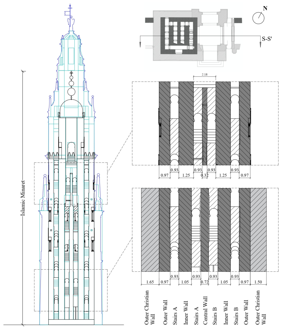
The internal stair and wall arrangement of the original minaret represents one of the main sources of geometrical uncertainty, as it controls the distribution of internal voids, wall continuity and stiffness in the masonry core. According to the available documentation, the Caliphal minaret originally included two independent stair compartments, arranged symmetrically in plan and separated by a central longitudinal wall. These stair systems developed independently through most of the height and converged in the upper part into a single wider stair zone.
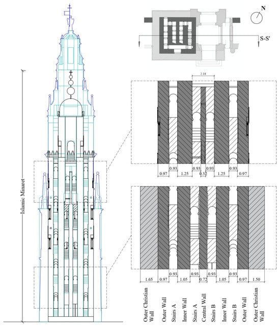
The stair compartments maintained an approximately constant width of 0.93 m, while the surrounding masonry walls varied in thickness along the height. In the lower portion, the external walls are reported to have a thickness of approximately 1.05 m, while the central wall separating the two stair compartments is approximately 0.72 m thick. At around 3/4 of the height of the internal wall development, this wall thickness arrangement changes: the external walls increase to approximately 1.25 m, whereas the central dividing wall is reduced to approximately 0.32 m. The stair compartments therefore preserve their width while adapting to the changing thickness of the adjacent masonry walls (Figure 6).
Figure 6.
Schematic configuration of the Bell Tower of the Mosque-Cathedral of Córdoba: section of the different structural elements. The black line represents the section of the original minaret [24], the dark blue line corresponds to Almagro’s elevation drawing [21], and the green line shows the section extracted from the proposed 3D FEM.
In the final upper portion, the central longitudinal wall disappears and the two stair compartments merge into a single central stair zone, with an approximate width of 2.18 m. This transition is geometrically and structurally significant because it modifies the distribution of internal voids and the continuity of the masonry core. However, its exact local geometry and its connection with later transformations cannot be established with the same degree of certainty as the main wall volumes.
For this reason, the baseline geometrical model reproduces the internal stair system, considering its main geometrical and structural implications: the presence of internal stair voids, the variation in wall thickness, the reduction and disappearance of the central longitudinal wall in the upper portion. This approach allows the model to represent the principal structural effects of the internal organisation. However, minor local irregularities and decorative features associated with the stair coverings are not modelled, as they are not considered governing elements for the global structural response.
4.3. Constructive Uncertainty
Constructive uncertainty concerns the materials, construction techniques, state of conservation and mechanical interaction between the different historical components of the tower. Unlike geometrical uncertainty, which mainly affects the definition of modelled volumes, internal voids and interfaces, constructive uncertainty concerns how these components are built, connected and able to transfer loads under static and seismic actions.
At the present stage of the research, a mechanical characterisation of the masonry of the Bell Tower is not available. Therefore, the mechanical properties adopted in the numerical model must be derived from different sources: previous research works carried out on the Mosque [26], the parameters proposed by seismic codes, and other research works published in the literature.
This uncertainty is particularly relevant because the tower is not a homogeneous construction. The preserved Caliphal core, the later Christian masonry envelope, subsequent repairs and local modifications may differ in construction technique, masonry texture, unit arrangement, mortar condition, wall-leaf connection and state of conservation. These features are directly related to masonry quality, which has been shown to influence the expected structural response of historical masonry, including the development of monolithic behaviour, local mechanisms and possible disaggregation [34,35].
Constructive uncertainty therefore concerns not only the selection of material parameters but also the way in which the masonry fabric transfers loads between connected components. This is especially relevant at the interface between the Caliphal core and the Christian envelope, where contact surfaces, infill masonry, landings, slabs, stair structures or later local connectors may link both phases at specific levels. As a result, the degree of collaboration between the inner core and the outer shell remains uncertain.
The internal morphology of the masonry sections also remains partly uncertain, especially in areas that cannot be directly inspected. This aspect is relevant because the through-thickness arrangement of masonry units, the presence or absence of transverse connections, and the degree of interlocking between wall leaves can significantly affect the monolithic behaviour and out-of-plane response of historical masonry [35]. Consequently, the possible existence of heterogeneous infill zones, discontinuous connections or locally modified masonry must be considered as part of the constructive uncertainty of the tower.
A specific constructive feature of the Caliphal minaret is the presence of timber tie beams embedded within the masonry. Previous studies identify two timber beams located above the two orders of windows of the middle body, formed by pine beams housed in channels within the masonry [29,30]. Since only fragments are preserved and the remaining recesses are visible as approximately square cavities, their current mechanical role cannot be established with certainty. They may have originally contributed to horizontal tying and wall continuity, but their present degraded condition may also introduce local discontinuities and reductions in the effective masonry section [31]. For this reason, their influence is considered as a construction-related uncertainty.
Additional uncertainty is associated with hidden infills, blocked openings, modified internal sectors and local reinforcement elements introduced during later transformations or adaptation works. These elements may affect local stiffness, load transfer and stress redistribution between adjacent masonry components.
The way in which these construction-related uncertainties are translated into modelling decisions is described in Section 5.3.
4.4. Boundary Condition Uncertainty
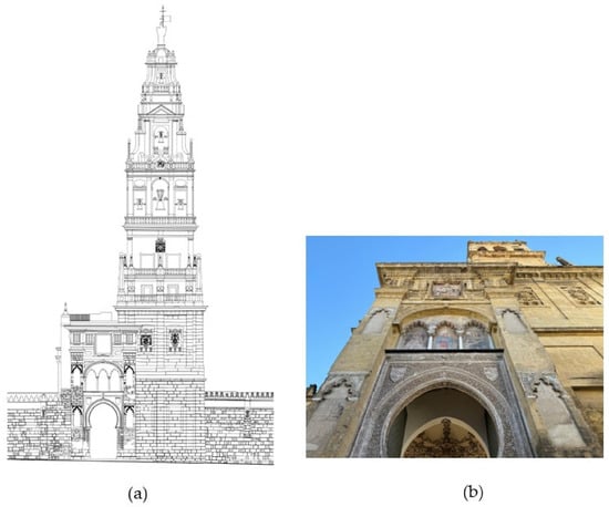
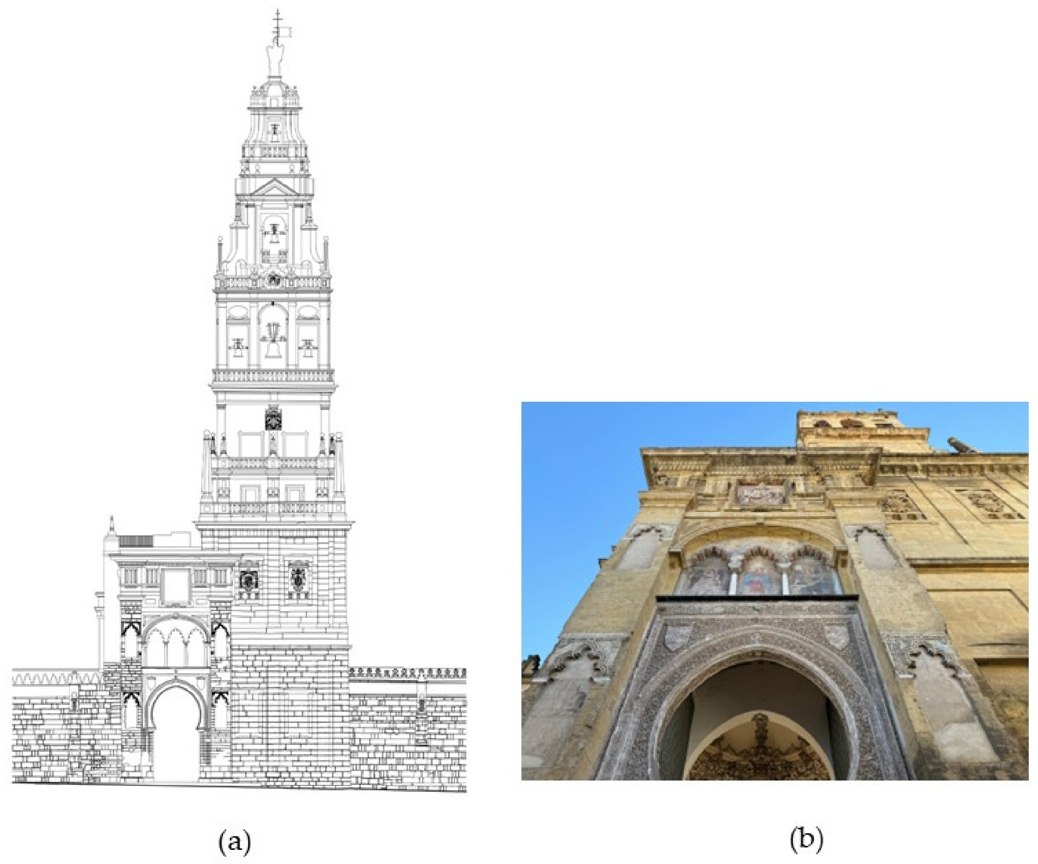
Boundary condition uncertainty is associated with the interaction between the Bell Tower and the surrounding architectural elements of the Mosque-Cathedral complex. Although the tower has a clear vertical structural identity, it cannot be considered a completely isolated body. At its lower levels, it is connected to the Puerta del Perdón (Figure 7) and is located within the architectural system of the Patio de los Naranjos.
Figure 7.
Puerta del Perdón: (a) North elevation drawing [21] and (b) current view of the north façade.
These adjacent structures may influence the structural response of the tower by modifying the effective lateral restraint, local stiffness distribution and deformation pattern. The complete inclusion of the surrounding Mosque-Cathedral complex is beyond the scope of the present baseline model. Accordingly, the influence of the rest of the monumental complex is recognised as a boundary condition uncertainty and must be considered when interpreting the numerical results.
5. Baseline 3D Numerical Model of the Bell Tower
Based on the historical, geometrical, constructive and boundary-condition uncertainties identified in Section 4, the geometrical model was developed by retaining the main structural features governing the global response of the tower while applying the simplifications required for the subsequent FEM generation. The main uncertainties, the corresponding baseline FEM assumptions, the scenarios examined, and their potential influence on the results are summarised in Table 2.
Table 2.
Summary of the main modelling uncertainties, baseline FEM assumptions, scenarios examined and potential influence on the results.
5.1. Geometrical Model: CAD
The 3D geometric model was based on a detailed study of the tower, integrating historical documentation, previous architectural research and in situ survey data. The main geometrical basis was provided by the architectural drawings by Almagro [21], the thesis by Ortiz [30] and the work of Hernández Giménez [29], the latter especially for the configuration of the original Caliphal minaret. This information was subsequently cross-checked and refined through in situ inspections, in situ measurements and image-based analysis. The geometric model was developed in AutoCAD 2026.
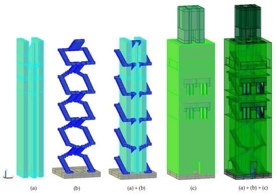
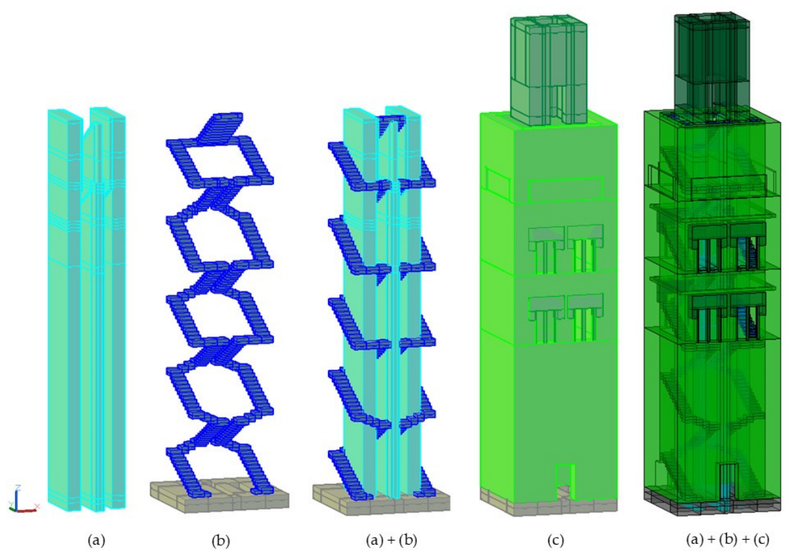
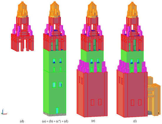
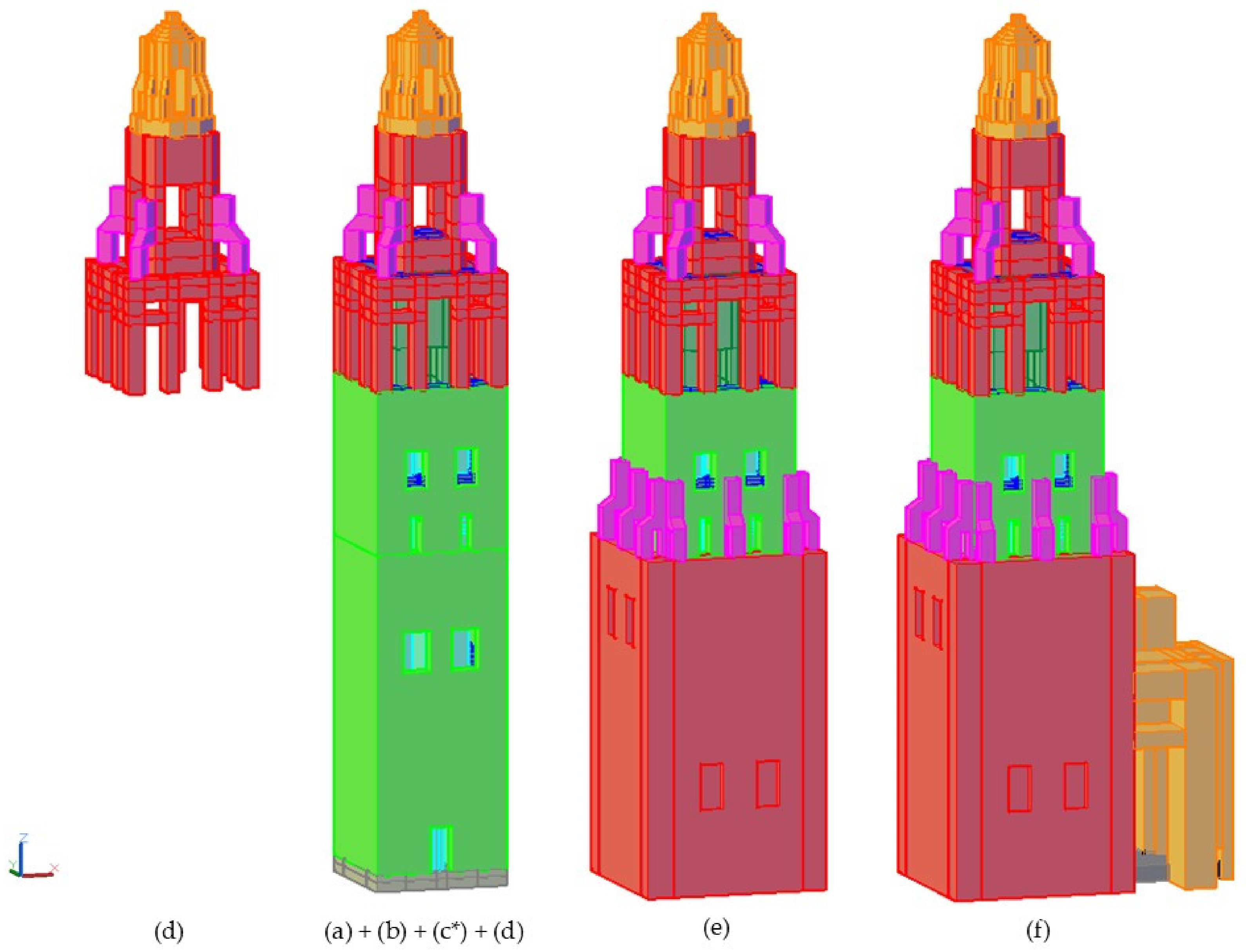
As shown in Figure 8, the model includes the main components required to represent the structural configuration of the tower. The internal configuration of the Caliphal minaret includes the internal masonry piers, wall thickness variations, the central wall system, the floor levels and the two symmetrical staircases that merge near the upper part of the structure. Once the internal system had been defined, the external shaft of the minaret was incorporated. The openings were represented through simplified geometric voids, while the cavities associated with timber tie beams were included as local discontinuities. Following this, the Christian transformations were modelled on the Islamic minaret model (Figure 9) in order to reproduce the constructive evolution of the tower. This CAD model includes the belfry level, the upper crowning elements, the Christian basement wall and the buttresses. Finally, the Puerta del Perdón was incorporated into the model as the main boundary condition. The simplification process focused on the structural elements. Secondary architectural details have been omitted to keep the FEM robust and computationally feasible [7].
Figure 8.
Three-dimensional CAD model of the original Caliphal minaret: (a) internal central walls; (b) paired staircase system; (a)+(b) internal structural configuration; (c) external minaret shaft with original openings; and (a)+(b)+(c) complete geometric model.
Figure 9.
Three-dimensional CAD model of the Christian transformations of the Bell Tower: (d) upper bell chamber and crowning elements; (a)+(b)+(c*)+(d) integration of the Caliphal minaret with the upper Christian additions and modified external shaft (openings); (e) Christian basement wall and lower buttresses; and (f) final geometric model including the Puerta del Perdón. (c*) indicates a modified version of component (c) shown in Figure 8, in which the openings were adapted to the Christian transformation.
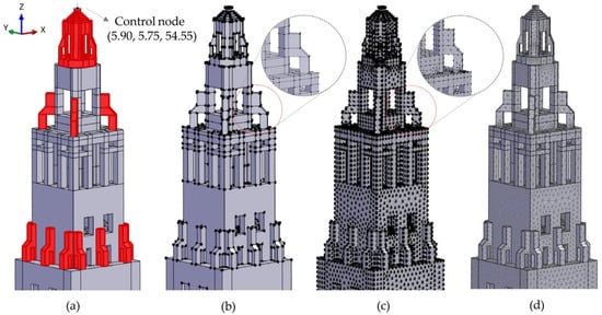
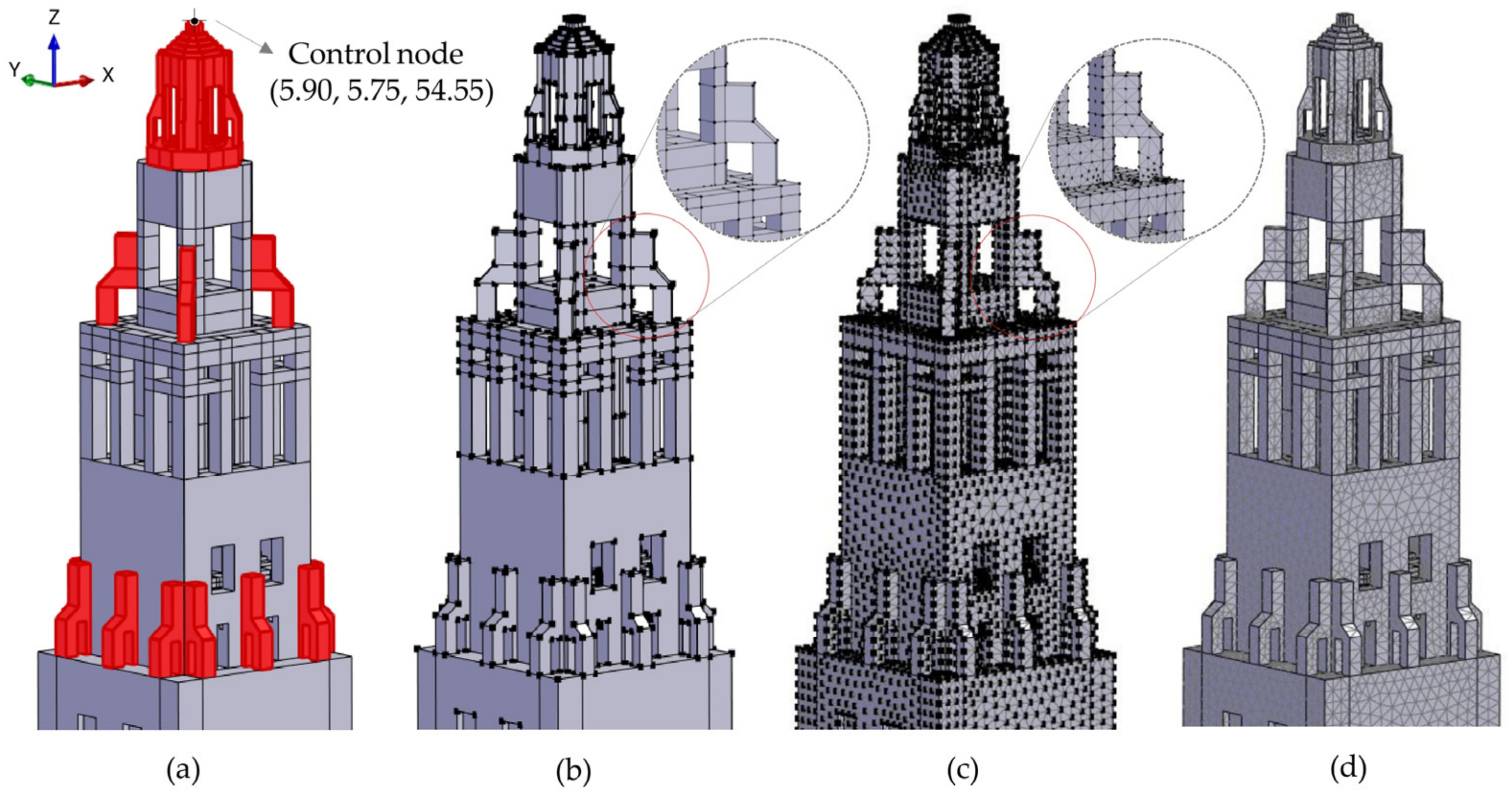
To facilitate the subsequent FEM discretisation and ensure geometrical compatibility between adjacent components, the complex geometry was represented, whenever possible, through simplified prismatic volumes. Where structural components intersect, they were subdivided into smaller volumes with coincident boundaries to avoid unintended gaps or overlaps that could generate disconnected nodes and compromise mesh continuity. Minor dimensional discrepancies between adjacent components, when considered negligible for the global structural response, were regularised to ensure compatible connections. The geometrical model was developed through an iterative CAD–STKO procedure, in which structural components were progressively incorporated, and their geometrical compatibility and mesh connectivity were checked. Complex components required specific idealisations; for example, the upper buttresses were subdivided into three connected volumes, whereas the lower buttresses were represented as single volumes (Figure 10). These simplifications were adopted to obtain a geometrically consistent and meshable model while retaining the main structural configuration governing the global response of the tower.
Figure 10.
Geometrical idealisation and FEM procedure: (a) identification of geometrically complex structural elements (highlighted in red) and location of the control node; (b) subdivision of intersecting components into compatible prismatic volumes and definition of guide nodes for complete mesh generation; (c) FE discretisation and detail of mesh connectivity; and (d) final 3D FEM.
The organisation into separate entities and CAD layers also preserved the distinction between the main historical construction phases, allowing them to be independently identified in the subsequent implementation in STKO and the definition of the FEM. In addition, the upper bodies were divided into four symmetric parts in plan to easily access the central nodes (Figure 9).
5.2. Finite Element Model (FEM) Discretisation: STKO/OpenSees
The Finite Element Model (FEM) was developed using the STKO/OpenSees workflow [36]. The geometrical CAD model was imported into STKO Release 4.1.0, which was used as pre- and post-processor. The X and Y axes of the numerical model correspond to the west–east and to the south–north cardinal directions, respectively (Figure 9).
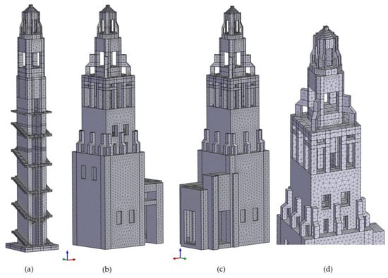
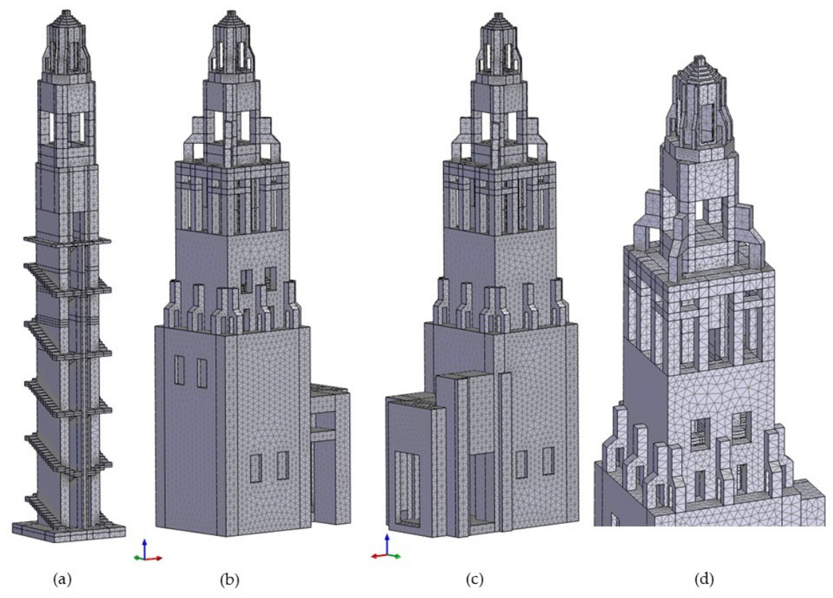
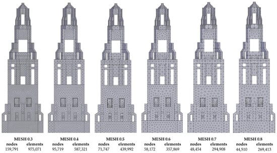
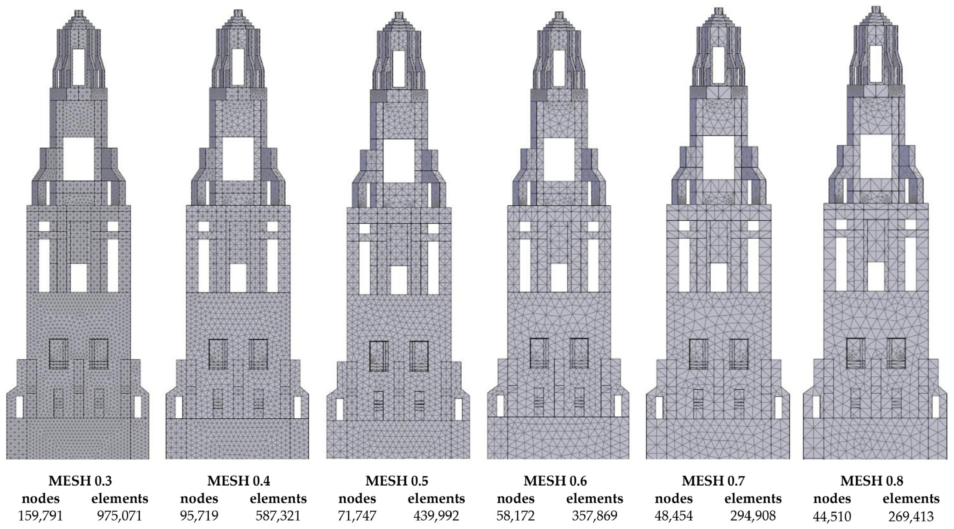
A continuous macro-modelling approach [15] has been adopted due to the scale and geometric complexity (Figure 11). Masonry has been represented as an equivalent continuum and discretised using an unstructured tetrahedral mesh of four-node tetrahedral solid elements [7]. A mesh sensitivity analysis was carried out to define a suitable discretisation for the baseline FEM. Different mesh sizes have been analysed (Figure 12), to assess their influence on the numerical response, damage distribution, convergence behaviour and computational cost. The final mesh 0.6 m has been selected as a compromise between numerical stability, damage distribution and computational efficiency. The detailed mesh sensitivity results are presented in Section 6.2.
Figure 11.
Three-dimensional FEM model: (a) inner body and stairs; (b) west and south façades; (c) east and north façades; (d) belfry and upper level.
Figure 12.
Mesh discretisations considered in the sensitivity analysis of the 3D FEM, with the corresponding number of nodes and elements.
5.3. Masonry: Material Model and Mechanical Parameters
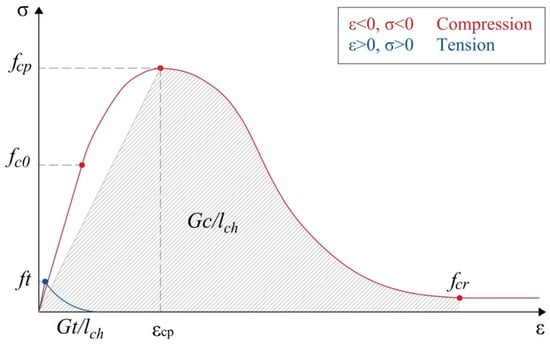
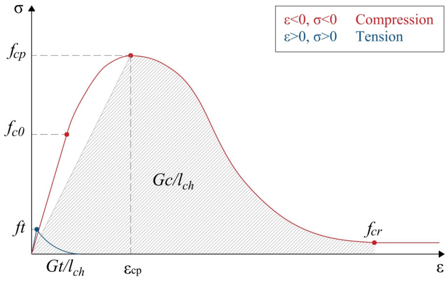
Following previous numerical studies on complex masonry heritage towers conducted by the authors [7], the nonlinear behaviour of the stone masonry has been simulated using the 3D Tension-Compression Damage model (DamageTC3D) [37,38] implemented in STKO/OpenSees. Within the adopted macro-modelling approach, masonry is represented as an equivalent continuum. DamageTC3D is based on a tension–compression continuum damage formulation that distinguishes between the nonlinear response of the material under tensile and compressive stress states through separate damage variables [37]. The constitutive response is defined by distinct uniaxial laws in tension and compression, as illustrated in Figure 13. The tensile response is characterised by post-peak softening, whereas the compressive response accounts for the nonlinear evolution of the material up to the peak strength and its subsequent post-peak degradation. The post-peak response is formulated in terms of fracture energy and characteristic element length to regularise the softening behaviour with respect to the finite-element discretisation [37].
Figure 13.
Uniaxial stress–strain relationships of the DamageTC3D material model under tension and compression.
The mechanical parameters of the stone masonry adopted in the baseline FEM are summarised in Table 3, based on previous research studies and a calibrated numerical model carried out by the authors [7,27]. Furthermore, the mechanical parameters proposed by the Italian code [39] and the Spanish code [40] and other published studies [41] have been considered in their definition.
Table 3.
Mechanical and constitutive parameters of the stone masonry used in the 3D FEM.
The interfaces between adjacent masonry components were assumed to be perfectly bonded in the baseline FEM. This modelling assumption was adopted, considering the presence of mortar layers connecting the different masonry leaves. These leaves were therefore assumed to act monolithically in the baseline FEM. Accordingly, no relative sliding or separation was considered at these interfaces.
5.4. Nonlinear Analysis Settings
A static analysis under vertical loads was performed first. Two lateral load patterns were considered: a mass-proportional pattern (M) and a mass-and-height-proportional pattern (MH), following the approach commonly adopted in pushover analyses of masonry structures and consistent with Eurocode 8 provisions [42,43]. Each pattern was applied in the positive and negative X and Y directions.
The pushover analyses were performed under displacement control. The control node was located at the highest modelled level, 54.55 m above the model base, at the centre of the tower in plan, as indicated in Figure 4b and Figure 10a. Its horizontal displacement was controlled in the direction of the applied lateral load, using degree of freedom (DOF) 1 for analyses in the X direction and DOF 2 for analyses in the Y direction. Capacity curves were expressed as base shear versus displacement at this node. The numerical solution settings are summarised in Table 4.
Table 4.
Numerical solution settings for the nonlinear static analyses.
The displacement increment was adaptively adjusted during the analysis. The stopping conditions were reaching the prescribed target control-node displacement of 0.40 m or failure to achieve convergence.
For the presentation of the pushover results (Section 6.3), the ultimate displacement was defined at a 20% reduction from the peak base shear on the descending branch. The capacity curves were presented up to this displacement, and the numerical damage patterns corresponded to the same stage. This threshold was applied during post-processing.
6. Results and Discussion
6.1. Modal Analysis
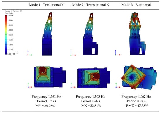
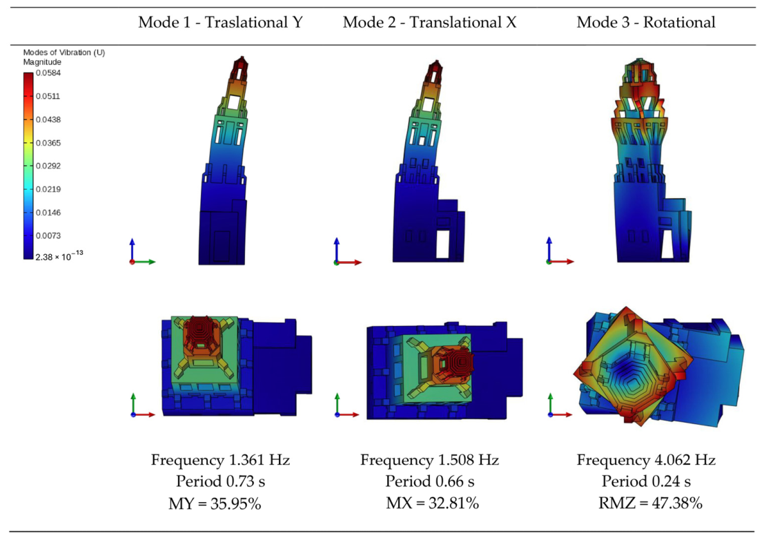
First, a modal analysis has been carried out to evaluate the global dynamic response of the baseline FEM. The natural frequencies and periods of the first three modes are summarised in Figure 14.
Figure 14.
Main vibration modes of the tower.
The first two modes correspond to the main translational responses of the tower. The first mode is mainly translational in the Y direction, with a frequency of 1.361 Hz, a period of 0.734 s and a modal participation mass ratio of 35.95% in the Y direction. The second mode is mainly translational in the X direction, with a frequency of 1.508 Hz, a period of 0.663 s and a modal participation mass ratio of 32.81% in the X direction. The proximity between these two frequencies indicates that the baseline model presents a comparable global stiffness in the two principal horizontal directions. Nevertheless, the slightly lower frequency obtained in the Y direction suggests a more flexible response along this axis due to the boundary conditions. The third mode, with a frequency of 4.062 Hz and a period of 0.246 s, is mainly rotational, with a torsional modal participation mass ratio of 47.38% about the vertical axis. This mode shape is consistent with the geometric irregularity of the tower, the influence of the adjacent Puerta del Perdón and the non-uniform distribution of stiffness along the height.
To provide a quantitative reference for the numerical modal response, the fundamental frequency (f1) was compared with empirical formulations previously proposed for masonry towers [44,45,46]. Shakya et al. [45] developed several empirical relationships from a database of slender masonry structures whose dynamic properties were experimentally identified through AVT. For masonry towers, the empirical formulation, accounting for both the total height (H) and the minimum plan dimension (L) (Equation (1)), provides the highest coefficient of determination, equal to 0.96 within the database considered by the authors.
The empirical law proposed by Shakya et al. is as follows [45]:
A second estimate was obtained using the expression included in the Spanish Seismic Building Code (NCSE-02) [46]:
The empirical formulations have been applied to selected historical masonry towers for which experimentally identified fundamental frequencies are available (Table 5). Towers structurally connected to adjacent buildings were preferentially considered because the Bell Tower of the Mosque-Cathedral of Córdoba is connected to the adjacent Puerta del Perdón. Previous experimental studies have shown that the interaction with adjacent structures can significantly affect the dynamic response of masonry towers [44].
Table 5.
Comparison between experimentally identified (AVT) and empirically estimated fundamental frequencies and periods for selected masonry towers structurally connected to adjacent buildings.
In addition to the fundamental frequencies, the relationship between the first three modal frequencies was examined. The numerical model provides ratios f2/f1 equal to 1.11 and f3/f1 equal to 2.98. Diaferio et al. [44] reported mean experimental ratios of 1.14 and 3.15, respectively, for masonry towers structurally connected to adjacent buildings. The numerical ratios are therefore close to the mean experimental values reported for this tower typology. These quantitative comparisons show that the numerical modal response is consistent with experimental trends reported for comparable historical masonry towers, but do not constitute direct experimental validation of the FEM.
6.2. Mesh Sensitivity Analysis
A mesh sensitivity analysis has been performed to assess the influence of the finite element discretisation on the nonlinear response of the tower. Six characteristic mesh sizes were analysed, ranging from 0.3 m to 0.8 m (Figure 12). The comparison considered the number of nodes and elements, the computational cost, the convergence behaviour, the capacity curves and the damage distribution.
As expected, the refinement of the mesh significantly increased the size of the numerical model (Figure 12). The 0.3 m mesh led to 159,791 nodes and 975,071 elements, whereas the 0.8 m mesh reduced the model to 44,510 nodes and 269,413 elements. This reduction had a direct effect on computational cost but also affected the representation of damage concentration. In this context, previous studies on masonry towers have suggested that the mesh size should be selected by considering the number of elements through the wall thickness, together with the stability of the nonlinear response and the computational cost [18].
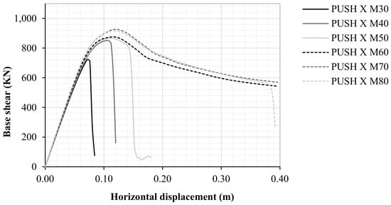
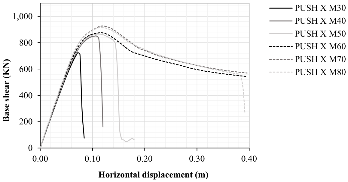
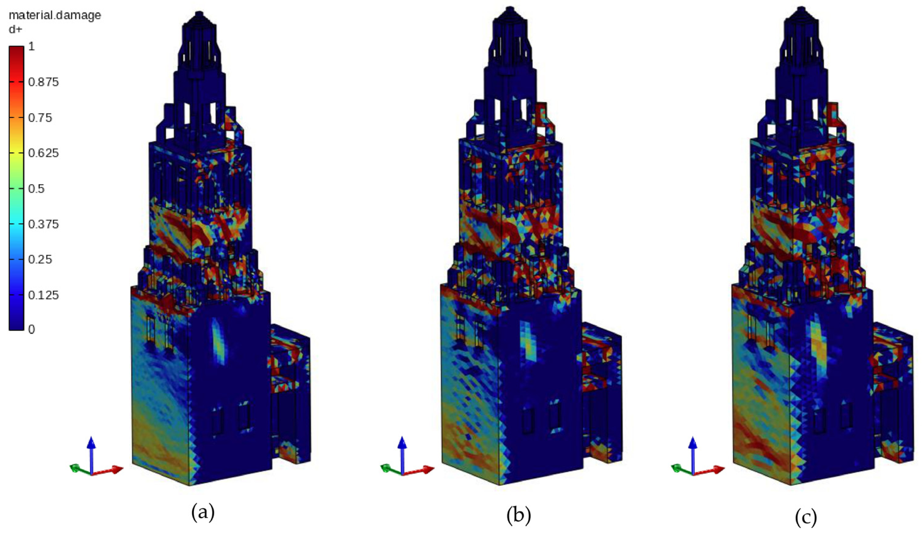
The pushover curves obtained with the different meshes are shown in Figure 15. The finer meshes provided a more detailed representation of the geometry and damage distribution (Figure 16), particularly around openings, wall thickness variations and the upper bell chamber. However, the 0.3 m, 0.4 m and 0.5 m meshes exhibited sharper post-peak drops and less stable nonlinear branches. This behaviour suggests that the finer meshes may lead to more localised damage and more demanding convergence conditions during the nonlinear analysis.
Figure 15.
Mesh sensitivity analysis in the X direction: comparison of pushover capacity curves obtained for characteristic mesh sizes between 0.3 m and 0.8 m. In the legend, “PUSH” denotes the pushover analysis, “X” indicates the analysis direction, and “M” denotes the mesh, followed by its characteristic size (M30-M80 corresponding to 0.30–0.80 m).
Figure 16.
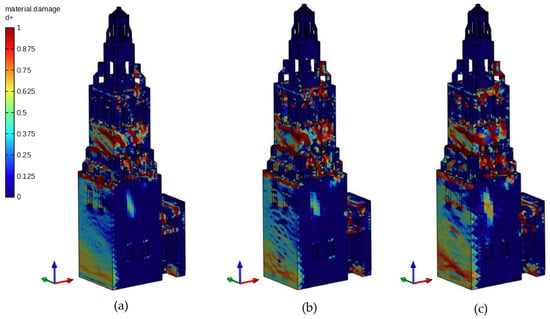
Numerical damage patterns obtained for different characteristic mesh sizes: (a) 0.5 m, (b) 0.6 m and (c) 0.7 m. The comparison shows the influence of mesh discretisation on the definition of local damage mechanisms.
The peak base shear, the corresponding displacement and computational time obtained for each mesh size are summarised in Table 6.
Table 6.
Quantitative comparison of the mesh sensitivity analyses.
By contrast, the larger mesh sizes showed a smoother post-peak response and lower computational cost. However, excessively large mesh sizes may reduce the definition of local damage mechanisms and simplify relevant geometric features (Figure 16). In this regard, the 0.7 m and 0.8 m meshes provided stable global curves, but their lower geometric resolution may make them less suitable for a detailed FEM of such a complex tower.
All the models were divided into 24 partitions and analysed on the same workstation, equipped with an AMD Ryzen Threadripper PRO 5995WX 64-core processor. The computation times for the different mesh sizes are reported in Table 6. The 0.3 m mesh required 0:15:23, approximately 3.4 times the computation time of the 0.6 m mesh (0:04:30). Although these computation times correspond to the nonlinear static analyses performed in this study, computational cost becomes particularly relevant when considering future nonlinear dynamic analyses.
Based on this comparison, the 0.6 m mesh was selected as the baseline discretisation for the subsequent nonlinear static analyses. This mesh consists of 58,172 nodes and 357,869 elements. It provides a reasonable compromise between geometric representation, numerical stability, convergence behaviour and computational efficiency. The 0.4, 0.5 and 0.6 m meshes yielded similar peak base-shear values, ranging from 850.392 to 875.267 kN. Compared with the 0.6 m mesh, the 0.3 m mesh yielded a peak value 17.3% lower, whereas the 0.7 and 0.8 m meshes yielded values 5.9% and 4.7% higher, respectively. This choice should not be interpreted as an absolute optimum, but as a consistent modelling decision for the baseline FEM.
6.3. Nonlinear Static Analysis
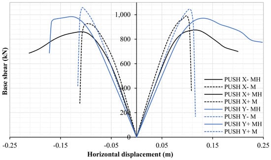
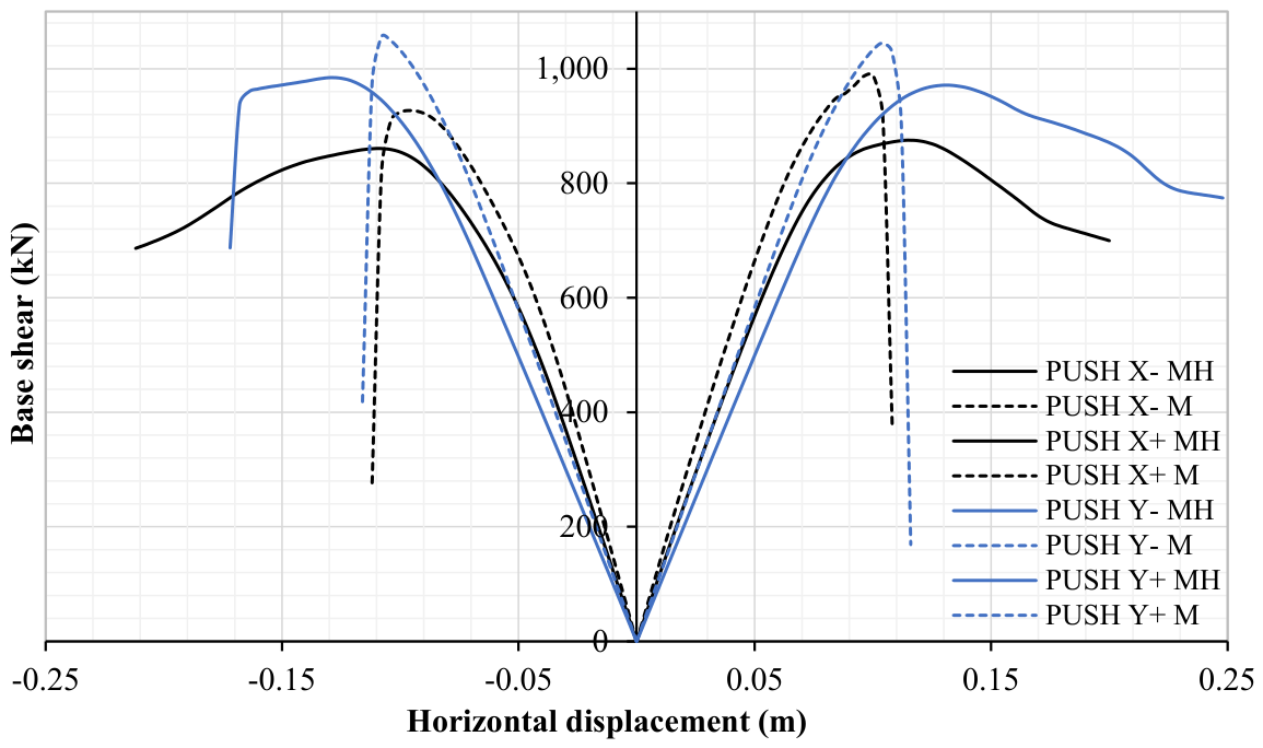
As described in Section 5.4, nonlinear static analyses have been performed in the two principal horizontal directions using the adopted lateral load patterns and displacement-control strategy. The resulting capacity curves, expressed in terms of base shear versus control-node displacement, are shown in Figure 17.
Figure 17.
Capacity curves obtained from nonlinear static analyses in the X and Y directions, considering the positive and the negative range and two lateral load patterns: mass-proportional (M) and mass-and-height-proportional (MH).
In the X direction, the positive and the negative range showed a similar order of lateral capacity, although differences were observed in the post-peak branch. For both orientations, the M pattern led to slightly higher peak base-shear values, but these were also associated with a more abrupt strength degradation after the maximum capacity was reached. By contrast, the proportional MH pattern produced smoother capacity curves and a more gradual post-peak response.
In the Y direction, the capacity curves reached slightly higher peak base-shear values than those obtained in the X direction. This response suggests that the baseline FEM does not present a single clearly weaker direction in terms of peak capacity. Yet, as in the X direction, the post-peak behaviour differed depending on the load pattern. The M pattern produced higher maximum values but sharper degradation, whereas the MH pattern provided a more progressive nonlinear response and a better-defined post-peak branch. The differences between the positive and the negative range may be related to the geometric asymmetry of the model, the distribution of openings and buttresses, and the influence of the adjacent Puerta del Perdón.
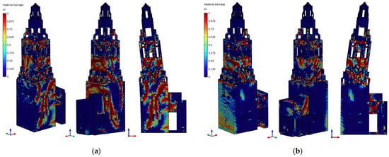
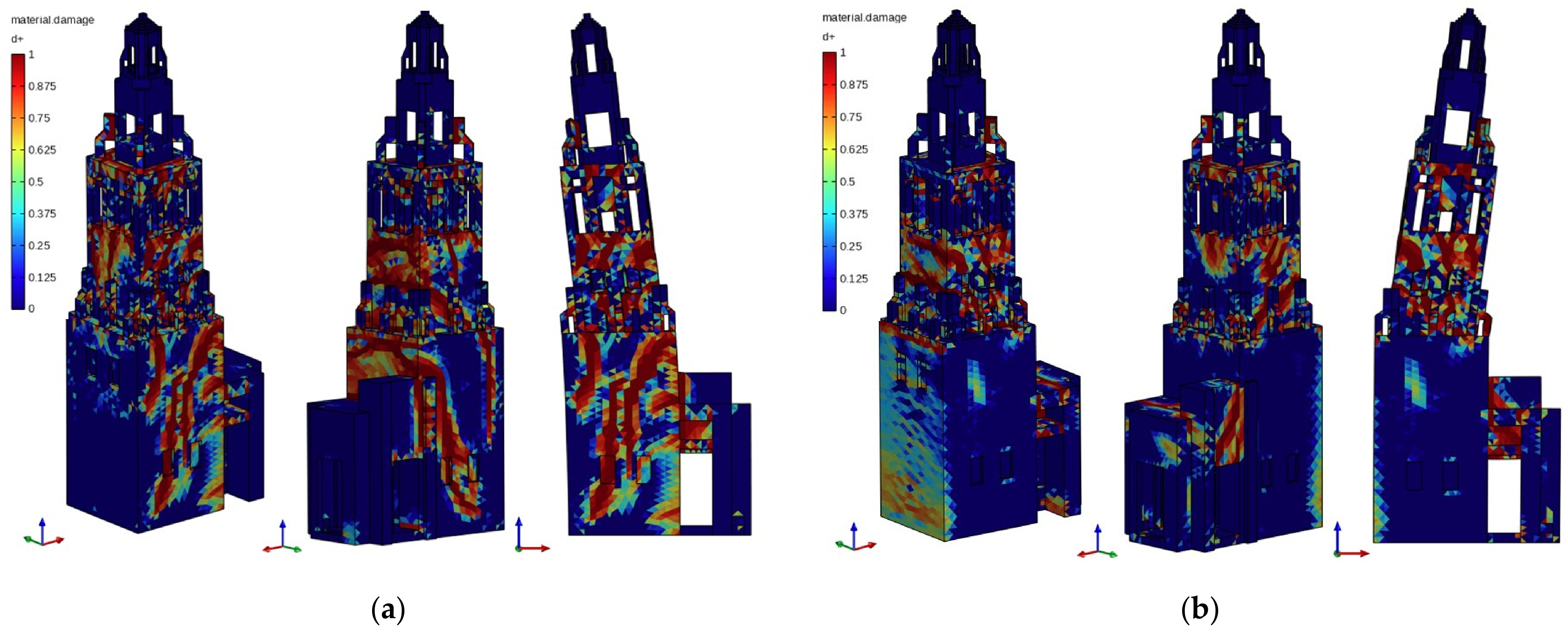
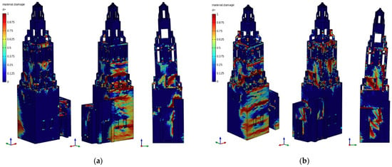
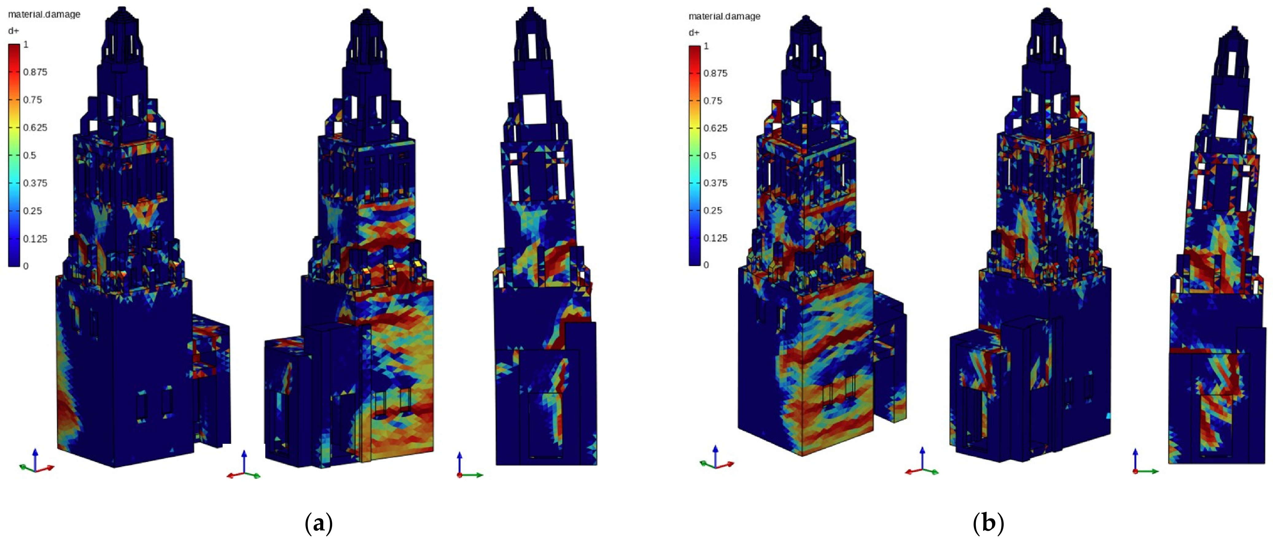
The numerical damage patterns obtained at the ultimate displacement of the analyses are shown in Figure 18 and Figure 19. Tensile damage has been plotted and analysed, since it is more significant than compressive damage. The damage was mainly concentrated around openings, at the transition between the massive shaft and the upper belfry bodies, and in areas where significant changes in geometry and stiffness occur. Local damage concentrations were also observed near the buttresses, the upper crowning elements and the connection region associated with the Puerta del Perdón. These results are consistent with the modelling uncertainties previously identified.
Figure 18.
Numerical damage patterns obtained in the X direction: (a) the negative and (b) the positive range.
Figure 19.
Numerical damage patterns obtained in the Y direction: (a) the negative and (b) the positive range.
These results identify the areas where tensile stress concentrations tend to develop under seismic loading, particularly around existing geometrical and stiffness discontinuities. The massive lower part of the tower shows limited damage, whereas damage becomes concentrated at the transition to the main tower shaft, where the structural configuration becomes more vulnerable. This area corresponds to a marked geometrical and stiffness discontinuity. Historically, buttresses were added at this level following the 1755 Lisbon earthquake, providing relevant historical context for the interpretation of the predicted damage pattern. The nonlinear static analyses provide an assessment of the global structural behaviour of the tower and identify areas where damage tends to concentrate under the assumptions adopted in this FEM.
7. Conclusions
7.1. Key Points
This paper has presented the development and assessment of a 3D FEM of the Bell Tower of the Mosque-Cathedral of Córdoba. The model provides a documented basis for the structural assessment of a highly complex masonry heritage structure, whose response is conditioned by its historical evolution, construction phases, internal geometry and boundary conditions. This study also shows the importance of explicitly identifying modelling uncertainties when developing numerical models of complex historical masonry structures.
The mesh sensitivity analysis showed similar peak lateral capacities for the 0.4, 0.5 and 0.6 m meshes, although differences were observed in the post-peak response, damage patterns and convergence behaviour. Finer meshes provided more detailed damage patterns but also produced sharper post-peak drops and less stable nonlinear branches. The 0.6 m mesh was selected for the subsequent modal and nonlinear static analyses, as it provided a reasonable compromise between geometric representation, numerical stability, convergence behaviour and computational efficiency.
The modal and nonlinear static analyses provided a first numerical interpretation of the global structural behaviour of the tower. The first two modes were mainly translational in the Y and X directions, with frequencies of 1.361 Hz and 1.508 Hz, respectively, while the third mode was mainly rotational, with a frequency of 4.062 Hz. The pushover analyses predicted peak base-shear values of around 850–1100 kN. The results indicated a comparable lateral capacity in the X and Y directions, although slightly higher peak values were obtained in the Y direction. No single clearly weaker direction was identified in terms of maximum capacity. However, relevant differences were observed in the post-peak response depending on the loading orientation and the adopted lateral load pattern.
The numerical damage patterns showed a clear relationship with the geometrical and constructive discontinuities previously identified in the uncertainty analysis. Tensile damage was mainly concentrated around openings, at the mid-height shaft, near the interface between the preserved Caliphal minaret and the later Christian masonry envelope, at the belfry level, around the upper buttresses and in the area associated with the Puerta del Perdón. Limited damage was predicted in the massive lower part of the tower, whereas damage increased at the transition to the main tower shaft, where a marked geometrical and stiffness discontinuity occurs. Buttresses were historically added at this level following the 1755 Lisbon earthquake. The largest lateral displacements were principally developed above the termination level of the Christian masonry envelope, indicating a change in the structural response between the lower and upper sectors of the tower.
The developed workflow—comprising historical and geometrical characterisation, explicit identification of modelling uncertainties, 3D reconstruction, FEM development, mesh sensitivity analysis, and modal and nonlinear static analyses—provides a methodological sequence that can be adapted to other multi-phase masonry towers. In this tower, the geometrical idealisation of the Caliphal core and Christian envelope, the inclusion of the Puerta del Perdón, the adopted homogeneous material properties, the perfect-bond and fixed-base assumptions, and the 0.6 m mesh represent case-specific modelling choices. These choices require reassessment according to the available evidence and structural configuration of each monument.
For conservation and structural monitoring, the predicted damage concentrations can help prioritise targeted inspections and crack surveys around openings, construction-phase transitions and the connection with the Puerta del Perdón. The numerical mode shapes can also inform the selection of measurement locations for future AVT campaigns aimed at identifying the tower’s dynamic properties and supporting model calibration. These applications can guide further investigation, while decisions on strengthening measures require site-specific experimental evidence and further assessment.
7.2. Limitations and Future Work
The results of this study should be interpreted within the assumptions adopted for the baseline FEM. In particular, the model uses homogeneous mechanical properties for the masonry and assumes perfect bonding between the different construction phases. FB boundary conditions are adopted, without explicitly including the foundations or soil–structure interaction (SSI). Material heterogeneity, local deterioration and existing defects and damage are not explicitly represented. The perfect-bond assumption has not been experimentally verified and should not be interpreted as evidence of the actual mechanical interaction between the different construction phases.
In addition, alternative interaction conditions between the Caliphal core and the Christian envelope have not been investigated, while the internal geometry of inaccessible areas remains partly uncertain. These assumptions may influence the predicted stiffness, modal response, lateral capacity and damage distribution. Future developments should investigate their influence through dedicated sensitivity analyses and incorporate a more detailed representation of the foundation system, adjacent structural constraints and SSI.
A further limitation is the absence of direct experimental calibration of the FEM. The comparisons with empirical formulations and experimental trends reported for comparable masonry towers provide a quantitative reference for the numerical modal response, but they do not constitute experimental validation of the model. Future work will therefore focus on the experimental characterisation of the dynamic response of the tower using OMA based on AVT measurements, followed by calibration of the FEM. AVT measurements are planned at the highest accessible level of the tower, at the top of the outer wall of the Christian masonry envelope, at the upper level of the Puerta del Perdón, and at one point in each adjoining loggia close to the tower. These measurements will provide experimental information to help assess the assumed monolithic behaviour of the Caliphal core and Christian envelope and the influence of the adjoining structures on the tower’s dynamic response.
Finally, a progressively refined and experimentally calibrated model could provide the basis for more advanced analyses, including nonlinear dynamic analyses and the assessment of alternative modelling scenarios. This would support a more robust evaluation of the seismic vulnerability of the tower and provide quantitative information for monitoring, conservation planning and the prioritisation of future interventions.
Author Contributions
The authors contributed to the conceptualisation and methodology. I.C.-d.-V.: software, validation, formal analysis, investigation, data curation, writing—original draft preparation, writing—review and editing, visualisation. E.R.-S.: software; writing—review and editing, supervision. A.M.-E.: resources, writing—review and editing, project administration, funding acquisition. All authors have read and agreed to the published version of the manuscript.
Funding
This research was funded by the R+D+i project “Metodología avanzada para la evaluación de la seguridad estructural y sísmica de edificios patrimoniales” (SAFE-HERITAGE), Grant ‘Proyecto PID2023-150771OB-I00’ funded by MICIU/AEI /10.13039/501100011033 and by FEDER, UE. The first author also acknowledges the financial support received from MICIN/AEI/10.13039/501100011033 and for FSE+ through the FPI PhD fellowship Ref. INV-PRE-III-2024-I-001.
Data Availability Statement
The geometrical model, mesh information, material parameters, analysis settings, and selected STKO/OpenSees input files are available from the corresponding author upon request, subject to the requirements associated with the ongoing research project and the protection of monument-related documentation.
Acknowledgments
The authors wish to acknowledge the support received from the Cathedral Chapter (Cabildo) of Córdoba.
Conflicts of Interest
The authors declare no conflicts of interest. The funders had no role in the design of this study; in the collection, analyses, or interpretation of data; in the writing of the manuscript; or in the decision to publish the results.
Abbreviations
The following abbreviations are used in this manuscript:
| 3D | Three-dimensional |
| CAD | Computer-aided design |
| FEM | Finite Element Model |
| STKO | Scientific ToolKit for OpenSees |
| OMA | Operational Modal Analysis |
| AVT | Ambient Vibration Testing |
| AE | Acoustic Emission |
| FB | Fixed base |
| SSI | Soil–structure interaction |
| M | Mass-proportional load pattern |
| MH | Mass-and-height-proportional load pattern |
| TC3D | 3D Tension–Compression Damage model |
References
- Lagomarsino, S.; Cattari, S. PERPETUATE guidelines for seismic performance-based assessment of cultural heritage masonry structures. Bull. Earthq. Eng. 2015, 13, 13–47. [Google Scholar] [CrossRef] [Scilit]
- Asteris, P.G.; Chronopoulos, M.P.; Chrysostomou, C.Z.; Varum, H.; Plevris, V.; Kyriakides, N.; Silva, V. Seismic vulnerability assessment of historical masonry structural systems. Eng. Struct. 2014, 62–63, 118–134. [Google Scholar] [CrossRef] [Scilit]
- Cattari, S.; Calderoni, B.; Caliò, I.; Camata, G.; de Miranda, S.; Magenes, G.; Milani, G.; Saetta, A. Nonlinear modeling of the seismic response of masonry structures: Critical review and open issues towards engineering practice. Bull. Earthq. Eng. 2022, 20, 1939–1997. [Google Scholar] [CrossRef] [Scilit]
- D’Altri, A.M.; Sarhosis, V.; Milani, G.; Rots, J.; Cattari, S.; Lagomarsino, S.; Sacco, E.; Tralli, A.; Castellazzi, G.; de Miranda, S. Modeling Strategies for the Computational Analysis of Unreinforced Masonry Structures: Review and Classification. Arch. Comput. Methods Eng. 2019, 27, 1153–1185. [Google Scholar] [CrossRef] [Scilit]
- Ivorra, S.; Pallarés, F.J. Dynamic investigations on a masonry bell tower. Eng. Struct. 2006, 28, 660–667. [Google Scholar] [CrossRef] [Scilit]
- Milani, G.; Clementi, F. Advanced Seismic Assessment of Four Masonry Bell Towers in Italy after Operational Modal Analysis (OMA) Identification. Int. J. Archit. Herit. 2021, 15, 157–186. [Google Scholar] [CrossRef] [Scilit]
- Romero-Sánchez, E.; Morales-Esteban, A.; Bento, R.; Navarro-Casas, J. Numerical modelling for the seismic assessment of complex masonry heritage buildings: The case study of the Giralda tower. Bull. Earthq. Eng. 2023, 21, 4669–4701. [Google Scholar] [CrossRef] [Scilit]
- Shehu, R. Implementation of pushover analysis for seismic assessment of masonry towers: Issues and practical recommendations. Buildings 2021, 11, 71. [Google Scholar] [CrossRef] [Scilit]
- Lourenço, P.B.; Van Hees, R.; Fernandes, F.; Lubelli, B. Characterization and damage of brick masonry. In Structural Rehabilitation of Old Buildings; Building Pathology and Rehabilitiation; Springer: Berlin/Heidelberg, Germany, 2013; pp. 109–130. [Google Scholar] [CrossRef] [Scilit]
- Gentile, C.; Saisi, A. Ambient vibration testing of historic masonry towers for structural identification and damage assessment. Constr. Build. Mater. 2007, 21, 1311–1321. [Google Scholar] [CrossRef] [Scilit]
- Degli Abbati, S.; Sivori, D.; Cattari, S.; Lagomarsino, S. Ambient vibrations-supported seismic assessment of the Saint Lawrence Cathedral’s bell tower in Genoa, Italy. J. Civ. Struct. Health Monit. 2024, 14, 121–142. [Google Scholar] [CrossRef] [Scilit]
- Verstrynge, E.; Lacidogna, G.; Accornero, F.; Tomor, A. A review on acoustic emission monitoring for damage detection in masonry structures. Constr. Build. Mater. 2021, 268, 121089. [Google Scholar] [CrossRef] [Scilit]
- Carpinteri, A.; Lacidogna, G. Damage evaluation of three masonry towers by acoustic emission. Eng. Struct. 2007, 29, 1569–1579. [Google Scholar] [CrossRef] [Scilit]
- Manuello, A.; Marmo, F.; Melchiorre, J. Investigating and monitoring central nave vaults of the Turin Cathedral with Acoustic Emissions and Thrust Network Analysis. Dev. Built Environ. 2024, 18, 100434. [Google Scholar] [CrossRef] [Scilit]
- Lourenço, P.B.; Rots, J.G.; Blaauwendraad, J. Two approaches for the analysis of masonry structures: Micro and macro-modeling. Heron 1995, 40, 313–340. [Google Scholar]
- Lourenco Paulo, B. Computational Strategy for Masonry Structures. Ph.D. Thesis, Delft University of Technology, Delft, The Netherlands, 1996. [Google Scholar]
- Ponte, M.; Bento, R.; Vaz, S.D. A Multi-Disciplinary Approach to the Seismic Assessment of the National Palace of Sintra. Int. J. Archit. Herit. 2021, 15, 757–778, Correction in Int. J. Archit. Herit. 2021, 15, 1081. [Google Scholar] [CrossRef] [Scilit]
- Castellazzi, G.; D’Altri, A.M.; de Miranda, S.; Chiozzi, A.; Tralli, A. Numerical insights on the seismic behavior of a non-isolated historical masonry tower. Bull. Earthq. Eng. 2017, 16, 933–961. [Google Scholar] [CrossRef] [Scilit]
- Degli Abbati, S.; D’Altri, A.M.; Ottonelli, D.; Castellazzi, G.; Cattari, S.; de Miranda, S.; Lagomarsino, S. Seismic assessment of interacting structural units in complex historic masonry constructions by nonlinear static analyses. Comput. Struct. 2019, 213, 51–71. [Google Scholar] [CrossRef] [Scilit]
- World Heritage Centre–UNESCO. Urban Heritage Atlas: Cultural Mapping of Historic Cities and Settlements; Historic Centre of Cordoba: Córdoba, Spain, 1984. [Google Scholar]
- Almagro Gorbea, A. Arquitectura de Al-Andalus: La Mezquita de Córdoba; Real Academia de Bellas Artes de San Fernando: Madrid, Spain, 2019. [Google Scholar]
- Ruiz Cabrero, G.; Rebollo Puig, G. Plan Director Mezquita-Catedral de Córdoba 2001; Cabildo Catedral de Córdoba: Córdoba, Spain, 2001. [Google Scholar]
- Ruiz Cabrero, G.; Rebollo Puig, G. Plan Director Mezquita-Catedral de Córdoba 2020; Cabildo Catedral de Córdoba: Córdoba, Spain, 2020. [Google Scholar]
- Ortiz-Cordero, R.; León Pastor, E.; Hidalgo Fernández, R.E. Proposal for the improvement and modification in the scale of evidence for virtual reconstruction of the cultural heritage: A first approach in the mosque-cathedral and the fluvial landscape of Cordoba. J. Cult. Herit. 2018, 30, 10–15. [Google Scholar] [CrossRef] [Scilit]
- Barrios Padura, A.; Barrios Sevilla, J.; García Navarro, J. Study of the Foundations of Cordoba’s Mosque Tower. In Proceedings of the REHAB 2014: International Conference on Preservation, Maintenance and Rehabilitation of Historic Buildings and Structures, Tomar, Portugal, 19–21 March 2014. [Google Scholar]
- Requena-Garcia-Cruz, M.V.; Romero-Sánchez, E.; Morales-Esteban, A. Contribution of the soil-structure interaction to the seismic behaviour of the Mosque-Cathedral of Córdoba. J. Build. Eng. 2025, 110, 113061. [Google Scholar] [CrossRef] [Scilit]
- Requena-Garcia-Cruz, M.V.; Romero-Sánchez, E.; López-Piña, M.P.; Morales-Esteban, A. Preliminary structural and seismic performance assessment of the Mosque-Cathedral of Cordoba: The Abd al-Rahman I sector. Eng. Struct. 2023, 291, 116465. [Google Scholar] [CrossRef] [Scilit]
- Morales Esteban, A.; Vázquez Boza, M. Proyecto I+D+i: Proyecto para un Patrimonio Cultural Resiliente a los Terremotos. Casos de Estudio: La Mezquita de Córdoba y la Giralda de Sevilla; US-1380730, Proyectos I+D+i FEDER Andalucía 2014–2020; Universidad de Sevilla: Sevilla, Spain, 2023. [Google Scholar]
- Hernández Giménez, F. El Alminar de Abd al-Rahman III en la Mezquita Mayor de Córdoba. Génesis y Repercusiones; Patronato de la Alhambra y el Generalife: Granada, Spain, 1975. [Google Scholar]
- Ortiz Cordero, R. La Mezquita-Catedral de Córdoba. Metodología de Trabajo para Reconstrucciones Virtuales. Ph.D. Thesis, Universidad de Córdoba, Córdoba, Spain, 2018. [Google Scholar]
- Cuerda-del-Valle, I.; Romero-Sánchez, E.; Morales-Esteban, A. A Vertical Palimpsest. Construction and structural evolution of the Bell Tower of the Mosque-Cathedral of Córdoba. Restauro Archeol. 2025, 33, 44–55. [Google Scholar] [CrossRef] [Scilit]
- Requena-Garcia-Cruz, M.V.; Romero-Sánchez, E.; Morales-Esteban, A. Dynamic performance of the Mosque-Cathedral of Córdoba under different earthquake scenarios: The Abd al-Rahman I sector. J. Build. Eng. 2023, 79, 107853. [Google Scholar] [CrossRef] [Scilit]
- Perez Lopez, R.; Sánchez Hernampérez, A.; Silva, P.; Elez, J.; Giner Robles, J.L.; Rodriguez Pascua, M.A.; Roquero, E.; Bardají Azcárate, T.; Sanchez, Y. Córdoba, 21 Septiembre 1589: ¿Terremoto y/o Tempestad? Evidencias Arqueosismológicas. In Proceedings of the IV Reunión Ibérica Sobre Fallas Activas y Paleosismología (Iberfault 2022), Teruel, Spain, 7–10 September 2022. [Google Scholar]
- Borri, A.; Corradi, M.; De Maria, A. The failure of masonry walls by disaggregation and the masonry quality index. Heritage 2020, 3, 1162–1198. [Google Scholar] [CrossRef] [Scilit]
- Szabó, S.; Funari, M.F.; Lourenço, P.B. Masonry patterns’ influence on the damage assessment of URM walls: Current and future trends. Dev. Built Environ. 2023, 13, 100119. [Google Scholar] [CrossRef] [Scilit]
- Petracca, M.; Candeloro, F.; Camata, G. STKO User Manual; AADEA Software Technology: Pescara, Italy, 2017. [Google Scholar]
- Petracca, M.; Pelà, L.; Rossi, R.; Zaghi, S.; Camata, G.; Spacone, E. Micro-scale continuous and discrete numerical models for nonlinear analysis of masonry shear walls. Constr. Build. Mater. 2017, 149, 296–314. [Google Scholar] [CrossRef] [Scilit]
- Petracca, M.; Pelà, L.; Rossi, R.; Oller, S.; Camata, G.; Spacone, E. Multiscale computational first order homogenization of thick shells for the analysis of out-of-plane loaded masonry walls. Comput. Methods Appl. Mech. Eng. 2017, 315, 273–301. [Google Scholar] [CrossRef] [Scilit]
- Ministero delle Infrastrutture e dei Trasporti. Istruzioni per l’applicazione dell’«Aggiornamento delle “Norme Tecniche per le Costruzioni”» di cui al Decreto Ministeriale 17 Gennaio 2018; Circolare 21 gennaio 2019, n. 7 C.S.LL.PP; Gazzetta Ufficiale della Repubblica Italiana, Serie Generale n. 35, Supplemento Ordinario n. 5, 11 febbraio 2019; Ministero delle Infrastrutture e dei Trasporti: Roma, Italy, 2019.
- Ministerio de Fomento. Código Técnico de la Edificación. Documento Básico. Seguridad Estructural: Fábrica (SE-F); Ministerio de Fomento: Madrid, Spain, 2019.
- Kržan, M.; Gostič, S.; Cattari, S.; Bosiljkov, V. Acquiring reference parameters of masonry for the structural performance analysis of historical buildings. Bull. Earthq. Eng. 2015, 13, 203–236. [Google Scholar] [CrossRef] [Scilit]
- UNE-EN 1998-1; Eurocode 8: Design of Structures for Earthquake Resistance. Part 1: General Rules, Seismic Actions and Rules for Buildings. CEN (European Committee for Standardization/Comité Européen de Normalisation): Brussels, Belgium, 2022.
- UNE-EN 1998-3; Eurocode 8: Design of Structures for Earthquake Resistance. Part 3: Assessment and Retrofitting of Buildings. CEN (European Committee for Standardization/Comité Européen de Normalisation): Brussels, Belgium, 2018.
- Diaferio, M.; Foti, D.; Potenza, F. Prediction of the fundamental frequencies and modal shapes of historic masonry towers by empirical equations based on experimental data. Eng. Struct. 2018, 156, 433–442. [Google Scholar] [CrossRef] [Scilit]
- Shakya, M.; Varum, H.; Vicente, R.; Costa, A. Empirical Formulation for Estimating the Fundamental Frequency of Slender Masonry Structures. Int. J. Archit. Herit. 2016, 10, 55–66. [Google Scholar] [CrossRef] [Scilit]
- Ministerio de Fomento. Norma de Construcción Sismorresistente: Parte General y Edificación (NCSE-02); Ministerio de Fomento: Madrid, Spain, 2009.
- Gentile, C.; Guidobaldi, M.; Saisi, A. One-year dynamic monitoring of a historic tower: Damage detection under changing environment. Meccanica 2016, 51, 2873–2889. [Google Scholar] [CrossRef] [Scilit]
- Bartoli, G.; Betti, M.; Giordano, S. In situ static and dynamic investigations on the “Torre Grossa” masonry tower. Eng. Struct. 2013, 52, 718–733. [Google Scholar] [CrossRef] [Scilit]

Disclaimer/Publisher’s Note: The statements, opinions and data contained in all publications are solely those of the individual author(s) and contributor(s) and not of MDPI and/or the editor(s). MDPI and/or the editor(s) disclaim responsibility for any injury to people or property resulting from any ideas, methods, instructions or products referred to in the content. |
© 2026 by the authors. Licensee MDPI, Basel, Switzerland. This article is an open access article distributed under the terms and conditions of the Creative Commons Attribution (CC BY) license.