


Abstract
Steel square hollow section (SHS) members are widely used in buildings, bridges, and industrial structures due to their high strength-to-weight ratio and torsional resistance. In steel SHS members, crack-like initial defects may occur due to environmental effects, especially corrosion, and these defects may adversely affect their performance. Although the cyclic behavior and stability of SHS members have been studied, previous investigations have mainly focused on uncracked members, while the response of initially cracked SHS columns under combined axial and cyclic lateral loading remains insufficiently understood. In this study, the lateral cyclic performance of steel SHS columns with initial crack defects was investigated, and a local retrofit strategy using CFRP wrapping was proposed. Eighteen specimens with wall thicknesses of and 4 mm were tested under cyclic lateral loading combined with nominal axial load ratios of 0, , and . Failure of the 2 mm cracked specimens was governed by local buckling, whereas the 4 mm cracked specimens exhibited fracture and combined fracture-local buckling. 2D-DIC analysis showed strain localization around the crack tips. Initial crack defects reduced the lateral load capacity by up to and for the 2 and 4 mm groups, respectively, whereas CFRP-wrapped cracked specimens exhibited capacities up to and higher than the corresponding uncracked specimens. This study provides a better understanding of the interaction among initial crack defects, section slenderness, axial load ratio, and local CFRP wrapping in the lateral cyclic behavior of steel SHS columns, thereby contributing to the further development of the theory of steel structures.
1. Introduction
Steel square hollow sections (SHS) are widely used in civil engineering structures such as building frames, bridges, industrial facilities, and light steel frames. Researchers have investigated the cyclic performance of SHS members to better understand and prevent stability-related failures [1]. In engineering practice, member stability and limit states are generally evaluated using design specifications such as ANSI/AISC 360-22 and Eurocode 3 [2,3]. However, the actual cyclic behavior of SHS members may be more complex than idealized representations, particularly when initial imperfections are present [4,5,6].
Local buckling is one of the critical limit states for thin-walled SHS members because the flat plate elements of the section may undergo local out-of-plane deformation [7,8]. This behavior becomes more pronounced when the width-to-thickness ratio is high. Misiūnaitė et al. [9] showed that increased slenderness in cold-formed steel tubular members increases the severity of local deformation and stress concentration in the flat plate elements. Wan et al. [10] investigated local buckling in hollow steel box columns and obtained full-field strain mapping using 2D and 3D digital image correlation (DIC). Cosgun [11] suggested a stiffening technique to enhance the local buckling resistance of cold-formed square hollow sections.
Steel SHS members may contain local defects such as notch or crack-like discontinuities originating from manufacturing, material discontinuities, accidental damage, cutting, drilling, welding, corrosion, or chemical exposure. Such defects have a negative influence on the performance of the structure [12,13,14]. Corrosion of the structural steel is one of the most common and important causes of such defects. Recent studies indicate that corrosion is more severe in marine, coastal, and humid environments due to the combined effects of humidity, chloride deposition, temperature variations, and wet–dry cycles [15,16]. Zhang et al. reported that thickness loss and localized corrosion pits have an adverse effect on the strength and ductility of the structural steel [17]. Kong et al. conducted an accelerated corrosion test, and they reported that the mechanical properties of Q235 steel, such as elastic modulus, yield strength, ultimate strength, and fracture strain, were adversely affected by corrosion [18]. Additionally, studies at the structural-member level have shown that corrosion-induced cross-sectional loss and corrosion pits in steel SHS short columns can decrease their ultimate bearing capacity [19].
In the literature, several strengthening alternatives to CFRP wrapping are available for retrofitting damaged steel structural members. The conventional alternatives include strengthening with steel hoops, welding the damaged region, or replacing the damaged member(s) if possible. However, each of these conventional alternatives has its own difficulties. Moreover, these alternatives are still prone to corrosive environments. Gao et al. investigated these alternatives and reported labor, material, and time costs [20]. In accordance with their study, the total cost of these alternatives is relatively higher than the cost of CFRP wrapping. In this context, the advantages of CFRP outweighed those of other conventional methods. Besides that, Duan et al. summarize Basalt Fiber-Reinforced Polymer (BFRP) as an environmentally friendly strengthening material [21]. Different researchers have conducted successful studies using BFRP to strengthen corroded steel members, and they reported that the ductility of BFRP is higher than that of other FRP materials [22,23]. However, the tensile strength of BFRP has been reported to be approximately 30% of that of CFRP [22]. Therefore, CFRP remains a considerable method for strengthening structural members when high tensile strength is required.
Ghaemdoust et al. [24] experimentally and numerically investigated steel SHS short columns with structural defects to evaluate their structural performance and the effectiveness of CFRP wrapping. Karimian et al. [25] experimentally and numerically investigated concrete-filled circular hollow section (CHS) short columns with notch defects under axial compression and examined their strengthening using CFRP wrapping. Similarly, Yousefi et al. [13] investigated CFRP strengthening of corroded CHS steel columns under axial loading. These studies showed that these initial defects have a negative impact on structural performance, while CFRP strengthening can improve the structural performance of such structures. The effectiveness of CFRP wrapping depends on the number of CFRP layers and fiber orientation [20,26].
Recent studies have provided a further evaluation of the cyclic performance and stability of steel hollow-section members. Chen et al. developed a strain-based methodology to predict local buckling of structural steel members [27]. Njiru and Mamaghani conducted a numerical study on the design of thin-walled stiffened steel square box columns under seismic loading [28]. Yamada et al. conducted an analytical study to evaluate the seismic performance of steel SHS columns [29]. Weng et al. provided a further investigation of the influence of initial imperfections on the seismic behavior of steel hollow structural section (HSS) columns [30]. Demir et al. conducted an experimental and numerical investigation of steel circular and square hollow section braces under far-field and near-fault ground motions [31]. Buckling and fracture-related failures were examined in this study. Studies on the cyclic behavior of concrete-filled steel tubular members were conducted by different researchers [32,33]. Further experimental studies were conducted to understand the local buckling of steel SHS members under cyclic loading [34,35]. Cosgun and Akcan numerically and experimentally investigated the behavior of perforated steel SHS columns under eccentric compression [36].
Although the performance and strengthening of steel SHS elements with notches, cracks, or corrosion-related defects have been examined in the literature, most available studies have generally focused on axial compression, bending, impact, or fatigue loading. To the best of the authors’ knowledge, the lateral cyclic performance of cracked steel SHS columns under combined axial and cyclic lateral loading has not yet been systematically investigated. Based on the available literature, it is difficult to discuss the seismic performance and strengthening of such damaged members under cyclic loading conditions. These defects may adversely affect the lateral cyclic behavior of steel SHS members.
The objectives of this study are to experimentally investigate the adverse effect of the initial crack defects on the lateral cyclic performance of steel SHS columns and to mitigate this effect by using local CFRP wrapping. Accordingly, this research investigates the effects of wall thickness, nominal axial load ratio, initial crack defect, and local CFRP wrapping on the lateral cyclic performance of cracked steel SHS columns. The motivation of this study is to provide a better understanding of the lateral cyclic performance of initially cracked steel SHS columns and their local retrofit via CFRP wrapping. In the scope of this study, 18 steel SHS columns were experimentally tested under quasi-static cyclic lateral loading combined with three axial load levels corresponding to 0, 15, and of the nominal axial capacity of the columns. The axial load ratios were determined in accordance with ANSI/AISC 360-22 [2], while the cyclic loading protocol was applied in accordance with ANSI/AISC 341-22 [37]. The experimental program included nine slender and nine non-slender steel SHS columns to evaluate the influence of cross-sectional slenderness. Three specimen configurations were considered: uncracked columns, cracked columns, and cracked columns strengthened using CFRP wrapping. The horizontal notches, with V-shaped ends, were introduced within the expected plastic hinge region to simulate an initial crack defect. Cyclic loading was applied in a direction that caused repeated opening and closing of the crack, thereby representing a critical loading condition for the cracked member. The strain distribution around the crack region was evaluated using two-dimensional DIC implemented through the open-source Ncorr software [38] in MATLAB R2024b [39].
2. Experimental Program
The experimental study consisting of 18 steel SHS columns was carried out to investigate the effects of initial crack defects, cross-sectional slenderness, nominal axial load ratio, and local CFRP wrapping on the lateral cyclic performance of steel SHS column test specimens. Notches were introduced on one face of the cracked specimens within the expected plastic hinge region to simulate an initial crack defect, and cyclic loading was applied in the crack opening and closing directions. Thus, a critical loading condition for the cracked specimens was investigated. The uncracked specimens were used as control specimens to investigate the influence of the initial crack defect and the CFRP wrapping on the lateral cyclic performance.
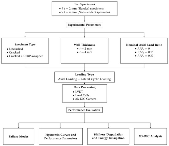
The flowchart of the experimental program, including the experimental variables, data processing, and performance evaluation, is given in Figure 1.
Figure 1.
Flowchart of the experimental variables, loading type, data processing, and performance evaluation.
2.1. Test Specimens and Loading Procedure
In the scope of the experimental study, 18 steel SHS columns were tested. The tested specimens were classified into two main groups: 9 columns with slender cross-sections (nominal wall thickness mm) and 9 columns with non-slender cross-sections (nominal wall thickness mm). For both thicknesses, under lateral cyclic loading, the three axial load ratios, the effect of initial cracks, and the CFRP wrapping condition were examined in detail.
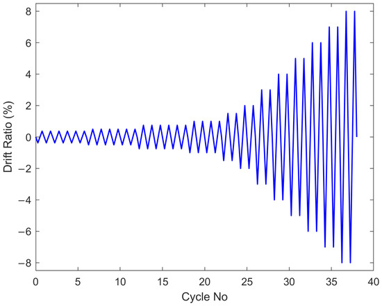
The nominal axial load capacities of the steel SHS column specimens were calculated based on the ANSI/AISC 360-22 specification [2]. In the nominal axial load capacity calculations, nominal material properties ( MPa and GPa) and nominal wall thickness values ( mm and mm) were used. The member length used in the nominal axial capacity calculations was mm. The parameters used for the cross-sectional slenderness classification and nominal axial capacity calculations are summarized in Table 1. The nominal axial load ratios and corresponding load values applied to each wall thickness group are summarized in Table 2. The lateral cyclic loading protocol was adopted from the ANSI/AISC 341-22 seismic provisions [37], and the loading history is provided in Figure 2.
Table 1.
Cross-sectional slenderness classification and nominal axial capacity parameters.
Table 2.
Nominal axial load ratios and corresponding applied axial load values.
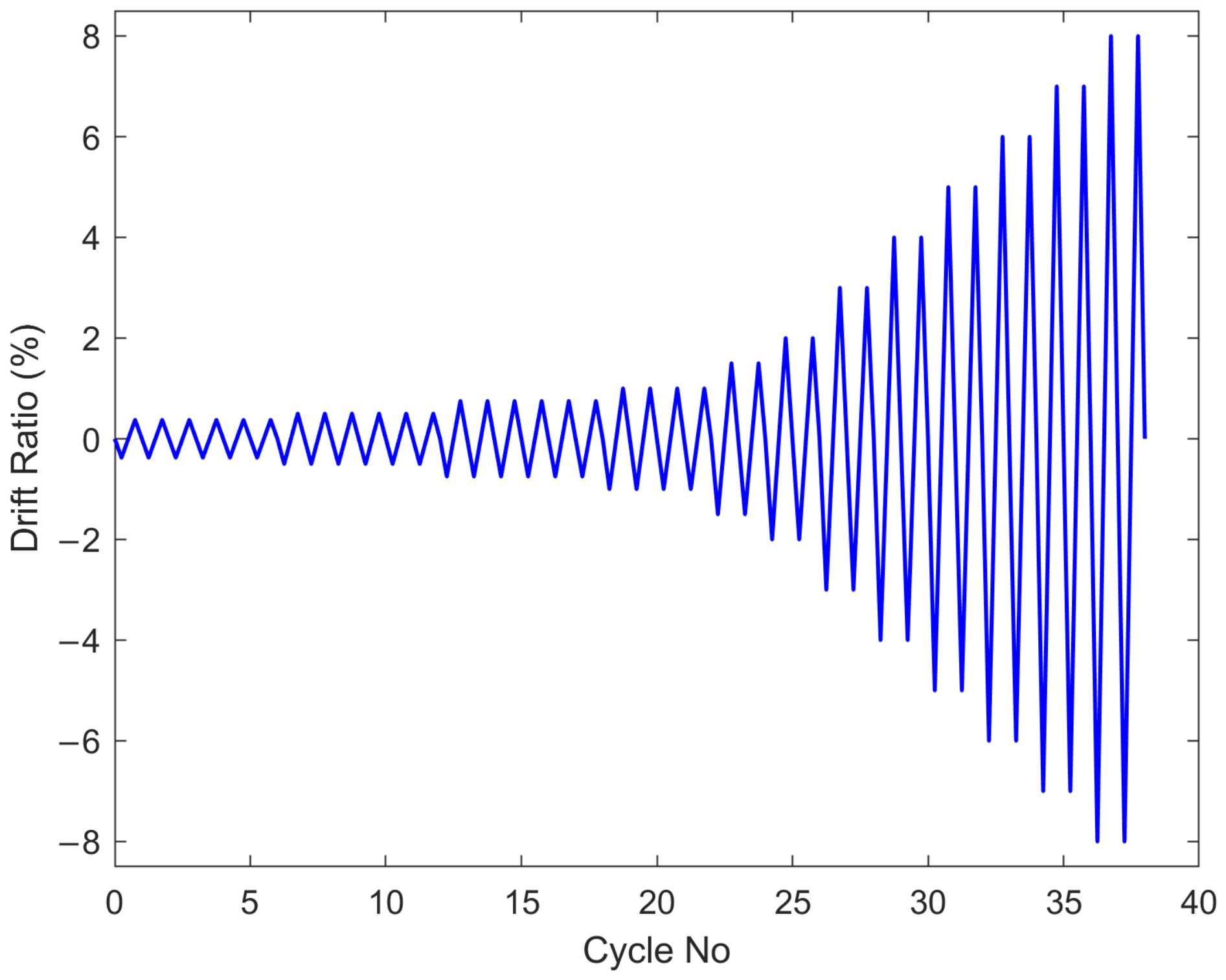
Figure 2.
ANSI/AISC 341-22 loading protocol [37].
ANSI/AISC 341-22 [37] provides a standardized cyclic loading history that is commonly used to evaluate the performance of the steel structural components or connections. The protocol consists of repeated and progressively increasing cycles based on drift angles, allowing the development of progressive damage accumulation and failure mechanisms. This cyclic loading protocol has been widely adopted in recent experimental studies in steel structures [40,41,42,43]. Therefore, the ANSI/AISC 341-22 cyclic loading protocol was selected in this study to follow a commonly used cyclic loading protocol and to conduct a repeatable study for future research.
For each group of wall thickness and axial load ratio, three specimen configurations were experimentally tested: an uncracked control specimen, a specimen with an initial crack defect, and a cracked specimen wrapped with four layers of plain-weave (–) CFRP fabric. The CFRP wrapping length was 18 cm. Prior to CFRP application, the steel surface was cleaned. Sikadur 330, a two-component thixotropic epoxy adhesive, was used to bond the CFRP fabric to the steel surface. By testing the uncracked specimens as a control group, the presence of initial crack defects and the effect of CFRP wrapping on the structural performance of cracked columns were examined in detail. Test IDs and specimen explanations for each wall thickness group are summarized in Table 3 and Table 4.
Table 3.
Specimen IDs for slender sections.
Table 4.
Specimen IDs for non-slender sections.
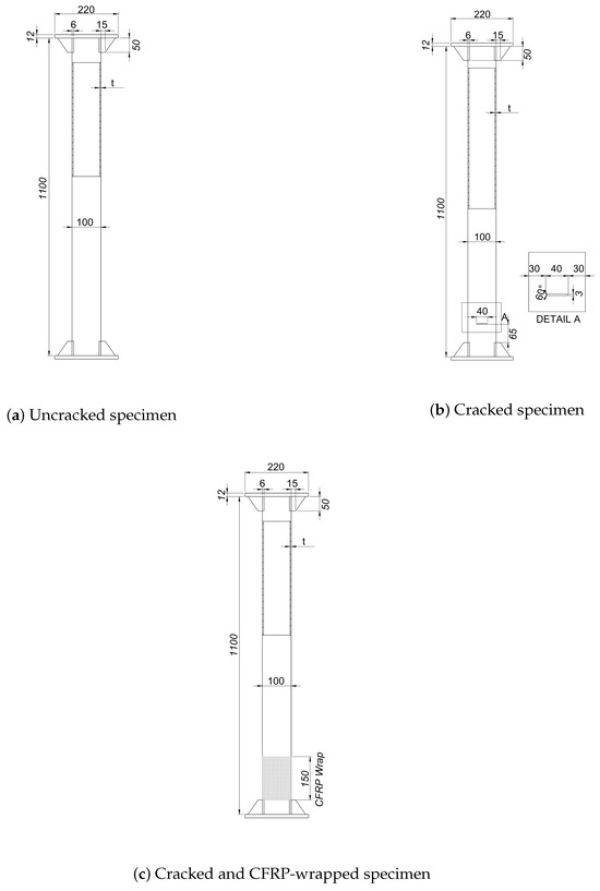
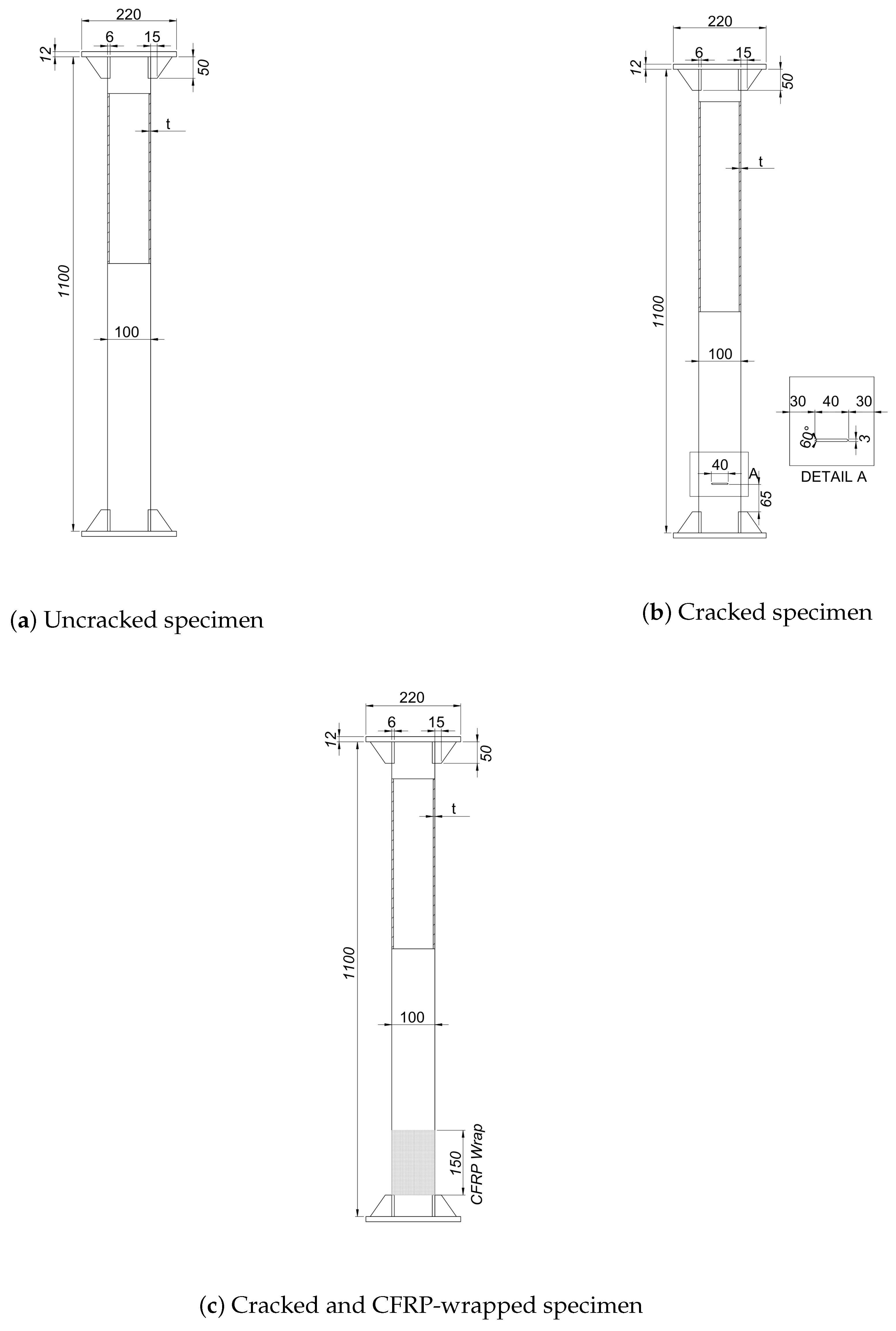
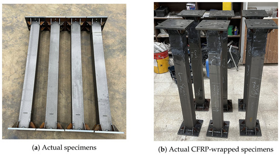
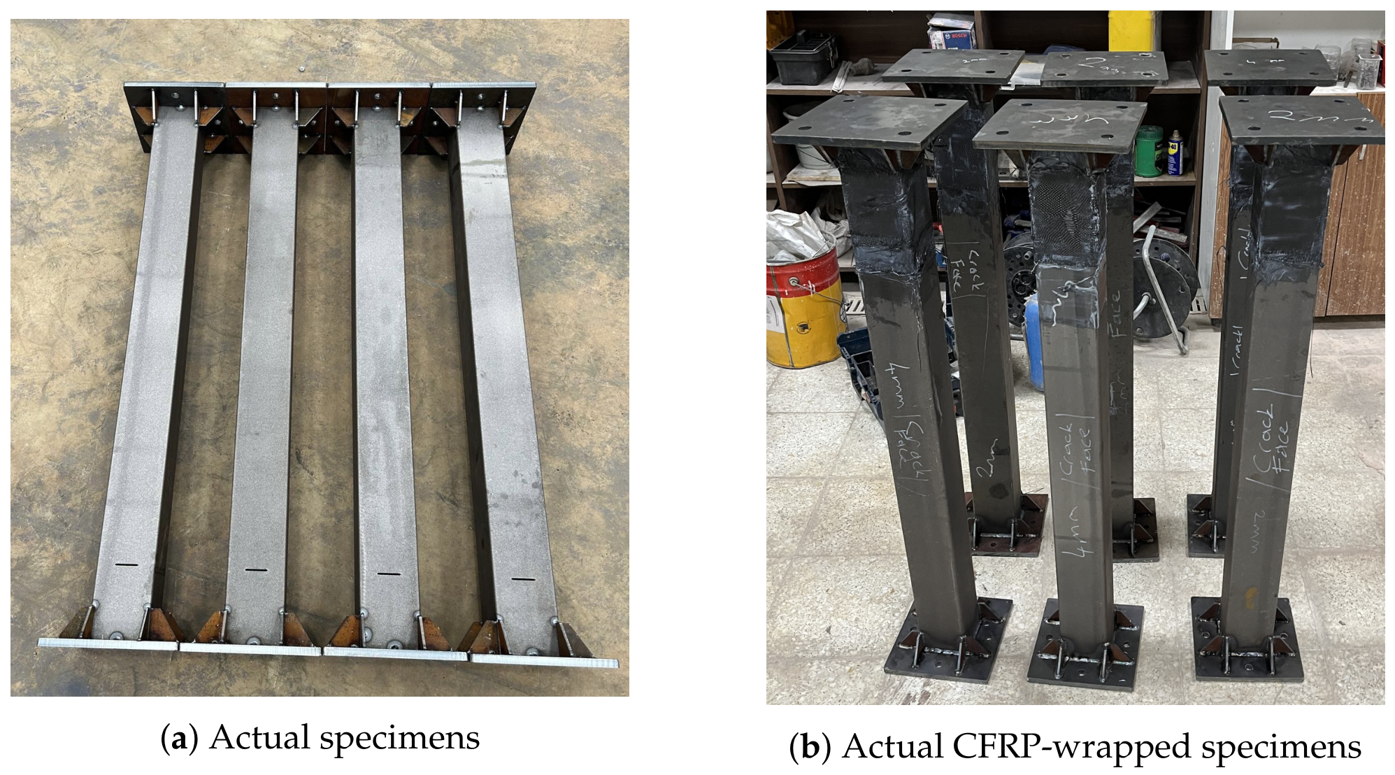
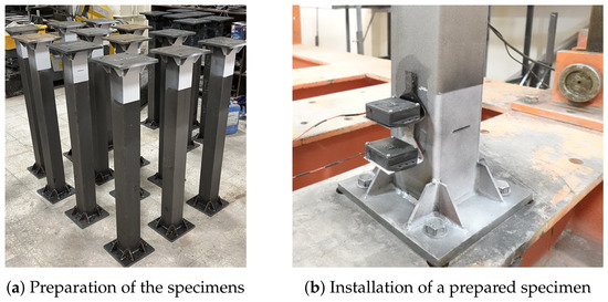
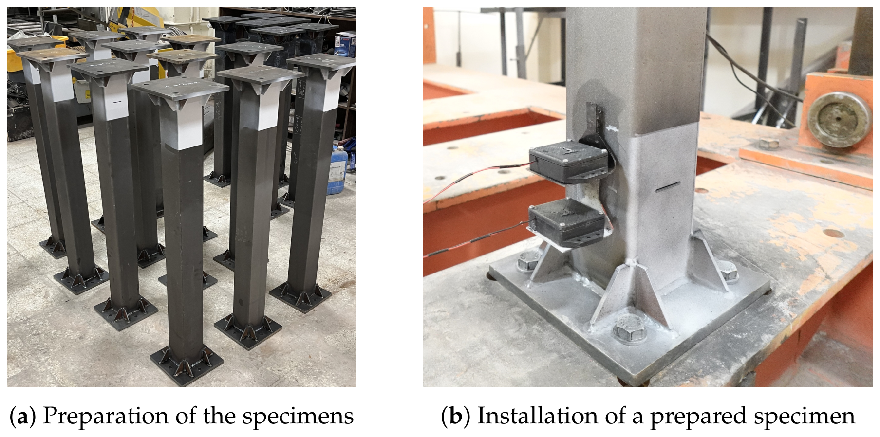
The full-scale steel SHS column specimens were fabricated from commercially available mm and mm profiles. The length of all the columns was 1100 mm, but the lateral load was applied at a height of 900 mm from the base. The horizontal notch was introduced on one face of each cracked specimen by laser cutting and had a length of 40 mm, an opening width of 3 mm, and V-shaped ends. Dimensions and detailed drawings of specimens are given in Figure 3. At the bottom of the columns, there were square 220 mm × 220 mm base plates, and using four M16 bolts, the base plates were anchored at the four corners to the rigid base of the test frame. At the top of the columns, there was a 220 mm × 220 mm top plate to apply axial loadings. The base plate and top plate were welded to the column, and a total of eight stiffeners were used, with four welded between the corners of the column and the base plate and four between the corners of the column and the top plate. Fabricated column test specimens and CFRP-wrapped test specimens are given in Figure 4.
Figure 3.
Geometry and details of the steel SHS column specimens: all dimensions are in mm; t denotes the wall thickness.
Figure 4.
Fabricated actual steel SHS column specimens: (a) Cracked specimens and (b) CFRP-wrapped cracked specimens.
2.2. Material Properties
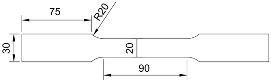
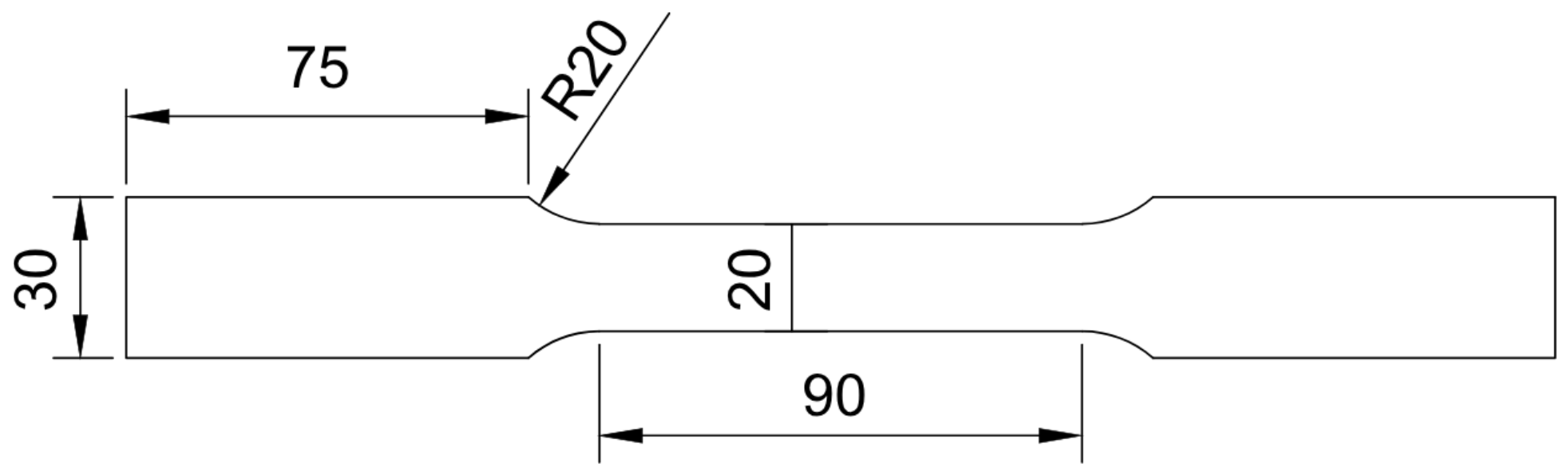
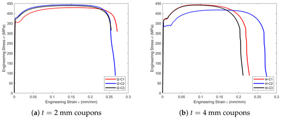
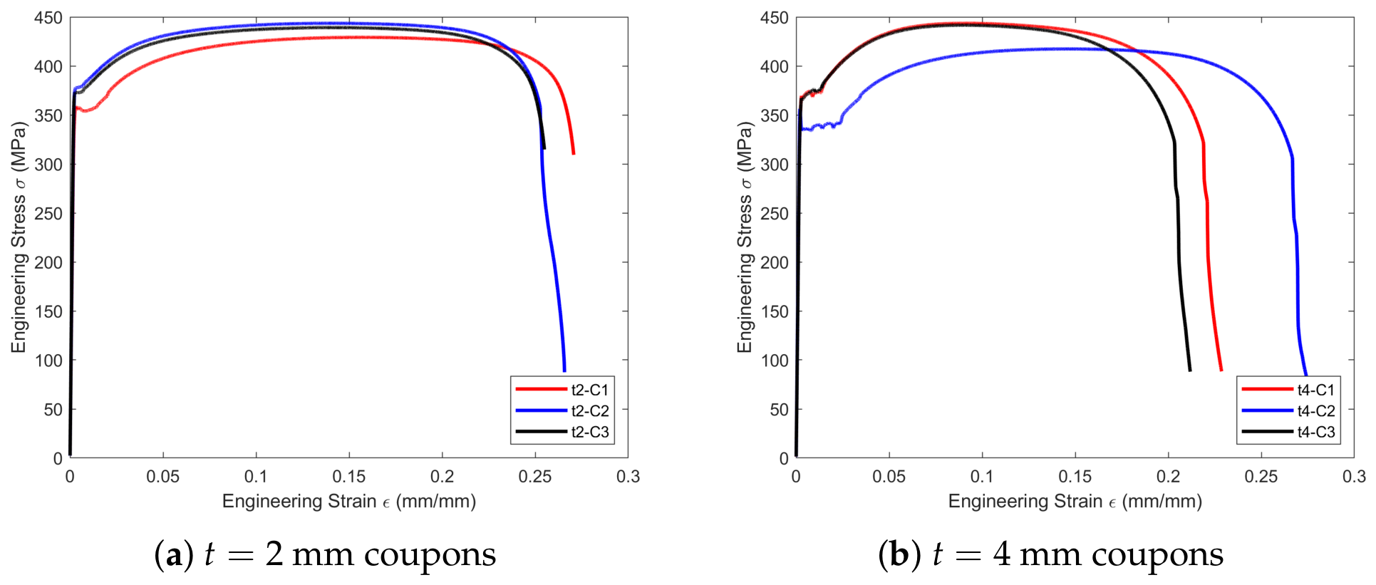
The column specimens were made of S235JR-grade steel. For each wall thickness, all profiles were obtained from a single production batch. Three tensile coupon specimens were prepared from each of the 2 mm and 4 mm profiles. Tensile tests were conducted according to EN ISO 6892-1 [44] to determine the actual mechanical properties of the steel. The tensile coupon specimens were extracted by laser cutting from the as-received surfaces of the column profiles. The tensile coupon specimens had a gauge length of 80 mm, a parallel length of 90 mm, a width of 20 mm, a transition radius of 20 mm, and a grip width of 30 mm. Dimensions of the coupons are given in Figure 5. Tensile tests were conducted using a Zwick/Roell (Z250, ZwickRoell GmbH & Co. KG, Ulm, Germany) universal testing machine with an accuracy class of . A clip-on extensometer was used during the tensile tests. The strain rate during the tension was s−1 up to the yield point and yield range, while the test speed was s−1 after yielding. Table 5 and Table 6 summarize the measured properties of the tensile coupon specimens for 2 mm and 4 mm profiles, respectively. The and values given in the tables are the measured thickness and width of the specimens, respectively. Additionally, the engineering stress–strain curves of the coupons are given in Figure 6.
Figure 5.
Dimensions of tensile coupon specimens (all dimensions are in mm).
Table 5.
Mechanical properties of mm coupons.
Table 6.
Mechanical properties of mm coupons.
Figure 6.
Engineering stress–strain curves for coupons.
Sikadur 330 epoxy resin, a structural adhesive, was used to bond CFRP fabrics to the surfaces of the column specimens. Mechanical properties of Sikadur 330 were obtained from the manufacturer’s technical data sheet [45]. Bidirectional (–) CFRP fabric was used to retrofit cracked columns, and a technical data sheet was provided from the manufacturer [46]. The CFRP-strengthened specimens were cured for at least two weeks after the application of the CFRP wrapping before testing. Technical information of Sikadur 330 and CFRP fabric is given in Table 7 and Table 8.
Table 7.
Mechanical properties of Sikadur-330 structural adhesive [45].
Table 8.
Mechanical properties of the CFRP fabric [46].
2.3. Test Setup
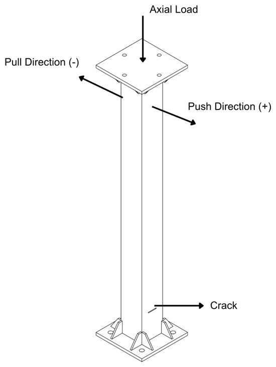
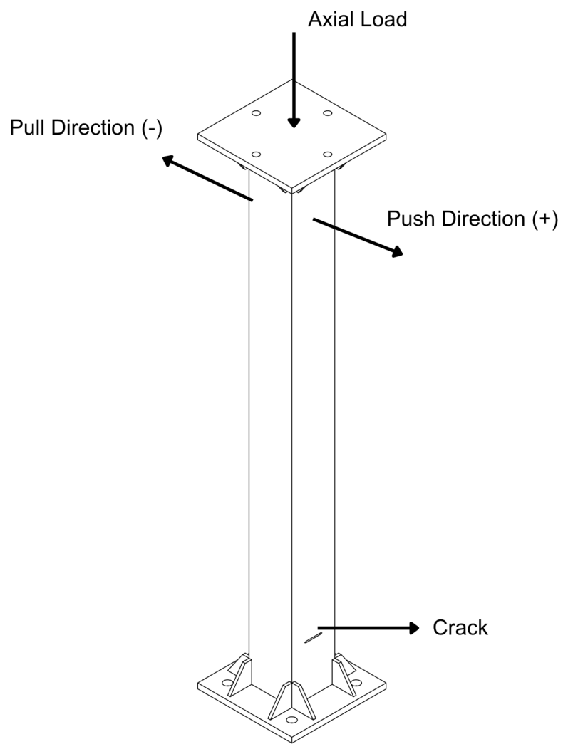
The experimental setup was designed to test steel SHS columns under combined axial loading and displacement-controlled cyclic lateral loading. The test specimens were fixed to the rigid base of the test frame through their base plates using four M16 bolts. The cyclic lateral loading direction is defined based on the orientation of the crack. In cracked columns, the crack is introduced only on one face of the column. Crack opening direction is the negative pull direction, and crack closure direction is the positive push direction. Loading directions based on crack orientation are shown in Figure 7. This definition was used consistently in the presentation of the results of the experimental work.
Figure 7.
Axial and cyclic lateral loading directions based on crack orientation.
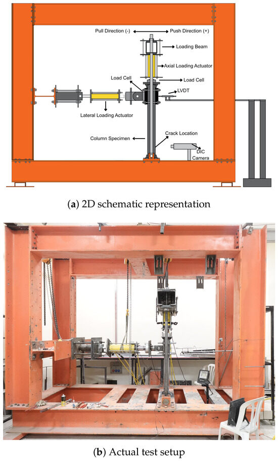
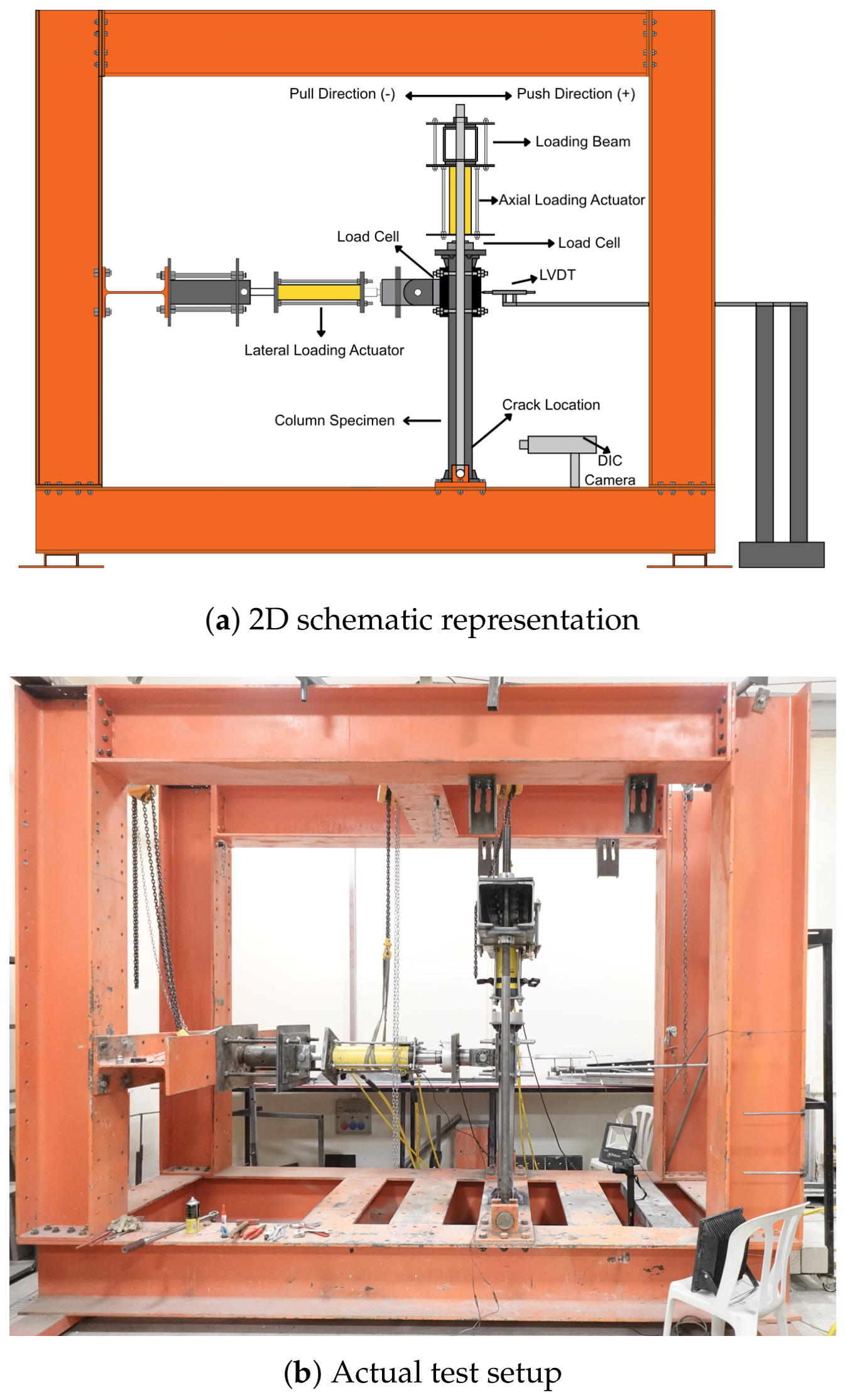
Axial loading was directly applied to the top plates of the test specimens, whereas lateral loading was applied at a height of 900 mm from the base of the specimen, and lateral displacement response was measured at the same height using a linear variable differential transformer (LVDT). The 2D schematic representation and actual test setup are provided in Figure 8. Lateral and axial load data were recorded using load cells. Both load cells and LVDT data were recorded at a 10 Hz sampling rate.
Figure 8.
Schematic and actual test setup.
2.4. Data Processing
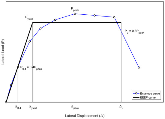
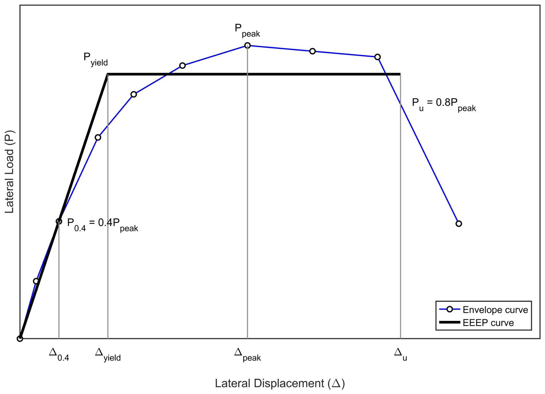
Hysteresis responses alone are not sufficient to evaluate the cyclic performance of the specimens in detail. Therefore, the peak responses of the first cycle at each drift ratio were determined and combined to obtain backbone curves from the cyclic load–displacement curves. Using these backbone curves, equivalent energy elastic-plastic (EEEP) curves were obtained according to ASTM E2126 [47]. The EEEP idealization specified in ASTM E2126 and its associated parameters are illustrated in Figure 9 [47]. The and values, corresponding to the peak load and the associated displacement, were determined for each test specimen under combined loading. In addition, the and values, corresponding to the yield load and yield displacement, were computed from the EEEP idealization. The effective stiffness, , and ductility ratio, D, were calculated using Equations (1) and (2), respectively.
Figure 9.
Illustration of the ASTM E2126 EEEP idealization and its associated parameters, adapted from ASTM E2126-11 [47].
Here, represents the peak lateral load, and is the corresponding displacement. represents of , and is the corresponding displacement on the ascending portion of the backbone curve. Similarly, represents of , and is the corresponding displacement on the descending portion of the backbone curve.
In addition to the backbone energy, cumulative energy dissipation is an important parameter to evaluate the seismic performance of a structural element or a system. Cumulative energy dissipation is a key parameter in this experimental study since it was used to assess the total energy dissipated by the uncracked, cracked, and CFRP-wrapped cracked specimens. Cumulative energy dissipation is the summation of dissipated energy in each closed cycle. The area of each closed lateral load–displacement cycle gives the energy dissipation. Dissipated energy at the ith cycle and cumulative energy dissipation can be computed using Equations (3) and (4).
Stiffness degradation ratio (SDR) is another important seismic parameter for structural systems or elements since it is used to evaluate degradation of lateral stiffness with increasing drift ratios. Degradation of lateral stiffness during lateral cyclic loading tests is a crucial sign of damage accumulation. Degradation of lateral stiffness or load–displacement capacity with increasing drift levels is mainly caused by the inelastic behavior of the structure. SDR is an important parameter in this research because the test specimens used in this experimental work included uncracked, cracked, and CFRP-wrapped cracked specimens. The comparison of their SDR values provides information about their damage accumulation through the cyclic loading. Secant stiffness at the ith cycle and SDR can be calculated using Equations (5) and (6), respectively.
Here, denotes the reference stiffness, defined as the secant stiffness calculated from the first cycle at the 0.375% drift ratio.
2.5. 2D DIC Setup
2D DIC analysis was carried out using Ncorr v1.2.2 [38] software, an open-source MATLAB-integrated toolbox [39], to obtain full-field strain distributions around the selected region of interest (ROI). A Digital Single-Lens Reflex (DSLR) camera (Canon EOS 250D, Canon Inc., Tokyo, Japan) was positioned in front of the test specimen and focused on the crack region of the specimen, and the distance between the camera and the specimen was 90 cm. One light source was placed on each side of the test specimen to capture higher-quality images for the DIC analysis. For the reliability of the DIC analysis results, camera settings were kept the same during the test. To eliminate camera vibration, the camera was remotely controlled during tests. The crack region was prepared with matte white spray paint, and a random speckle pattern was applied using matte black spray paint. Images were captured before the test as reference images and then at the push and pull directions of each drift ratio. ROI was selected around the crack region, and full-field strain distributions were used to evaluate deformations associated with fracture and local buckling. The surface preparation of the test specimens for DIC analysis is shown in Figure 10.
Figure 10.
Preparation of the test specimens for the DIC setup.
In the CFRP-wrapped test specimens, it was not possible to apply a proper random speckle pattern because the CFRP fabric’s original texture was still visible despite the application of spray paint. This situation could affect the reliability of the DIC analysis results; therefore, DIC analysis was not performed on the CFRP-wrapped specimens.
3. Results and Discussion
In this section, the results of cyclic loading tests under different nominal axial load ratios are presented. A total of 18 steel SHS column specimens were evaluated within the scope of this study. The specimens were divided into two main groups: slender and non-slender cross-sections. The effects of initial crack defects and CFRP wrapping on the cyclic behavior of these two groups were investigated and compared in terms of failure modes, lateral load–displacement responses, cyclic performance parameters, cumulative energy dissipation, stiffness degradation ratios, and full-field strain distributions obtained from 2D DIC analysis.
3.1. Observed Failure Modes
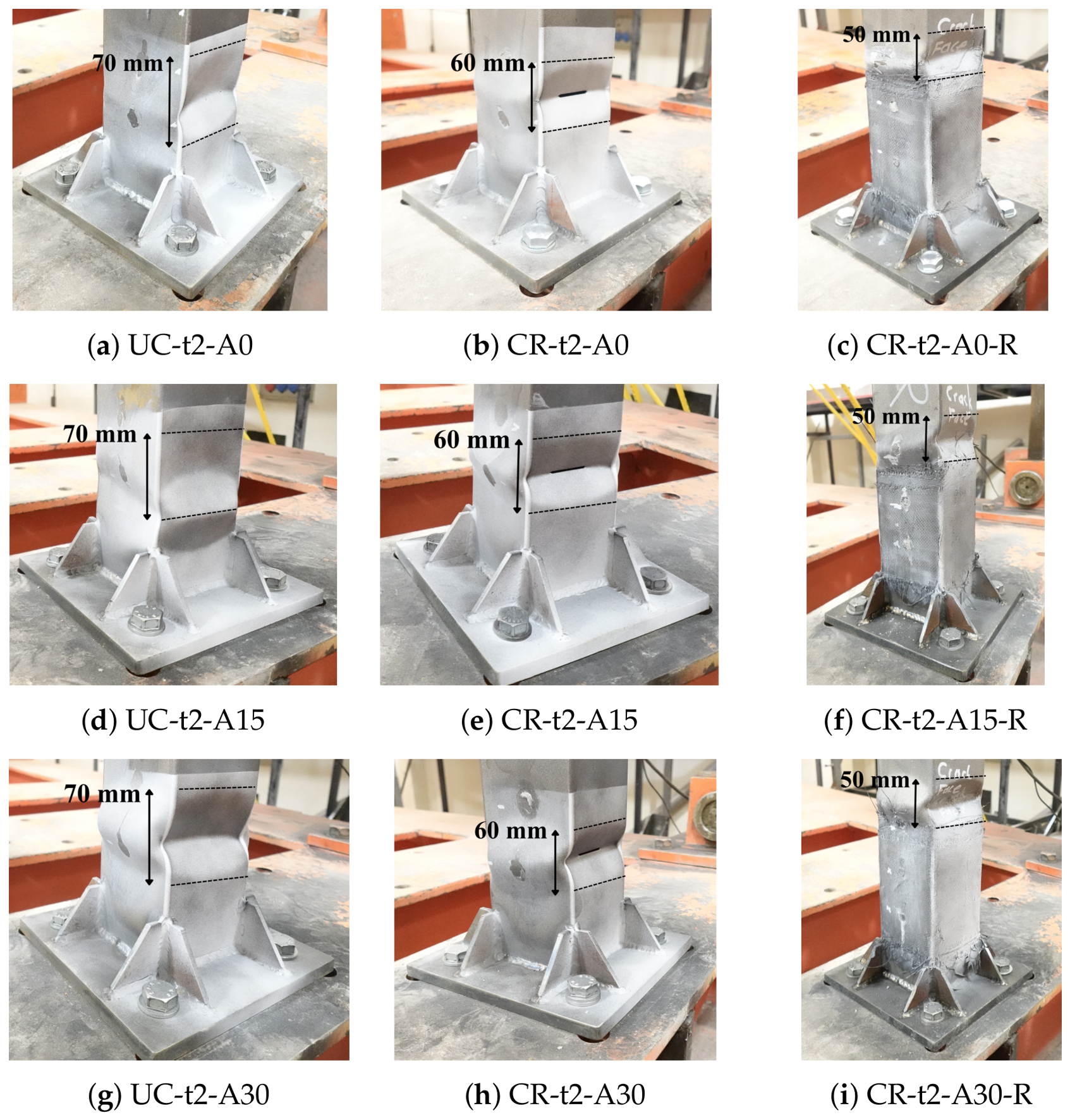
To clarify the damage progression of the tested steel SHS column specimens, the failure modes were examined with respect to initial crack defects, section slenderness, and nominal axial load ratio. In this evaluation, section slenderness was considered the main variable, together with nominal axial load ratios of 0, , and . Moreover, local strengthening with CFRP wrapping was applied to the cracked steel SHS specimens, and its effect on the observed failure modes was evaluated in the same manner. The main damage mechanisms were local buckling, crack propagation, CFRP rupture, debonding between the CFRP and steel surface, and combinations of these mechanisms. The final failure states of the mm specimens and the observed local buckling half-wave lengths are shown in Figure 11. The indicated dimensions represent the approximate local buckling half-wave lengths of the specimens.
Figure 11.
Final failure states of the mm specimens with indicated local buckling half-wave lengths.
As shown in Figure 11, the failure of the mm specimens was governed by local buckling. For the uncracked specimens, the center of the local buckling wave was located approximately 5.5 cm above the stiffeners. However, in the cracked specimens, the center of the buckling wave slightly shifted upward and was located approximately 6.5 cm above the stiffeners, within the crack region. For the mm specimens, the severity of local buckling increased with increasing nominal axial load ratio. However, the overall failure mode did not change. All specimens failed due to local buckling, and crack propagation was not observed.
A clear difference was observed between cracked specimens and cracked specimens retrofitted with local CFRP wrapping. No visible damage was observed within the CFRP-wrapped region for any of the CFRP-wrapped specimens, regardless of the nominal axial load ratio. In addition, no rupture of the CFRP fabric and no debonding between the CFRP fabric and the steel surface were observed. In all CFRP-wrapped specimens, local buckling developed at the termination of the CFRP wrapping. The CFRP wrapping clearly shifted the location of the local buckling wave and prevented visible damage within the locally wrapped region. Therefore, local CFRP wrapping was considered effective in preventing damage in the retrofitted area for the mm specimens.
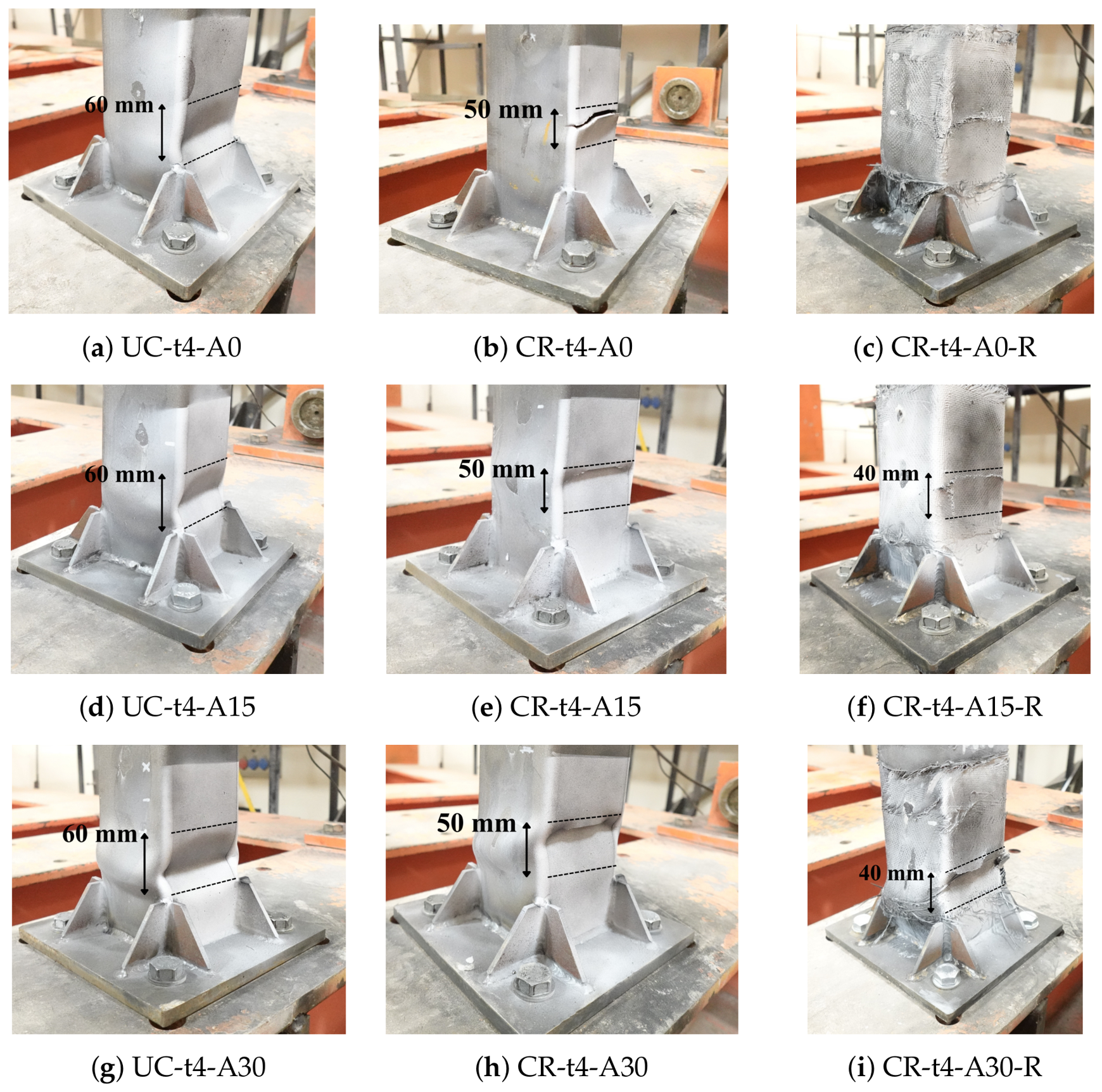
The final failure states of the mm specimens and the observed local buckling half-wave lengths are shown in Figure 12. The indicated dimensions represent the approximate local buckling half-wave lengths of the specimens. For the CR-t4-A0-R specimen, a distinct local buckling half-wave could not be clearly observed. Therefore, a corresponding half-wave length was not indicated in Figure 12.
Figure 12.
Final failure states of the mm specimens with indicated local buckling half-wave lengths.
As shown in Figure 12, the failure mechanisms of the mm specimens were different from those of the mm specimens. The mm specimens exhibited different failure responses depending on the presence of an initial crack defect. The uncracked specimens failed by local buckling, whereas the cracked specimens exhibited fracture-dominated behavior under zero axial load and combined fracture-local buckling under axial loading. The local buckling behavior of the uncracked specimens was similar to that of the mm specimens. In contrast, the center of the local buckling wave was located approximately cm above the stiffeners. However, in the cracked specimens, the center of the buckling wave slightly shifted upward and was located approximately 6.5 cm above the stiffeners, within the crack region.
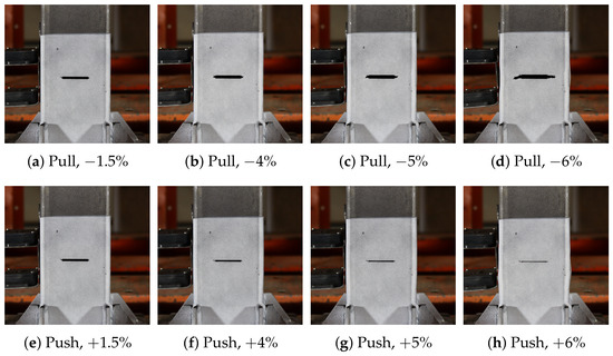
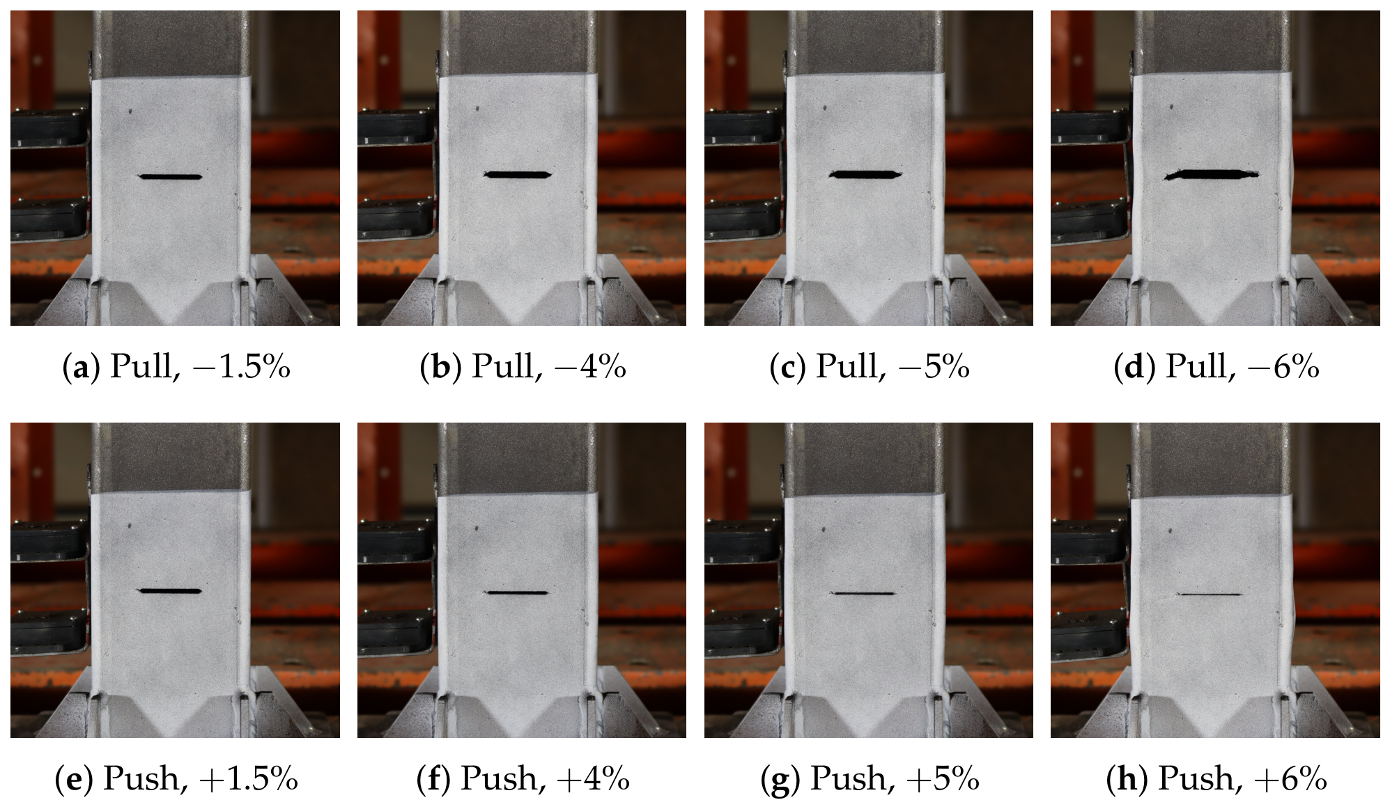
For the cracked specimens, the presence of the initial crack strongly affected the failure mechanism. In the specimen tested without axial load, failure was mainly governed by crack opening and crack propagation, while the effect of local buckling was not notable. At the drift ratio, the crack faces visibly opened and closed during the pull and push cycles. Starting from the drift ratio, visible crack propagation was observed. During the pull cycles, the crack progressively propagated, whereas during the push cycles, the crack closed and the crack faces came into contact. Eventually, the crack propagated across the loaded face and extended toward the side face, resulting in a fracture-dominated failure mechanism.
In the specimen tested under a nominal axial load ratio of , visible crack propagation started at the drift ratio. As the test progressed, the crack propagation mechanism became associated with local buckling. As the crack propagated, the effective load-carrying area around the crack region decreased. Under the combined effect of axial load and cyclic lateral loading, local buckling started to develop, although it was not severe. Therefore, the failure mechanism was governed by the interaction between crack propagation/fracture and local buckling.
Similarly, for the specimen tested under a nominal axial load ratio of , visible crack propagation started at the drift ratio. However, the higher axial load also increased the tendency for local buckling after crack propagation. In this specimen, severe local buckling developed due to the combined effects of axial load and cyclic lateral loading. Therefore, the specimen failed through a combined mechanism of fracture and local buckling, with local buckling becoming the dominant failure mode.
For the CFRP-wrapped cracked specimens, failure was noted again around the crack region; however, CFRP wrapping notably reduced local deformation around the initially cracked region and delayed the development of severe local buckling. Under the zero axial load condition, rupture of the CFRP fabric was observed at the crack location, while no visible debonding was observed between the CFRP fabric and the steel surface. Under the nominal axial load ratio of , CFRP rupture was again observed at the crack location, and local buckling was notably reduced compared with the corresponding unwrapped cracked specimen. No visible debonding was observed between the CFRP fabric and the steel surface. Under the nominal axial load ratio of , more pronounced CFRP rupture occurred around the crack region. Although local buckling was not as severe as that observed in the corresponding unwrapped cracked specimen, considerable local deformation still developed. In addition, visible debonding between the CFRP fabric and the steel surface was observed due to an increase in axial load ratio.
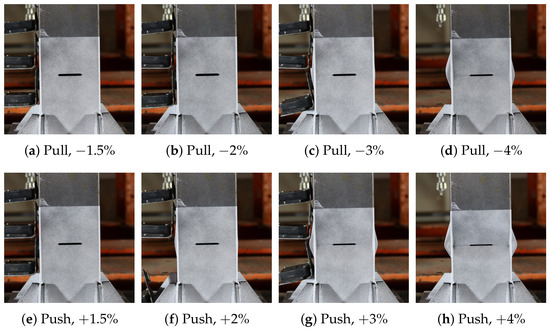
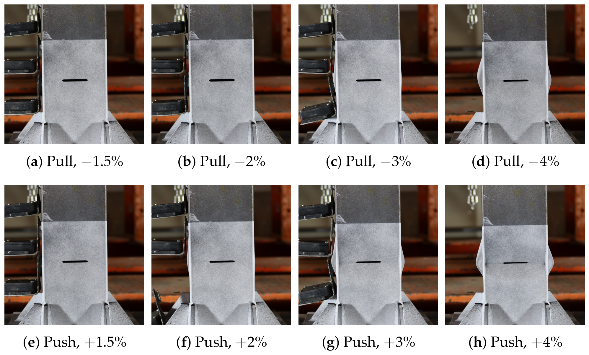
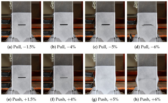
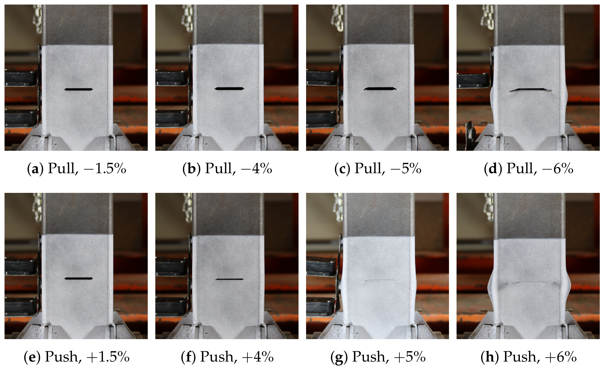
To further illustrate the observed damage states, progressive damage development is presented for selected representative steel SHS specimens in Figure 13, Figure 14 and Figure 15. The specimens CR-t2-A15, CR-t4-A0, and CR-t4-A15 were selected to represent local buckling-dominated failure, fracture-dominated failure, and combined local buckling–fracture failure, respectively.
Figure 13.
The failure progression of CR-t2-A15 at selected drift ratios.
Figure 14.
The failure progression of CR-t4-A0 at selected drift ratios.
Figure 15.
The failure progression of CR-t4-A15 at selected drift ratios.
3.2. Hysteresis Response and Cyclic Performance Parameters
The lateral cyclic performance of the tested steel SHS specimens was evaluated and discussed based on hysteresis responses, backbone curves, and performance parameters calculated in accordance with ASTM E2126 [47]. The backbone curves were obtained from the peak responses of the hysteresis curves and were used to compute the main cyclic performance parameters. In this section, the results are discussed in terms of overall hysteretic behavior and cyclic performance with respect to the effects of section slenderness, nominal axial load ratio, initial crack defects, and CFRP wrapping.
In general, the mm specimens initially exhibited stable behavior at low drift levels. After damage initiation, an abrupt reduction in lateral load capacity was observed. The visible damage accumulation in the mm specimens became more pronounced at around the drift ratio. The nominal axial load ratio, the presence of an initial crack, and CFRP wrapping influenced the peak lateral load, yield point, backbone energy, and ductility. These performance parameters, which are summarized in Table 9, should be interpreted together. Considering the parameters individually may lead to an incomplete or incorrect interpretation of the specimens’ lateral cyclic performance. For this reason, the cyclic performance parameters were interpreted together and consistently in this section.
Table 9.
Cyclic performance parameters of the mm specimens.
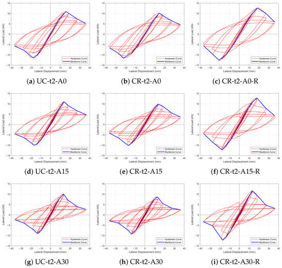
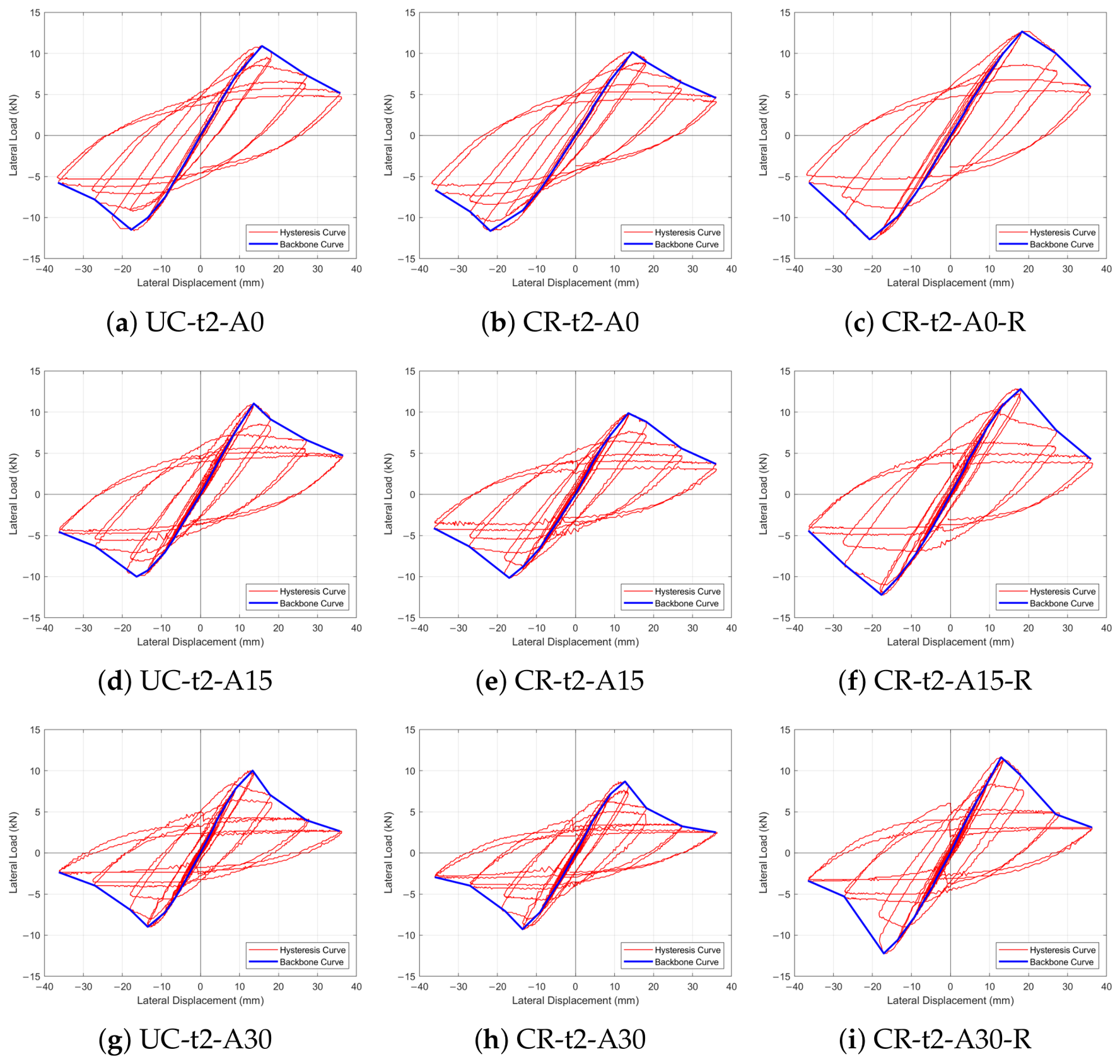
The hysteresis and backbone curves of the t=2 mm specimens are shown in Figure 16, and the corresponding cyclic performance parameters are presented in Table 9.
Figure 16.
Hysteresis and backbone curves of the mm specimens.
For the mm specimens tested under zero axial load, the presence of the initial crack did not cause a severe reduction in lateral load capacity or yield load. Based on the average values calculated from the absolute magnitudes of the push and pull results, the lateral load capacity and yield load were reduced by and , respectively. The backbone energy and ductility remained approximately unchanged. This situation can be explained by the fact that, without axial loading, the destabilizing effect of the initial crack defect was limited. The CFRP-wrapped cracked specimen exhibited increases of and in lateral load capacity and yield load, respectively, compared with the uncracked specimen. Although the ductility ratio remained approximately the same, the backbone energy increased by . In terms of effective stiffness, the initial crack defect caused a decrease compared with the uncracked specimen. CFRP wrapping had a positive effect on the recovery of effective stiffness for the cracked specimens. For the CFRP-wrapped cracked specimen, the effective stiffness was only lower than that of the uncracked specimen, indicating that CFRP wrapping partially recovered the stiffness loss caused by the initial crack defect.
For the mm specimens tested at a nominal axial load ratio of , the comparison of the uncracked specimen with the cracked specimen for the cyclic performance parameters showed reductions in lateral load capacity and yield load by and , respectively. While the backbone energy remained nearly unchanged, the effective stiffness decreased by . Although the ductility ratio increased by , interpreting this parameter alone would be misleading, since decreases were observed in the lateral load capacity, yield load, and effective stiffness of the cracked specimen. The most likely reason for this increase in ductility is the occurrence of local buckling in the crack region and the earlier yielding triggered by stress concentrations around the crack tips, which increased the deformation of the cracked specimen after yielding despite its reduced lateral loading capacity. The CFRP-wrapped cracked specimen showed a increase in effective stiffness compared with the uncracked specimen. In addition, the lateral load capacity and yield load increased by and , respectively, while the backbone energy increased by .
For the mm specimens tested at a nominal axial load ratio of , compared with the uncracked specimen, the cracked specimen showed reductions in lateral load capacity by , yield load by , effective stiffness by , and backbone energy by . Compared with the uncracked specimen, the CFRP-wrapped cracked specimen exhibited increases in lateral load capacity by , yield load by , and backbone energy by . In terms of effective stiffness, CFRP wrapping recovered the stiffness loss caused by the crack defect and slightly increased the effective stiffness by compared with the uncracked specimen.
Based on the cyclic performance parameters of the mm specimens, the negative effects of the initial crack defect became more pronounced in the presence of axial loading. These effects further increased as the nominal axial load ratio increased. This behavior is explained by the combined loading condition, which increased second-order effects. Another reason is that stress concentration around the crack tips and the reduction in the effective axial load-carrying cross-sectional area under combined axial and lateral loading made the cracked specimens more susceptible to local buckling. In addition, the effectiveness of CFRP wrapping in the cracked specimens became more evident in the presence of axial loading and further increased with the increasing nominal axial load ratio. This improvement can be explained by the suppression of visible local deformation in the CFRP-wrapped region. As a result, local buckling was not observed within the wrapped region and was shifted upward to the end of the CFRP-wrapped region.
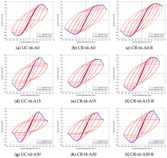
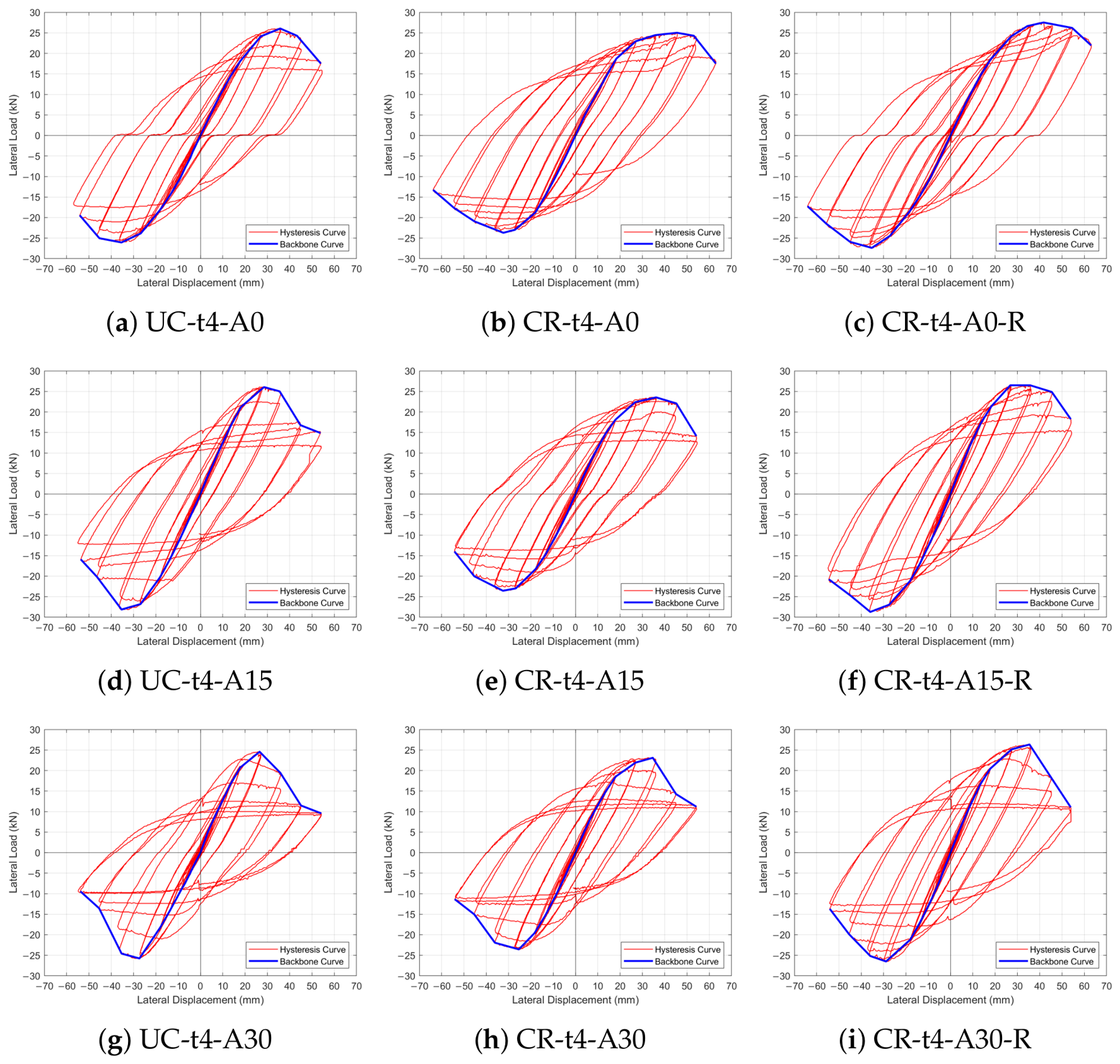
The lateral cyclic performance evaluation is extended to the mm non-slender specimens, which exhibited a higher lateral load capacity and more stable post-yield behavior. Damage development became noticeable around the drift ratio. Figure 17 presents the corresponding hysteresis and backbone curves, while Table 10 summarizes the cyclic performance parameters.
Figure 17.
Hysteresis and backbone curves of the mm specimens.
Table 10.
Cyclic performance parameters of the mm specimens.
For the mm specimens tested under zero axial load, based on the average values calculated from the absolute magnitudes of the push and pull results, the cracked specimen showed reductions of , , and in lateral load capacity, yield load, and effective stiffness, respectively, compared with the uncracked specimen. However, the direct comparison of backbone energy and ductility may lead to a misleading interpretation, since the specimens did not reach the same maximum drift ratio under zero axial loading. Therefore, energy dissipation is further evaluated in the cumulative energy dissipation section by comparing the specimens at the same drift ratio level. CFRP wrapping mostly recovered the decrease in effective stiffness caused by the initial crack defect, and the reduction in effective stiffness was reduced to . In addition, the CFRP-wrapped cracked specimen showed increases of and in lateral load capacity and yield load, respectively, compared with the uncracked specimen.
For the mm specimens tested at a nominal axial load ratio of , compared with the uncracked specimen, the cracked specimen showed reductions of , , and in lateral load capacity, yield load, and effective stiffness, respectively. Despite the reductions in strength-related parameters, the backbone energy and ductility ratio were relatively higher in the cracked specimen. This situation was associated with crack-induced earlier yielding and larger post-yield deformation caused by localized damage around the crack tips and crack propagation. The effect of CFRP wrapping became more pronounced at the nominal axial load ratio. Compared with the uncracked specimen, the CFRP-wrapped cracked specimen exhibited increases of , , , , and in lateral load capacity, yield load, effective stiffness, ductility, and backbone energy, respectively. This indicates that CFRP wrapping not only recovered the stiffness loss caused by the crack defect but also improved the strength and energy dissipation capacity under combined axial and lateral loading.
For the mm specimens tested at a nominal axial load ratio of , compared with the uncracked specimen, the cracked specimen showed reductions of and in lateral load capacity and yield load, respectively. However, the effective stiffness remained approximately unchanged. This behavior can be attributed to the delayed crack opening caused by the compressive effect of the axial load. Compared with the uncracked specimen, the CFRP-wrapped cracked specimen exhibited increases of , , and in lateral load capacity, yield load, and effective stiffness, respectively. In addition, ductility and backbone energy increased by and , respectively.
The cyclic performance parameters of the mm specimens indicated a notable adverse effect of the initial crack defect; however, this effect did not exhibit a clear monotonic trend with increasing nominal axial load ratio. The reductions in strength-related parameters became more evident in the presence of axial loading. However, the maximum reduction in lateral load capacity occurred at the nominal axial load ratio. This behavior can be explained by the observed failure modes of the cracked specimens. Under zero axial load, the cracked specimen mainly failed by crack propagation. At the nominal axial load ratio, the failure mechanism was governed by combined crack propagation and local buckling, whereas at the nominal axial load ratio, crack propagation was accompanied by more dominant local buckling. The effectiveness of CFRP wrapping in improving strength-related parameters was most notable under zero axial load, followed by the and nominal axial load ratios. In terms of effective stiffness, CFRP wrapping provided an improvement, and this improvement became more pronounced as the nominal axial load ratio increased. This behavior can also be associated with the observed failure modes. CFRP wrapping did not completely suppress local buckling within the wrapped region; however, it limited local buckling and reduced the severity of local deformation.
In both thickness groups, differences were observed between the performance parameters obtained in the push and pull directions, especially for the cracked test specimens. This behavior can be mainly attributed to different crack responses between the push and pull directions. In the pull direction, the crack tends to open, whereas in the push direction, the crack tends to close. This behavior was more pronounced in the mm cracked specimens since crack opening and crack contact were observed at all nominal axial load ratios. Therefore, crack opening and crack contact mechanisms have an influence on the differences in performance parameters between the push and pull directions.
For both mm and mm specimens, the results indicate that there is no linear relationship between energy and ductility ratio for uncracked, cracked, and CFRP-wrapped cracked specimens at all nominal axial load ratios. This situation can be attributed to energy and ductility being affected by different parameters. The ductility ratio was calculated based on deformation capacity as the ratio of ultimate displacement () to yield displacement (); however, energy was affected by both displacement capacity and peak lateral load () and was calculated by using the area under the backbone curve. Therefore, there was no linear relationship between ductility ratio and energy.
3.3. Performance Limit-State Evaluation
To make a correlation between applied drift ratios and seismic performance levels, the drift responses and the corresponding damage states of the tested steel SHS column specimens were evaluated with reference to FEMA 356 performance levels [48]. These performance levels are Immediate Occupancy (IO), Life Safety (LS), and Collapse Prevention (CP). FEMA 356 provides reference drift ratios for steel frames corresponding to these performance levels. The reference transient drift ratios were derived from the performance levels of steel moment frames outlined in FEMA 356. These drift limits are defined at the structural-system level; therefore, these performance levels were used only as references rather than direct criteria. FEMA 356 drift ratio limits and the corresponding performance levels and damage states are shown in Table 11.
Table 11.
FEMA 356 drift ratio limits and corresponding performance levels and damage states [48].
The mm specimens generally exhibited stable behavior at low drift ratios up to the drift ratio. Visible damage accumulation and a meaningful reduction in lateral load capacity became more pronounced at approximately the drift ratio, which lies between the IO and LS performance levels. After this point, local buckling became more pronounced, and an abrupt reduction in lateral load capacity was observed. In the CFRP-wrapped mm specimens, lateral load capacity was increased, and no visible damage was observed within the wrapped region; instead, local buckling shifted upward to the end of the CFRP-wrapped region.
The mm specimens exhibited more stable behavior with increasing drift ratios, and there was no abrupt reduction in lateral load capacity unlike the mm specimens. Damage accumulation became noticeable at approximately the drift ratio, while visible crack propagation in the cracked specimens started at approximately the drift ratio, which is above the LS performance level and between the LS and CP performance levels. CFRP wrapping reduced the severity of local damage in the mm specimens. For the CFRP-wrapped specimens tested at nominal axial load ratios of 0 and , the lateral load remained at approximately of the peak load beyond the CP drift level. At the drift ratio, the lateral load capacity of the CFRP-wrapped cracked specimen under zero nominal axial load ratio decreased to approximately of its peak value.
3.4. Cumulative Energy Dissipation
Cumulative energy dissipation is an important indicator for evaluating the lateral cyclic performance of structural members. Therefore, the cumulative energy dissipation responses of the uncracked, cracked, and CFRP-wrapped cracked specimens were evaluated and compared considering different section thicknesses and nominal axial load ratios. To make a fair comparison, cumulative energy dissipation values were compared over the same completed loading history within each wall-thickness group. The common drift ratios were for the mm specimens and for the mm specimens.
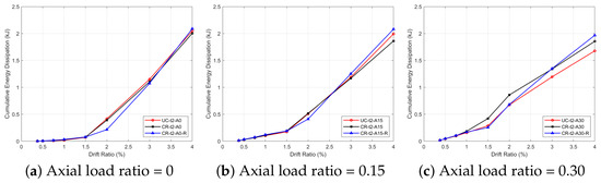
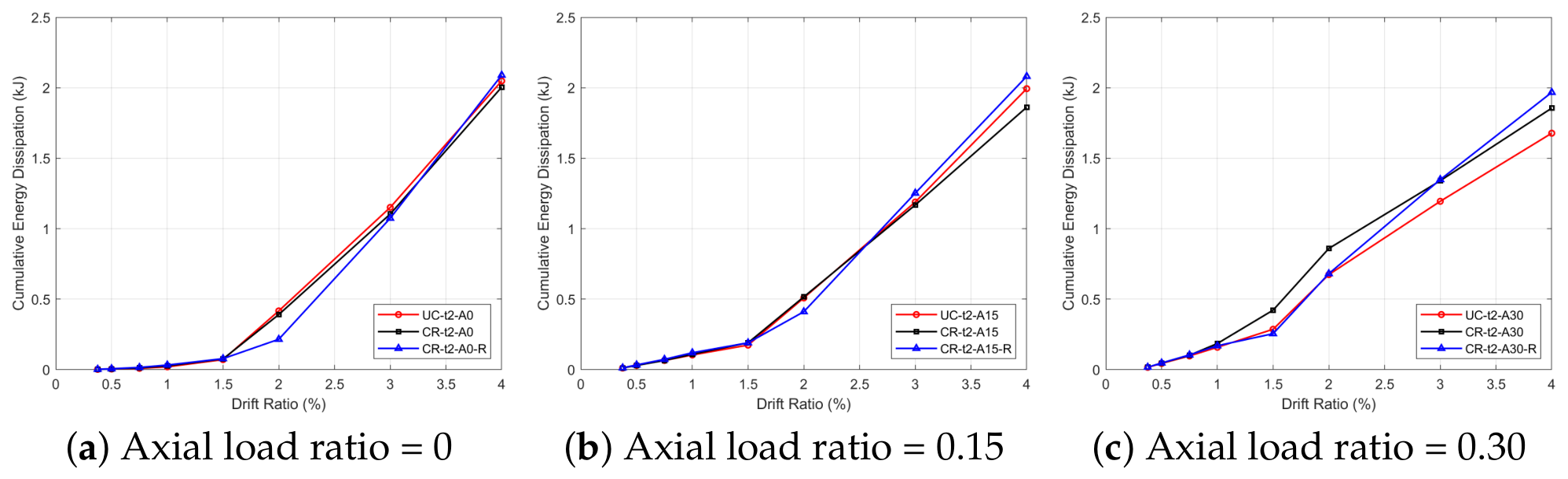
The cumulative energy dissipation curves of the mm specimens under different nominal axial load ratios are presented in Figure 18.
Figure 18.
Cumulative energy dissipation responses of the mm specimens under different nominal axial load ratios.
For the mm specimens, CFRP wrapping increased the cumulative energy dissipation capacity of the cracked specimens compared with both the uncracked and cracked specimens under all nominal axial load ratios. Under zero axial load, the CFRP-wrapped cracked specimen exhibited increases in cumulative energy dissipation of and compared with the uncracked and cracked specimens, respectively. At the nominal axial load ratio, the corresponding increases were and , respectively. At the nominal axial load ratio, the CFRP-wrapped cracked specimen showed increases of and compared with the uncracked and cracked specimens, respectively. Despite the loss of strength, the cracked specimen dissipated more cumulative energy than the uncracked specimen at the nominal axial load ratio. This behavior was mainly attributed to the lower yield load of the cracked specimen, which led to earlier yielding and larger post-yield deformation. Moreover, the effectiveness of CFRP wrapping increased with increasing nominal axial load ratio. This can be attributed to the increased severity of local buckling under higher axial load ratios, while CFRP wrapping suppressed visible local deformation within the wrapped region and shifted local buckling upward from the CFRP-wrapped region. Therefore, the contribution of CFRP wrapping became more pronounced as the nominal axial load ratio increased.
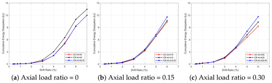
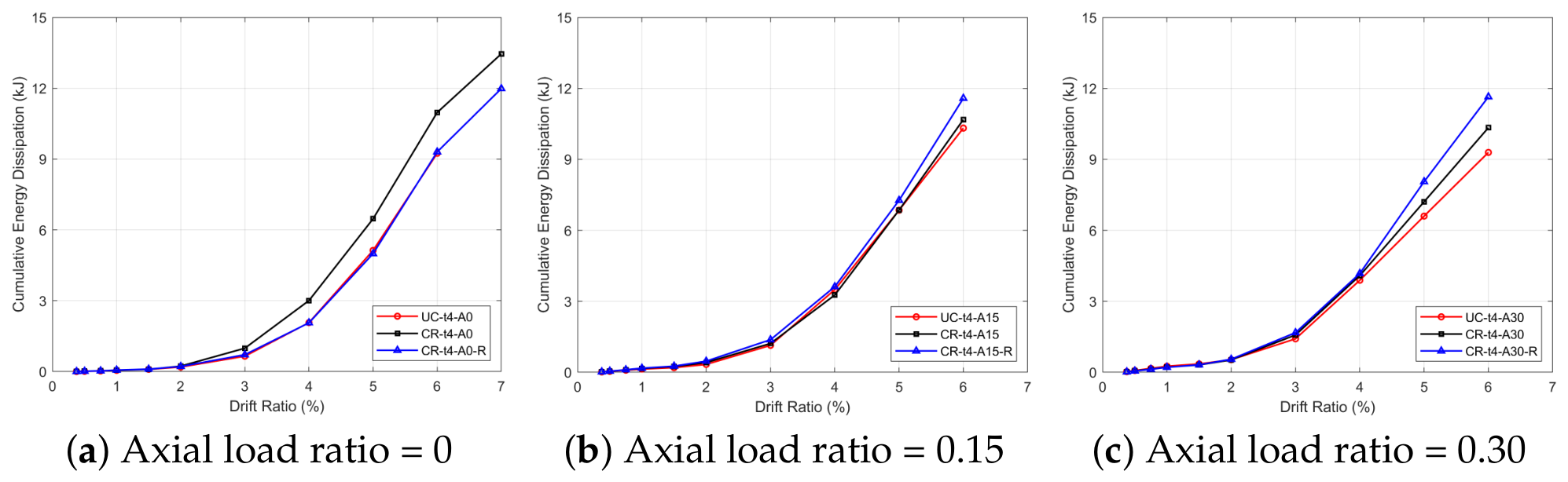
The evaluation of cumulative energy dissipation was then extended to the mm specimens, and the corresponding cumulative energy dissipation curves are shown in Figure 19.
Figure 19.
Cumulative energy dissipation responses of the mm specimens under different nominal axial load ratios.
For the mm specimens, the cumulative energy dissipation values under zero axial load were compared at a common drift ratio of to provide a fair comparison. CFRP wrapping caused a negligible increase of in cumulative energy dissipation compared with the uncracked specimen. However, the cracked specimen also exhibited slightly higher cumulative energy dissipation than the uncracked specimen, despite its reduced strength-related parameters. For all mm cracked specimens, the initial crack caused reductions in strength-related parameters, although slightly higher cumulative energy dissipation. This behavior can be attributed to the lower yield capacity caused by the crack defect, which lowered the yield load and caused larger post-yield deformation. In addition, crack propagation was observed in all mm cracked specimens. Crack propagation may have contributed to the increased energy dissipation. At the nominal axial load ratio, the CFRP-wrapped cracked specimen showed increases of and in cumulative energy dissipation compared with the uncracked and cracked specimens, respectively. At the nominal axial load ratio, the corresponding increases were and , respectively. Cumulative energy dissipation results showed that CFRP wrapping provided a notable increase in the cumulative energy dissipation capacity of the specimens tested under axial loading. For the mm specimens, damage was still observed in the crack region of the CFRP-wrapped specimens. However, CFRP wrapping notably reduced the severity of local buckling and provided a confinement-like effect. This behavior may explain why CFRP wrapping was more effective under axial loading for the mm specimens.
3.5. Stiffness Degradation
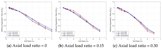
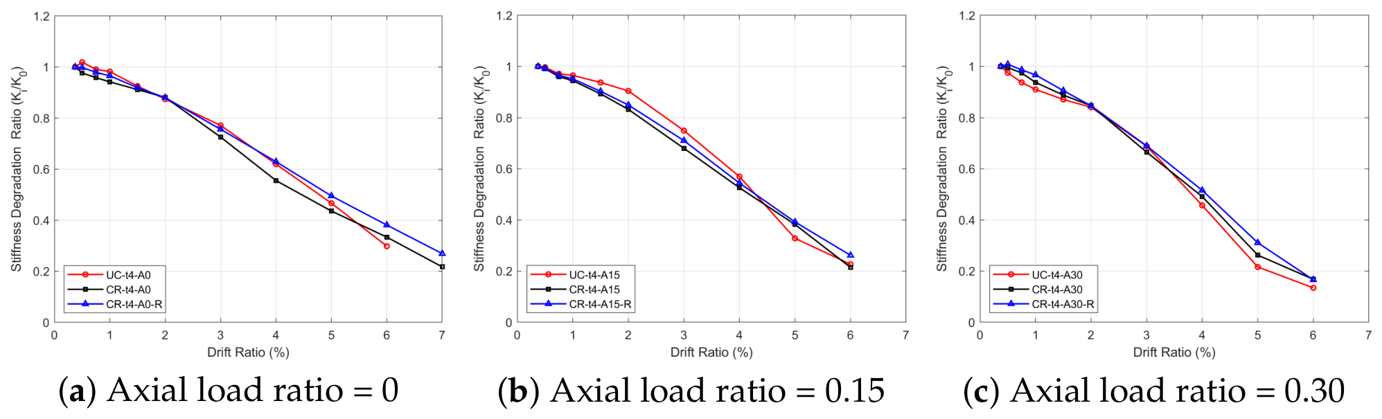
Stiffness degradation ratio (SDR) curves provide important information about damage accumulation as the drift ratio increases. Therefore, SDR curves are useful indicators for evaluating stiffness degradation and damage progression under cyclic loading. For each wall-thickness group, the comparison drift ratio was selected as the level at which clear differences among the SDR values of the uncracked, cracked, and CFRP-wrapped cracked specimens became apparent. Accordingly, the SDR values were compared at the drift ratio for the mm specimens and at the drift ratio for the mm specimens.
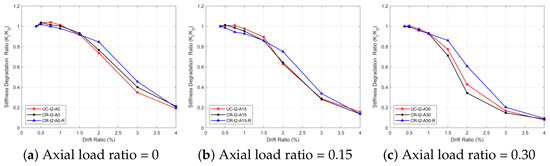
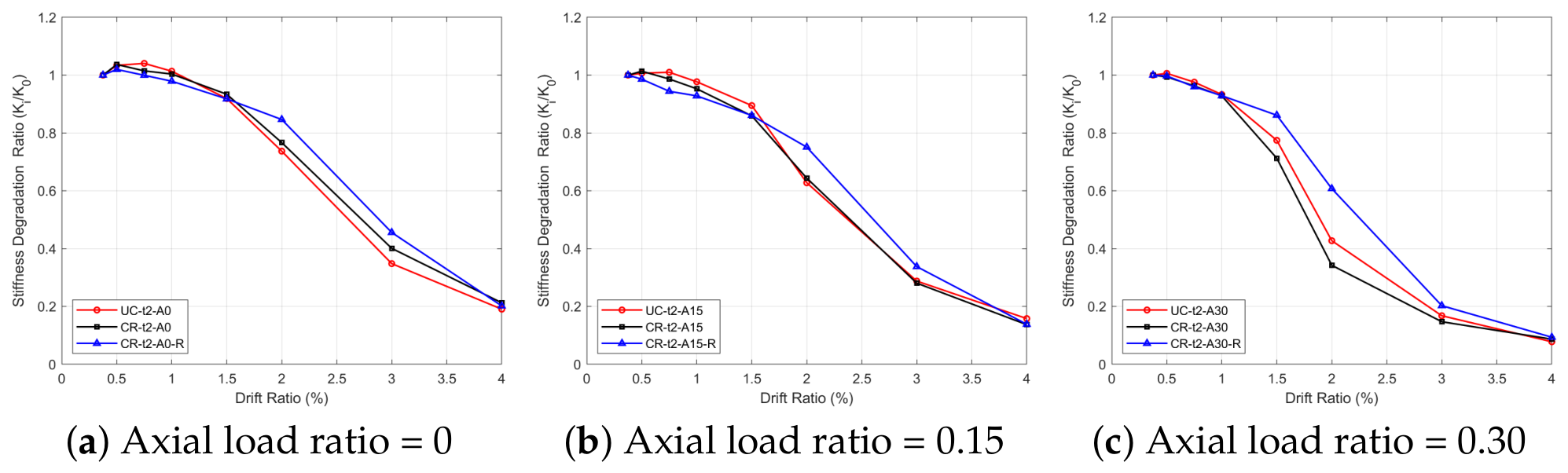
The SDR curves of the mm specimens are presented in Figure 20.
Figure 20.
SDR curves of the mm specimens under different nominal axial load ratios.
For the mm specimens, under zero axial load, an evident reduction in stiffness started at a drift ratio. Therefore, the SDR values were compared at the drift ratio. The SDR values of the uncracked, cracked, and CFRP-wrapped cracked specimens were , , and , respectively. At the nominal axial load ratio, the SDR values of the uncracked, cracked, and CFRP-wrapped cracked specimens were , , and , respectively. No notable difference was observed between the SDR values of the uncracked and cracked specimens under zero axial load and at the nominal axial load ratio. However, CFRP wrapping reduced the stiffness degradation compared with uncracked and cracked specimens. At the nominal axial load ratio, the effect of the initial crack defect and CFRP wrapping became more pronounced. The SDR values of the uncracked, cracked, and CFRP-wrapped cracked specimens were , , and , respectively. The SDR curves showed that the negative effect of the initial crack defect became more pronounced with increasing nominal axial load ratio. In addition, CFRP wrapping reduced stiffness degradation in all cases, and its effectiveness became more evident as the nominal axial load ratio increased.
The evaluation of stiffness degradation ratio was then extended to the mm specimens, and the corresponding SDR curves are shown in Figure 21.
Figure 21.
SDR curves of the mm specimens under different nominal axial load ratios.
For the mm specimens, notable stiffness degradation started after the drift ratio; however, the difference in SDR values became more evident at the drift ratio. For this reason, the SDR values of the uncracked, cracked, and CFRP-wrapped specimens were compared at the drift ratio. Under zero axial load, the SDR values of the uncracked, cracked, and CFRP-wrapped specimens were , , and , respectively. At the nominal axial load ratio, the SDR values were , , and , respectively. At the nominal axial load ratio, the corresponding SDR values were , , and , respectively. The presence of the initial crack defect increased stiffness degradation under all nominal axial load ratios. Under zero axial load, CFRP wrapping almost completely recovered the stiffness loss caused by the initial crack defect. At the nominal axial load ratio, CFRP wrapping provided partial recovery of the stiffness loss. At the nominal axial load ratio, CFRP wrapping completely recovered the stiffness loss, and the SDR value reached the level of the uncracked specimen.
3.6. 2D DIC Analysis Results
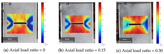
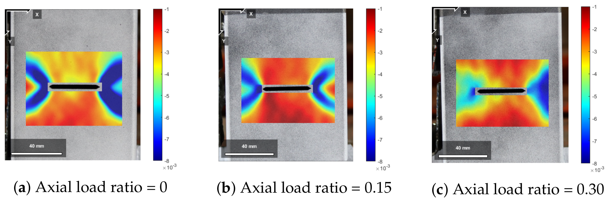
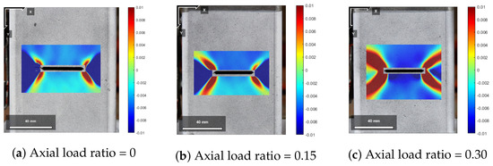
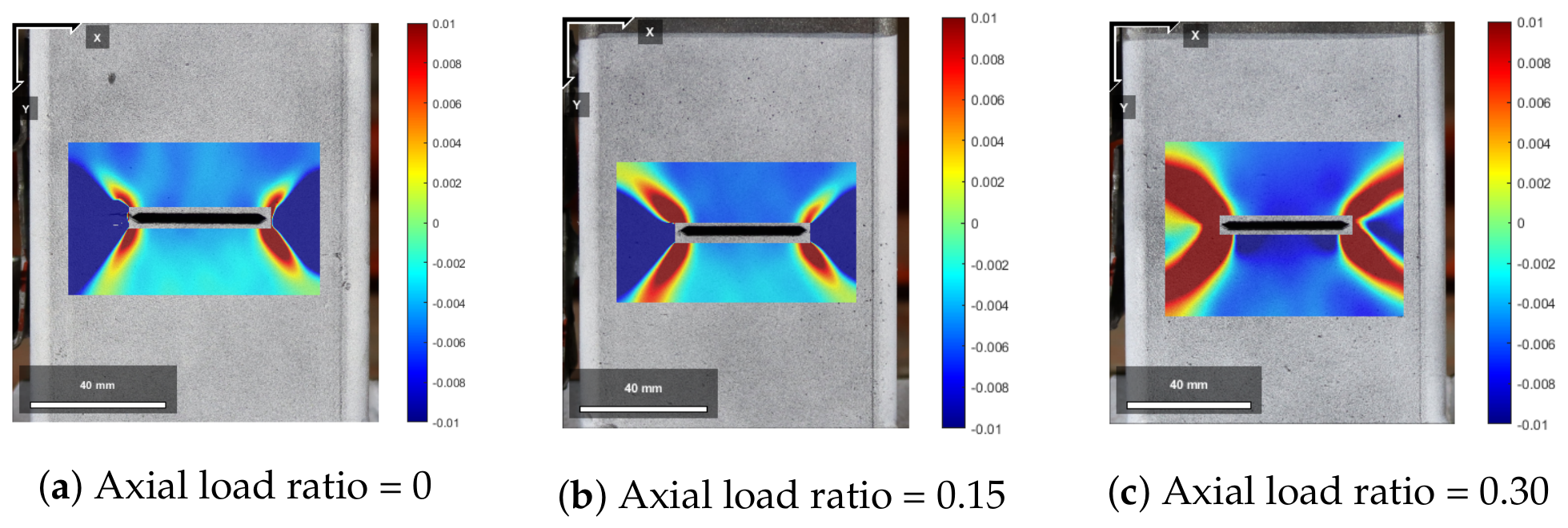
2D-DIC analysis was performed to evaluate the strain localization pattern around the crack tips and the crack region. The Green–Lagrangian strain fields obtained in the crack opening direction are presented in Figure 22 for the mm specimens at the drift ratio and in Figure 23 for the mm specimens at the drift ratio.
Figure 22.
Green–Lagrangian strain fields of the mm cracked specimens in the crack opening direction at the drift ratio.
Figure 23.
Green–Lagrangian strain fields of the mm cracked specimens in the crack opening direction at the drift ratio.
2D-DIC results show that for mm specimens, strain concentration increased at the crack tips, and the strain concentration region enlarged with increasing nominal axial load ratio. Generally, bean-shaped strain concentrations were observed at the crack tips, which is the classical crack tip strain pattern for the plane-stress conditions. However, at the nominal axial load ratio, this bean-shaped crack tip strain became a more irregular pattern and extended over a wider region. This situation can be associated with severe local buckling with increased axial load at the crack region. Therefore, although an increase in axial load led to higher strain concentration at the crack tips, the severe local buckling observed in the mm specimen at the nominal axial load ratio caused the strain concentration pattern to become more irregular and to extend over a wider area around the crack region.
For mm specimens, typical bean-shaped plane-stress–strain concentrations at the crack tips were similar to those of mm specimens; however, sharper bean-shaped strain concentrations occurred at the crack tips when compared with mm specimens. At all nominal axial load ratios, sharper bean-shaped strain concentrations occurred at the crack tips in mm specimens, unlike mm specimens. This situation can be attributed to the occurrence of crack propagation at all nominal axial load ratios. Even though the combined crack propagation-buckling mechanism was observed, crack propagation had an important influence on the failure mechanism. The strain concentration around the crack tips became more intense with increasing axial load, and the bean-shaped high-strain regions extended over a larger area.
3.7. Comparison with Previous Studies
In this section, the findings of the current study are compared with similar studies available in the literature. Kumar and Senthil reported that CFRP strengthening increased load capacity under static axial and cyclic axial loading by and [26]. However, their study did not consider initial defects such as cracks or notches. Ghaemdoust et al. reported that initial notch defects in steel SHS short columns caused a reduction in axial load-carrying capacity, and CFRP wrapping increased axial load-carrying capacity by under compression only [24]. Gao et al. reported that retrofitting corroded steel tubes using CFRP wrapping increased the bending capacity by [20]. In the current study, initial crack defects reduced the lateral load capacity by up to and for the mm and mm specimens, respectively, compared with the corresponding uncracked specimens. The CFRP-wrapped cracked specimens exhibited lateral load capacities up to and higher than the corresponding uncracked specimens for the mm and mm groups, respectively. However, the previous studies did not consider the effect of combined loading. Therefore, direct comparison of the results should be made carefully due to the different loading conditions, materials, specimens, and defect geometries. Nevertheless, the current study obtained similar outcomes in terms of the adverse effects of initial defects on the performance of the member and the effectiveness of CFRP. The current study investigated the adverse effects of initial crack defects in steel SHS columns under lateral cyclic loading combined with three different nominal axial load ratios for slender and non-slender cross sections. Therefore, the slenderness effect and the effect of different nominal axial load ratios were considered. In addition to that, the current study suggests a local strengthening via CFRP wrapping for these structural members. Thus, the current study investigated a more complex combined loading condition for slender and non-slender cross-sections. This study shows that adverse effects of the initial cracks can be mitigated via local CFRP wrapping. From a practical perspective, local CFRP wrapping can be considered an effective strengthening method for cracked steel SHS columns.
4. Conclusions
In the scope of this experimental research, the lateral cyclic behavior of slender and non-slender steel SHS columns with initial crack defects under different nominal axial load ratios was investigated. To simulate an initial crack defect, a horizontal notch was introduced in the plastic hinge region of the columns, and lateral cyclic loading was applied in the crack opening and closing directions; thus, one of the critical conditions was simulated. In addition, this research offered a local retrofit strategy using CFRP wrapping in the crack region. The effects of wall thickness, initial crack defect, different nominal axial load ratios, and local CFRP wrapping were evaluated using failure modes, hysteretic behavior, cyclic performance parameters, cumulative energy dissipation, and stiffness degradation ratio. In addition, 2D-DIC analysis was performed to obtain strain fields in the crack region of the cracked specimens. Based on the experimental results, the following conclusions can be drawn:
- 1.
- The nominal axial load ratio and the wall thickness of the tested steel SHS columns strongly influenced the failure modes. For the cracked mm specimens, failure was always governed by local buckling. For the mm specimens, fracture/crack propagation occurred in all nominal axial load ratios; however, local buckling became more pronounced as the nominal axial load ratio increased.
- 2.
- For both thickness groups, initial crack defects adversely affected strength-related parameters such as lateral load capacity and yield load. For the mm specimens, the maximum reduction in strength-related parameters occurred at the nominal axial load ratio, where lateral load capacity and yield load decreased by and , respectively. For the mm specimens, the maximum reductions occurred at the nominal axial load ratio, where lateral load capacity and yield load decreased by and , respectively.
- 3.
- CFRP wrapping improved strength-related parameters. CFRP wrapping increased the lateral load capacity and yield load by up to and for the mm specimens and by up to and for the mm cracked specimens compared with the corresponding uncracked specimens.
- 4.
- CFRP wrapping increased cumulative energy dissipation capacities of the cracked specimens compared with uncracked specimens for both thickness groups. For the mm specimens, increases in energy dissipation capacities were , , and under 0, , and nominal axial load ratios, respectively. For the mm specimens, the corresponding increases were , , and .
- 5.
- CFRP wrapping improved the lateral cyclic performance of the cracked specimens. For the mm specimens, no visible damage was observed within the wrapping region, and local buckling shifted toward the end of the wrapped region. For the mm specimens, CFRP wrapping limited local buckling; however, CFRP rupture was observed around the crack region. Visible CFRP-steel debonding was observed only in the mm specimen under the nominal axial load ratio.
- 6.
- The SDR curves indicated that the initial crack defect increased stiffness degradation; however, CFRP wrapping reduced stiffness degradation, and the effectiveness of CFRP wrapping became more pronounced at the nominal axial load ratio. At the nominal axial load ratio, the SDR values of the uncracked, cracked, and CFRP-wrapped cracked mm specimens were , , and , respectively, at the drift ratio. For the mm specimens, the corresponding values were , , and at the drift ratio.
- 7.
- The 2D-DIC results indicated that strain localization mainly developed around the crack tips in all cracked specimens. For the mm specimens, a sharper bean-shaped strain localization pattern was observed at the crack tips. For the mm specimens, a similar bean-shaped localization pattern was also observed around the crack tips. However, the strain distribution became more irregular for the mm specimen tested at a nominal axial load ratio of .
To conclude, the experimental results indicated that initial crack defects had a negative influence on the lateral cyclic performance of the steel SHS column specimens. In general, the negative effects of the initial crack defects became more pronounced as the nominal axial load ratio increased. Local retrofitting using CFRP wrapping mostly suppressed or limited local deformation within the wrapped region. Therefore, local CFRP wrapping enhanced the lateral cyclic performance of cracked steel SHS columns.
Despite the improvements provided by the local CFRP wrapping in cracked steel SHS column specimens, some limitations were observed in the experimental tests. For mm specimens, CFRP wrapping did not completely prevent local damage. CFRP rupture was observed in all the mm specimens, and visible debonding between the steel surface and the CFRP fabric occurred at the 0.30 nominal axial load ratio. From an economic perspective, the material cost of CFRP fabric and epoxy resin may be high. From an environmental perspective, carbon fiber production is more energy-intensive than basalt fiber production. However, the tensile strength of CFRP is greater than that of BFRP, even though BFRP is a more environmentally friendly option. Therefore, CFRP is still a viable strengthening material when higher tensile strength is required. Lastly, this study offered a local strengthening method instead of strengthening the whole member; therefore, the potential economic and environmental disadvantages may be reduced.
From a practical perspective, strengthening via local CFRP wrapping may be considered as a retrofitting strategy for steel SHS columns with initial crack-like defects. CFRP wrapping can be used in steel SHS columns in buildings, bridges, industrial structures, and other steel structural systems when localized strengthening is required due to initial crack-like defects.
Future research should focus on different crack orientations since they can affect the failure mechanism. Different slenderness ratios should be tested since the slenderness ratio has an important role in the failure mechanism. Further, different fiber orientations of CFRP wraps should be investigated to observe effects of fiber orientations on structural behavior.
Author Contributions
Conceptualization, A.K. and B.Ö.; methodology, A.K. and B.Ö.; software, A.K.; formal analysis, A.K.; investigation, A.K. and R.A.; writing—original draft preparation, A.K.; writing—review and editing, A.K., B.Ö. and R.A.; visualization, A.K.; supervision, B.Ö. All authors have read and agreed to the published version of the manuscript.
Funding
This research received no external funding.
Data Availability Statement
Data will be made available upon reasonable request. For further inquiries, please contact the corresponding author.
Acknowledgments
This publication is a part of doctoral dissertation work by the first author under the supervision of the second author in Civil Engineering Academic Program at the Graduate School of Science and Engineering, Hacettepe University. The authors acknowledge Vespro Engineering and Fabrication for their assistance with the fabrication of the test specimens.
Conflicts of Interest
The authors declare no conflicts of interest.
Abbreviations
The following abbreviations are used in this manuscript:
| BFRP | Basalt Fiber Reinforced Polymer |
| SHS | Square hollow section |
| CHS | Circular hollow section |
| CFRP | Carbon fiber-reinforced polymer |
| DIC | Digital image correlation |
| EEEP | Equivalent energy elastic-plastic |
| SDR | Stiffness degradation ratio |
| LVDT | Linear variable differential transformer |
| ROI | Region of interest |
| t | Wall thickness |
| Nominal axial load ratio | |
| Nominal axial load capacity | |
| Peak lateral load | |
| Displacement corresponding to the peak lateral load | |
| Yield load | |
| Yield displacement | |
| Effective stiffness | |
| D | Ductility ratio |
| of | |
| Displacement corresponding to | |
| of | |
| Displacement corresponding to | |
| Energy dissipated in the ith cycle | |
| Cumulative energy dissipation | |
| Secant stiffness at the ith cycle | |
| Reference stiffness | |
| Peak load in the positive loading direction at the ith cycle | |
| Peak load in the negative loading direction at the ith cycle | |
| Peak displacement in the positive loading direction at the ith cycle | |
| Peak displacement in the negative loading direction at the ith cycle | |
| Green–Lagrangian strain in the x-direction |
References
- Meng, X.; Gardner, L. Testing, modelling and design of normal and high strength steel tubular beam-columns. J. Constr. Steel Res. 2021, 183, 106735. [Google Scholar] [CrossRef] [Scilit]
- ANSI/AISC 360-22; Specification for Structural Steel Buildings. American Institute of Steel. Construction: Chicago, IL, USA, 2022.
- EN 1993-1-1:2005; Eurocode 3: Design of Steel Structures—Part 1-1: General Rules and Rules for Buildings. European Committee for Standardization: Brussels, Belgium, 2005.
- Ishida, T.; Dong, Y.; Kishiki, S.; Yamada, S.; Hasegawa, T. Cyclic behaviors of SHS columns subjected to small amplitude loading. Eng. Struct. 2022, 252, 113611. [Google Scholar] [CrossRef] [Scilit]
- Bian, J.; Cao, W.; Zhang, Z.; Qiao, Q. Cyclic loading tests of thin-walled square steel tube beam-column joint with different joint details. Structures 2020, 25, 386–397. [Google Scholar] [CrossRef] [Scilit]
- Aktepe, R.; Güldür Erkal, B. State-of-the-art review on measurement techniques and numerical modeling of geometric imperfections in cold-formed steel members. J. Constr. Steel Res. 2023, 207, 107942. [Google Scholar] [CrossRef] [Scilit]
- Zhang, Z.; Chen, L.; Cai, L.; Li, Y.; Yusoff, Z.M. An Experimental Evaluation of Steel Beam-HSST/CFSST Column Connection with Varying Joint Configurations. Buildings 2025, 15, 3774. [Google Scholar] [CrossRef] [Scilit]
- Peng, L.; Lv, H.; Zhang, Y.; Mo, G.; Chen, H. Out-of-Plane Cyclic Behavior and Failure Mechanisms of Spatial CFST KT-Joints: Experimental and Numerical Investigations. Buildings 2026, 16, 2058. [Google Scholar] [CrossRef] [Scilit]
- Misiūnaitė, I.; Rimkus, A.; Jakuboskis, R.; Sokolov, A.; Gribniak, V. Analysis of local deformation effects in cold-formed tubular profiles subjected to bending. J. Constr. Steel Res. 2019, 160, 598–612. [Google Scholar] [CrossRef] [Scilit]
- Wan, J.; Cai, J.; Zuo, Z.; He, A.; Chen, Q.; Luo, J. Local buckling of hollow steel box columns under the combined action of axial load and internal lateral pressure. Thin-Walled Struct. 2022, 180, 109796. [Google Scholar] [CrossRef] [Scilit]
- Cosgun, S.I. Experimental and computational study on local buckling of standard and improved cold-formed square hollow sections under static and dynamic loading. Structures 2023, 54, 291–317, Correction in Structures 2023, 55, 1330.. [Google Scholar] [CrossRef] [Scilit]
- Chang, X.; Fu, L.; Zhao, H.B.; Zhang, Y.B. Behaviors of axially loaded circular concrete-filled steel tube (CFT) stub columns with notch in steel tubes. Thin-Walled Struct. 2013, 73, 273–280. [Google Scholar] [CrossRef] [Scilit]
- Yousefi, O.; Narmashiri, K.; Hedayat, A.A.; Karbakhsha, A. Strengthening of corroded steel CHS columns under axial compressive loads using CFRP. J. Constr. Steel Res. 2021, 178, 106496. [Google Scholar] [CrossRef] [Scilit]
- Salim, A.C.; Zhang, Y.; Hu, L.; Shao, C. Static and fatigue behavior of CFRP strengthened spiral welded steel tubes subjected to four-point bending. Ocean Eng. 2024, 314, 119685. [Google Scholar] [CrossRef] [Scilit]
- Wang, M.; Yang, L.; Wu, S.; Liu, H.; Xu, W.; Wang, X.; Gao, H.; Lin, C. Research on marine atmospheric corrosion behavior of carbon steel during Western Pacific voyage. J. Mater. Res. Technol. 2025, 36, 9678–9691. [Google Scholar] [CrossRef] [Scilit]
- Seechurn, Y.; Surnam, B.Y.R.; Wharton, J.A. Marine atmospheric corrosion of carbon steel in the tropical microclimate of Port Louis. Mater. Corros. 2022, 73, 1474–1489. [Google Scholar] [CrossRef] [Scilit]
- Zhang, Z.; Xu, Y.; Qin, G.; Xu, S.; Li, R. Deterioration of Mechanical Properties and the Damage Constitutive Model of Corroded Steel in an Industrial Environment. Materials 2022, 15, 8841. [Google Scholar] [CrossRef] [Scilit]
- Kong, Z.; Jin, Y.; Hossen, G.M.S.; Hong, S.; Wang, Y.; Vu, Q.V.; Truong, V.H.; Tao, Q.; Kim, S.E. Experimental and theoretical study on mechanical properties of mild steel after corrosion. Ocean Eng. 2022, 246, 110652. [Google Scholar] [CrossRef] [Scilit]
- Zhang, W.; Shi, J.; Zhang, X.; Xing, Z.; Zheng, L.; Chen, Y. Degradation investigation on mechanical properties of corroded square steel tube short columns in coastal environment. Structures 2025, 76, 109048. [Google Scholar] [CrossRef] [Scilit]
- Gao, H.; Yang, W.; Liu, L.; Lei, X.; Xu, Q.; Liu, H. Steel tube with crack strengthened by CFRP of lattice communication tower. J. Constr. Steel Res. 2025, 230, 109536. [Google Scholar] [CrossRef] [Scilit]
- Duan, S.J.; Feng, R.M.; Yuan, X.Y.; Song, L.T.; Tong, G.S.; Tong, J.Z. A Review on Research Advances and Applications of Basalt Fiber-Reinforced Polymer in the Construction Industry. Buildings 2025, 15, 181. [Google Scholar] [CrossRef] [Scilit]
- Mitra, S.; Bastani, A.; Das, S.; Lawn, D. Corroded steel beams with various corrosion aspect ratios–A rehabilitation technique using basalt fibre fabric. Eng. Struct. 2020, 221, 111075. [Google Scholar] [CrossRef] [Scilit]
- Mitra, S.; Bastani, A.; Das, S.; Lawn, D. Use of basalt fiber fabric for rehabilitation of steel beams with corroded compression flange. Compos. Struct. 2021, 255, 113014. [Google Scholar] [CrossRef] [Scilit]
- Ghaemdoust, M.R.; Narmashiri, K.; Yousefi, O. Structural behaviors of deficient steel SHS short columns strengthened using CFRP. Constr. Build. Mater. 2016, 126, 1002–1011. [Google Scholar] [CrossRef] [Scilit]
- Karimian, M.; Narmashiri, K.; Shahraki, M.; Yousefi, O. Structural behaviors of deficient steel CHS short columns strengthened using CFRP. J. Constr. Steel Res. 2017, 138, 555–564. [Google Scholar] [CrossRef] [Scilit]
- Kumar, A.P.; Senthil, R. Behavior of CFRP strengthened CHS under axial static and axial cyclic loading. KSCE J. Civ. Eng. 2016, 20, 1493–1500. [Google Scholar] [CrossRef] [Scilit]
- Chen, Y.; Málaga-Chuquitaype, C.; Zhou, F.; Gardner, L. Predicting local buckling in steel members under cyclic loads: A strain-based approach using the CSM. Eng. Struct. 2025, 345, 121473. [Google Scholar] [CrossRef] [Scilit]
- Njiru, M.; Mamaghani, I.H.P. Seismic Design and Ductility Evaluation of Thin-Walled Stiffened Steel Square Box Columns. Appl. Sci. 2024, 14, 8554. [Google Scholar] [CrossRef] [Scilit]
- Yamada, S.; Miyazawa, H.; Iyama, J. Seismic performance of weak-beam-type steel low-to-middle-rise moment-resisting frame determined by local buckling of square hollow section columns. Thin-Walled Struct. 2024, 195, 111359. [Google Scholar] [CrossRef] [Scilit]
- Weng, C.T.; Wu, T.Y.; Jiang, C.R. Seismic modeling and behavior of hollow structural section columns with initial imperfections. J. Constr. Steel Res. 2024, 222, 108929. [Google Scholar] [CrossRef] [Scilit]
- Demir, S.; Ikram, M.; Yılmaz, Y.; Soalih, H. Buckling and fracture behavior of cold formed carbon/stainless steel tubular braces under far field and near fault loadings. J. Constr. Steel Res. 2024, 214, 108444. [Google Scholar] [CrossRef] [Scilit]
- Ji, S.H.; Wang, W.D.; Xian, W.; Shi, Y.L. Cyclic and monotonic behaviour of steel-reinforced concrete-filled steel tubular columns. Thin-Walled Struct. 2023, 185, 110644. [Google Scholar] [CrossRef] [Scilit]
- Wang, S.; Wang, W.; Xie, Z. Nonlinear cyclic behavior of steel tube in concrete-filled steel tube members including local buckling. Thin-Walled Struct. 2023, 191, 111055. [Google Scholar] [CrossRef] [Scilit]
- Pannuzzo, P.; Chen, S.; Chan, T.M. Experimental investigation on cold-formed steel hollow sections with moderate heat treatment under combined compression and cyclic lateral loads. J. Constr. Steel Res. 2024, 216, 108609. [Google Scholar] [CrossRef] [Scilit]
- Zheng, S.; Zhou, F.; Chen, Y.; Li, H.T.; Su, S. Experimental study of the structural behavior of cold-formed S30408 stainless steel square hollow section braces under various cyclic axial loading protocols. Thin-Walled Struct. 2025, 217, 113919. [Google Scholar] [CrossRef] [Scilit]
- Cosgun, S.I.; Akcan, M.E. Experimental and numerical study on eccentrically compression-loaded cold-formed flat oval-perforated steel square hollow-section stub columns. Structures 2025, 73, 108316. [Google Scholar] [CrossRef] [Scilit]
- ANSI/AISC 341-22; Seismic Provisions for Structural Steel Buildings. American Institute of Steel Construction: Chicago, IL, USA, 2022.
- Blaber, J.; Adair, B.; Antoniou, A. Ncorr: Open-source 2D digital image correlation MATLAB software. Exp. Mech. 2015, 55, 1105–1122. [Google Scholar] [CrossRef] [Scilit]
- The MathWorks Inc. MATLAB Version 24.2 (R2024b); The MathWorks Inc.: Natick, MA, USA, 2024. [Google Scholar]
- Bustamante-Mora, B.; Arrayago, I.; Gonzalez-de Leon, I.; Real, E. Expressions to predict the rotation capacity of austenitic stainless steel members under constant axial load and cyclic bending. Structures 2025, 82, 110419. [Google Scholar] [CrossRef] [Scilit]
- Zhang, L.; Liu, Y.; Tong, G.; Zhang, Y.; Xu, Z.; Fu, B.; Zhai, J. Experimental study on reduced I-beam to CFRST column joints under cyclic loading. J. Build. Eng. 2023, 67, 106005. [Google Scholar] [CrossRef] [Scilit]
- Ma, Y.; Liu, M.; Yang, L.; Ning, K.; Fan, J.; Tsangouri, E. Damage analysis of stainless-steel frames under seismic cyclic loading based on acoustic emission technique. J. Build. Eng. 2026, 128, 116596. [Google Scholar] [CrossRef] [Scilit]
- Shi, G.; Zhang, N.; Bao, L.; Chen, X.; Zhou, F.; Jiang, S.; Zhao, H. Experimental investigation on local connection behaviour of thick-flange steel beam to CFST column joints under cyclic loadings. Eng. Struct. 2025, 343, 121206. [Google Scholar] [CrossRef] [Scilit]
- EN ISO 6892-1:2019; Metallic Materials—Tensile Testing—Part 1: Method of Test at Room Temperature. International Organization for Standardization: Geneva, Switzerland, 2019.
- Sika Yapı Kimyasalları A.Ş. Sikadur®-330: Thixotropic Epoxy Impregnating Resin for SikaWrap® Structural Fabrics; Product Data Sheet, Version 03.02; Sika Yapı Kimyasalları A.Ş.: Istanbul, Türkiye, 2020; Available online: https://tur.sika.com/tr/yapi/tamir-ve-guclendirme-sistemleri/yapisal-guclendirme/karbon-lifli-polimer-cfrp-kumaslar/sikadur-330.html (accessed on 18 September 2026).
- Dost Kimya End. Ham. Ltd. Şti. 02C200L Carbon Fabric: 200 gr/sqm 3K Plain; Technical Data Sheet, TDS-CF-02C200L-REV2.2; Dost Kimya End. Ham. Ltd. Şti.: Istanbul, Türkiye, 2020; Available online: https://dostkimya.com/tr/urunler/kompozit-malzemeler/karbon-fiber-kumaslar/karbon-elyaf-kumas-200gr-m2-3k-plain (accessed on 18 September 2026).
- ASTM E2126; Standard Test Methods for Cyclic (Reversed) Load Test for Shear Resistance of Vertical Elements of the Lateral Force Resisting Systems for Buildings. American Society for Testing and Materials (ASTM): West Conshohocken, PA, USA, 2011.
- Federal Emergency Management Agency. Prestandard and Commentary for the Seismic Rehabilitation of Buildings; Technical Report FEMA 356; Federal Emergency Management Agency: Washington, DC, USA, 2000. [Google Scholar]

Disclaimer/Publisher’s Note: The statements, opinions and data contained in all publications are solely those of the individual author(s) and contributor(s) and not of MDPI and/or the editor(s). MDPI and/or the editor(s) disclaim responsibility for any injury to people or property resulting from any ideas, methods, instructions or products referred to in the content. |
© 2026 by the authors. Licensee MDPI, Basel, Switzerland. This article is an open access article distributed under the terms and conditions of the Creative Commons Attribution (CC BY) license.