


Abstract
To investigate the correlation between construction dimensions and seismic performance of Song-dynasty official and local timber structures, two scaled models were subjected to horizontal cyclic quasi-static loading tests. One model is the Goddess Mother Hall of Jinci, and the other is the 7th-grade timber frame described in Yingzao Fashi. The models have similar vertical-layer proportions but differ in bay width, E-fang cross-sectional dimensions, Dou-gong cai-height, and column-top tenon cross-sections. The relative ratio method was used to mitigate the effects of material and scale differences and to focus on the relative contributions of the column-frame and Dou-gong layers to the overall frame. For the Goddess Mother Hall model, which is characterized by a wide bay and thin E-fang, the ratio of the equivalent viscous damping coefficient of the column-frame layer to that of the overall frame remains above 1.0, indicating greater energy dissipation efficiency than the overall structure. However, its stiffness degradation is more pronounced under high vertical loads. The enlarged column-top tenon cross-section and slightly reduced cai height produce a stable increase in the stiffness contribution of the Dou-gong layer, whereas its relative contribution to energy dissipation proportion is smaller than that in the Yingzao Fashi model. The results show that dimensional differences are associated with distinct trends in the stiffness and energy dissipation of the column-frame and Dou-gong layers and that these trends vary with vertical load. This study reveals the coupling relationship between dimensional adjustments and structural performance in official norms and local construction practices, providing a basis and directions for further research on the mechanical effects of dimensional variations in ancient timber structures.
1. Introduction
The Cai-Fen system specified in the Song-dynasty treatise Yingzao Fashi was characterized by standardized architectural design and construction. Existing studies have investigated timber structures from multiple perspectives, including the use of the cai as a benchmark [1,2], construction moduli [3,4], construction scales [5], and other related topics. Further studies have explored specific construction elements, including standard units and design moduli [6,7] corresponding to cai, qi and fen [8]. Comparative analyses of representative extant timber structures and Yingzao Fashi have identified construction characteristics in terms of the benchmark cai dimensions [9], the dimensions of bracket sets and blocks [10,11], and the materials used in structural frames [12]. Studies have also confirmed that many local timber structures exhibit varying degrees of dimensional deviation from official norms [13], and that such differences represent adaptive adjustments to local construction practices [14].
With the interdisciplinary development of ancient-building conservation and structural mechanics, studies of timber structures constructed in accordance with the official standards of Yingzao Fashi have shown that these frames exhibit favorable rocking behavior and deformation recovery capacity [15,16], but relatively low energy dissipation [17] and susceptibility to lateral stiffness degradation [18]. As core connecting components, damaged column-top mortise–tenon joints reduce the seismic performance of timber frames [19]. Gaps in the mortise–tenon joints also affect structural strength, stiffness, and energy dissipation [20]. Tests on the Guanyin Pavilion of Dule Temple, a representative local timber structure, showed that the bearing capacity and stiffness of the Dou-gong increase with the number of connecting Fang members, whereas the deformation capacity decreases [21]; the rotational stiffness also increases with vertical load, although at a diminishing rate [22]. Tests based on the Yingxian Timber Pagoda showed that the overall mechanical behavior is governed primarily by the upper-beam column-frame layer [23]; the fork-column–Dou-gong connection is dominated by column rotation, and its damping coefficient is lower than that of an isolated Dou-gong assembly [24].
The research further investigates the correlation between structural dimensions and seismic performance. At the overall structural level, an optimal proportional relationship between eave-column height and Ming-jian width has been identified for improved seismic performance [25], offering guidance for structural dimension optimization. At the components level, increased column height adversely affects the horizontal seismic performance of timber structures [26]: lower column height-to-diameter ratios increase structural energy dissipation, lateral stiffness and ductility, while larger height-to-diameter ratios reduce lateral resistance [27]. At the joint level, an extended tenon length enhances the stiffness of mortise–tenon connections [28], whereas an excessive tenon pull-out length markedly reduces structural bearing capacity, stiffness, and energy dissipation capacity [29].
Research on construction dimensions and seismic performance has largely treated the Cai-Fen system of Yingzao Fashi as a static template, while local historic buildings have mainly been investigated through isolated case studies. Studies of the relationship between construction dimensions and mechanical performance have likewise focused predominantly on the proportions of individual buildings or specific components. The influence of construction deviations between official standards and existing local buildings on structural mechanical performance has not yet been adequately addressed. Adaptive modifications made in local construction practices according to building traditions and site conditions affect the overall load-bearing behavior and deformation characteristics of structures, which essentially constitute a structural science problem. Therefore, this study systematically compares official and local construction practices to establish quantitative relationships between construction dimensions and seismic performance, and to clarify how standardized systems and regional practices differ in their approaches to optimizing structural performance. Accordingly, it is hypothesized that adaptive adjustments to key dimensions in local construction alter the distribution of structural stiffness and the paths of energy dissipation.
2. Materials and Methods
2.1. Research Objects
As an officially promulgated architectural treatise of the Northern Song dynasty, Yingzao Fashi and its Cai-Fen system constitute a standardized model of official Song-dynasty construction. The Goddess Mother Hall of Jinci is an extant example of local construction from the Northern Song dynasty and dates to approximately the same period as Yingzao Fashi. They therefore represent an official norm and an extant local building, respectively, and provide a unique and representative basis for comparison.
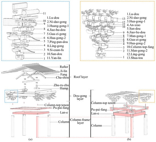
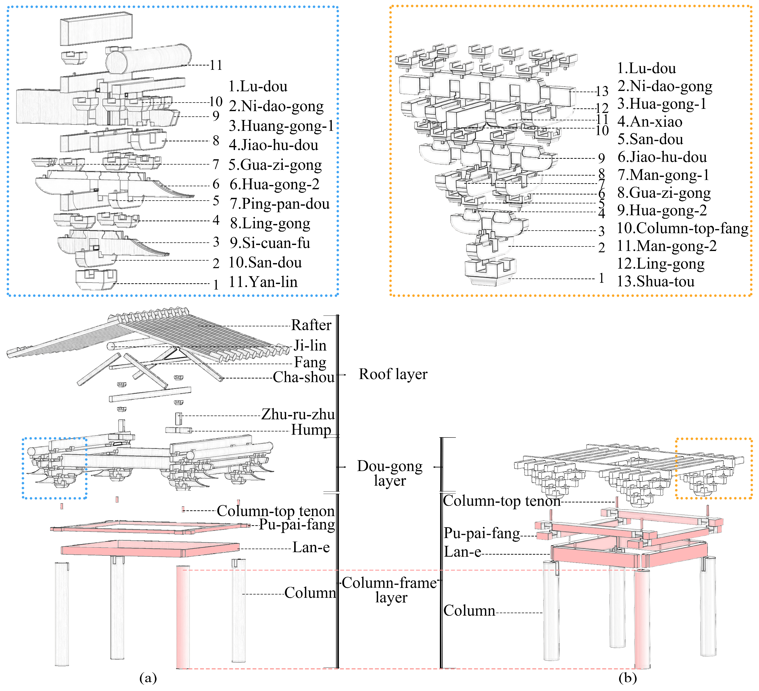
Using the front-eave central beam frame of the Goddess Mother Hall as the prototype, this study designed and fabricated a four-column timber model M1 at a 1:3 scale ratio made of larch (Taiyuan, Chian). The 7th-grade timber frame described in Yingzao Fashi served as the second prototype to produce a timber model M2 at a 1:2 scale ratio with Mongolian pine (Taiyuan, Chian). Both M1 and M2 had free-standing column bases without fixed restraints. The Lan-e were connected to the columns by dovetail joints, Pu-pai-fang boards were mounted on column tops, and Dou-gongs were installed on the Pu-pai-fang. Hidden through-pins were passed through, as shown in Figure 1. Larch was used for M1 to correspond to the timber of the extant Goddess Mother Hall, whereas Mongolian pine was used for M2 because it is commonly adopted in experimental simulations of official Song-style timber structures. The difference in column height between the two models at 1:3 and 1:2 scales is only 6.67%, which can be used as a reference to more easily observe the difference in the other construction dimensions.
Figure 1.
Component names of the models: (a) M1; (b) M2.
The dimensional parameters of M1 and M2 are listed in Table 1. The dimensions and proportional relationships of the two models are similar but not identical. This similarity reflects shared design logic, whereas the differences reflect adaptive variations between the official norms specified in Yingzao Fashi and the local construction represented by the Goddess Mother Hall. Thus, the two models provide representative cases for examining the dimensional principles of official and local ancient timber frame systems. The absolute differences in the heights of the column-frame and Dou-gong layers between M1 and M2 are within 10% (Table 1), while the difference in the ratio of Dou-gong-layer height to column-frame layer height is only 0.88%. The two structures therefore exhibit highly similar vertical proportions. Accordingly, this study further examines how dimensional parameters, including bay width, E-fang cross-section, and column-top tenon cross-section, are associated with the structural mechanical performance of the two structural systems.
Table 1.
Dimensions of vertical structural layers of M1 and M2. and their differences.
2.2. Test Scheme
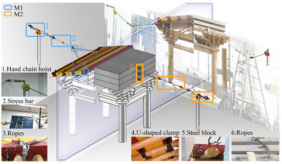
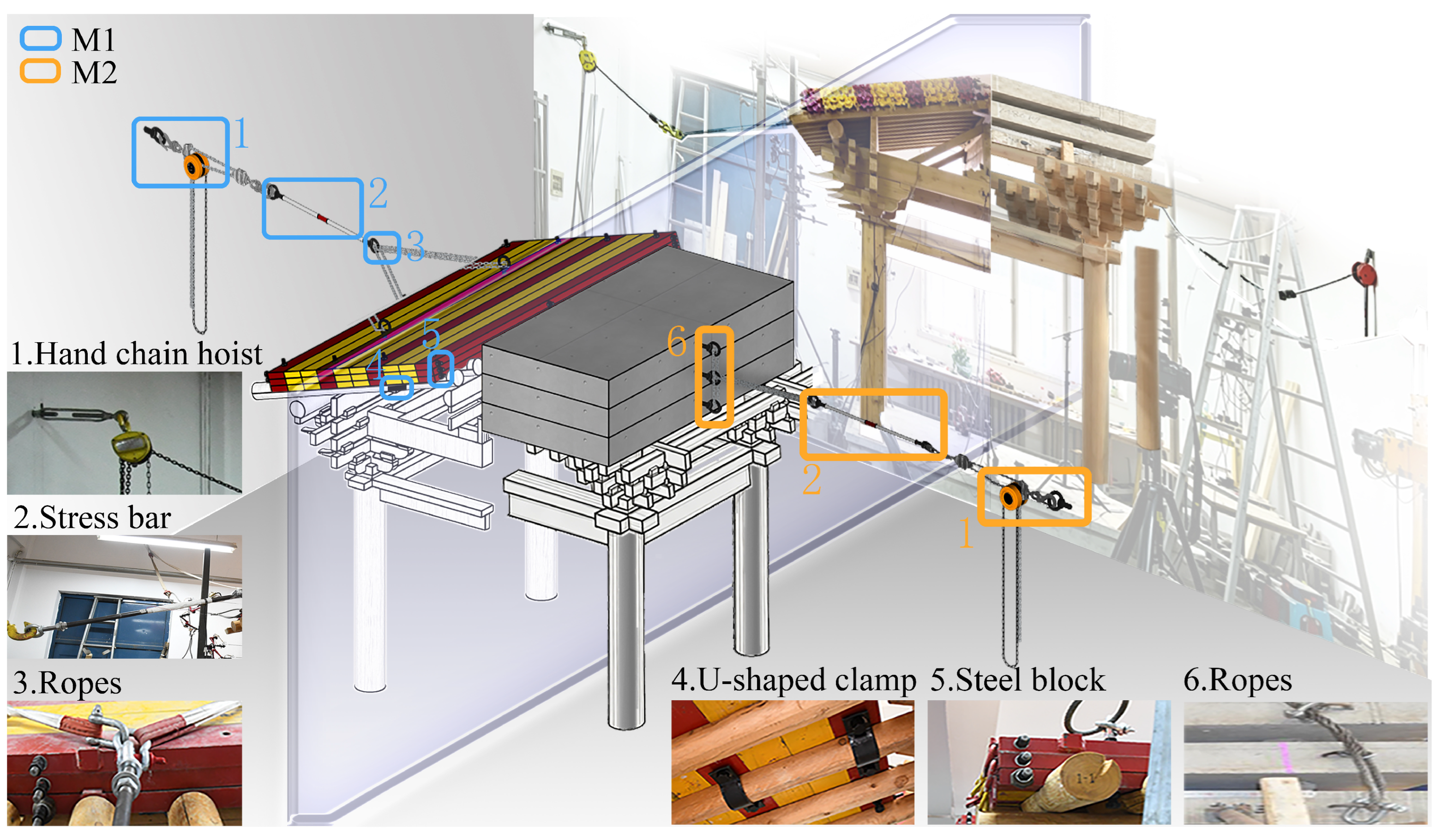
Horizontal cyclic quasi-static loading tests T1 and T2 were conducted on M1 and M2, respectively, and the loading setup is shown in Figure 2. Based on the similitude criterion that accounts for material strength and geometric dimensions (Equation (1)) [30], together with calculations and reductions in roof loads reported for ancient timber buildings of comparable dimensions [31,32], the maximum vertical loads were set to 54 kN for M1 and 45 kN for M2.
Figure 2.
Loading setup.
CN is the similarity coefficient of column axial force; Cσ is the similarity coefficient of compressive strength parallel to the grain; and Cd is the similarity coefficient of column diameter.
To investigate the seismic performance of timber frames under different vertical loads, three vertical-load levels were applied to each model. The corresponding loads for M1 were 18 kN (Level 1), 36 kN (Level 2), and 54 kN (Level 3); those for M2 were 15 kN (Level 1), 30 kN (Level 2), and 45 kN (Level 3). For T1, 60 steel blocks measuring 2200 mm × 40 mm × 20 mm were stacked in layers to provide a total load of 54 kN. For T2, three 15 kN concrete slabs were added sequentially to provide a total load of 45 kN.
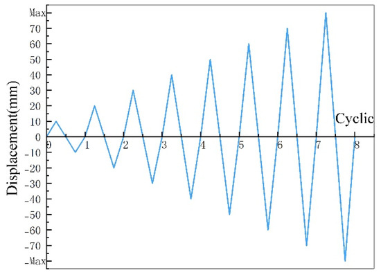
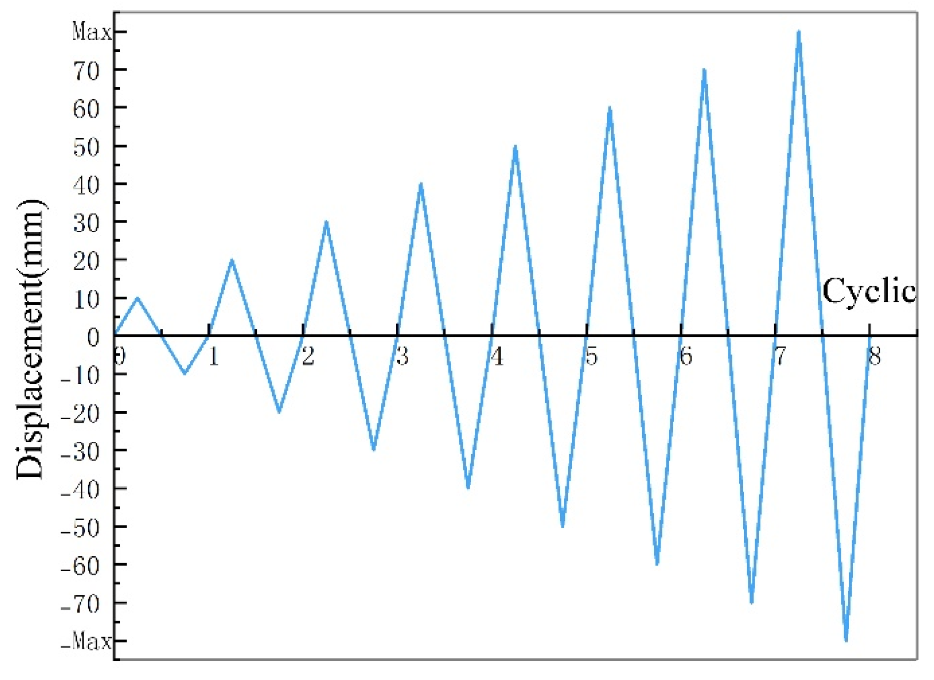
The ultimate horizontal displacement of a four-column timber structure is approximately equal to the column radius [33]. The column radius of M1 is 89 mm, and that of M2 is 97 mm. Accordingly, the estimated ultimate displacement ranges are 80–90 mm for T1 and 90–100 mm for T2. Both tests comprised eight levels of reversed cyclic loading (C1–C8), with horizontal displacement amplitudes set at 10 mm, 20 mm, …, up to the ultimate state (Max). The horizontal cyclic loading time–history curves for T1 and T2 are presented in Figure 3.
Figure 3.
Horizontal cyclic loading time–history curve.
2.3. Data Acquisition and Analysis
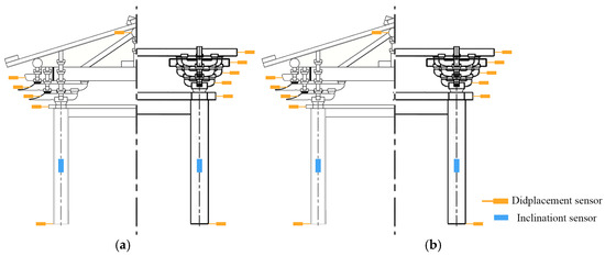
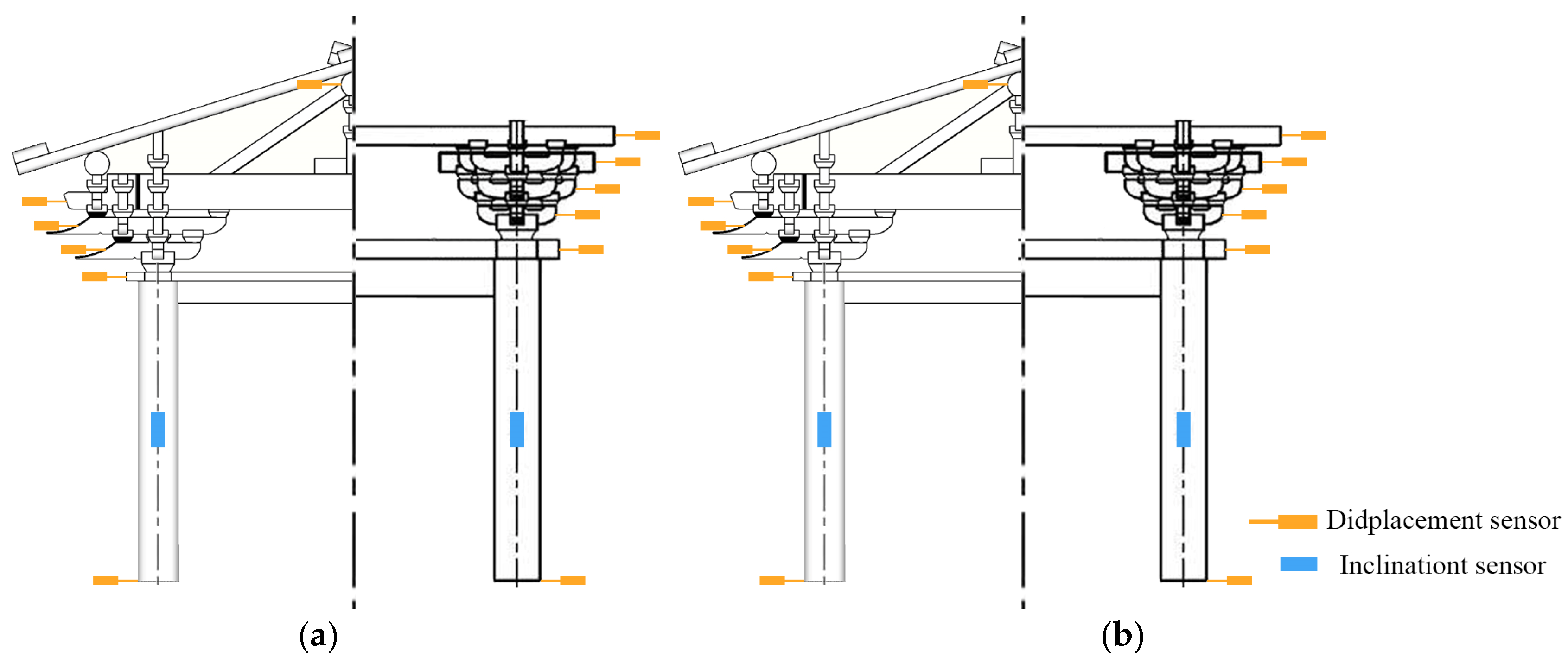
The load was measured using stress bars (Manufactured by the authors) installed between the timber frame and the reaction wall (Figure 2). To investigate the structural performance of the column-frame and Dou-gong layers, horizontal displacement transducers were mounted at the ends of the relevant components in M1 and M2 to record the horizontal displacement (Bengbu Dayang Sensor System Engineering Co., Ltd., Bengbu, China) (Figure 4). For both models, displacement transducers were arranged at the same elevation on all four columns, and the displacement at each height was calculated as the average of the four measurements. Inclinometers (Bengbu Dayang Sensor System Engineering Co., Ltd., Bengbu, China) were mounted on each column shaft, as shown in Figure 4, to record column tilt.
Figure 4.
Instrumentation layout: (a) south side; (b) north side.
Larch generally has a higher density and elastic modulus than Mongolian pine, which may result in higher initial stiffness and lower deformability under the same load. The lower coefficient of friction of Mongolian pine may also affect sliding and energy dissipation at the mortise–tenon joints. In addition, the different scale ratios produce dissimilar scaling effects on gravity loads and flexural stiffness, potentially altering the relative contributions of member bending and joint rotation. To mitigate the effects of differences in material properties and scale ratios on the test results, the relative ratio method was adopted to analyze mechanical performance. The seismic-performance indicators of the column-frame and Dou-gong layers were expressed as ratios relative to the corresponding indicators of the overall frame, thereby converting absolute physical quantities into dimensionless values for cross-model comparison.
3. Results
3.1. Test Deformation Characteristics
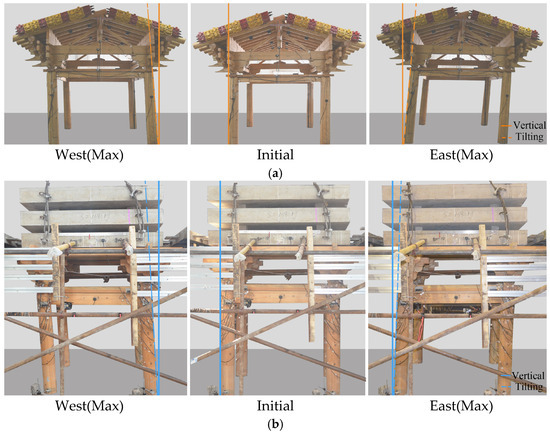
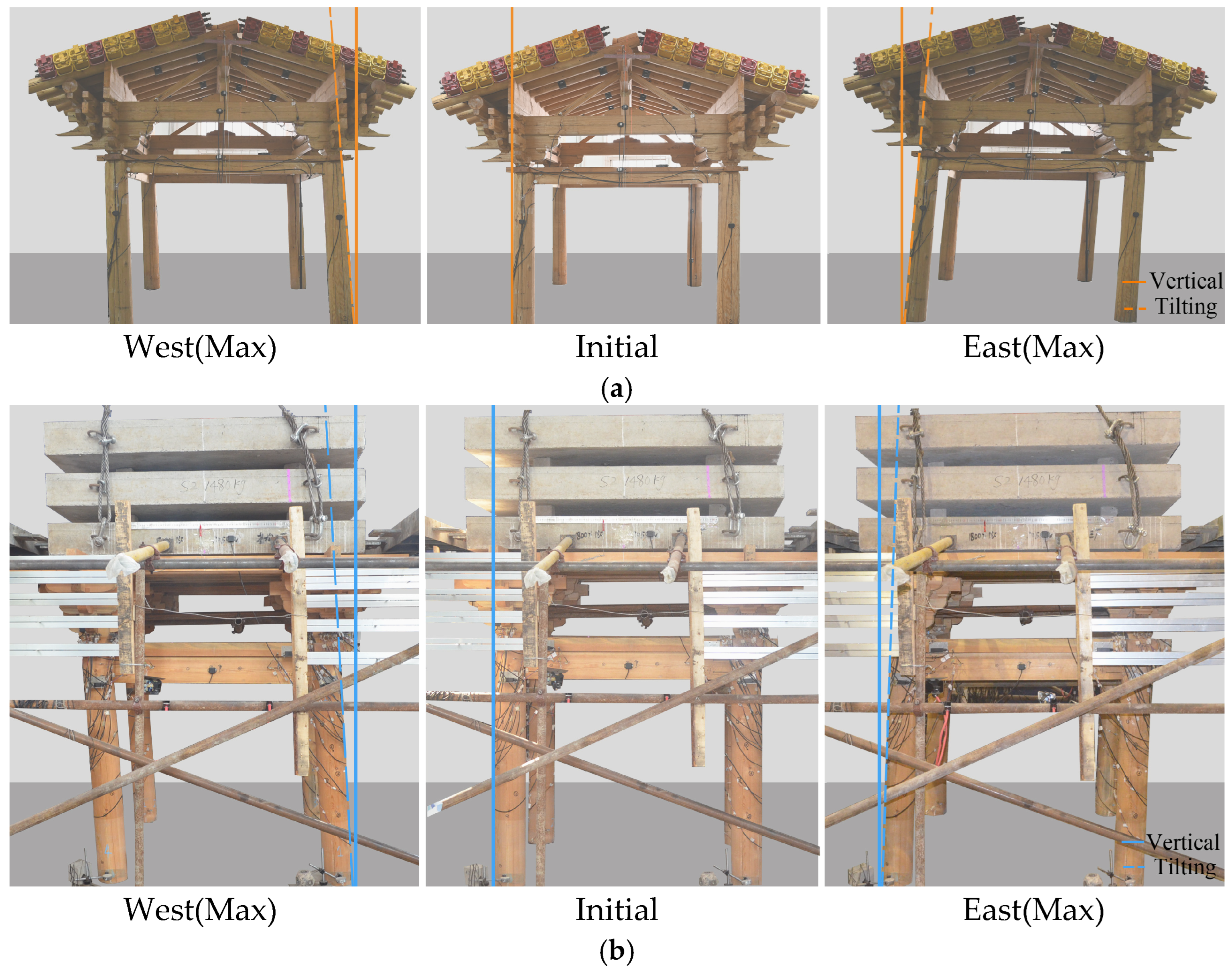
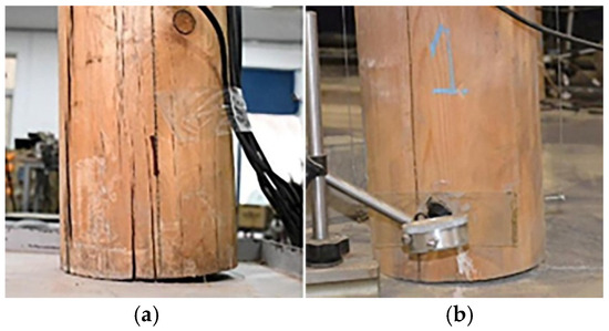
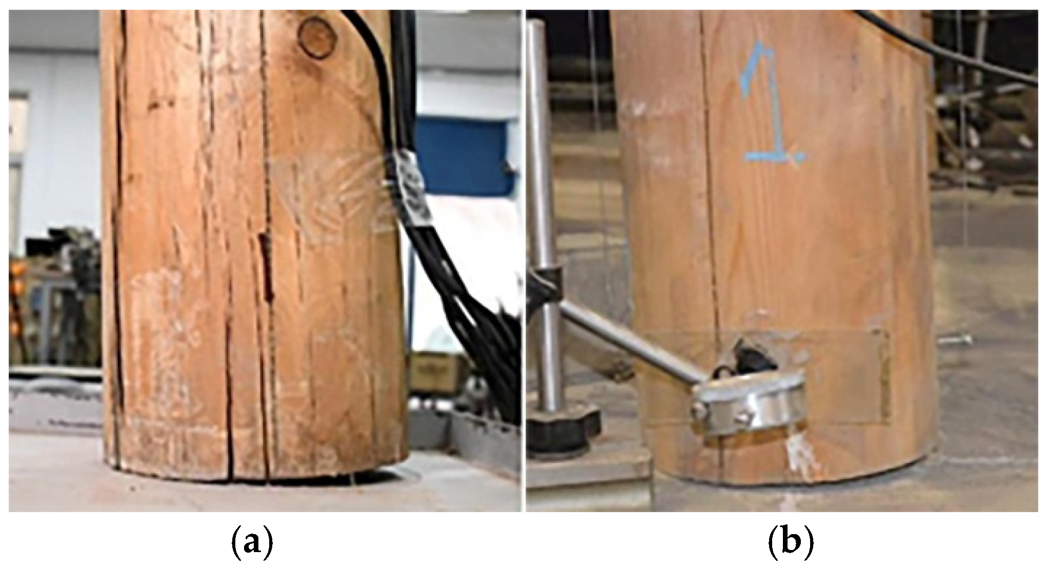
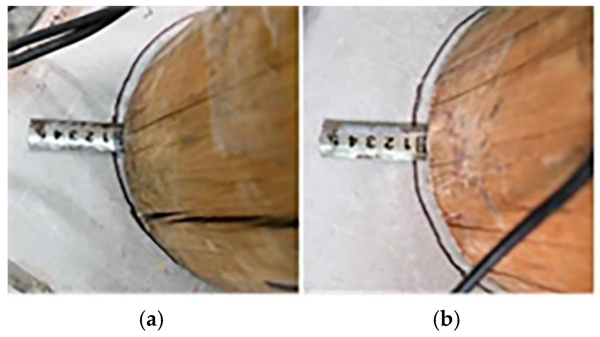
During the tests, the columns of both M1 and M2 exhibited pronounced tilting, whereas the other components moved horizontally as an integrated assembly (Figure 5). Column tilting was accompanied by evident uplift at the column bases. Figure 6 shows the uplift deformation of the column bases when the horizontal displacement reached its max under Level 3.
Figure 5.
Overall structural deformation: (a) M1; (b) M2.
Figure 6.
Uplift deformation of the column bases: (a) M1 Column 1; (b) M2 Column 1.
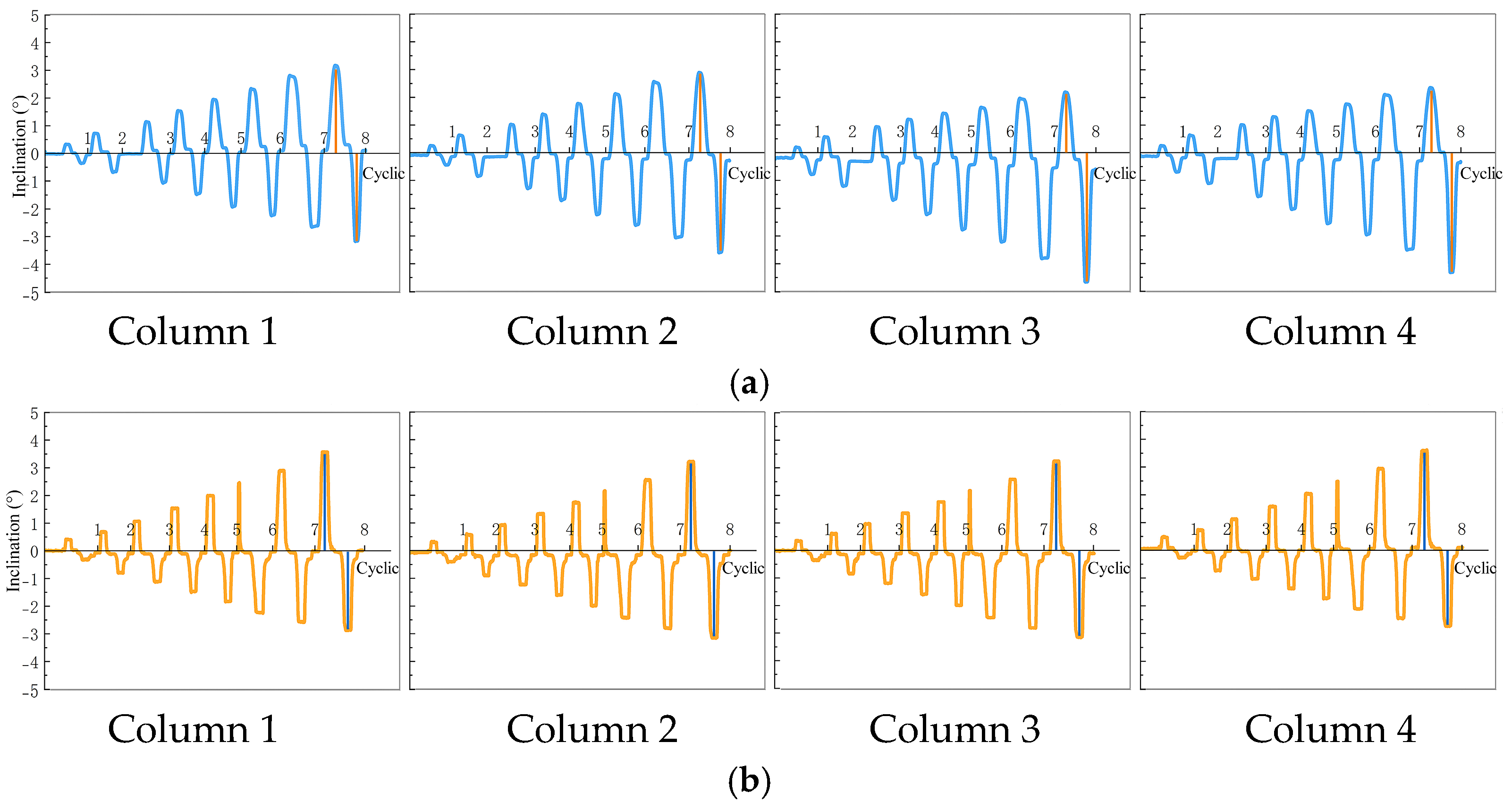
Under Level 3, the variations in column tilt recorded by inclinometers are shown in Figure 7. The tilt amplitude of each column in M1 and M2 increased gradually with the increasing loading cycles, indicating a cumulative tilt effect. The column tilt time–history curves for M1 exhibited substantial dispersion. Except for Column 1, which showed an approximately symmetric curve with a difference of only 0.25% between the maximum positive and negative tilts, Columns 2, 3, and 4 exhibited substantially larger differences of 19.76%, 53.20%, and 45.62%, respectively. The peak tilt angles and cyclic deformation amplitudes also differed markedly among the columns, producing an asymmetric overall distribution. By comparison, the tilt responses of the M2 columns were highly symmetric and synchronous. During horizontal cyclic loading, the positive–negative peak tilt angles were nearly identical. As the loading cycles progressed, the tilt amplitudes of all columns increased uniformly and synchronously, without evident divergence among the responses.
Figure 7.
Column tilt deformation: (a) M1; (b) M2.
After the tests, M1 exhibited evident sliding at the column bases, and the measured offsets are summarized in Table 2. Columns 1 and 3 showed substantial offsets, with clear relative movement between the column bases and the plinth surfaces (Figure 8). Columns 2 and 4 also exhibited smaller offsets of different magnitudes. All column bases underwent irreversible relative sliding in the direction of the horizontal thrust, although the sliding magnitudes differed. By contrast, the column bases of M2 remained stable throughout loading, and no evident sliding or offset was observed. Table 2 shows the sliding displacement of the column bases.
Table 2.
Sliding displacements of the column bases.
Figure 8.
Sliding of M1 column bases: (a) Column 1; (b) Column 3.
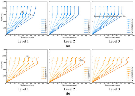
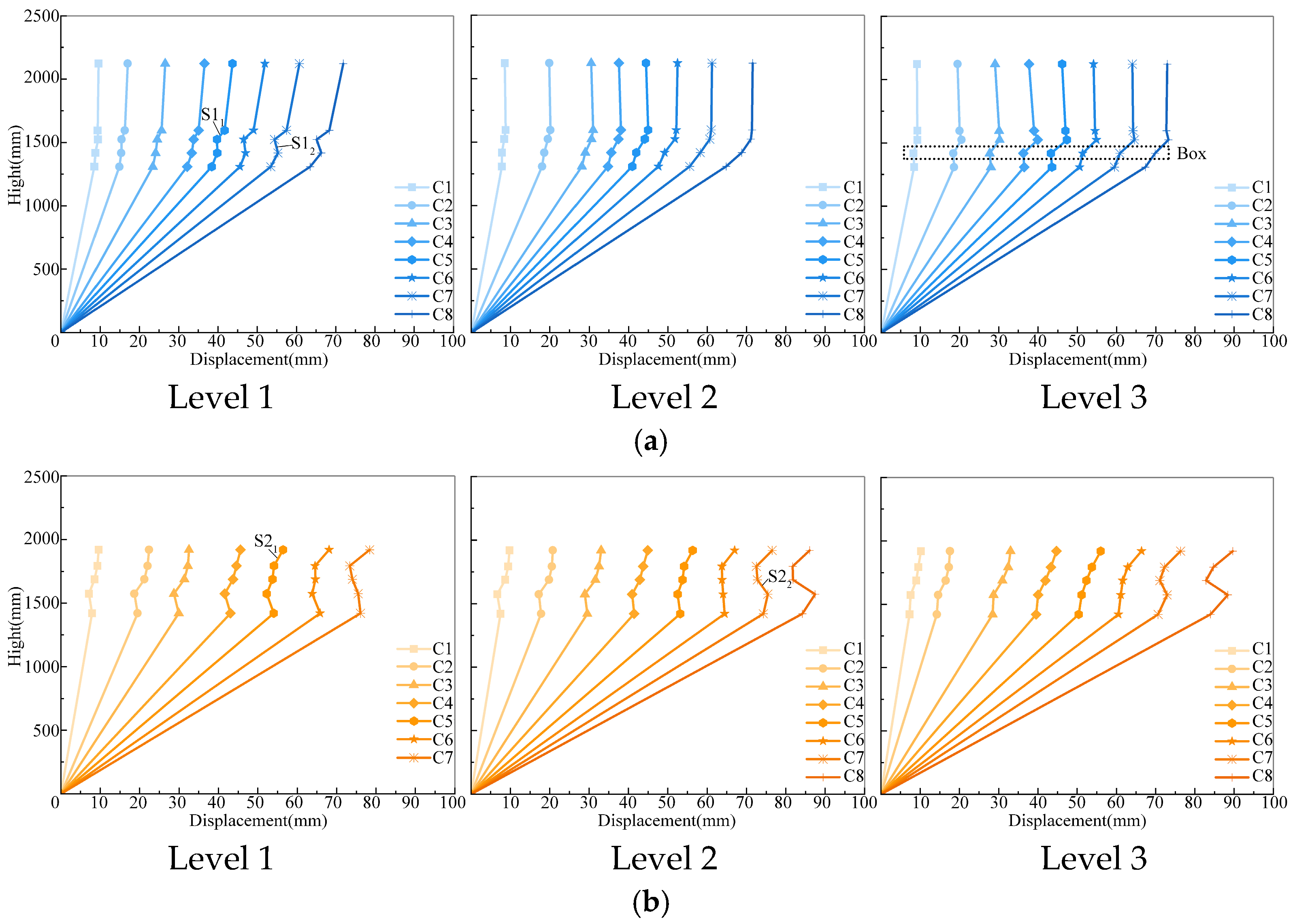
The distribution of horizontal displacement along the structural height is shown in Figure 9. For M1, the measurement points were arranged from bottom to top at the column bases: Pu-pai-fang, Hua-gong-1, Hua-gong-2, Si-chuan-fu, and Ji-lin. The horizontal displacement of the column-frame layer was represented by the displacement at the Pu-pai-fang, whereas that of the Dou-gong layer was defined as the difference between the displacements at the Si-chuan-fu and Pu-pai-fang. For M2, the measurement points were arranged from bottom to top at the column bases: Pu-pai-fang, Ni-dao-gong, Man-gong-1, column-top-fang, and Su-fang. The horizontal displacement of the column-frame layer was represented by the displacement at the Pu-pai-fang, whereas that of the Dou-gong layer was defined as the difference between the displacements at the Su-fang and Pu-pai-fang.
Figure 9.
Distribution of horizontal displacement along structural height: (a) M1; (b) M2.
As shown in Figure 9, under the same vertical-load level, the horizontal deformation of the M1 column-frame layer was slightly greater than that of M2 during the early loading cycles. However, the deformation of M2 increased more rapidly with the loading cycles and eventually exceeded that of M1. The difference between the two models therefore increased as loading progressed. As the vertical load increased, the initial horizontal displacements of the M1 column-frame layer at C1 were 8.54, 7.80, and 8.42 mm, respectively, while the maximum displacement increased from 63.47 to 67.35 mm, an increment of only 6.1%. By contrast, the initial horizontal displacement of the M2 column-frame layer decreased from 7.91 to 7.30 mm. At C8, its displacement reached 84.19 mm under Level 2 and decreased slightly to 83.99 mm under Level 3, indicating only marginal variation. Thus, vertical load had a limited influence on the horizontal deformation of the column-frame layer in both models, which was governed primarily by the imposed horizontal displacement amplitude.
For the M1 Dou-gong layer under Level 1, the displacement curves from C1 to C4 followed an approximately smooth, linear trend, with no evident relative slippage. Irregular segments first appeared between the Si-chuan-fu and Hua-gong-2 at C5 (S11 in Figure 9a), indicating slight slippage. Pronounced slippage occurred between Hua-gong-1 and Hua-gong-2 at C7 (S12 in Figure 9a), and its magnitude continued to increase with horizontal displacement. Under Level 2, the displacement curves of the Dou-gong layer in all loading cycles exhibited an approximately linear and continuous profile without sharp inflection points, and the curves evolved uniformly as a whole. Under Level 3, minor inflection points appeared at the interfaces between Hua-gong-1 and Lu-dou and between Lu-dou and Pu-pai-fang (Box in Figure 9a). For the M2 Dou-gong layer at each load level, the displacement curves from C1 to C4 exhibited curved profiles. Beginning at C5, the displacement curves between the Dou-gong components gradually developed irregular segments. Under Level 1, slight slippage first occurred between Su-fang and column-top-fang at C5 (S21 in Figure 9b). Under Level 2, evident relative slippage developed between Man-gong-1 and Ni-dao-gong at C7 (S22 in Figure 9b), and its magnitude increased with horizontal displacement. Under Level 3, the slippage magnitude remained nearly stable.
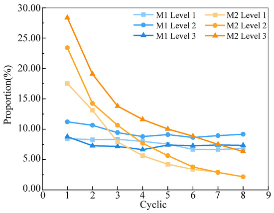
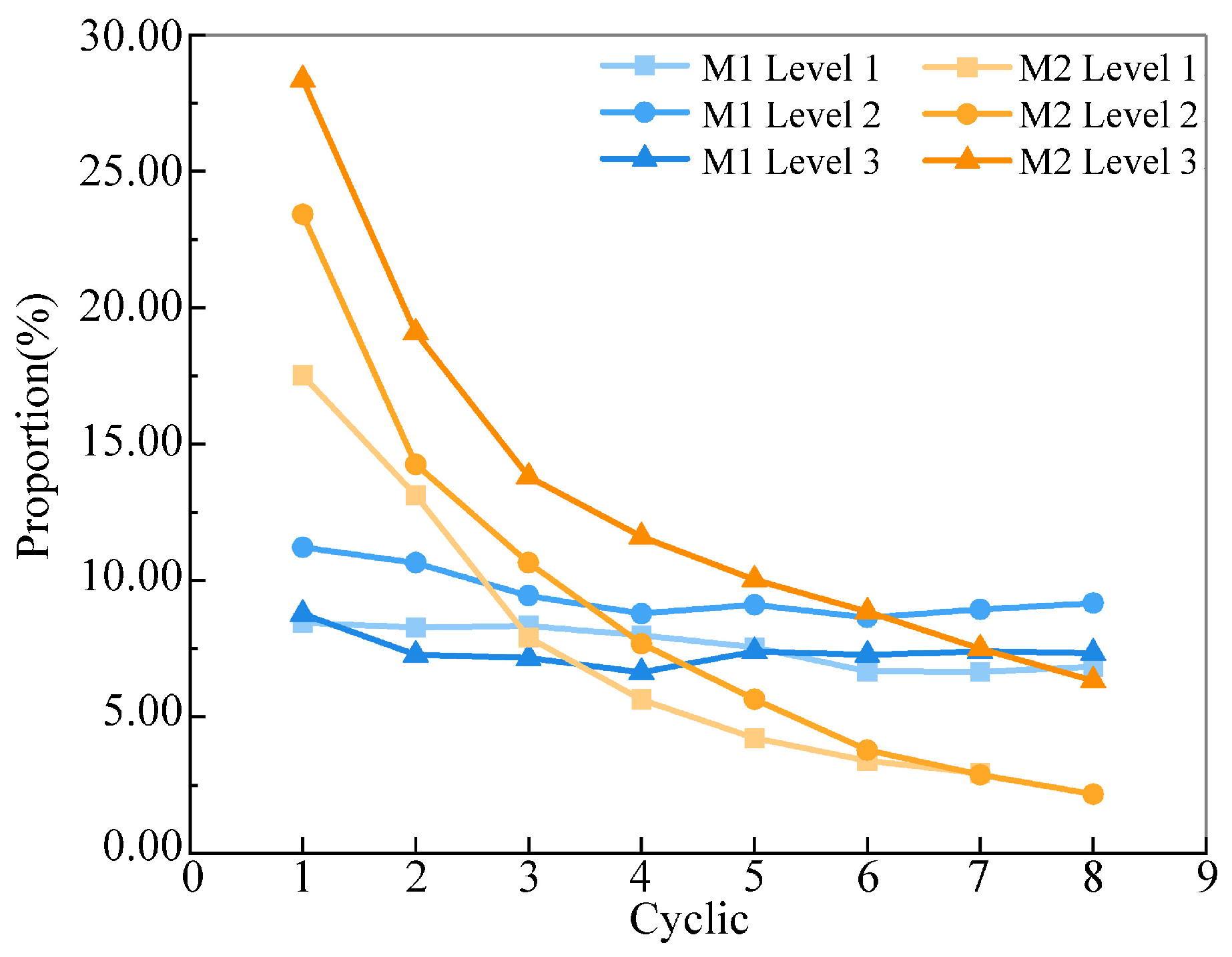
Figure 10 compares the proportions of horizontal displacement contributed by the Dou-gong layers. The interlayer displacement proportion of the M1 Dou-gong layer had a generally low initial value, remaining below 12% under all vertical-load cases. Its reduction with increasing loading cycles was limited, and the curves remained relatively flat, stabilizing at 6–10% during the later cycles. The displacement proportion curves under different vertical loads showed minor differences.
Figure 10.
Proportion of Dou-gong layer horizontal displacement.
By contrast, the initial interlayer displacement proportion of the M2 Dou-gong layer was substantially higher than that of M1, reaching 28.36% under Level 3, which is approximately three times the corresponding value for M1. It decreased approximately linearly as the loading cycles progressed, with a substantially greater reduction than in M1. During the later cycles, the displacement proportion of the M2 Dou-gong layer continued to decrease, and its final stable value fell below that of M1 under the same load condition.
3.2. Mechanical Performance of Column-Frame Layer
The column-frame layer is the primary subsystem responsible for vertical-load transfer and lateral resistance in ancient timber structures. In both M1 and M2, the column-frame layer consists of columns, Lan-e, and Pu-pai-fang, the dimensions and proportional relationships of which strongly influence structural behavior. Among these parameters, the ratio of bay width to column-frame height is a critical index of the geometric configuration of the timber frame. The bay width of M1 is 20.45% greater than that of M2, while its ratio of column-frame height to bay width is 27.37%greater. The cross-sectional areas of the Lan-e and Pu-pai-fang in M1 are 78.74% and 67.74% smaller, respectively, than those in M2, indicating similar levels of difference for the two components (Table 3). Because bay-width proportions affect column stability and the Lan-e and Pu-pai-fang connect the columns and provide coordinated restraint, these parameters should be considered jointly. Accordingly, the wide-bay, thin E-fang configuration of M1 and the narrow-bay, thick E-fang configuration of M2 are expected to influence the lateral stiffness of the timber frames.
Table 3.
Construction dimensions of the column-frame layers and their differences.
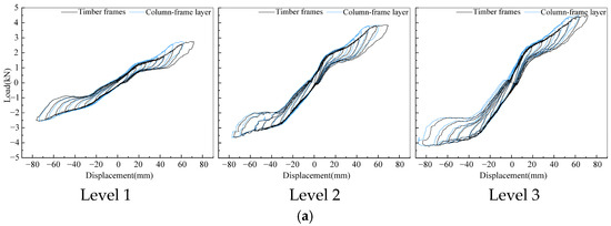
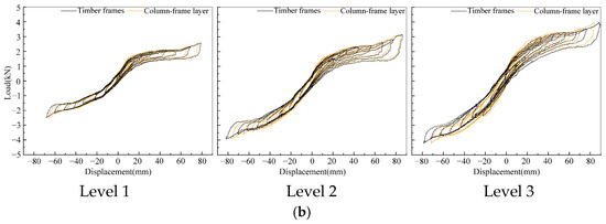
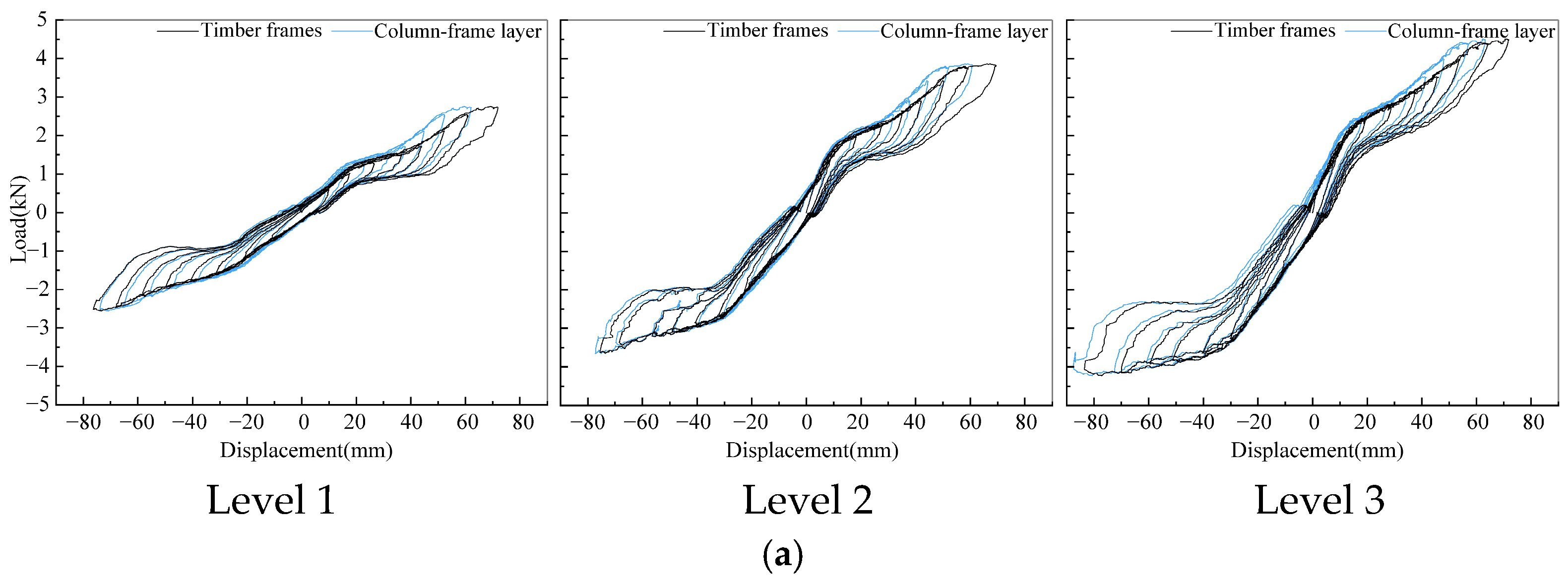
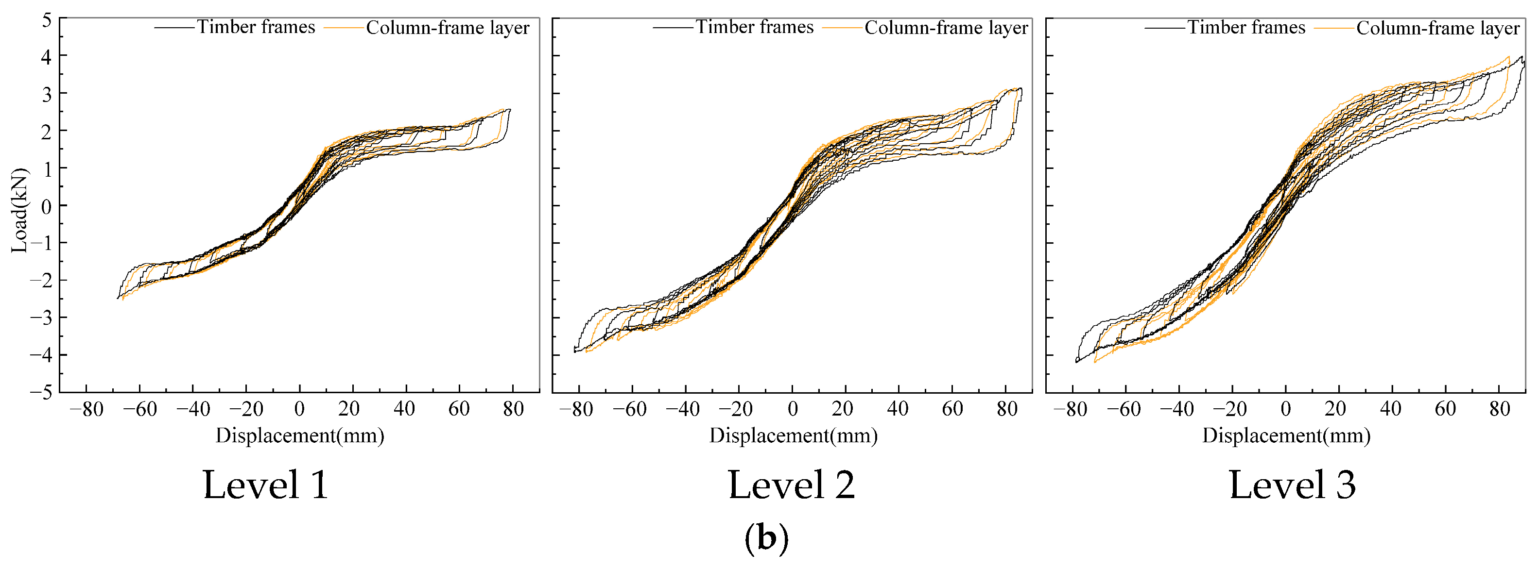
As shown by the hysteretic curves in Figure 11, the responses of the column-frame layer and the overall frame are highly consistent for both M1 and M2, indicating that the column-frame layer makes the primary contribution to overall energy dissipation. All curves exhibit S-shaped loops and pronounced pinching, reflecting the mechanical behavior of ancient timber column-frame layers with semi-rigid mortise–tenon joints. At the same vertical-load level, the pinching of the M1 column-frame layer is substantially more pronounced than that of M2.
Figure 11.
Hysteretic curves of column-frame layer and timber frame: (a) M1; (b) M2.
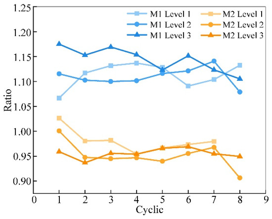
Energy dissipation efficiency was quantified using the equivalent viscous damping coefficient. As shown in Figure 12, the ratio of the coefficient for the M1 column-frame layer to that of the overall frame generally ranged from 1.067 to 1.175. Under Level 3, the ratio was highest in the initial cycle and decreased gradually with subsequent cycles, whereas the ratios under Levels 1 and 2 increased gradually and became more dispersed during the later cycles. For M2, the ratio ranged from 0.906 to 1.026, remained below 1.0 in most cycles, reached its initial-cycle maximum under Level 1, and decreased at all load levels.
Figure 12.
Equivalent viscous damping ratio of column-frame layer to timber frame.
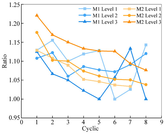
Stiffness performance was evaluated in terms of initial stiffness, its evolution, and the degradation rate. Figure 13 presents the stiffness ratios of the column-frame layer to the overall timber frame, which exceeded 1.0 for both M1 and M2. The initial stiffness ratio of M1 ranged from 1.108 to 1.129, showing little variation with vertical load and indicating a relatively stable contribution to the initial global stiffness. By contrast, the initial stiffness ratio of M2 increased from 1.129 under Level 1 to 1.221 under Level 3, indicating that the contribution of the column-frame layer to the initial stiffness of the overall frame increased with vertical load. The stiffness ratio of M1 fluctuated around 1.0. It generally remained above 1.1 under Levels 1 and 2 but decreased markedly and repeatedly approached 1.0 under Level 3. The ratios of the stiffness-degradation rates were slightly below 1.0 under Levels 1 and 2 and increased to 1.067 under Level 3 (Table 4). For M2, the stiffness ratio increased from Level 1 to Level 3, decreased within each load level, and exhibited only minor fluctuations. The stiffness-degradation-rate ratios remained above 1.0 at all load levels and increased with vertical load (Table 4).
Figure 13.
Stiffness ratio of column-frame layer to timber frame.
Table 4.
Stiffness degradation and difference in column-frame layer to timber frame.
3.3. Mechanical Performance of Dou-Gong Layer
As the key vertical joint connecting the columns to the Dou-gong layer, each column-top tenon transfers vertical loads and horizontal seismic actions and contributes to energy dissipation through compression and friction at the mortise–tenon interface. The cross-sectional areas of the column-top tenons are 855.30 mm2 in M1 and 462.25 mm2 in M2, which is a difference of 85.03%. As key construction dimensions (Table 5), Dou-gong cai height and cai width directly affect the flexural, shear, and bearing capacities of the components and thereby influence the stiffness and energy dissipation of the Dou-gong layer. M1 has a cai height of 72 mm and a cai width of 53 mm, whereas M2 has a cai height of 81 mm and a cai width of 54 mm. The differences in cai height, cai width, and the cai height-to-width ratio are 11.11%, 1.85%, and 9.33%, respectively. Accordingly, M1 is characterized by an almost identical cai width, a slightly reduced cai height, and a flatter cross-section relative to M2.
Table 5.
Construction dimensions of the Dou-gong layers and their differences.
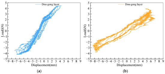
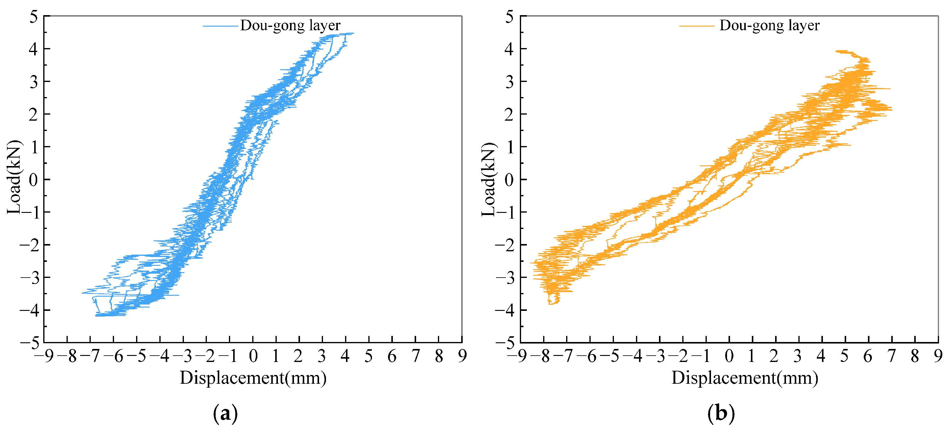
Figure 14 shows the hysteretic curves of the M1 and M2 Dou-gong layers under Level 3. The M1 loops are slender, enclose relatively small areas, and exhibit pronounced pinching, whereas the M2 loops are substantially fuller and exhibit less pinching.
Figure 14.
Hysteretic curves of Dou-gong layer under Level 3: (a) M1; (b) M2.
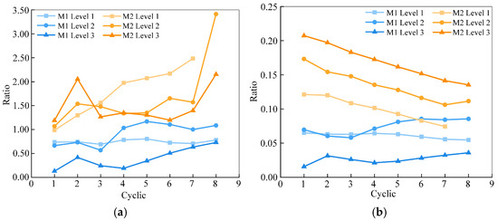
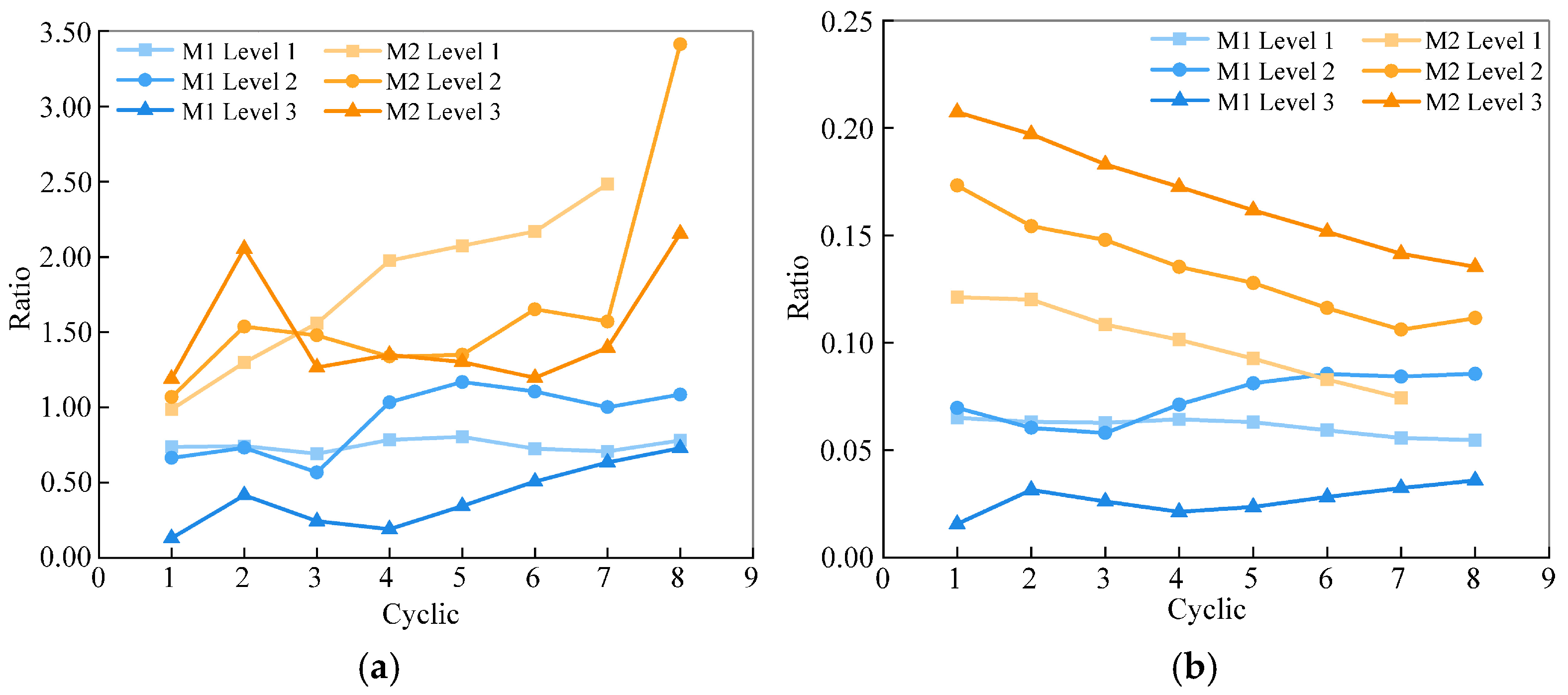
As shown in Figure 15, the ratios of cumulative energy dissipation and the equivalent viscous damping coefficient of the Dou-gong layer to those of the overall frame are markedly higher for M2 than for M1. The cumulative-energy dissipation ratio of the M2 Dou-gong layer is approximately one to three times that of M1 under Levels 1 and 2 and more than three times that of M1 under Level 3. By contrast, the M1 ratio decreases to 1.56–3.60% under Level 3, below its Level 1 range. The ratio of the equivalent viscous damping coefficients exhibits a similar trend. For M1, the ratio ranges from 0.692 to 0.805 under Level 1; only a few cycles exceed 1.0 under Level 2; and the ratio decreases to 0.132–0.730 under Level 3. For M2, the mean ratios under Levels 1, 2, and 3 are 1.79, 1.68, and 1.49, respectively; these values are substantially higher than those for M1 and remain relatively stable.
Figure 15.
Energy dissipation capacity of Dou-gong layer and timber frame: (a) equivalent viscous damping ratio; (b) cumulative energy dissipation ratio.
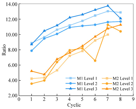
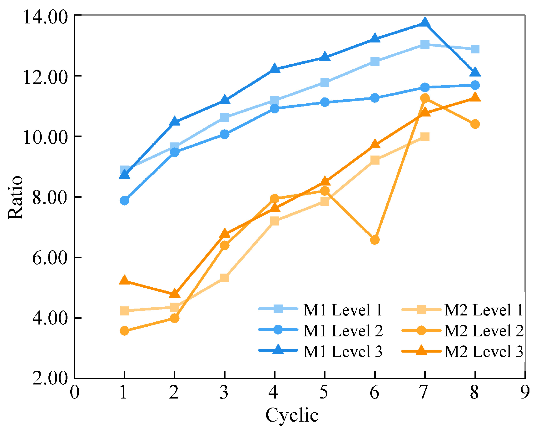
Figure 16 compares the ratios of Dou-gong-layer stiffness to overall-frame stiffness for M1 and M2. During the early loading cycles, compression and interlocking among the mortise–tenon joints increased, progressively mobilizing the stiffness of the Dou-gong layer. During the later cycles, the Dou-gong layer entered the elastoplastic range, and its stiffness began to degrade. The stiffness ratio of the M1 Dou-gong layer was consistently higher than that of M2 throughout loading. The M1 ratio increased smoothly and steadily. Particularly under Levels 2 and 3, it remained high with only small fluctuations. By contrast, the M2 stiffness ratio reached 8.194 at C5 under Level 2, decreased sharply to 6.576 at C6, and then peaked at 11.255 at C7, corresponding to a fluctuation amplitude of 41.57% and indicating substantial variability during the increasing phase.
Figure 16.
Stiffness ratio of Dou-gong layer to timber frame.
4. Discussion
4.1. Mechanistic Interpretation of Deformation Characteristics
Experimental observations show that M1 exhibits greater variation in column tilt amplitudes and more pronounced sliding at the column bases than M2. It is inferred that the wide-bay, thin E-fang configuration of M1 may provide lower lateral restraint than that of M2, weaken the coordinated action of the column-frame layer and increase structural deformability, while potentially increasing susceptibility to overall overturning and torsion. By contrast, the narrow bay and thick E-fang of M2 are likely to enhance transverse restraint and improve the overall stability of the timber frame.
Previous studies have confirmed that column rocking and column-base sliding are essential components of the horizontal deformation of timber structures [15,16], which is consistent with the deformation pattern observed in both models in this study, where column inclination was accompanied by column-base sliding. Experiments have also shown that increasing column height progressively reduces the overall lateral resistance of timber frames [26,27]. In M1, the wide bay and thin E-fang appear to offer more space for independent rocking of the columns, which is similar to increasing their effective height. This mechanism is consistent with the more dispersed column-tilt responses observed in M1 than in M2.
The initial proportion of horizontal displacement contributed by the M1 Dou-gong layer is low, and the corresponding curve is relatively flat. Under Level 2, relative interlayer sliding largely ceases and is replaced by coordinated translation of the layer as a whole. Under Level 3, internal sliding within the Dou-gong layer is fully developed, while only minor sliding occurs at the interface between the Dou-gong and column-frame layers. By contrast, coordinated interlayer sliding among the components of the M2 Dou-gong layer remains evident under Level 3. The displacement–proportion curve of the M2 Dou-gong layer maintains a downward trend throughout loading and flattens more slowly than that of M1, indicating a slower stabilization process. Based on the above observations, it is inferred that the slightly reduced cai height, flatter cross-section, and enlarged cross-sectional area of the column-top tenons in M1 are associated with greater connection integrity and reduced progressive interlayer sliding, whereas the standardized cai height-to-width ratio in the official norm model may permit more pronounced progressive sliding of the Dou-gong layer.
Previous experimental studies have emphasized that sliding deformation is an important component of the lateral deformation of the Dou-gong layer [22]. In both models investigated in this study, sliding occurred among the components within the Dou-gong layers. The deformation capacity of the Dou-gong decreases with an increase in the number of connection members [21]. The official norm Dou-gong of M2 developed progressive interlayer sliding throughout loading, whereas the strengthened restraint provided by the enlarged column-top tenons in M1 could have caused interlayer sliding to terminate earlier and transition into overall translation. This phenomenon is consistent with the mechanism reported in previous studies.
M1 and M2 differ in timber species and geometric scale. Although the relative ratio method mitigates the effects of material and scale differences on the macroscopic test results, it cannot fully eliminate the effects of differences in the friction coefficient, elastic modulus, and inertia on local deformation. Factors such as eccentric loading of the test rig and manufacturing errors in the models may also induce torsional behavior. The inferences regarding column tilting, sliding at the column bases and interlayer sliding within the Dou-gong are based primarily on correlations between the observed deformation and dimensional differences. Because these inferences are not supported by direct measurements of joint rotational stiffness or contact stress, they should be regarded as trend-based and require further verification through controlled-variable tests or refined joint tests.
4.2. Analysis of Differences in Mechanical Performance
The experimental data show that the ratio of the equivalent viscous damping coefficient of the M1 column-frame layer to that of the overall frame remained above 1.0 at all load levels, whereas the corresponding ratio for M2 was consistently lower than that for M1. The energy dissipation efficiency of the M1 column-frame layer consistently exceeded that of the overall frame. Under all vertical-load conditions, the M1 ratio remained generally stable with limited fluctuation as the loading cycles progressed, whereas the M2 ratio showed an overall decreasing trend. Under low and medium loads, the M1 column-frame layer maintained a favorable stiffness contribution, with slightly slower stiffness degradation than the overall frame and good structural integrity. Under high loads, however, its stiffness contribution decreased rapidly and its degradation accelerated. The stiffness contribution of the M2 column-frame layer increased with the vertical-load level. Its stiffness degraded faster than that of the overall frame at all load levels, and this difference became more pronounced as the load increased. It is inferred that the wide bay of M1 is likely associated with greater frame deformation, while the thin E-fang appears to reduce the restraint between the columns and E-fang, thereby possibly contributing to greater energy dissipation efficiency. The narrow bay and thick E-fang of M2 may enhance transverse restraint and stiffness but limit the independent deformation and energy dissipation of the column-frame layer.
Traditional timber structures can dissipate seismic energy through mechanisms including column rocking, mortise–tenon joint rotation, and frictional effects [26]. It is therefore inferred that the wide bay and thin E-fang configuration of M1 is likely associated with weaker transverse restraint and permits more sufficient relative rotation and frictional energy dissipation, which is consistent with the experimental result that the energy dissipation efficiency of the M1 column-frame layer remained higher than that of M2. Under cyclic loading, traditional timber structures exhibit evident stiffness degradation, and the degradation rate is closely related to load amplitude and joint configuration [18,34]. The increase in the stiffness contribution of the M2 column-frame layer with increasing load and the rapid stiffness degradation of the thin E-fang M1 column-frame layer under high loads can be interpreted in relation to this mechanism. Meanwhile, numerical simulations have shown that seismic performance is relatively stable when the ratio of column height to Ming-jian width ranges from 0.7 to 0.8 [25]. The difference between M1 and M2 in this ratio is consistent with the trend reported in that numerical study.
The experimental data also show that the ratios of the equivalent viscous damping coefficients and cumulative energy dissipations of the M1 Dou-gong layer were markedly lower than those of M2 at all load levels, indicating that the M2 Dou-gong layer made a greater relative contribution to energy dissipation. The M1 Dou-gong layer exhibited a higher ultimate bearing capacity, and its stiffness contribution increased slowly and steadily with the loading cycles, whereas that of M2 increased more rapidly but was less stable. It is inferred that the enlarged cross-sectional area of the column-top tenons in M1 may contribute to a relatively rigid connection between the Dou-gong and column-frame layers. This reinforcement could increase stiffness but may also restrict independent sliding and rotation between the Dou-gong layer and the column tops, thereby potentially limiting energy dissipation through friction and compression. Although the slightly reduced cai height and flatter cross-section may facilitate deformation, the larger contact area of the column-top tenons possibly restricts local rotation and sliding under high loads, thereby reducing energy dissipation efficiency.
An increase in joint clearance can improve structural deformability but reduce stiffness [20], indicating that strengthened joint configurations may enhance the stiffness contribution of the Dou-gong layer. This is consistent with the stable increase in the stiffness contribution observed in the M1 Dou-gong layer after enlargement of the column-top tenon cross-section. By contrast, although the stiffness contribution of M2 increased more rapidly, its stability was relatively lower. Previous research has also shown that increasing tenon pull-out length significantly reduces the energy dissipation capacity and rotational stiffness of joints [29]. These findings suggest that moderate sliding may be an important energy dissipation mechanism in the Dou-gong layer. In the present study, M2 has a smaller cross-sectional area of the column-top tenons and is likely to permit greater independent sliding of the Dou-gong layer; its energy dissipation capacity is therefore greater than that of M1, which has larger column-top tenons.
However, several construction parameters, including bay width, E-fang cross-section, Dou-gong cai height-to-width ratio, and cross-sectional area of the column-top tenons, vary simultaneously between the two models. The test results therefore reflect the combined effects of these parameter changes. Because no single-parameter control conditions were included, the observed differences in mechanical performance cannot currently be attributed definitively to any specific dimensional parameter.
5. Conclusions and Prospects
This study conducted horizontal cyclic quasi-static loading tests on a scaled model of the Song dynasty Goddess Mother Hall of Jinci and on a model of a 7th-grade timber frame described in Yingzao Fashi, which share similar assembly logic. The study systematically compared the key dimensional parameters of the two models and examined the associated differences in the mechanical performance of the column-frame and Dou-gong layers, thereby identifying relationships between construction dimensions and mechanical performance in local practices and official norms. The experimental data led to the following conclusions:
- Compared with the Yingzao Fashi model, the wide-bay and thin E-fang configuration of the Goddess Mother Hall of Jinci is associated with higher energy dissipation efficiency of the column-frame layer but lower stiffness stability under high loads.
- The combination of an enlarged column-top tenon cross-section, slightly reduced cai height, and a flattened cross-section in the Goddess Mother Hall of Jinci corresponds with a stable increase in the stiffness contribution of the Dou-gong layer while limiting its energy dissipation capacity.
The results suggest that local and official construction practices for Song-dynasty timber buildings differ in their dimensions and that the coupling of multiple dimensional differences produces corresponding changes in mechanical performance. This finding is supported by the comparative mechanical responses of the Goddess Mother Hall and the Yingzao Fashi model, and the possible factors underlying these changes are correlated and interpreted. Nevertheless, owing to material heterogeneity in the scaled models, the limited representativeness of the samples, and the unresolved coupling among multiple parameters, the conclusions apply only to the two specific models examined here. Future research should use controlled variable tests to quantify the mechanical effect of each construction parameter individually, expand the sample to architectural forms from different regions and cai grades, and further verify the performance differences between official and local construction systems, thereby providing a more comprehensive theoretical basis for the conservation and repair of historic timber structures.
Author Contributions
Conceptualization, Y.W.; Methodology, Y.W. and C.Z.; Investigation, Y.W., S.W. and L.L.; Resources, C.Z. and X.M.; Writing—original draft preparation, Y.W. and S.W.; Writing—review and editing, Y.W., C.Z. and X.M.; Visualization, Y.W., S.W. and L.L.; Supervision, C.Z. and X.M.; Funding acquisition, C.Z. and X.M. All authors have read and agreed to the published version of the manuscript.
Funding
This research was funded by the Shanxi Provincial Basic Research Program for Young Scientists (Project: Research on the Convergence and Divergence Mechanisms of Vernacular Architectural Construction Techniques in Shanxi) under Grant No. 202303021212062; the National Natural Science Foundation of China under Grant No. U2574206; and the Basic Research Program of Shanxi Province under Grant No. 202403021212329.
Data Availability Statement
Data is contained within the article.
Acknowledgments
We acknowledge any support given which is not covered by the author’s contribution or funding sections.
Conflicts of Interest
The authors declare no conflicts of interest.
References
- Yuan, Y. A Study on the formation of eight-grades values in Yingzao Fashi. J. Archit. Hist. 2025, 6, 151–160. [Google Scholar]
- Zhang, S. Discussion on Cai as benchmark in the design system of timber frame in Ying Zao Fa Shi. Archit. Hist. 2016, 73–81. [Google Scholar]
- Zhao, M. Study on the construction modulus in Yingzao Fashi. Archit. J. 2011, 72–75. Available online: https://kns.cnki.net/kcms2/article/abstract?v=iAN2XHIMbKt1aBnxv6iSL_ZF95wHb0Q0ESU3dLN8xt7_0MlDk8SQI0EL-y0Szu0vV_fTwf3ipdsw8GfIrkFHxzlB3N7Lr1txkf81VwCQVtYh_NFqUuNcheVrhCB0dQIGCvdTsYG6tuZJ0rlOrBNgcHGJuvrL9M3VXozRmRN1boJVv9geT0iB7DFiyv6fnhg6&uniplatform=NZKPT&language=CHS (accessed on 23 November 2024).
- Shevchenko, M. The Origin of Modularity in China’s Normative Architecture. In Proceedings of the 4th International Conference on Architecture: Heritage, Tradition and Innovation, Online, 10 January 2023. [Google Scholar]
- Zhu, Y. Adjustable scale and construction scale in the wooden structure of Yingzao Fashi and its answers to three basic questions. Architect 2021, 83–89. Available online: https://kns.cnki.net/kcms2/article/abstract?v=iAN2XHIMbKtbnDeMZZX0whqid3hDWLstSA_8WjZb5vd32PZgdnPu7lPm86gIwIr3O6c0x45EeKn0pJyIIKMXiZNGv6MxTTF1W1pQ8FPuBYjH33wbXl2W7UerT8W3bhx21B8jUsCOlhLaHPd3Vo-ahPawRAVsTegizddmElJUo6_TtjjL07dOstHNAqUx5k6a&uniplatform=NZKPT&language=CHS (accessed on 23 November 2024).
- Cheng, J.; Chen, D. Cai, Dou, rafter intervals, and standard units: Modular system in Chinese ancient architectural design. Herit. Archit. 2022, 45–55. [Google Scholar] [CrossRef]
- Kim, B. Using the Yingzao Fashi to Analyze Architectural Elements in Japanese and Korean Buildings: Comparing the Yingzao Fashi’s Specifications with the Dimensional Properties of Historic Buildings. Architecture 2025, 5, 67. [Google Scholar] [CrossRef] [Scilit]
- Li, H. The Different Functions of Cai, Qi and Fen Applied in the Greater Carpentry of the Yingzao Fashi. J. Archit. Plan. (Trans. AIJ) 2013, 78, 1171–1177. [Google Scholar] [CrossRef] [Scilit]
- Yu, L.; Xu, Y. Discussion on the Timber Structure Materials and Ruler System of the Main Hall of Jiwang Temple in Wanrong, Shanxi. Bull. Natl. Mus. China 2015, 128–146. Available online: https://kns.cnki.net/kcms2/article/abstract?v=pX0ZfcSLBkVNEhmFejwpoNmvo71tejTEJoung2gw0BQ7C4juHsJ5wLTEB9UVh5uPf0Z5GcJw230BMEHFwoOIDxWCiWnMuq-SzODYwVkzy7ztVnGa_3K8b_QRC57ZZe3XhFG3agLbSqRcDxS8H7bSogMXxCBbJej6vu-LXqsBqAf3_R5tZxKvvn-jWSRpYftd&uniplatform=NZKPT&language=CHS (accessed on 24 August 2026).
- Wang, Y.; Xu, Y. A Study on the “Large Ruler” and Scale Composition in Liao Dynasty Architecture: Taking the Liao Structures of Dule Temple, Fengguo Temple, and Kaishan Temple as Examples. Palace Mus. J. 2023, 24–47, 150. [Google Scholar] [CrossRef]
- Zhao, S.; Li, Z.; Liu, C. Tracing the Carpenter’s Craft: The Algorithm of Dougong with Seven Puzuo and Lower Ang in the Maitreya Hall of Chongfu Temple, Shuozhou. J. Archit. Hist. 2025, 6, 119–132. [Google Scholar]
- Wang, G. Analysis of the Materials Used in the Main Hall of Fengguo Temple and the Palace Halls of the Liao, Song, and Jin Periods. J. Archit. Hist. 2020, 1, 40–52. [Google Scholar]
- Jiang, Z. Interpretation of the “Jiadao” Design Phenomenon in Song–Jin Timber Frames in Southeastern Shanxi. J. Archit. Hist. 2024, 5, 40–52. [Google Scholar]
- Zhou, M.; Hu, S.; Zhu, G. Analysis of the Causes of Inclined Beams in Song and Jin Timber Buildings in Central Shanxi. Archit. J. 2018, 32–37. Available online: https://kns.cnki.net/kcms2/article/abstract?v=hH4QDuxDhLSHa2pkdUOk2pDUa_XaRKR0ydTSGYboD-aYHqt_OROIA-ujGSOlEQv7fzJp_y9-Erwo1Vmi-3J4DWNIsBtt7Iud5WkdHO-WCO3tJRh_sccib2mZ7-J7szgi7TVCopGJEM1EspSFHBUqtGdo-YptYa9PapG4sQDZy-Pwy5ehWik7tr_cwTl8B4LZ&uniplatform=NZKPT&language=CHS (accessed on 26 August 2026).
- Meng, X.; Li, T.; Yang, Q. Experimental study on the seismic mechanism of a full-scale traditional Chinese timber structure. Eng. Struct. 2019, 180, 484–493. [Google Scholar] [CrossRef] [Scilit]
- Meng, X.; Yang, Q.; Wei, J.; Li, T. Experimental investigation on the lateral structural performance of a traditional Chinese pre-Ming dynasty timber structure based on half-scale pseudo-static tests. Eng. Struct. 2018, 167, 582–591. [Google Scholar] [CrossRef] [Scilit]
- Chen, J.; Chen, Y.; Shi, X.; Zhao, Y.; Li, T. Hysteresis behavior of traditional timber structures by full-scale tests. Adv. Struct. Eng. 2018, 21, 287–299. [Google Scholar] [CrossRef] [Scilit]
- Chen, J.; Li, T.; Yang, Q.; Shi, X.; Zhao, Y. Degradation laws of hysteretic behaviour for historical timber buildings based on pseudo-static tests. Eng. Struct. 2018, 156, 480–489. [Google Scholar] [CrossRef] [Scilit]
- Li, S.; Zhou, Z.; Luo, H.; Milani, G.; Abruzzese, D. Behavior of traditional Chinese mortise-tenon joints: Experimental and numerical insight for coupled vertical and reversed cyclic horizontal loads. J. Build. Eng. 2020, 30, 101257. [Google Scholar] [CrossRef] [Scilit]
- Zhang, B.; Xie, Q.; Liu, Y.; Zhang, L.; Li, S. Effects of gaps on the seismic performance of traditional timber frames with straight mortise-tenon joint: Experimental tests, energy dissipation mechanism and hysteretic model. J. Build. Eng. 2022, 58, 105019. [Google Scholar] [CrossRef] [Scilit]
- Zhang, L.; Liu, C.; Zhou, T.; Qin, Y.; Gao, S. Experimental and formula deduction on the mechanical performance of Fang in Dou-Gong of Song dynasty. J. Sci. Rep. 2024, 14, 30900. [Google Scholar] [CrossRef] [Scilit] [PubMed]
- Xie, Q.; Wang, L.; Zhang, L.; Xiang, W.; Hu, W. Rotational Behaviors of Fork-Column Dou-Gong: Experimental Tests and Hysteresis Model. J. Perform. Constr. Facil. 2020, 34, 04020032. [Google Scholar] [CrossRef] [Scilit]
- Sha, B.; Xie, L.; Yong, X.; Li, A. An experimental study of the combined hysteretic behavior of dougong and upper frame in Yingxian Wood Pagoda. Constr. Build. Mater. 2021, 305, 124723. [Google Scholar] [CrossRef] [Scilit]
- Sha, B.; Li, A.; Deng, Y.; Xie, L. Study on the damage mechanism and hysteretic performance of fork column-dougong connection in traditional Chinese multi-story wooden structures. J. Build. Eng. 2024, 84, 108502. [Google Scholar] [CrossRef] [Scilit]
- Jiang, P. Taking Yuxian Ancient Stage as an Example to Explore the Influence of the Size Ratio of Ancient Buildings on the Seismic Performance. Master’s Thesis, Hebei University of Architecture, Zhangjiakou, China, 2021. [Google Scholar]
- Xie, Q.; Zhang, L.; Wang, L.; Zhou, W.; Zhou, T. Lateral performance of traditional Chinese timber frames: Experiments and analytical model. Eng. Struct. 2019, 186, 446–455. [Google Scholar] [CrossRef] [Scilit]
- He, J.; Wang, J.; Yang, Q. Experimental study on lateral resistance capacity of column in traditional timber structures considering effects of height-diameter ratio. China Civ. Eng. J. 2018, 51, 27–35. [Google Scholar]
- Hajdarević, S.; Martinović, S. Effect of tenon length on flexibility of mortise and tenon joint. Procedia Eng. 2014, 69, 678–685. [Google Scholar] [CrossRef] [Scilit][Green Version]
- Huan, J.; Chu, T.; Guo, X.; Sun, Z.; Zhou, X.; Wang, W.; Yang, Y. Experimental study on seismic performance of Chinese traditional mortise and tenon joints with different lengths that tenons pull out of mortise. BioResources 2024, 19, 478–499. [Google Scholar] [CrossRef] [Scilit]
- Chen, J.; Shi, X.; Niu, Q.; Wei, J.; Li, T.; Zhao, Y. Analysis of similar Cai Fen modular system based on the weight of the roof of Song dynasty. J. Civ. Archit. Environ. Eng. 2016, 38, 27–33. [Google Scholar]
- Zhang, C.; Gao, Y.; Duan, E. Calculation and analysis of the loads of dou-gong brackets on Ming dynasty wooden buildings in China. Teh. Vjesn. 2020, 27. [Google Scholar] [CrossRef] [Scilit]
- Zhang, C. Research on the Mechanical Properties and Protection of the Dou-Gong in the Jinci Temple of Goddess Mother Hall. Doctoral Dissertation, Taiyuan University of Technology, Taiyuan, China, 2023. [Google Scholar]
- Maeda, T. Column rocking behavior of traditional wooden buildings in Japan. In Proceedings of the 10th World Conference on Timber Engineering, Miyazaki, Japan, 2–5 June 2008. [Google Scholar]
- Hu, B.; Pan, G.; Mou, Y.; Cai, J.; Lu, S.; Wang, Z.; Zhang, J. Experimental study on the lateral performance of timber frames with different forms of column base joints. Structures 2023, 57, 105192. [Google Scholar] [CrossRef] [Scilit]

Disclaimer/Publisher’s Note: The statements, opinions and data contained in all publications are solely those of the individual author(s) and contributor(s) and not of MDPI and/or the editor(s). MDPI and/or the editor(s) disclaim responsibility for any injury to people or property resulting from any ideas, methods, instructions or products referred to in the content. |
© 2026 by the authors. Licensee MDPI, Basel, Switzerland. This article is an open access article distributed under the terms and conditions of the Creative Commons Attribution (CC BY) license.