


Abstract
Conventional bond-slip models generally represent ribbed GFRP bars as equivalent smooth cylinders, limiting their ability to describe local rib-bearing, interface degradation, and non-uniform stress transfer. This study establishes a three-dimensional finite-element model for helically ribbed GFRP bars embedded in concrete, explicitly incorporating the helical rib geometry, cohesive-frictional interface interaction, and concrete damaged plasticity. Validation against independent pull-out tests yields minor peak bond-stress errors of −0.55% and −2.49% across different bar diameters, with numerical reliability confirmed through mesh and energy checks. The results indicate that bond resistance evolves from cohesive transfer to rib-bearing action, followed by localized concrete damage, frictional sliding, and residual interlocking. Stress transfer is highly non-uniform along the bonded length, and post-peak interface degradation causes the active transfer zone to migrate dynamically away from the loaded end. Parametric analyses reveal conditional main-effect trends within the investigated ranges, demonstrating that rib height has the strongest influence on residual resistance and energy dissipation, whereas the benefit of increasing concrete strength gradually diminishes. Increasing the bonded length or bar diameter raises the total pull-out force but reduces the nominal bond efficiency due to shear lag. Finally, a simplified four-stage bond-slip relationship is proposed, wherein each stage physically aligns with distinct interface degradation phases, to facilitate computationally efficient structural-scale simulations.
1. Introduction
Premature corrosion of steel reinforcement is a major cause of deterioration in concrete structures exposed to marine and other aggressive environments. The resulting cracking, concrete spalling, and reinforcement-section loss reduce structural service life and impose substantial maintenance and rehabilitation costs [1,2,3]. Fiber-reinforced polymer (FRP) bars have consequently attracted considerable attention because of their low density, high tensile strength, and resistance to corrosion [4,5]. Among the available FRP reinforcements, glass fiber-reinforced polymer (GFRP) bars have been increasingly adopted in concrete structures where durability and non-metallic reinforcement are required.
A reliable bond between the reinforcement and concrete is essential for stress transfer, strain compatibility, and the overall performance of FRP-reinforced concrete members [6]. The bond resistance of GFRP bars is generally provided by chemical adhesion, interfacial friction, and mechanical interlocking. Experimental studies have demonstrated that the bond response is affected by the surface configuration, rib geometry, bar diameter, bonded length, and concrete strength [7,8,9,10,11,12,13]. In particular, the geometry of the surface ribs controls the normal bearing and wedge actions exerted on the surrounding concrete, whereas a longer bonded length may increase the total pull-out capacity without proportionally improving the average bond strength. Additionally, recent research has extended these evaluations to advanced composites, indicating that the interface behavior is also significantly affected by the implementation of seawater sea-sand ultra-high strength concrete and automated fabrication methods such as 3D-printed high-performance concrete [14,15].
Several analytical relationships have been developed to describe the bond-slip behavior of FRP bars. Malvar proposed an early polynomial model specifically for FRP reinforcement [16], while the Bertero-Popov-Eligehausen model was initially established for deformed steel bars [17] and subsequently applied to GFRP bars through experimental calibration [18]. The modified BPE and Cosenza-Manfredi-Realfonzo models were later developed to better represent the characteristic ascending and descending responses of FRP bar-concrete interfaces [19,20,21,22,23]. These models are convenient for structural analysis and can reproduce measured bond-slip curves after calibration. However, because they describe the interface through an averaged one-dimensional relationship, they provide limited information on local rib bearing, interface separation, concrete damage, and non-uniform stress transfer along the bonded length.
Numerical methods have therefore been employed to investigate the local bond mechanism. Existing studies have represented the FRP bar-concrete interface using cohesive formulations [21], nonlinear springs or interface elements [24]. These approaches reduce computational effort but generally introduce mechanical interlocking indirectly through calibrated interface parameters. Refined finite-element studies have shown that the local contact state, concrete crushing, and stress redistribution can be better resolved by considering the actual reinforcement surface or rib geometry [25,26]. Discrete meso-scale methods have also been used to reproduce internal crack propagation and local stress transfer around reinforcing bars [27,28,29]. Nevertheless, the coupled evolution of cohesive degradation, rib-bearing contact, concrete damage, and axial stress redistribution around helically ribbed GFRP bars has not yet been fully clarified.
While explicit three-dimensional (3D) numerical models provide localized geometric details, their high computational cost restricts direct application to full-scale structural members. Consequently, a simplified bond-slip relationship incorporating key phenomenological features, namely initial stiffness, peak resistance, post-peak softening, and residual interlocking, is required for practical structural-scale analysis. To resolve these limitations, this study addresses three key research objectives, which involve characterizing the coupled evolution of cohesive degradation, rib-bearing contact, and concrete damage around helical ribs, tracking the spatial redistribution of the active stress-transfer zone along the bonded length, and formulating a physically consistent 1D bond-slip relationship derived from 3D local mechanics.
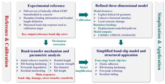
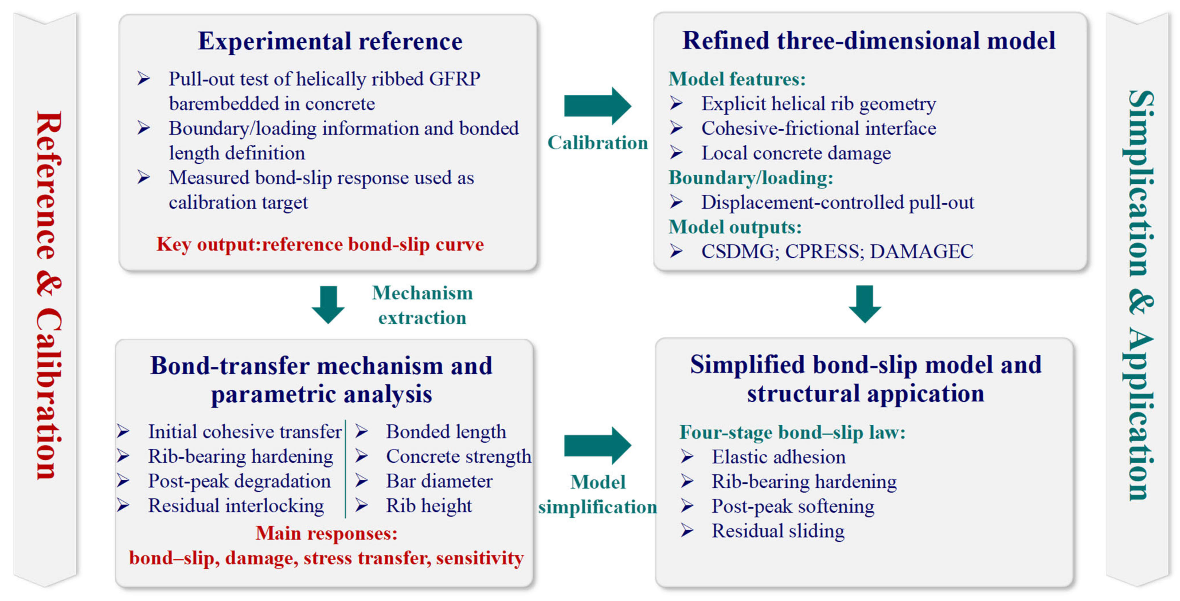
Accordingly, a 3D finite-element model was established for helically ribbed GFRP bars embedded in concrete, incorporating explicit rib geometry, cohesive-frictional contact, and concrete damaged plasticity. Following validation against independent experimental datasets, the model was applied to evaluate progressive stress transfer along the bonded interface. Finally, a simplified four-stage bond-slip model is proposed to enable structural-scale numerical analysis while retaining the physical characteristics of the 3D local response. The overall numerical framework of this study is illustrated in Figure 1.
Figure 1.
Numerical framework for bond-slip analysis and simplified modeling of helically ribbed GFRP bars in concrete.
2. Refined Three-Dimensional Numerical Model
The refined model was established to distinguish the principal mechanisms contributing to the bond response rather than representing them through a prescribed average bond-slip relationship. The considered mechanisms included initial cohesive adhesion, progressive interface degradation, normal rib-bearing contact, interface separation and re-contact, post-debonding frictional sliding, local concrete cracking and crushing, and non-uniform stress transfer along the bonded length. The numerical treatment of these mechanisms is described below, followed by validation against the reference pull-out tests.
2.1. Pull-Out Specimen and Refined Finite-Element Model
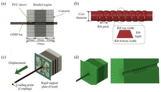
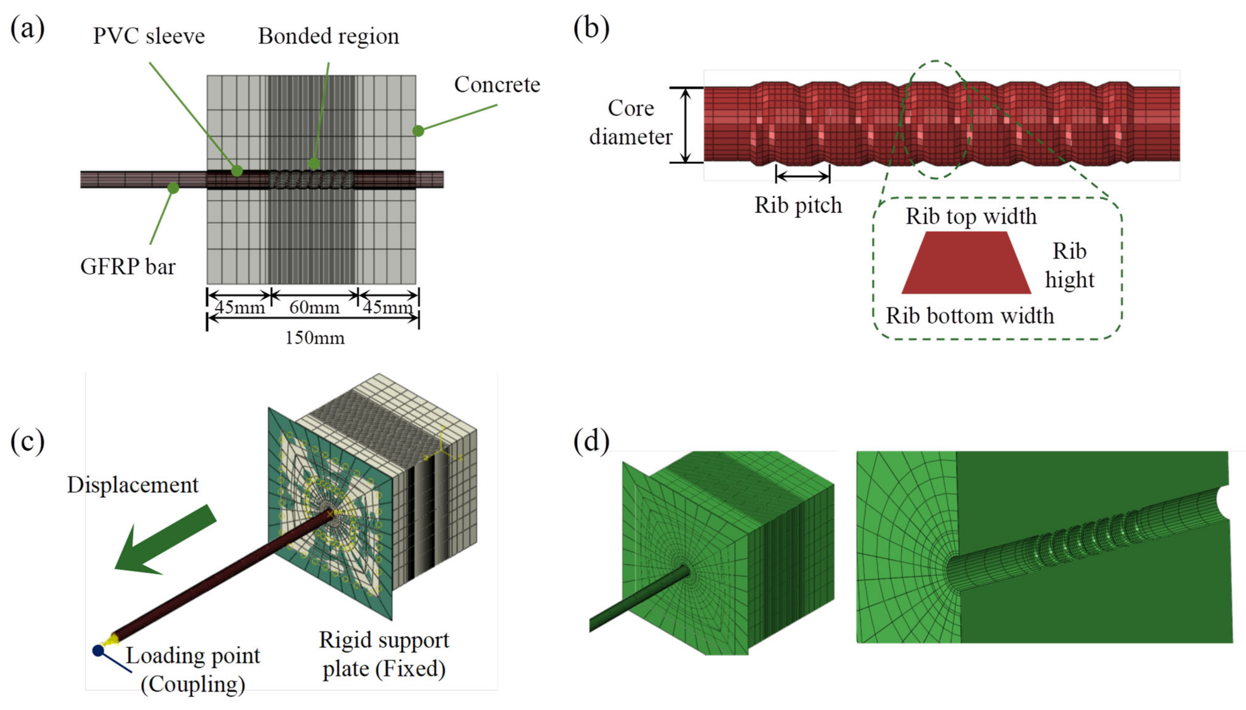
The refined three-dimensional finite-element model was established with reference to the pull-out tests reported by Tian [30]. As shown in Figure 2a, a helically ribbed GFRP bar was centrally embedded in a 150 mm concrete cube. The effective bonded length was 60 mm, while PVC sleeves were arranged on both sides to prevent unintended bond transfer outside the prescribed region. The main geometric parameters are summarized in Table 1.
Figure 2.
Geometry, boundary conditions, and discretization of the refined pull-out model: (a) Pull-out specimen and geometric dimensions, (b) Explicit helical-rib geometry, (c) Boundary and loading conditions, and (d) Mesh discretization and local refinement.
Table 1.
Geometric parameters of the baseline pull-out model.
The GFRP bar was modeled with an explicit single-start helical rib rather than an equivalent smooth cylindrical surface. As illustrated in Figure 2b, the bar had a core diameter of 12.0 mm, an outer diameter of 13.6 mm, a rib pitch of 8.0 mm, and a rib height of 0.8 mm. The concrete surface surrounding the bonded segment was generated with a matching threaded profile, allowing rib bearing, interface separation, and local concrete damage to develop directly during pull-out.
The loading and support conditions are shown in Figure 2c. The pull-out displacement was applied through a reference point coupled to the loaded end of the bar, and the concrete reaction was provided by a rigid support plate. As shown in Figure 2d, the mesh was locally refined around the ribs and the surrounding concrete grooves, while a coarser mesh was adopted away from the bonded region to reduce computational cost.
2.2. Material Models, Interface Interaction, and Boundary Conditions
Concrete was modeled using the concrete damaged plasticity model to account for rib-induced compression, plastic deformation, tensile cracking, and stiffness degradation. Compressive and tensile damage variables were used to evaluate the local deterioration around the threaded concrete duct. Concrete damage was represented through constitutive stiffness degradation, while explicit material removal through element deletion was not activated. The GFRP bar and PVC sleeves were modeled as linear-elastic solids because bar rupture and sleeve failure were not the governing failure modes in the reference tests. The principal material parameters are listed in Table 2.
Table 2.
Material and interface parameters used in the baseline model.
The bonded interface was defined as a surface-to-surface contact pair between the explicit helical surface of the GFRP bar and the matching concrete thread. Initial adhesion was represented using an uncoupled cohesive traction-separation law. Damage initiation was governed by a quadratic nominal-stress criterion, and the cohesive traction was progressively degraded using a linear displacement-based damage-evolution law with a failure separation of 2.0 mm. Accordingly, interface debonding developed progressively rather than being imposed at a prescribed slip.
Normal interaction was described by hard contact, which prevented penetration while allowing local separation and subsequent re-contact. Mechanical interlocking was generated directly by normal contact on the inclined helical-rib surface. Tangential sliding after local debonding was represented using a Coulomb penalty-friction law with a calibrated coefficient of μ = 0.03. Therefore, the residual resistance was jointly produced by friction and remaining rib-bearing contact rather than by an artificially prescribed residual bond stress.
The GFRP bar, concrete, and PVC sleeves were mainly discretized using C3D8R solid elements, with local C3D6 elements used near geometric transitions. The helical interface and surrounding concrete were locally refined to resolve the contact-pressure and damage gradients, while the far-field concrete was meshed more coarsely. The analysis was performed in Abaqus/Standard (Version 2021) using a displacement-controlled static implicit step with geometric nonlinearity enabled. Automatic stabilization was monitored through the artificial-to-internal energy ratio to ensure that the calculated response was not governed by numerical damping.
As shown in Figure 2c, the pull-out displacement was applied in the (+z) direction through a reference point coupled to the loaded end of the GFRP bar. The rigid support plate restrained the concrete reaction surface, while the remaining specimen surfaces were left unconstrained. The PVC-covered regions were excluded from bond transfer, ensuring that the measured response was governed by the central bonded segment.
2.3. Model Calibration and Numerical Reliability
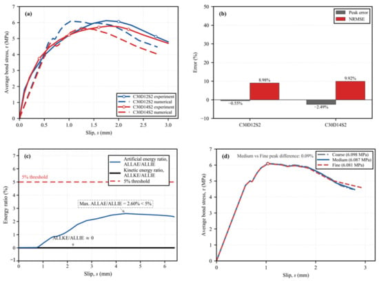
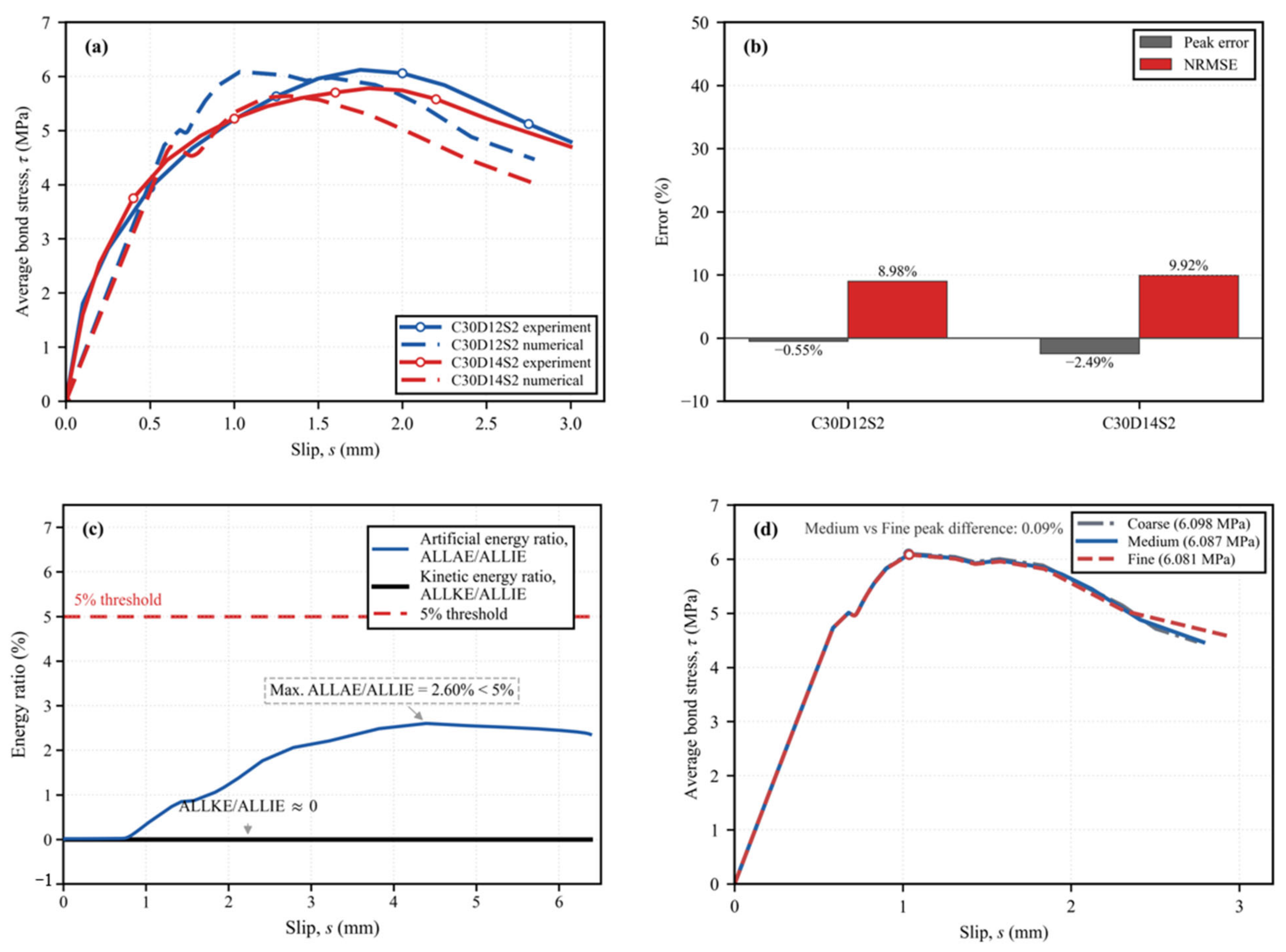
The interface parameters were calibrated against the bond-slip curve of the reference C30D12S2 and C30D14S2 pull-out specimens [30]. As illustrated in Figure 3a, the numerical model reproduces the initial ascending branch, peak resistance, and post-peak softening behavior of both specimens with reasonable accuracy. Quantitative error assessments are summarized in Figure 3b. For C30D12S2, the predicted peak bond stress is 6.087 MPa, which closely agrees with the experimental value of 6.120 MPa, representing an error of −0.55%, with a curve-level NRMSE of 8.98%. For C30D14S2, the predicted peak bond stress is 5.634 MPa, compared to the experimental result of 5.778 MPa, with an error of −2.49% and an NRMSE of 9.92%. Both error indices are below 10%, confirming the reliability of the model across different bar diameters without further parameter recalibration.
Figure 3.
Calibration of the refined model and assessment of numerical reliability: (a) Experimental [30] and numerical bond-slip responses, (b) Quantitative error assessment, (c) Energy-based quasi-static verification, and (d) mesh-sensitivity assessment.
The higher residual resistance predicted by the model was mainly attributed to the idealized rib geometry, constant friction coefficient, and absence of rib wear or concrete-element removal. Therefore, the calibrated model was considered suitable for evaluating the peak response, damage evolution, and relative effects of the investigated parameters, while the large-slip residual response was interpreted comparatively rather than as a direct design value.
Numerical reliability was further assessed through energy-ratio checks, as summarized in Figure 3c. During loading, the maximum artificial-to-internal energy ratio (ALLAE/ALLIE) remained approximately 2.60%, below the adopted 5% limit, while the kinetic-to-internal energy ratio (ALLKE/ALLIE) remained negligible. These results confirmed that the response was not governed by artificial energy stabilization or inertial effects.
The explicit representation of the helical rib and matching concrete profile allows normal bearing, interface separation, and local stress redistribution to develop directly during pull-out. Compared with models based on an equivalent smooth bar or a prescribed one-dimensional bond-slip law, this approach distinguishes the contributions of cohesive adhesion, frictional sliding, and mechanical interlocking, while concrete cracking and crushing are represented through stiffness degradation within the concrete damaged plasticity framework. The close agreement in the ascending and peak regions suggests that these modeling features provide a reliable representation of the principal bond-transfer mechanisms and peak resistance. Nevertheless, several idealizations should be considered when interpreting the post-peak response. While the principal rib geometry is retained, rib filets, manufacturing irregularities, and surface roughness are simplified, which may produce more regular contact and periodic rib re-engagement than in physical specimens. Moreover, the calibrated friction coefficient of μ = 0.03 is assumed to remain constant, whereas the actual frictional resistance may evolve with slip and surface abrasion. Additionally, because element deletion and progressive rib wear are not modeled, damaged concrete continues to participate in compressive contact, potentially preserving more residual resistance at large slips. Consequently, these assumptions primarily affect the post-peak fluctuations, which are intended to interpret frictional sliding and rib re-engagement, whereas the large-slip residual resistance should be applied with caution in direct design capacity evaluations.
A mesh sensitivity analysis was performed on the baseline C30D12S2 specimen by varying the number of radial concrete layers in the near-interface region, yielding coarse, medium, and fine models with 23,112, 24,840, and 26,568 solid elements, respectively. As shown in Figure 3d, the calculated bond-slip curves are nearly coincident over the slip range of 0.0 to 3.0 mm. The peak bond stresses obtained from the coarse, medium, and fine meshes are 6.098, 6.087, and 6.081 MPa, respectively, with corresponding peak slips of 1.034, 1.036, and 1.037 mm. The peak bond stress and peak slip differences between the medium and fine meshes are only 0.09% and 0.07%, respectively, while the curve-level normalized root-mean-square difference is 1.16%. Consequently, further mesh refinement yields negligible variations in the global bond response, and the medium mesh was adopted for subsequent analyses to optimize computational efficiency and numerical accuracy.
3. Bond-Slip Response and Load-Transfer Mechanism
The validated model was used to examine the evolution of the bond response from the local rib-concrete interface to the overall pull-out behavior. Representative loading states were selected from the bond-slip curve to relate the macroscopic response to interfacial damage, rib-bearing contact, and stress redistribution along the bonded length.
3.1. Characteristic Stages of the Bond-Slip Response
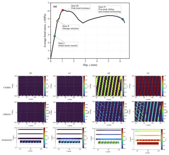
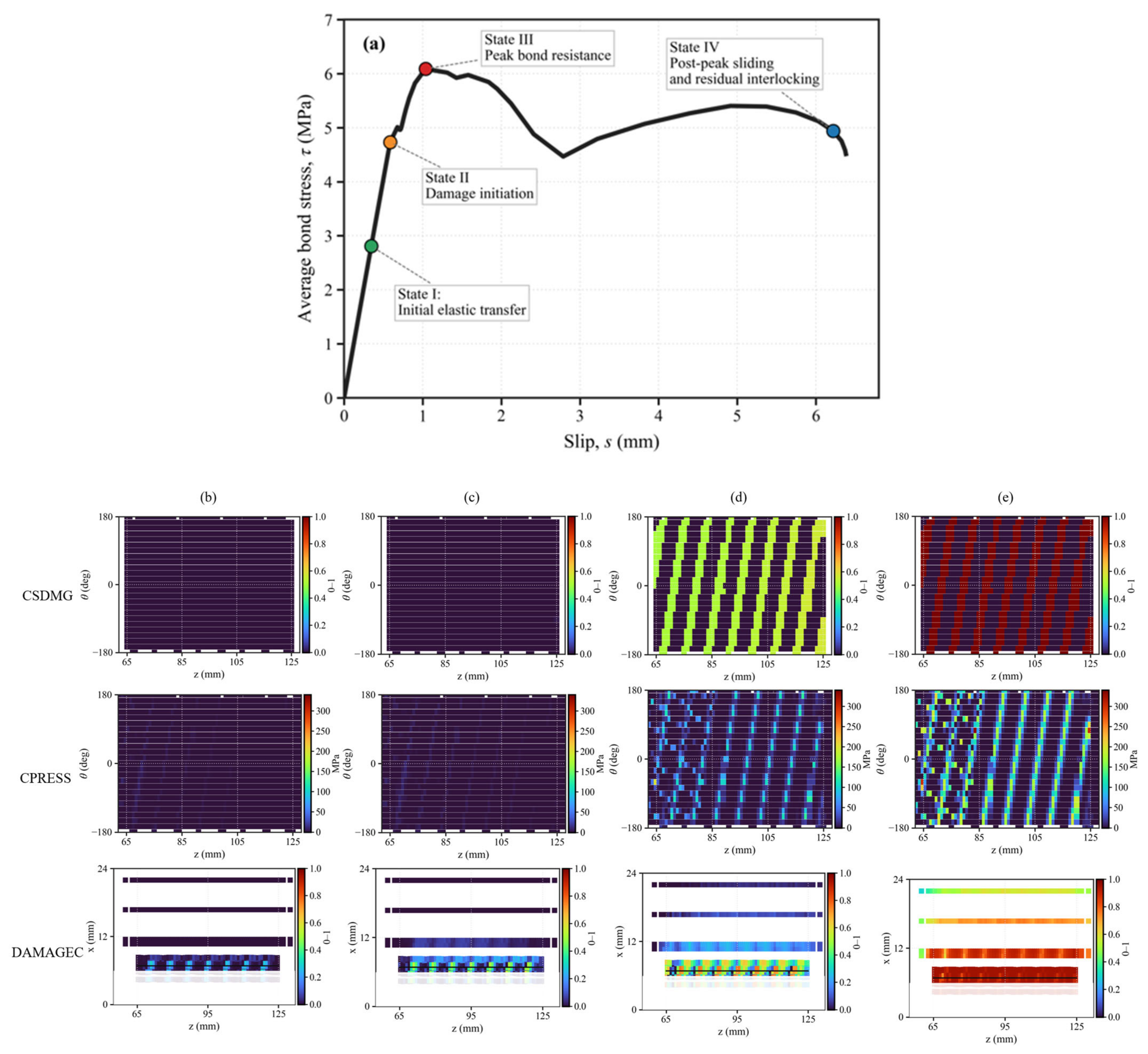
As shown in Figure 4a, four representative states were selected from the numerical bond-slip curve, corresponding to slips of 0.345, 0.585, 1.036, and 6.221 mm for States I to IV, respectively. To visualize the spatial evolution of the local bond mechanism, the cohesive contact damage, namely CSDMG, and contact pressure, namely CPRESS, were extracted from the contact fields and unfolded into z-theta interface maps, whereas concrete compressive damage, namely DAMAGEC, was plotted on a near-interface concrete half-section in the z-x coordinate system.
Figure 4.
Evolution of interfacial damage, rib-bearing contact, and concrete damage during pull-out: (a) bond-slip response and characteristic states, (b) state I: initial elastic transfer, (c) state II: damage initiation, (d) state III: peak bond resistance, and (e) state IV: post-peak sliding and residual interlocking.
These states were established using distinct physical criteria derived from these local variables. State I corresponds to the initial elastic transfer stage, where the cohesive interface remains fully intact, and contact damage is zero along the entire embedded length. State II corresponds to damage initiation, where cohesive damage starts to develop near the loaded end, and contact pressure begins to concentrate at the rib fronts, marking the transition from adhesion to rib-bearing action. At State III, the average bond stress reaches its peak as cohesive damage has spread extensively and concrete compressive damage at the rib fronts is fully mobilized, yielding the maximum combined resistance.
After the peak, progressive interface degradation and local concrete damage reduce the effective load-transfer capacity. State IV represents the post-peak sliding and residual interlocking stage, where the cohesive bond is completely degraded, and the interface resistance is sustained solely by Coulomb friction and mechanical rib re-engagement. These four states represent internal mechanical transitions that are difficult to isolate from the macro-level experimental curve alone, providing the basis for interpreting the local damage fields in Section 3.2.
3.2. Interfacial Damage and Contact Evolution
Figure 4b–e shows the evolution of cohesive damage (CSDMG), contact pressure (CPRESS), and concrete compressive damage (DAMAGEC) at the four characteristic states. At State I, the cohesive interface remains intact, and the relatively low contact pressure indicates adhesion-dominated transfer. At State II, cohesive damage initiates near the loaded-end ribs, accompanied by increasing rib-front contact pressure and localized concrete damage.
At the peak state (State III), cohesive traction, rib-bearing contact, and mechanical interlocking act together, with the maximum contact pressure increasing to 200.33 MPa. At State IV, cohesive degradation is complete in the critical region, but the average bond stress remains 4.937 MPa, while the localized contact pressure reaches 331.21 MPa. The increase in local contact pressure despite the reduction in average bond stress reflects localization of the effective transfer region rather than recovery of the cohesive contribution. The residual resistance is therefore sustained primarily by frictional sliding and intermittent rib re-engagement.
3.3. Stress Transfer Along the Bonded Length
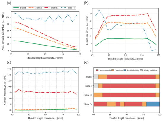
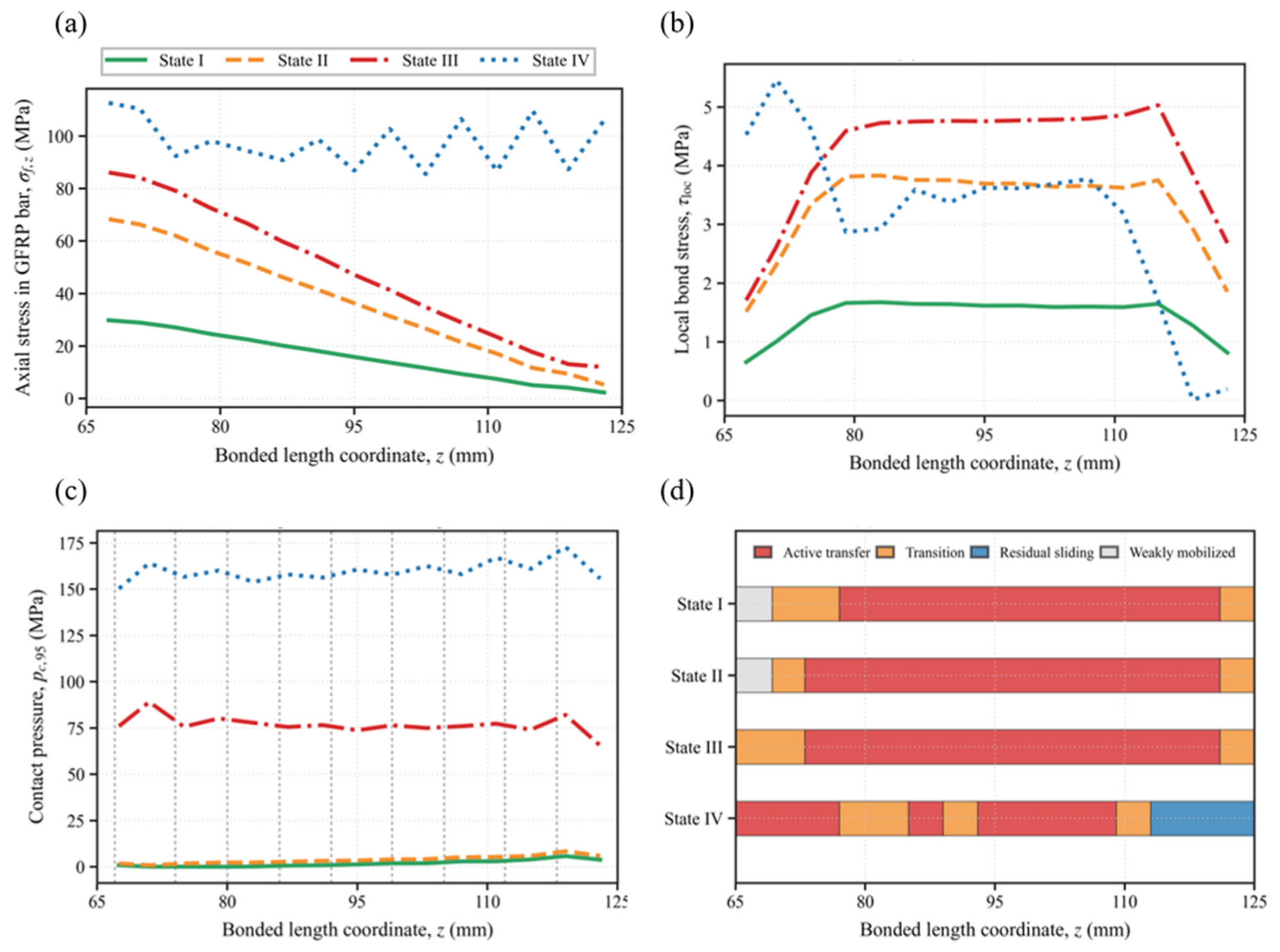
Figure 5a shows the axial stress distribution in the GFRP bar at the four characteristic states. Before the peak, the axial stress generally decreases from the loaded end toward the free end, confirming that the pull-out force is transferred progressively through the bonded interface rather than uniformly over the entire bonded length. As the applied load increases from State I to State III, the high-stress region extends over a larger portion of the bonded length. At State IV, the axial stress becomes more non-uniform because of local interface degradation and residual rib re-engagement, indicating a redistribution of the load-transfer path after peak resistance.
Figure 5.
Evolution of stress transfer along the bonded length: (a) axial stress in the GFRP bar, (b) local bond stress, (c) 95th-percentile contact pressure, and (d) effective stress-transfer zones.
The corresponding local bond-stress distributions are presented in Figure 5b. At States I and II, the local bond stress remains relatively low and is mainly mobilized near the loaded-end region. At State III, the local bond stress increases and becomes more widely distributed, indicating that a larger part of the bonded interface contributes to the peak resistance. After the peak, local degradation reduces the transfer efficiency near part of the loaded-end region, while residual stress transfer is maintained over the interior bonded length.
Figure 5c further shows the circumferential 95th-percentile contact pressure, pc,95, along the bonded length. Compared with the circumferential average value, pc,95 better captures the localized rib-bearing peaks. The high contact pressure at State IV indicates that localized rib contact remains active after cohesive degradation, even though the local bond-stress contribution has been reduced.
As shown in Figure 5d, the effective stress-transfer zones were classified using a normalized transfer index, defined as 0.75 times the normalized local bond stress plus 0.25 times the normalized CPRESS. Regions with a transfer index not lower than 0.70 were defined as active transfer zones, those between 0.40 and 0.70 as transition zones, and those lower than 0.40 as weakly mobilized zones. For State IV, regions with low local bond stress but high CPRESS were further identified as residual sliding zones. This classification shows that the bonded interface does not fail simultaneously; instead, local degradation and rib-contact re-engagement lead to progressive stress redistribution along the bonded length.
4. Parametric Analysis
The validated model was used to investigate the effects of bonded length, concrete strength, bar diameter, and rib height on the bond-slip response. A single-factor analysis was adopted, in which only the investigated parameter was varied while the remaining material, interface, and numerical settings were kept unchanged.
4.1. Analysis Cases and Evaluation Indices
The parameter levels are summarized in Table 3. The baseline model had a bonded length of 5d, a concrete strength grade of C30, a bar diameter of 12 mm, and a rib height of 0.8 mm.
Table 3.
Parameters considered in the numerical analysis.
The responses were evaluated using the peak bond stress (), peak slip (sp), initial stiffness (K0), residual bond stress () at a slip of 4.0 mm, and the work index (W0-4.75). The peak pull-out force (Pmax) was also considered when assessing bonded-length and diameter effects, because an increase in total capacity does not necessarily indicate improved nominal bond efficiency.
4.2. Effects of Key Parameters
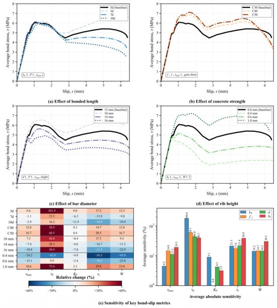
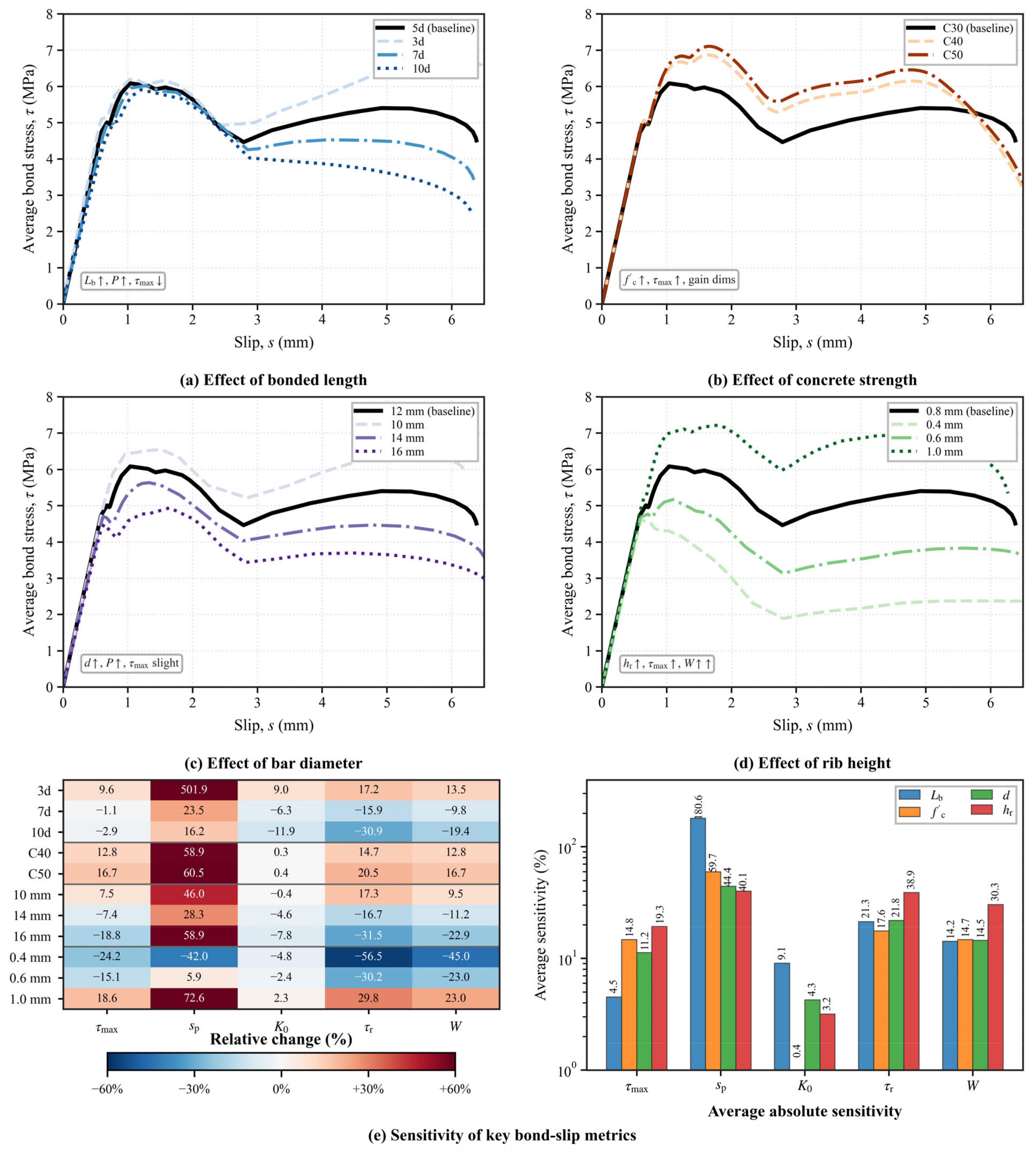
As shown in Figure 6a, the bonded length mainly affected the post-peak response and the utilization efficiency of the bonded interface. Although a longer bonded length can increase the total pull-out capacity, the average bond-stress response did not increase proportionally. Compared with the baseline case, the longer bonded lengths showed reduced residual resistance and work index, indicating that the additional interface was not fully mobilized because of non-uniform stress transfer and shear-lag effects.
Figure 6.
Parametric effects on the bond-slip response and sensitivity of key metrics: (a) bonded length; (b) concrete compressive strength, (c) bar diameter, (d) rib height, and (e) relative changes and average absolute sensitivities of key bond-slip metrics with respect to the baseline case. The upward (↑) and downward (↓) arrows represent increase and decrease, respectively.
Figure 6b shows that increasing the concrete strength enhanced the bond resistance, especially the peak and residual responses. The C40 and C50 cases exhibited higher bond stress than the C30 baseline, confirming that stronger concrete improved the local bearing resistance around the rib fronts. However, the improvement became less pronounced at higher strength levels, suggesting that the benefit of increasing concrete strength gradually diminished once rib-bearing resistance was sufficiently developed.
The effect of bar diameter is presented in Figure 6c. Increasing the bar diameter enlarged the bonded area and increased the total pull-out force, but the average bond stress did not increase accordingly. Compared with the 12 mm baseline case, larger diameters showed lower nominal bond efficiency, which can be attributed to stronger shear-lag effects and incomplete mobilization of the enlarged interface. Therefore, bar diameter mainly influenced the global pull-out capacity rather than directly improving the average bond strength.
As shown in Figure 6d, rib height had a direct influence on the mechanical interlocking effect. Increasing the rib height enhanced the peak resistance, residual bond stress, and energy dissipation, whereas smaller rib heights weakened the post-peak resistance. This indicates that rib geometry is a key factor controlling residual interlocking after cohesive degradation. Nevertheless, excessive rib height may also intensify local contact pressure and concrete damage near the rib fronts.
4.3. Sensitivity of Key Bond-Slip Metrics
The sensitivity results are summarized in Figure 6e, where the heatmap shows the relative changes in key bond-slip metrics and the bar chart gives the corresponding average absolute sensitivities. Bonded length exhibited the strongest influence on the slip at peak and also affected the initial stiffness, reflecting the role of anchorage length in controlling the development range of stress transfer. However, its effect on improving nominal bond efficiency was limited because the bonded interface was not uniformly mobilized.
Rib height showed the most significant influence on residual bond stress and work index, confirming that post-peak resistance and energy dissipation were mainly governed by rib-bearing contact and mechanical interlocking. Concrete strength had a moderate positive effect on peak and residual resistance, but its influence was smaller than that of rib height once the concrete surrounding the ribs had sufficient local bearing capacity. Bar diameter showed a clear size effect: larger diameters increased the available contact area and pull-out force but reduced the average bond efficiency.
Overall, Figure 6 indicates that different parameters control different aspects of the bond-slip response. Bonded length and bar diameter mainly affect global force transfer and bonded-area utilization, whereas concrete strength and especially rib height more directly govern local bearing, residual interlocking, and energy dissipation.
5. Simplified Bond-Slip Model
To facilitate structural-scale analysis, the refined three-dimensional response was reduced to a one-dimensional bond-slip relationship. The simplified model preserves the main characteristics of the numerical response while avoiding the explicit representation of the helical ribs and local contact fields.
5.1. Model Formulation and Parameter Determination
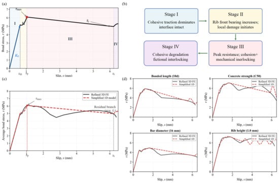
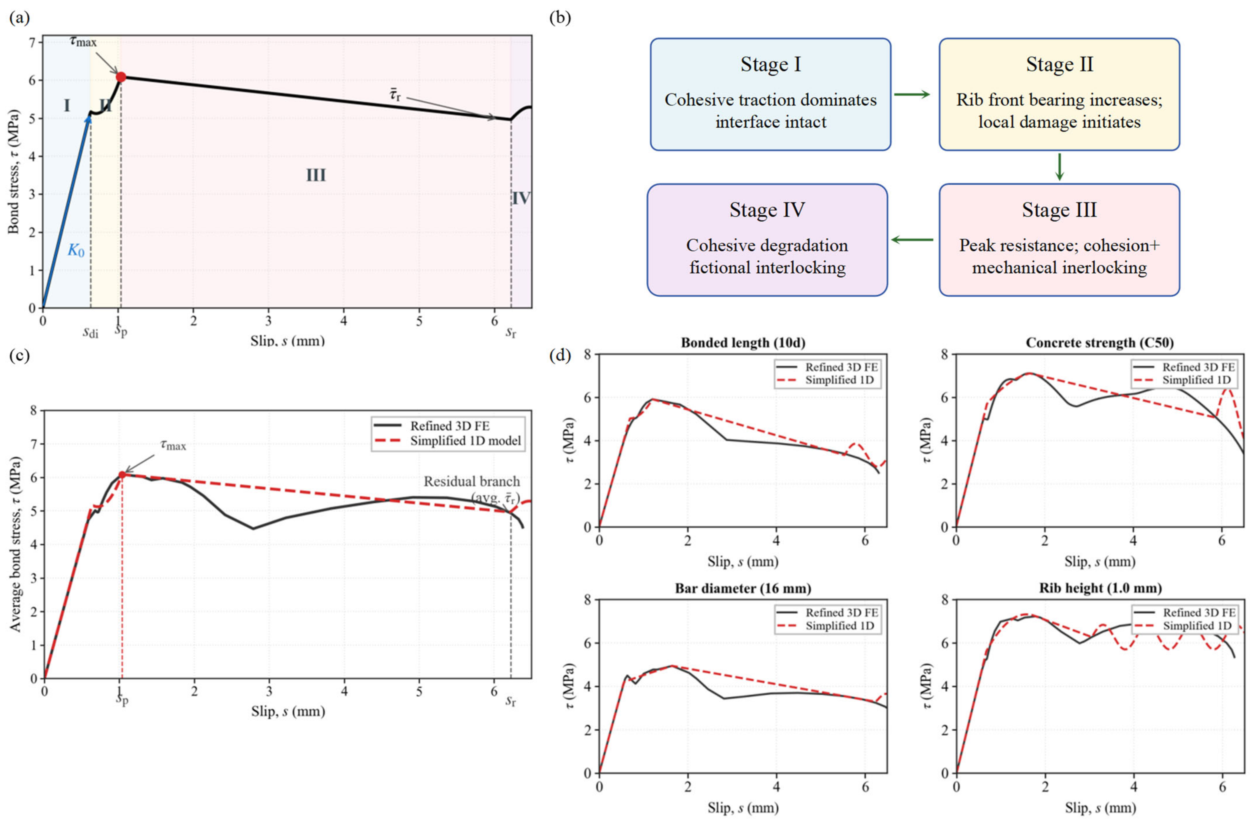
As shown in Figure 7a, the bond-slip response was divided into four stages: elastic adhesion, rib-bearing hardening, post-peak softening, and residual sliding. The equivalent relationship is expressed as:
where , and denote the damage-initiation, peak, and residual-transition slips, respectively; and are the peak and mean residual bond stresses. The initial coefficient is determined from the elastic stiffness, whereas – are obtained by satisfying continuity at and the peak condition at . The post-peak slope is calculated from the decrease between the peak and residual-transition points.
Figure 7.
Simplified one-dimensional bond-slip model and its validation: (a) four-stage bond-slip relationship, (b) physical interpretation of the four stages, (c) validation for the baseline specimen, and (d) validation under different parameter conditions.
The sinusoidal term represents the periodic re-engagement of the helical ribs during large-slip sliding. Its wavelength is related to the rib pitch, while the amplitude and phase control the residual fluctuation. When only the mean residual resistance is required, the fluctuation amplitude can be set to zero. As illustrated in Figure 7b, the four stages correspond physically to elastic adhesion, rib-bearing hardening, post-peak softening, and residual frictional interlocking. Therefore, the simplified relationship retains the main bond-transfer mechanisms identified from the refined model while avoiding explicit discretization of the helical ribs.
5.2. Model Validation and Applicability
The simplified model was first evaluated using the baseline specimen. As shown in Figure 7c, the simplified one-dimensional relationship reproduced the main characteristics of the refined three-dimensional response, including the initial stiffness, peak bond stress, post-peak softening trend, and mean residual resistance. This close agreement suggests that the proposed four-stage formulation effectively captures the macro-level bond-slip performance without requiring the explicit resolution of local rib geometries and contact stress fields. By simplifying these detailed localized stress states into a unified mathematical framework, the computational requirements are significantly reduced, enabling the modeling of larger structural components.
The transferability of the model was further examined using representative variations in bonded length, concrete strength, bar diameter, and rib height. Figure 7d shows that the simplified model successfully captured the major changes in peak resistance, softening behavior, and residual response under different parameter conditions. Although small local fluctuations caused by progressive rib re-engagement in the refined curves were not fully reproduced, the simplified model provided an adequate envelope and highly stable mean-response approximation for structural-scale simulations. This capability is particularly important for parametric structural design, where simulating the full three-dimensional rib interaction for multiple configurations remains computationally prohibitive.
The proposed relationship is therefore suitable for connector or zero-thickness interface elements where the global bond-slip response is required. In practical finite-element modeling, this relationship can be implemented directly into commercial software to represent the interface between reinforced polymer bars and concrete, substantially reducing the degrees of freedom in structural-scale models. However, the current application of this simplified formulation is limited to monotonic pull-out loading within the investigated parameter ranges. Additional calibration and experimental verification are required to extend the model parameters to cyclic loading conditions, environmental degradation, severe rib wear, or failure modes involving concrete splitting and bar rupture.
6. Conclusions
A refined three-dimensional finite-element model was developed to investigate the local interface interactions and progressive stress transfer of helically ribbed GFRP bars embedded in concrete. Based on the quantitative evaluations and parametric sensitivity analysis, the following primary conclusions are obtained:
- (1)
- The developed model successfully predicts the peak bond stress with a minor error of −0.55% for the 12 mm rebar and −2.49% for the 14 mm rebar. Furthermore, the analysis reveals that the post-peak fluctuations on the average bond-slip curves are governed by the periodic re-engagement of helical ribs, which arises from the numerical assumption of idealized geometry, explaining why these fluctuations are smoothed out in physical tests due to actual rib wear and concrete key shearing.
- (2)
- The stress-transfer along the bonded interface is highly non-uniform, characterized by the progressive migration of the active stress-transfer zone. Quantitative tracking using the normalized transfer index demonstrates that, during progressive debonding, the active transfer zone systematically migrates away from the loaded end toward the interior, explaining the structural shear-lag effect and the non-linear reduction in average bond strength for longer anchorage lengths.
- (3)
- The parametric sensitivity analysis establishes a clear hierarchical influence of design parameters. Rib height has the most significant influence on residual resistance and energy dissipation, whereas increasing concrete strength exhibits diminishing marginal benefits once the local compressive bearing capacity around the rib fronts is fully developed, and increasing the bar diameter primarily scales the total pull-out force but reduces the nominal bond efficiency.
- (4)
- The proposed simplified four-stage bond-slip relationship successfully replicates the initial stiffness, peak resistance, post-peak softening, and mean residual response. Every stage of this simplified model physically aligns with a distinct interface degradation phase, namely elastic adhesion, rib-bearing hardening, post-peak softening, and residual sliding, offering a computationally efficient macro-element formulation for structural-scale simulations.
Author Contributions
Conceptualization, S.P.; methodology, Y.J. and S.P.; software, Y.J.; validation, S.P.; formal analysis, Y.J.; investigation, S.H.; resources, S.H.; data curation, S.H.; writing—original draft preparation, Y.J. and S.P.; writing—review and editing, S.P., S.H., and R.F.; visualization, Y.J.; supervision, R.F.; project administration, R.F.; funding acquisition, R.F. All authors have read and agreed to the published version of the manuscript.
Funding
This study was supported by the project “Key Technologies for Foundation Design and Construction of Flexible Anti-Eddy-Current Fiber-Reinforced Composite Bars for Reactors”, which belongs to the Science and Technology Project of State Grid Jiangsu Electric Power Co., Ltd., with Project No. J2025194.
Data Availability Statement
Data will be made available on request.
Conflicts of Interest
Author Shijun Huang was employed by State Grid Jiangsu Electric Power Co., Ltd. The remaining authors declare that the research was conducted in the absence of any commercial or financial relationships that could be construed as a potential conflict of interest. The authors declare that this study received funding from State Grid Jiangsu Electric Power Co., Ltd. (Project No. J2025194). The funder had the following involvement with the study: resources, data curation, as well as writing—review and editing of the manuscript.
References
- Faqih, F.; Zayed, T.; Soliman, E. Factors and defects analysis of physical and environmental condition of buildings. J. Build. Pathol. Rehabil. 2020, 5, 19. [Google Scholar] [CrossRef] [Scilit]
- Koch, G.; Brongers, M.; Thompson, N.; Virmani, Y.P.; Payer, J. Corrosion Cost and Preventive Strategies in the United States; Federal Highway Administration: Washington, DC, USA, 2002; Available online: https://www.semanticscholar.org/paper/CORROSION-COST-AND-PREVENTIVE-STRATEGIES-IN-THE-Koch-Brongers/791f2d6f7ee809657f38ab843fd00dd9db34edad (accessed on 14 June 2026).
- Kakooei, S.; Akil, H.M.; Dolati, A.; Rouhi, J. The corrosion investigation of rebar embedded in the fibers reinforced concrete. Constr. Build. Mater. 2012, 35, 564–570. [Google Scholar] [CrossRef] [Scilit]
- Abbood, I.S.; Odaa, S.A.; Hasan, K.F.; Jasim, M.A. Properties evaluation of fiber reinforced polymers and their constituent materials used in structures—A review. Mater. Today Proc. 2021, 43, 1003–1008. [Google Scholar] [CrossRef] [Scilit]
- Hu, X.; Xiao, J.; Zhang, K.; Zhang, Q. The state-of-the-art study on durability of FRP reinforced concrete with seawater and sea sand. J. Build. Eng. 2022, 51, 104294. [Google Scholar] [CrossRef] [Scilit]
- Yan, F.; Lin, Z.B.; Yang, M.J. Bond mechanism and bond strength of GFRP bars to concrete: A review. Compos. Part B 2016, 98, 56–69. [Google Scholar] [CrossRef] [Scilit]
- Solyom, S.; Balazs, G.L. Bond of FRP bars with different surface characteristics. Constr. Build. Mater. 2020, 264, 119839. [Google Scholar] [CrossRef] [Scilit]
- Shan, Z.; Liang, K.; Chen, L. Bond behavior of helically wound FRP bars with different surface characteristics in fiber-reinforced concrete. J. Build. Eng. 2023, 65, 105504. [Google Scholar] [CrossRef] [Scilit]
- El-Nemr, A.M.; Ahmed, E.A.; Barris, C.; Joyklad, P.; Hussain, Q.; Benmokrane, B. Bond performance of fiber reinforced polymer bars in normal- and high-strength concrete. Constr. Build. Mater. 2023, 393, 131957. [Google Scholar] [CrossRef] [Scilit]
- Romanazzi, V.; Leone, M.; Aiello, M.A.; Pecce, M.R. Bonding behavior of geopolymer concrete with steel and GFRP bars. Compos. Struct. 2022, 300, 116150. [Google Scholar] [CrossRef] [Scilit]
- Hao, Q.; Wang, Y.; He, Z.; Ou, J. Bond strength of glass fiber reinforced polymer ribbed rebars in normal strength concrete. Constr. Build. Mater. 2009, 23, 865–871. [Google Scholar] [CrossRef] [Scilit]
- Ke, L.; Ma, K.; Chen, Z.; Li, Y.; Chen, G.; Feng, Z. Bond-slip and bond strength models for FRP bars embedded in ultra-high-performance concrete: A critical review. Structures 2024, 64, 106551. [Google Scholar] [CrossRef] [Scilit]
- Yin, S.; Hu, C.; Liang, X. Bonding properties of different kinds of FRP bars and steel bars with all-coral aggregate seawater concrete. J. Mater. Civ. Eng. 2020, 32, 04020282. [Google Scholar] [CrossRef] [Scilit]
- Zeng, J.-J.; Liao, J.; Zhuge, Y.; Guo, Y.-C.; Zhou, J.-K.; Huang, Z.-H.; Zhang, L. Bond behavior between GFRP bars and seawater sea-sand fiber-reinforced ultra-high strength concrete. Eng. Struct. 2022, 254, 113787. [Google Scholar] [CrossRef] [Scilit]
- Zeng, J.-J.; Sun, H.-Q.; Deng, R.-B.; Yan, Z.-T.; Zhuge, Y. Bond performance between FRP bars and 3D-printed high-performance concrete. Structures 2025, 73, 108377. [Google Scholar] [CrossRef] [Scilit]
- Malvar, L.J. Bond Stress-Slip Characteristics of FRP Rebars; Naval Facilities Engineering Service Center: Port Hueneme, CA, USA, 1994. [Google Scholar]
- Eligehausen, R.; Popov, E.P.; Bertero, V.V. Local Bond Stress-Slip Relationships of Deformed Bars Under Generalized Excitations: Experimental Results and Analytical Model; Earthquake Engineering Research Center, University of California: Berkeley, CA, USA, 1983. [Google Scholar]
- Rossetti, V.A.; Galeota, D.; Giammatteo, M.M. Local bond stress-slip relationships of glass fibre reinforced plastic bars embedded in concrete. Mater. Struct. 1995, 28, 340–344. [Google Scholar] [CrossRef] [Scilit]
- Cosenza, E.; Manfredi, G.; Realfonzo, R. Behavior and modeling of bond of FRP rebars to concrete. J. Compos. Constr. 1997, 1, 40–51. [Google Scholar] [CrossRef] [Scilit]
- Cosenza, E.; Manfredi, G.; Realfonzo, R. Analytical Modeling of Bond Between FRP Reinforcing Bars and Concrete; E & FN Spon: London, UK, 1995; pp. 164–179. [Google Scholar]
- Rolland, A. Analytical and numerical modeling of the bond behavior between FRP reinforcing bars and concrete. Constr. Build. Mater. 2020, 231, 117160. [Google Scholar] [CrossRef] [Scilit]
- Peng, S.; Feng, R.; Huang, S.; Cui, L. Physics-aware edge-centric graph neural networks for full-field mechanics simulation of reticulated shells. Eng. Struct. 2026, 360, 122759. [Google Scholar] [CrossRef] [Scilit]
- Wang, L.; Feng, R.; Du, H.; Liu, P.; Lv, H.; Huang, S.; Cui, L. Research and application of a novel rigid-flexible hybrid support system in large-span curtain walls. Structures 2026, 88, 111894. [Google Scholar] [CrossRef] [Scilit]
- Davalos, J.F. Numerical Modeling for the Interface Bond of Concrete and FRP Bar; American Society of Civil Engineers: Reston, VA, USA, 2008; p. 1. [Google Scholar]
- Zhang, R.B.; Jin, L.; Liu, M.J.; Du, X.L.; Liu, J.B. Refined modeling of the interfacial behavior between FRP bars and concrete under different loading rates. Compos. Struct. 2022, 291, 115676. [Google Scholar] [CrossRef] [Scilit]
- Jin, L.; Liu, M.J.; Zhang, R.B.; Du, X.L. 3D meso-scale modelling of the interface behavior between ribbed steel bar and concrete. Eng. Fract. Mech. 2020, 239, 107291. [Google Scholar] [CrossRef] [Scilit]
- Farooq, U.; Nakamura, H.; Miura, T.; Yamamoto, Y. Proposal of bond behavior simulation model by using discretized voronoi mesh for concrete and beam element for reinforcement. Cem. Concr. Compos. 2020, 110, 103593. [Google Scholar] [CrossRef] [Scilit]
- Farooq, U.; Nakamura, H.; Miura, T. Bond behavior evaluation of deformed rebar dependent on lateral pressure confinement including various structural parameters. Cem. Concr. Compos. 2021, 119, 103996. [Google Scholar] [CrossRef] [Scilit]
- Sarraz, A.; Nakamura, H.; Kanakubo, T.; Miura, T.; Kobayashi, H. Bond behavior simulation of deformed rebar in fiber-reinforced cementitious composites using three-dimensional meso-scale model. Cem. Concr. Compos. 2022, 131, 104589. [Google Scholar] [CrossRef] [Scilit]
- Tian, W.M. Research on the Flexural Performance of GFRP Bar Concrete Two-Way Slabs. Master’s Dissertation, Shaoxing University, Shaoxing, China, 2024. (In Chinese) [Google Scholar] [CrossRef]

Disclaimer/Publisher’s Note: The statements, opinions and data contained in all publications are solely those of the individual author(s) and contributor(s) and not of MDPI and/or the editor(s). MDPI and/or the editor(s) disclaim responsibility for any injury to people or property resulting from any ideas, methods, instructions or products referred to in the content. |
© 2026 by the authors. Licensee MDPI, Basel, Switzerland. This article is an open access article distributed under the terms and conditions of the Creative Commons Attribution (CC BY) license.