


Abstract
The huge demand for natural sand in the global construction industry has caused resource shortages and severe environmental issues. Meanwhile, China produces massive annual iron tailings, and their stockpiling poses prominent potential safety hazards. At present, numerous investigations have been carried out on the fundamental properties of concrete prepared by replacing natural sand with iron tailings sand (ITS). However, most studies are limited to single replacement ratios and conventional strength mix proportions. Systematic research focusing on high-replacement-ratio systems, long-term durability performance, and supporting practical construction technologies for engineering applications remains insufficient. Obvious gaps still exist regarding the key mechanisms and practical operation standards for high-value and large-scale utilization. Against this background, this paper prepares concrete with three strength grades (C30, C40, C50) and six ITS replacement ratios (0%, 20%, 40%, 60%, 80%, 100%). Cube compressive tests and prism axial compressive tests are conducted, combined with SEM microscopic microstructure analysis. Axial compression tests and bearing capacity research are further carried out on reinforced concrete short columns (RCSC) with the optimal replacement ratio. The results show that concrete compressive strength increases first and then decreases with the rise in iron tailings sand concrete (ITSC), with 60% identified as the optimal replacement ratio. At this ratio, the compressive strength of C30, C40 and C50 concrete increases by 24.3%, 11.5% and 12.9%, respectively, while the bearing capacity of short columns rises correspondingly by 18%, 14.1% and 8.1%. Microscopic test results reveal that ITS exerts both physical filling and chemical active effects. Its fine particles fill internal pores inside the matrix and refine the pore structure. Meanwhile, the reactive mineral components contained in ITS can participate in the hydration reaction of the cementitious system, accelerate the hydration rate and generate more dense hydration products. Therefore, ITS facilitates the hydration process and improves the mechanical properties of concrete. A calculation method for the axial bearing capacity of RCSC incorporating ITS is proposed via theoretical analysis. This study provides a theoretical basis for preparing concrete by replacing natural sand with ITS. Using ITS as aggregate is expected to alleviate tailings stockpiling risks, reduce natural sand consumption, and realize solid waste resource recycling. It also offers valuable references for the green development of the construction industry and safety protection in mining areas.
1. Introduction
Iron tailings are the primary solid waste generated during the beneficiation of iron ore. In China, the annual discharge exceeds 600 million tons [1,2], the majority of which is stockpiled in tailings ponds. Iron tailings occupy land resources for a long time and pose potential safety hazards such as dam failure and soil and water pollution. Meanwhile, the demand for concrete aggregates in the construction industry continues to grow, with China’s annual consumption of natural sand and gravel exceeding 20 billion tons [3,4]. As non-renewable resources, natural aggregates—particularly river sand—are subject to overexploitation, which leads to river channel degradation, soil erosion, and a series of environmental problems, thereby posing severe challenges to their sustainable supply.
Against this backdrop, promoting the resource utilization of solid waste and alleviating the supply–demand imbalance in natural aggregates have become critical issues to be addressed in the field of civil engineering. The use of ITS as a partial or complete replacement for natural fine aggregates in concrete not only facilitates the large-scale consumption of tailings but also provides a viable pathway for the green transformation of concrete raw materials. Consequently, this approach has attracted extensive attention from researchers worldwide [5,6].
In terms of basic physical properties, ITS presents certain similarities to natural river sand in particle gradation and apparent density, which provides a fundamental prerequisite for its application as a fine aggregate to replace natural sand in concrete preparation [7,8]. However, ITS cannot simply equivalently replace natural sand. Due to the differences in surface roughness, fine powder content and mineral composition between ITS and natural river sand, the incorporation of ITS simultaneously affects the workability of fresh concrete, the mechanical properties of hardened concrete, durability, and the structure of the aggregate–paste interfacial transition zone. Therefore, when evaluating the performance of ITSC, it is necessary to not only verify whether the compressive strength meets the requirements, but also to comprehensively consider multiple factors including strength development law, durability and microscopic interfacial structure.
In terms of macroscopic mechanical properties, numerous studies have demonstrated that ITSC exhibits mechanical performance superior or comparable to river sand concrete, and can meet the requirements of engineering applications. Jian Zhang [9] compared C40 concrete prepared using well-graded ITS and river sand, and found that ITSC achieved higher strength: the 28 d and 90 d compressive strengths increased by 7.93% and 2.87%, respectively, while the splitting tensile strengths increased by 16.71% and 5.84%, respectively. Li et al. [10] prepared concrete with river sand, ITS, and mixed sand under identical conditions, and reported that the compressive strength of ITSC was 24.1% higher than that of the river sand group and 9.5% higher than that of the mixed sand group. Shettima et al. [11] adopted ITS replacement ratios ranging from 25% to 100%, and indicated that its compressive strength, splitting tensile strength and elastic modulus had no significant difference from those of ordinary concrete. Fang Y et al. [12] pointed out that the mechanical properties of ITSC generally reach or exceed those of natural river sand concrete at a replacement ratio of 25–50%. Yu F et al. [13] systematically investigated basic mechanical parameters including compressive strength, elastic modulus and peak strain, verifying that ultra-fine ITS can serve as an effective substitute for natural river sand. Zhigang Z et al. [14] explored the feasibility of utilizing ITS as fine aggregate to produce UHPC. To optimize the excellent performance of UHPC mortar, influencing factors such as sand type, sand blending ratio and maximum particle size of fine aggregate were studied. The test results indicate that the comprehensive performance of tailings sand is comparable to silica sand and superior to river sand. The above results indicate that ITSC with a reasonable mix proportion can meet the mechanical performance requirements for engineering applications.
From the perspective of different replacement levels, the replacement ratio significantly affects the mechanical properties of ITSC. Most studies show an overall trend of first increasing and then decreasing, with the optimal replacement ratio mainly concentrated in the range of 30–60% (Table 1). The influence of ITS on the workability of concrete shows an obvious dependence on replacement rate. A proper dosage of ITS can optimize the gradation of fine aggregates and the coating state of paste, and improve the uniformity of fresh mixtures. Nevertheless, an excessively high replacement rate will increase inter-particle friction and water demand of mixtures due to the angular particle shape, rough surface and high fines content of ITS. This consequently reduces fluidity, aggravates slump loss, and may even lead to bleeding and deteriorated mixture stability. Nan Li et al. [15] recommended fine aggregate replacement ratios of 20–40% and coarse aggregate replacement ratios of 30–60%, which can improve concrete compactness, interfacial transition zone performance, as well as impermeability, frost resistance and sulfate erosion resistance. Wang Yonggang et al. [16] verified that the compound incorporation of ITS and river sand can significantly enhance workability, mechanical properties and durability. A 40% replacement ratio achieves the optimal fluidity and paste coating performance, with controllable slump loss within 2 h, while an excessively high replacement ratio reduces fluidity and induces bleeding. Ning Baokuan et al. [17] conducted axial compression tests under replacement ratios ranging from 0% to 80%, and determined 60% as the optimal replacement ratio, at which the axial compression performance, stiffness and elastic modulus of concrete are improved most remarkably. Studies by Duan et al. [18], Ghannam et al. [19], Karthikeyan et al. [20], and Shettima et al. [11] consistently indicated that with the increase in ITS replacement ratio, the compressive strength and splitting tensile strength present a trend of first increasing and then decreasing, while the elastic modulus shows a continuous upward trend. A replacement ratio of 30–40% leads to mechanical properties slightly superior to those of ordinary concrete. Overall, existing studies have reached a general consensus. At low to medium replacement rates, ITS improves concrete compactness via particle filling, gradation optimization and interfacial modification, thereby enhancing mechanical properties. However, excessively high replacement rates degrade concrete workability. Adverse factors such as increased local pore defects and interfacial stress concentration may offset the strengthening effect.
Table 1.
Optimal Replacement Ratio and Mechanical Law.
At the microstructural level, relevant studies have elucidated the intrinsic mechanisms by which ITS influences concrete performance. Wang W et al. [21] revealed via qualitative XRD and SEM analyses that the moderate incorporation of iron tailing sand (IOTS) and iron tailing powder (IOTP) facilitated the formation of gel products and densified the interfacial transition zone (ITZ). Arbili et al. [22] employed scanning electron microscopy (SEM) and found that the active mineral components contained in ITS can promote cement hydration and improve the internal structure of concrete. Almada et al. [23] utilized multiple microstructural characterization techniques, including backscattered electron imaging (BSE), energy-dispersive spectroscopy (EDS) line scanning, and nanoindentation, and confirmed that the incorporation of ITS can significantly refine the interfacial transition zone (ITZ), enhance the hardness and indentation modulus of the specimens, and thereby improve the macroscopic mechanical properties. Liu J et al. [24] conducted microstructure analysis and found that unsintered artificial aggregate made from ITS significantly improves the ITZ between the UHPC matrix and aggregates. Notably, the width of the ITZ between the UHPC matrix and quartz sand reaches the minimum value at an artificial aggregate replacement ratio of 15%. Ma X et al. [25] verified via BSE-EDS and nanoindentation tests that ITS can effectively narrow the ITZ, optimize the interfacial micromechanical properties, and homogenize the compressive stress transfer inside components. They elucidated the internal mechanism by which ITS improves the bearing capacity of concrete short columns from a microscopic perspective. These findings provide a scientific explanation for the performance enhancement of ITSC from the perspectives of microstructure and the interfacial transition zone.
At present, extensive research has been conducted worldwide on the fundamental material properties of ITSC. Nevertheless, studies on the structural mechanical behavior and adapted calculation methods for core load-bearing components such as reinforced concrete columns remain incomplete, restricting the engineering popularization of this material. Li et al. [26] revealed the correlation between the strength and pore structure of ITSC via microscopic tests, yet their research only focused on the performance of material specimens without accounting for structural effects brought by reinforcement arrangement and stress states of components. Ma et al. [25] carried out mechanical tests on eccentric ITSC columns and verified the applicability of basic mechanical assumptions for such components, but failed to propose correction approaches for deviations in standard calculation results. Su et al. [27] investigated the compressive performance of ITSC columns under high temperatures, without optimizing design formulas for static bearing capacity at ambient temperature. In summary, existing studies mostly concentrate on material characterization or performance analysis under single working conditions. Traditional calculation formulas specified in current codes for ordinary concrete cannot accurately predict the bearing capacity of ITSC columns, leaving an obvious theoretical gap.
According to the above literature, using ITS as fine aggregate to replace natural sand in concrete has been proven to affect the macroscopic mechanical properties of concrete through particle filling, aggregate gradation improvement, paste compactness enhancement and optimization of the aggregate–paste interfacial transition zone (ITZ). Nevertheless, most existing studies evaluate material properties based on a single strength grade or limited mix proportions. Research on the application of ITS in the concrete of various strength grades remains insufficient, and there is still a lack of systematic understanding of whether the performance of ITS varies with concrete strength grades. Therefore, it is necessary to further reveal the coupling relationship between ITS content and the macroscopic mechanical properties of concrete across different strength grades.
Current research on ITSC mainly focuses on its material mechanical properties. Few investigations have addressed its application in reinforced concrete compression members and the synergistic interaction between ITSC, longitudinal rebars and transverse stirrups; the bearing capacity, deformation characteristics and failure modes of such members remain insufficiently understood. Accordingly, this study carries out systematic research from three perspectives: macroscopic material performance, microscopic microstructure and structural bearing behavior. Concrete specimens with three strength grades (C30, C40 and C50) are prepared with natural sand replaced equally by ITS at volume replacement ratios ranging from 0% to 100%. The effects of replacement content on cubic and axial compressive strengths are analyzed, with particular attention paid to how the optimal replacement ratio varies with matrix strength grade, so as to provide references for mixture proportion optimization under various design strengths. SEM is adopted to characterize the interfacial bonding condition and morphology of the ITZ between ITS and cement paste. The microscopic mechanisms underlying varying reinforcement efficiencies of ITS in matrices with different compactness are elaborated, and the applicable working conditions are clarified. Based on the above material test results, reinforced concrete short columns are fabricated using the optimal replacement ratio for each strength grade and subjected to axial compression tests. Their failure patterns, ultimate bearing capacity and deformation responses are analyzed to verify whether the superior mechanical performance at the material level can be retained in structural members. The synergistic mechanical behavior between concrete and steel reinforcements is evaluated, and the applicability of the existing standard calculation formulas for axial compression members to ITSC short columns is examined. This work provides experimental support for the practical engineering application of ITSC.
2. Materials and Experimental Program
2.1. Raw Materials
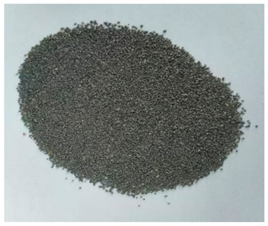
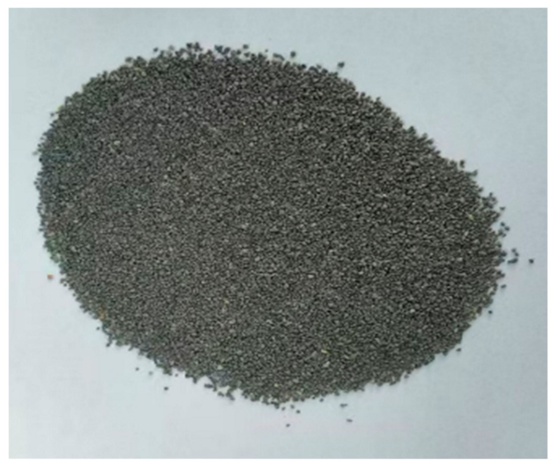
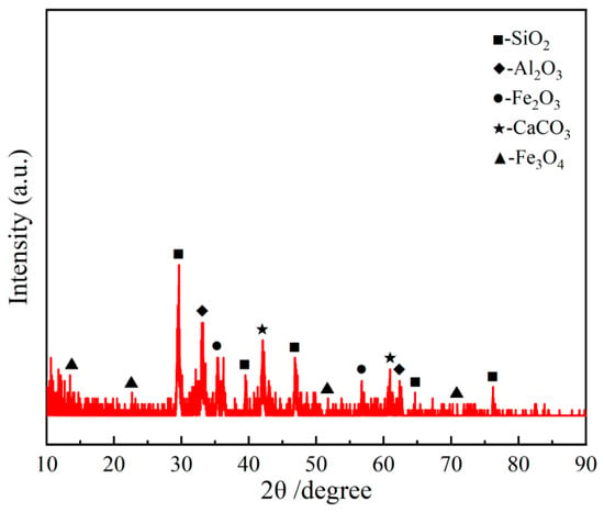
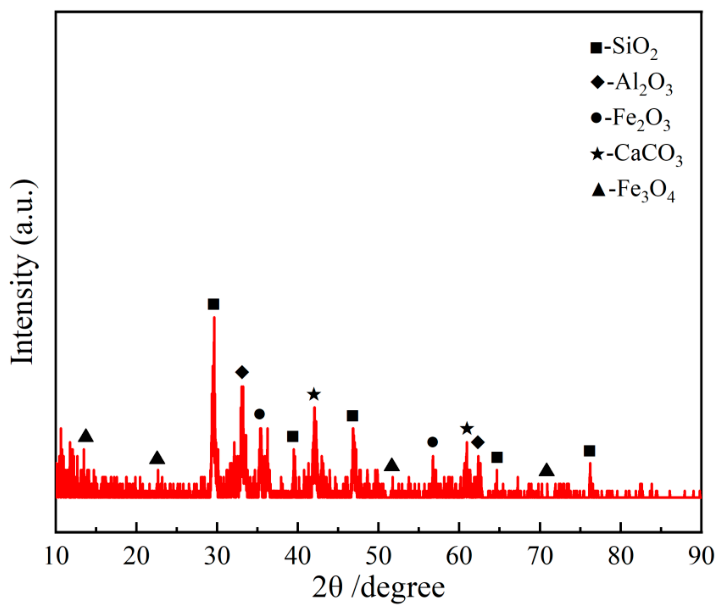
Ordinary Portland cement of Dinglu brand (Jilin Yatai Dinglu Cement Co., Ltd., Changchun, China) was adopted in this test. ITS was supplied by a local iron and steel enterprise, with particle sizes ranging from 0.5 mm to 4.75 mm, as illustrated in Figure 1. The chemical compositions of the above two raw materials are listed in Table 2, and their primary physical and mechanical properties are summarized in Table 3. Coarse and fine aggregates used in this test all meet the requirements of the national standard [28], and their main performance indices are listed in Table 3. For X-ray diffraction (XRD) analysis, a 33 mg sample of the ITS used in this study was ground to a powder with a particle size smaller than 200 mesh (0.2 mm). The resulting diffraction pattern is shown in Figure 2. The physical properties of the ITS are summarized in Table 3. A naphthalene-based high-efficiency water-reducing agent (FDN-C) was employed in the experiments, with a water-reduction rate of 18% and a dosage of 0.75% by mass of total cementitious materials. All performance parameters of the admixture conformed to the requirements of GB 8076-2008 [29]. The water absorption rate of iron ITS ranges from 4.0% to 8.0%, which is markedly higher than that of natural sand (1.0–3.0%). Such high water absorption can directly alter the effective water–cement ratio and workability of concrete. In this study, ITS was pretreated by oven-drying and sieving to stabilize its moisture content within a reasonable range, so as to eliminate fluctuations caused by variable water absorption. The water absorption of ITS was accounted for by adjusting the effective water dosage.
Figure 1.
Morphology of ITS.
Table 2.
Main chemical compositions of raw materials (mass fraction, %).
Table 3.
Main physical and mechanical properties of raw materials.
Figure 2.
XRD Pattern of ITS.
Figure 3 presents the SEM micromorphology of ITS. It can be observed that ITS particles feature a rough surface and distinct angularity with few internal pores, and a large number of irregular fine mineral components adhere to the particle surface. Combined with the chemical composition analysis, ITS is mainly composed of SiO2, Al2O3, and Fe2O3. Fe2O3 is not a typical pozzolanic component, yet it exhibits certain reactivity under the temperature-rise environment of cement hydration. It can participate in hydration reactions to form dense iron-based products and optimize the microscopic structure. The silico-aluminum active components can potentially take part in secondary hydration; the generated hydration products fill the gaps among aggregates and internal pores, densify the matrix structure, and improve the macroscopic mechanical properties of concrete. When the ITS replacement ratio is excessively high, the rough surface, large specific surface area and abundant angular contours greatly increase the mortar wrapping demand compared with natural sand, which significantly raises the water requirement of the mixture. Under a fixed water consumption, the effective water–binder ratio decreases and the mortar wrapping efficiency declines. Meanwhile, a high replacement ratio dilutes the effective cementitious materials, meaning the cement paste insufficient to fully wrap all aggregate particles. In addition, the rough surface of ITS adsorbs more free water, weakening cement hydration and the bonding performance of cement mortar. Considering the above comprehensive factors, the mechanical properties of ITSC show a trend of first increasing and then decreasing with the rise in replacement ratio.
Figure 3.
Microscopic morphology of ITS.
2.2. Mix Proportions
Three strength grades of concrete, namely C30, C40 and C50, were designed in this test. For each strength grade, six volume replacement ratios of ITS were set as 0%, 20%, 40%, 60%, 80% and 100%. The letters T, W, and K are used to denote C30, C40, and C50, respectively, and the number following each letter represents the volume replacement ratio of natural sand by ITS.
The concrete mix proportion was designed in accordance with the Specification for Mix Proportion Design of Ordinary Concrete (JGJ 55-2011) [30]. ITS was adopted to replace natural sand via the equal-volume replacement method. Since the densities of ITS and natural sand differ in this test, natural sand was substituted by ITS on an equal-volume basis. Firstly, the mass of natural river sand per cubic meter of concrete was calculated, and the corresponding volume was obtained by dividing the mass by the density of natural river sand. Secondly, according to different replacement proportions, the volume of ITS at each replacement ratio was determined by multiplying the natural sand volume by the corresponding percentage. Finally, the mass of ITS incorporated per cubic meter of concrete was calculated by multiplying its volume by its density. The material consumption calculated for the mix proportions of concrete with each strength grade is listed in Table 4.
Table 4.
Mix Proportions of Concrete for Different Strength Grades (Unit: kg/m3).
2.3. Specimen Design of Short Columns
Based on the preceding study, the optimal replacement ratio of ITS was determined to be 60%. Therefore, axial compression experiments were conducted on circular-section RCSC prepared with three concrete strength grades (C30, C40, C50) under two conditions: 60% ITS replacement and conventional concrete (0% replacement). To account for experimental variability, two specimens were prepared for each mix, resulting in a total of 12 RCSC.
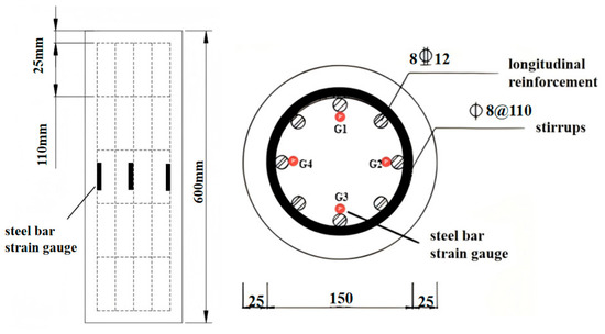
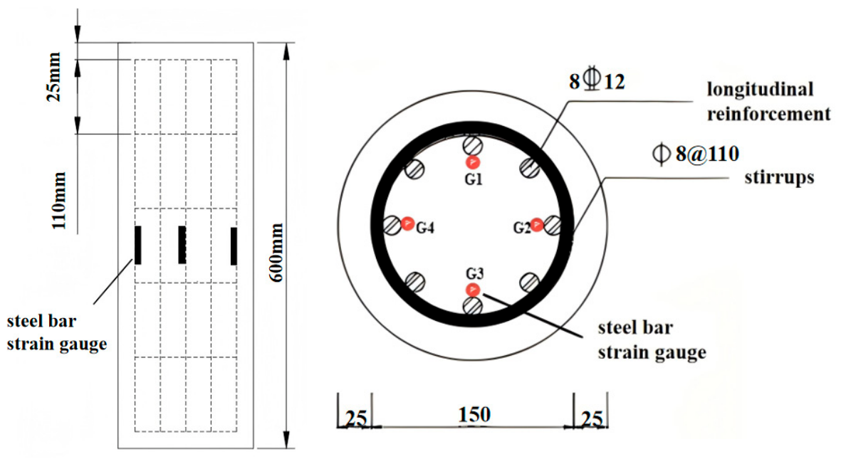
The short columns were designed with a slenderness ratio of L/D = 3, where D = 200 mm and L = 600 mm. Longitudinal and transverse reinforcement were detailed according to the Code for Design of Concrete Structures (GB 50010-2010) [31]. Each column included eight longitudinal HRB400 steel bars with a diameter of 12 mm. The transverse reinforcement consisted of HPB300 steel hoops with a diameter of 8 mm, spaced at 110 mm. The concrete cover thickness was 25 mm. The reinforcement layout is illustrated in Figure 4, and the design parameters of the ITSC short columns are summarized in Table 5.
Figure 4.
Schematic Diagram of Reinforcement Layout and Strain Gauge Positions for Reinforced Concrete Columns.
Table 5.
Design Parameters of RCSC.
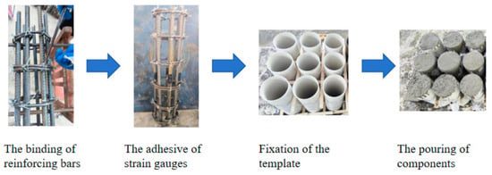
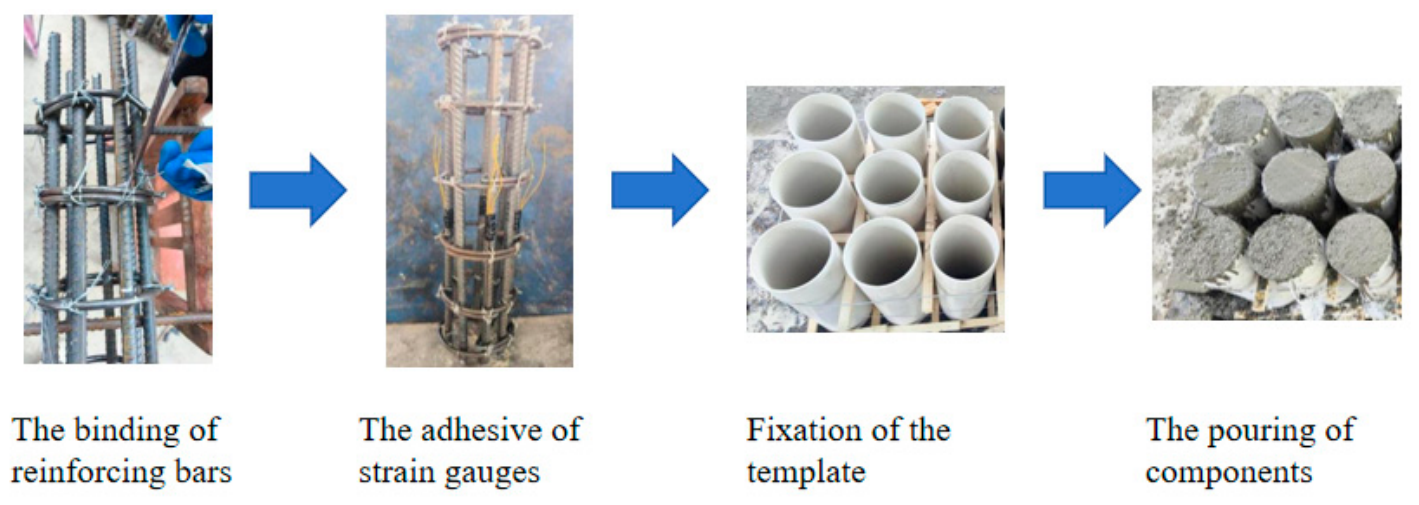
The RCSC were fabricated in accordance with the Code for Design of Concrete Structures (GB 50010-2010) [31] and the Standard for Experimental Methods of Concrete Structures (GB/T 50152-2012) [32]. The main procedures include the following: steel bar binding; strain gauges affixed at the mid-height (1/2 height) of four longitudinal steel bars at the 12 o’clock, 3 o’clock, 6 o’clock and 9 o’clock positions, as shown in Figure 4; formwork installation; and concrete pouring. The detailed procedures are illustrated in Figure 5.
Figure 5.
Fabrication process of the specimens.
2.4. Test Methods
2.4.1. Compressive Strength of Iron Tailings Sand Concrete
In this study, mix proportions and strength grade criteria for ITSC were first determined for three strength grades (C30, C40, C50) and six ITS replacement ratios (0%, 20%, 40%, 60%, 80%, 100%). Accordingly, fifty-four 100 mm × 100 mm × 100 mm cubic specimens were fabricated for eighteen mix proportions (three strength grades × six replacement ratios) to investigate the cubic compressive strength fcu of ITSC. Furthermore, to support the bearing capacity calculation of compression members in practical engineering using ITSC, fifty-four 150 mm × 150 mm × 300 mm prismatic specimens were prepared to determine the axial compressive strength fc of ITSC.
The specimens were prepared in accordance with the Standard for Experimental Methods of Physical and Mechanical Properties of Concrete (GB/T 50081-2019) [33]. The preparation procedure included cleaning and numbering the molds, cleaning and moistening the mixer, mixing the materials, and compacting and leveling the concrete. After casting, the specimens were left undisturbed for 24 h before demolding, and then the specimens were cured for 28 days in a standard curing chamber at 20 °C ± 2 °C with a relative humidity above 95%.
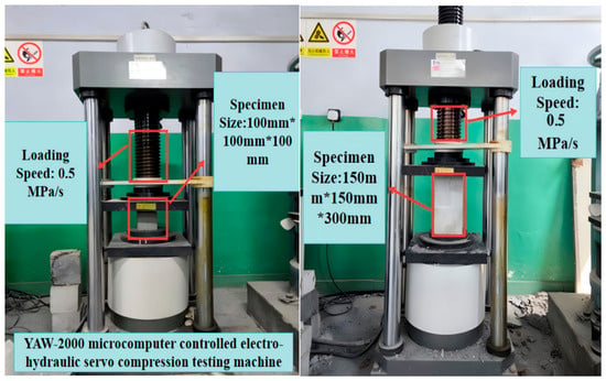
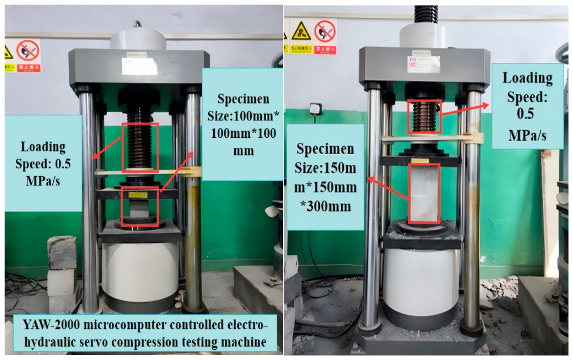
After 28 days of curing, the specimens were removed from the standard curing room and surface-dried. The experiment was conducted in accordance with the Standard for Experimental Methods of Physical and Mechanical Properties of Concrete (GB/T 50081-2019) [33]. A YAW-2000 (Changchun Keda Testing Machine Manufacturing Co., Ltd., Changchun, China) microcomputer-controlled electro-hydraulic servo compression testing machine was used. The lateral sides of the concrete cubes were placed as the bearing surfaces on the center of the lower platen. A continuous and uniform load was applied at a rate of 0.5 MPa/s until specimen failure occurred. The loading procedure is illustrated in Figure 6.
Figure 6.
Compressive Strength Experiment of Cubics and Axial Compressive Strength Experiment.
2.4.2. Loading of Reinforced Concrete Short Columns
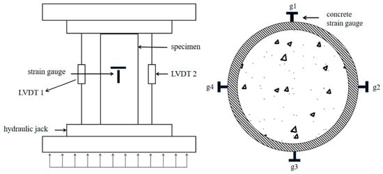
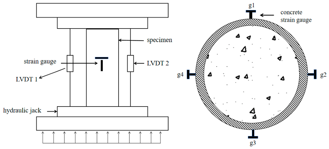
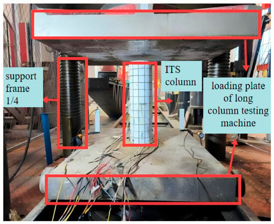
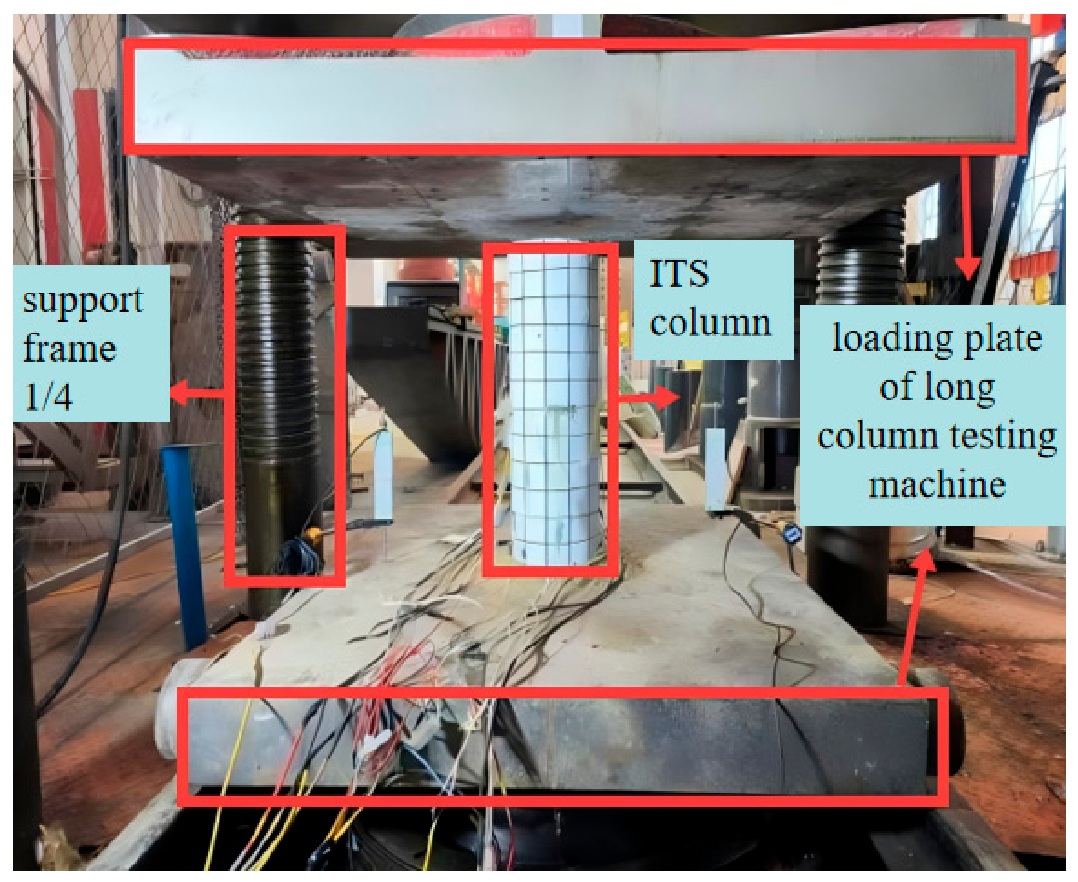
The RCSC was subjected to axial compression loading. To facilitate observation, the exterior surfaces of the specimens were painted and marked with a 50 mm × 50 mm grid prior to experimentation. Four sets of transverse and longitudinal concrete strain gauges were symmetrically attached around the mid-height of the columns to measure longitudinal and lateral strains during the experiment, as shown in Figure 7. Additionally, two YHD-100 LVDTs (Chengdu Electronic Measuring Sensing Technology Co., Ltd., Chengdu, China) were symmetrically installed on either side of each column to record vertical displacements. Axial loading was applied using a YAW-10000 (Changchun New Testing Machine Co., Ltd., Changchun, China) long-column experimental machine, with strain data collected via a DH-3821 data acquisition system (Chengdu Electronic Measuring Sensing Technology Co., Ltd., Chengdu, China). The experiment procedures followed the Standard for Experiment Methods of Concrete Structures (GB/T 50152-2012) [32]. Before loading, to prevent uneven contact due to concrete shrinkage, the top surfaces of the columns were leveled with fine sand (0.1–0.2 mm) to ensure full contact with the loading platen. The experiment preparation setup is shown in Figure 8.
Figure 7.
LVDT and positions of concrete strain gauges.
Figure 8.
Specimens before loading.
The experiment employed a staged load control method based on both force and displacement. The loading procedure was as follows.
First, a preloading step was applied at 10% of the calculated ultimate axial load to verify the alignment of the specimen with the experimental machine, ensure full contact at the loading surfaces, and confirm that all instrumentation was functioning properly. Next, formal loading was conducted at a rate of 1 kN/s, in 50 kN increments, with a 2 min hold at each stage to observe the specimen’s damage behavior. When the applied load reached 70% of the calculated ultimate axial capacity, the loading rate was switched to 1 mm/min and continued until complete failure of the column.
3. Results and Discussion
3.1. Basic Mechanical Properties of Iron Tailings Sand Concrete
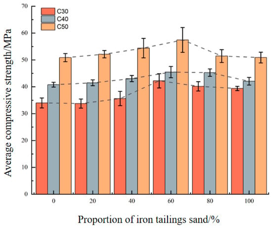
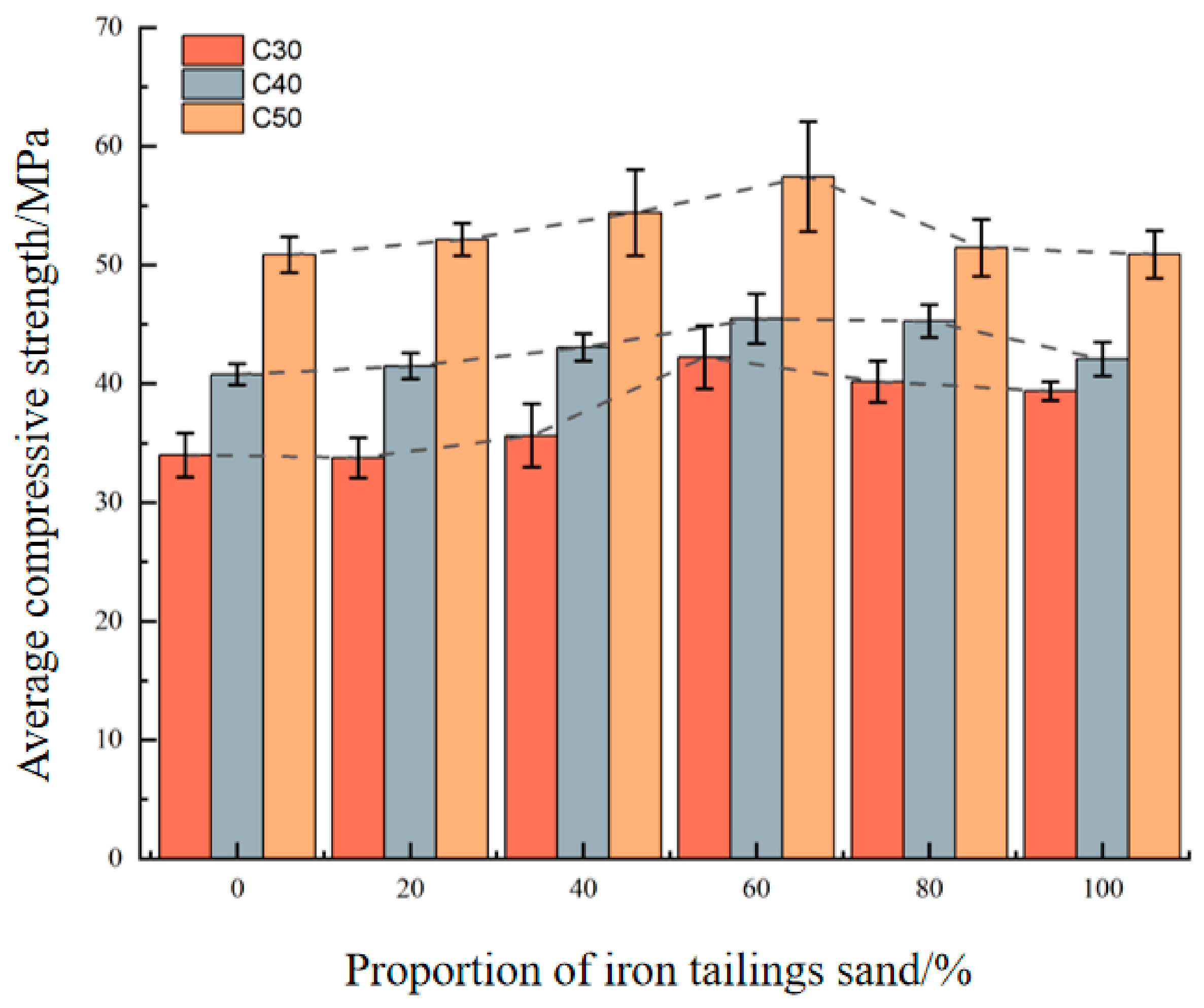
Based on the loads obtained in Section 2.4.1, the cubic compressive strength fcu and axial compressive strength fc of the prisms were calculated in accordance with the Standard for Experimental Methods of Physical and Mechanical Properties of Concrete (GB/T 50081-2019) [33], with three specimens per group averaged for final values. The variation in cubic compressive strength with ITS replacement ratio is illustrated in Figure 9 as a bar chart with error bars denoting standard deviation. The statistical results validate the reliability of test data for subsequent bearing capacity analysis.
Figure 9.
Cubic Compressive Strength fcu of ITSC.
Figure 9 shows that the cubic compressive strengths of C30, C40 and C50 ITSC all follow an increasing-then-decreasing trend with rising ITS replacement ratio, and the maximum strength is uniformly achieved at 60% replacement. Specifically, the strength growth ranges are 4.8–24.3%, 1.7–11.5% and 0.06–12.9% for the three strength grades, respectively, with C30 concrete exhibiting the largest improvement of 24.3%. This trend is attributed to the combined effect of particle filling and water absorption. At low replacement ratios, finer ITS particles fill the voids between cement paste and coarse aggregate, optimize the overall particle gradation, and improve the packing density of the mixture, thus enhancing compressive strength. Such an improvement is more significant for C30 concrete, as its higher water–cement ratio provides sufficient water for the secondary hydration of active components in ITS. When the replacement ratio exceeds 60%, the high specific surface area of ITS consumes excessive mixing water, and excessive ITS also dilutes the effective cementitious content per unit volume. These two factors jointly increase the actual water–cement ratio and internal porosity, weakening the strength enhancement effect.
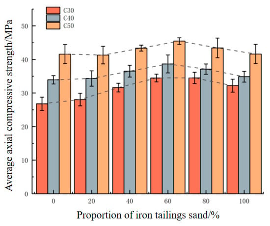
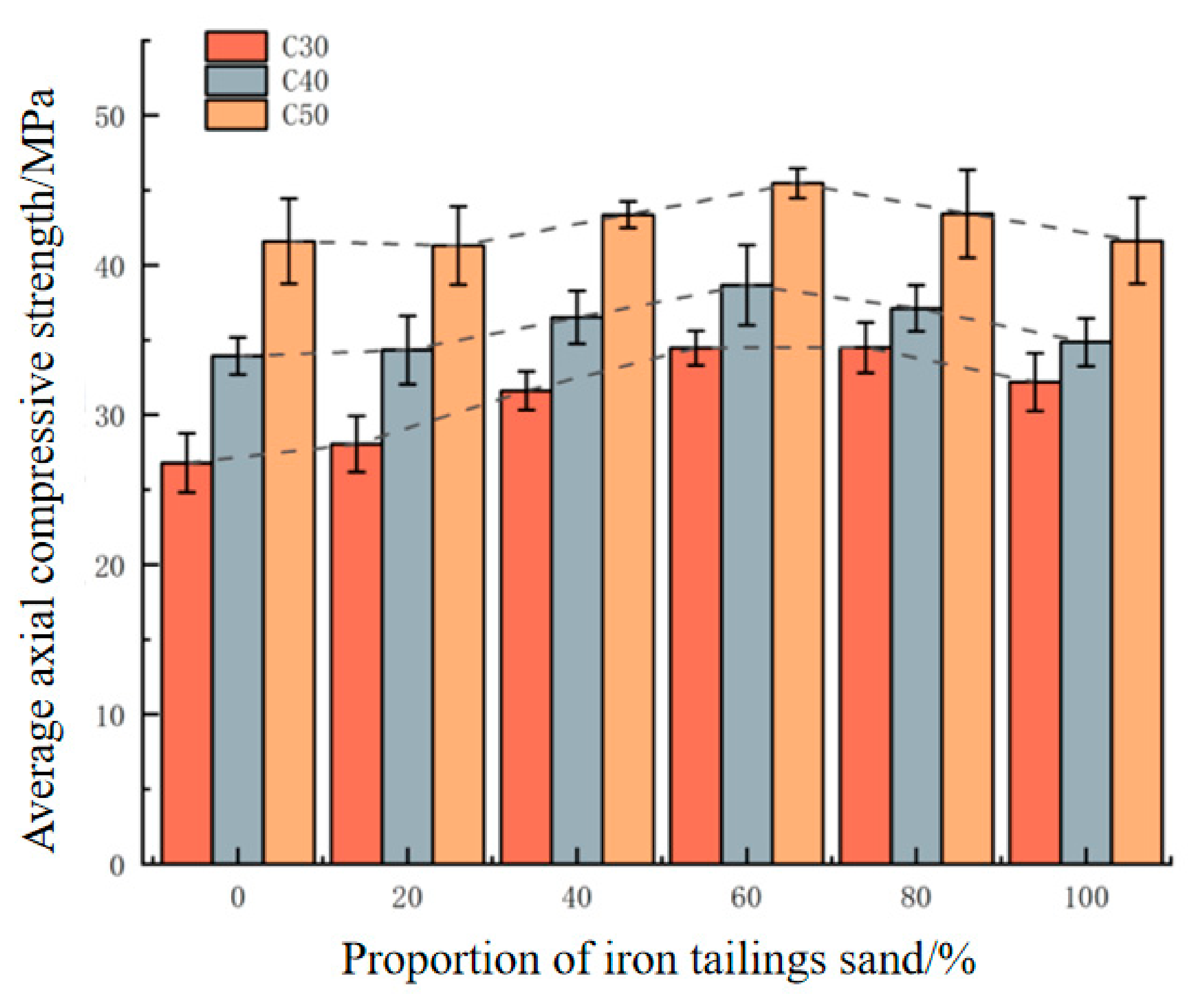
Figure 10 presents the axial compressive strength of ITSC with error bars representing standard deviation. The statistical results confirm the good reliability of the test data, which can support the subsequent bearing capacity analysis.
Figure 10.
Axial Compressive Strength fc of ITSC.
Figure 10 shows that the axial compressive strength of ITSC follows the same increasing-then-decreasing trend as its cubic compressive strength, peaking at 60% ITS replacement. Compared with ordinary concrete, the axial strength of T60, W60 and K60 increases by 8.7%, 13.4% and 9.3%, respectively. Notably, ITSC outperforms ordinary concrete in axial compressive strength at all replacement ratios. The strength enhancement stems from combined physical and chemical effects. Physically, the angular, rough surface of crushed ITS improves mechanical interlocking with cement paste, while its high-hardness quartz components form a rigid internal skeleton to share and transfer loads. Chemically, ultra-fine ITS particles exhibit slight pozzolanic activity, reacting with cement hydration products to generate supplementary C-S-H gel and densify the matrix; trace metal elements in ITS also catalyze hydration and optimize hydration product morphology.
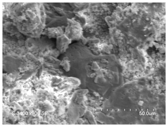
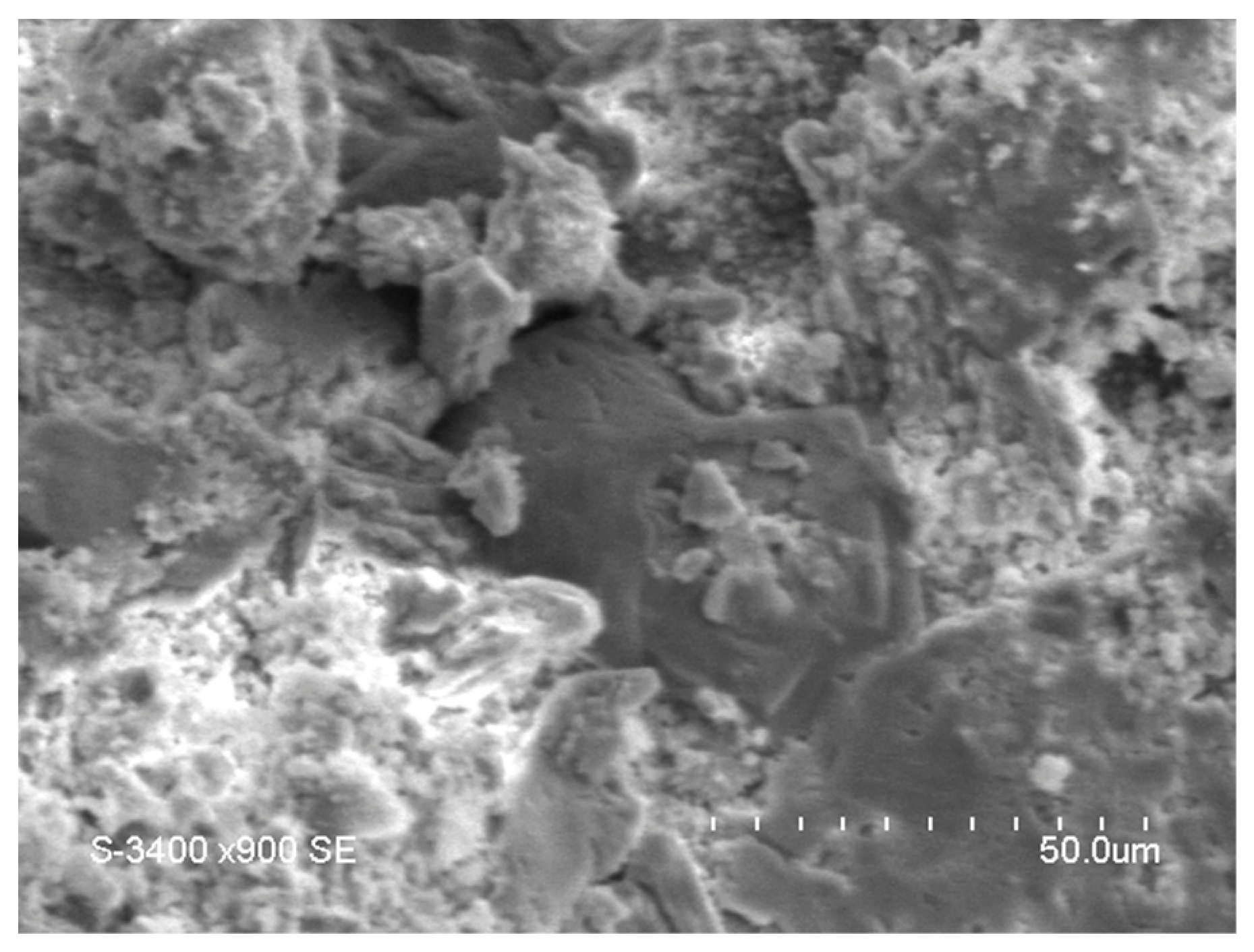
Scanning electron microscopy (SEM) was employed to further investigate the microstructure of ITSC and its functional mechanisms within the concrete matrix. This analysis provides insights into the mechanical performance and failure behavior of ITSC. The SEM instrument used was an S-3400N scanning electron microscope (Hitachi Ltd., Tokyo, Japan). Two concrete fragments were selected from different fracture surfaces of the compressive strength specimens as samples. After gold sputtering, the specimens were placed at the scanning port for observation once the SEM equipment was calibrated to further reveal the microscale reinforcement mechanism.
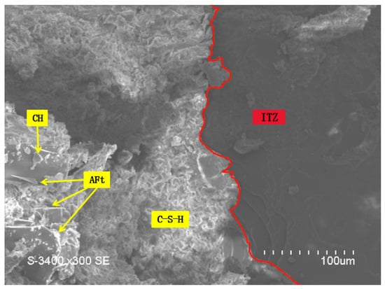
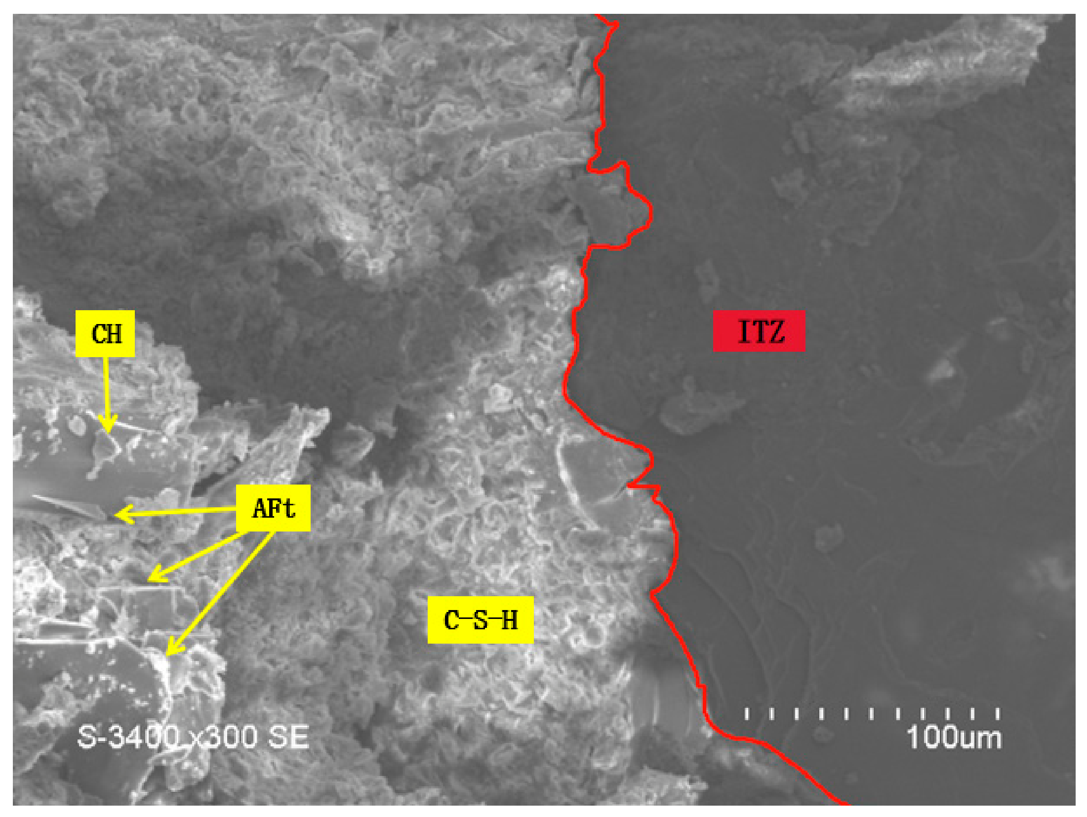
The interfacial zone between aggregate and cement paste is defined as the interfacial transition zone (ITZ) [34]. The ITZ is the weakest region in concrete, where cracks usually initiate. Figure 11 shows the microscopic morphology inside ITSC. A large amount of flocculent, acicular and lamellar substances can be observed around the ITZ. Combined with relevant studies, these substances are inferred to be hydration products such as ettringite (AFt), calcium hydroxide (CH), and calcium silicate hydrate (C-S-H). The above microscopic phenomena indicate that ITS possesses potential pozzolanic activity and may undergo secondary hydration reactions with the cement system. It can consume part of CH and promote the formation of AFt crystals and C-S-H gel. These hydration products interweave and precipitate in a layered form, which ameliorates the inherent defects in the ITZ, fills partial internal pores of the matrix, optimizes the microstructure, and improves the internal compactness. Accordingly, it provides a microscopic basis for the enhancement of the macroscopic mechanical properties of concrete.
Figure 11.
ITZ between aggregate and cement paste.
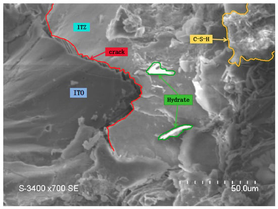
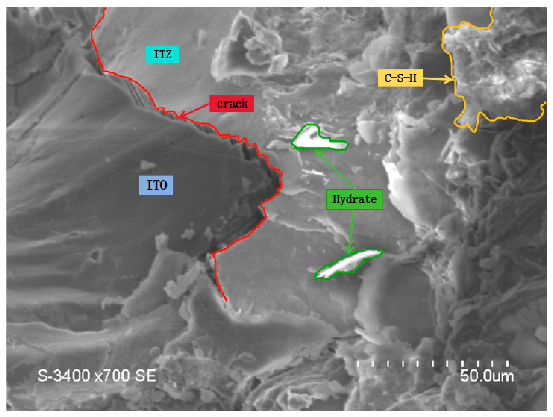
Figure 12 shows the microscopic morphology of the fracture surface between ITZ and ITS. It can be clearly observed from the zigzag fracture zone that the irregular surface morphology of ITS forms excellent mechanical interlocking between the cement paste and ITZ. Compared with natural river sand, such mechanical interlocking effect is more prominent. More energy is consumed when damage occurs at the bonding interface between ITS and ITZ, which delays the further propagation and extension of cracks and reduces the probability of penetrating cracks. This exerts a distinct positive effect on the improvement in concrete mechanical properties, and this conclusion is directly supported by SEM microscopic observations.
Figure 12.
Microscopic failure modes of ITSC.
3.2. Failure Modes and Crack Morphology
The loading process of ITS reinforced concrete short columns can be divided into three distinct stages: the elastic stage, the plastic working stage, and the failure stage.
- (1)
- Elastic Stage: During the initial loading phase, the applied load is relatively low. The strains of both concrete and steel reinforcement increase linearly with the applied load, showing a positive correlation. No visible changes are observed on the exterior of the specimen.
- (2)
- Plastic Working Stage: When the load reaches approximately 70–80% of the anticipated ultimate capacity, plastic deformations begin to appear in the concrete. Cracks initiate at the ends of the columns, and the strain in the steel reinforcement increases at a rate faster than that of the applied load.
- (3)
- Failure Stage: As the load continues to increase, cracks propagate and multiply, extending toward the midsection of the column and forming diagonal cracks. The load–displacement curve becomes nearly linear. Upon reaching the ultimate load capacity, the applied load starts to decrease, accompanied by progressive spalling and crushing of the external concrete, ultimately leading to the complete failure of the column.
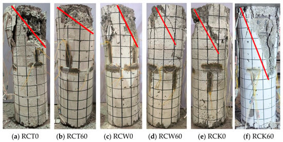
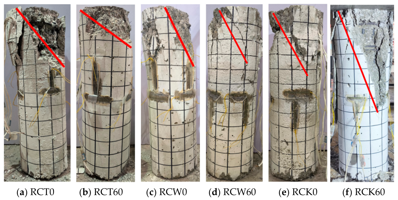
The ultimate failure mode of the specimens is illustrated in Figure 13. Across all levels of ITS incorporation, the failure patterns of the columns were generally consistent. Cracks initially developed at the column ends and subsequently propagated diagonally toward the mid-height. Upon reaching the ultimate load, the concrete at the ends was crushed, the longitudinal reinforcement became exposed and buckled, and the column ultimately failed.
Figure 13.
Failure modes of ITS RCSC (the red line in the figure indicates the direction of the failure section).
3.3. Ultimate Bearing Capacity
Based on the experimental results, the load-bearing capacities of RCSC with three different concrete grades were determined under two conditions: without ITS and with a 60% replacement of ITS. The results are summarized in Table 6.
Table 6.
Load-Bearing Capacities of ITS RCSC.
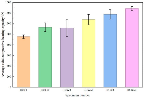
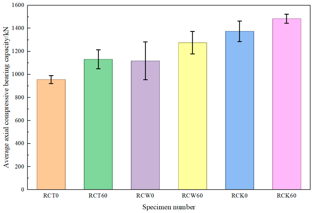
To analyze the variation in load-bearing capacity with different levels of ITS replacement, the data in Table 6 are plotted as error bar histograms, as shown in Figure 14. Under the three strength grades of C30, C40 and C50, the bearing capacity of RCSC with 60% ITS replacement ratio is increased by 18%, 14.1% and 8.1%, respectively, compared with ordinary concrete short columns of the same strength grade. The results indicate that, under the test conditions of a 60% ITS replacement ratio, specific column shape, steel reinforcement ratio, concrete strength gradient and concentric axial load, the incorporation of ITS exerts a positive strengthening effect on such RCSC. Among them, the strengthening effect is the most prominent for C30 strength grade concrete. This effect can be attributed to the higher water-to-cement ratio of C30 concrete, which provides more free water to facilitate the hydration of cement in combination with ITS, thereby improving the internal microstructure and enhancing the efficiency of strength gain.
Figure 14.
Ultimate load-bearing capacities of RCSC.
3.4. Concrete Strain Curves
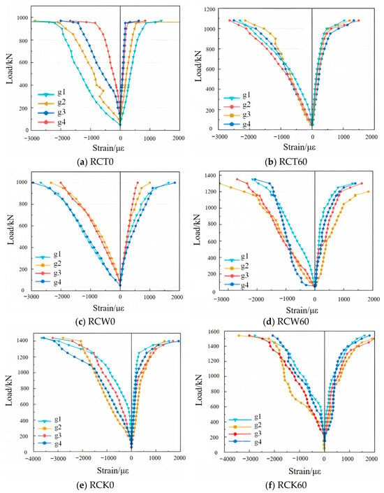
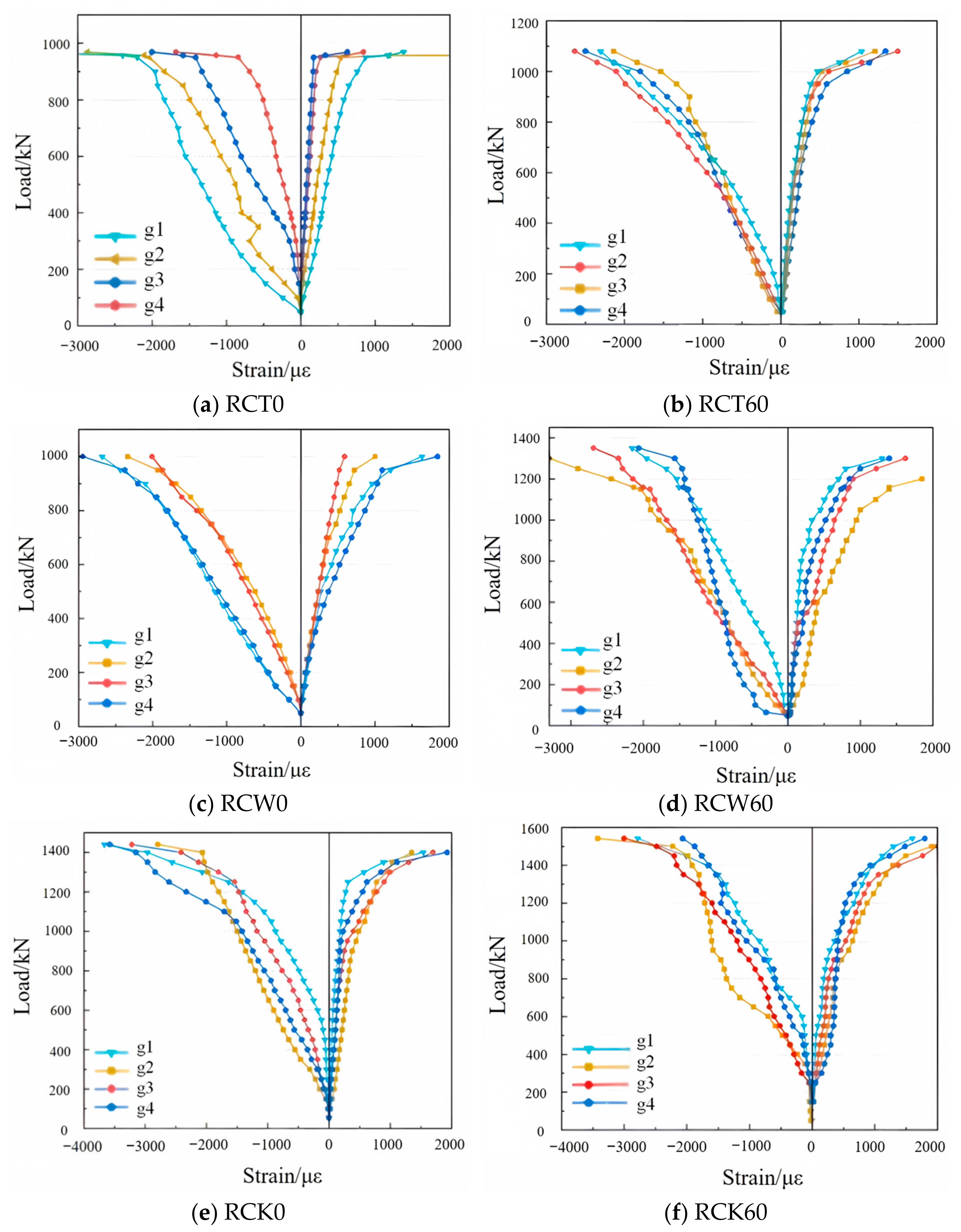
In the axial compression test of RCSC, BX120-3AA (Chengdu Electronic Measuring Sensing Technology Co., Ltd., Chengdu, China) strain gauges were used to measure the longitudinal and transverse strains of concrete. The strain gauges were pasted on the middle side of short columns, fixed with 502 glue and insulated for protection. The DH3821N (Chengdu Electronic Measuring Sensing Technology Co., Ltd., Chengdu, China) strain acquisition system was adopted for data collection. The measurement procedure was as follows: the system was zero-calibrated first, then loads were applied step-by-step. After each load level was stabilized for 30 s, the corresponding longitudinal and transverse strain data were collected, recorded synchronously, and used to plot load-strain curves., as shown in Figure 15. Strain groups 1–4 are denoted as g1–g4, respectively. In the figure, the left side represents longitudinal strains, while the right side represents transverse strains. As the strain behavior was found to be similar across specimens, only one short column from each group is discussed for clarity.
Figure 15.
Load–strain curves of concrete in RCSC.
As shown in Figure 15, load is approximately linearly correlated with concrete strain in the elastic stage. Specimens enter the plastic stage with accelerated strain growth when the load reaches 70–80% of the ultimate load. The load–strain behaviors are similar for different ITS replacement ratios, indicating that the replacement ratio has little effect on deformation characteristics. All specimens exhibit consistent curve shapes in the failure stage. ITS-reinforced concrete short columns have an axial compression performance similar to ordinary ones, with improved ultimate bearing capacity.
3.5. Steel Bar Strains
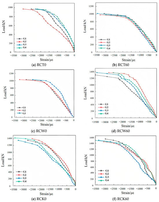
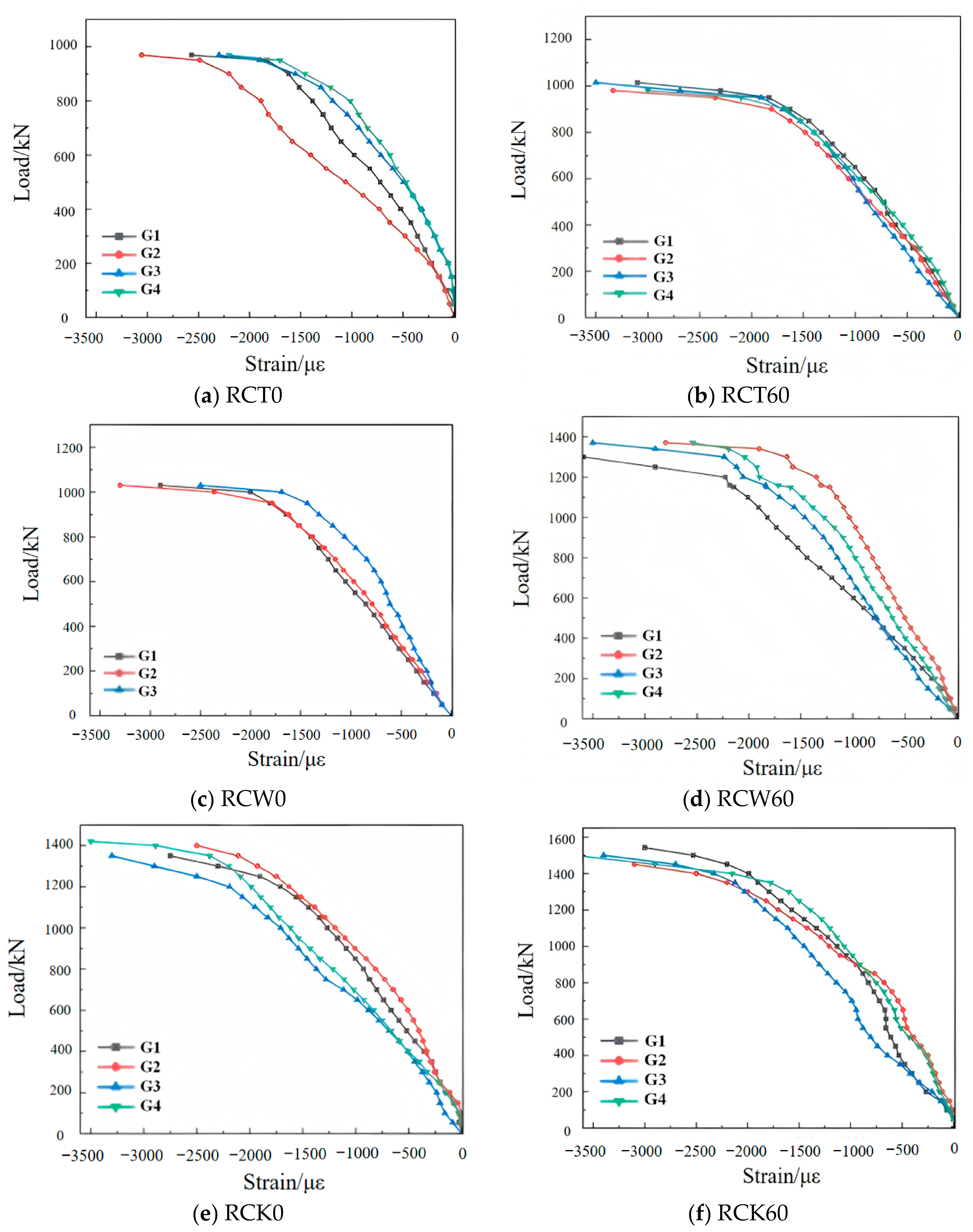
Longitudinal strain data of steel bars in each group of specimens were collected using WDL-50 displacement transducers fixed at the exposed ends of steel bars, with data synchronously acquired by the DH3821N data acquisition system. The measurement procedure was as follows: the system was zero-calibrated first, followed by step-by-step loading. After each load level stabilized for 30 s, longitudinal strain data of steel bars were recorded and processed to plot load–strain curves of steel bars, Strain gauges 1 to 4 on the steel reinforcement are denoted as G1 to G4 respectively, as shown in Figure 16.
Figure 16.
Load–strain curves of reinforcement in RCSC.
As observed from the load–strain curves in Figure 16, the dispersion of steel reinforcement strain among the specimen groups is relatively small, indicating the high reliability of the experimental data. Moreover, the yield strain of the steel reinforcement for each group is approximately in the range of 1950–2200 με, which is close to the theoretically calculated values. This demonstrates that the steel reinforcement can fully develop its capacity when the columns reach the ultimate load.
3.6. Load–Deflection Curves
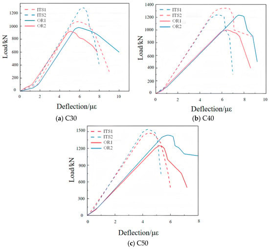
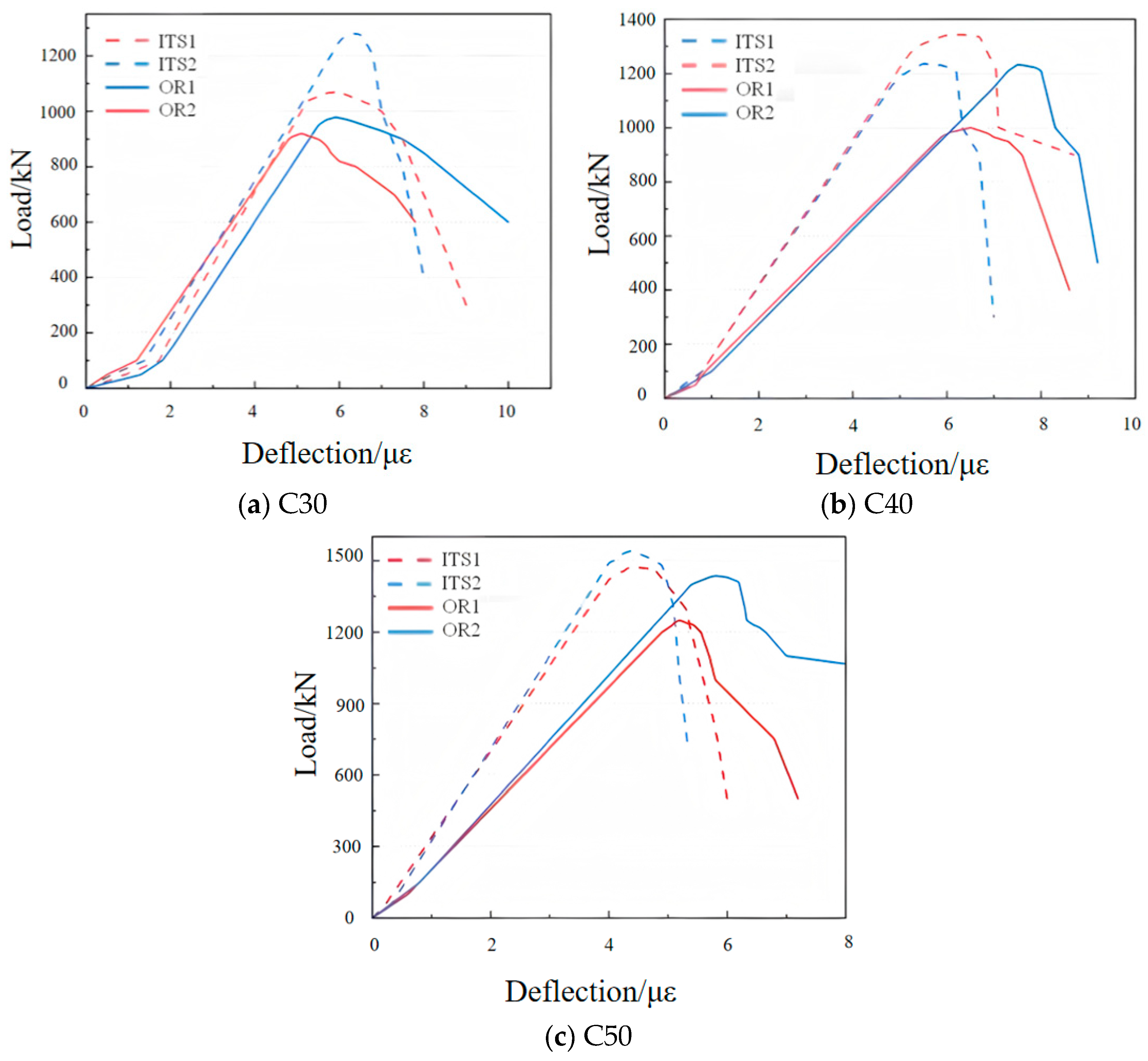
The load–displacement curves of RCSC with different grades and varying levels of ITS replacement are shown in Figure 17. After collecting the longitudinal displacement data at the exposed ends of steel bars via displacement transducers, the strain values were calculated using the formula ε = ΔL/L, where ε is the longitudinal strain of steel bars, ΔL is the longitudinal displacement measured by displacement transducers, and L is the effective length of steel bars. Columns of ITS 1 and 2 are denoted as ITS1 and ITS2 respectively. Ordinary reinforced concrete columns 1 and 2 are denoted as OR1 and OR2 respectively. At the initial stage of loading, the curves exhibit a noticeable inflection point, which is attributed to the rapid displacement caused by the crushing of the fine sand spread on the top of the specimens prior to loading. Shortly thereafter, the columns enter the elastic stage, where the load–displacement curves increase linearly with minimal scatter, indicating stable elastic modulus and uniform deformation of the materials during the initial loading phase. As the applied load approaches the failure load, the curves drop sharply, reflecting the loss of load-bearing capacity and large displacements characteristic of the failure stage. Furthermore, under the same concrete grade, columns with ITS show steeper ascending slopes in their load–displacement curves, indicating that the incorporation of ITS enhances the stiffness of the RCSC to some extent, thereby contributing to improved structural stability and deformation resistance.
Figure 17.
Load–displacement curves of RCSC at the same strength with different replacement ratios.
4. Load Capacity Calculation
To promote the broader application of ITS in reinforced concrete structures, it is necessary to establish an appropriate formula for calculating the load-bearing capacity of RCSC incorporating ITS. By modifying the axial compressive capacity formulas for ordinary reinforced concrete columns provided in domestic and international standards for concrete structure design, a calculation method suitable for ITS RCSC is derived.
4.1. Relevant Load-Bearing Capacity Formulas
The axial compressive capacity formulas for ordinary reinforced concrete columns, as provided in domestic and international standards for concrete structure design, are summarized in Table 7.
Table 7.
Load-Bearing Capacity Calculation Formulas According to Relevant Standards.
Here, represents the axial compressive stability coefficient of reinforced concrete columns. Since the specimens in this study are short columns, = 1 can be adopted. denotes the axial compressive strength of concrete (MPa), and is the cross-sectional area of concrete (mm2). is the yield strength of the longitudinal reinforcement (MPa), and represents the total cross-sectional area of the longitudinal reinforcement (mm2). refers to the standard value of the cubic compressive strength of concrete (MPa), and is the gross cross-sectional area of the member, which is 40,000 mm2 for all specimens in this study.
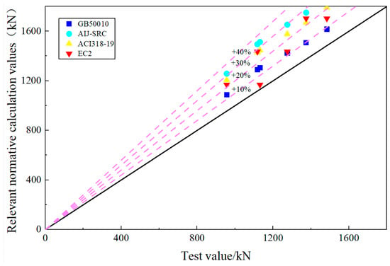
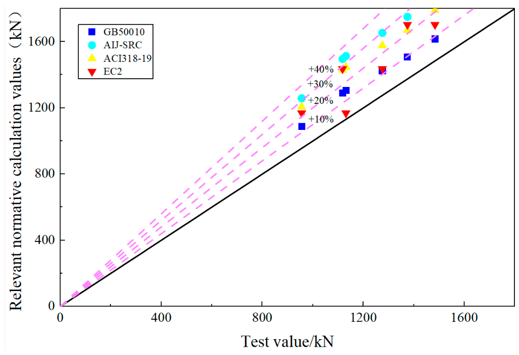
Based on the above standard methods for calculating load-bearing capacity, the calculated capacities of the short columns under the same conditions are summarized in Table 8 and compared with the experimentally measured values. Statistical indicators, including the mean and standard deviation, were computed and are presented in Table 8 to assess the data dispersion. The corresponding variation trends are illustrated in Figure 18.
Table 8.
Comparison and Analysis of Calculated and Experimental Bearing Capacities of RCSC.
Figure 18.
Comparison trends of the load-bearing capacities of reinforced concrete columns according to relevant standards.
The average ratios of the calculated values to the experimental values, obtained using the formulas from GB50010-2010: Code for Design of Concrete Structures [31] and Eurocode 2: Design of Concrete Structures (EC2) [37], are 1.13 and 1.18, respectively. In comparison, the average ratios for JGC15 and ACI318-19 are 1.31 and 1.25, respectively. These results indicate that the formulas in GB50010-2010 and EC2 are closer to the experimental outcomes of this study. Therefore, the subsequent modifications for calculating the load-bearing capacity of ITS RCSC are based on the GB50010 formula.
4.2. Modification of the Load-Bearing Capacity Formula
Using Origin (2025b) software, the experimental values were fitted against fc, resulting in a linear relationship between N0 and fc, as expressed in Equation (1).
Based on the GB50010 calculation formulas, the load-bearing capacity formula for reinforced concrete columns incorporating ITS is summarized as Equation (2).
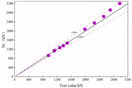
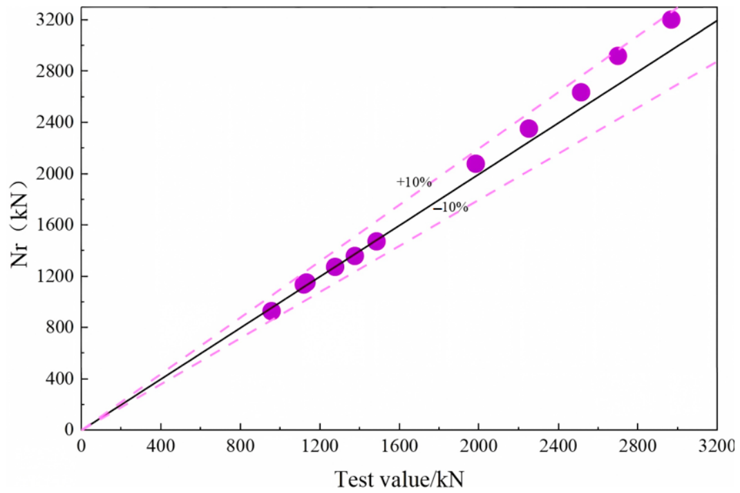
The modified calculated load-bearing capacities of the ITS RCSC were compared with the experimental values. Additionally, five sets of column experiment results reported by Li Sujuan [38] (corresponding to specimens WC30-1, WC35-1, WC40-1, WC45-1, and WC50-1 in Table 9) were included for comparison, as summarized in Table 9. The corresponding trends are illustrated in Figure 19.
Table 9.
Comparison of the Modified Calculated and Experimental Load-Bearing Capacities.
Figure 19.
Comparison between the calculated and experimental load-bearing capacities.
The revised calculated values show good agreement with the test results. The average ratio of revised bearing capacity to test bearing capacity is 1.0282, with a standard deviation of 0.035 and a maximum error of 8%. The revised calculation formula exhibits low dispersion, favorable stability and high prediction accuracy. Given that the formula calibration was performed based on a relatively limited number of experimental specimens, this section further defines the applicable boundary, statistical confidence level and parameter sensitivity of the correction factor. This formula is only applicable to the parameter range adopted in this study, namely the concrete strength and reinforcement ratio tested herein. The reliability of the correction factor will decrease and the formula cannot be directly extrapolated when the concrete strength or reinforcement ratio exceeds the experimental range of this work. Within the scope of test parameters in this paper, the proposed formula can provide theoretical references for the engineering design of RCSC incorporating ITS with the same mixture proportion.
5. Conclusions
This study investigated the effects of varying ITSC replacement ratios on the strength of concrete materials across different concrete grades, from both macroscopic mechanical and microscopic structural perspectives. Based on these findings, the optimal ITSC was applied to three concrete grades to fabricate RCSC, which were then subjected to axial compression experiments. The failure mechanisms of the columns were analyzed in terms of failure modes, load–strain relationships, and load–displacement responses. Based on the above research, the following conclusions can be drawn:
- (1)
- The effect of ITS replacement on the compressive performance of concrete exhibits a rising-then-declining trend, with 60% identified as the optimal replacement ratio. For C30, C40, and C50 concrete grades at the optimal content, the cubic compressive strengths increased by 24.3%, 11.5%, and 12.9%, respectively, while the corresponding axial compressive strengths increased by 8.7%, 13.4%, and 9.3%.
- (2)
- SEM analysis shows that the surface of ITS is rough and has high stiffness, which can assist in the hydration reaction and optimize the microstructure; however, excessive mixing can increase water absorption and affect strength.
- (3)
- The failure modes and processes of RCSC incorporating ITS are generally consistent with those of ordinary concrete columns. At the optimal replacement ratio of 60%, the load-bearing capacities of C30, C40, and C50 short columns increased by 18%, 14.1%, and 8.1%, respectively.
- (4)
- Based on the experimental data and the relevant literature, the GB50010-2010 formula for the axial compressive capacity of RCSC was modified to derive a calculation formula applicable to ITS reinforced concrete. The modified formula exhibits low dispersion, good stability, and high predictive accuracy. This formula is applicable to specimens under the tested material, strength grade, steel reinforcement configuration and axial compression conditions.
- (5)
- The conclusions of this study are only applicable to RCSC with ITS under axial compression. The application of ITS in reinforced concrete long columns and eccentric compression members, as well as the durability in practical engineering, are not covered.
- (6)
- Relevant research will be carried out in the future to broaden its engineering application scope and promote the resource utilization of ITS. The relevant research results can fill the technical gaps in this field and form a systematic applied technical system. This could not only fully exploit the utilization value of ITS and realize the harmless and resourceful disposal of solid waste, it could also provide references for the engineering application of building materials made from similar tailings, with remarkable economic, social and ecological benefits.
Author Contributions
Methodology, Y.Z.; Software, S.Z. and C.Z.; Validation, C.Z.; Formal analysis, C.L. and L.J.; Investigation, Y.Z.; Resources, J.L.; Data curation, Y.Z.; Writing—original draft, S.Z.; Writing—review and editing, S.Z.; Visualization, C.L., B.W. and L.J.; Supervision, J.L.; Project administration, J.L.; Funding acquisition, J.L. All authors have read and agreed to the published version of the manuscript.
Funding
This research was funded by the Science and Technology Development Project of Jilin Provincial Department of Science and Technology (YDZJ202302CXJD052).
Data Availability Statement
The original contributions presented in this study are included in the article. Further inquiries can be directed to the corresponding author.
Conflicts of Interest
The authors declare no conflicts of interest.
References
- Du, X.; Fu, G.H.; Chu, H.C.; Yang, X.; Fu, Y.; Dong, Z.; Liu, J.; Man, X.; Zhi, H. Characteristics analysis of iron tailings and current status and prospects of its utilization technology. China Min. Mag. 2024, 33, 115–124. [Google Scholar]
- Zhao, Q.; Chen, L.; Wang, X.; Zhang, S.; Li, F. Study on the modification effect and mechanism of composite solid waste and steel fiber on the mechanical properties of concrete. Front. Mater. 2024, 11, 1431648. [Google Scholar] [CrossRef] [Scilit]
- Ministry of Natural Resources of the People’s Republic of China. China Mineral Resources Report 2023; Geological Publishing House: Beijing, China, 2023.
- Wu, Y.; Yuan, X.; Fu, H.; Lin, S.; Xu, X.; Zhou, Y.; Wang, X. Stabilization of dispersive soil by iron ore tailings: A sustainable solution combining waste valorization and geotechnical enhancement. Miner. Eng. 2026, 246, 110409. [Google Scholar] [CrossRef] [Scilit]
- Wu, J.; Chen, L. Prediction of Bond Strength between FRP Bars and UHPC using Explainable Machine Learning Algorithms. J. Build. Eng. 2026, 119, 115174. [Google Scholar] [CrossRef] [Scilit]
- Li, J.; Chen, L.; Luo, J.; Zhu, W.; Fan, X.; Zhu, Y.; Zhang, Z. Mechanical properties and microscopic characteristics of steel fiber coal gangue concrete. Front. Mater. 2023, 10, 1211129. [Google Scholar] [CrossRef] [Scilit]
- Zhao, G.; Ni, X.; Chen, Z.; Huang, W.; Ding, S.; Yang, K.; Zhu, J.; Wei, F.; Bao, L. A potential sustainable way for iron tailings sand in cast-in-situ concrete subjected to sulfate-chloride attack: Performance and mechanisms. J. Sustain. Cem.-Based Mater. 2026, 15, 2059–2079. [Google Scholar] [CrossRef] [Scilit]
- Zhang, Z.; Zhang, Z.; Yin, S.; Yu, L. Utilization of Iron Tailings Sand as an Environmentally Friendly Alternative to Natural River Sand in High-Strength Concrete: Shrinkage Characterization and Mitigation Strategies. Materials 2020, 13, 5614. [Google Scholar] [CrossRef] [Scilit] [PubMed]
- Zhang, J.; Chen, L.; Xu, W.; Wang, Y.J.; Chu, Y. Experimental study on mechanical properties and shrinkage deformation of C40 iron tailing sand concrete. New Build. Mater. 2026, 53, 1–4. [Google Scholar]
- Li, Z. Study on mechanical properties of iron tailings sand concrete. Sichuan Cem. 2020, 2, 10. [Google Scholar]
- Shettima, A.U.; Hussin, M.W.; Ahmad, Y.; Mirza, J. Evaluation of iron ore tailings as replacement for fine aggregate in concrete. Constr. Build. Mater. 2016, 120, 72–79. [Google Scholar] [CrossRef] [Scilit]
- Fang, Y.; Qiao, L.; Hu, T.; Zhang, L.; Long, H.; Yu, F.; Yang, Z. Characteristics of Iron Ore Tailings Sand and Properties of Iron Ore Tailings Sand Concrete: A Review. Int. J. Concr. Struct. Mater. 2025, 19, 41. [Google Scholar] [CrossRef] [Scilit]
- Yu, F.; Wang, D.; Fang, Y.; Wang, H.; Wang, Z.; Xu, B.; Yang, Z.; Xu, L. Basic mechanical properties of ultra-fine iron tailings sand concrete. Case Stud. Constr. Mater. 2025, 23, e05213. [Google Scholar] [CrossRef] [Scilit]
- Zhu, Z.; Li, B.; Zhou, M. The Influences of Iron Ore Tailings as Fine Aggregate on the Strength of Ultra-High Performance Concrete. Adv. Mater. Sci. Eng. 2015, 2015, 412878. [Google Scholar] [CrossRef] [Scilit]
- Li, N.; Niu, L. Research Progress on the Impact of Iron Tailings Replacing Concrete Aggregates on Concrete Performance. Adv. Res. 2025, 26, 268–286. [Google Scholar] [CrossRef] [Scilit]
- Wang, Y.G.; Wang, H.R.; Cao, H.L.; Fan, Y.L. Study on the Influence of Iron Tailings Sand Replacement Ratios on the Properties of Concrete. China Concr. 2025, 10, 42–46. [Google Scholar]
- Ning, B.K.; Xu, Y.Z.; Cui, K.; Wang, N. Stress-strain full curve characteristics of iron tailing sand concrete. J. Shenyang Univ. Technol. 2021, 43, 573–578. [Google Scholar]
- Duan, P.; Yan, C.; Zhou, W.; Ren, D. Fresh properties, compressive strength and microstructure of fly ash geopolymer paste blended with iron ore tailing under thermal cycle. Constr. Build. Mater. 2016, 118, 76–88. [Google Scholar] [CrossRef] [Scilit]
- Ghannam, S.; Najm, H.; Vasconez, R. Experimental study of concrete made with granite and iron powders as partial replacement of sand. Sustain. Mater. Technol. 2016, 9, 1–9. [Google Scholar] [CrossRef] [Scilit]
- Karthikeyan, B.; Kathyayini, R.; Kumar, V.A.; Uthra, V.; Kumaran, S.S. Effect of dumped iron ore tailing waste as fine aggregate with steel and basalt fibre in improving the performance of concrete. Mater. Today-Proc. 2021, 46, 7624–7632. [Google Scholar] [CrossRef] [Scilit]
- Wang, W.; Chen, R.; Li, H.; Yin, Y.; He, M.; Xi, B. Mechanical performance and microcosmic characteristic of the iron ore tailings as fine aggregate and cementitious material at the recycled concrete. J. Build. Eng. 2025, 114, 114130. [Google Scholar] [CrossRef] [Scilit]
- Arbili, M.M.; Alqurashi, M.; Majdi, A.; Ahmad, J.; Deifalla, A.F. Concrete made with iron ore tailings as a fine aggregate: A step towards sustainable concrete. Materials 2022, 15, 6236. [Google Scholar] [CrossRef] [Scilit] [PubMed]
- Almada, B.S.; da Silva Neto, G.A.; do Prado, D.F.; Aguilar, M.T.P.; Garcia, D.C.S.; Silva, G.J.B.; dos Santos, W.J. Evaluation of the microstructure and micromechanics properties of structural mortars with addition of iron ore tailings. J. Build. Eng. 2023, 63, 105405. [Google Scholar]
- Liu, J.; Wu, Z.; Han, Y.; Wang, H.; An, M. Influence of Dosage of Iron Ore Tailings–Based Nonsintered Artificial Aggregates on the Strength and Microstructure of Ultrahigh-Performance Concrete. J. Mater. Civ. Eng. 2026, 38, 04026162. [Google Scholar] [CrossRef] [Scilit]
- Ma, X.; Sun, J.; Zhang, F.; Yuan, J.; Yang, M.; Meng, Z.; Bai, Y.; Liu, Y. Mechanical Behaviour Evaluation of Full Iron Tailings Concrete Columns under Large Eccentric Short-Term Loading. Materials 2023, 16, 2466. [Google Scholar] [CrossRef] [Scilit] [PubMed]
- Li, W.; Fan, M.H.; Jiao, Y.H.; Yang, P.; Ren, W.; Luo, T. Quantitative Model of Uniaxial Strength and Microstructure of Iron Ore Tailings Concrete. J. Archit. Eng. 2025, 31, 04025032. [Google Scholar] [CrossRef] [Scilit]
- Su, X.; Chen, J.; Zhao, Y. Study on the axial compressive properties of iron tailing sand concrete columns under high temperatures. Struct. Concr. 2025, 1–12. [Google Scholar] [CrossRef] [Scilit]
- JGJ 52-2006; Standard for Quality and Inspection Methods of Sand and Stone for Ordinary Concrete. China Architecture & Building Press: Beijing, China, 2006.
- GB 8076-2008; Specification for Concrete Admixtures. China Architecture & Building Press: Beijing, China, 2008.
- JGJ 55-2011; Specification for Mix Proportion Design of Ordinary Concrete. China Architecture & Building Press: Beijing, China, 2011.
- GB 50010-2010; Standard for Concrete Structure Design. China Architecture & Building Press: Beijing, China, 2010.
- GB/T50152-2012; Standard for Experiment Methods of Concrete Structures. China Architecture & Building Press: Beijing, China, 2012.
- GB/T 50081-2019; Standard for Experiment Methods of Physical and Mechanical Properties of Concrete. China Architecture & Building Press: Beijing, China, 2019.
- Wu, L.; Ju, X.; Liu, M.; Guan, L.; Ma, Y.; Li, M. Influences of multiple factors on the chloride diffusivity of the interfacial transition zone in concrete composites. Compos. Part B Eng. 2020, 199, 108236. [Google Scholar] [CrossRef] [Scilit]
- JGC15; Standard Specifications for Concrete Structures 2007 “Design”. Japan Society of Civil Engineers: Tokyo, Japan, 2007.
- ACI 318-19; Building Code Requirements for Structural Concrete and Commentary. American Concrete Institute (ACI): Farmington Hills, MI, USA, 2019.
- EN 1992-1-1 (2004); Eurocode 2: Design of Concrete Structures—Part 1-1: General Rules and Rules for Buildings. European Committee for Standardization (CEN): Brussels, Belgium, 2004.
- Li, S. Experimental Study of Axial Compression Behavior of Ferrous Tailing Reinforced Concrete Short Column Restraint by Stirrup. Master’s Thesis, School of Civil Engineering, Tangshan University, Tangshan, China, 2018; pp. 32–35. [Google Scholar]

Disclaimer/Publisher’s Note: The statements, opinions and data contained in all publications are solely those of the individual author(s) and contributor(s) and not of MDPI and/or the editor(s). MDPI and/or the editor(s) disclaim responsibility for any injury to people or property resulting from any ideas, methods, instructions or products referred to in the content. |
© 2026 by the authors. Licensee MDPI, Basel, Switzerland. This article is an open access article distributed under the terms and conditions of the Creative Commons Attribution (CC BY) license.