


Abstract
Composites are widely used in the building sector for high-rise building load-bearing components, bridge decks, prefabricated structural panels, and seismic-resistant members, where excellent mechanical performance and structural durability are critical. As specialized advanced composites, variable stiffness composites (VSCs) have gained increasing engineering applications due to their excellent overall performance. Nevertheless, exploring the fracture characteristics of composite materials, especially VSCs, remains a significant challenge. In particular, cracks in composite components can adversely affect structural integrity and durability. In this study, a dynamic fracture phase-field model for VSCs is developed within the framework of elastic dynamics to investigate crack propagation behavior of VSCs under dynamic loads. The proposed model is first validated by experimental results of fracture behavior of single-edge cracked FRC laminae. Then, the proposed model is employed to systematically study the effects of three fiber orientation design variables and internal defects on the fracture behavior of VSCs. Additionally, fiber trajectories are optimized for different pore distribution configurations. The results demonstrate that the model effectively captures the fracture behavior of VSCs and that optimizing these three design parameters enables the fabrication of high-performance VSCs with enhanced crack propagation resistance. This work provides fundamental insights for the design of curvilinearly fiber-reinforced composites and lays a solid theoretical foundation for the practical application of VSCs in building engineering.
1. Introduction
Fiber-reinforced composites (FRCs) typically consist of a reinforcement phase and a matrix phase and exhibit superior mechanical properties, including high specific strength, high specific modulus, and light weight [1]. They have been widely used in various fields such as construction, aerospace structures, the automotive industry, electromechanical systems, and smart systems [2,3,4]. In the field of structural engineering, composites have been widely adopted for diverse applications, including load-bearing structural components, building facade systems, roofing structures, thermal insulation panels, and interior decorative elements. Moreover, composite materials are well suited for building renewal, new construction, and structural renovation projects, exhibiting broad application potential in modern architecture.
With the rapid development of fabrication techniques such as automated fiber placement and three-dimensional (3D) printing, curvilinear fiber-reinforced composites have been successfully manufactured [5,6]. Due to variations in fiber orientation, curvilinear fiber-reinforced composites exhibit unique characteristics, such as stiffness that varies with position. Hence, curvilinear fiber-reinforced composites are also called variable stiffness composites (VSCs). In contrast to conventional straight fiber-reinforced composites, classified as constant stiffness (CSCs), VSCs can achieve superior performance through the rational design of fiber trajectories. These distinct properties enable VSCs to be deployed in more demanding service environments [7,8]. However, their variable stiffness also introduces new challenges in understanding their failure behavior.
During their service life, composite materials are inevitably subjected to external loads, leading to damage and fracture, which may ultimately result in the failure of the material or even the entire structure [9]. Therefore, a comprehensive understanding of the composite failure mechanisms is crucial to their successful development and application.
Predicting the initiation and propagation of cracks in materials and structures is highly challenging and has attracted considerable interest due to the complexity and importance of crack evolution. Traditional experimental methods require substantial resources and time, and their results are susceptible to human subjectivity [10]. In contrast, numerical methods have become an important tool for studying composite fracture behavior due to their low cost and high efficiency. Discrete crack models and smeared crack models are the two main types of numerical models currently used to simulate crack propagation [11,12]. For the discrete models, the extended finite element method (XFEM) can effectively describe crack propagation in structures by introducing cracks, interfaces, etc., as additional degrees of freedom, and it has been relatively widely used to simulate material damage and fracture behavior [13,14,15,16]. The XFEM offers several advantages, including the ability to model problems involving complex geometries and crack propagation, with reduced mesh dependence, thereby providing more accurate stress/displacement field solutions and fracture parameters [17]. However, the XFEM incurs higher computational costs due to the introduction of additional degrees of freedom and relies on predefined criteria to determine crack initiation and propagation directions. Furthermore, the XFEM is ineffective at modeling complex crack patterns such as branching, kinking, and merging [18,19]. Smeared crack models can describe the entire process of crack evolution—from nucleation to propagation—without explicitly tracking the crack surface topology. However, the smeared crack models fail to represent the smeared crack surface and crack tip precisely. Moreover, local damage models are prone to mesh dependency due to damage localization, whereas non-local damage models often exhibit excessively large damage zones [20,21,22].
To overcome the limitations of existing models and better characterize material fracture behavior and crack evolution, the phase-field model was proposed and has become widely adopted in the study of material fracture [23,24,25,26]. Bourdin et al. [27] combined regularization methods with the phase-field method and introduced an additional length scale parameter to control the crack width, thereby establishing the classical AT2 phase-field model. Wu et al. [28] proposed a novel unified phase-field theory model based on thermodynamic laws, which is applicable to solving damage and quasi-brittle failure problems and overcoming the limitation of the AT2 phase-field model that is only suitable for brittle materials. Pham et al. [29] proposed the AT1 phase-field model by using the phase-field order parameter itself as the geometric function of the crack. Miehe et al. [30] introduced a spectral decomposition of the strain tensor into positive and negative parts to distinguish tensile and compressive behavior, and applied the phase-field model to fracture analysis under quasi-static, dynamic, and multi-field coupled conditions. Amor et al. [31] decomposed the strain tensor into volumetric and deviatoric components to split the strain energy into tensile and compressive parts, and subsequently simulated crack propagation behavior under tensile and compressive loading conditions, respectively. Hofacker et al. [32] developed a phase-field fracture computational framework for dynamic problems. By employing a staggered algorithm to solve the dynamic fracture mechanics of solids, they successfully captured the evolution of complex crack patterns under dynamic loading conditions. Loew et al. [33] proposed a rate-dependent phase-field damage model by incorporating strain-rate dependence in the constitutive description of the bulk and investigated damage behavior in rubber materials. Sridhar et al. [34] proposed a phase-field method to simulate crack propagation in a coupled electro-mechanical environment. The phase-field model has become one of the most widely adopted methods for investigating material damage and crack evolution, owing to its significant advantages: it requires no special treatment of discontinuities; it eliminates the need for ad hoc criteria for crack initiation and propagation; and the model is capable of simulating highly complex fracture paths. It has been successfully applied to analyze various types of fractures, such as dynamic and static fractures, isotropic and anisotropic fractures, and multi-physical fractures [35,36,37,38].
At present, systematic research on the fracture process and failure mechanisms of traditional straight fiber-reinforced composites has been conducted, laying the foundation for their successful application [39,40,41,42]. Due to the continuous variation in fiber orientation, curved fiber-reinforced composites exhibit significantly different mechanical behaviors from those of traditional straight fiber-reinforced composite materials, and the fracture phenomenon in VSCs is much more complicated due to their nonhomogeneous properties [43,44,45]. However, there are few studies on the fracture mechanisms of VSCs. Hirshikesh et al. [46] modeled the fiber and matrix as two different isotropic materials to study crack propagation in VSCs with initial cracks located in either the matrix or the fiber. Li et al. [47] proposed a new extended Voronoi cell finite element method (X-VCFEM) and simulated the fracture process in constant and variable stiffness composite laminate (CSCL/VSCL) under uniaxial tension. The results demonstrated the significant advantage of this method in analyzing large-scale microstructural problems, such as multiple crack propagation in constant/variable stiffness composite laminates. Yu et al. [48] employed an adaptive phase-field model based on remeshing technology for failure analysis of constant and variable stiffness composites, showing that the proposed adaptive remeshing technique is sample-independent and that computational efficiency can be improved by refining the mesh along the fiber direction. Pan et al. [49] proposed a multi-phase-field method for the failure analysis of VSC laminates and conducted a comprehensive study on the fracture behaviors of the pre-cracked and open-hole VSC laminae.
In conclusion, with the refinement in theoretical approaches, the advancement in manufacturing techniques, and the rapid development in numerical methods, considerable progress has been made in understanding of the mechanical properties and optimal design of VSCs. However, current research on the fracture processes and failure analysis of VSCs remains predominantly focused on the macroscopic or structural level, and thus fails to uncover the underlying failure mechanisms at the mesoscale or microscale. Moreover, existing studies have primarily considered static loading scenarios, while neglecting the effects of inertia induced by dynamic loading on crack propagation within VSCs. A more in-depth understanding of fracture characteristics under dynamic loading and at the mesoscale is critical for advancing the design and optimization of composite structures. Consequently, further investigations into the failure behavior of VSCs remain of significant practical importance.
In this paper, based on elastodynamic theory, a dynamic phase-field fracture model for composite materials is established, enabling a systematic mesoscale investigation of crack propagation under dynamic loading and uncovering the underlying fracture mechanisms. Furthermore, a systematic analysis of fiber path parameters is performed, and fiber trajectory optimization is carried out, which effectively steers crack paths and mitigates stress concentration around pores. These findings offer useful guidance for the design and optimization of curvilinear fiber-reinforced composites. The work is organized as follows: in Section 2, the detailed derivations of the dynamic fracture phase-field model for FRCs are presented. In Section 3, the numerical implementations are elaborated. The validation of the proposed model against experimental results is reported in Section 4. In Section 5, a systematic investigation of the fracture behavior of single-edge cracked, open-hole, and porous VSCs is conducted and discussed. Finally, the key findings and core conclusions of this study are summarized.
2. Modeling Framework
Composite materials are widely used in construction industry for applications including load-bearing components, bridge decks, prefabricated structural panels, and seismic-resistant members. Structural strengthening is the most common application. In this process, both the structural member and the composite material share the load, which significantly enhances the overall mechanical properties of the member, such as flexural and shear resistance. This application demands superior mechanical properties of composites, particularly the excellent crack resistance. With technological advancement, 3D printing technology is increasingly being adopted in the construction field, where material performance serves as a critical factor. The development of high-performance composite materials will facilitate the broader implementation of 3D printing in construction. Therefore, investigating the mechanical properties of composite materials and designing high-performance composites are of great significance to the development of the construction field, and the study of fracture failure in composites constitutes a crucial part of this endeavor. In this section, the dynamic fracture model for FRCs is presented.
2.1. Phase-Field Model
2.1.1. Phase-Field Modeling of Crack Topology
Unlike the discrete crack models, which assume material has only two states: undamaged (d = 0) or fully damaged (d = 1), the phase-field method can capture continuous crack evolution via a diffuse damage representation. The cracked state can be represented by a spatially continuous scalar field (phase field) d(x). The phase-field variable d(x) = 0 denotes the undamaged state and d(x) = 1 represents the fully damaged state, as shown in Figure 1 in [18]. In addition, a length scale parameter is introduced to govern the width of smooth transition of the crack regularization region and determine the level of the maximum load. The phase-field function d(x) can be expressed in the following exponential form:
By differentiating Equation (1), we can obtain the following expression:
and the boundary condition is , . Using the minimization principle, Equation (2) can be rewritten as:
where is the set of functions of d(x) in an infinitely large region, and I(d) can be derived through integration by parts and the corresponding boundary conditions as:
By substituting Equation (1) into Equation (4) and performing the integration, the following result is derived:
where is the set of crack surfaces. It is evident that the crack length scale parameter correlates with the crack area . Consequently, the following function can be introduced:
The physical interpretation is that the crack is diffused throughout the entire solution domain while keeping the total crack surface area unchanged. γ is the crack surface density function of the crack per unit volume of the solid, and can be expressed as:
where denotes the phase-field gradient field, and is the magnitude of .
Figure 1.
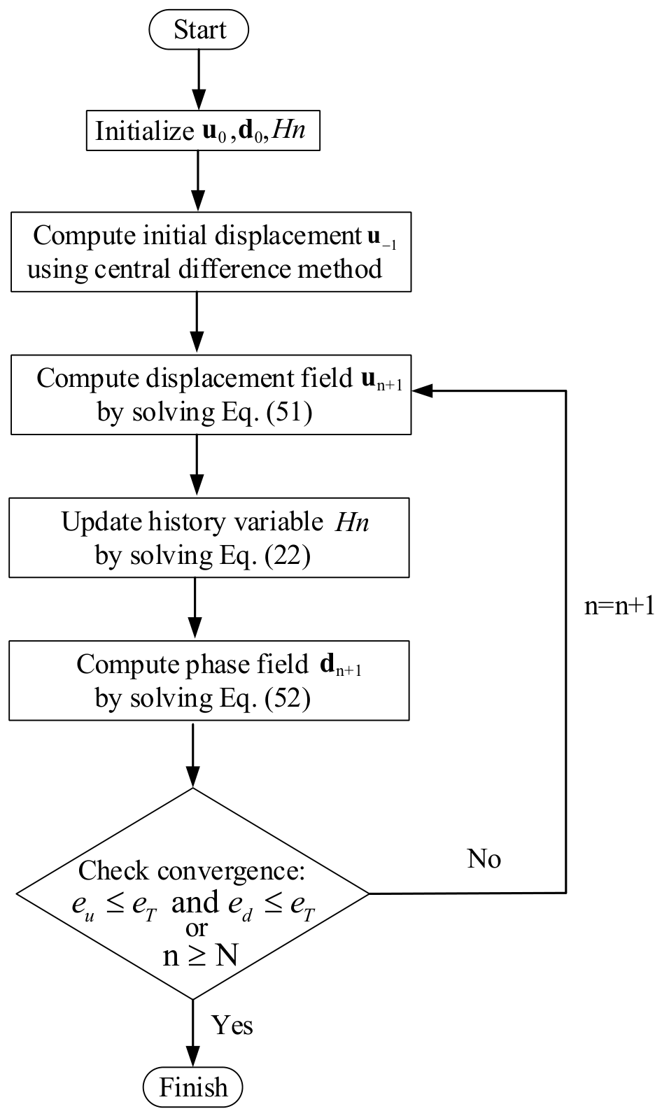
Flowchart of the staggered iteration algorithm for the dynamic fracture phase-field model.
2.1.2. Total Energy Functional
Consider a solid domain with a boundary embedded with an internal crack . The boundary is divided into two parts, and , on which Dirichlet and Neumann-type boundary conditions are imposed, respectively. According to Griffith’s theory [50], the total potential energy of the cracked body can be obtained from the elastic strain energy and the fracture energy, and can be expressed as:
where is the elastic energy, is the energy required to create new cracks, is the strain energy density function, is the strain tensor, is the displacement vector, and is the critical energy release rate.
Based on the regularized formulation introduced in the Section 2.1.1, the potential energy function Equation (8) can be rewritten as:
where is the initial free energy density function, and g(d) denotes the degradation function, defined as follows, to model the gradual reduction in the material stiffness.
where k is a sufficiently small parameter to avoid singularity.
For the undamaged, homogeneous, isotropic linear elastic material, the free energy density function can be defined as:
where and are the Lamé constants, and tr(.) represents the trace of the second-order tensor.
Crack initiation and propagation in isotropic solids are assumed to be induced exclusively by tensile loading. Therefore, the elastic strain energy density function can be split into tensile and compressive components. Then, the elastic strain energy density function can be rewritten as:
where is the elastic density caused by tension, and is the elastic density caused by compression. The symbol denotes the MaCaulay bracket, shown as .
Besides the elastic strain energy and fracture energy, the potential energy due to external forces is:
Building structures are subjected to various dynamic loads, such as earthquakes and explosions. Therefore, the effect of inertial forces on material performance cannot be ignored. For such dynamic problems, the kinetic energy of the system is:
where ρ is the material mass density.
2.1.3. Governing Equations
By taking the variation in Equations (9), (15) and (16) with respect to the displacement and phase fields, and applying the energy balance equation and the principle of virtual work, we can derive the coupled governing equations.
For the displacement field, the governing equations and boundary conditions can be expressed as:
where is the Cauchy stress tensor.
For the phase field, Miehe et al. [51] introduced an artificial viscosity coefficient related to the rate of phase-field change into the model; the governing equations can then be expressed as:
To avoid crack healing during compression or unloading, the local history strain energy function is introduced to store the maximum elastic strain energy during the damage process:
The damage evolution function can then be expressed as:
2.2. Crack Model of Variable Stiffness Composite Materials
2.2.1. Modeling the VSCs
With the rapid advancement in modern FRP manufacturing technologies, variable stiffness composites (VSCs) can now be fabricated using curved fiber placement techniques. In contrast to traditional straight-fiber composites, the fiber orientation in VSCs varies continuously. VSCs can be modeled using three main approaches: discrete fiber angle representation, direct stiffness modeling, and fiber path description [52]. Among these approaches, fiber path description can guarantee fiber continuity by employing a mathematical formulation to generate curved fiber trajectories. Moreover, this approach requires only a few fiber path parameters as design variables, thereby simplifying the optimization process and offering designers straightforward insights. Therefore, this modeling methodology is adopted in this study. Here, a periodic form of linear orientation fiber path is generalized. The master curve of the fiber trajectory is shown in Figure 1a in [49], and the fiber orientation can be expressed as [49]:
where x and y represent the global coordinates, is the local reference coordinates, is the angle between the local and global axes, T0 and T1 represent the trajectory orientations in the center and edge , respectively, and L0 is the reference length. Consequently, a VSC lamina can be uniquely defined by using a three-parameters method . Considering the rotational symmetry of the fiber paths, the values of , T0, and T1 are considered only within the range [0, 90°]. Since (the unit of the angle) is used throughout the study, it will be omitted for convenience and conciseness in the remaining parts.
The transformation between the two coordinate systems is given by the following expression:
The geometric relationship between the reference fiber path (master curve) and fiber orientation is
The master curve can be defined by performing integration for both sides of Equation (26) with considering the boundary condition . Then, the fiber paths over the whole VSC panel can be extended by shifting the master curve along the reference direction , as shown in Figure 1b in [49].
2.2.2. Dynamic Fracture Phase-Field Model for VSC
This subsection develops a dynamic fracture phase-field model for VSCs, based on the phase-field theory introduced in Section 2.1. The phase field can be divided into matrix and fiber components for the FRP materials. By introducing a second-order tensor into Equation (7) [53], the crack surface density function for FRP materials can be derived as
where is the second-order structural tensor, which can be defined as [49]
where is the fiber orientation for FRP materials, is the penalty parameter, and denotes the dyadic product of two vectors. Two structural tensors for fiber failure and matrix failure are respectively introduced as
where is perpendicular to , denotes the second-order tensor for the matrix part, and represents the second-order tensor for the fiber part. The crack surface density function can then be rewritten as
where and denote the damage of matrix and fiber failure, respectively, and and denote the length scale parameters of the matrix and fiber, respectively.
Similarly, the free energy density function described by Equation (12) can be decomposed into matrix and fiber parts [49]
where denotes the energy associated with matrix deformation, and represents the energy contributed by fiber deformation. The and can be simplified as
where is the strain vector in the principal material coordinate, and it can be defined as
where T is the transformation matrix and can be written as
In Equation (33), and can be written as [54]
where , , , . , and are the longitudinal, transverse, and shear moduli, respectively. and are the Poisson’s ratio.
Following the methodology of Equation (13), the energy components corresponding to the matrix and the fiber in anisotropic materials can be decomposed into positive and negative parts, respectively:
where g is the degradation function as defined in Equation (12) and can be rewritten as
The terms , , , and are given by
The positive/negative decomposition of the principal strain vector is
with
Hence, the governing equations for the displacement field remain unchanged, as shown in Equations (17)–(19), while the governing equation for the phase field can be rewritten as
In Equation (43), the driving forces can be defined as and . For fiber failure, it is mostly driven by tension and compression, and the shear deformation can be neglected. However, for the matrix failure, the energy due to shear deformation cannot be overlooked. Since the transverse fracture energy is not equivalent to the in-plane shear fracture energy , the driving force should be expressed using a mixed-mode formulation.
where
3. Numerical Implementation
By employing the finite element method (FEM), the displacement field u and the phase field d can be approximated by
where ue and de are the element nodal value vectors of the displacement field and phase field, respectively; and are the acceleration and the rate of change in the phase field, respectively; and are the element nodal value vectors corresponding to and , Nu and Nd are interpolation matrices containing the shape functions for displacement and phase fields. Here, the same shape function is used for the displacement and phase fields. For clarity and without loss of generality, the phase field is not divided into matrix and fiber components for the composite materials in this section, unlike the approach taken in the previous subsection.
The strain vector and the gradient vector of the phase field within the element are obtained as
where Bu is derivative of shape functions with respect to displacement, and Bd is derivative of the phase field.
The residual vector for the displacement and phase fields can be expressed as
It is seen that the governing system is a coupled problem. Some numerical approaches have been employed by researchers to obtain the solution. To improve the convergence speed and stability, a staggered algorithm with iterations is adopted in this paper. In a staggered algorithm, there are several iterations for each small load increment. The procedures of the staggered iteration algorithm are as follows: First, the displacement field at step n + 1 is calculated using the phase field from step n; then, the history variable is updated using the displacement field ; finally, the phase field is obtained using the updated fields , , and boundary conditions. The process of the staggered iteration algorithm at displacement–incremental step n + 1 is shown in the following equations
The stiffness matrix of phase field and displacement field at the element level can be respectively calculated by
where C is the elastic stiffness matrix. The corresponding force vectors are given by
It is worth noting that in the alternating iteration algorithm, the order of calculating the phase field and the displacement field can be reversed without affecting the results.
In summary, we outlined the computational flow of the staggered iteration algorithm for the dynamic fracture phase-field model, as shown in Figure 1.
To obtain reliable results with the phase-field method, the computational domain requires very fine discretization, which leads to substantial computational time. Hence, the codes in this study are implemented in a fully vectorized manner by using array operations through MATLAB (R2018b) software to enhance efficiency.
4. Model Validation with Experimental Results
To validate the reliability of the proposed dynamic fracture phase-field model and its corresponding program, the numerical results need to be compared with experimental data. It should be noted that experimental data for dynamic crack propagation in VSCs are scarce. Therefore, we validate the proposed model using CSC specimens, for which reliable experimental data are available in the literature. Here, the dynamic crack propagation in a CSC laminate with a single-edge crack under tensile loading is simulated using the proposed model and compared with the experimental results.
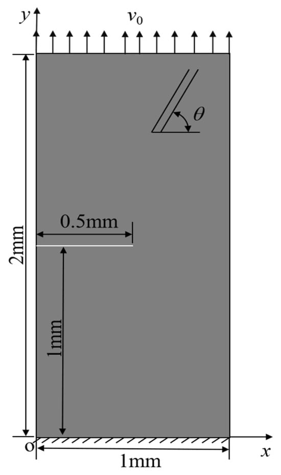
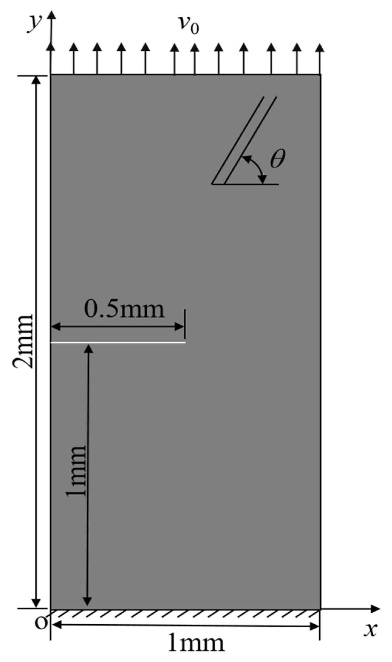
The schematic diagram of the single-edge cracked CSC lamina is shown in Figure 2, and the material properties are shown in Table 1 [10]. The velocity load is applied on the top edge of the plate along the y-axis direction, while the bottom edge is fixed. The fiber orientation angle with respect to the x-axis is denoted as . The velocity load is expressed as
Figure 2.
Schematic diagram of the single-edge cracked constant-stiffness composite lamina.
Table 1.
Material properties.
In this study, quadrilateral four-node elements were employed for the finite element discretization. The smallest element size in the mesh was 0.005 mm. The phase-field length scale parameter was set to l0 = 0.03 mm for both the matrix and the fiber. The ratio of element size to length scale is 1/6. This value is considerably smaller than the recommended upper bound of 1/2 reported in reference [30], ensuring that the simulation results are not affected by mesh size. The time step used in the simulation was s, which is smaller than the critical time step 5 × 10⁻¹⁰ s for the central difference method.
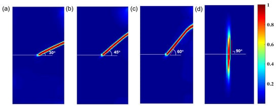
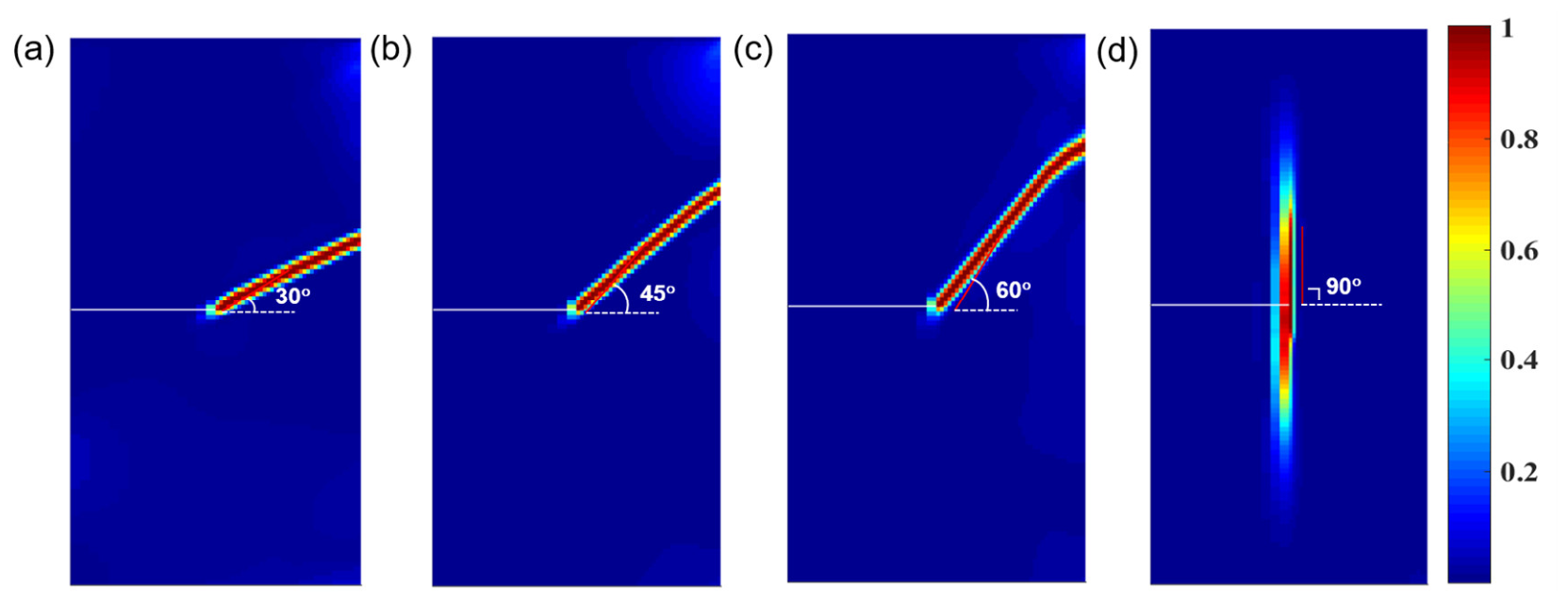
Simulations were performed on constant-stiffness composite plates with a single-edge crack at fiber orientations of 30°, 45°, 60°, and 90°, under the same impact loading. The resulting crack propagation paths for each case are shown in the upper row of Figure 3. Since no fiber damage was observed during the simulations, only the matrix crack propagation contours are presented. It can be seen that the crack propagation paths are parallel to the fiber orientations for all cases. Additionally, the experimental results reported by Cahill et al. [10] are employed to validate the model. As can be seen from Figure 5 in [10], for different fiber angles the experimentally observed cracks all propagate along the fiber direction, i.e., the crack propagation is parallel to the fiber path. As shown in Figure 3, the numerical results show that for different fiber angles the cracks consistently propagate parallel to the fiber path. The simulation results from the present model show good agreement with the experimental results, demonstrating the proposed model’s capability in simulating fracture evolutions and revealing the failure mechanism in constant-stiffness composite lamina.
Figure 3.
Crack propagation paths for the single-edge cracked composite laminae with fiber orientations (a) 30°, (b) 45°, (c) 60°, and (d) 90°.
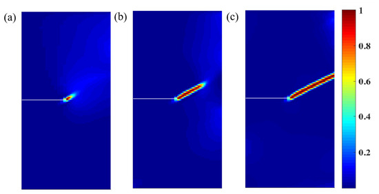
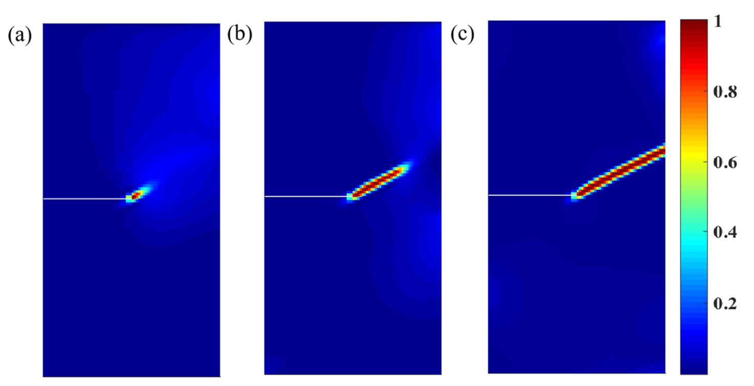
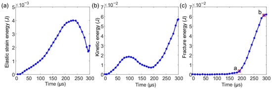
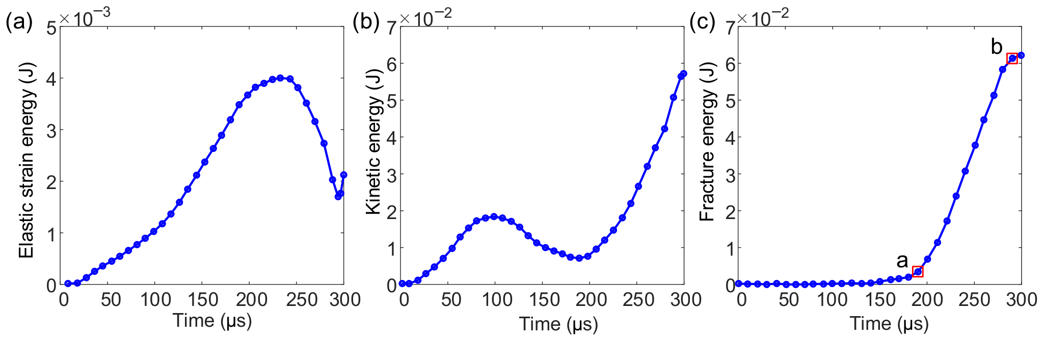
Furthermore, the proposed model was employed to analyze crack propagation in CSCs, using a fiber orientation of 30◦ as an example. The crack propagation paths at different time steps are shown in Figure 4. It can be observed that the crack first nucleates at the pre-crack tip and then propagates along the fiber direction until it reaches the right edge of the lamina, resulting in complete fracture. Since crack propagation involves energy conversion, this study conducted an in-depth analysis of the fracture process from the energy perspective. The curves of elastic strain energy, kinetic energy, and fracture energy versus time are shown in Figure 5.
Figure 4.
Crack propagation path for fiber orientation of 30°: (a) 200 μs, (b) 240 μs, and (c) 290 μs.
Figure 5.
System energy for fiber orientation of 30°: (a) elastic strain energy, (b) kinetic energy, and (c) fracture energy.
In Figure 5a, the elastic strain energy initially increases, reaches a maximum, and then gradually decreases. This reduction occurs because part of the elastic strain energy is converted into the fracture energy required for material failure, to the point of complete fracture. In Figure 5b, the kinetic energy of the system under external loading continues to increase until the structural load-bearing limit is reached. Once crack initiation begins, the kinetic energy begins to decrease, providing additional energy for fracture propagation. However, as the external load continues to input energy into the system, the overall kinetic energy again increases. In Figure 5c, the fracture energy initially increases slowly. Upon reaching point a, crack initiation occurs at the right tip of the pre-crack. Subsequently, as the crack propagates, the fracture energy rises sharply until it reaches point b, where the lamina is completely fractured. After the plate is fully damaged, the fracture energy remains nearly constant. Furthermore, comparing the vertical axis values in the three figures reveals that the magnitude of the fracture energy exceeds that of the elastic strain energy, with the remainder supplied by the kinetic energy of the system. This indicates that the inertia induced by the external loading significantly affects the fracture behavior of fiber-reinforced composites.
This analysis demonstrates the proposed model’s ability to accurately simulate crack propagation in composites, with particular consideration of inertial effects under dynamic loading conditions.
5. Investigating Dynamic Crack Propagation in VSCs
In composites employed for structural strengthening, building components, and 3D printing, internal defects such as voids and cracks are inevitably present. Investigating the influence of these defects on the fracture behavior of composites is crucial for improving the mechanical properties of both the composite materials and the overall structure. This section systematically examines the crack propagation behavior of composites under several different defect configurations.
5.1. Tensile Failure of Single-Edge Cracked VSCs
To investigate the influence of design variables , T0, and T1 of the fiber trajectory on crack propagation, dynamic crack propagation was analyzed in single-edge crack VSC laminae. The geometry of the single-edge cracked VSC laminae is identical to that shown in Figure 2, and the fiber trajectory follows a curvilinear path. All material parameters, load magnitude, and time step remain same as those specified in Section 4.
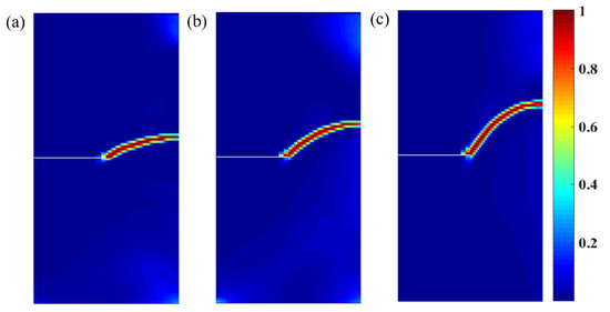
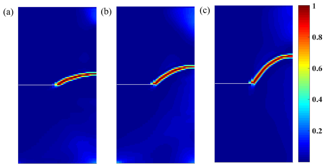
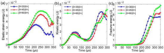
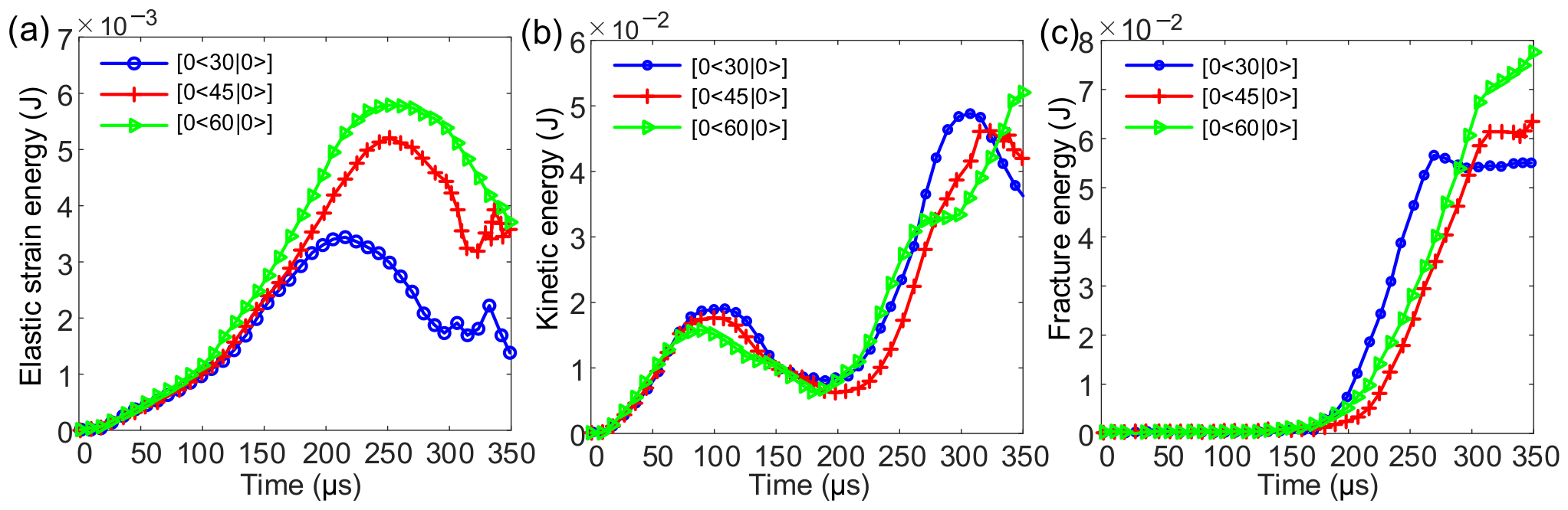
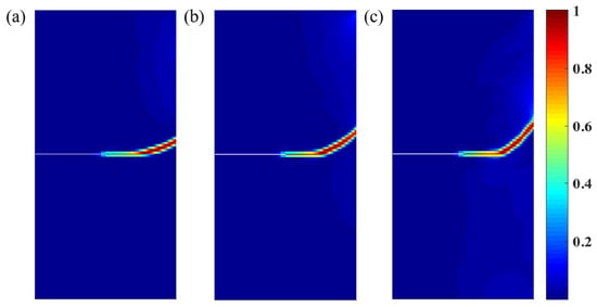
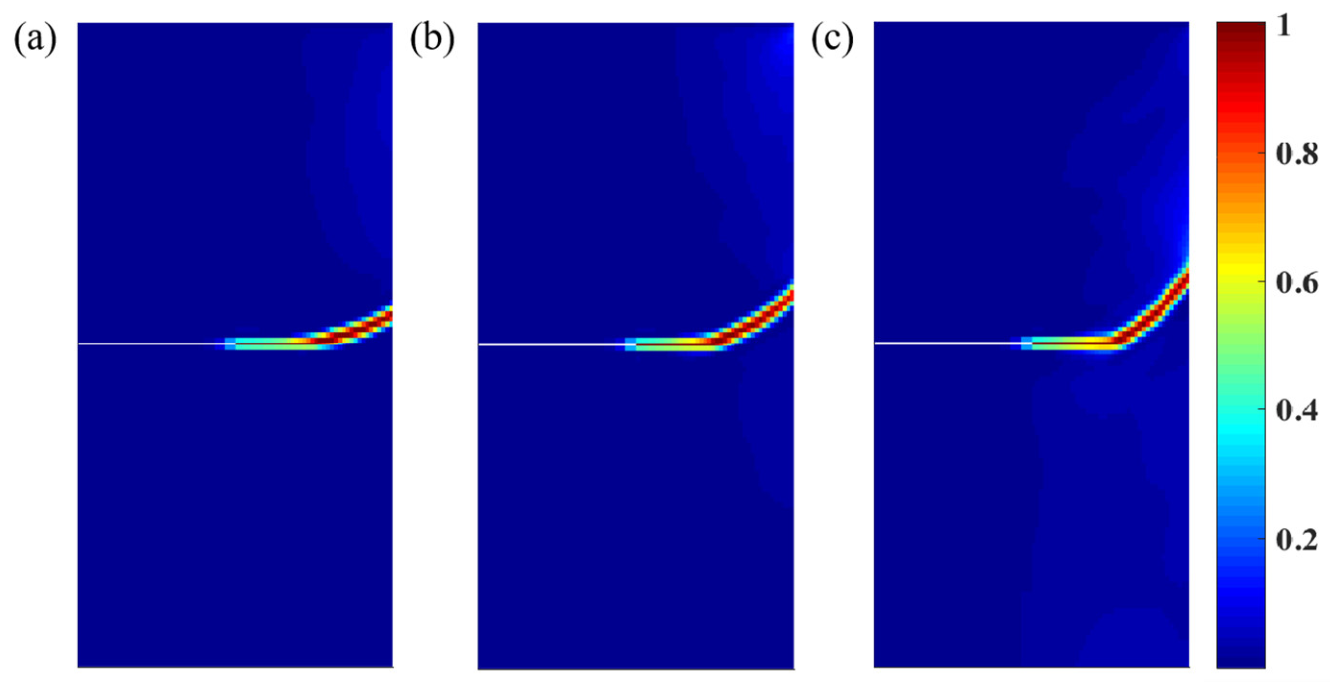
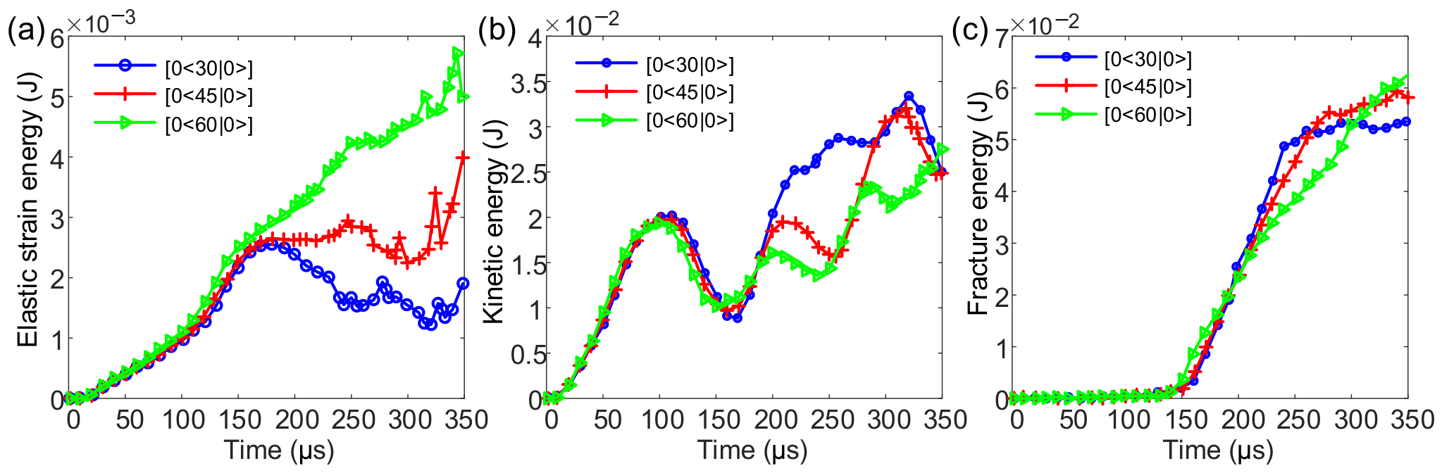
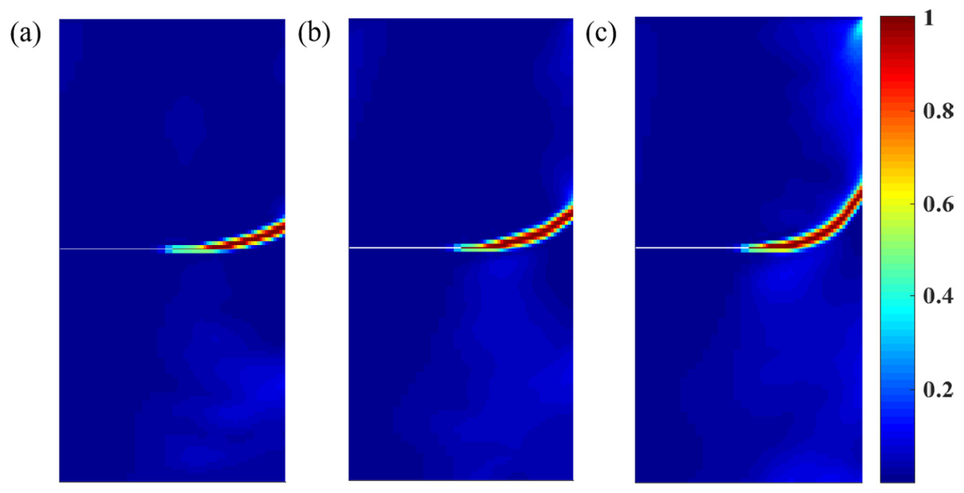
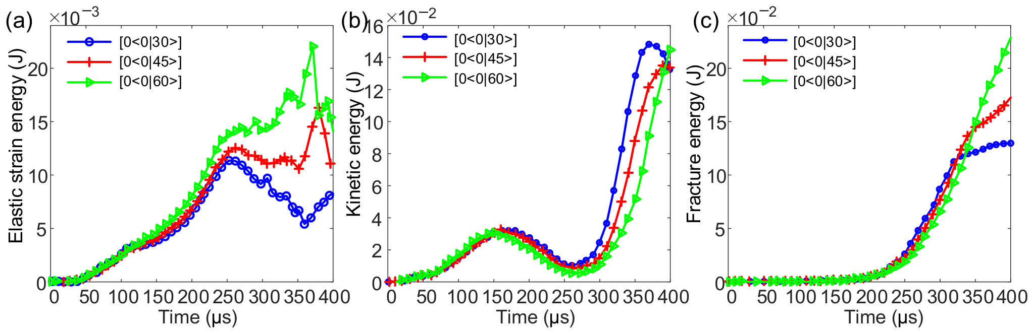
First, to investigate the influence of parameter T0 on crack propagation, we set and T1 = 0, and let T0 take values of 30°, 45°, and 60°. The results are shown in Figure 6. It can be observed that the crack propagation paths are no longer straight but consistently follow the fiber directions. The curves of elastic strain energy, kinetic energy, and fracture energy for the VSCs with different T0 are presented in Figure 7. It can be seen that during the fracture process from 180 μs to 260 μs, the case with T0 = 30° exhibits the lowest elastic strain energy and the highest fracture energy, while its kinetic energy remains comparable to that of the T0 = 45° and 60° cases. After complete fracture, as minimal kinetic energy conversion to fracture energy is required, the kinetic energy for T0 = 30° exceeds that of the other two cases. Furthermore, the VSCs with T0 = 30° fractures earlier than those with T0 = 45° and 60°, and requires more energy during the initial fracture stage. After the VSCs with T0 = 30° is fully fractured, the fracture energy for T0 = 45° and 60° continues to increase, surpassing that of the case with T0 = 30° until reaching their respective complete fracture energies. At complete failure, the fracture energies are 5.5 × 10⁻² J, 6.3 × 10⁻² J, and 7.5 × 10⁻² J for T0 = 30°, 45°, and 60°, respectively. The fracture energy at complete failure increases with T0. This demonstrates that variations in fiber orientations lead to differences in energy dissipation during fracture. The slight increase in fracture energy after complete fracture is attributed to the continued expansion of the crack surface due to the sustained application of the external load.
Figure 6.
The crack propagation paths in VSCs [0 ⟨T0|0⟩] with T0 = 30°, 45°, and 60°: (a) [0 ⟨30|0⟩], (b) [0 ⟨45|0⟩], and (c) [0 ⟨60|0⟩]. [ ⟨T0|T1⟩] denotes the fiber trajectory, where is the angle between the local and global axes, and T0 and T1 represent the trajectory orientations in the center and edge, respectively.
Figure 7.
System energy for the VSCs [0 ⟨T0|0⟩] with T0 = 30°, 45°, and 60°: (a) elastic strain energy, (b) kinetic energy, and (c) fracture energy.
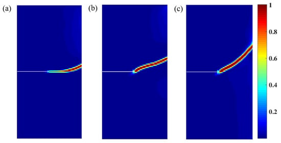
Subsequently, to investigate the influence of parameter T1 on crack propagation, we set , T0 = 0, and let T1 take values of 30°, 45°, and 60°. Interestingly, for all cases with different T1, the cracks in the VSC laminate initially extend transversely before propagating along the fiber path, as illustrated in Figure 8. This phenomenon occurs due to the relatively low magnitude of the applied velocity load.
Figure 8.
The crack propagation paths in VSCs [0⟨0|T1⟩] with T1 = 30°, 45°, and 60°: (a) [0 ⟨0|30⟩], (b) [0 ⟨0|45⟩], and (c) [0 ⟨0|60⟩]. [ ⟨T0|T1⟩] denotes the fiber trajectory, where is the angle between the local and global axes, and T0 and T1 represent the trajectory orientations in the center and edge, respectively.
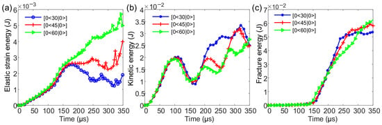
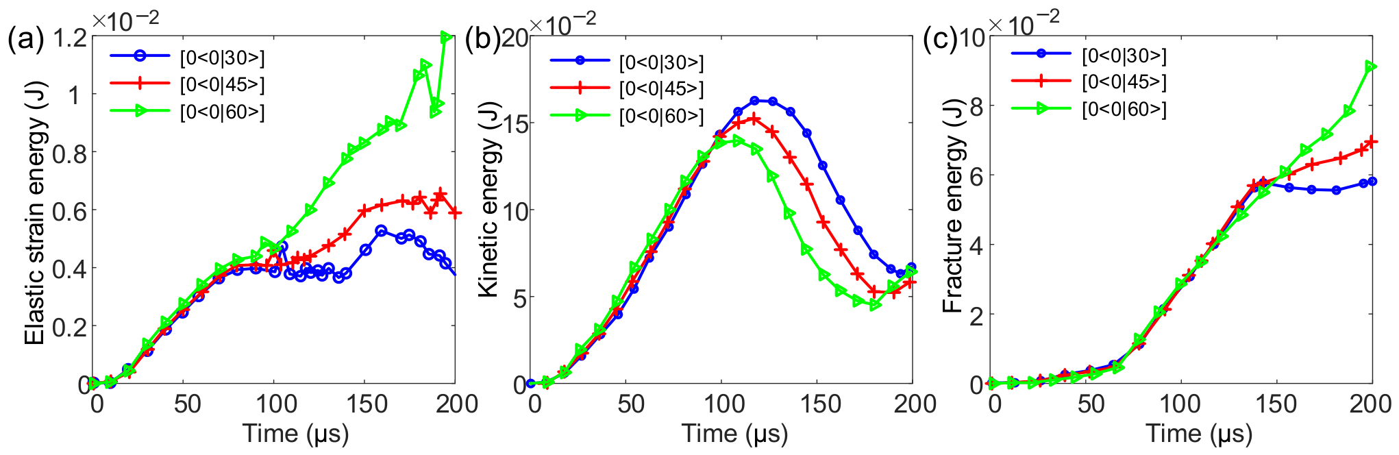
The curves of elastic strain energy, kinetic energy, and fracture energy for the VSCs with different T1 are shown in Figure 9. Although the energy trends in the early fracture stage are generally consistent with those observed in Figure 7, it can be observed that significant changes occur in the elastic strain energy and kinetic energy during the later stage, whereas the fracture energy trend remains consistent. These results demonstrate the notable influence of the design variable T1 of the fiber orientation on the evolution of elastic strain energy and kinetic energy. Notably, for T1 = 60°, the elastic strain energy beyond 200 μs substantially exceeds that of the other cases, while the corresponding kinetic energy is lower, indicating that more kinetic energy is converted into fracture energy after this time point.
Figure 9.
System energy for the VSCs [0 ⟨0|T1⟩] with T1 = 30°, 45°, and 60°: (a) elastic strain energy, (b) kinetic energy, and (c) fracture energy.
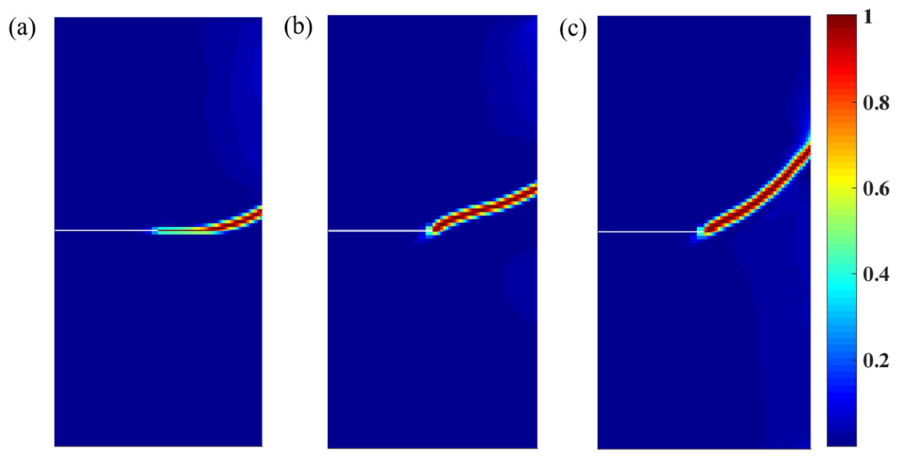
Regarding the phenomenon that the crack propagation initially undergoes a period of transverse extension before following the fiber path, the maximum velocity increased from 2 mm/s to 5 mm/s while maintaining the same time required to reach the maximum velocity. The velocity load is defined as
The resulting crack propagation paths are shown in Figure 10. It can be seen that the extent of transverse crack propagation is significantly reduced, and the crack propagation paths follow the fiber directions.
Figure 10.
The crack propagation paths in VSCs [0 ⟨0|T1⟩] with T1 = 30°, 45°, and 60° when velocity load changed: (a) [0 ⟨0|30⟩], (b) [0 ⟨0|45⟩], and (c) [0 ⟨0|60⟩]. [ ⟨T0|T1⟩] denotes the fiber trajectory, where is the angle between the local and global axes, and T0 and T1 represent the trajectory orientations in the center and edge, respectively.
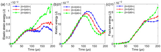
As observed from the energy–time curves in Figure 11 under the modified velocity loading, the time required for complete fracture is significantly reduced, and the magnitudes of both elastic strain energy and kinetic energy increase significantly. At complete failure, the fracture energies are 5.8 × 10⁻² J, 7.0 × 10⁻² J, and 9.1 × 10⁻² J for T1 = 30°, 45°, and 60°, respectively. The fracture energy at complete failure increases with T1. However, the trends in elastic strain energy and kinetic energy remain similar to those in Figure 9, further confirming that parameter T1 influences the evolution of elastic strain energy and kinetic energy.
Figure 11.
System energy for the VSCs [0 ⟨0|T1⟩] with T1 = 30°, 45°, and 60° when velocity load changed: (a) elastic strain energy, (b) kinetic energy, and (c) fracture energy.
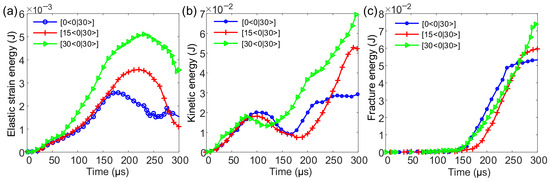
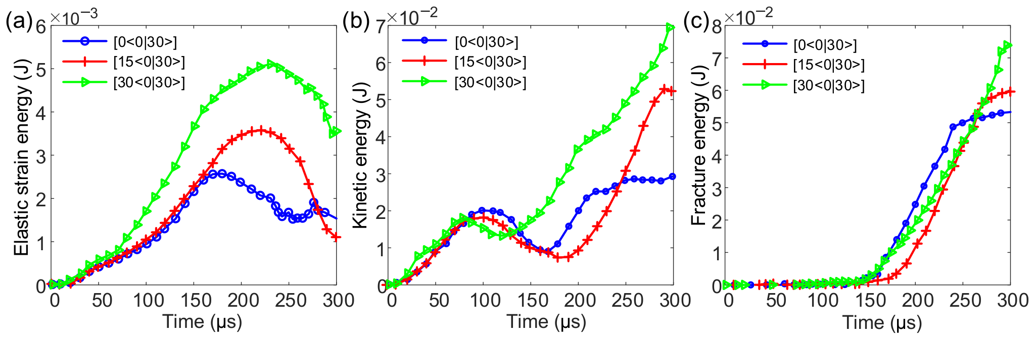
Finally, to investigate the influence of parameter on crack propagation, we set T0 = 0, T1 = 30°, and let take values of 0°, 15°, and 30°. The corresponding crack propagation paths are shown in Figure 12. It can be observed that when , transverse crack extension occurs, which is consistent with the previously discussed effect of T1 on crack propagation. For the other cases, the crack clearly propagates along the direction of the curved fibers.
Figure 12.
The crack propagation paths in VSCs [ ⟨0|30⟩] with = 0, 15°, and 30°: (a) [0 ⟨0|30⟩] (b), [15 ⟨0|30⟩], and (c) [30 ⟨0|30⟩]. [ ⟨T0|T1⟩] denotes the fiber trajectory, where is the angle between the local and global axes, T0 and T1 represent the trajectory orientations in the center and edge, respectively.
The curves of elastic strain energy, kinetic energy, and fracture energy for the VSCs with different are shown in Figure 13. When , the elastic strain energy, kinetic energy, and total energy required for complete fracture are significantly higher than those at 0° and 15°. This indicates that crack propagation is more difficult in this case and more energy is required to reach the strength limit. Consequently, the fiber-reinforced composite plate exhibits superior mechanical performance in this configuration.
Figure 13.
System energy for the VSCs [ ⟨0|30⟩] with = 0, 15°, and 30°: (a) elastic strain energy, (b) kinetic energy, and (c) fracture energy.
These results demonstrate that the design variables , T0, and T1 of the fiber trajectory significantly influence the fracture behavior of VSCs. Through appropriate selection of these parameter combinations, it is possible to fabricate composite materials with superior mechanical properties.
5.2. Fracture Behavior of Open-Hole VSCs
In this section, a rectangular VSC lamina with a width of 1 mm, a height of 2 mm, and a circular hole of radius 0.1 mm located at its center is considered. The origin O of the Cartesian coordinate system is placed at the lower-left corner of the specimen, with the x-axis extending horizontally to the right and the y-axis extending vertically upward. The bottom edge of the specimen is fully fixed, and a uniformly distributed velocity load is applied on the top edge in the positive y-direction. The material parameters, load magnitude, time-step, and other settings remain consistent with those defined in Section 4.
Since the effects of the design variables , T0, and T1 of the fiber trajectory on fracture crack propagation in VSCs have already been systematically discussed in Section 5.1, this section focuses only on the effect of T1 on the fracture behavior of the VSCs.
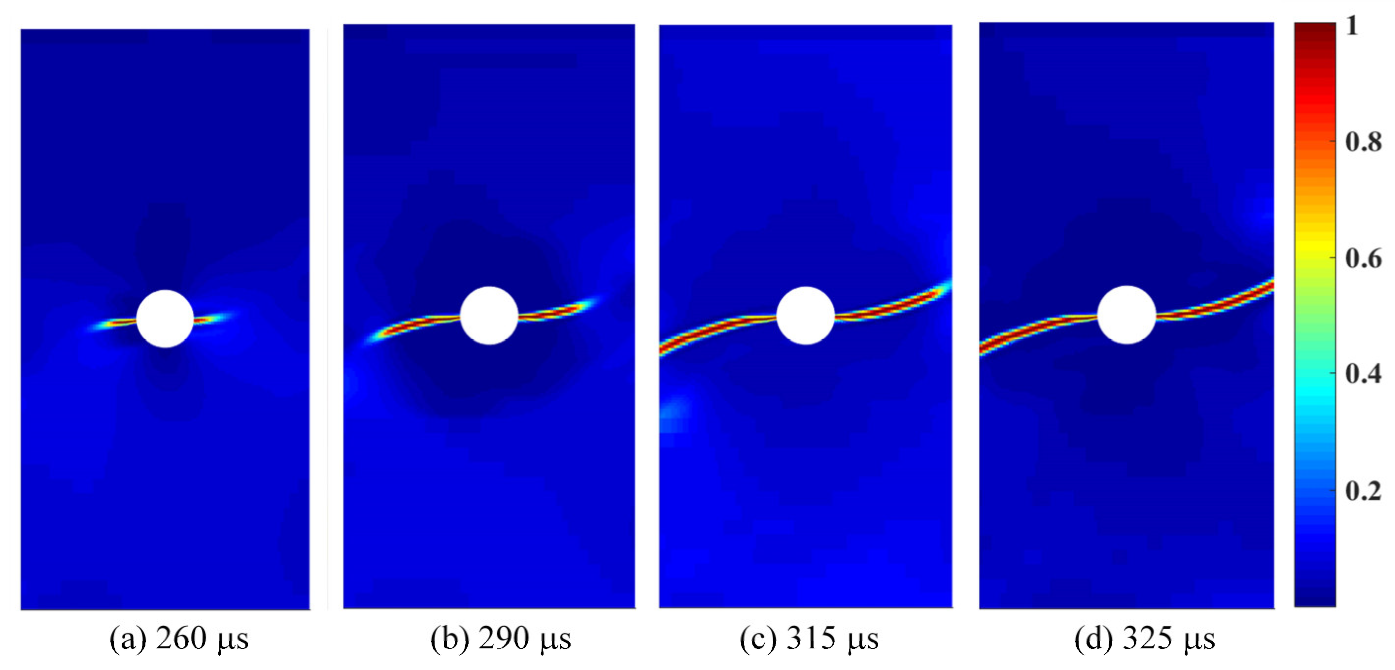
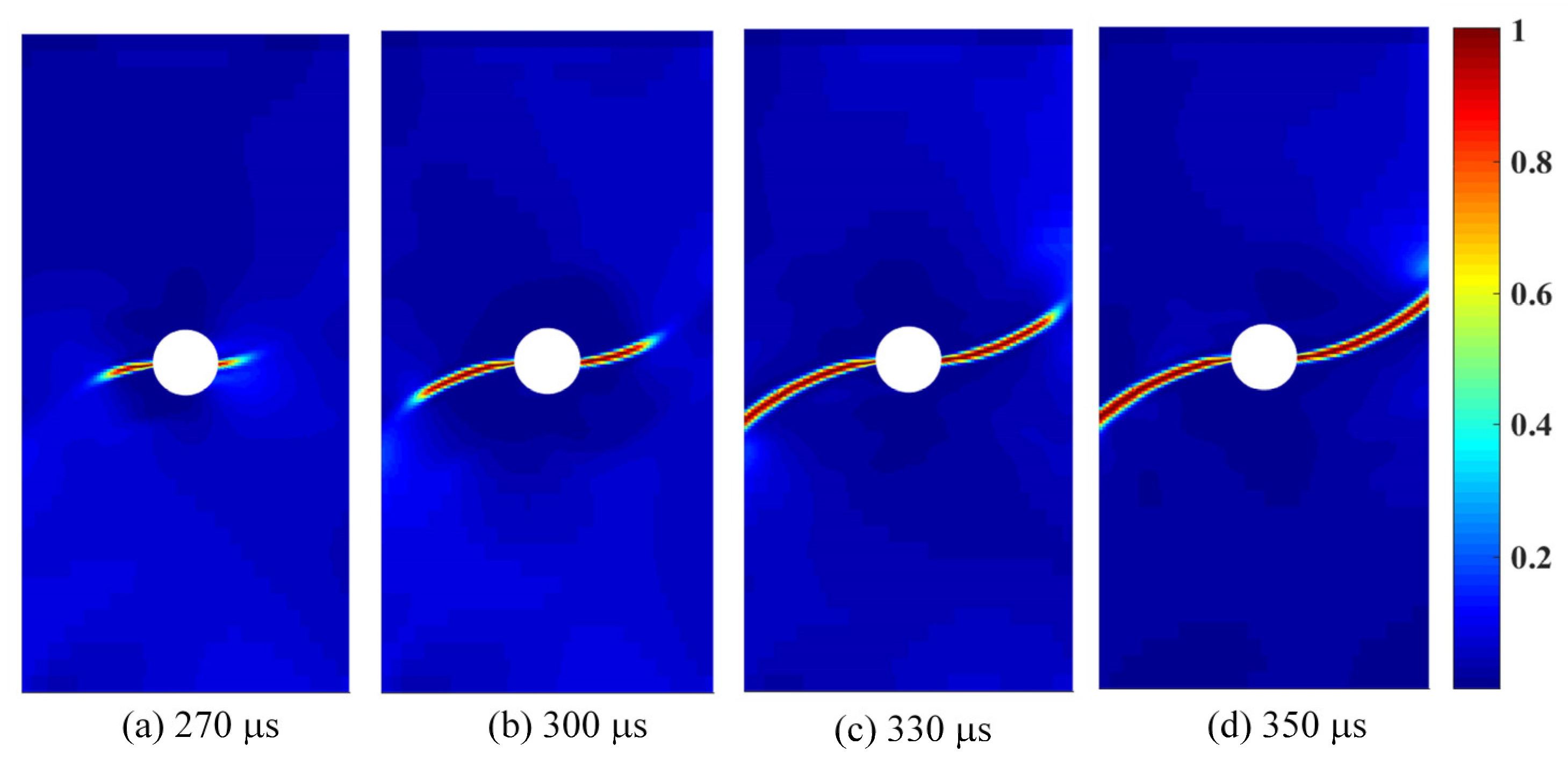
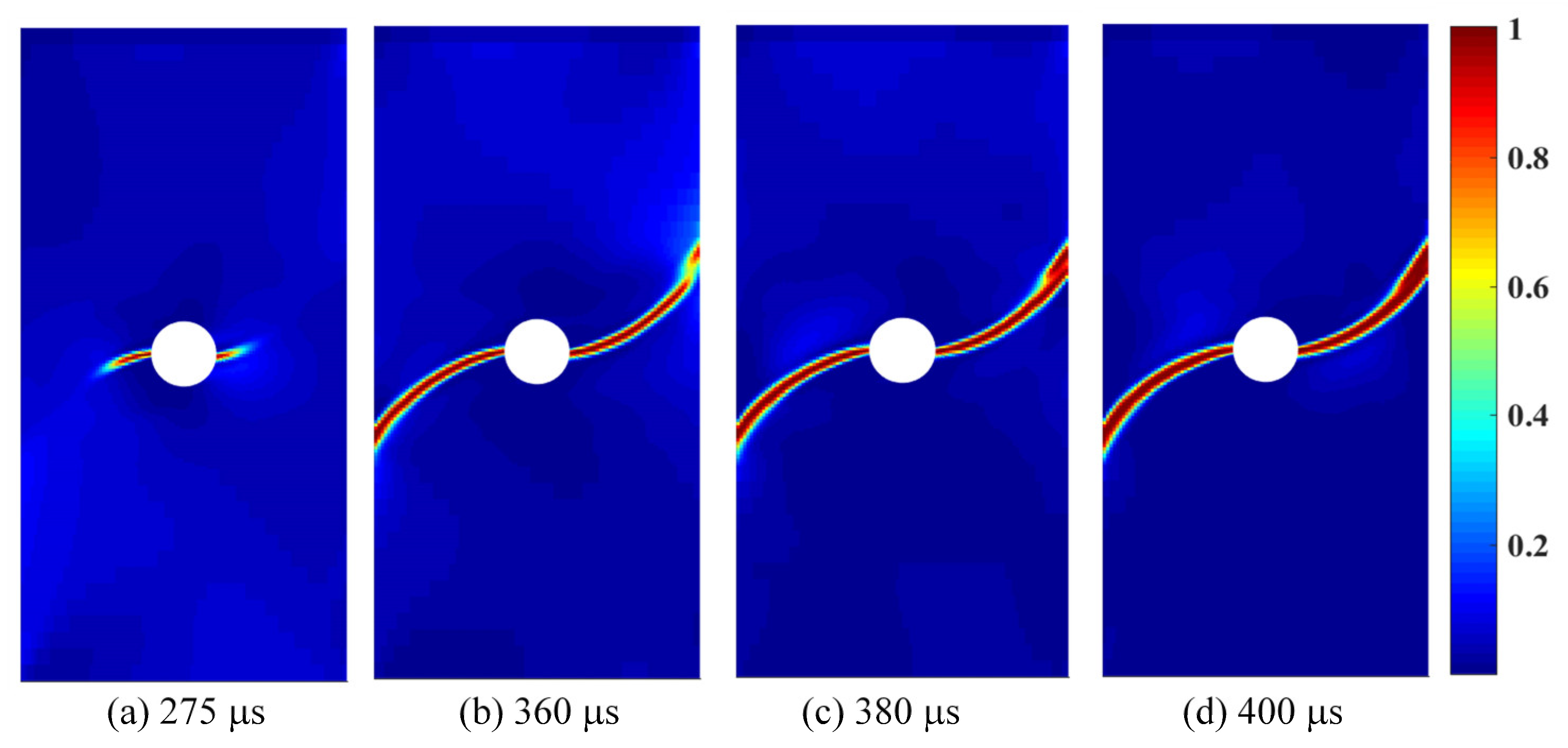
The crack propagation paths for the open-hole VSCs with T1 = 30°, 45°, and 60° are shown in Figure 14, Figure 15 and Figure 16, respectively. It can be seen that, in all cases, the cracks initiate on both the left and right sides of the central circular hole, where the stress first concentrates and the stress is the first to reach the material’s ultimate strength. The crack propagation paths subsequently propagate along the fiber path toward the left and right edges of the VSC lamina. However, it is evident in all cases that the delayed initiation and propagation of the right-side crack relative to the left-side crack result from asymmetric mesh discretization around the circular hole. Nevertheless, the crack propagation results for VSCs with different fiber configurations show that the primary crack consistently propagates along the fiber trajectories. Furthermore, for T1 = 60°, a secondary crack is clearly observed initiating at the right edge at 360 μs and propagating backward along the fiber path toward the hole. After the main crack reaches the edge, its fracture surface gradually widens and eventually coalesces with the secondary crack. We attribute this behavior to the fact that the fiber curvature in this case is the largest among all considered configurations. The highly curved fiber paths lead to a significant redistribution of stresses along the plate’s side edge.
Figure 14.
The crack propagation paths for fiber orientation [0 ⟨0|30⟩].
Figure 15.
The crack propagation paths for fiber orientation [0 ⟨0|45⟩].
Figure 16.
The crack propagation paths for fiber orientation [0 ⟨0|60⟩].
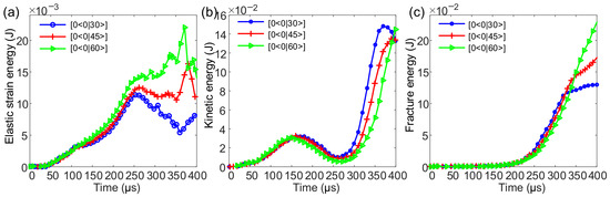
The curves of elastic strain energy, kinetic energy, and fracture energy for the open-hole VSCs with different T1 are shown in Figure 17. It can be observed that both elastic strain energy and kinetic energy are converted into the fracture energy required for crack propagation. As the fiber angle increases, the total energy required for complete fracture also increases. This is because a larger fiber angle results in a smaller angle between the loading direction and the fiber orientation, thereby enhancing the material’s load-bearing capacity and requiring more energy to induce fracture.
Figure 17.
System energy for the open-hole VSCs [0 ⟨0| T1⟩] with T1 = 30°, 45°, and 60°: (a) elastic strain energy, (b) kinetic energy, and (c) fracture energy.
5.3. Fracture Behavior of Porous VSCs
When subjected to external impact, porous composite materials absorb and dissipate shock energy through deformation, compression, or fracture of their pores, thereby mitigating the shock’s effect on the structure. This section investigates the influence of different pore arrangements on impact-induced crack propagation in porous VSCs. The fiber paths are also optimized for structures with varying pore distributions. The findings provide valuable guidance for the fabrication of porous composite materials.
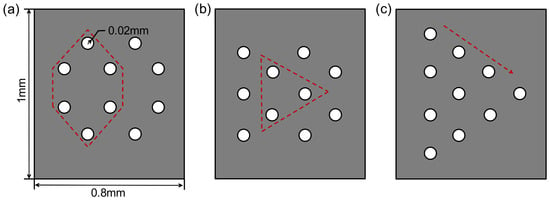
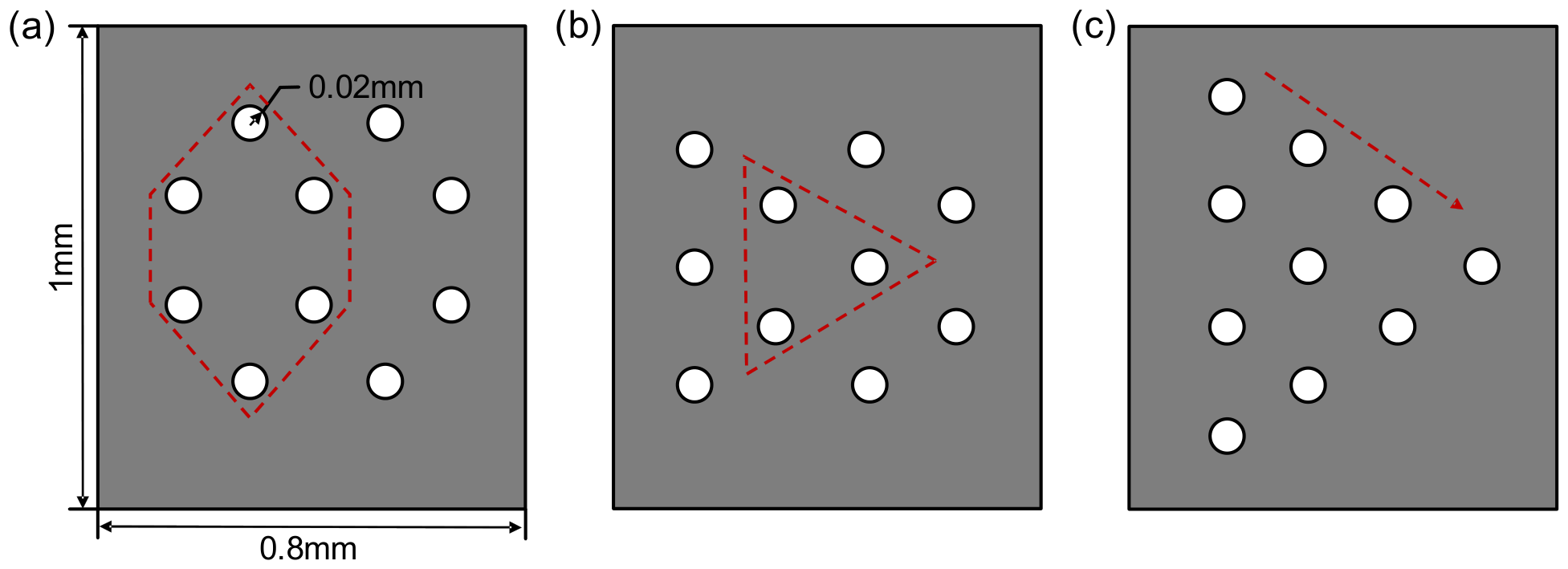
Three pore configurations were designed: a hexagonal array, a triangular array, and a tapered distribution with a uniform porosity of 1.5%, as shown in Figure 18. All models had an overall dimension of 0.8 mm × 1 mm and pore radius of 0.02 mm. Quadrilateral four-node elements with a minimum mesh size of 0.004 mm is employed to discretize the VSCs. The phase-field length scale was set to for both matrix and fiber, and the time step was s. The material parameters were as follows: Young’s moduli GPa, GPa, shear modulus GPa, Poisson’s ratio , critical energy release rates , , , and density kg/m3. The fiber path of the VSCs were defined by three parameters [0 <60|0>]. For all three configurations, the right side was fixed while the same impact load was applied to the left side, and the load is expressed as
Figure 18.
Three pore configurations of the VSCs: (a) hexagonal array, (b) triangular array, and (c) tapered distribution.
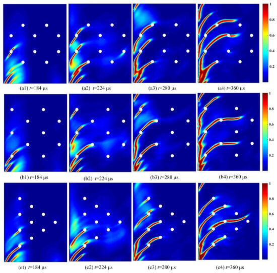
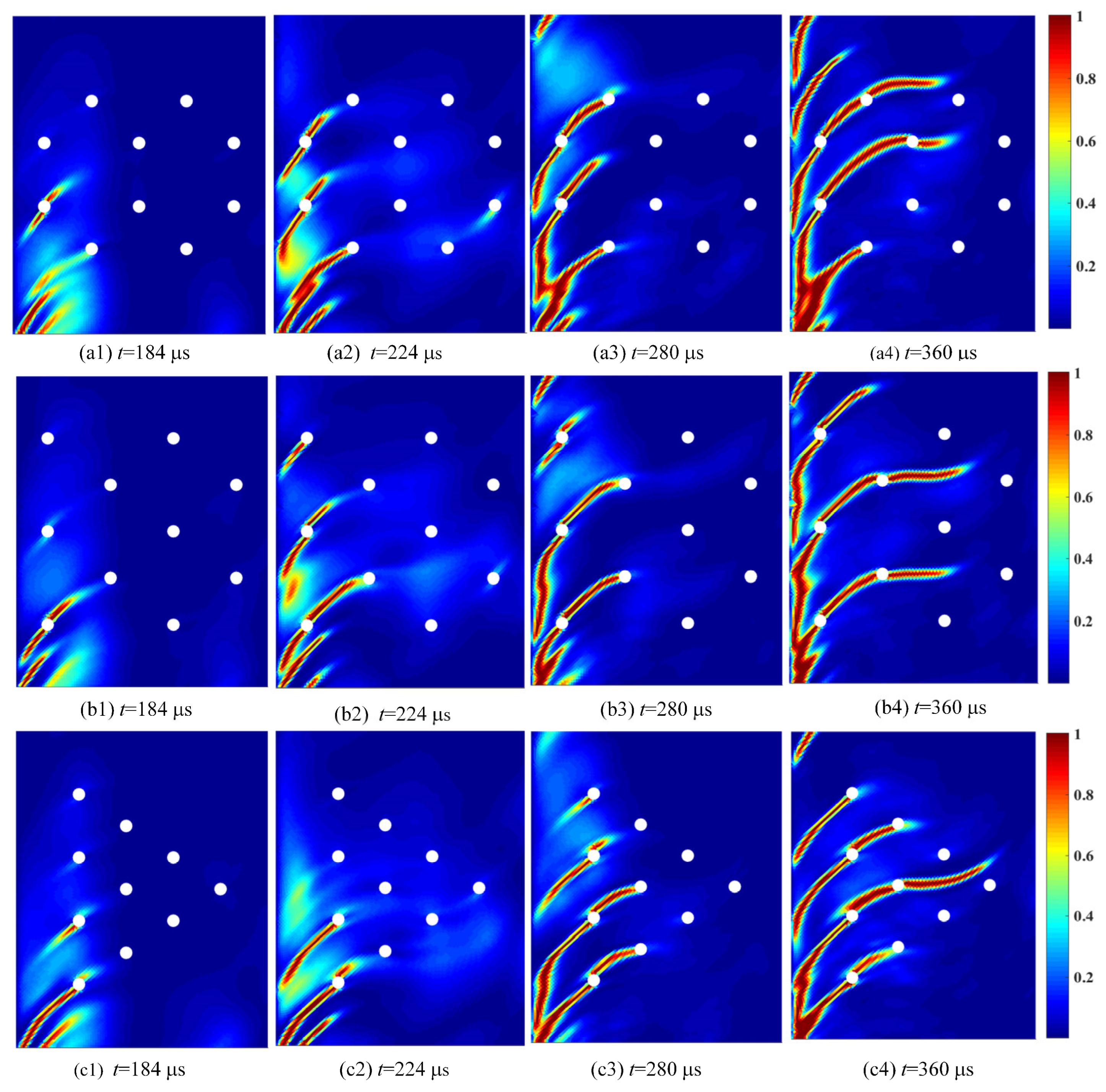
The crack propagation evolution for the three pore arrangements is illustrated in Figure 19. Overall, all three configurations exhibit consistent crack evolution behavior: stress concentration occurs near the pores, and cracks propagate through the pores and along the curved fiber path. At 184 μs, cracks initiate at the bottom pore of the first column and propagate at a 60° inclination, vertically penetrating the first pore. At 224 μs, cracks emerge around the first column of pores in both the hexagonal and triangular arrays, whereas only one additional crack appears in the tapered arrangement. At 280 μs, the cracks propagate along the fiber path to the second column of pores. The pre-existing cracks continuously expand their fracture surfaces, and new cracks appear at the top of the structure in the hexagonal and triangular arrays. At 360 μs, the crack propagates transversely through the second column of pores and reaches the third column. Owing to differences in pore distribution, the crack fully penetrates the third column of pores in the hexagonal and tapered arrays, whereas in the triangular array, it stops midway between two pores. The initially formed cracks continue to expand and coalesce into larger fracture surfaces. Moreover, a longitudinal comparison of the three cases reveals that the tapered arrangement exhibits slower crack evolution in the early stage, whereas in the triangular array, the curved fiber orientation deflects the crack away from the third column of pores, effectively mitigating stress concentration around the pores. The hexagonal array shows intermediate performance.
Figure 19.
The crack propagation paths of three pore configurations VSCs for fiber orientation [0 ⟨60|0⟩]: (a): hexagonal array; (b): triangular array; (c): tapered distribution.
These results demonstrate that a rational design of fiber orientation can guide cracks away from pores, thereby optimizing the material’s impact response. Consequently, multiple sets of curved fiber angles are designed for the three pore configurations, and their crack propagation behaviors are analyzed individually. Subsequently, to identify effective approaches for optimizing fracture paths, we conduct detailed discussions on several cases with remarkably low stress concentration around internal pores.
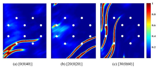
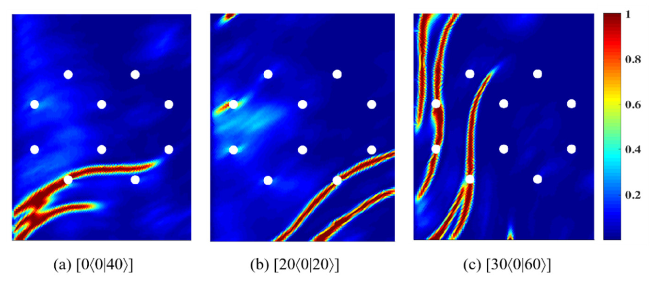
For the hexagonal pore array configuration, crack propagation paths for three fiber paths [0 ⟨0|40⟩], [20 ⟨0|20⟩], and [30 ⟨0|60⟩] are shown in Figure 20. When the fiber path is [0 ⟨0|40⟩], stress concentration occurs near the lower part of the structure, and the crack propagates along the fiber direction. Notably, no fracture occurs around the pores in the middle-upper region, demonstrating a significant improvement compared to the [0 ⟨60|0⟩] case. For the VSCs with fiber path [20 ⟨0|20⟩], cracks first initiate at the lower-right corner and subsequently form at the upper-left corner. However, no significant stress concentration is observed around most pores, indicating considerable improvement over the [0 ⟨60|0⟩] configuration. For the fiber path [30 ⟨0|60⟩], the crack follows a steeper propagation path toward the upper part of the structure, while no crack occurs at the right side. This case shows a clear improvement in the right side of the structure compared to the [0 ⟨60|0⟩] case.
Figure 20.
The crack propagation paths of VSCs for fiber orientation (a) [0 ⟨0|40⟩], (b) [20 ⟨0|20⟩], and (c) [30 ⟨0|60⟩].
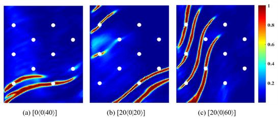
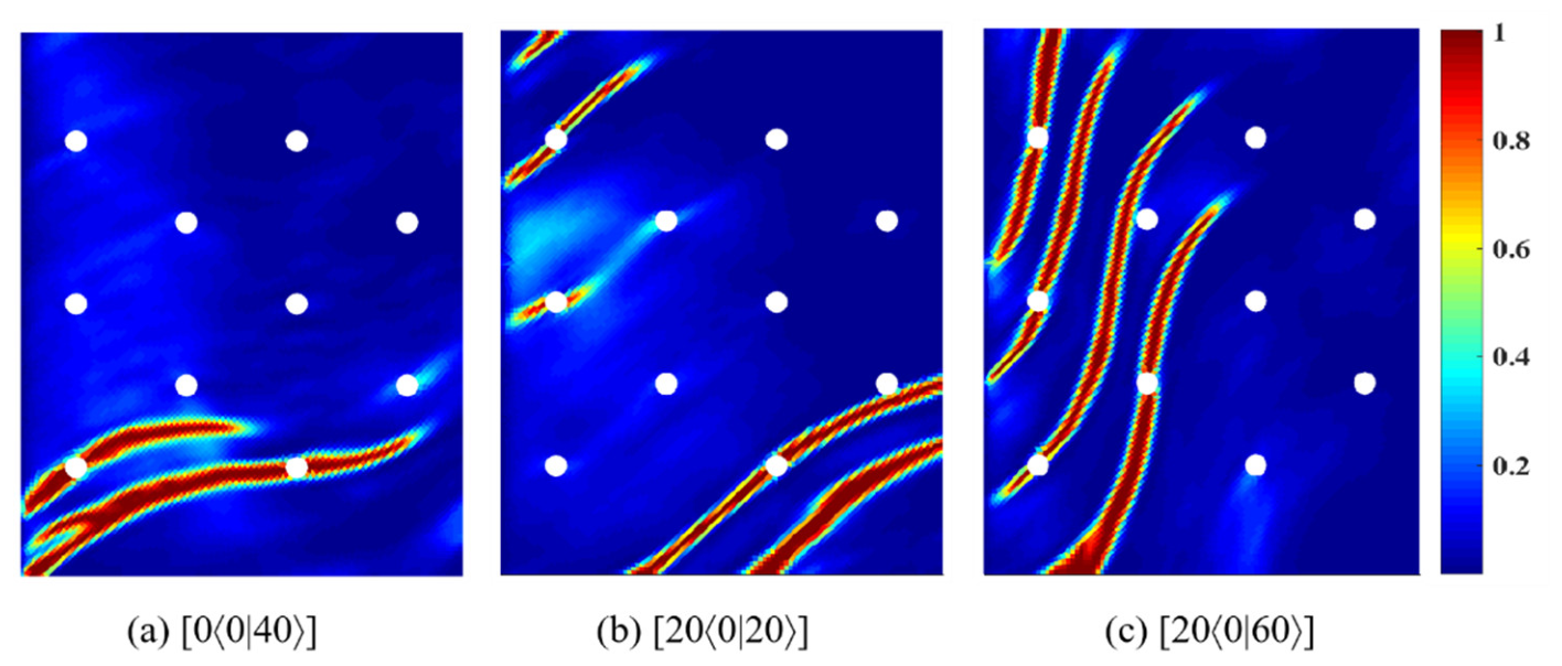
For the triangular array configuration, crack propagation paths for three fiber paths [0 ⟨0|40⟩], [20 ⟨0|20⟩], and [20 ⟨0|60⟩] are shown in Figure 21. The overall crack evolution in the triangular array is generally similar to that in the hexagonal array. However, with the fiber path [20 ⟨0|20⟩], crack evolution in the upper-left region of the triangular array progresses significantly faster than in the hexagonal case. Under identical conditions, the hexagonal array exhibits superior performance.
Figure 21.
The crack propagation paths of VSCs for fiber orientation (a) [0 ⟨0|40⟩], (b) [20 ⟨0|20⟩], and (c) [20 ⟨0|60⟩].
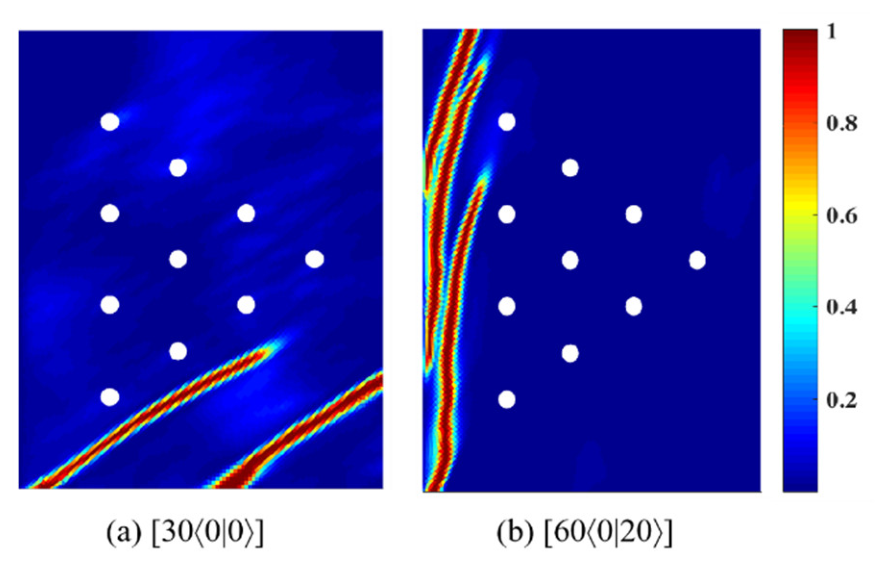
For the tapered distribution configuration, crack propagation paths for two fiber paths [30 ⟨0|0⟩] and [60 ⟨0|20⟩] are shown in Figure 22. When the fiber path is [30 ⟨0|0⟩], the crack propagates at a 30° angle below the pore array. With the fiber path [60 ⟨0|20⟩], crack extension occurs on the left side of the pore array. In both cases, the crack paths avoid passing through the pores. Compared to the previous tapered distribution results with the fiber path [0 ⟨60|0⟩], the stress concentration around the pores is significantly reduced, demonstrating a remarkable optimization effect.
Figure 22.
The crack propagation paths of VSCs for fiber orientation (a) [30 ⟨0|0⟩] and (b) [60 ⟨0|20⟩].
The optimization results of fiber paths in the hexagonal, triangular, and tapered pore configurations show that modifying the fiber placement angle can alter the crack propagation path and mitigate the stress concentration around the pores. This is because tailoring the fiber placement trajectory enables adjustment of the relationship between the local stress state and the fiber orientation in the composite. Since cracks in fiber-reinforced composites tend to propagate along the fiber direction or the fiber–matrix interface, adjusting the angle between the principal stress direction and the fiber path can effectively influence the crack initiation timing, initiation location, and propagation direction. For example, when the fiber path is appropriately designed to bypass pore regions, the crack propagates along the fiber direction and circumvents the pores instead of passing through them, thereby significantly mitigating the stress concentration and suppressing the premature formation of local damage around the pores. Therefore, optimizing the fiber placement trajectory can effectively mitigate stress concentration around pores at different locations within the structure, thereby enhancing the impact resistance of the perforated structure.
6. Conclusions
In this study, a dynamic phase-field model was established to analyze fracture behavior of fiber-reinforced composites under dynamic loading. The model was first validated against experimental results for single-edge cracked FRC laminae. The influence of three design variables governing the fiber orientation and internal defects on the fracture behavior of VSCs was systematically investigated. The fracture behavior of VSCs with different pore arrangements was further studied, and the corresponding fiber paths were optimized. The main conclusions are as follows:
- (1)
- The coupled phase-field and displacement-field solution procedure, which considers the inertial effects due to load acceleration, is feasible and reliable. The proposed model can effectively capture the fracture behavior of CSCs and VSCs under dynamic loading.
- (2)
- The crack propagation paths in VSCs are curvilinear and consistently follow the fiber directions. By properly designing the fiber trajectory, the stress can be redistributed from the weak to the strong regions, and the stiffness distribution of VSCs can be adjusted, thereby, enhancing the overall stiffness and load-bearing capacity.
- (3)
- Optimizing the design variables enables the crack propagation path to be steered away from the pores in open-hole or porous VSCs, effectively mitigating stress concentration and reducing the impact of external shocks. This strategy enables the design of high-performance composites with superior impact resistance and load-bearing capacity.
This work provides fundamental insights into the design and optimization of composites, particularly VSC laminates, and lays a theoretical foundation for their practical application in building engineering, especially in scenarios requiring enhanced impact resistance and load-bearing capacity, such as structural strengthening and seismic resistance.
Author Contributions
Conceptualization, C.X. and Y.Z.; methodology, K.X.; software, K.X.; validation, C.X., T.G. and Y.Z.; formal analysis, K.X.; investigation, C.X. and T.G.; resources, C.X. and Y.Z.; data curation, K.X.; writing—original draft preparation, C.X. and K.X.; writing—review and editing, C.X. and Y.Z.; visualization, C.X., T.G. and K.X.; supervision, Y.Z.; project administration, Y.Z.; funding acquisition, C.X., T.G. and Y.Z. All authors have read and agreed to the published version of the manuscript.
Funding
This study was financially supported by the Jiangsu Open University Fourteenth Five-Year Plan Project (Grant No. 2023XK019), National Natural Science Foundation of China (Grant No. 12272182), Natural Science Foundation of Jiangsu Province (Grant No. BK20230966), Special Funding Project of China Postdoctoral Science Foundation (Grant No. 2023TQ0105), and Natural Science Foundation of the Jiangsu Higher Education Institutions of China (Grant No. 23KJB130003).
Data Availability Statement
The original contributions presented in the study are included in the article; further inquiries can be directed to the corresponding author.
Conflicts of Interest
Author Keran Xu was employed by the company Nanjing Fiberglass Research & Design Institute Co., Ltd. The remaining authors declare that the research was conducted in the absence of any commercial or financial relationships that could be construed as potential conflicts of interest.
References
- Mrazova, M. Advanced composite materials of the future in aerospace industry. Incas Bull. 2013, 5, 139–150. [Google Scholar] [CrossRef] [Scilit]
- Bhong, M.; Khan, T.K.H.; Devade, K.; Krishna, B.V.; Sura, S.; Eftikhaar, H.K.; Thethi, H.P.; Gupta, N. Review of composite materials and applications. Mater. Today Proc. 2023, 2214–7853. [Google Scholar] [CrossRef] [Scilit]
- Asyraf, M.R.M.; Ilyas, R.A.; Sapuan, S.M.; Harussani, M.M.; Hariz, H.M.; Aiman, J.M.; Baitaba, D.M.; Sanjay, M.R.; Ishak, M.R.; Norkhairunnisa, M. Advanced composite in aerospace applications: Opportunities, challenges, and future perspective. In Advanced Composites in Aerospace Engineering Applications; Springer Nature Link: Berlin/Heidelberg, Germany, 2022; pp. 471–498. [Google Scholar]
- Bachmann, J.; Hidalgo, C.; Bricout, S. Environmental analysis of innovative sustainable composites with potential use in aviation sector—A life cycle assessment review. Sci. China Technol. Sci. 2017, 60, 1301–1317. [Google Scholar] [CrossRef] [Scilit]
- Kabir, S.M.F.; Mathur, K.; Seyam, A.-F.M. A critical review on 3D printed continuous fiber-reinforced composites: History, mechanism, materials and properties. Compos. Struct. 2020, 232, 111476. [Google Scholar] [CrossRef] [Scilit]
- Dirk, H.J.A.L.; Ward, C.; Potter, K.D. The engineering aspects of automated prepreg layup: History, present and future. Compos. Part B-Eng. 2012, 43, 997–1009. [Google Scholar] [CrossRef] [Scilit]
- Malakhov, A.V.; Polilov, A.N.; Zhang, J.; Hou, Z.; Tian, X. A modeling method of continuous fiber paths for additive manufacturing (3D printing) of variable stiffness composite structures. Appl. Compos. Mater. 2020, 27, 185–208. [Google Scholar] [CrossRef] [Scilit]
- Gürdal, Z.; Tatting, B.F.; Wu, C.K. Variable stiffness composite panels: Effects of stiffness variation on the in-plane and buckling response. Compos. Part A Appl. Sci. Manuf. 2008, 39, 911–922. [Google Scholar] [CrossRef] [Scilit]
- Milazzo, A.; Oliveri, V. Investigation of buckling characteristics of cracked variable stiffness composite plates by an eXtended Ritz approach. Thin Wall. Struct. 2021, 163, 107750. [Google Scholar] [CrossRef] [Scilit]
- Cahill, L.M.A.; Natarajan, S.; Bordas, S.P.A.; O’Higgins, R.M.; McCarthy, C.T. An experimental/numerical investigation into the main driving force for crack propagation in uni-directional fibre-reinforced composite laminae. Compos. Struct. 2014, 107, 119–130. [Google Scholar]
- Ghosh, G.; Biswas, D.; Bhattacharyya, R. Advancements in multiscale modeling of damage in composite materials: A comprehensive review. Compos. Part B-Eng. 2025, 307, 112819. [Google Scholar] [CrossRef] [Scilit]
- Cheng, Z.-Q.; Liu, H.; Tan, W. Advanced computational modelling of composite materials. Eng. Fract. Mech. 2024, 305, 110120. [Google Scholar] [CrossRef] [Scilit]
- Roth, S.-N.; Léger, P.; Soulaïmani, A. A combined XFEM–damage mechanics approach for concrete crack propagation. Comput. Methods Appl. Mech. Eng. 2015, 283, 923–955. [Google Scholar] [CrossRef] [Scilit]
- Colombo, D. An implicit geometrical approach to level sets update for 3D non planar X-FEM crack propagation. Comput. Methods Appl. Mech. Eng. 2012, 237, 39–50. [Google Scholar] [CrossRef] [Scilit]
- Ashari, S.E.; Mohammadi, S. Delamination analysis of composites by new orthotropic bimaterial extended finite element method. Int. J. Numer. Methods Eng. 2011, 86, 1507–1543. [Google Scholar] [CrossRef] [Scilit]
- Huynh, D.B.P.; Belytschko, T. The extended finite element method for fracture in composite materials. Int. J. Numer. Methods Eng. 2009, 77, 214–239. [Google Scholar]
- Xu, D.; Liu, Z.; Liu, X.; Zeng, Q.; Zhuang, Z. Modeling of dynamic crack branching by enhanced extended finite element method. Comput. Mech. 2014, 54, 489–502. [Google Scholar] [CrossRef] [Scilit]
- Yin, B.B.; Zhang, L.W. Phase field method for simulating the brittle fracture of fiber reinforced composites. Eng. Fract. Mech. 2019, 211, 321–340. [Google Scholar] [CrossRef] [Scilit]
- Amiri, F.; Millán, D.; Arroyo, M.; Silani, M.; Rabczuk, T. Fourth order phase-field model for local max-ent approximants applied to crack propagation. Comput. Methods Appl. Mech. Eng. 2016, 312, 254–275. [Google Scholar]
- Aifantis, E.C. On the role of gradients in the localization of deformation and fracture. Int. J. Eng. Sci. 1992, 30, 1279–1299. [Google Scholar] [CrossRef] [Scilit]
- Bažant, Z.P.; Belytschko, T.B. Wave propagation in a strain-softening bar: Exact solution. J. Eng. Mech. 1985, 111, 381–389. [Google Scholar]
- Yin, B.B.; Sun, W.K.; Zhang, Y.; Liew, K.M. Modeling via peridynamics for large deformation and progressive fracture of hyperelastic materials. Comput. Methods Appl. Mech. Eng. 2023, 403, 115739. [Google Scholar] [CrossRef] [Scilit]
- Alessi, R.; Freddi, F. Failure and complex crack patterns in hybrid laminates: A phase-field approach. Compos. Part B-Eng. 2019, 179, 107256. [Google Scholar] [CrossRef] [Scilit]
- Borden, M.J.; Verhoosel, C.V.; Scott, M.A.; Hughes, T.J.R.; Landis, C.M. A phase-field description of dynamic brittle fracture. Comput. Methods Appl. Mech. Eng. 2012, 217, 77–95. [Google Scholar] [CrossRef] [Scilit]
- Zhang, Y.; Guo, J.; Shu, Z.; Guan, Y.; Ademiloye, A.S. Fracture simulation of fiber reinforced composite panels with holes. Compos. Struct. 2025, 351, 118627. [Google Scholar]
- Gao, X.; Zhang, Y.; Liew, K.M. Electro-chemo-thermo-mechanical phase-field model for lithium penetration in solid electrolytes. Int. J. Mech. Sci. 2025, 307, 110913. [Google Scholar]
- Bourdin, B.; Francfort, G.A.; Marigo, J.-J. Numerical experiments in revisited brittle fracture. J. Mech. Phys. Solids 2000, 48, 797–826. [Google Scholar] [CrossRef] [Scilit]
- Wu, J.-Y. A geometrically regularized gradient-damage model with energetic equivalence. Comput. Methods Appl. Mech. Eng. 2018, 328, 612–637. [Google Scholar] [CrossRef] [Scilit]
- Pham, K.; Marigo, J.-J. From the onset of damage to rupture: Construction of responses with damage localization for a general class of gradient damage models. Contin. Mech. Thermodyn. 2013, 25, 147–171. [Google Scholar]
- Miehe, C.; Hofacker, M.; Welschinger, F. A phase field model for rate-independent crack propagation: Robust algorithmic implementation based on operator splits. Comput. Methods Appl. Mech. Eng. 2010, 199, 2765–2778. [Google Scholar] [CrossRef] [Scilit]
- Amor, H.; Marigo, J.-J.; Maurini, C. Regularized formulation of the variational brittle fracture with unilateral contact: Numerical experiments. J. Mech. Phys. Solids 2009, 57, 1209–1229. [Google Scholar] [CrossRef] [Scilit]
- Hofacker, M.; Miehe, C. A phase field model of dynamic fracture: Robust field updates for the analysis of complex crack patterns. Int. J. Numer. Methods Eng. 2013, 93, 276–301. [Google Scholar]
- Loew, P.J.; Peters, B.; Beex, L.A.A. Rate-dependent phase-field damage modeling of rubber and its experimental parameter identification. J. Mech. Phys. Solids 2019, 127, 266–294. [Google Scholar]
- Sridhar, A.; Keip, M.A. A phase-field model for anisotropic brittle fracturing of piezoelectric ceramics. Int. J. Fract. 2019, 220, 221–242. [Google Scholar] [CrossRef] [Scilit]
- Denli, F.A.; Gültekin, O.; Holzapfel, G.A.; Dal, H. A phase-field model for fracture of unidirectional fiber-reinforced polymer matrix composites. Comput. Mech. 2020, 65, 1149–1166. [Google Scholar] [CrossRef] [Scilit]
- Seleš, K.; Lesičar, T.; Tonković, Z.; Sorić, J. A residual control staggered solution scheme for the phase-field modeling of brittle fracture. Eng. Fract. Mech. 2019, 205, 370–386. [Google Scholar] [CrossRef] [Scilit]
- Li, B.; Maurini, C. Crack kinking in a variational phase-field model of brittle fracture with strongly anisotropic surface energy. J. Mech. Phys. Solids 2019, 125, 502–522. [Google Scholar] [CrossRef] [Scilit]
- Gültekin, O.; Dal, H.; Holzapfel, G.A. Numerical aspects of anisotropic failure in soft biological tissues favor energy-based criteria: A rate-dependent anisotropic crack phase-field model. Comput. Methods Appl. Mech. Eng. 2018, 331, 23–52. [Google Scholar] [PubMed]
- Gao, J.; Kedir, N.; Hernandez, J.A.; Gao, J.; Horn, T.; Kim, G.; Fezzaa, K.; Tallman, T.N.; Palmese, G.; Sterkenburg, R. Dynamic fracture of glass fiber-reinforced ductile polymer matrix composites and loading rate effect. Compos. Part B-Eng. 2022, 235, 109754. [Google Scholar] [CrossRef] [Scilit]
- Zarrinzadeh, H.; Kabir, M.Z.; Varvani-Farahani, A. Static and dynamic fracture analysis of 3D cracked orthotropic shells using XFEM method. Theor. Appl. Fract. Mech. 2020, 108, 102648. [Google Scholar] [CrossRef] [Scilit]
- Braun, M.; Ariza, M.P. New lattice models for dynamic fracture problems of anisotropic materials. Compos. Part B-Eng. 2019, 172, 760–768. [Google Scholar] [CrossRef] [Scilit]
- Nie, Y.; Parab, N.D.; Chu, J.-M.; Kim, G.; Sun, T.; Fezzaa, K.; Sterkenburg, R.; Chen, W.W. Dynamic crack propagation from a circular defect in a unidirectional carbon fiber reinforced plastic composite. J. Compos. Mater. 2018, 52, 3539–3547. [Google Scholar] [CrossRef] [Scilit]
- Esfarjani, A.A.; Nazari, M.B.; Bayat, S.H. Dynamic crack propagation in variable stiffness composite laminates under thermal shock. Theor. Appl. Fract. Mech. 2024, 130, 104325. [Google Scholar] [CrossRef] [Scilit]
- Li, D.M.; Featherston, C.A.; Wu, Z. An element-free study of variable stiffness composite plates with cutouts for enhanced buckling and post-buckling performance. Comput. Methods Appl. Mech. Eng. 2020, 371, 113314. [Google Scholar]
- Hao, P.; Yuan, X.; Liu, C.; Wang, B.; Liu, H.; Li, G.; Niu, F. An integrated framework of exact modeling, isogeometric analysis and optimization for variable-stiffness composite panels. Comput. Methods Appl. Mech. Eng. 2018, 339, 205–238. [Google Scholar] [CrossRef] [Scilit]
- Hirshikesh, A.; Natarajan, S.; Annabattula, R.K. Modeling crack propagation in variable stiffness composite laminates using the phase field method. Compos. Struct. 2019, 209, 424–433. [Google Scholar] [CrossRef] [Scilit]
- Li, H.; Wang, J. Modeling crack propagation in constant/variable stiffness composite laminates using X-VCFEM. Compu. Struct. 2025, 316, 107898. [Google Scholar] [CrossRef] [Scilit]
- Yu, Y.; Hou, C. Adaptive phase field model for constant/variable stiffness composite laminates based on remeshing technique. Compos. Struct. 2025, 372, 119620. [Google Scholar] [CrossRef] [Scilit]
- Pan, Z.Z.; Zhang, L.W.; Liew, K.M. A phase-field framework for failure modeling of variable stiffness composite laminae. Comput. Methods Appl. Mech. Eng. 2022, 388, 114192. [Google Scholar] [CrossRef] [Scilit]
- Griffith, A.A. VI. The phenomena of rupture and flow in solids. Philos. Trans. R Soc. Lond. Ser. A Contain. Pap. Math. Phys. Character 1921, 221, 163–198. [Google Scholar] [CrossRef] [Scilit]
- Miehe, C.; Welschinger, F.; Hofacker, M. Thermodynamically consistent phase-field models of fracture: Variational principles and multi-field FE implementations. Int. J. Numer. Methods Eng. 2010, 83, 1273–1311. [Google Scholar]
- Albazzan, M.A.; Harik, R.; Tatting, B.F.; Gürdal, Z. Efficient design optimization of nonconventional laminated composites using lamination parameters: A state of the art. Compos. Struct. 2019, 209, 362–374. [Google Scholar] [CrossRef] [Scilit]
- Pillai, U.; Triantafyllou, S.P.; Essa, Y.; de la Escalera, F.M. An anisotropic cohesive phase field model for quasi-brittle fractures in thin fibre-reinforced composites. Compos. Struct. 2020, 252, 112635. [Google Scholar]
- Dean, A.; Kumar, P.K.A.V.; Reinoso, J.; Gerendt, C.; Paggi, M.; Mahdi, E.; Rolfes, R. A multi phase-field fracture model for long fiber reinforced composites based on the puck theory of failure. Compos. Struct. 2020, 251, 112446. [Google Scholar] [CrossRef] [Scilit]

Disclaimer/Publisher’s Note: The statements, opinions and data contained in all publications are solely those of the individual author(s) and contributor(s) and not of MDPI and/or the editor(s). MDPI and/or the editor(s) disclaim responsibility for any injury to people or property resulting from any ideas, methods, instructions or products referred to in the content. |
© 2026 by the authors. Licensee MDPI, Basel, Switzerland. This article is an open access article distributed under the terms and conditions of the Creative Commons Attribution (CC BY) license.