


Abstract
Existing research on the axial compressive performance and size effect of carbon fiber-reinforced polymer (CFRP)-confined recycled aggregate concrete (RAC) short columns mainly relies on macroscopic experimental analysis, lacking research methods capable of reflecting the heterogeneous characteristics of materials and mesoscopic damage evolution mechanisms. Accordingly, a three-dimensional mesoscale finite element method was adopted in this study to establish a five-phase RAC mesoscopic model, including natural aggregates, old mortar, old interfacial transition zones (ITZs), new mortar, and new interfacial transition zones. Different from existing studies, predominantly based on macroscopic experiments or empirical models, this paper focuses on revealing the coupled effects of the recycled aggregate replacement ratio, the number of CFRP confinement layers, and specimen size. A total of 48 specimens were designed, covering four specimen sizes, four recycled coarse aggregate replacement ratios, and three CFRP confinement layers. The effects of these parameters on failure modes, stress–strain relationships, and size effect were systematically analyzed. The results indicate that the peak stress decreases significantly with the increase in the recycled coarse aggregate replacement ratio; the increase in CFRP layers markedly improves both the bearing capacity and post-peak bearing capacity retention rate; the ultimate stress generally declines as the specimen size increases, which highlights the pronounced size effect of CFRP-confined RAC short columns. Based on peak parameters and normalization analysis, a simplified stress–strain model was established: the goodness of fit R2 of the ascending branch is 0.98565, and the goodness of fit for the descending branch parameters are = 0.9655 and = 0.9350. Compared with existing models, the proposed model achieves a low prediction error of only 1.5–6.9%, demonstrating superior prediction accuracy. It can accurately describe the complete compressive process of CFRP-confined RAC short columns and provide a mesoscopic mechanistic basis for engineering design.
1. Introduction
With the rapid economic development of China, the generation of construction and demolition waste has continued to increase significantly [1]. Traditional disposal methods such as stockpiling and landfilling not only result in substantial resource waste but also lead to serious environmental pollution. Promoting the recycling and reuse of construction waste has therefore become an important pathway toward sustainable development [2,3].
Due to the presence of adhered old mortar on the surface of recycled aggregates and internal initial defects, recycled concrete generally exhibits inferior strength, stiffness, and deformation performance compared with conventional concrete [4,5]. Therefore, further investigation into the mechanical properties of recycled concrete is necessary to improve its safety and reliability. Extensive studies have been conducted on the fundamental mechanical properties of recycled concrete. Xiao Jianzhuang et al. [6], Thomas et al. [7], and Limbachiya et al. [8] investigated the compressive behavior of recycled concrete with varying replacement ratios through compression tests, demonstrating that an increase in the recycled aggregate replacement ratio leads to a significant reduction in compressive strength. Wang Lun et al. [9] and Tan Yishuai et al. [10] studied the influence of recycled fine aggregate replacement on concrete properties under uniaxial compression, showing that higher replacement levels result in reductions in compressive strength, elastic modulus, and stiffness. Further studies by Wang Guolin et al. [11], Huo Hongyuan et al. [12], Xu Qian et al. [13], and Wang Sheliang et al. [14] examined the effects of fly ash, silica fumes, water-to-binder ratio, and parent concrete strength. Their findings indicate that appropriate mix proportions and mineral admixtures can improve interfacial properties and mitigate strength degradation in recycled concrete.
To address the inherent brittleness and insufficient ductility of recycled concrete, fiber-reinforced polymer (FRP) confinement techniques have been widely adopted. Liang Jiongfeng [15], Ma Hui et al. [16], and Zeng Lan et al. [17] investigated the axial compressive behavior of FRP-confined RAC short columns, demonstrating that FRP confinement significantly enhances both load-carrying capacity and ductility, although the capacity still decreases with an increasing recycled aggregate replacement ratio. Gu Guangming [18], Wang Haitao [19], and Xu Huanlin [20] studied recycled concrete columns confined with JFRP, GFRP, and BFRP tubes, revealing that confinement stiffness and tube thickness are key parameters influencing axial compressive performance. JFRP generally denotes jute fiber-reinforced polymer. It features eco-friendliness and lightweight properties, yet has relatively poor stiffness and moisture resistance. GFRP boasts low cost and superior corrosion resistance, while its elastic modulus is commonly inferior to that of CFRP. BFRP delivers favorable heat resistance and chemical stability, with mechanical properties falling between GFRP and CFRP. CFRP has the maximum elastic modulus and tensile strength, and this is applied more broadly in high-efficiency confined concrete members. Hua Wen et al. [21] and Li Jiaqi et al. [22] compared different FRP confinement methods, showing that all confinement forms improve compressive behavior, but the effectiveness depends on both the confinement type and replacement ratio. Chen G.M. et al. [23] conducted axial compression tests on CFRP-confined RAC/NAC cylinders of different sizes and reported that no significant size effect was observed within their experimental range. Liu Chunyang [24] systematically analyzed the influence of the recycled aggregate replacement ratio, FRP type, confinement stiffness, and wrapping method on the mechanical performance of FRP-confined recycled concrete.
Although previous studies have achieved substantial progress regarding the effects of the recycled aggregate replacement ratio, existing studies mainly focus on bearing capacity, ductility improvement and related properties of FRP-confined RAC. Less attention is devoted to the effect of size on compressive mechanical performance of CFRP-confined RAC members, the damage localization mechanism induced by internal defect clustering, and full-curve constitutive relation under the coupling of specimen size, replacement ratio and CFRP layer number. In particular, the spatial distribution of old mortar and old interfacial transition zones in large-sized members amplifies material heterogeneity, which cannot be reasonably explained by macroscopic homogeneous models alone. Therefore, it is necessary to further investigate the size effect of CFRP-confined recycled concrete under axial compression. In this study, a three-dimensional mesoscopic finite element model of CFRP-confined RAC short columns was established. After model validation, the effects of the recycled aggregate replacement ratio, number of CFRP layers, and specimen size on failure modes, stress–strain relationships, and size effects were systematically analyzed. Furthermore, a simplified stress–strain model for CFRP-confined RAC short columns was developed and validated against existing models and experimental data. The findings of this study provide a reference for the analysis and engineering design of CFRP-confined RAC short columns under axial compression.
2. Three-Dimensional Meso-Scale Finite Element Model
2.1. Establishment of the Three-Dimensional Meso-Scale Finite Element Model
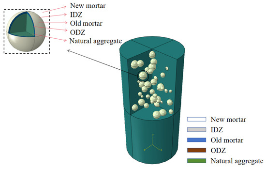
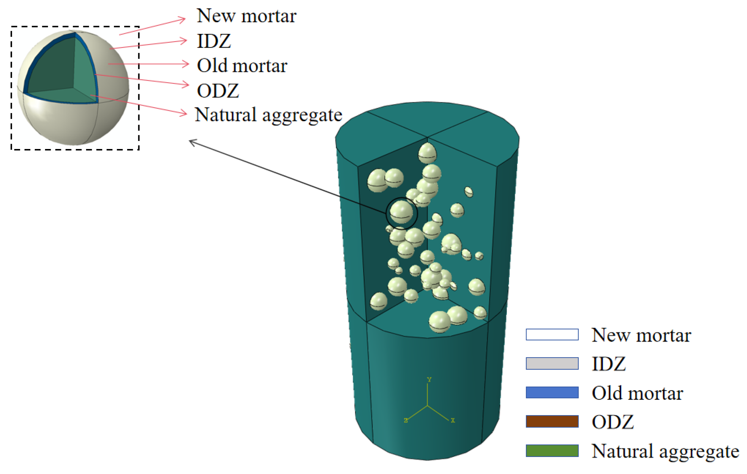
From the meso-scale perspective, RAC was regarded as a heterogeneous five-phase composite material composed of natural aggregates, an old, hardened mortar, the old interfacial transition zone (ODZ), new hardened mortar, and the new interfacial transition zone (IDZ). If a homogeneous macroscopic model is adopted, it is hard to capture stress concentration within weak interfacial regions, crack initiation positions and rising probability of defect accumulation as specimen size increases. The three-dimensional mesoscopic model can directly consider random aggregate distribution and material parameter differences in various phases at the member scale and is thus more applicable to exploration of failure evolution and size effect of CFRP-confined RAC short columns. This treatment can more realistically reflect the internal material composition and mesoscopic defect distribution characteristics of recycled concrete, thereby providing a more reasonable description of its compressive failure process. The interfacial transition zone (ITZ) was simulated with degraded material parameters to characterize the mechanical degradation of interfacial regions in RAC. A two-stage gradation was adopted for the RAC aggregates, with particle sizes ranging from 20 to 40 mm. The quantity of aggregates was determined according to the Fuller gradation curve [25], as given in Equation (1). Based on the Monte Carlo method [26], recycled aggregates were generated as spatially randomly distributed spheres using Python (Version 2.7) to construct a three-dimensional meso-scale RAC model. Subsequently, external CFRP confinement was superimposed on the conventional concrete model to establish a three-dimensional finite element analysis model of the CFRP-confined RAC short column; the CFRP material adopted a linear elastic orthotropic model; and its failure behavior was characterized by the Hashin damage criterion. In terms of boundary conditions, displacement-controlled axial loading was imposed on the top surface, and full constraint was applied at the bottom. Meanwhile, the contact relation and constraint mode between CFRP and concrete were defined, as shown in Figure 1:
where P is the mass proportion of aggregates passing through the sieve opening diameter D0, D0 is the sieve diameter, and Dmax is the maximum particle size.
Figure 1.
Three-dimensional geometric model.
2.2. Material Constitutive Relationships
The constitutive model for RAC was established based on the concrete damaged plasticity (CDP) model in ABAQUS, with reference to the five-phase constitutive curves proposed by Yue Qiang [27]. The material property parameters adopted for the five-phase material system are listed in Table 1.
Table 1.
Material property parameters of the five-phase material system.
CFRP was modeled using a composite layup approach, with a standard thickness of 0.167 mm assigned to each layer, so as to ensure that the model could capture the laminated characteristics and mechanical behavior of the FRP confinement material.
2.3. Validation of the Meso-Scale Model
A comparative analysis was carried out with reference to the test specimens reported in Ref. [28]. G25S0C2D28-1 and G50S0C2D28-1 were both CFRP-confined RAC cylindrical specimens, yet they differed in recycled aggregate replacement ratio, with the former at 25% and the latter at 50%. The relevant parameters were selected as follows: the dimensions of the CFRP-confined recycled aggregate concrete columns were 150 mm × 300 mm; the designed concrete strengths were 42.48 MPa and 40.41 MPa, respectively; the recycled aggregate replacement ratios were 25% and 50%, respectively; the elastic modulus of concrete, was 31.81 GPa and 32.52 GPa, respectively; and the elastic modulus of CFRP, , was 232 GPa.
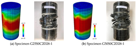
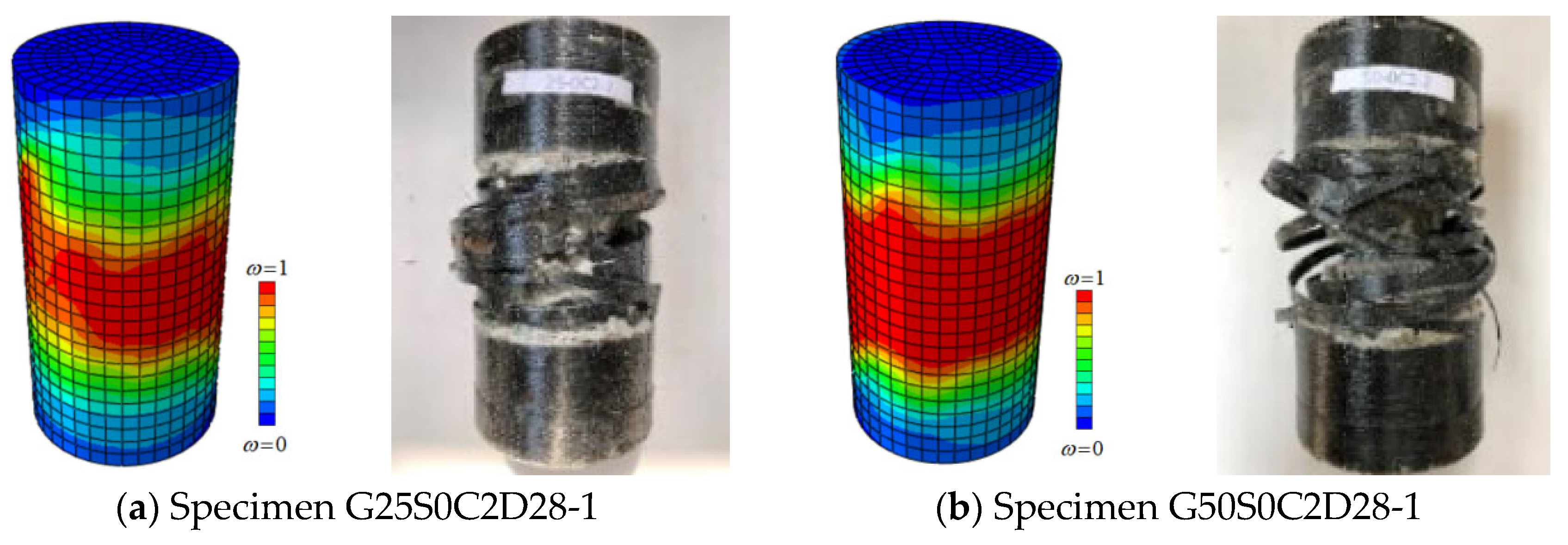
A comparison of the failure modes between the experimental and simulated results is presented in Figure 2. The comparison shows that the numerical simulation agrees well with the experimental observations in terms of failure location, damage distribution, and final failure pattern. In both cases, compressive damage developed in the middle region of the column and eventually led to crushing failure, indicating that the established model can effectively reproduce the compressive damage evolution process of FRP-confined RAC columns.
Figure 2.
Comparison of failure modes between the experiment and simulation.
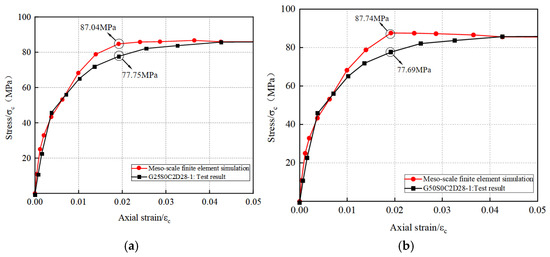
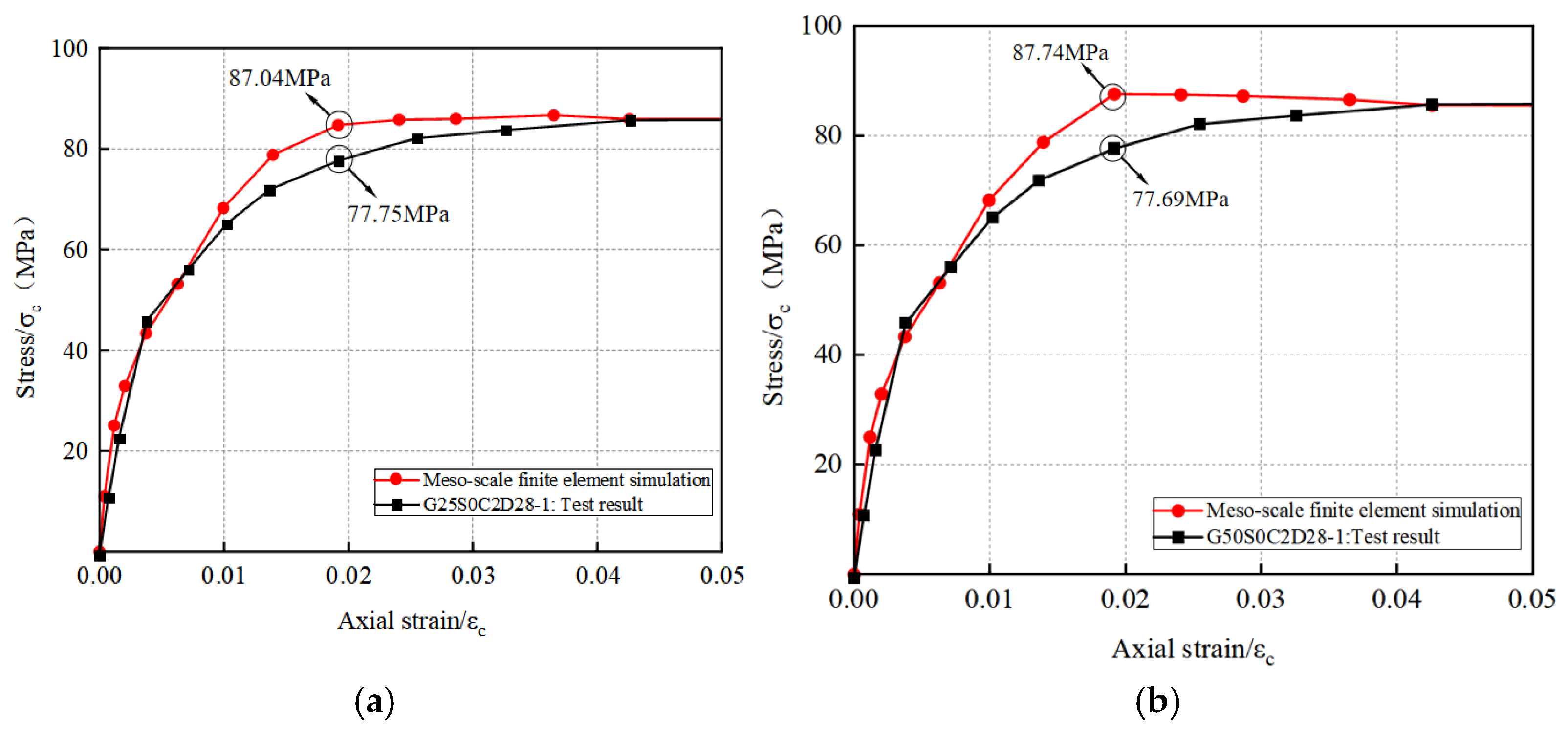
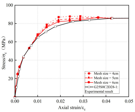
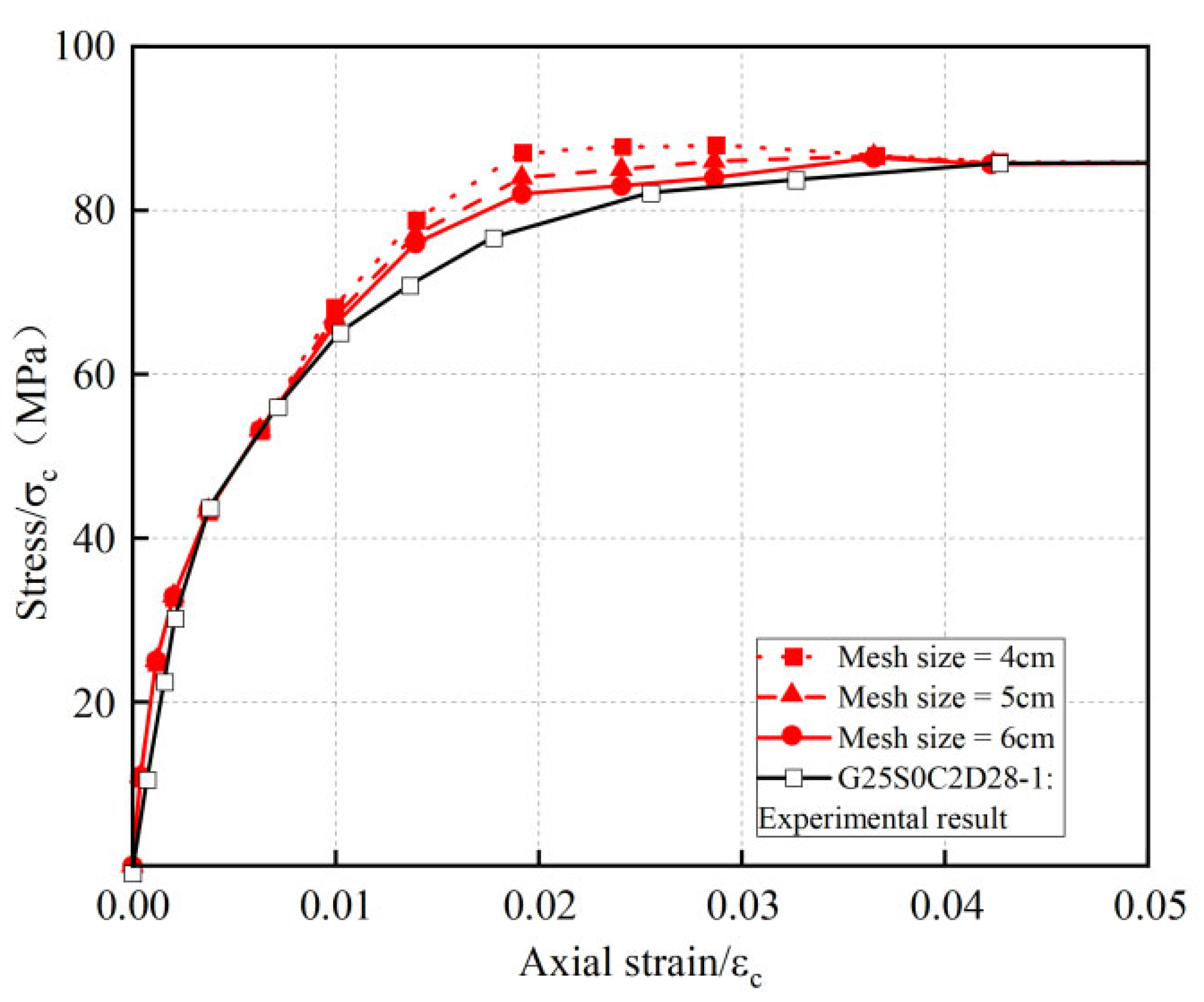
The comparison of the stress–strain curves is shown in Figure 3. The errors between the simulated peak stresses and the experimental results for the two groups of specimens were 10.7% and 11.7%, respectively, showing generally good agreement. Furthermore, a mesh sensitivity analysis was performed using three mesh sizes of 4 cm, 5 cm, and 6 cm, as shown in Figure 4. Mesh sizes of 4 cm, 5 cm and 6 cm correspond to relatively fine, medium and coarse mesoscopic grids, respectively, and were adopted to assess the trade-off between calculation accuracy and computational cost. The results indicate that the curves obtained with different mesh sizes are all close to the experimental values, with errors ranging from 7.01% to 11.86%. Considering both computational efficiency and accuracy, a mesh size of 5 cm was adopted uniformly in the subsequent analysis. It should be noted that current model validation relies only on limited existing experimental data, which mainly proves the model can reasonably reproduce experimental failure modes and stress–strain curve trends. Its broader applicability still needs further verification via tests covering diverse specimen sizes, replacement ratios, CFRP confinement layers and material sources.
Figure 3.
Comparison of stress–strain curves between the experiment and simulation. (a) Comparison between experimental and simulated results for G25S0C2D28-1. (b) Comparison between experimental and simulated results for G50S0C2D28-1.
Figure 4.
Mesh sensitivity analysis.
3. Results and Analysis of the Three-Dimensional Meso-Scale Finite Element Simulations
Based on the three-dimensional meso-scale simulation method validated in the previous section, CFRP-confined RAC short-column models with different sizes were designed to investigate the effects of replacement ratio and number of confinement layers on the compressive performance and size effect of RAC short columns under static loading. The variable parameters included four cross-sectional sizes (R = 75 mm, 150 mm, 300 mm, and 600 mm), four replacement ratios (r = 0%, 25%, 50%, and 75%), and three numbers of CFRP layers (n = 1, 2, and 3), resulting in a total of 48 specimens. The main design parameters of the specimens are listed in Table 2. It should be noted that X denotes different replacement ratios, and Y denotes different numbers of confinement layers.
Table 2.
Geometric Parameters of the Numerical Models under Static Loading.
3.1. Failure Mode Analysis
3.1.1. Failure Modes Under Different Replacement Ratios
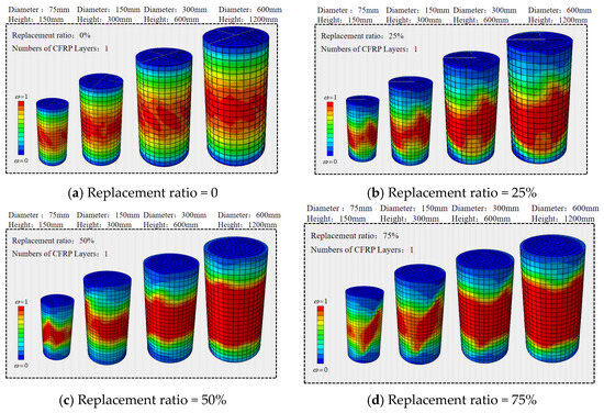
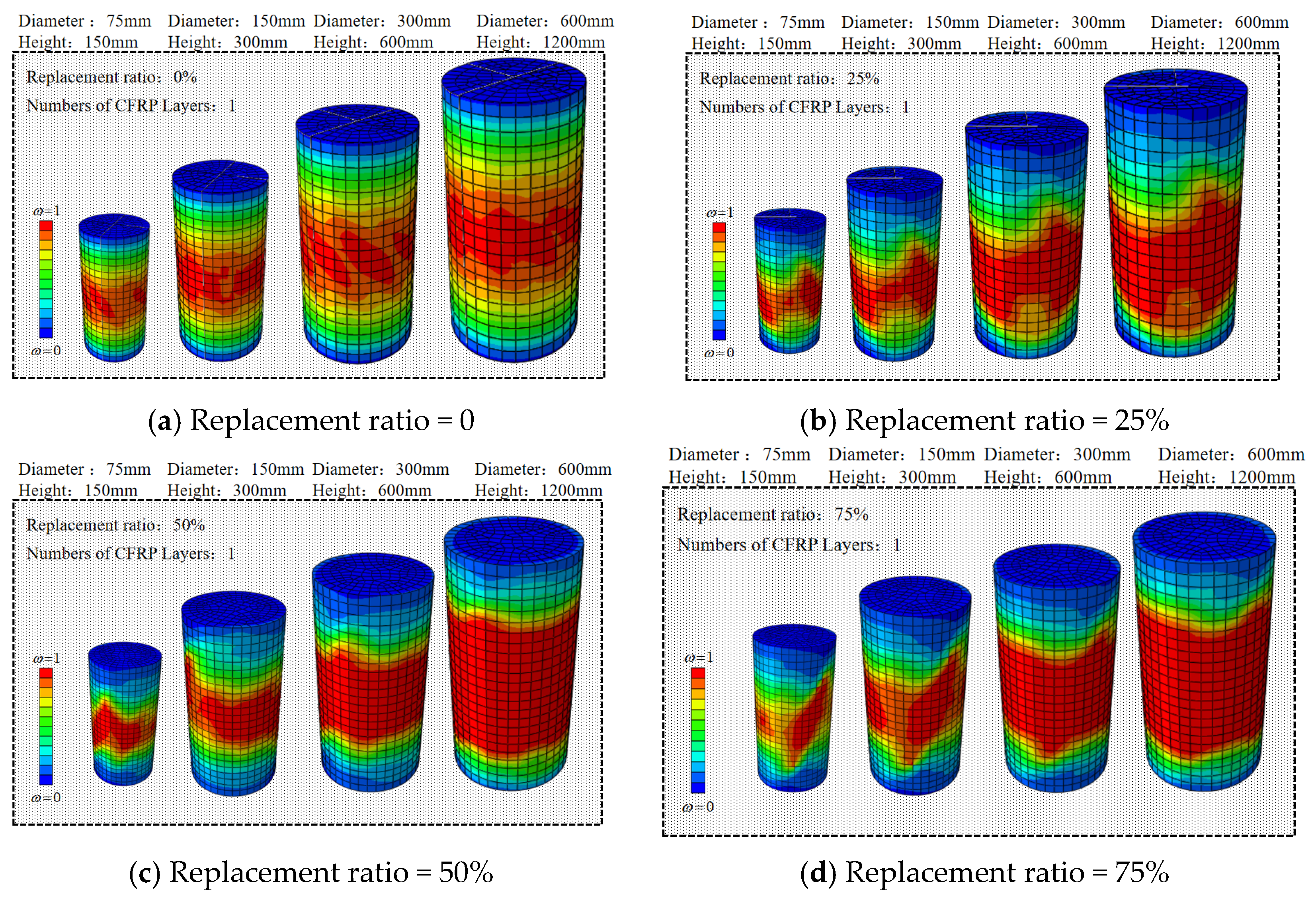
The failure modes of CFRP-confined RAC short columns with different replacement ratios and different sizes are shown in Figure 5. Under the same confinement condition and specimen size, all FRP-confined RAC short columns exhibited typical damage characteristics under axial compression. The highly damaged region was mainly concentrated in the middle-lower part of the column and gradually extended along the circumferential direction, with overall failure dominated by the accumulation of compressive damage and local crushing. As the replacement ratio increases, continuous damage zones are more likely to form in weak interfacial regions. When the specimen size increases, the number of potential internal weak zones is expanded, and the probability of generating critical defect combinations and localization-driven failure paths also increases. Consequently, large-sized specimens tend to experience concentrated damage under low-average stress levels. This indicates that the size effect is not solely induced by geometric dimensions but arises from the joint action of spatial accumulation of internal heterogeneous defects in RAC and lateral confinement of CFRP.
Figure 5.
Failure modes of CFRP-confined RAC short columns under different replacement ratios and specimen sizes.
3.1.2. Failure Modes Under Different Numbers of CFRP Layers
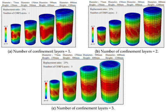
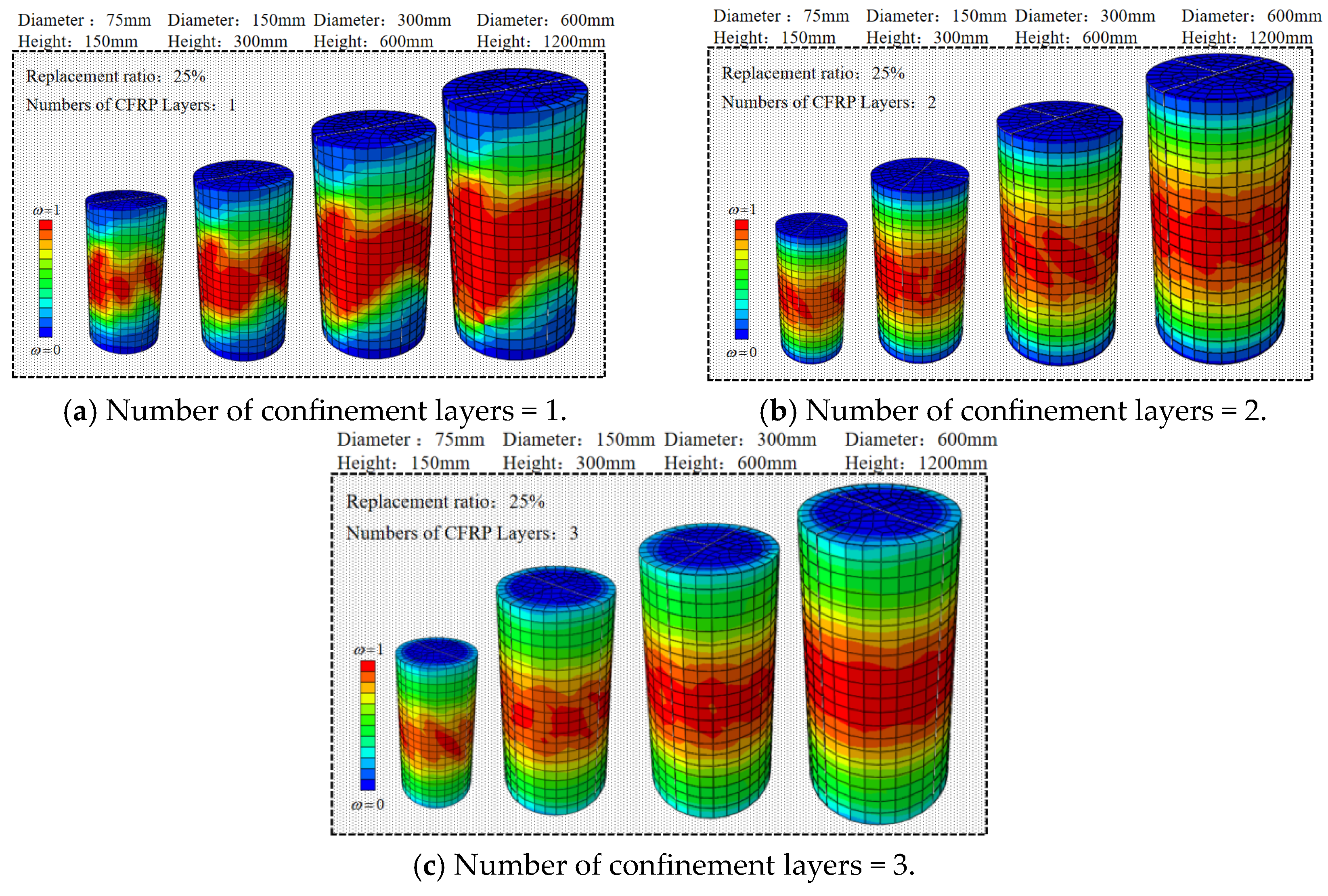
The failure modes of CFRP-confined RAC short columns with different numbers of CFRP layers and different sizes are shown in Figure 6. Under the same specimen size and replacement ratio, as the number of CFRP confinement layers increased from one to three, the extent of the highly damaged region gradually decreased, the damage distribution became more uniform, and both local crushing and lateral expansion were markedly suppressed. This indicates that increasing CFRP layers can enhance hoop confinement stiffness, restrain concrete lateral expansion and internal crack propagation, and disperse concentrated damage areas. Nevertheless, larger specimens contain more internal defects and present a higher possibility of connectivity with weak zones. Although CFRP confinement boosts bearing capacity and ductility, it cannot fully eliminate the size effect. Hence, the CFRP layer number serves as a critical parameter to mitigate instead of eliminate the size effect.
Figure 6.
Failure modes of CFRP-confined RAC short columns under different numbers of CFRP layers and specimen sizes.
3.2. Stress–Strain Curve Analysis
3.2.1. Stress–Strain Curves Under Different Replacement Ratios
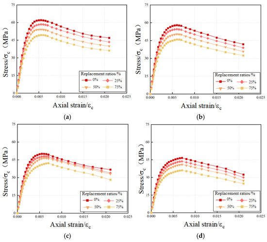
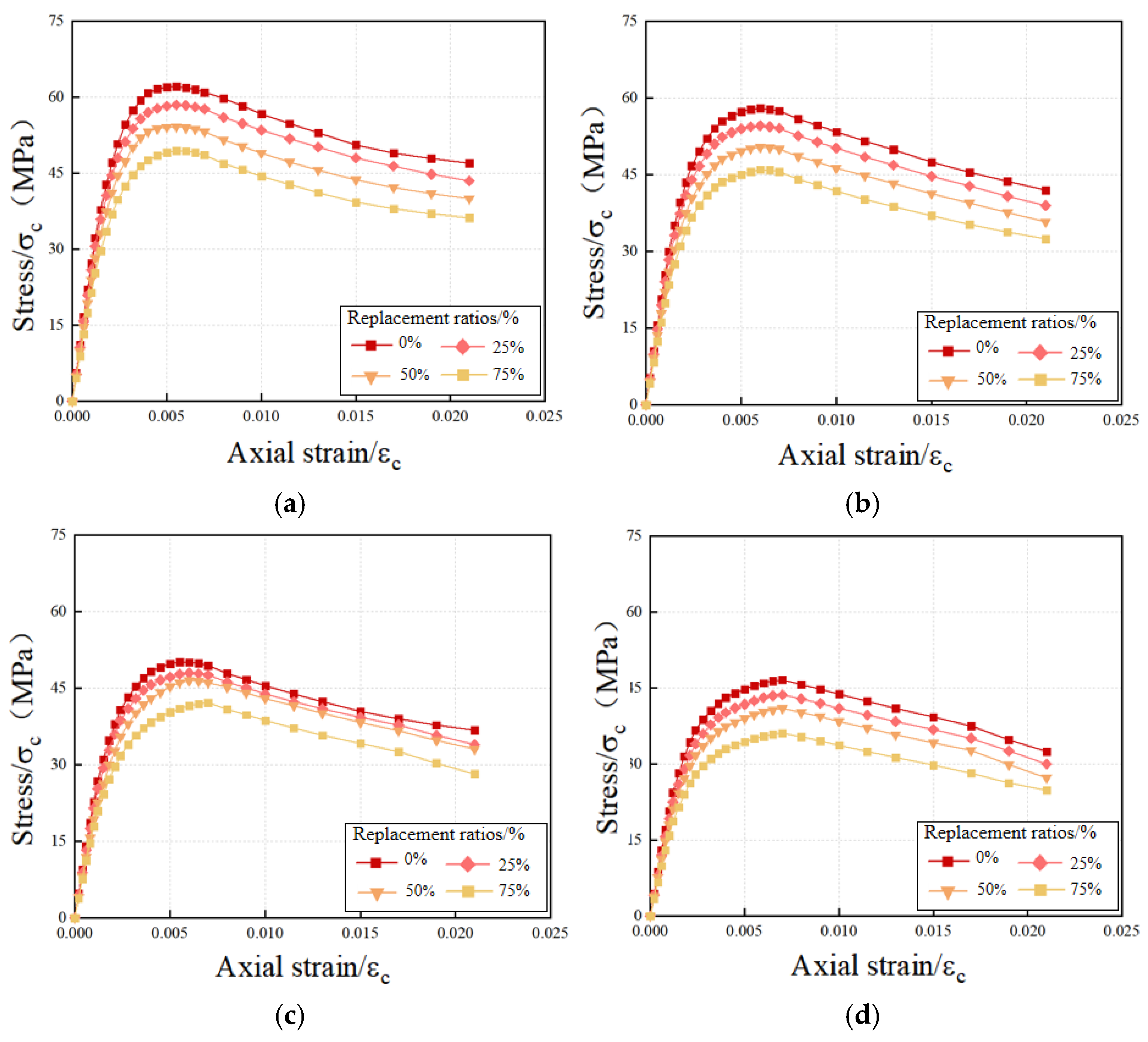
The stress–strain curves of the specimens under different replacement ratios are shown in Figure 7. As can be seen, all curves generally exhibit the basic characteristics of “rapid ascending stage—peak point—gradual post-peak descending stage.” In the initial stage, the curves rise rapidly, indicating that the specimens possess relatively high initial stiffness. After reaching the peak, due to the CFRP confinement effect, the post-peak load-carrying capacity does not drop abruptly but instead enters a stage of gradual degradation to a certain extent.
Figure 7.
Stress–strain curves under different replacement ratios and specimen sizes. (a) Stress–strain curves for specimens with a diameter of 75 mm. (b) Stress–strain curves for specimens with a diameter of 150 mm. (c) Stress–strain curves for specimens with a diameter of 300 mm. (d) Stress–strain curves for specimens with a diameter of 600 mm.
Taking the specimen with a diameter of 150 mm as an example, when the recycled aggregate replacement ratios were 0%, 25%, 50%, and 75%, the corresponding ultimate stresses were 58.0, 54.6, 50.4, and 46.0 MPa, respectively. Compared to the specimen with a 0% replacement ratio, the load-carrying capacity decreased by approximately 5.86%, 13.10%, and 20.69%, respectively. This indicates that the replacement ratio exerts a remarkable weakening effect on peak strength. Such an effect is more prominent in large-sized specimens, which demonstrates that increased specimen size magnifies the adverse impact of defects within old mortar and old interfacial transition zones on overall compressive performance. Accordingly, replacement ratio and specimen size are not independent influencing factors, and they jointly determine peak bearing capacity via defect counts, defect distributions and damage connectivity paths.
3.2.2. Stress–Strain Curves Under Different Numbers of CFRP Confinement Layers
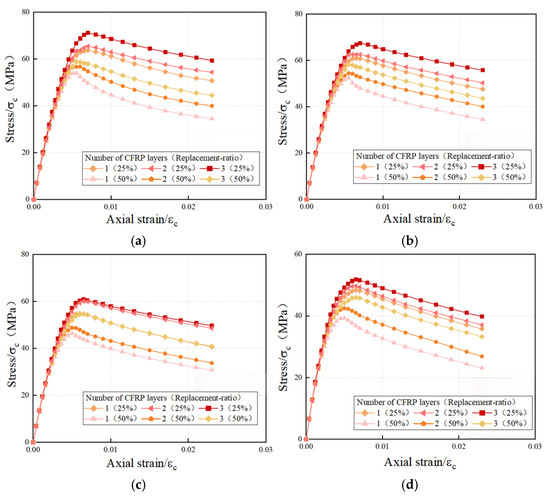
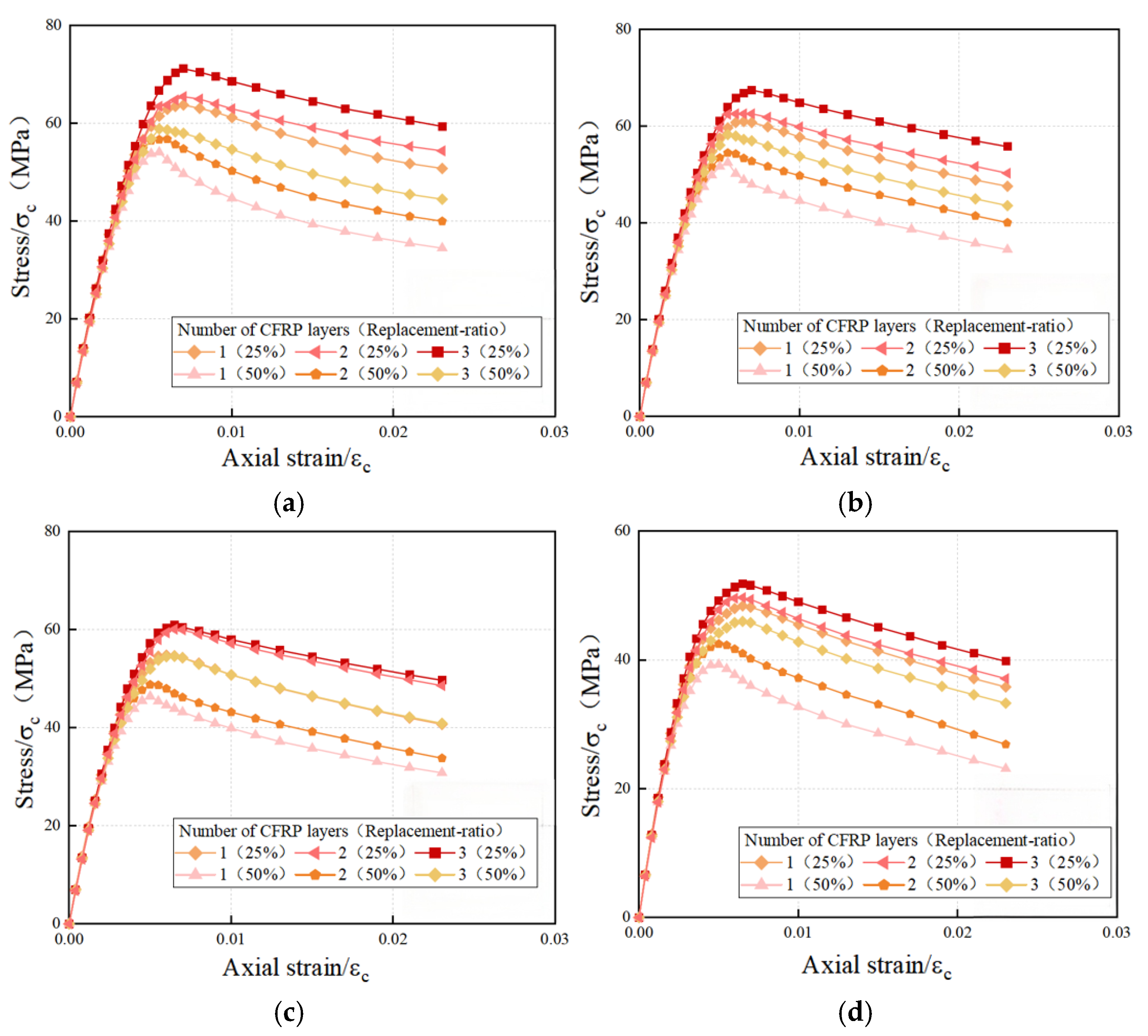
The stress–strain curves under different numbers of confinement layers are shown in Figure 8. It can be seen that, under the same specimen size and the same replacement ratio, the peak stress, peak strain, and post-peak load-carrying capacity retention of the specimens all increase significantly with the increase in the number of CFRP confinement layers. Taking specimens with a 25% replacement ratio as an example, when the diameter rises from 75 mm to 600 mm, the ultimate stress under one-, two- and three-layer CFRP confinement drops by about 25.2%, 24.1% and 27.6%, respectively. In contrast, as CFRP layers increase from one to three, the ultimate stress of specimens measuring 75, 150, 300 and 600 mm in diameter increases by approximately 25.9%, 23.9%, 25.0% and 21.9%, respectively. This reveals that more CFRP layers can markedly enhance bearing capacity, yet strength degradation induced by enlarged specimen sizes remains apparent, proving the existence of a coupling interaction between confinement effect and size effect.
Figure 8.
Stress–strain curves under different numbers of confinement layers and specimen sizes. (a) Stress–strain curves for specimens with a diameter of 75 mm. (b) Stress–strain curves for specimens with a diameter of 150 mm. (c) Stress–strain curves for specimens with a diameter of 300 mm. (d) Stress–strain curves for specimens with a diameter of 600 mm.
4. Development of a Simplified Stress–Strain Model for CFRP-Confined Recycled Concrete Short Columns
4.1. Modeling Strategy
To establish an axial compressive constitutive relationship for FRP-confined RAC short columns that can reflect the combined effects of the recycled aggregate replacement ratio, the number of CFRP confinement layers, and the specimen size, a modeling strategy based on a “peak-parameter model + normalized curve model” was adopted in this study. Specifically, prediction models for the peak stress and peak strain were first established, and then the ascending and descending branches were fitted separately based on the normalized stress–strain curves, thereby forming a simplified full-range expression. This method not only preserves the physical significance of the influencing parameters but also facilitates the development of a constitutive model with a concise form and strong applicability.
To ensure that the model remains concise in form and exhibits satisfactory parameter regressibility, the following assumptions were made in this study:
- (1)
- The axial compressive stress–strain curve can be described in segments by an ascending branch and a descending branch;
- (2)
- The peak stress, , and peak strain, , can be expressed as functions of the replacement ratio of the recycled coarse aggregate, r, the number of CFRP confinement layers, n, and the sectional diameter, D;
- (3)
- After normalization, the stress–strain curves under different working conditions exhibit good similarity and can therefore be described by a unified functional form;
- (4)
- Since all specimens investigated in this study have the same height-to-diameter ratio, the size effect is mainly characterized by the sectional diameter, D.
4.2. Normalization and Definition of Characteristic Parameters
The axial compressive stress–strain relationship of the CFRP-confined recycled concrete short column is assumed to be the following:
where σ is the axial stress and ε is the axial strain.
In this study, the peak stress , peak strain , and initial elastic modulus were selected as the key parameters characterizing the stress–strain curve. Here, was taken as the equivalent secant modulus corresponding to the stress at a strain of 0.0012, so as to provide a stable characterization of the stiffness of the material in the initial compression stage.
On this basis, the stress–strain curves under different parameter conditions were normalized.
The normalized strain and normalized stress are respectively defined as follows:
Accordingly, the original stress–strain relationship can be written as follows:
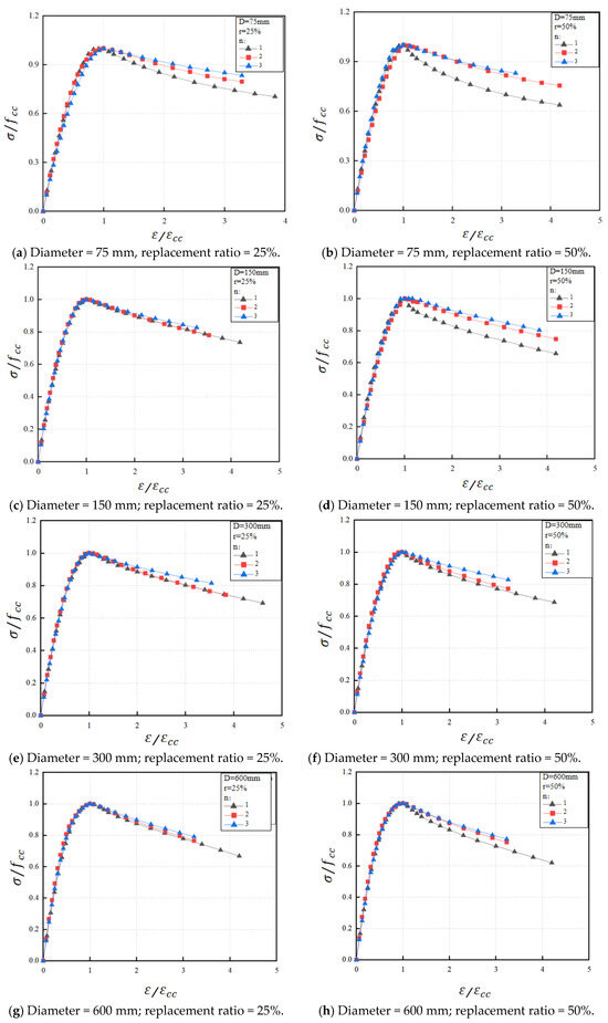
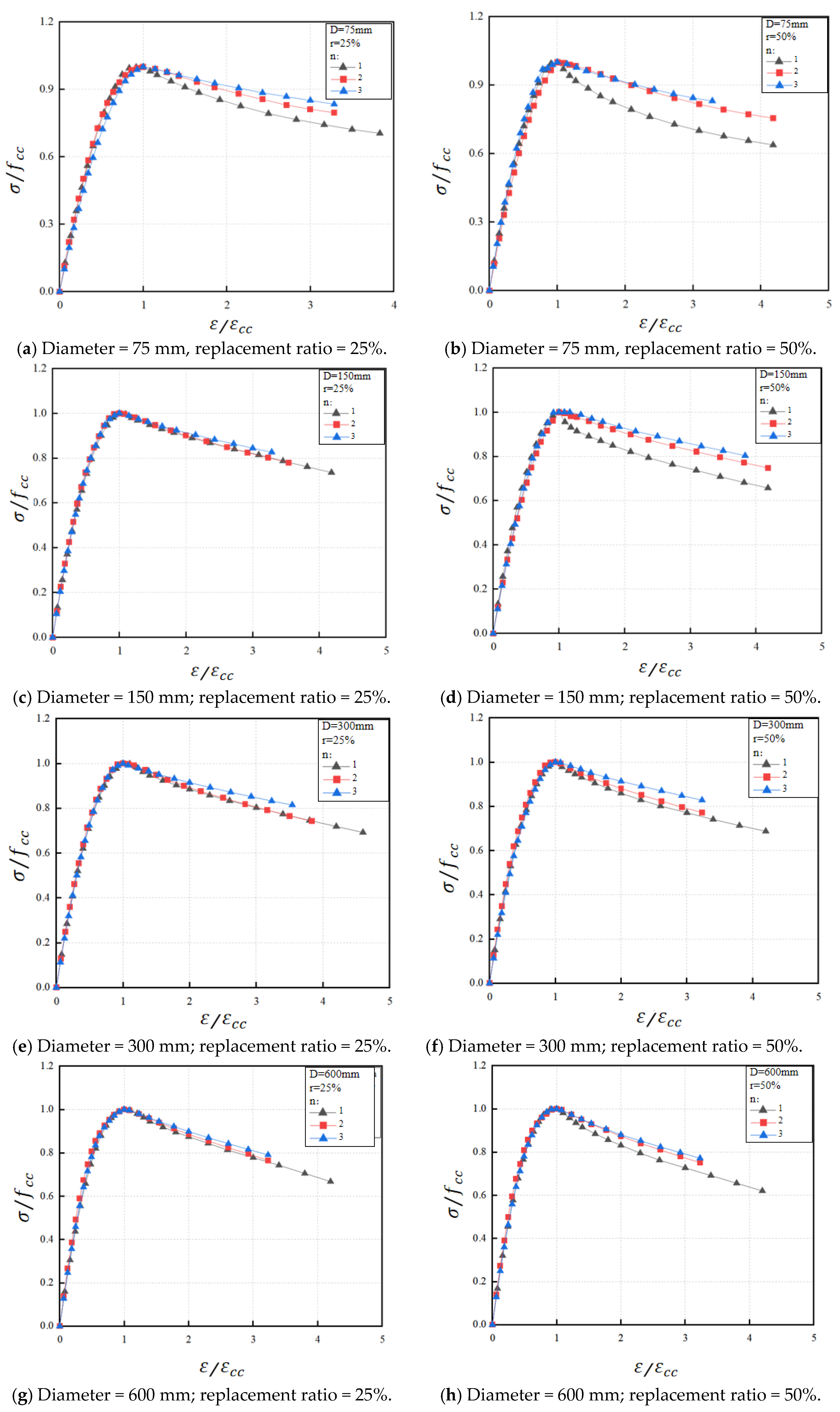
As shown in Figure 9, the normalized ascending branches of all specimens exhibit good similarity, whereas the differences in the post-peak descending branches are relatively evident. This indicates that the specimen size, replacement ratio, and number of confinement layers not only affect the peak characteristics, but also significantly influence the post-peak load-carrying capacity retention and softening rate. Therefore, it is reasonable to establish unified expressions separately for the ascending and descending branches. After normalization, the peak point of each curve is located at .
Figure 9.
Normalized curves under different parameters.
4.3. Prediction Models for Peak Stress and Peak Strain
4.3.1. Prediction Model for Peak Stress
To describe the peak load-carrying capacity of CFRP-confined recycled concrete short columns under different parameter conditions, a peak stress model was established using a multiplicative modification approach:
where is the peak stress of the reference specimen, is the replacement-ratio modification factor, and is the CFRP-layer modification factor.
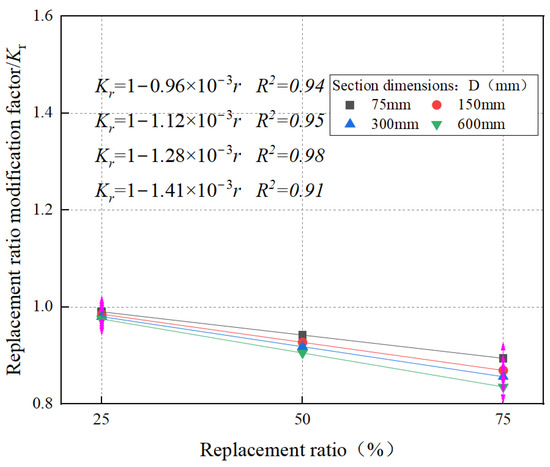
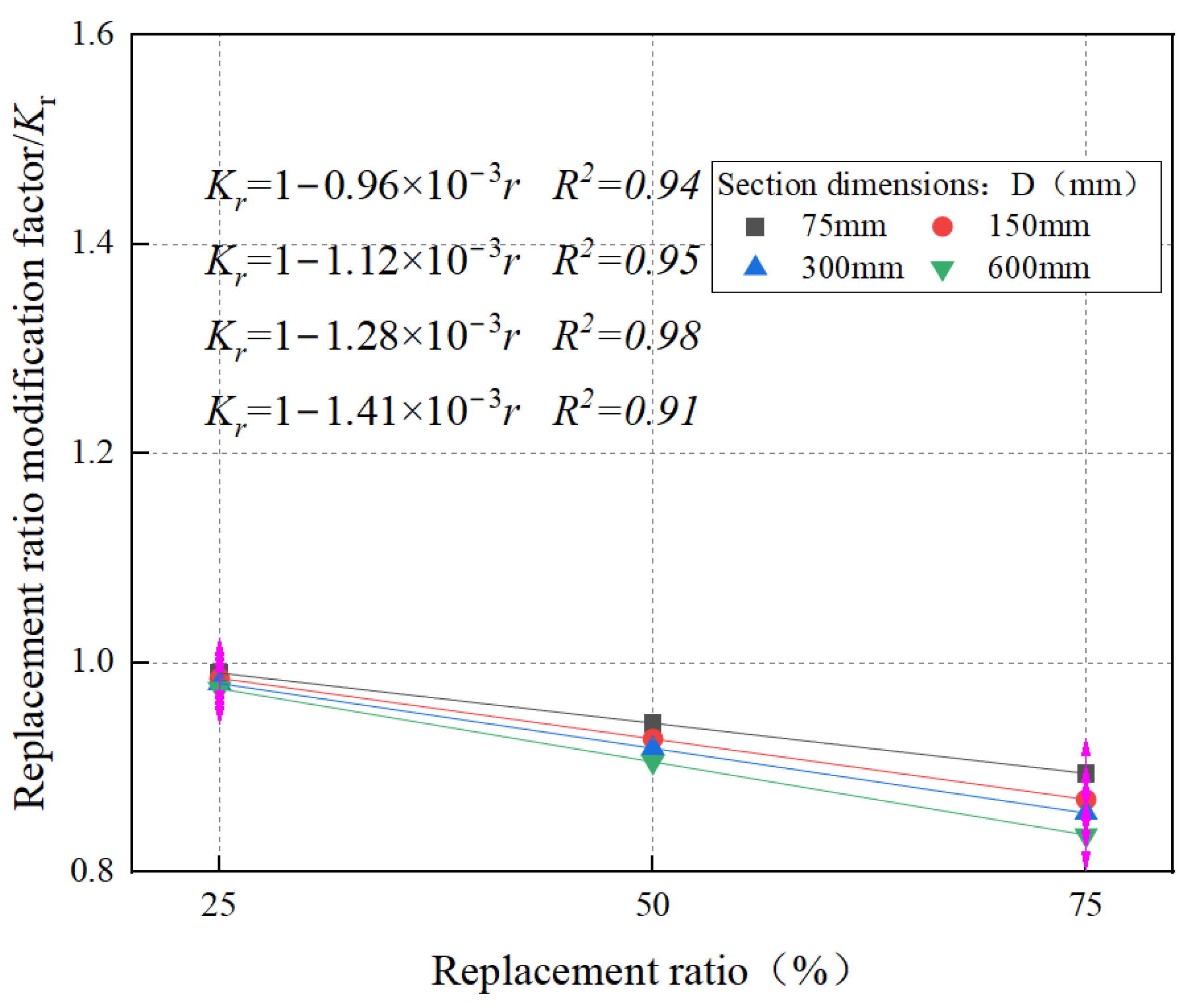
Considering that the results of this study show that peak stress generally exhibits a relatively stable monotonic decreasing trend with the increase in the replacement ratio of recycled coarse aggregate, the replacement-ratio modification factor can be expressed as follows:
where a1 is a regression coefficient, and r is the replacement ratio of recycled coarse aggregate. Figure 10 presents the variation trend of the replacement-ratio modification factor with r, together with the expressions of for different sectional sizes. Finally, a unified expression was obtained by fitting the relationship between coefficient a1 and D:
Figure 10.
Determination of the replacement-ratio modification factor
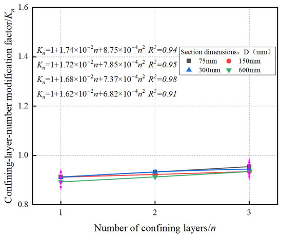
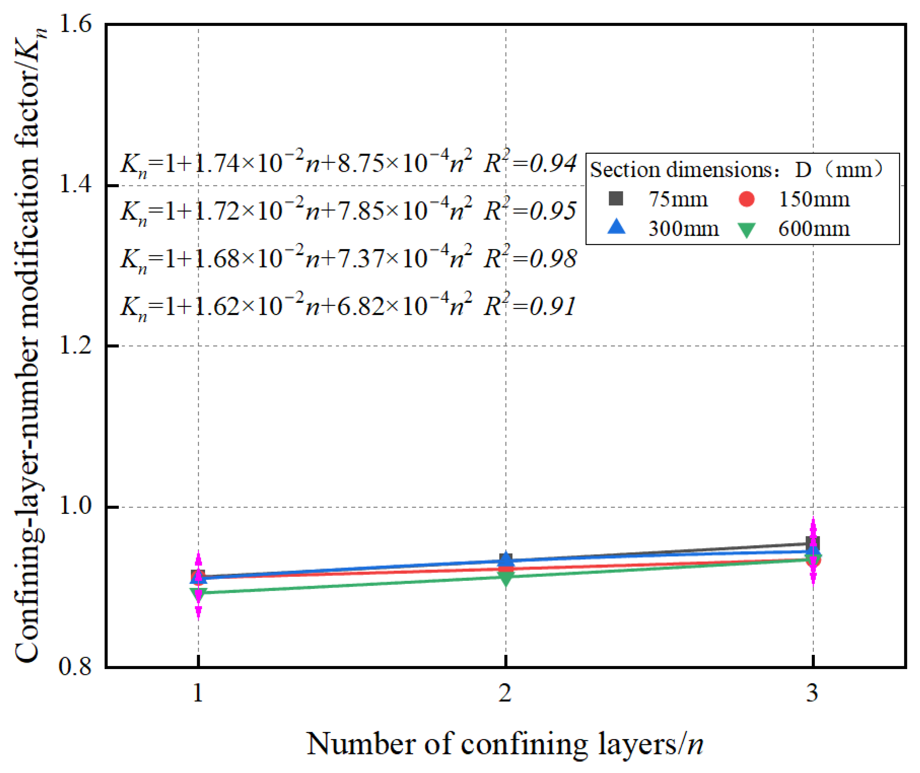
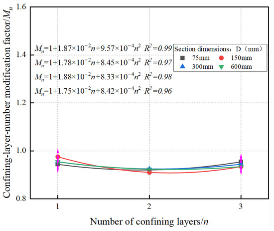
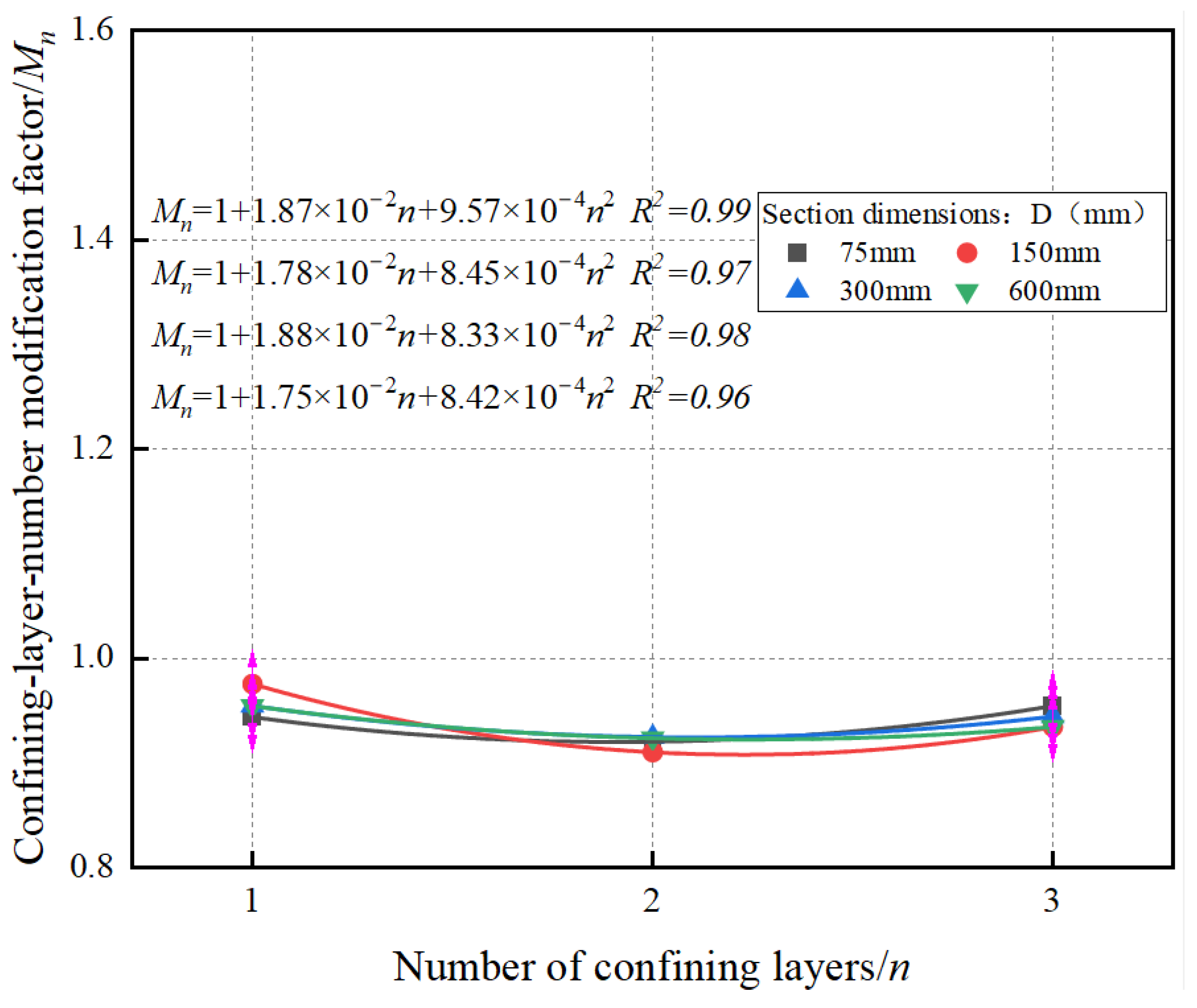
As the number of CFRP confinement layers increases, the peak stress exhibits a nonlinear increasing trend. Therefore, the modification term for the number of confinement layers was expressed using a quadratic polynomial:
where coefficients a2 and a3 were determined by regression fitting, and n is the number of CFRP confinement layers. Figure 11 presents the variation trend of the CFRP-layer modification factor with n, together with the expressions of for different sectional sizes. Finally, a unified expression was obtained by fitting the relationships of coefficients a2 and a3 with D:
Figure 11.
CFRP-layer modification factor
In summary, the peak stress model can be uniformly written as follows:
4.3.2. Peak Strain Model
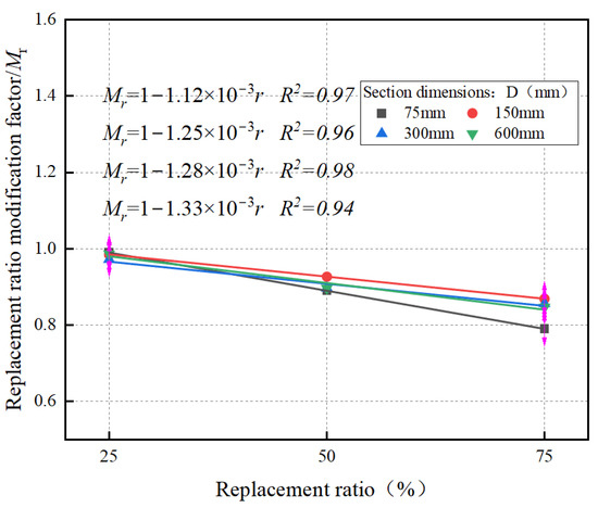
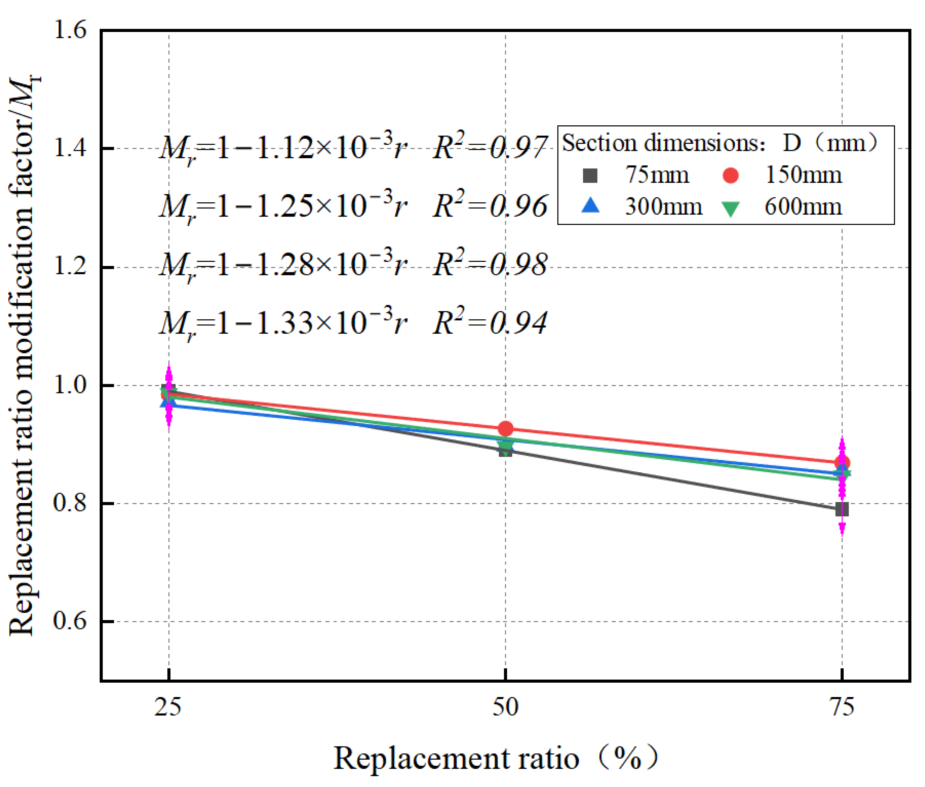
Peak strain is an important indicator characterizing the deformation capacity and ductility of the specimen. Considering that the replacement ratio of the recycled coarse aggregate, the number of CFRP confinement layers, and the specimen size also have significant effects on the peak strain, a peak strain model was established using a modified form similar to that of the peak stress model:
where is the peak strain of the reference specimen and is taken as 0.0022; Mr is the replacement-ratio modification factor; and Mn is the CFRP-layer modification factor.
Here, b1 is a regression coefficient, and r is the replacement ratio of recycled coarse aggregate. Figure 12 presents the variation trend of the replacement-ratio modification factor Mr with r, together with the expressions of for different sectional sizes. Finally, a unified expression was obtained by fitting the relationship between coefficient b1 and D:
Figure 12.
Determination of the replacement-ratio modification factor
The modification term for the number of confinement layers in the peak strain model was expressed using a quadratic polynomial:
where coefficients b2 and b3 were determined by regression fitting, and n is the number of CFRP confinement layers. Figure 13 presents the variation trend of the CFRP-layer modification factor with n, together with the expressions of for different sectional sizes. Finally, a unified expression was obtained by fitting the relationships of coefficients b2 and b3 with D:
Figure 13.
Determination of the replacement-ratio modification factor
The peak strain model is given by the following:
4.4. Simplified Expressions for the Ascending and Descending Branches of the Stress–Strain Curve
4.4.1. Ascending-Branch Model
For the normalized ascending branch, the function is required to satisfy the following conditions:
(a) It passes through the origin;
(b) It satisfies at the peak point;
(c) Its initial slope is consistent with the initial stiffness of the material.
Based on the above requirements, a Popovics-type function was adopted in this study to describe the ascending branch:
where α is the shape parameter of the ascending branch, and x and y are the normalized strain and normalized stress, respectively.
Accordingly, the initial slope of the normalized curve is as follows:
The initial slope of the Popovics function is as follows:
By setting the initial slope of the normalized curve equal to that of the Popovics function, the following is obtained:
Through algebraic rearrangement, the expression for α can be derived as follows:
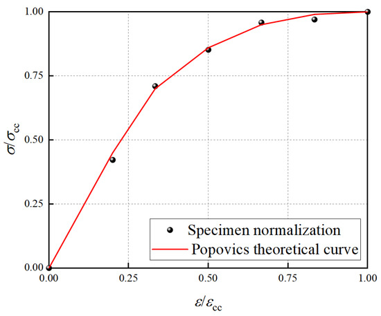
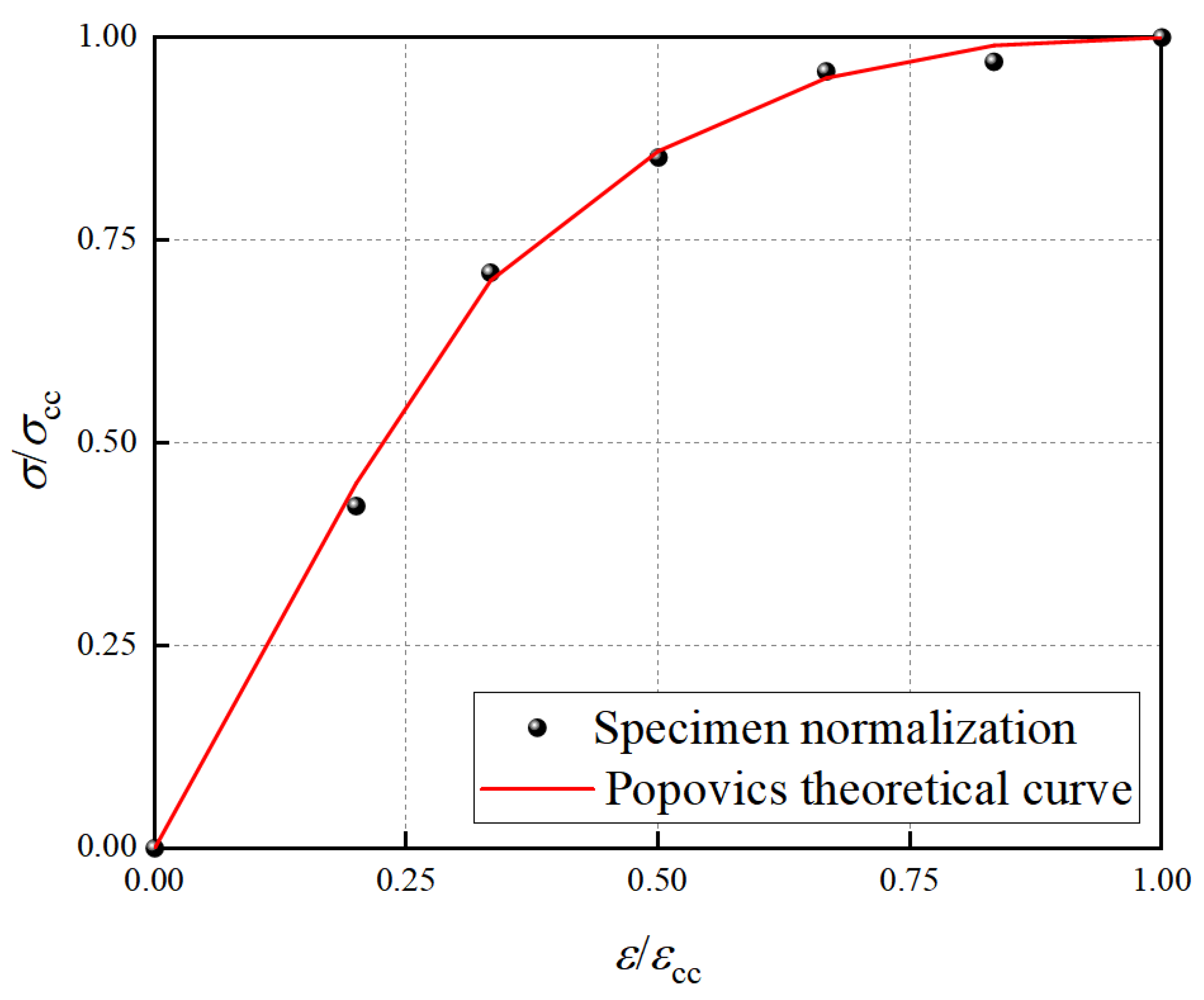
After normalization of the specimens, the fitting results are shown in Figure 14. As can be seen, the Popovics theoretical curve agrees closely with the simulation data, with . This indicates that the derived calculation method for the shape parameter α is accurate and reliable, and that the Popovics-type function can effectively describe the ascending-branch characteristics of the axial compressive stress–strain curves of CFRP-confined recycled concrete short columns.
Figure 14.
Comparison between the Popovics theoretical curve and simulation data.
4.4.2. Descending-Branch Model
To fully describe the post-peak softening behavior of CFRP-confined recycled concrete short columns under axial compression, a rational-function form was further adopted on the basis of the Popovics function for the ascending branch to construct the normalized descending-branch model. The descending branch takes the normalized strain and normalized stress as the basic variables, where x > 1 represents the post-peak region in which the strain exceeds the peak strain.
In this equation, β is the post-peak descending-rate parameter, which reflects the rate of stress degradation, while γ is the post-peak shape parameter, which characterizes the curvature of the post-peak curve and the distribution pattern of the degradation. Different values of β and γ lead to changes in both the steepness and curvature of the descending branch, thereby reflecting the differences in post-peak load-retention capacity under different confinement levels, replacement ratios, and specimen sizes.
In combination with the already determined ascending-branch parameter α and the variation pattern of peak levels for different specimens, two normalized post-peak control points were uniformly selected as x1 = 1.5 and x2 = 3.0, and the corresponding y1 and y2 values for each specimen were calculated.
For convenience of derivation, calculate the following:
where A1 and A2 denote the quantities obtained by algebraic transformation of the two post-peak control points. From Equations (24) and (25), one obtains the following:
Solving the above equations simultaneously gives γ and β:
As can be seen from Table 3, with the increase in the replacement ratio or specimen size, y1 and y2 generally show a decreasing trend, reflecting the weakening of the post-peak load-retention capacity. In contrast, when the number of confinement layers increases, the predicted control points increase accordingly, indicating that post-peak softening is alleviated under stronger confinement. Accordingly, the resulting β generally increases and γ increases slightly, suggesting that the post-peak descending rate accelerates as unfavorable factors become stronger, whereas the shape parameter is used to further refine the curvature of the descending branch.
Table 3.
Control points and parameters of the descending branch for selected specimens.
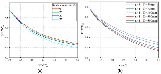
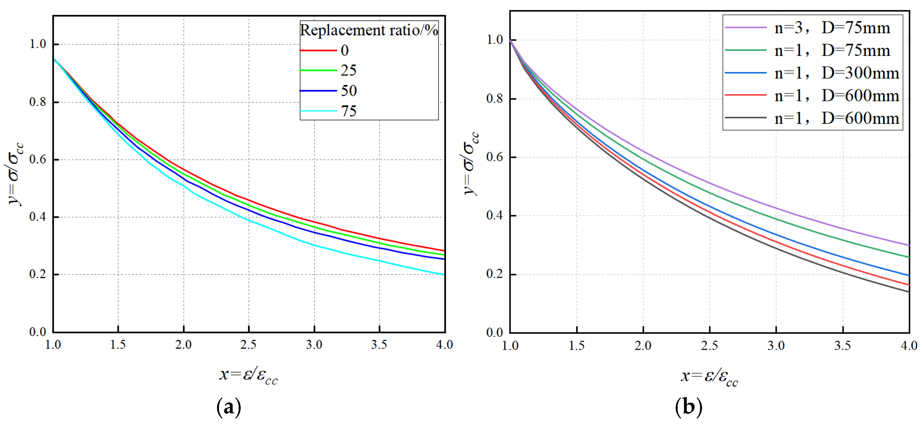
By comparing the Popovics theoretical fitting curves under different parameter combinations, as shown in Figure 15, it can be seen that this shape parameter can effectively adjust the curvature variation in the descending branch and accurately reflect the rapid degradation characteristics of the post-peak load-carrying capacity.
Figure 15.
Popovics theoretical fitting curves under different parameter combinations. (a) Theoretical descending-branch curves under different replacement ratios at n = 1 and D = 150. (b) Representative theoretical descending-branch curves under different specimen sizes and numbers of confinement layers at r = 25%.
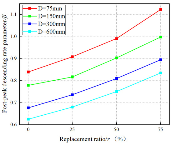
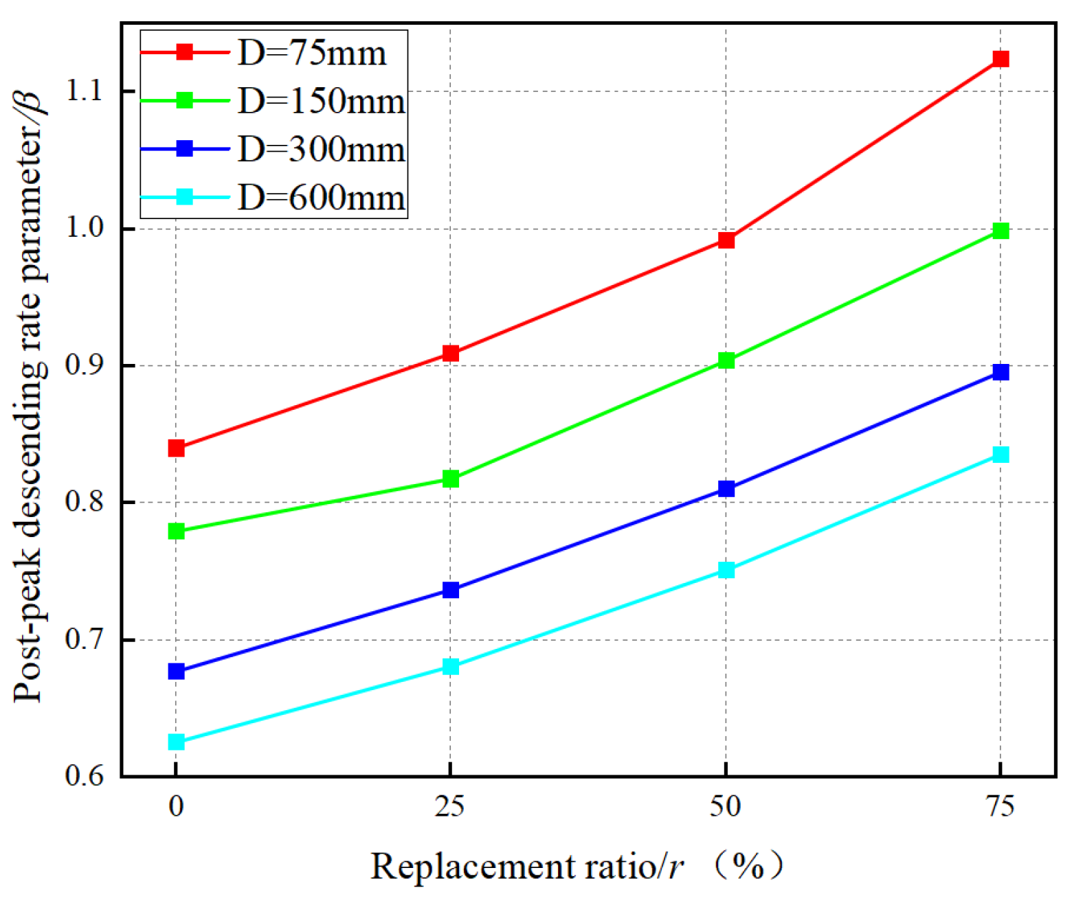
Taking the case of one confinement layer as an example, this study investigated the variation trend of β with replacement ratio and specimen size, as shown in Figure 16. It can be seen that β increases with the increase in the replacement ratio, indicating that a higher replacement ratio of recycled coarse aggregate significantly accelerates the post-peak stress degradation rate.
Figure 16.
Variation trend of β with replacement ratio and specimen size when n = 1.
After calculating β and γ for each specimen, they can be further expressed as functions of specimen size D, replacement ratio r, and number of confinement layers n. In this study, the following linear combination forms were adopted to regress β and γ:
Based on the current sample data, least-squares regression was performed to determine the coefficients in the expressions of the descending-branch parameters, as listed in Table 4. The coefficients of determination are = 0.9655 and = 0.9350, respectively, indicating that the proposed parameter expressions can effectively characterize the variation patterns of β and γ for the current sample set.
Table 4.
Regression coefficients and fitting coefficients of the descending-branch parameters.
In summary, the simplified full-range stress–strain model established in this study can be expressed as follows:
4.4.3. Comparison with Existing Models and Discussion
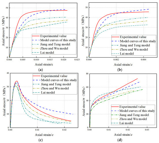
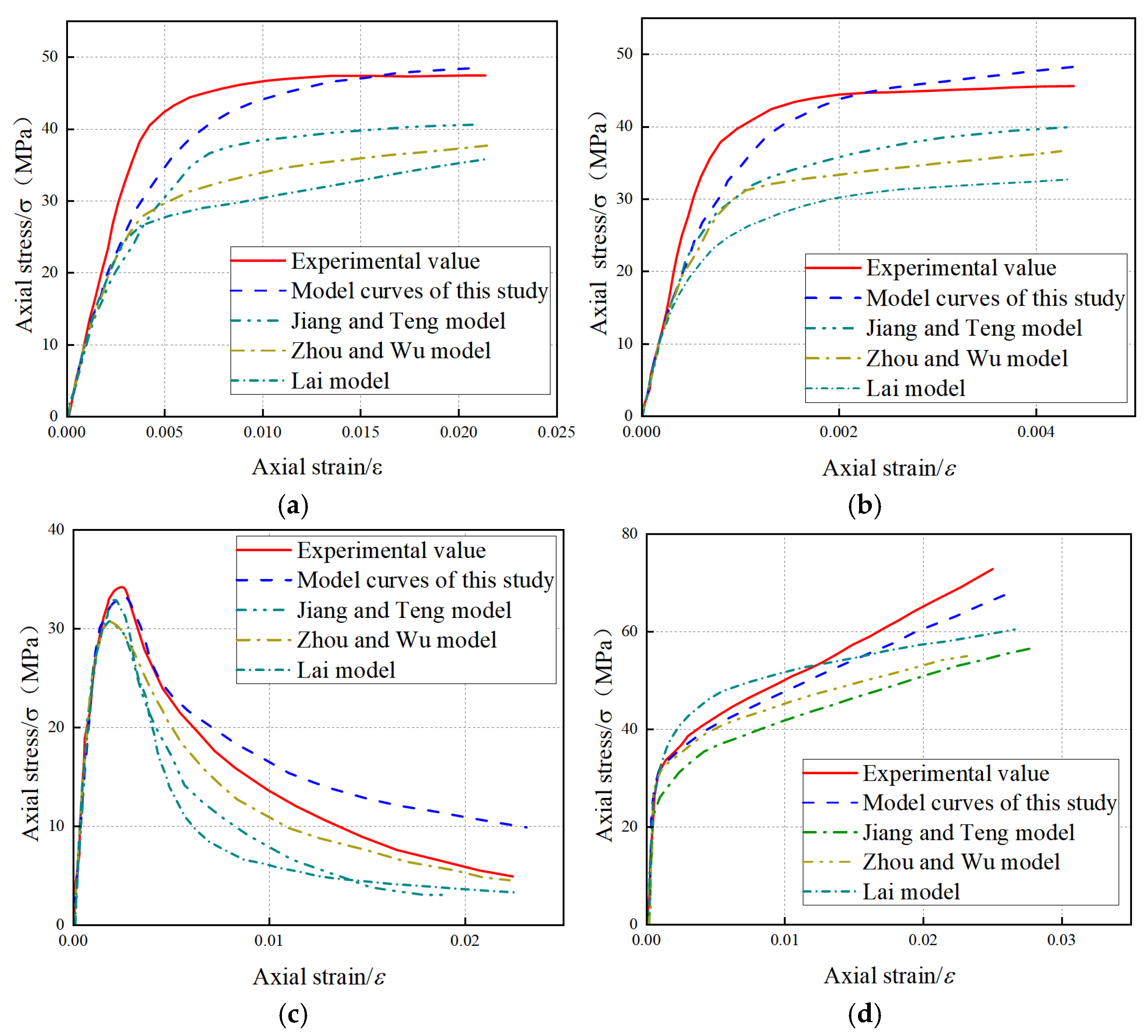
To verify the applicability of the established model, this paper selects three existing stress–strain models [29,30,31] for FRP-confined concrete columns (as shown in Table 5) and conducts a comparative analysis using existing experimental data. The existing models are primarily developed based on specimens of ordinary concrete or natural aggregate concrete, failing to fully account for the coupled effects of recycled aggregate replacement ratio, CFRP confinement layers, and component dimensions on the full-range response.
Table 5.
Existing prediction models for confined concrete.
The comparison results of the peak stress are shown in Table 6. The errors of the Jiang & Teng (2007) [29] model compared to the experimental data range from 7.4% to 22.2%, while the errors for the Zhou & Wu (2012) [30] model range from 8.8% to 19.4%, and the errors for the Lai (2020) [31] model range from 5.9% to 18.1%. In contrast, the errors for the model proposed in this study are only 1.5% to 6.9%, which are significantly lower than those of the above-mentioned models. This indicates that the model proposed in this study cannot only accurately predict the peak stress and peak strain but also better match the experimental results in terms of the ascending branch behavior and post-peak softening trend. The main reason for this difference is that the proposed model considers the influence of defects in the old mortar and old interfacial transition zones in recycled concrete on stress transfer and damage evolution at the meso-scale. Additionally, it systematically introduces three key parameters: replacement ratio, number of confinement layers, and size. Therefore, this model is more suitable for the full-range analysis of FRP-confined RAC short columns under compression. The comparison between the predicted and experimental stress–strain curves is shown in Figure 17.
Table 6.
Error analysis of peak stress.
Figure 17.
Comparison of model predictions and experimental values. (a) Comparison between experimental and predicted values for Ref. [19]. (b) Comparison between experimental and predicted values for Ref. [28]. (c) Comparison between experimental and predicted values for Ref. [20]. (d) Comparison between experimental and predicted values for Ref. [18].
5. Conclusions
The main research conclusions obtained through this research are as follows:
(1) The increase in the replacement ratio of recycled coarse aggregate (RCA) reduces the axial compressive load-carrying capacity of FRP-confined recycled aggregate concrete (RAC) short columns and accelerates the development and propagation of internal damage. As the replacement ratio rises, the ultimate stress of specimens exhibits an overall declining trend, indicating that defects in the old mortar and old interfacial transition zone (ITZ) within recycled aggregates weaken material continuity and further intensify stress concentration and damage localization under compression.
(2) Increasing the number of CFRP confinement layers significantly enhances the load-carrying capacity, deformation capacity, and post-peak load-carrying capacity retention of FRP-confined RAC short columns. With more confinement layers, lateral expansion and local crushing of specimens are effectively suppressed, resulting in a flatter post-peak descending branch of the stress–strain curve. This demonstrates that CFRP confinement markedly improves ductility and compressive stability.
(3) A pronounced size effect is observed in FRP-confined RAC short columns under axial compression. As specimen size increases, the ultimate stress decreases overall, suggesting that larger dimensions amplify the adverse effects of internal heterogeneity and initial defects, thereby weakening the overall compressive performance.
(4) This paper establishes a full-curve stress–strain model based on a mesoscopic finite element simulation, which simultaneously takes into account the recycled aggregate replacement ratio, CFRP layer quantity and member size. The goodness of fit for the ascending branch is . For the descending branch, the fitting coefficients are = 0.9655 and = 0.9350, with a model prediction error ranging from 1.5% to 6.9%, outperforming existing models. It should be noted that the proposed model is mainly derived from numerical simulation data, with limited experimental verification. Future research should further calibrate and extend the model through larger-sized tests, diverse height-to-diameter ratios, various CFRP materials and complex loading conditions.
Author Contributions
Conceptualization, C.L.; methodology, C.L. and F.A.; software, C.L. and Z.T.; validation, C.L.; formal analysis, C.L. and Z.Z.; investigation, W.H.; data curation, W.H. and Z.T.; writing—original draft preparation, C.L.; writing—review and editing, C.L., W.H., Z.Z. and F.A.; visualization, C.L. All authors have read and agreed to the published version of the manuscript.
Funding
This work was supported by the National Natural Science Foundation of China under Grant no. 52278507, the Natural Science Foundation of Shandong Province under Grant no. ZR2022ME160, Kashi University Research Startup Funding Project (Grant No. GCC2025ZK-021), and University-level research project (cultivation) (2025) 21022.
Data Availability Statement
Data will be made available on request.
Conflicts of Interest
The authors declare that they have no known competing financial interest or personal relationships that could have appeared to influence the work reported in this paper.
References
- Tan, R.W.; Shen, Z.W. Prediction of construction waste generation based on grey theory and SVM. Sichuan Archit. 2021, 41, 49–51. [Google Scholar]
- Hammad, H.; Elhakim, Y.; Mahmoud, M. Exploring the potential of incorporating plastic waste, textile sludge, and construction and demolition waste into concrete: A comparative study. Cogent Eng. 2024, 11, 2307217. [Google Scholar] [CrossRef] [Scilit]
- Xiao, J.Z.; Ma, X.W.; Liu, Q.; Zhang, H.H.; Duan, Z.H. Evolvement and research progress of concept for full recycled concrete. J. Archit. Civ. Eng. 2021, 38, 1–15. [Google Scholar] [CrossRef]
- Xiao, J.Z.; Huang, Y.J. Seismic performance and damage evaluation of GFRP tube-confined recycled concrete columns. China Civ. Eng. J. 2012, 45, 112–120. [Google Scholar] [CrossRef]
- Mouna, Y.; Suryanto, B. Recycled aggregate concrete: Effect of supplementary cementitious materials and potential for supporting sustainable construction. Materials 2025, 18, 5183. [Google Scholar] [CrossRef] [Scilit]
- Xiao, J.Z.; Li, J.B.; Sun, Z.P.; Hao, X.M. Study on the compressive strength of recycled concrete. J. Tongji Univ. (Nat. Sci.) 2004, 12, 1558–1561. [Google Scholar]
- Thomas, C.; Setien, J.; Polanco, J.A.; Alaejos, P.; de Juan, M.S. Durability of recycled aggregate concrete. Constr. Build. Mater. 2013, 40, 1054–1065. [Google Scholar] [CrossRef] [Scilit]
- Limbachiya, M.C.; Leelawat, T.; Dhir, R.K. Use of recycled concrete aggregate in high-strength concrete. Mater. Struct. 2000, 33, 574–580. [Google Scholar] [CrossRef] [Scilit]
- Wang, L.; Zhou, R.Q.; Liu, L.; Leng, C.Q.; Guo, W. Experimental study on the effects of recycled aggregate replacement ratio and particle size on the performance of manufactured-sand concrete. Concrete 2025, 3, 168–171. [Google Scholar]
- Tan, Y.S.; Peng, Y.K.; Wu, H. Uniaxial compressive constitutive relationship of recycled concrete with different recycled fine aggregate replacement ratios. Concrete 2019, 3, 65–70. [Google Scholar]
- Wang, G.L.; Qi, S.Y.; Li, J.Y.; Wang, K. Experimental study on the mechanical properties of recycled coarse aggregate concrete. Concrete 2020, 3, 168–171+176. [Google Scholar]
- Huo, H.Y.; Fan, C.C.; Chen, A.J.; Li, H.J.; Shao, C.; Huo, H.J. Effects of recycled aggregates with different strength grades on the basic mechanical properties of recycled concrete. Concrete 2017, 2, 60–62+65. [Google Scholar]
- Xu, Q.; Ye, L.M.; You, Y.C.; Ye, S.C. Study on the basic mechanical properties of recycled aggregate concrete. J. Harbin Univ. Commer. (Nat. Sci. Ed.) 2020, 36, 65–72+85. [Google Scholar] [CrossRef]
- Wang, S.L.; Yu, Y.; Zhang, B.; Zhao, K.; Fan, Y.J. Experimental study on the effects of fly ash and silica fume on the mechanical properties of recycled concrete. Concrete 2011, 12, 53–55. [Google Scholar] [CrossRef] [Scilit]
- Liang, J.F.; Jiang, L.Z.; Wu, H.Y.; Gu, L.S. Experimental study on axially compressed short recycled concrete columns confined with CFRP circular steel tubes. Concrete 2015, 3, 18–20. [Google Scholar]
- Ma, H.; Cui, H.; Li, Z.; Li, J.X. Axial compression behavior of recycled concrete columns confined with glass-fiber tubes. Chin. J. Appl. Mech. 2019, 36, 209–218, 264. [Google Scholar]
- Zeng, L.; Li, L.J.; Chen, G.M.; Xie, M.; Cui, J.J.; Han, W.G.; Pan, Z.F. Experimental study on the axial compressive behavior of GFRP-recycled concrete-steel tubular composite columns. China Civ. Eng. J. 2014, 47, 21–27. [Google Scholar] [CrossRef]
- Gu, G.M. Study on the Compressive Behavior of JFRP Tube-Confined Recycled Concrete Containing Sintered Brick Aggregates. Master’s Thesis, Hunan University, Changsha, China, 2017. [Google Scholar]
- Wang, H.T.; Chen, L.; Xu, G.W.; Xiong, H.; Mao, Y.H. Experimental study on the axial compressive behavior of BFRP tube-confined recycled aggregate concrete cylinders. J. Hohai Univ. (Nat. Sci.) 2023. Available online: https://oversea.cnki.net/kcms2/article/abstract?v=qQAO62XqY5JQhCidYU1Rr2Lw086EeIgiZeqG-6K7Oifhsc8HEBkylMF3O6Uc7fh70VWuGhsG7RAnoiTryMJwQqpyj4-Qpe-PurIAXycUxZtrQv5OYdbXrYhH-LgOD7pQUJGFWLI0luWANwV_7fXDkhyKiJL4R1SDmNWCB6fhl-mblJ3Tb-67IEfMnzUVZaYaOMrYVAGzbGk&uniplatform=OVERSEA&language=EN&captchaId=81de98a2-eed6-4d64-8ef2-ee2d9a138f71 (accessed on 15 December 2025).
- Xu, H.L. Finite element analysis of GFRP tube-confined seawater sea-sand recycled concrete short columns under axial compression. Guangdong Build. Mater. 2021, 37, 55–58, 29. [Google Scholar]
- Hua, W.; Dong, S.M.; Xu, J.G. Experimental study on the mechanical properties of FRP-strengthened recycled concrete cylinders. Appl. Math. Mech. 2014, 35, 299–303. [Google Scholar]
- Li, J.Q.; Li, S.X.; Hu, H.; Dong, J.F. Experimental study on the mechanical properties of FRP-confined basalt-fiber recycled concrete cylinders. Concrete 2018, 12, 57–61. [Google Scholar]
- Chen, G.M.; Zhang, J.J.; Jiang, T.; Lin, C.J.; He, Y.H. Compressive behavior of CFRP-confined recycled aggregate concrete in different-sized circular sections. J. Compos. Constr. 2018, 22, 04018021. [Google Scholar] [CrossRef] [Scilit]
- Liu, C.Y.; Qin, J.H.; Lin, Y.Y.; Gao, Y.Q.; Zhou, G.K. Mesoscopic simulation study on compressive failure of recycled concrete considering size effect. J. Shandong Jianzhu Univ. 2024, 39, 1–11. [Google Scholar]
- Zhang, Z.M. Analysis of Meso-Mechanical Model of Recycled Concrete Based on Random Aggregates. Master’s Thesis, Huazhong University of Science and Technology, Wuhan, China, 2020. [Google Scholar] [CrossRef]
- Lilliu, G.; van Mier, J.G.M. 3D lattice type fracture model for concrete. Eng. Fract. Mech. 2003, 70, 927–941. [Google Scholar] [CrossRef] [Scilit]
- Yue, Q.; Wang, L.; Liu, F.S.; An, X. Numerical study on the failure of recycled concrete based on a real mesoscopic model. J. Build. Mater. 2016, 19, 221–228. [Google Scholar]
- Zhang, X.W. Experimental Study on the Axial Compression Mechanical Properties of CFRP-Confined Recycled Glass Aggregate Concrete. Master’s Thesis, Guangdong University of Technology, Guangzhou, China, 2019. [Google Scholar] [CrossRef]
- Jiang, T.; Teng, J.G. Analysis-oriented stress-strain models for FRP-confined concrete. Eng. Struct. 2007, 29, 2968–2986. [Google Scholar] [CrossRef] [Scilit]
- Zhou, Y.W.; Wu, Y.F. General model for constitutive relationships of concrete and its composite structures. Compos. Struct. 2012, 94, 580–592. [Google Scholar] [CrossRef] [Scilit]
- Lai, M.H.; Liang, Y.W.; Wang, Q.; Ren, F.M.; Chen, M.T.; Ho, J.C.M. A stress-path dependent stress-strain model for FRP-confined concrete. Eng. Struct. 2020, 203, 109824. [Google Scholar] [CrossRef] [Scilit]

Disclaimer/Publisher’s Note: The statements, opinions and data contained in all publications are solely those of the individual author(s) and contributor(s) and not of MDPI and/or the editor(s). MDPI and/or the editor(s) disclaim responsibility for any injury to people or property resulting from any ideas, methods, instructions or products referred to in the content. |
© 2026 by the authors. Licensee MDPI, Basel, Switzerland. This article is an open access article distributed under the terms and conditions of the Creative Commons Attribution (CC BY) license.